


Chemical Compatibility of Elastomers and Metals
Te c h n i c a l
Introduction
This section explains the uses and compatibilities of elastomers
commonly used in Fisher® regulators. The following tables
provide the compatibility of the most common elastomers and
metals to a variety of chemicals and/or compounds.
The information contained herein is extracted from data we believe
to be reliable. However, because of variable service conditions over
which we have no control, we do not in any way make any warranty,
either express or implied, as to the properties of any materials or as to
the performance of any such materials in any particular application, and
we hereby expressly disclaim any responsibility for the accuracy of any
of the information set forth herein.
Refer to the applicable process gas service code or standard
to determine if a specic material found in the Process Gases
Application Guide is allowed to be used in that service.
Elastomers: Chemical Names and Uses
NBR - Nitrile Rubber, also called Buna-N, is a copolymer of
butadiene and acrylonitrile. Nitrile is recommended for: general
purpose sealing, petroleum oils and uids, water, silicone greases
and oils, di-ester based lubricants (such as MIL-L-7808), and
ethylene glycol based uids (Hydrolubes). It is not recommended
for: halogenated hydrocarbons, nitro hydrocarbons (such as
nitrobenzene and aniline), phosphate ester hydraulic uids
(Skydrol, Cellulube, Pydraul), ketones (MEK, acetone), strong
acids, ozone, and automotive brake uid. Its temperature range is
-60° to 225°F (-51° to 107°C), although this would involve more
than one compound and would depend upon the stress state of the
component in service.
EPDM, EPM - Ethylenepropylene rubber is an elastomer prepared
from ethylene and propylene monomers. EPM is a copolymer of
ethylene and propylene, while EPDM contains a small amount
of a third monomer (a diene) to aid in the curing process. EP is
recommended for: phosphate ester based hydraulic uids, steam to
400°F (204°C), water, silicone oils and greases, dilute acids, dilute
alkalis, ketones, alcohols, and automotive brake uids. It is not
recommended for: petroleum oils, and di-ester based lubricants.
Its temperature range is -60° to 500°F (-51° to 260°C) (The high
limit would make use of a special high temperature formulation
developed for geothermal applications).
FKM - This is a uoroelastomer of the polymethylene type having
substituent uoro and peruoroalkyl or peruoroalkoxy groups
on the polymer chain. Viton® and Fluorel® are the most common
trade names. FKM is recommended for: petroleum oils, di-ester
based lubricants, silicate ester based lubricants (such as MLO
8200, MLO 8515, OS-45), silicone uids and greases, halogenated
hydrocarbons, selected phosphate ester uids, and some acids. It
is not recommended for: ketones, Skydrol 500, amines (UDMH),
anhydrous ammonia, low molecular weight esters and ethers, and
hot hydrouoric and chlorosulfonic acids. Its temperature range is
-20° to 450°F (-29° to 232°C) (This extended range would require
special grades and would limit use on each end of the range.).
CR - This is chloroprene, commonly know as neoprene, which
is a homopolymer of chloroprene (chlorobutadiene). CR is
recommended for: refrigerants (Freons, ammonia), high aniline
point petroleum oils, mild acids, and silicate ester uids. It is
not recommended for: phosphate ester uids and ketones. Its
temperature range is -60° to 200°F (-51° to 93°C), although this
would involve more than one compound.
NR - This is natural rubber which is a natural polyisoprene,
primarily from the tree, Hevea Brasiliensis. The synthetics
have all but completely replaced natural rubber for seal use.
NR is recommended for automotive brake uid, and it is not
recommended for petroleum products. Its temperature range is
-80° to 180°F (-62° to 82°C).
FXM - This is a copolymer of tetrauoroethylene and propylene;
hence, it is sometimes called PTFE/P rubber. Common trade
names are Aas® (Asahi Glass Co., Ltd) and Fluoraz® (Greene,
Tweed & Co.). It is generally used where resistance to both
hydrocarbons and hot water are required. Its temperature range is
20° to 400°F (-7° to 204°C).
ECO - This is commonly called Hydrin® rubber, although that is a
trade name for a series of rubber materials by B.F. Goodrich. CO
is the designation for the homopolymer of epichlorohydrin, ECO is
the designation for a copolymer of ethylene oxide and chloromethyl
oxirane (epichlorohydrin copolymer), and ETER is the designation
for the terpolymer of epichlorohydrin, ethylene oxide, and an
unsaturated monomer. All the epichlorohydrin rubbers exhibit
better heat resistance than nitrile rubbers, but corrosion with
aluminum may limit applications. Normal temperature range is
(-40° to 250°F (-40° to 121°C), while maximum temperature ranges
are -40° to 275°F (-40° to 135°C) (for homopolymer CO) and
-65° to 275°F (-54° to 135°C) (for copolymer ECO and
terpolymer ETER).
FFKM - This is a peruoroelastomer generally better known as
Kalrez® (DuPont) and Chemraz® (Greene, Tweed). Peruoro
rubbers of the polymethylene type have all substituent groups on
the polymer chain of uoro, peruoroalkyl, or peruoroalkoxy
groups. The resulting polymer has superior chemical resistance
and heat temperature resistance. This elastomer is extremely
expensive and should be used only when all else fails. Its
temperature range is 0° to 480°F (-18° to 249°C). Some materials,
such as Kalrez® 1050LF is usable to 550°F (288°C) and
Kalrez® 4079 can be used to 600°F (316°C).
FVMQ - This is uorosilicone rubber which is an elastomer that
should be used for static seals because it has poor mechanical
properties. It has good low and high temperature resistance and
is reasonably resistant to oils and fuels because of its uorination.
Because of the cost, it only nds specialty use. Its temperature
range is -80° to 400°F (-62° to 204°C).
VMQ - This is the most general term for silicone rubber. Silicone
rubber can be designated MQ, PMQ, and PVMQ, where the Q
designates any rubber with silicon and oxygen in the polymer
chain, and M, P, and V represent methyl, phenyl, and vinyl
substituent groups on the polymer chain. This elastomer is used
only for static seals due to its poor mechanical properties. Its
temperature range is -175° to 600°F (-115° to 316°C) (Extended
temperature ranges require special compounds for high or
low temperatures).
659

Chemical Compatibility of Elastomers and Metals
Te c h n i c a l
660
General Properties of Elastomers
PROPERTY
Tensile
Strength,
Psi (bar)
Abrasion Resistance Excellent Good Good Excellent Fair Poor Poor Excellent Very Good Excellent Good Good
Cracking Resistance
Solvent Resistance:
Aliphatic Hydrocarbon
Aromatic Hydrocarbon
Oxygenated Solvent
Halogenated Solvent
Low Aniline Mineral Oil
High Aniline Mineral
Synthetic Lubricants
Organic Phosphates
Gasoline Resistance:
Diluted (Under 10%)
Flexibility (Maximum)
Permeability to Gases Fair Fair Fair Very Good Very Good Good Fair Very Good Good Good Good Good
Diluted (Under 10%)
Elongation (Maximum) 700% 500% 500% 500% 700% 400% 300% 300% 425% 625% 200% 500%
1. Do not use with steam.
2. Do not use with ammonia.
3. Do not use with petroleum based uids. Use with ester based non-ammable hydraulic oils and low pressure steam applications to 300°F (149°C).
4. Except for nitric and sulfuric acid.
Pure Gum
Reinforced
Tear Resistance Excellent Poor-Fair Fair Good Good Fair Poor-Fair Excellent Good Excellent Fair Poor
Aging: Sunlight
Oxidation
Heat
(Maximum
Temperature)
Static (Shelf) Good Good Good Very Good Good Fair Good Good - - - - - - - - Good Good
Flex
Compression Set
Resistance
Oil Resistance:
Oil
Aromatic
Non-Aromatic
Acid Resistance:
Concentrated
Low Temperature
Water Resistance Good Very Good
Alkali Resistance:
Concentrated
Resilience Very Good Fair Fair Very Good Very Good Poor Good Good Good Fair Very Poor Very Good
NATURAL
RUBBER
(93°C)
Excellent Good Good Excellent Excellent Fair Fair Excellent - - - - Excellent Good - - - -
Very Poor
Very Poor
Very Poor
Very Poor
Very Poor
Very Poor
Very Poor
Very Poor
Very Poor
(4)
(-54°C)
BUNA-S
3000
(207)
4500
3000 (207)
(310)
Poor
Good
200°F
Good Good
Very Poor
Very Poor
Good
Very Poor
Very Poor
Very Poor
Very Poor
Very Poor
Very Poor
Very Poor
Good
Fair
-65°F
Good
(-46°C)
Fair
400
(28)
Poor
Fair
200°F
(93°C)
Good
Good
Poor
-50°F
Good
Fair
NITRILE
(NBR)
(41)
4000
(276)
Poor
250°F
(121°C)
Very
Good
Good
Poor
Very Poor
Excellent
Excellent
Very Poor
Good
Excellent
Good
Poor
-40°F
(-40°C)
Very
Good
Good
NEO-
PRENE
600
Excellent
Fair
(93°C)
Excellent Fair Poor Good Poor Poor Good Good Fair
Fair
Very Poor
Fair
Very Poor
Very Poor
(-40°C)
Fair
BUTYL THIOKOL®SILICONE HYPALON
(CR)
3500
(241)
3500
(241)
Good
200°F
Fair
Poor
Fair
Fair
Good
Poor
Good
Fair
Fair
-40°F
Fair Very Good Fair Fair Fair Excellent Fair Fair Very Good
Good
Good
3000
(207)
3000
(207)
Excellent
Good
200°F
(93°C)
Poor
Very Poor
Good
Poor
Very Poor
Very Poor
Poor
Good
Very Poor
Very Poor
Good
Fair
-40°F
(-40°C)
Very Good
Very Good
300
(21)
1500
(103)
Good
Good
140°F
(60°C)
Excellent
Good
Fair
Poor
Excellent
Excellent
Poor
Poor
Excellent
Excellent
Poor
Very Poor
-40°F
(-40°C)
Poor
Poor
200 to 450
(14 to 31)
1100
(76)
Good
Very Good
450°F
(232°C)
Poor
Very Poor
Poor
Very Poor
Poor
Good
Fair
Poor
Poor
Good
Fair
Poor
-100°F
(-73°C)
Fair
Poor
4000
(276)
4400
(303)
Excellent
Very Good
300°F
(149°C)
Fair
Poor
Poor
Very Poor
Fair
Good
Poor
Poor
Poor
Fair
Good
Good
-20°F
(-29°C)
Good
Good
FLUORO-
®
ELASTOMER
(FKM)
- - - - - - - -
2300
(159)
Excellent
Excellent
400°F
(204°C)
Excellent
Very Good
Good
- - - -
Excellent
Excellent
- - - Poor
Good
Very Good
Excellent
Very Good
-30°F
(-34°C)
Excellent
Very Good
(1,2)
POLY-
URETHANE
6500
(448)
Excellent
Excellent
200°F
(93°C)
Very Good
Fair
Poor
- - - -
- - - -
- - - -
- - - Poor
Fair
Good
Fair
Poor
-40°F
(-40°C)
Fair
Poor
POLY-
(2)
(1)
ACRYLIC
100
(7)
1800
(124)
Excellent
Excellent Good
350°F
(177°C)
Good
Poor
Poor
Poor
Excellent
Excellent
Fair
Poor
Fair
Poor
Poor
Poor
-10°F
(-23°C)
Poor
Poor
ETHYLENE-
PROPYLENE
(EPDM)
- - - -
2500
(172)
350°F
(177°C)
Poor
Fair
- - - Poor
Poor
Poor
Poor
Very Good
Fair
Poor
Very Good
Good
-50°F
(-45°C)
Excellent
Good
( 3 )

Chemical Compatibility of Elastomers and Metals
661
Te c h n i c a l
Fluid Compatibility of Elastomers
FLUID
Acetic Acid (30%)
Acetone
Air, Ambient
Air, Hot (200°F (93°C))
Alcohol (Ethyl)
Alcohol (Methyl)
Ammonia (Anhydrous) (Cold)
Ammonia (Gas, Hot)
Beer
Benzene
Brine (Calcium Chloride)
Butadiene Gas
Butane (Gas)
Butane (Liquid)
Carbon Tetrachloride
Chlorine (Dry)
Chlorine (Wet)
Coke Oven Gas
Ethyl Acetate
Ethylene Glycol
Freon 11
Freon 12
Freon 22
Freon 114
Gasoline (Automotive)
Hydrogen Gas
Hydrogen Sulde (Dry)
Hydrogen Sulde (Wet)
Jet Fuel (JP-4)
Methyl Ethyl Ketone (MEK)
MTBE
Natural Gas
Nitric Acid (50 to 100%)
Nitrogen
Oil (Fuel)
Propane
Sulfur Dioxide
Sulfuric Acid (up to 50%)
Sulfuric Acid (50 to 100%)
Water (Ambient)
Water (at 200°F (93°C))
1. Performance worsens with hot temperatures.
A - Recommended
B - Minor to moderate effect. Proceed with caution.
C - Unsatisfactory
N/A - Information not available
Neoprene (CR) Nitrile (NBR) Fluoroelastomer (FKM)
B
C
A
C
A
A
A
B
A
C
A
C
A
C
C
C
C
C
C
A
C
A
A
A
C
A
A
B
B
C
C
A
C
A
C
B
A
B
C
A
C
C
C
A
B
C
A
A
C
A
C
A
C
A
A
C
C
C
C
C
A
B
A
C
A
B
A
(1)
A
C
A
C
C
A
C
A
A
A
C
C
C
A
B
MATERIAL
C
C
A
A
C
C
C
C
A
B
B
B
A
A
A
A
B
A
C
A
A
B
C
B
A
A
C
C
A
C
C
A
B
A
A
A
A
A
A
A
B
Ethylenepropylene
(EPDM)
A
A
A
A
A
A
A
B
A
C
A
C
C
C
C
C
C
C
B
A
C
B
A
A
C
A
A
A
C
A
C
C
C
A
C
C
A
B
B
A
A
Peruoroelastomer
(FFKM)
A
A
A
A
A
A
A
A
A
A
A
A
A
A
A
A
A
A
A
A
A
A
A
A
A
A
A
A
A
A
A
A
A
A
A
A
A
A
A
A
A

Chemical Compatibility of Elastomers and Metals
Te c h n i c a l
662
Compatibility of Metals
CORROSION INFORMATION
Material
Fluid
Acetaldehyde
Acetic Acid, Air Free
Acetic Acid, Aerated
Acetic Acid Vapors
Acetone
Acetylene
Alcohols
Aluminum Sulfate
Ammonia
Ammonium Chloride
Ammonium Nitrate
Ammonium Phosphate
(Mono Basic)
Ammonium Sulfate
Ammonium Sulte
Aniline
Asphalt
Beer
Benzene (Benzol)
Benzoic Acid
Boric Acid
Butane
Calcium Chloride
(Alkaline)
Calcium Hypochlorite
Carbolic Acid
Carbon Dioxide, Dry
Carbon Dioxide, Wet
Carbon Disulde
Carbon Tetrachloride
Carbonic Acid
Chlorine Gas, Dry
Chlorine Gas, Wet
Chlorine, Liquid
Chromic Acid
Citric Acid
Coke Oven Gas
Copper Sulfate
Cottonseed Oil
Creosote
Ethane
Ether
Ethyl Chloride
Ethylene
Ethylene Glycol
Ferric Chloride
Formaldehyde
Formic Acid
Freon, Wet
Freon, Dry
Furfural
Gasoline, Rene
A - Recommended
B - Minor to moderate effect. Proceed with caution.
C - Unsatisfactory
IL - Information lacking
Carbon
Steel
A
C
C
C
A
A
A
C
A
C
A
C
C
C
C
A
B
A
C
C
A
B
C
B
A
C
A
B
C
A
C
C
C
IL
A
C
A
A
A
B
C
A
A
C
B
IL
B
B
A
A
Cast
Iron
A
C
C
C
A
A
A
C
A
C
C
C
C
C
C
A
B
A
C
C
A
B
C
B
A
C
A
B
C
A
C
C
C
C
A
C
A
A
A
B
C
A
A
C
B
C
B
B
A
A
S302
or S304
Stainless
Steel
A
B
A
A
A
A
A
A
A
B
A
A
B
A
A
A
A
A
A
A
A
C
B
A
A
A
A
B
B
B
C
C
C
B
A
B
A
A
A
A
A
A
A
C
A
B
B
A
A
A
S316
Stainless
Steel
A
B
A
A
A
A
A
A
A
B
A
A
A
A
A
A
A
A
A
A
A
B
B
A
A
A
A
B
B
B
C
C
B
A
A
B
A
A
A
A
A
A
A
C
A
B
A
A
A
A
Bronze Monel
A
B
A
B
A
IL
A
B
C
B
C
B
B
C
C
A
B
A
A
A
A
C
B
A
A
B
C
A
B
B
C
B
C
A
B
B
A
C
A
A
A
A
A
C
A
A
A
A
A
A
A
B
A
B
A
A
A
B
A
B
C
B
A
C
B
A
A
A
A
A
A
A
B
A
A
A
B
A
A
A
C
C
A
B
B
C
A
A
A
A
A
A
A
C
A
A
A
A
A
A
®
Hastelloy
B
IL
A
A
IL
A
A
A
A
A
A
A
A
A
IL
A
A
A
A
IL
A
A
A
C
A
A
A
A
B
A
A
C
C
C
A
A
IL
A
A
A
A
A
A
IL
C
A
A
A
A
A
A
®
Hastelloy®
Titanium
Durimet®
C
20
A
A
A
A
A
A
A
A
A
A
A
A
A
A
A
A
A
A
A
A
A
A
A
A
A
A
A
A
A
A
B
A
A
A
A
A
A
A
A
A
A
A
IL
B
A
A
A
A
A
A
A
A
A
B
A
A
A
A
A
A
A
B
A
A
A
A
A
A
A
A
A
A
A
A
A
A
A
A
A
A
C
B
C
A
A
A
A
A
A
A
A
A
A
C
A
A
A
A
A
A
Cobalt-
Base
Alloy 6
IL
A
A
A
A
IL
A
A
A
A
A
A
A
A
A
IL
A
A
A
A
IL
A
A
A
A
A
A
A
IL
C
A
C
A
A
A
A
A
IL
A
A
A
A
IL
A
A
C
A
A
A
A
IL
IL
B
IL
IL
IL
IL
IL
B
B
B
B
IL
IL
A
A
A
B
A
B
A
A
A
A
A
A
A
A
A
A
A
A
A
A
A
A
A
A
A
A
A
A
A
A
A
A
A
A
A
A
S416
Stainless
Steel
A
C
C
C
A
A
A
C
A
C
C
B
C
B
C
A
B
A
A
B
A
C
C
IL
A
A
B
C
A
C
C
C
C
B
A
A
A
A
A
A
B
A
A
C
A
C
IL
IL
B
A
440C
Stainless
Steel
A
C
C
C
A
A
A
C
A
C
B
B
C
B
C
A
B
A
A
B
A
C
C
IL
A
A
B
A
A
C
C
C
C
B
A
A
A
A
A
A
B
A
A
C
A
C
IL
IL
B
A
17-4PH
Stainless
Steel
A
B
B
B
A
A
A
IL
IL
IL
IL
IL
IL
IL
IL
A
A
A
A
IL
A
IL
IL
IL
A
A
IL
IL
A
C
C
C
C
B
A
A
A
A
A
A
IL
A
A
IL
A
B
IL
IL
IL
A
- continued -

Chemical Compatibility of Elastomers and Metals
663
Te c h n i c a l
Compatibility of Metals (continued)
CORROSION INFORMATION
Material
Fluid
Carbon
Steel
Cast
Iron
S302
or S304
Stainless
Steel
S316
Stainless
Steel
Bronze Monel
Hastelloy
®
®
Hastelloy® CDurimet®
B
Titanium
20
Cobalt-
Base
Alloy 6
S416
Stainless
Steel
440C
Stainless
Steel
17-4PH
Stainless
Steel
Glucose
Hydrochloric Acid, Aerated
Hydrochloric Acid, Air free
Hydrouoric Acid, Aerated
Hydrouoric Acid, Air free
Hydrogen
Hydrogen Peroxide
Hydrogen Sude, Liquid
Magnesium Hydroxide
Mercury
Methanol
Methyl Ethyl Ketone
Milk
Natural Gas
Nitric Acid
Oleic Acid
Oxalic Acid
Oxygen
Petroleum Oils, Rened
Phosphoric Acid, Aerated
Phosphoric Acid, Air Free
Phosphoric Acid Vapors
Picric Acid
Potassium Chloride
Potassium Hydroxide
Propane
Rosin
Silver Nitrate
Sodium Acetate
Sodium Carbonate
Sodium Chloride
Sodium Chromate
Sodium Hydroxide
Sodium Hypochloride
Sodium Thiosulfate
Stannous Chloride
Stearic Acid
Sulfate Liquor (Black)
Sulfur
Sulfur Dioxide, Dry
Sulfur Trioxide, Dry
Sufuric Acid (Aerated)
Sufuric Acid (Air Free)
Sulfurous Acid
Tar
Trichloroethylene
Turpentine
Vinegar
Water, Boiler Feed
Water, Distilled
Water, Sea
Whiskey and Wines
Zinc Chloride
Zinc Sulfate
A - Recommended
B - Minor to moderate effect. Proceed with caution.
C - Unsatisfactory
IL - Information lacking
A
A
C
C
C
C
B
C
A
C
A
A
IL
A
C
C
A
A
A
A
A
A
A
A
C
C
A
A
C
C
C
C
C
C
A
A
A
A
C
C
C
C
C
C
C
C
B
B
B
B
A
A
B
B
C
C
A
A
A
A
C
C
A
A
A
A
C
C
C
C
B
B
A
C
A
A
A
A
A
A
A
A
C
C
C
C
C
C
A
A
B
B
B
B
C
C
B
C
A
A
B
B
C
C
C
C
C
C
A
C
C
C
C
A
A
A
A
A
A
A
A
A
A
A
B
A
A
A
A
B
A
A
A
A
A
A
B
A
B
A
A
C
A
C
A
A
A
A
A
C
C
B
A
B
A
A
A
A
B
A
C
A
A
C
C
B
B
A
A
A
A
A
A
A
A
A
B
A
B
A
A
A
A
B
A
A
A
A
A
A
A
A
B
A
A
C
A
A
A
A
A
A
A
C
C
B
A
A
A
A
A
A
B
A
C
A
B-C
A
A
B
C
A
A
A
C
B
A
A
C
C
C
C
C
C
C
A
A
A
C
A
C
C
B
A
C
B
A
A
A
A
A
A
A
A
C
C
B
A
B
B
A
A
A
A
C
C
C
B
C
C
C
C
B
B
B
A
A
A
A
A
C
C
A
A
A
A
A
A
A
A
C
A
B-C
C
C
C
B
B
B
C
A
C
A
A
A
A
A
C
C
B
B
B
C
A
A
A
B
A
A
A
A
B
C
A
A
A
A
A
A
A
B
A
A
A
A
A
A
A
C
A
A
A
A
A
A
A
A
A
A
A
A
A
A
A
A
A
A
C
A
A
A
A
A
B
B
A
A
A
A
A
A
A
A
A
A
A
A
A
A
B
B
A
A
A
B
A
A
A
A
A
A
A
B
A
A
A
A
A
A
IL
A
A
A
A
A
A
A
A
A
A
A
A
A
A
A
A
A
A
A
A
A
A
A
A
A
A
A
A
A
A
A
A
A
A
A
C
C
C
C
B
C
B
C
A
A
A
A
B
A
A
A
A
A
A
A
A
IL
A
A
A
A
A
A
A
A
A
B
A
A
A
A
A
B
A
B
A
B
A
IL
A
A
A
A
A
A
A
IL
A
A
A
A
A
A
A
A
A
A
A
A
B
A
A
A
A
A
A
A
A
A
A
A
A
A
A
A
A
B
A
B
A
A
A
A
A
A
A
A
A
A
A
A
A
A
A
A
A
IL
A
A
A
A
A
A
A
A
A
A
B
A
A
A
B
C
B
C
B
C
IL
C
A
A
IL
B
A
C
A
A
A
A
A
A
A
A
A
C
A
A
C
C
A
A
B
B
A
A
A
A
A
C
A
C
C
C
IL
B
IL
C
IL
B
A
A
A
A
B
B
A
A
A
B
A
B
A
A
A
B
IL
C
IL
B
IL
C
B
B
A
IL
A
A
A
B
A
B
B
C
B
C
B
C
A
A
B
A
C
B
B
C
C
C
B
A
C
C
C
C
A
B
C
A
A
B
A
C
A
C
A
B
A
A
C
C
C
B
C
B
A
A
B
A
B
B
A
B
C
B
C
B
IL
A
B
B
C
C
C
A
B
A
C
A
B
C
C
C
B
A
C
C
C
IL
A
IL
IL
IL
B
A
A
C
A
B
IL
IL
A
A
IL
IL
IL
IL
IL
IL
A
A
IL
A
A
B
A
A
IL
IL
IL
IL
IL
A
IL
IL
C
C
IL
A
IL
A
A
A
IL
A
IL
IL
IL

Regulator Tips
664
Te c h n i c a l
1. All regulators should be installed and used in accordance with
federal, state, and local codes and regulations.
2. Adequate overpressure protection should be installed to protect
the regulator from overpressure. Adequate overpressure
protection should also be installed to protect all downstream
equipment in the event of regulator failure.
3. Downstream pressures signicantly higher than the regulator's
pressure setting may damage soft seats and
other internal parts.
4. If two or more available springs have published pressure
ranges that include the desired pressure setting, use the spring
with the lower range for better accuracy.
5. The recommended selection for orice diameters is the
smallest orice that will handle the ow.
6. Most regulators shown in this application guide are generally
suitable for temperatures to 180°F (82°C). With high
temperature uoroelastomers (if available), the regulators
can be used for temperatures to 300°F (149°C). Check
the temperature capabilities to determine materials and
temperature ranges available. Use stainless steel diaphragms
and seats for higher temperatures, such as steam service.
7. The full advertised range of a spring can be utilized without
sacricing performance or spring life.
8. Regulator body size should not be larger than the pipe size. In
many cases, the regulator body is one size smaller than the
pipe size.
9. Do not oversize regulators. Pick the smallest orice size or
regulator that will work. Keep in mind when sizing a station
that most restricted trims that do not reduce the main port size
do not help with improved low ow control.
10. Speed of regulator response, in order:
• Direct-operated
• Two-path pilot-operated
• Unloading pilot-operated
• Control valve
Note: Although direct-operated regulators give the fastest
response, all types provide quick response.
11. When a regulator appears unable to pass the published
ow rate, be sure to check the inlet pressure measured at
the regulator body inlet connection. Piping up to and away
from regulators can cause signicant owing pressure losses.
12. When adjusting setpoint, the regulator should be owing at
least ve percent of the normal operating ow.
13. Direct-operated regulators generally have faster response to
quick ow changes than pilot-operated regulators.
14. Droop is the reduction of outlet pressure experienced by
pressure-reducing regulators as the ow rate increases. It is
stated as a percent, in inches of water column (mbar) or in
pounds per square inch (bar) and indicates the difference
between the outlet pressure setting made at low ow rates
and the actual outlet pressure at the published maximum
ow rate. Droop is also called offset or proportional band.
15. Downstream pressure always changes to some extent when
inlet pressure changes.
16. Most soft-seated regulators will maintain the pressure within
reasonable limits down to zero ow. Therefore, a regulator
sized for a high ow rate will usually have a turndown ratio
sufcient to handle pilot-light loads during off cycles.
17. Do not undersize the monitor set. It is important to realize
that the monitor regulator, even though it is wide-open,
will require pressure drop for ow. Using two identical
regulators in a monitor set will yield approximately
70 percent of the capacity of a single regulator.
18. Diaphragms leak a small amount due to migration of gas
through the diaphragm material. To allow escape of this gas,
be sure casing vents (where provided) remain open.
19. Use control lines of equal or greater size than the control tap
on the regulator. If a long control line is required, make it
bigger. A rule of thumb is to use the next nominal pipe size
for every 20 feet (6,1 m) of control line. Small control
lines cause a delayed response of the regulator, leading
to increased chance of instability. 3/8-inch (9,5 mm) OD
tubing is the minimum recommended control line size.
20. For every 15 psid (1,0 bar d) pressure differential
across the regulator, expect approximately a one degree
drop in gas temperature due to the natural refrigeration
effect. Freezing is often a problem when the ambient
temperature is between 30° and 45°F (-1° and 7°C).
21. A disk with a cookie cut appearance probably means you had
an overpressure situation. Thus, investigate further.
22. When using relief valves, be sure to remember that the
reseat point is lower than the start-to-bubble point. To
avoid seepage, keep the relief valve setpoint far enough
above the regulator setpoint.

Regulator Tips
665
Te c h n i c a l
23. Vents should be pointed down to help avoid the accumulation
of water condensation or other materials in the spring case.
24. Make control line connections in a straight run of pipe about
10 pipe diameters downstream of any area of turbulence,
such as elbows, pipe swages, or block valves.
25. When installing a working monitor station, get as much
volume between the two regulators as possible. This
will give the upstream regulator more room to control
intermediate pressure.
26. Cutting the supply pressure to a pilot-operated regulator
reduces the regulator gain or sensitivity and, thus, may
improve regulator stability. (This can only be used with two
path control.)
27. Regulators with high ows and large pressure drops generate
noise. Noise can wear parts which can cause failure and/or
inaccurate control. Keep regulator noise below 110 dBA.
28. Do not place control lines immediately downstream of rotary
or turbine meters.
29. Keep vents open. Do not use small diameter, long vent lines.
Use the rule of thumb of the next nominal pipe size every
10 feet (3,1 m) of vent line and 3 feet (0,9 m) of vent line
for every elbow in the line.
30. Fixed factor measurement (or PFM) requires the regulator
to maintain outlet pressure within ±1% of absolute pressure.
For example: Setpoint of 2 psig + 14.7 psia = 16.7 psia x
0.01 = ±0.167 psi. (Setpoint of 0,14 bar + 1,01 bar = 1,15 bar x
0,01 = ±0,0115 bar.)
31. Regulating Cg (coefcient of ow) can only be used for
calculating ow capacities on pilot-operated regulators.
Use capacity tables or ow charts for determining a direct-
operated regulator’s capacity.
32. Do not make the setpoints of the regulator/monitor too close
together. The monitor can try to take over if the setpoints are
too close, causing instability and reduction of capacity. Set
them at least one proportional band apart.
33. Consider a butt-weld end regulator where available to lower
costs and minimize ange leakages.
34. Do not use needle valves in control lines; use full-open
valves. Needle valves can cause instability.
35. Burying regulators is not recommended. However, if you
must, the vent should be protected from ground moisture
and plugging.
666
Te c h n i c a l
Conversions, Equivalents, and Physical Data
Pressure Equivalents
TO
OBTAIN
BY
MULTIPLY
NUMBER
OF
Kg per square cm 1 14.22 0.9678 0,98067 28.96 98,067 394.05 32.84
Pounds per square inch 0,07031 1 0.06804 0,06895 2.036 6,895 27.7 2.309
Atmosphere 1,0332 14.696 1 1,01325 29.92 101,325 407.14 33.93
Bar 1,01972 14.5038 0.98692 1 29.53 100 402.156 33.513
Inches of Mercury 0,03453 0.4912 0.03342 0,033864 1 3,3864 13.61 1.134
Kilopascals 0,0101972 0.145038 0.0098696 0,01 0.2953 1 4.02156 0.33513
Inches of Water 0,002538 0.0361 0.002456 0,00249 0.07349 0,249 1 0.0833
Feet of Water 0,3045 0.4332 0.02947 0,029839 0.8819 2,9839 12 1
1 ounce per square inch = 0.0625 pounds per square inch
KG PER
SQUARE
CENTIMETER
POUNDS PER
SQUARE INCH
ATMOSPHERE BAR
INCHES OF
MERCURY
KILOPASCALS
INCHES OF
WATER COLUMN
FEET OF
WATER COLUMN
0,414
1,103
1,793
2,482
3,172
3,861
4,551
5,240
5,929
6,619
7,308
(1)
0,482
1,172
1,862
2,551
3,241
3,930
4,619
5,309
5,998
6,688
7,377
0,552
1,241
1,931
2,620
3,309
3,999
4,688
5,378
6,067
6,757
7,446
0,621
1,310
1,999
2,689
3,378
4,068
4,758
5,447
6,136
6,826
7,515
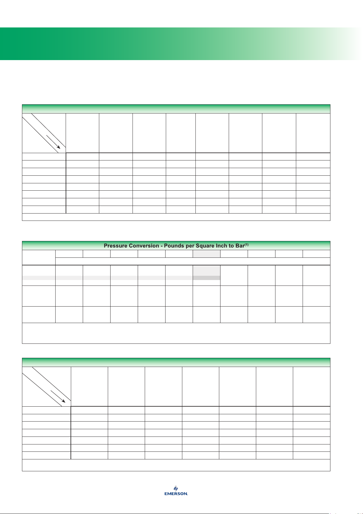
Pressure Conversion - Pounds per Square Inch to Bar
POUNDS PER
SQUARE INCH
0
10
20
30
40
50
60
70
80
90
100
1. To convert to kilopascals, move decimal point two positions to the right; to convert to megapascals, move decimal point one position to the left.
*Note: Round off decimal points to provide no more than the desired degree of accuracy.
To use this table, see the shaded example.
25 psig (20 from the left column plus ve from the top row) = 1,724 bar
0 1 2 3 4 5 6 7 8 9
Bar
0,000
0,689
1,379
2,068
2,758
3,447
4,137
4,826
5,516
6,205
6,895
0,069
0,758
1,448
2,137
2,827
3,516
4,275
4,964
5,585
6,274
6,964
0,138
0,827
1,517
2,206
2,896
3,585
4,275
4,964
5,654
6,343
7,033
0,207
0,896
1,586
2,275
2,965
3,654
4,344
5,033
5,723
6,412
7,102
0,276
0,965
1,655
2,344
3,034
3,723
4,413
5,102
5,792
6,481
7,171
0,345
1,034
1,724*
2,413
3,103
3,792
4,482
5,171
5,861
6,550
7,239
Volume Equivalents
TO
OBTAIN
CUBIC
BY
MULTIPLY
NUMBER
OF
Cubic Decimeters (Liters) 1 61.0234 0.03531 1.05668 0.264178 0,220083 0.00629
Cubic Inches 0,01639 1 5.787 x 10
Cubic Feet 28,317 1728 1 29.9221 7.48055 6,22888 0.1781
U.S. Quart 0,94636 57.75 0.03342 1 0.25 0,2082 0.00595
U.S. Gallon 3,78543 231 0.13368 4 1 0,833 0.02381
Imperial Gallon 4,54374 277.274 0.16054 4.80128 1.20032 1 0.02877
U.S. Barrel (Petroleum) 158,98 9702 5.6146 168 42 34,973 1
1 cubic meter = 1,000,000 cubic centimeters
1 liter = 1000 milliliters = 1000 cubic centimeters
DECIMETERS
(LITERS)
CUBIC INCHES CUBIC FEET U.S. QUART U.S. GALLON IMPERIAL GALLON
-4
1.01732 0.004329 0,003606 0.000103
U.S. BARREL
(PETROLEUM)
667
Te c h n i c a l
Conversions, Equivalents, and Physical Data
Volume Rate Equivalents
TO
OBTAIN
BY
MULTIPLY
NUMBER
OF
Liters per Minute 1 0,06 2.1189 60 0.264178 9.057
Cubic Meters per Hour 16,667 1 35.314 1000 4.403 151
Cubic Feet per Hour 0,4719 0,028317 1 28.317 0.1247 4.2746
Liters per Hour 0,016667 0,001 0.035314 1 0.004403 0.151
U.S. Gallons per Minute 3,785 0,2273 8.0208 227.3 1 34.28
U.S. Barrels per Day 0,1104 0,006624 0.23394 6.624 0.02917 1
LITERS
PER MINUTE
CUBIC METERS
PER HOUR
CUBIC FEET
PER HOUR
LITERS
PER HOUR
U.S. GALLONS
PER MINUTE
U.S. BARRELS
PER DAY
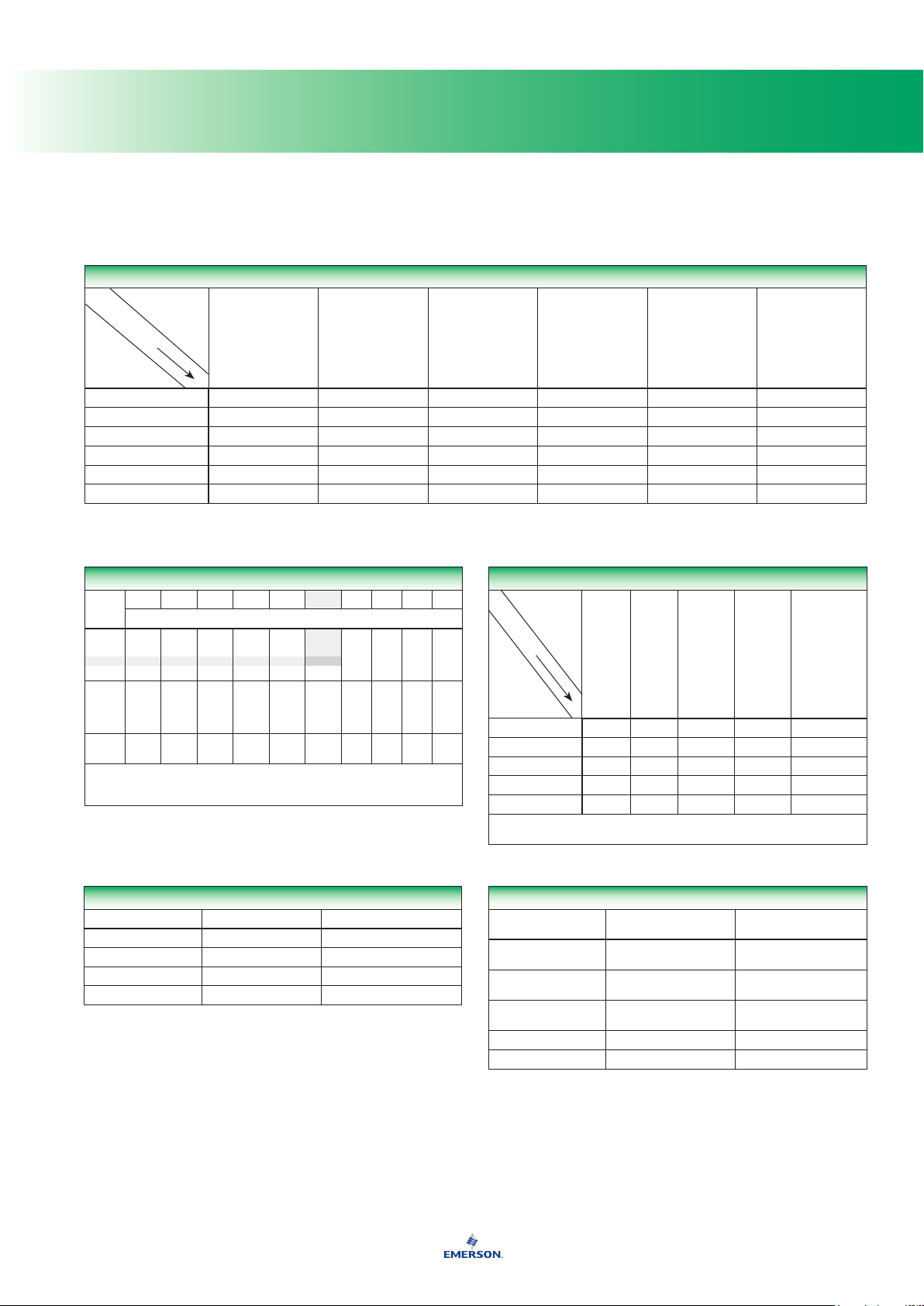
Mass Conversion - Pounds to Kilograms
POUNDS
1 pound = 0,4536 kilograms
*NOTE: To use this table, see the shaded example.
25 pounds (20 from the left column plus ve from the top row) = 11,34 kilograms
0 1 2 3 4 5 6 7 8 9
Kilograms
0
0,00
0,45
0,91
1,36
1,81
2,27
10
4,54
20
9,07
30
13,61
40
18,14
50
22,68
60
27,22
70
31,75
809036,29
40,82
4,99
9,53
14,06
18,60
23,13
27,67
32,21
36,74
41,28
5,44
9,98
14,52
19,05
23,59
28,12
32,66
37,20
41,73
5,90
10,43
14,97
19,50
24,04
28,58
33,11
37,65
42,18
6,35
10,89
15,42
19,96
24,49
29,03
33,57
38,10
42,64
6,80
11,34*
15,88
20,41
24,95
29,48
34,02
38,56
43,09
2,72
7,26
11,79
16,33
20,87
25,40
29,94
34,47
39,01
43,55
3,18
7,71
12,25
16,78
21,32
25,86
30,39
34,93
39,46
44,00
3,63
8,16
12,70
17,24
21,77
26,31
30,84
35,38
39,92
44,45
4,08
8,62
13,15
17,69
22,23
26,76
31,30
35,83
40,37
44,91
Temperature Conversion Formulas
TO CONVERT FROM TO SUBSTITUTE IN FORMULA
Degrees Celsius Degrees Fahrenheit (°C x 9/5) + 32
Degrees Celsius Kelvin (°C + 273.16)
Degrees Fahrenheit Degrees Celsius (°F - 32) x 5/9
Degrees Fahrenheit Degrees Rankine (°F + 459.69)
Area Equivalents
TO
OBTAIN
BY
MULTIPLY
NUMBER
OF
Square Meters 1 1549.99 10.7639 3.861 x 10
Square Inches 0,0006452 1 6.944 x 10-32.491 x 10
Square Feet 0,0929 144 1 3.587 x 10-89,29 x 10
Square Miles 2 589 999 - - - - 27,878,400 1 2,59
Square Kilometers 1 000 000 - - - - 10,763,867 0.3861 1
1 square meter = 10 000 square centimeters
1 square millimeter = 0,01 square centimeter = 0.00155 square inches
SQUARE
METERS
SQUARE
INCHES
SQUARE
FEET
SQUARE
MILES
SQUARE
KILOMETERS
-7
-10
6,452 x 10
1 x 10
Kinematic-Viscosity Conversion Formulas
VISCOSITY SCALE RANGE OF t, SEC
Saybolt Universal 32 < t < 100 t > 100
Saybolt Furol 25 < t < 40 t > 40
Redwood No. 1 34 < t < 100 t > 100
Redwood Admiralty - - - - 0.027t - 20/t
Engler - - - - 0.00147t - 3.74/t
KINEMATIC VISCOSITY,
STROKES
0.00226t - 1.95/t
0.00220t - 1.35/t
0.0224t - 1.84/t
0.0216t - 0.60/t
0.00226t - 1.79/t
0.00247t - 0.50/t
-6
-10
-8

668
Te c h n i c a l
Conversions, Equivalents, and Physical Data
Conversion Units
MULTIPLY BY TO OBTAIN
Volume
Cubic centimeter 0.06103 Cubic inches
Cubic feet 7.4805 Gallons (US)
Cubic feet 28.316 Liters
Cubic feet 1728 Cubic inches
Gallons (US) 0.1337 Cubic feet
Gallons (US) 3.785 Liters
Gallons (US) 231 Cubic inches
Liters 1.057 Quarts (US)
Liters 2.113 Pints (US)
Miscellaneous
BTU 0.252 Calories
Decitherm 10,000 BTU
Kilogram 2.205 Pounds
Kilowatt Hour 3412 BTU
Ounces 28.35 Grams
Pounds 0.4536 Kilograms
Pounds 453.5924 Grams
Pounds 21,591 LPG BTU
Therm 100,000 BTU
API Bbls 42 Gallons (US)
Gallons of Propane 26.9 KWH
HP 746 KWH
HP (Steam) 42,418 BTU
Pressure
Grams per square centimeter 0.0142 Pounds per square inch
Inches of mercury 0.4912 Pounds per square inch
Inches of mercury 1.133 Feet of water
Inches of water 0.0361 Pounds per square inch
Inches of water 0.0735 Inches of mercury
Inches of water 0.5781 Ounces per square inch
Inches of water 5.204 Pounds per foot
kPa 100 Bar
Kilograms per square centimeter 14.22 Pounds per square inch
Kilograms per square meter 0.2048 Pounds per square foot
Pounds per square inch 0.06804 Atmospheres
Pounds per square inch 0.07031 Kilograms per square centimeter
Pounds per square inch 0.145 KPa
Pounds per square inch 2.036 Inches of mercury
Pounds per square inch 2.307 Feet of water
Pounds per square inch 14.5 Bar
Pounds per square inch 27.67 Inches of water
Length
Centimeters 0.3937 Inches
Feet 0.3048 Meters
Feet 30.48 Centimeters
Feet 304.8 Millimeters
Inches 2.540 Centimeters
Inches 25.40 Millimeters
Kilometer 0.6214 Miles
Meters 1.094 Yards
Meters 3.281 Feet
Meters 39.37 Inches
Miles (nautical) 1853 Meters
Miles (statute) 1609 Meters
Yards 0.9144 Meters
Yards 91.44 Centimeters
Other Useful Conversions
TO CONVERT FROM TO MULTIPLY BY
Cubic feet of methane BTU 1000 (approximate)
Cubic feet of water Pounds of water 62.4
Degrees Radians 0,01745
Gallons Pounds of water 8.336
Grams Ounces 0.0352
Horsepower (mechanical) Foot pounds per minute 33,000
Horsepower (electrical) Watts 746
Kg Pounds 2.205
Kg per cubic meter Pounds per cubic feet 0.06243
Kilowatts Horsepower 1.341
Pounds Kg 0,4536
Pounds of Air
(14.7 psia and 60°F)
Pounds per cubic feet Kg per cubic meter 16,0184
Pounds per hour (gas) SCFH 13.1 ÷ Specic Gravity
Pounds per hour (water) Gallons per minute 0.002
Pounds per second (gas) SCFH 46,160 ÷ Specic Gravity
Radians Degrees 57.3
SCFH Air SCFH Propane 0.81
SCFH Air SCFH Butane 0.71
SCFH Air SCFH 0.6 Natural Gas 1.29
SCFH Cubic meters per hour 0.028317
Cubic feet of air 13.1
Converting Volumes of Gas
CFH TO CFH OR CFM TO CFM
Multiply Flow of By To Obtain Flow of
0.707 Butane
Air
Butane
Natural Gas
Propane
1.290 Natural Gas
0.808 Propane
1.414 Air
1.826 Natural Gas
1.140 Propane
0.775 Air
0.547 Butane
0.625 Propane
1.237 Air
0.874 Butane
1.598 Natural Gas
669
Te c h n i c a l
Conversions, Equivalents, and Physical Data
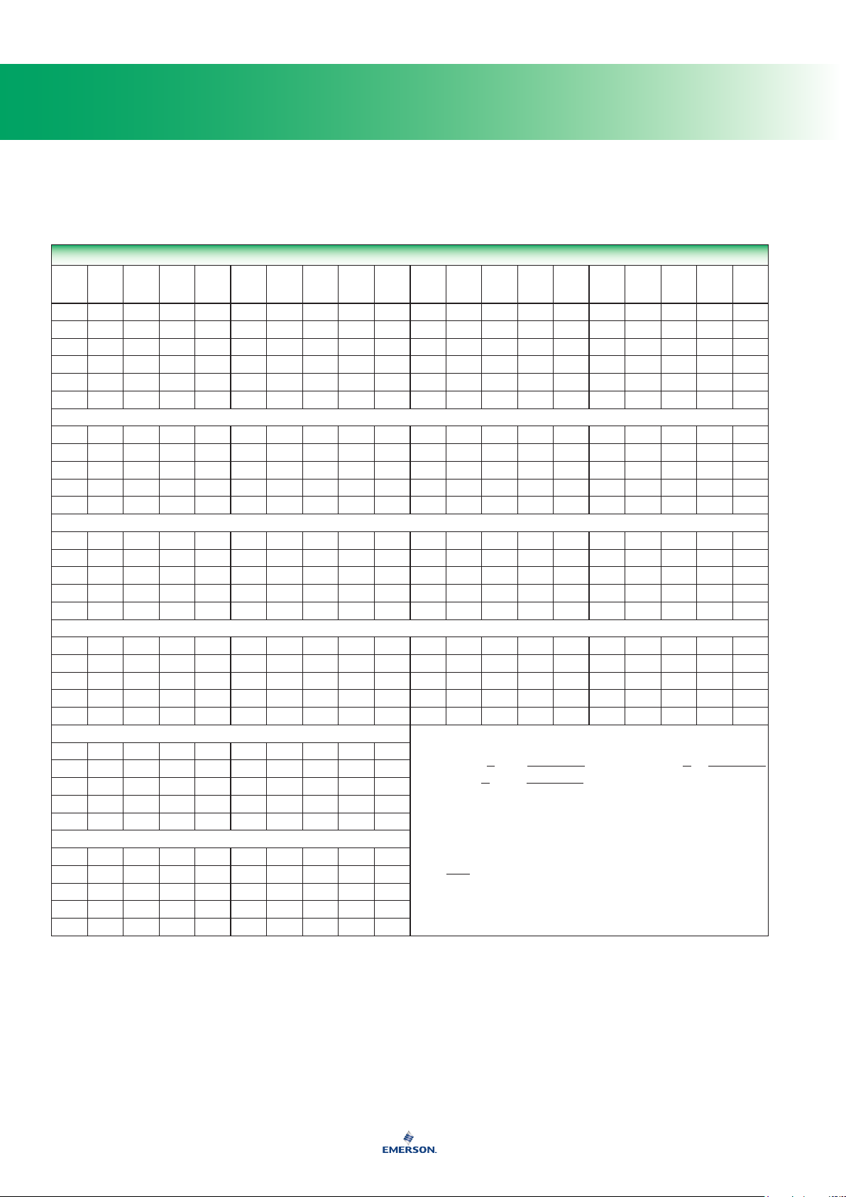
Fractional Inches to Millimeters
INCH
0
1
2
3
4
5
6
7
8
9
10
1-inch = 25,4 millimeters
NOTE: To use this table, see the shaded example.
2-1/2-inches (2 from the left column plus 1/2 from the top row) = 63,5 millimeters
MULTIPLY
NUMBER
OF
1 meter = 100 cm = 1000 mm = 0,001 km = 1,000,000 micrometers
0 1/16 1/8 3/16 1/4 5/16 3/8 7/16 1/2 9/16 5/8 11/16 3/4 13/16 7/8 15/16
0,0
25,4
50,8
76,2
101,6
127,0
152,4
177,8
203,2
228,6
254,0
1,6
27,0
52,4
77,8
103,2
128,6
154,0
179,4
204,8
230,2
255,6
3,2
28,6
54,0
79,4
104,8
130,2
155,6
181,0
206,4
231,8
257,2
4,8
30,2
55,6
81,0
106,4
131,8
157,2
182,6
208,0
233,4
258,8
6,4
31,8
57,2
82,6
108,0
133,4
158,8
184,2
209,6
235,0
260,4
7,9
33,3
58,7
84,1
109,5
134,9
160,3
185,7
211,1
236,5
261,9
9,5
34,9
60,3
85,7
111,1
136,5
161,9
187,3
212,7
238,1
263,5
11,1
36,5
61,9
87,3
112,7
138,1
163,5
188,9
214,3
239,7
265,1
mm
12,7
38,1
63,5
88,9
114,3
139,7
165,1
190,5
215,9
241,3
266,7
14,3
39,7
65,1
90,5
115,9
141,3
166,7
192,1
217,5
242,9
268,3
15,9
41,3
66,7
92,1
117,5
142,9
168,3
193,7
219,1
244,5
269,9
17,5
42,9
68,3
93,7
119,1
144,5
169,9
195,3
220,7
246,1
271,5
19,1
44,5
69,9
95,3
120,7
146,1
171,5
196,9
222,3
247,7
273,1
20,6
46,0
71,4
96,8
122,2
147,6
173,0
198,4
223,8
249,2
274,6
Length Equivalents
TO
OBTAIN
BY
Meters 1 39.37 3.2808 1000 0.0006214 0,001
Inches 0,0254 1 0.0833 25,4 0.00001578 0,0000254
Feet 0,3048 12 1 304,8 0.0001894 0,0003048
Millimeters 0,001 0.03937 0.0032808 1 0.0000006214 0,000001
Miles 1609,35 63,360 5,280 1 609 350 1 1,60935
Kilometers 1000 39,370 3280.83 1 000 000 0.62137 1
METERS INCHES FEET MILLIMETERS MILES KILOMETERS
22,2
47,6
73,0
98,4
123,8
149,2
174,6
200,0
225,4
250,8
276,2
23,8
49,2
74,6
100,0
125,4
150,8
176,2
201,6
227,0
252,4
277,8
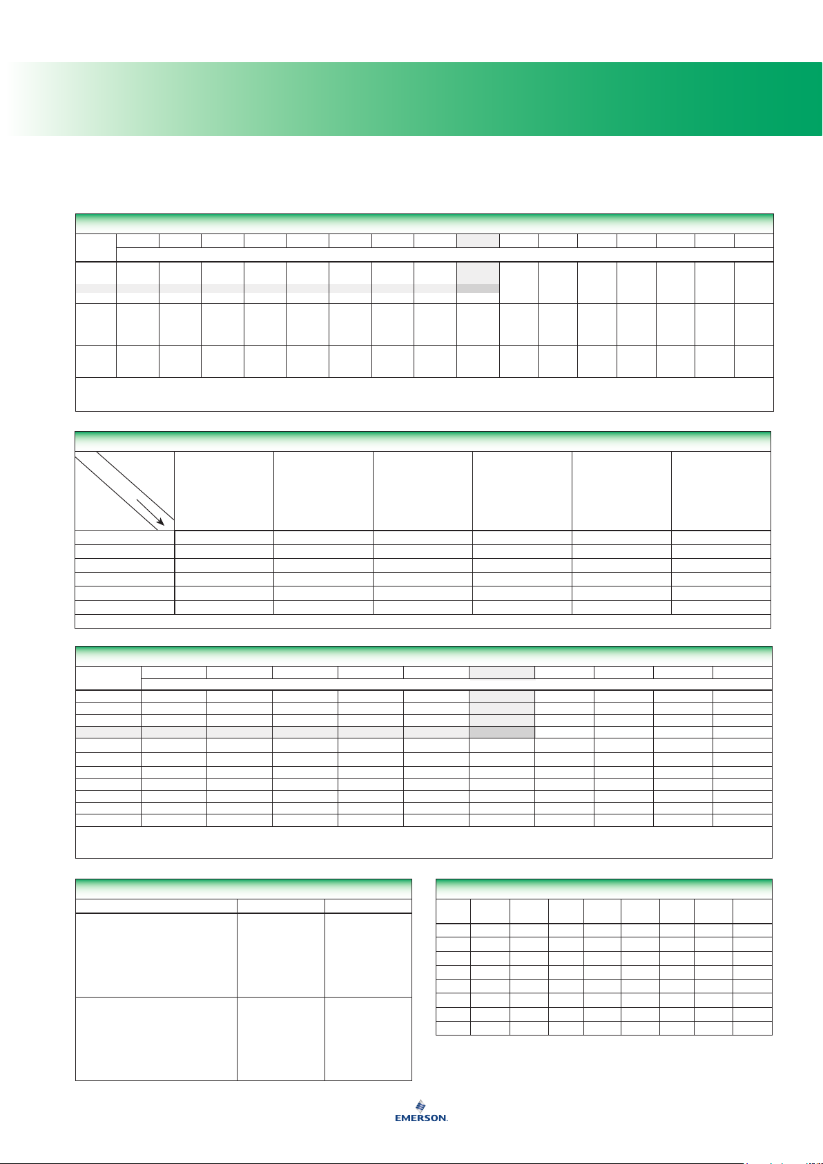
Whole Inch-Millimeter Equivalents
INCH
0 0,00 25,4 50,8 76,2 101,6 127,0 152,4 177,8 203,2 228,6
10 254,0 279,4 304,8 330,2 355,6 381,0 406,4 431,8 457,2 482,6
20 508,0 533,4 558,8 584,2 609,6 635,0 660,4 685,8 711,2 736,6
30 762,0 787,4 812,8 838,2 863,6 889,0 914,4 939,8 965,2 990,6
40 1016,0 1041,4 1066,8 1092,2 1117,6 1143,0 1168,4 1193,8 1219,2 1244,6
50 1270,0 1295,4 1320,8 1346,2 1371,6 1397,0 1422,4 1447,8 1473,2 1498,6
60 1524,0 1549,4 1574,8 1600,2 1625,6 1651,0 1676,4 1701,8 1727,2 1752,6
70 1778,0 1803,4 1828,8 1854,2 1879,6 1905,0 1930,4 1955,8 1981,2 2006,6
80 2032,0 2057,4 2082,8 2108,2 2133,6 2159,0 2184,4 2209,8 2235,2 2260,6
90 2286,0 2311,4 2336,8 2362,2 2387,6 2413,0 2438,4 2463,8 2489,2 2514,6
100 2540,0 2565,4 2590,8 2616,2 2641,6 2667,0 2692,4 2717,8 2743,2 2768,6
Note: All values in this table are exact, based on the relation 1-inch = 25,4 mm.
To use this table, see the shaded example.
25-inches (20 from the left column plus ve from the top row) = 635 millimeters
MULTIPLICATION FACTOR PREFIX SYMBOL
1 000 000 000 000 000 000 = 10
1 000 000 000 000 000 = 10
0.000 000 000 000 001 = 10
0.000 000 000 000 000 001 = 10
0 1 2 3 4 5 6 7 8 9
Metric Prexes and Symbols
1 000 000 000 000 = 10
1 000 000 000 = 10
1 000 000 = 10
1 000 = 10
100 = 10
10 = 10
0.1 = 10
0.01 = 10
0.001 = 10
0.000 01 = 10
0.000 000 001 = 10
0.000 000 000 001 = 10
18
15
12
9
6
3
2
1
-1
-2
-3
-6
-9
-12
-15
-18
exa
peta
tera
giga
mega
kilo
hecto
deka
deci
centi
milli
micro
nano
pico
femto
atto
E
P
T
G
M
k
h
da
d
c
m
m
n
p
f
a
mm
Greek Alphabet
LOWER
CASE
GREEK
NAME
CAPS
Α α Alpha Ι ι Iota Ρ ρ Rho
Β β Beta Κ κ Kappa Σ σ Sigma
Γ γ Gamma Λ λ Lambda Τ τ Tau
Δ δ Delta Μ μ Mu Υ υ Upsilon
Ε ε Epsilon Ν ν Nu Φ φ Phi
Ζ ζ Zeta Ξ ξ Xi Χ χ Chi
Η η Eta Ο ο Omicron Ψ ψ Psi
Θ θ Theta Π π Pi Ω ω Omega
CAPS
LOWER
CASE
GREEK
NAME
CAPS
LOWER
CASE
GREEK
NAME

670
Te c h n i c a l
Conversions, Equivalents, and Physical Data
Length Equivalents - Fractional and Decimal Inches to Millimeters
INCHES
Fractions Decimals Fractions Decimals Fractions Decimals Fractions Decimals
0.00394 0.1 0.23 5.842 1/2 0.50 12.7 0.77 19.558
0.00787 0.2 15/64 0.234375 5.9531 0.51 12.954 0.78 19.812
0.01 0.254 0.23622 6.0 0.51181 13.0 25/32 0.78125 19.8438
0.01181 0.3 0.24 6.096 33/64 0.515625 13.0969 0.78740 20.0
1/64 0.015625 0.3969 1/4 0.25 6.35 0.52 13.208 0.79 20.066
0.01575 0.4 0.26 6.604 0.53 13.462 51/64 0.796875 20.2406
0.01969 0.5 17/64 0.265625 6.7469 17/32 0.53125 13.4938 0.80 20.320
0.02 0.508 0.27 6.858 0.54 13.716 0.81 20.574
0.02362 0.6 0.27559 7.0 35/64 0.546875 13.8906 13/64 0.8125 20.6375
0.02756 0.7 0.28 7.112 0.55 13.970 0.82 20.828
0.03 0.762 9/32 0.28125 7.1438 0.55118 14.0 0.82677 21.0
1/32 0.03125 0.7938 0.29 7.366 0.56 14.224 53/64 0.828125 21.0344
0.0315 0.8 19/64 0.296875 7.5406 9/16 0.5625 14.2875 0.83 21.082
0.13543 0.9 0.30 7.62 0.57 14.478 0.84 21.336
0.03937 1.0 0.31 7.874 37/64 0.578125 14.6844 27/32 0.84375 21.4312
0.04 1.016 5/16 0.3125 7.9375 0.58 14.732 0.85 21.590
3/64 0.046875 1.1906 0.31496 8.0 0.59 14.986 55/64 0.859375 21.8281
0.05 1.27 0.32 8.128 0.5905 15.0 0.86 21.844
0.06 1.524 21/64 0.328125 8.3344 19/32 0.59375 15.0812 0.86614 22.0
1/16 0.0625 1.5875 0.33 8.382 0.60 15.24 0.87 22.098
0.07 1.778 0.34 8.636 39/64 0.609375 15.4781 7/8 0.875 22.225
5/64 0.078125 1.9844 11/32 0.34375 8.7312 0.61 15.494 0.88 22.352
0.07874 2.0 0.35 8.89 0.62 15.748 0.89 22.606
0.08 2.032 0.35433 9.0 5/8 0.625 15.875 57/64 0.890625 22.6219
0.09 2.286 23/64 0.359375 9.1281 0.62992 16.0 0.90 22.860
3/32 0.09375 2.3812 0.36 9.144 0.63 16.002 0.90551 23.0
0.1 2.54 0.37 9.398 0.64 16.256 29/32 0.90625 23.0188
7/64 0.109375 2.7781 3/8 0.375 9.525 41/64 0.640625 16.2719 0.91 23.114
0.11 2.794 0.38 9.652 0.65 16.510 0.92 23.368
0.11811 3.0 0.39 9.906 21/32 0.65625 16.6688 59/64 0.921875 23.1456
0.12 3.048 25/64 0.390625 9.9219 0.66 16.764 0.93 23.622
1/8 0.125 3.175 0.39370 10.0 0.66929 17.0 15/16 0.9375 23.8125
0.13 3.302 0.40 10.16 0.67 17.018 0.94 23.876
0.14 3.556 13/32 0.40625 10.3188 43/64 0.671875 17.0656 0.94488 24.0
9/64 0.140625 3.5719 0.41 10.414 0.68 17.272 0.95 24.130
0.15 3.810 0.42 10.668 11/16 0.6875 17.4625 61/64 0.953125 24.2094
5/32 0.15625 3.9688 27/64 0.421875 10.7156 0.69 17.526 0.96 24.384
0.15748 4.0 0.43 10.922 0.70 17.78 31/32 0.96875 24.6062
0.16 4.064 0.43307 11.0 45/64 0.703125 17.8594 0.97 24.638
0.17 4.318 7/16 0.4375 11.1125 0.70866 18.0 0.98 24.892
11/64 0.171875 4.3656 0.44 11.176 0.71 18.034 0.98425 25.0
0.18 4.572 0.45 11.430 23/32 0.71875 18.2562 63/64 0.984375 25.0031
3/16 0.1875 4.7625 29/64 0.453125 11.5094 0.72 18.288 0.99 25.146
0.19 4.826 0.46 11.684 0.73 18.542 1 1.00000 25.4000
0.19685 5.0 15/32 0.46875 11.9062 47/64 0.734375 18.6531
0.2 5.08 0.47 11.938 0.74 18.796
13/64 0.203125 5.1594 0.47244 12.0 0.74803 19.0
0.21 5.334 0.48 12.192 3/4 0.75 19.050
7/32 0.21875 5.5562 31/64 0.484375 12.3031 0.76 19.304
0.22 5.588 0.49 12.446 49/64 0.765625 19.4469
Note: Round off decimal points to provide no more than the desired degree of accuracy.
mm
INCHES
mm
INCHES
mm
INCHES
mm

671
Te c h n i c a l
Conversions, Equivalents, and Physical Data
Temperature Conversions
TEMP. IN °C
°C
OR °F TO BE
CONVERTED
-273,16 -460 -796 -90,00 -130 -202.0 -17,8 0 32.0 21,1 70 158.0
-267,78 -450 -778 -84,44 -120 -184.0 -16,7 2 35.6 22,2 72 161.6
-262,22 -440 -760 -78,89 -110 -166.0 -15,6 4 39.2 23,3 74 165.2
-256,67 -430 -742 -73,33 -100 -148.0 -14,4 6 42.8 24,4 76 168.8
-251,11 -420 -724 -70,56 -95 -139.0 -13,3 8 46.4 25,6 78 172.4
-245,56 -410 -706 -67,78 -90 -130.0 -12,2 10 50.0 26,7 80 176.0
-240,00 -400 -688 -65,00 -85 -121.0 -11,1 12 53.6 27,8 82 179.6
-234,44 -390 -670 -62,22 -80 -112.0 -10,0 14 57.2 28,9 84 183.2
-228,89 -380 -652 -59,45 -75 -103.0 -8,89 16 60.8 30,0 86 186.8
-223,33 -370 -634 -56,67 -70 -94.0 -7,78 18 64.4 31,1 88 190.4
-217,78 -360 -616 -53,89 -65 -85 -6,67 20 68.0 32,2 90 194.0
-212,22 -350 -598 -51,11 -60 -76.0 -5,56 22 71.6 33,3 92 197.6
-206,67 -340 -580 -48,34 -55 -67.0 -4,44 24 75.2 34,4 94 201.2
-201,11 -330 -562 -45,56 -50 -58.0 -3,33 26 78.8 35,6 96 204.8
-195,56 -320 -544 -42,78 -45 -49.0 -2,22 28 82.4 36,7 98 208.4
°F °C
TEMP. IN °C
OR °F TO BE
CONVERTED
°F °C
TEMP. IN °C
OR °F TO BE
CONVERTED
°F °C
TEMP. IN °C
OR °F TO BE
CONVERTED
°F
-190,00 -310 -526 -40,00 -40 -40.0 -1,11 30 86.0 37,8 100 212.0
-184,44 -300 -508 -38,89 -38 -36.4 0 32 89.6 43,3 110 230.0
-178,89 -290 -490 -37,78 -36 -32.8 1,11 34 93.2 48,9 120 248.0
-173,33 -280 -472 -36,67 -34 -29.2 2,22 36 96.8 54,4 130 266.0
-169,53 -273 -459.4 -35,56 -32 -25.6 3,33 38 100.4 60,0 140 284.0
-168,89 -272 -457.6 -34,44 -30 -22.0 4,44 40 104.0 65,6 150 302.0
-167,78 -270 -454.0 -33,33 -28 -18.4 5,56 42 107.6 71,1 160 320.0
-162,22 -260 -436.0 -32,22 -26 -14.8 6,67 44 111.2 76,7 170 338.0
-156,67 -250 -418.0 -31,11 -24 -11.2 7,78 46 114.8 82,2 180 356.0
-151,11 -240 -400.0 -30,00 -22 -7.6 8,89 48 118.4 87,8 190 374.0
-145,56 -230 -382.0 -28,89 -20 -4.0 10,0 50 122.0 93,3 200 392.0
-140,00 -220 -364.0 -27,78 -18 -0.4 11,1 52 125.6 98,9 210 410.0
-134,44 -210 -356.0 -26,67 -16 3.2 12,2 54 129.2 104,4 220 428.0
-128,89 -200 -328.0 -25,56 -14 6.8 13,3 56 132.8 110,0 230 446.0
-123,33 -190 -310.0 -24,44 -12 10.4 14,4 58 136.4 115,6 240 464.0
-117,78 -180 -292.0 -23,33 -10 14.0 15,6 60 140.0 121,1 250 482.0
-112,22 -170 -274.0 -22,22 -8 17.6 16,7 62 143.6 126,7 260 500.0
-106,67 -160 -256.0 -21,11 -6 21.2 17,8 64 147.2 132,2 270 518.0
-101,11 -150 -238.0 -20,00 -4 24.8 18,9 66 150.8 137,8 280 536.0
-95,56 -140 -220.0 -18,89 -2 28.4 20,0 68 154.4 143,3 290 665.0
-continued-

672
Te c h n i c a l
Conversions, Equivalents, and Physical Data
Temperature Conversions (continued)
°C
21,1 70 158.0 204,4 400 752.0 454,0 850 1562.0
22,2 72 161.6 210,0 410 770.0 460,0 860 1580.0
23,3 74 165.2 215,6 420 788.0 465,6 870 1598.0
24,4 76 168.8 221,1 430 806.0 471,1 880 1616.0
25,6 78 172.4 226,7 440 824.0 476,7 890 1634.0
26,7 80 176.0 232,2 450 842.0 482,2 900 1652.0
27,8 82 179.6 237,8 460 860.0 487,8 910 1670.0
28,9 84 183.2 243,3 470 878.0 493,3 920 1688.0
30,0 86 186.8 248,9 480 896.0 498,9 930 1706.0
31,1 88 190.4 254,4 490 914.0 504,4 940 1724.0
32,2 90 194.0 260,0 500 932.0 510,0 950 1742.0
33,3 92 197.6 265,6 510 950.0 515,6 960 1760.0
34,4 94 201.2 271,1 520 968.0 521,1 970 1778.0
35,6 96 204.8 276,7 530 986.0 526,7 980 1796.0
36,7 98 208.4 282,2 540 1004.0 532,2 990 1814.0
TEMP. IN °C
OR °F TO BE
CONVERTED
°F °C
TEMP. IN °C
OR °F TO BE
CONVERTED
°F °C
TEMP. IN °C
OR °F TO BE
CONVERTED
°F
37,8 100 212.0 287,8 550 1022.0 537,8 1000 1832.0
43,3 110 230.0 293,3 560 1040.0 543,3 1010 1850.0
48,9 120 248.0 298,9 570 1058.0 548,9 1020 1868.0
54,4 130 266.0 304,4 580 1076.0 554,4 1030 1886.0
60,0 140 284.0 310,0 590 1094.0 560,0 1040 1904.0
65,6 150 302.0 315,6 600 1112.0 565,6 1050 1922.0
71,1 160 320.0 321,1 610 1130.0 571,1 1060 1940.0
76,7 170 338.0 326,7 620 1148.0 576,7 1070 1958.0
82,2 180 356.0 332,2 630 1166.0 582,2 1080 1976.0
87,8 190 374.0 337,8 640 1184.0 587,8 1090 1994.0
93,3 200 392.0 343,3 650 1202.0 593,3 1100 2012.0
98,9 210 410.0 348,9 660 1220.0 598,9 1110 2030.0
104,4 220 428.0 354,4 670 1238.0 604,4 1120 2048.0
110,0 230 446.0 360,0 680 1256.0 610,0 1130 2066.0
115,6 240 464.0 365,6 690 1274.0 615,6 1140 2084.0
121,1 250 482.0 371,1 700 1292.0 621,1 1150 2102.0
126,7 260 500.0 376,7 710 1310.0 626,7 1160 2120.0
132,2 270 518.0 382,2 720 1328.0 632,2 1170 2138.0
137,8 280 536.0 287,8 730 1346.0 637,8 1180 2156.0
143,3 290 665.0 393,3 740 1364.0 643,3 1190 2174.0
-continued-

673
Te c h n i c a l
Conversions, Equivalents, and Physical Data
Temperature Conversions (continued)
TEMP. IN °C
°C
OR °F TO BE
CONVERTED
148,9 300 572.0 315,6 600 1112.0 482,2 900 1652.0 648,9 1200 2192.0
154,4 310 590.0 321,1 610 1130.0 487,8 910 1670.0 654,4 1210 2210.0
160,0 320 608.0 326,7 620 1148.0 493,3 920 1688.0 660,0 1220 2228.0
165,6 330 626.0 332,2 630 1166.0 498,9 930 1706.0 665,6 1230 2246.0
171,1 340 644.0 337,8 640 1184.0 504,4 940 1724.0 671,1 1240 2264.0
176,7 350 662.0 343,3 650 1202.0 510,0 950 1742.0 676,7 1250 2282.0
182,2 360 680.0 348,9 660 1220.0 515,6 960 1760.0 682,2 1260 2300.0
187,8 370 698.0 354,4 670 1238.0 521,1 970 1778.0 687,8 1270 2318.0
189,9 380 716.0 360,0 680 1256.0 526,7 980 1796.0 693,3 1280 2336.0
193,3 390 734.0 365,6 690 1274.0 532,2 990 1814.0 698,9 1290 2354.0
204,4 400 752.0 371,1 700 1292.0 537,8 1000 1832.0 704,4 1300 2372.0
210,0 410 770.0 376,7 710 1310.0 543,3 1010 1850.0 710,0 1310 2390.0
215,6 420 788.0 382,2 720 1328.0 548,9 1020 1868.0 715,6 1320 2408.0
221,1 430 806.0 287,8 730 1346.0 554,4 1030 1886.0 721,1 1330 2426.0
226,7 440 824.0 393,3 740 1364.0 560,0 1040 1904.0 726,7 1340 2444.0
°F °C
TEMP. IN °C
OR °F TO BE
CONVERTED
°F °C
TEMP. IN °C
OR °F TO BE
CONVERTED
°F °C
TEMP. IN °C
OR °F TO BE
CONVERTED
°F
232,2 450 842.0 398,9 750 1382.0 565,6 1050 1922.0 732,2 1350 2462.0
237,8 460 860.0 404,4 760 1400.0 571,1 1060 1940.0 737,8 1360 2480.0
243,3 470 878.0 410,0 770 1418.0 576,7 1070 1958.0 743,3 1370 2498.0
248,9 480 896.0 415,6 780 1436.0 582,2 1080 1976.0 748,9 1380 2516.0
254,4 490 914.0 421,1 790 1454.0 587,8 1090 1994.0 754,4 1390 2534.0
260,0 500 932.0 426,7 800 1472.0 593,3 1100 2012.0 760,0 1400 2552.0
265,6 510 950.0 432,2 810 1490.0 598,9 1110 2030.0 765,6 1410 2570.0
271,1 520 968.0 437,8 820 1508.0 604,4 1120 2048.0 771,1 1420 2588.0
276,7 530 986.0 443,3 830 1526.0 610,0 1130 2066.0 776,7 1430 2606.0
282,2 540 1004.0 448,9 840 1544.0 615,6 1140 2084.0 782,2 1440 2624.0
287,8 550 1022.0 454,4 850 1562.0 621,1 1150 2102.0 787,0 1450 2642.0
293,3 560 1040.0 460,0 860 1580.0 626,7 1160 2120.0 793,3 1460 2660.0
298,9 570 1058.0 465,6 870 1598.0 632,2 1170 2138.0 798,9 1470 2678.0
304,4 580 1076.0 471,1 880 1616.0 637,8 1180 2156.0 804,4 1480 2696.0
310,0 590 1094.0 476,7 890 1634.0 643,3 1190 2174.0 810,0 1490 2714.0
674
Te c h n i c a l
Conversions, Equivalents, and Physical Data
A.P.I. and Baumé Gravity Tables and Weight Factors
A.P.I.
Baumé
Specic
Gravity
Gravity
0 10.247 1.0760 8.962 0.1116 - - - - - - - - - - - - - - - - - - - - - - - - - - - - - - - - - - - - - - - - - - - - - - - - - - - - - - - - - - - -
1 9.223 1.0679 8.895 0.1124 31 30.78 0.9808 7.251 0.1379 61 60.46 0.7351 6.119 0.1634 81 80.25 0.6659 5.542 0.1804
2 8.198 1.0599 8.828 0.1133 32 31.77 0.8654 7.206 0.1388 62 61.45 0.7313 6.087 0.1643 82 81.24 0.6628 5.516 0.1813
3 7.173 1.0520 8.762 0.1141 33 32.76 0.8602 7.163 0.1396 63 62.44 0.7275 6.056 0.1651 83 82.23 0.6597 5.491 0.1821
4 6.148 1.0443 8.698 0.1150 34 33.75 0.8550 7.119 0.1405 64 63.43 0.7238 6.025 0.1660 84 83.22 0.6566 5.465 0.1830
5 5.124 1.0366 8.634 0.1158 35 34.73 0.8498 7.075 0.1413 65 64.42 0.7201 6.994 0.1668 85 84.20 0.6536 5.440 0.1838
6 4.099 1.0291 8.571 0.1167 36 35.72 0.8448 7.034 0.1422 66 65.41 0.7165 5.964 0.1677 86 85.19 0.6506 5.415 0.1847
7 3.074 1.0217 8.509 0.1175 37 36.71 0.8398 6.993 0.1430 67 66.40 0.7128 5.934 0.1685 87 86.18 0.6476 5.390 0.1855
8 2.049 1.0143 8.448 0.1184 38 37.70 0.8348 6.951 0.1439 68 67.39 0.7093 5.904 0.1694 88 87.17 0.6446 5.365 0.1864
9 1.025 1.0071 8.388 0.1192 39 38.69 0.8299 6.910 0.1447 69 68.37 0.7057 5.874 0.1702 89 88.16 0.6417 5.341 0.1872
10 10.00 1.0000 8.328 0.1201 40 39.68 0.8251 6.870 0.1456 70 69.36 0.7022 5.845 0.1711 90 89.15 0.6388 5.316 0.1881
Gravity
Lbs/U.S.
Gallons
U.S.
Gallons-
/Lb
A.P.I.
Gravity
Baumé
Gravity
Specic
Gravity
Lbs/U.S.
Gallons
U.S.
Gallons-
/Lb
A.P.I.
Gravity
Baumé
Gravity
Specic
Gravity
Lbs/U.S.
Gallons
U.S.
Gallons-
/Lb
A.P.I.
Gravity
Baumé
Gravity
Specic
Gravity
Lbs/U.S.
Gallons
U.S.
Gallons-
/Lb
11 10.99 0.9930 8.270 0.1209 41 40.67 0.8203 6.830 0.1464 71 70.35 0.6988 5.817 0.1719 91 90.14 0.6360 5.293 0.1889
12 11.98 0.9861 8.212 0.1218 42 41.66 0.8155 6.790 0.1473 72 71.34 0.6953 5.788 0.1728 92 91.13 0.6331 5.269 0.1898
13 12.97 0.9792 8.155 0.1226 43 42.65 0.8109 6.752 0.1481 73 72.33 0.6919 5.759 0.1736 93 92.12 0.6303 5.246 0.1906
14 13.96 0.9725 8.099 0.1235 44 43.64 0.8063 6.713 0.1490 74 73.32 0.6886 5.731 0.1745 94 93.11 0.6275 5.222 0.1915
15 14.95 0.9659 8.044 0.1243 45 44.63 0.8017 6.675 0.1498 75 74.31 0.6852 5.703 0.1753 95 94.10 0.6247 5.199 0.1924
16 15.94 0.9593 7.989 0.1252 46 45.62 0.7972 6.637 0.1507 76 75.30 0.6819 5.676 0.1762 96 95.09 0.6220 5.176 0.1932
17 16.93 0.9529 7.935 0.1260 47 50.61 0.7927 6.600 0.1515 77 76.29 0.6787 5.649 0.1770 97 96.08 0.6193 5.154 0.1940
18 17.92 0.9465 7.882 0.1269 48 50.60 0.7883 6.563 0.1524 78 77.28 0.6754 5.622 0.1779 98 97.07 0.6166 5.131 0.1949
19 18.90 0.9402 7.930 0.1277 49 50.59 0.7839 6.526 0.1532 79 78.27 0.6722 5.595 0.1787 99 98.06 0.6139 5.109 0.1957
20 19.89 0.9340 7.778 0.1286 50 50.58 0.7796 6.490 0.1541 80 79.26 0.6690 5.568 0.1796 100 99.05 0.6112 5.086 0.1966
The relation of degrees Baume or A.P.I. to Specic Gravity is expressed by these formulas:
21 20.88 0.9279 7.727 0.1294 51 50.57 0.7753 6.455 0.1549
22 21.87 0.9218 7.676 0.1303 52 51.55 0.7711 6.420 0.1558
23 22.86 0.9159 7.627 0.1311 53 52.54 0.7669 6.385 0.1566
24 23.85 0.9100 7.578 0.1320 54 53.53 0.7628 6.350 0.1575
25 24.84 0.9042 7.529 0.1328 55 54.52 0.7587 6.136 0.1583
26 25.83 0.8984 7.481 0.1337 56 55.51 0.7547 6.283 0.1592
27 26.82 0.8927 7.434 0.1345 57 56.50 0.7507 6.249 0.1600
28 27.81 0.8871 7.387 0.1354 58 57.49 0.7467 6.216 0.1609
29 28.80 0.8816 7.341 0.1362 59 58.48 0.7428 6.184 0.1617
30 29.79 0.8762 7.296 0.1371 60 59.47 0.7389 6.151 0.1626
For liquids lighter than water: For liquids heavier than water:
Degrees Baume = Degrees Baume =
Degrees A.P.I. =
G = Specic Gravity = ratio of weight of a given volume of oil at 60°F to the weight of the same
volume of water at 60°F.
The above tables are based on the weight of 1 gallon (U.S.) of oil with a volume of 231 cubic
inches at 60°F in air at 760 mm pressure and 50% relative humidity. Assumed weight of 1 gallon
of water at 60°F in air is 8.32828 pounds.
To determine the resulting gravity by mixing oils of different gravities:
D =
D = Density or Specic Gravity of mixture
m = Proportion of oil of d1 density
n = Proportion of oil of d2 density
d1 = Specic gravity of m oil
d2 = Specic gravity of n oil
140 140
- 130 G =
G 130 + Degrees Baume
141 141.5
- 131.5 G =
5 131.5 + Degrees A.P.I.
md1+md
2
m + n
145 145
145 - G =
5 145 – Degrees Baume

675
Te c h n i c a l
Conversions, Equivalents, and Physical Data
Characteristics of the Elements
ELEMENT SYMBOL
Actinium
Aluminum
Americum
Antimony
(Stibium)
Argon
Arsenic
Astatine
Barium
Berkelium
Beryllium
Bismuth
Boron
Bromine
Cadmium
Calcium
Californium
Carbon
Cerium
Cesium
Chlorine
Chromium
Cobalt
Copper
Curium
Dysprosium
Einsteinium
Erbium
Europium
Fermium
Fluourine
Francium
Gadolinium
Gallium
Germanium
Gold
Hafnium
Helium
Holmium
Hydrogen
Indium
Iodine
Iridium
Iron
Krypton
Lanthanum
Lawrencium
Lead
Lithium
Lutetium
Magnesium
Manganese
Mendelevium
Mercury
Molybdenum
Neodymium
1. Mass number shown is that of stable isotope most common in nature. Mass numbers shown in parentheses designate the isotope with the longest half-life (slowest rate of
radioactive decay) for those elements having an unstable isotope.
2. Calculated
> Greater than
Ac
Am
Sb
Ar
As
Ba
Bk
Be
Br
Cd
Ca
Cf
Ce
Cs
Cr
Co
Cu
Cm
Dy
Es
Er
Eu
Fm
Gd
Ga
Ge
Au
Hf
He
Ho
Fe
Kr
La
Lw
Pb
Lu
Mg
Mn
Mv
Hg
Mo
Nd
Al
At
Bi
B
C
Cl
F
Fr
H
In
I
Ir
Li
ATOMIC
NUMBER
89
13
95
51
18
33
85
56
97
4
83
5
35
48
20
98
6
58
55
17
24
27
29
96
66
99
68
63
100
9
87
64
31
32
79
72
2
67
1
49
53
77
26
36
57
103
82
3
71
12
25
101
80
42
60
MASS
NUMBER
(227)
27
(243)
121
40
75
(210)
138
(247)
9
209
11
79
114
40
(249)
12
140
133
35
52
59
63
(248)
164
(254)
166
153
(252)
19
(223)
158
69
74
197
180
4
165
1
115
127
193
56
84
139
(257)
208
7
175
24
55
(256)
202
98
142
MELTING
(1)
POINT (°C)
sublimes at 615
1278±5
1150±50
-259.14
2620±10
BOILING
POINT (°C)
1600†
659.7
630.5
-189.2
sublimes at 615
850
271.3
2300
-7.2
320.9
842±8
>3550
804
28.5
-103±5
1890
1495
1083
-223 -188
29.78
958.5
1063
1700
-272
156.4
113.7
2454
1535
-156.6
826
327.43
186
651
1260
-38.87
840
1560±5
(2)
2000±10
184.35
1336±5
356.58
2057
1380
-185.7
1140
2970
2550
58.78
767±2
1240
4200
1400
670
-34.6
2480
2900
2336
1983
2700
2600
>3200
-268.9
-252.8
>4800
3000
-152.9
1620
1107
1900
4800
ELEMENT SYMBOL
Neon
Neptunium
Nickel
Niobium
Nitrogen
Nobelium
Osmium
Oxygen
Palladium
Phosphorus
Platinum
Plutonium
Polonium
Potassium
Praseodymium
Promethium
Protactinium
Radium
Radon
Rhenium
Rhodium
Rubidium
Ruthenium
Samarium
Scandium
Selenium
Silicon
Silver
Sodium
Strontium
Sulfur
Tantalum
Technetium
Tellurium
Terbium
Thallium
Thorium
Thulium
Tin
Titanium
Tungsten
(Wolfram)
Uranium
Vanadium
Xenon
Ytterbium
Yttrium
Zinc
Zirconium
Ne
Np
Nb
No
Os
Pd
Pu
Po
Pm
Pa
Ra
Rn
Re
Rh
Rb
Ru
Sm
Sc
Se
Ag
Na
Ta
Tc
Te
Tb
Th
Tm
Sn
Xe
Yb
Zn
ATOMIC
NUMBER
10
102
93
28
41
7
76
8
46
15
78
94
84
19
59
61
91
88
86
75
45
37
44
62
21
34
14
47
11
38
16
73
43
52
65
81
90
69
50
22
74
92
23
54
70
39
30
40
Ni
N
O
P
Pt
K
Pr
Si
Sr
S
Tl
Ti
W
U
V
Y
Zr
MASS
NUMBER
20
(237)
58
93
14
(253)
192
16
106
31
195
(242)
(209)
39
141
(145)
(231)
(226)
(222)
187
103
85
102
152
45
80
28
107
23
88
32
180
(99)
130
159
205
232
169
120
48
184
238
51
132
174
89
64
90
(1)
MELTING
POINT (°C)
-248.67
1455
2500±50
-209.86
2700
-218.4
1549.4
1773.5
53.3
940
700
-71
3167±60
1966±3
38.5
2450
>1300
1200
217
1420
960.8
97.5
800
2996±50
452
327±5
302
1845
231.89
1800
3370
c.1133
1710
-112
1800
1490
419.47
1857
BOILING
POINT (°C)
-245.9
2900
3700
-195.8
>5300
-182.86
2000
4300
760
1140
-61.8
>2500
700
2700
2400
688
2355
1950
880
1150
c.4100
1390
1457±10
4500
2270
>3000
5900
3000
-107.1
2500
907
>2900
 Loading...