

Page 1

Page 2

International
ii
Office:
Fisher &
PO
Auckland
New
Telephone:
Facsimile:
Part
Revision F December
Technical
Fisher & Paykel
without
Australian
Fisher & Paykel
36-40
Victoria
Australia
Telephone
Facsimile
Paykel
Box
14348
Zealand.
Number
Manual
notice
New
3134
Healthcare
Panmure,
+64-9-574
+64-9-574
185
Office:
St
Ringwood.
0100
0158
040 735
1998
for
HC100
Healthcare
Healthcare
+61-3-9879
+61-3-9879
Pty
Respiratory
have a policy
Ltd.
5022
5232
Humidifier.
of
continued
product
improvement
UK
and
Ireland:
Fisher &
Unit
Clivemont
Maidenhead,
United
Telephone
Facsimile
Paykel
16,
Cordwallis
Kingdom
and
(EU
Authorised
Healthcare
Park
Road
SL6
7BU
+44-1628-626-136
+44-1628-626-146
reserve
Ltd.
the
right
to
alter
т
Representative)
specifications
USA
Office:
Fisher &
22982
Suite
Laguna
USA
Telephone
Facsimile
Changes
Anodise
Paykel
Alcalde
101
Hills,
Remove
Remove
Healthcare
Drive
Ca
92653
+1-714-470-3900
+1-714-470-3933
to
technical
ion
of
change
standoffs
A
from
late
ix B Maintance
Inc.
manual
heaterplate
since
Schedule
last
version
France/Benelux:
Fisher & Paykel
10
Avenue
SILIC
91946
France
Telephone
Facsimile
du
S12-Villebon
Courtaboeuf-Cedex
Healthcare
Quebec
_+33-164-46-52-01
+33-164-46-52-21
SAS.
HC100
.
Technical
Manual
“
Revision F Issued
December
1998
Page 3
iii
1.0
11
12
13
2.0
2.1
2.2
3.0
3.1
32
4.0
4.1
42
GENERALINFORMATION
Application...
HC100
Standards
CIRCUIT
Temperature
Overheat
PERFORMANCE
Performance
СаНбтаНоп
SERVICING
Printed
Heaterplate..….....................
Electrical
and
Protection...
Specifications...
Approvals
OPERATION
Control
CHECK....vsscererizionieeezzresizre
Check
Procedure
..........
Circuit
ле
иоииизиииииолиинииининониозпипиикилиииинивииниши
INEORMATION
Board
μμ
...
Removal
μα,
eee
i...
Table
eee
eee
μμ
μμ
of
Contents
nee
REA
iii
erener
HR RR
RAKA
PRK
eee
reiezione
page
sanan
À
1
1
2
2
1.0
1.1
1.2 | HC100
GENERAL
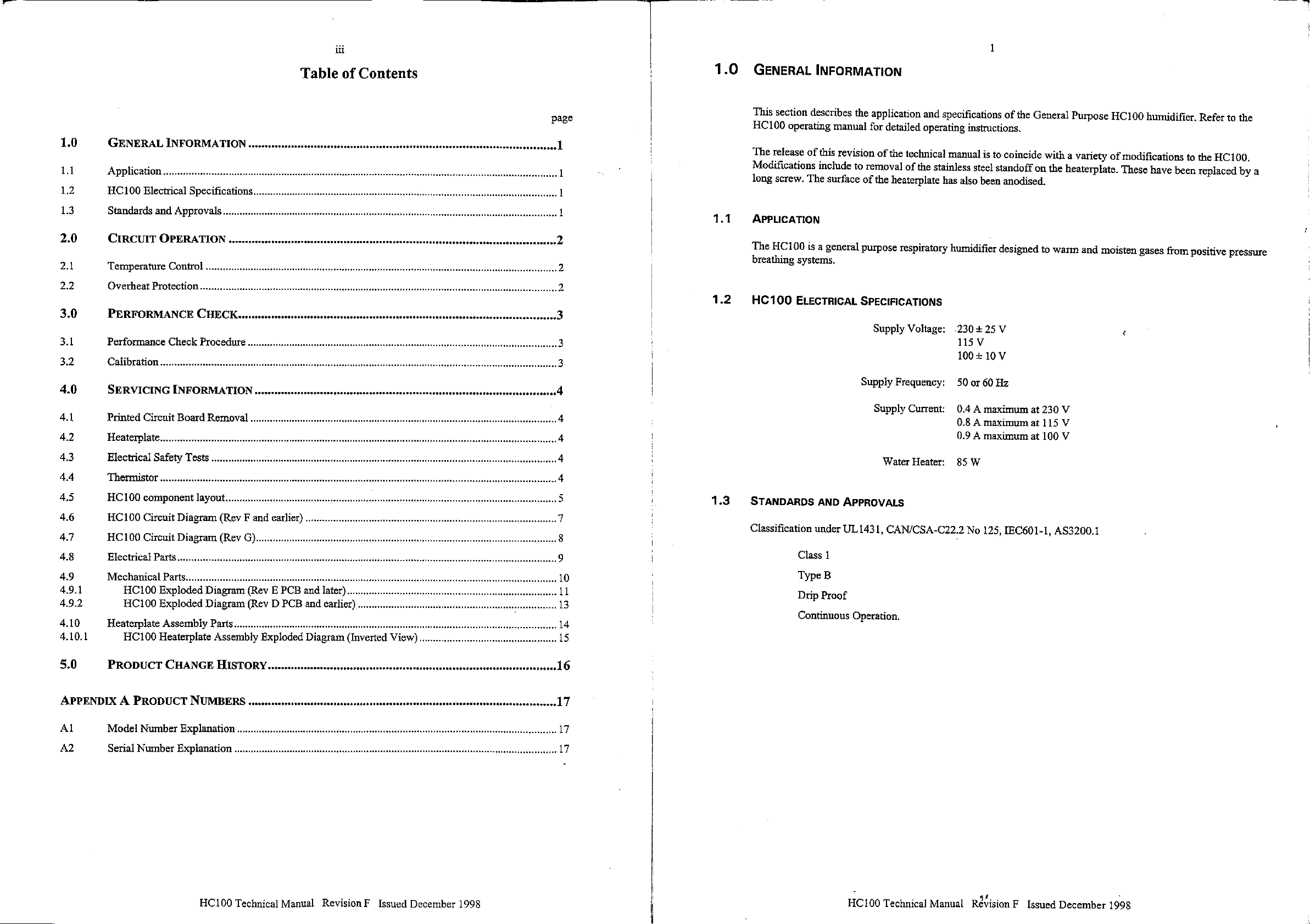
This
HC100
The
Modifications
long
APPLICATION
The
breathing
venseriensvenzerinienenioninionezeonenenceosacenientonsenseenioenÌ
iii
eee
нити
интиилиининтивнишониинциниильннизьвтиотитиивтививльвлитшинчия
irene
Re
ee
iene
einen
3
3
4
4
section
operating
release
screw.
HC100
systems.
ELECTRICAL
INFORMATION
describes
of
this
include
The
is
a
the
manual
revision
to
surface
general
SPECIFICATIONS
removal
of
purpose
Supply
application
for
detailed
of
the
the
Supply
Supply
and
operating
technical
of
the
heaterplate
respiratory
Voltage:
Frequency:
Current:
specifications
instructions.
manual
stainless
has
is
to
steel
standoff
also
been
humidifier
.230+25
115
100
50
0.4 A maximum
0.8 A maximum
0.9 A maximum
V
+
or
10
60
V
Hz
of
the
General
coincide
on
anodised.
designed
V
at
at
at
Purpose
with
a
variety
the
heaterplate.
to
warm
230
V
115
V
100
V
and
HC100
of
moisten
humidifier.
modifications
These
gases
г
have
from
to
the
been
replaced
positive
Refer
HC100.
to
the
by
a
pressure
,
43
4.4
45
4.6
4.7
4,8
4.9
4.9.1
4.9.2
4.10
4.10.1
5.0
APPENDIX A PRODUCT
A1
A2
Electrical
Thermistor
HC100
HC100
HC100
Electrical
Mechanical
Heaterplate
PRODUCT
Model
Serial
component
Circuit
Circuit
HC100
HC100
HC100
Number
Number
Safety
.........cesssssssssssscsssssenssnsecssevenceronsssnseenececssensensssonenscsesonsesonsvecsecuessesaesuasssosissecsueassassssseneaanessanesee
Parts...
Parts
Exploded
Exploded
Assembly
Heaterplate
........нньллиилинниольнитиионииолициинити
layout...
Diagram
Diagram
Diagram
Diagram
Parts...
CHANGE
NUMBERS
Explanation
линии
тининнитииолонитинипонивуиилнииинивтиилинонивтлииитивтиванечии
Re
(Rev F and
(Rev
res
rr
Assembly
HISTORY...
AN
inner
earlier)
GC)...
errare
rrrereererenreresererrercasearareacrsicre
(Rev E PCB
(Rev D PCB
Exploded
rene
inner
and
later)
and
earlier)
Diagram
sacra
asas
...
cerros
(Inverted
eee
iara
na
cas
none
View)
e.
carente
rear teen e ease
ee
recrerreca
ninar
eentasaas
4
4
5
7
8
9
ll
.13
17
17
1.3
STANDARDS
Classification
under
Class
Type
Drip
Continuous
AND
1
B
Proof
Water
APPROVALS
UL
1431,
CAN/CSA-C22.2
Operation.
Heater:
85
W
No
125,
IEC601-1,
AS3200.1
HC100
Technical
Manual
RevisionF
Issued
December
1998
HC100
Technical
Manual
Révision
F
Issued
December
1998
Page 4

2.0
2.1
2.2
CIRCUIT
TEMPERATURE
(Component
Operating
serves
The
precision
resistor
R10
by
switching
provides a fast
switching
voltage
OVERHEAT
An
overheat
failure
OPERATION
references
power
aS 2 power-on
temperature
network
Uld,
connected
level
on
and
as
the
gate
PROTECTION
protector
that
may
CONTROL
are
for the
indicator.
of
RS, R7,
as a voltage
for
the
comparator
switching
off.
Lastly,
current
(93 + 5
cause
uncontrolled
to
the
circuit
electronic
sensing
R4,
output
to
circuits
thermistor
R6
and
to
the
U1b
acts
Q1
is
°C)
is
and
switched
heating,
diagrams
is
provided
(TH),
VR]
completes
comparator.
the
remaining
gate
of
triac
as a shunt
on
and
mounted
on
the
in
§4.6
and
by
the
in
series
the
The
output
active
Q1
to
control
voltage
the
protector
regulator
off.
heaterplate
will
§4.7)
network
with
R8,
bridge
of
VR1
circuit
the
assembly.
open
R15,
R16,
D3,
forms
one
arm
circuit.
The
bridge
buffered
components.
heaterplate.
to
maintain a relatively
and
by
the
Ule,
LED2
If
there
is
disconnect
all
follower
and
C1, A green
of a wheatstone
output
is
monitored
stage,
Ulc,
another
an
power
comparator
indicates
electronic
heaterplate
constant
to
the
component
circuit
heater
LED
(LED1)
bridge.
The
through
sets
stage,
operating
base.
the
3.0
3.1
PERFORMANCE
The
performance
used
to
check
the
When
stability
base
and
heaterplate
on
and
off
remains
PERFORMANCE
1
Fill
an
HC300
2
Place a 300
3
4
5
6
7
resting
Turn
Allow
Read
The
on
the
60
the
temperature
Check
that
heater
thermometer.
CHECK
check
should
operation
has
been
obtained,
from
the
within + 1
CHECK
mm
the
minutes
‘power’
PROCEDURE
humidification
alcohol-in-glass
chamber
control
for
should
and
be
of
the
ideal
°C.
bottom.
knob
the
water
It
should
continue
‘heat
done
after the
HCi00
the
heater base
actual
flat
condition.
chamber
thermometer
fully
clockwise
temperature
be
within
to
cycle
on’
lights
HC100
water
temperature
The
to
the
correct
and
to
the
within
are
operating.
has
been
without
variation
vertically
stabilise.
range
the
dismantling
will
level
through
turn
on
the
of 50
calibration
serviced
depend
of
the
water
with
water
the
power.
to
66
°C.
range
due
to a fault.
the
unit.
slightly
and
outlet
of
on
temperature
slide
port
‘
50
to
66
the
it
onto
of
°C
the
This
procedure
deviation
as
the
heaterplate
the
heaterplate.
chamber
of
the
with
is
to
be
chamber
switches
the
bulb
3.2
CALIBRATION
The
HC100
not
require
The
precise
humidifier
any
calibration.
temperature
is
controlled
and
stability
by a precision
of
the
humidifier
thermistor
can
be
and
close
checked
tolerance
during
the
electronic
performance
components
check
and
does
procedure.
HC100
Technical
Manual
Revision F Issued
December
1998
HC100
Technical
Manual
Révision F Issued
December
1998
Page 5

4.0
4.1
4.2
SERVICING
This
section
humidifier
circuit.
PRINTED
1
2
3
4 — Ifthe
important:
On
220
HEATERPLATE
case
Note
CIRCUIT
The
HC100
The
case
from
the
Remove
two
the
circuit
reassembly
to
240 V models
INFORMATION
provides
that
the
information
the
performance
no
calibration
BOARD
case
top
assembly
circuit
board.
AC
power
plastic
board
can
with a new
is
retaining
REMOVAL
opened
can
line
be
popped
for
servicing
check
procedure
is
required.
by
removing
now
be
cable
from
latches
up
PCB,
be
the
the 3 fixing
moved
(just
aside
the
terminal
in
front
allowing
sure
to
HC100
in
§3
and
of
the
board
check
humidifier
should
be
screws
the
two
block
on
the
earth
to
be
that
After
carried
from
under
wiring
the
circuit
studs)
are
withdrawn
link
LK1
any
out
to
the
harness
board,
moved
away
has
been
servicing
confirm
humidifier
cable
backwards
from
involving
the
connectors
the
cut
{or
opening
operation
body.
disconnected
slightly,
front
panel.
removed)
of
the
the
of
control
rear
for
the
the
of
4.5
HC100
Revision D and
RIO
00
(Destas
FISHER & PAYKEL
ELECTRONICS
HEALTHCARE
(©
347 040
Ra
RU
COMPONENT
earlier
LAYOUT
(Revision C shown)
e
2
O
LULAS
nesse
οἱ
Ten
e
HOR
06 02 03
er
a
E
ee
ea
1993
LTD.
DIV.
HCÍDO
339
REV
C
347
LK2
7
1
CUT
LINK
ts
Mer
040
8———e
FOR
610
16
339
p
NO
고
230VAC 7 ot
Y
reve
yp
HIGH
пи
i
Y
я
CAUTION
VOLTAGE
A
-
LE02
=
ン
シン
ン
p,
и
Y
4.3
4.4
The
reset
button
the
front
panel
screws
that
secure
slotting
A
Then
ELECTRICAL
After
in
THERMISTOR
them
tip
to
aid the
place
the
the
HC100
accordance
Test
Earth
Resistance
Insulation
Earth
Leakage Measure
for
the
case
assembly.
it
to
into
the
recesses
replacement
spring
over
SAFETY
has
been
with
the
Resistance
93
°C
over
The
the
front
for
of
the
them.
TESTS
serviced
relevant
country
temperature
heaterplate
case.
On
replacing
them
on
the
heaterplate
Then
use
the
the
following
regulations.
Method
Use
on
the
Check
worn.
Use a 500
the
phase
210MQ
heaterplate . Earth
operating
0.5
protector
can
be
detached
the
heaterplate.
is
to
place
drill
blanks
electrical
an
ohmmeter
mains
plug
humidifier
VDC
pin on
earth
leakage
voltage
mA
maximum.
is
accessible
from
the
heaterplate,
@2.2
to
safety
and
to
power
insulation
the
mains
leakage
and
ensure
mm
drill
guide
the
tests
measure
the
heaterplate.
cable
tester
plug
with
the
current
frequency
through a small
front
case
assembly
that
the
three
blanks
in
each
heaterplate
should
the
resistance
for
damage
to
measure
to
the
earth
is
of
power
and
be
performed
from
It
should
be < 0.2
and
the
heaterplate.
probe
of
measured
supply.
hole
under
by
springs
of
the
standoff
the
upper
or
the
earth
Q.
replace
the
at
if
resistance
It
should
tester
normal
It
should
the
heaterplate
removing
are
case
electrical
cut
from
on
the
in
place
screw
together.
safety
pin
or
be
the
be
in
three
by
holes.
tests
、
Revision
FISHER & PAYKEL
ELECTRONICS
HEALTHCARE
©
347
E
9
1995
HC⑩0
040 339
LTD.
DIV,
REVE
010547
O
A
kL
040
Lal
359
REV
me?
ce
FOR
238VAC
xi
06
CUT
LINK
ais
eu
re
Nan
RN
Ale
ジン
00-
а
ee
ン
ン
ン
The
type
used
the
the
095428291
of
thermistor
095428156
thermistor
used
on
the
thermistor
HC100
in
with a 680R
Technical
HC100
conjunction
varies
with a 560R
resistor
in
Manual
depending
location
Revision F Issued
on
the
resistor
R6.
age
in
of
the
unit.
location
December
R6.
1998
Older
The
later
Rev F and
Rev G PCB
earlier
units
units
use
HC100
Technical
Manual
ReVisionF
Issued
December
1998
Page 6

Revision
bele
E
=
οἱ
ο
G
L
zer)
ny
+
',
i
小
5
8
x
|,
19
mino:
©
s
8228
85S
ale
НЯ
n
ul
©
io
3
¿2582
ser
=
=
te
el
==>:
0
PME
らら
мыс
5
м
0x5.
cer
16
e
9
o
>
E
\
„
je
=
N
mo
No
ENNN
e
=
@
è
o
Ne
、
be
|
5
=
。
-
τς
2
X
©
es
o
m
wm
οἱ
|
Μ
@
3
o
o
e
H
3
ら
O
==
\
®
o
을
월식
LOR]
EN
NA
a
X
=
N
22
>
5
®
=
+1
|
N
à
sl
&
4.6
Ss
AIN
”
+
MALA
NY
x
HC100
2
I
9
L
5
E
[
CIRCUIT
D
ASH
003
307
DIAGRAM
a
D
ag
Е
aye
|
一
ag
品
a
EXE
一
一
NO
1037
83000
(REV F AND
El
m
o
om
30
o
xl
98
8095
EARLIER)
ain
X,
NazenÌ
ン
js
TBA
3,17
dao
차
ni
3022
.
Y)
wo
|
ΝΥΖΕΝΊ
xe
aura
x=
4078
a
100+—+0—v18
000S-95H9
Σο
REF]
+
1
13345
30
ἩΒΒΜΩΝ
886
070
9NIAVHO
Sr0
Eta
fg
ALUMNO
μμ
LV
140218
OJAO8IEY
0
38
mt
ISO
ουν
SINIS
기보
16060
mW
3
=
JTVDE
LOM
00
1665
ϐ)
03』23!0Md
kaAdo2
"UM
OE 73310
时 30
po
|
=
J
017
JAMAVd
NOISIAIO
SONOYLIITI
IUVIHLIWIH
TANAVd
®
43Н$]|
好
33HSH
cromo
|
cono
|
замы
sima
wm
ня
+
Ts
“3ΒΠΛΗΝό
“ANANYA
‘ONVWWaZ
rio
16178)
ΒΥΣ-Υὶ
“OU
MAN
4
000-606
INIBUVO
‘ONY
XOB
(619)
DIONY
"Od
SZ
10
45643
」
NO
2031
HaLV3H
MENT
10m
su
оо
る
ta
し
41434056
ЗАЛАХ
HC100
Technical
Manual
Revision F Issued
December
1998
]
1
7
H
on
G
8
=
E
3
Эн} 9
O
Sl
35YHd
2277
vAS
i
1
;
1
1
i
330/N0
L
a
ο)
È
|
È
.
을
a
=
É
2
5
8
3
!
я
!
440/80
3
n
A
<a
5
w
|
=
2
E
8
о
te
ALNAN
|
8
δι
Hisy3
ЕВЕ
이
El
회
El
BL
El
В
El
Bj
E
E)
El
ELİ
EF
ВЕ
FFP
FT
FT
PE
FT
altel
Stel
EI.
Sela
SFERE
È
SR
È
計ら
이리
に
9
EEE
Тин
MEME
mimimjolo(mj>
Юз
EEE
HE
AINDA
AGNA
SI
NOIVANO
ΒΗΗΗ
DE
sE]
SINE
E
E
Page 7

4.7
HC100
CIRCUIT
DIAGRAM
NE No
58
(REV
G)
É
3
elx
Eis
gx
=
e 5
Е
同
8 き
き
=
a
Es
3
zâ
“>
e
5
8
må
23
3
=
2
BØN
SE%
Ez)
<a
PADYERSY
A47
58
ee
n
nS
8
> =
2
= = -
σα
녹이
e
2
SE]
<
5
Е
a 때
=
5
Ba
3
ша
è
a
м +
<
a
El
=
*
BS
ME
Et
o
5
>
3 s n
&
a
y
5
Е
ne
5%
JC
TIVI
ЗЕЕ
=
ЕЯ
23
zg
A
=
e
eS
65
e
8
8
s
1a
284
o
1
8
É
E
to
as
Tx
25
ze
n
es
aga
ds
3,
|
レル
=4-----
i
1
'
t
i
!
1
i
E
1
<
1
E
oa
위
1
a s
s
Y
기
y
コー
ニー
ニー
ニー
キーーー コ ーー
4
zg
9.9
>
e
a a
g
a
n
ニー
У
ニー ニー
ニー
4-94
ーー
コーーーー
Wa
ュ
1
1
го
LOB
È
i
!
1
ГЕ
i
i
eh
5
2
e
<
£
---\
5
$
È
3
同
s
а
4d
3
y
vi
고
8
E
зы
В
=
&
&
a
<
=
-
lã
불
a
da
LU
Zu
ое
と
らき
<>
Es
asess:
O
O85 8 28/5
cido
шос
Bae
ЗЕЕ
Ores
W
3
еб
DUS
πω
U
Zda
â
CHECKED
SURELES
Rama
S.
К
BRT
[98756759
CETTE
區
707y0
[πε
220]
| の 76e]
7871071:
2110
git
ge
oN
Zang
ss
ὃν ὁ S|
PTIT
ETT
999
966 | мания
KES)
Trie
EZANI
Fe]
FETE
RENTE
SI
2834
2z
OM
ЗОНЕ
a
ча
esse
EEC
EE
z
otr
STE
(md
Sys
savona
mou
Taken
HODNOU]
NOR
ав
|
i
i
шы
|
n°
3
аа
Ξ
оз
53
ее
STARTS
PRODUCTION
UUAWITIY
BEFORE
SCHEMATIC
APPROVED
BE
WUST
HC100
SCRPTION
‘SAUPLUS
АВК
ОТ
м
E
=
SCALE
ROT
‘DO
ВЯ
CD
PROTECTED
COPYRKHT
Ht.
LTO
PAYKEL
&
FISHER
OF
PROPERTY
EXCLUSIVE
THE
[5
&
9
À
SM
13
НИТ
CONFOENTOL
Bİ
MCHLY
TS
|
4
BEORMATON
<lmlolaju
à
TS
TAS
4.8
ELECTRICAL
electrical
The
(refer
§4.5)
and
LEDI,LED2
R10,R11,Ri2,Ri3
SW1Switch
PARTS
components
HC100
R15,
Ref.
F1,F2
J2
J2
J3
J4
Qt
U1
RI,R3
R2
R4
RS
R6
Re
R7,R8
R9
#14
RI6
DPDT
SWI
TH
TH
VRi
85
93°C
Circuit
W
been
have
below
listed
Diagram
Part
043040686
043040988
999830001
341040403
341040532
999800059
999800039
361040329
999550009
999600002
325040299
325040309 _ Resistor
325040632
325040352
325040135
325040459
325040136
325040281 | Resisťor
325040284
325040280
3295040041
349040102
349040129
095428156
095428291
327041564
043040898
043040897
043040896
3490400514
.
999840001
No.
(refer
§4.6
Description
HC100
HC100
Fuse
Lock
Lock
Lock
Terminal
LED
Triac4
O
Quad
IC
Resistor
Resistor
Resistor
Resistor
Resistor
Resistor
Resistor
Resistor
Resistor
Switch
Switch
Thermistor
Thermistor
5k
Potentiometer
Element
|
Element
Element
Thermostat
Clip
referenced
&
§4.7).
PCB
Assembly
PCB
Assembly
(20
* 5
mm) I A.
Header
Header
Wafer
green
Block
5
A
Op
1Kk5
180R
270R
8k2
560R
680R
820R
1k
10k
680R
3k9 5 W
Toggle
Rocker
assembly
assembly
assembly
holder
5-way
5-way
3-way
2-way
mA
Amp
0.25 W 5%
0.25 W 5%
0.25
0.25 W 1%
0.25
0.25
0.25
0.25 W 5%
0.25
0.25
(Rev
(Rev
and
and
manual
5mm
according
(rev D and
(rev E and
(Rev E &
(Rev G &
&
E
(Rev
Trigger
LM324
1%
W
0.5%
W
0.5%
W
0.5%
W
5%
W
5%
W
earlier)
&
D
later
&
E
harness
harness
assembly.
assembly.
V
100
115
V
230
V
reset
diameter
HC100
the
to
earlier)
later).
earlier)
later)
earlier)
Film
Metal
Film
Metal
Film
Metal
PCB)
(Rev
(Rev
Component
*
&
F
(Rev
G)
(Rev
earlier)
4
F
G)
Layout
earlier)
diagram
HC100
Technical
Manual
Revision F Issued
December
1998
HC100
Technical
Manual
Révision
Issued
F
December
1998
Page 8

4.9
MECHANICAL
Reference
Unless
to
otherwise
Ref.
1
2
3
4
5
6
7
8
9
10
10
11
11
12
13
14
15
16
17
18
19
20
PARTS
the
HC100
043040939
043040940
043040941
662040040
662040058
043040829
043040855
043040709
043040851
614040116
336060143
614040117
614040120
622040130
641040723
043040686
043040988
281151303
serial
336060128
095428189
095428193
095428218
095428225
095428245
exploded
stated,
the
Part
No.
349040130
Specify
693040554
693040634
693040517
095428190
095428246
095428247
095428251
693040476
693040477
614040220
full
number
Specifyfull
serial
number
336060126
diagram
reference
Description
Heaterplate
Heaterplate
Heaterplate
Spring
Spring
Chamber
Chamber
Guard
Guard
Screw
Standoff
Screw
Screw
Washer
Plate
PCB
PCB
Boot
Boot
Case
O-Ring
Knob
Knob
Foot
Mains
Mains
Mains
Mains
Mains
Mains
Mains
Mains
Mains
mm2
Clamp
Clamp
Screw
Case
Gasket
in
§4.8.1
numbers
Earth
Assembly
Assembty
Switch
Switch
Lower
Control
Control
HC100
Upper
are
Assembly
Assembly
Assembly
Mounting
Heaterplate
Clamp
Clamp
Chamber
Chamber
M3
x 5
Pan
Heaterpiate
M4 x 8
#8 x 1/2
Cord
Cord
Cord
Cord
Cord
Cord
Cord
Cord
Cord
Cord
Cord
#6 x 3/8
Pan
Lock
M4
HC100
Toggle
Rocker
HC100
HC100
HC100
HC100
2.0 m HC100
2.0 m HC100
2.4 m 3C
2.0 m Schuko
2.4 m USA
2.4m
2.4 m 3C
2.0 m Schuko
2.0 m 3C
Small
Large
HC100
Clamp
MR700/HC100
10
and
§4.8.2.
valid
for
85 W 100
85 W 115
85 W 230
(Standoff
non-standoff
HC100
Kit
Kit
Pan
HC100
HC100
13
Pozi
Charcoal
Charcoal
Phil
Taptite
post
Phil
Taptite
Phil
TY25
(Rev
(Rev E «
AT-428
(Rev E &
mm
ID
Grey
Charcoal
USA
Hospital
USA
Hospital
USA
UK
TY25
fit
both
diagrams.
V
V
V
Heaterplate)
Kit
(Standoff
(Non-Standoff
S/S
D &
earlier
later
(Rev D &
later
7.5 A 240 V Grey
Clr
Plug
Domestic
Plug
3C
Grade
Grade
Domestic
Plug
3C Black
(BS1363)
Zn/St
Heaterplate)
PCB)
PCB)
earlier
PCB)
7.5 A NZ/Aust
Plug
White
Plug
Plug
Plug
Fused
Heaterplate)
PCB)
(no
plug)
Grey
Grey
Black
Black
White
1.0
i
4.9.1
HC100
|
ExpLopen
Diacram
(REv
E
PCB
AND
и
LATER)
© ©
900600
HC100
Technical
Manual
Revision F Issued
December
1998
HC100
Technical
Manual
Revision F Issued
December
1998
Page 9

12
.
4.9.2
HC100
ExPLOoDED
DIAGRAM
(Rev
D
pce
AND
B
EARLIER)
HC100
Technical
Manual
Revision
Issued
F
December
1998
:
HC100
Technical
Manual
RevisionF
Issued
December
1998
Page 10

14
15
4.10
HEATERPLATE
Reference
to
Ref.
PUN-
nu
10
11
12
ASSEMBLY
the
heaterplate
Part
331040154
614040117
641040707
043040898
043040897
043040896
614040116
331040114
095428156
095428291
043040942
095428303
622040130
349040051
095428279
exploded
No,
PARTS
Description
Insulator
Screw
Cover
Element
Element
Element
Screw
Insulator
Thermistor
Thermistor
Heaterplate
Harness
Washer
Thermostat
Hamess
diagram
in
§4.9.1.
Heaterplate
M4 8 Pan
Element
M3 x 5
Lock
Plate
Assembly
Assembly
Assembly
Taptite
Element
and
Harness
and
Hamess
Heaterplate - Earth
M4
93
°C
J7 - Heaterplate
Phil
Taptite
100 V
115 V 85
230 V 85
Pan
Assembly
Assembly
Int
Zn/PI
85
W
W
W
Phil
YChr
(Rev F and
(Rev
G)
earlier)
4.10.1
HC100
HEATERPLATE
ASSEMBLY
ExPLODED
DIAGRAM
(INVERTED
VIEW)
©
©
© ©
OY
OMO
HC100
Technical
Manual
Revision F Issued
December
1998
HC100
Technical
Manual
Révision
F
Issued
December
1998
Page 11

16
17
5.0
PRODUCT
This
circuit
Date
11
MAY
1
MAY
9-DEC-1996
21-MAY
2-SEP-1998
change
history
diagrams,
1995
1996
1997
CHANGE
§4.6
Change
Number
HISTORY
details
changes
&
$4.7.
2413
2598
3041
3301
3816
which
(The
serial
First
serial
affected
9510XXX13451
9610XXX06459
9610XXX20412
9710XXX28456
9810XXX32690
may
have
number
number
significance
format
is
explained
|
Comments
|
Introduce
|
Introduce
rocker
type.
|
Introduce
thermistor.
680
O.
Alter
|
Revised
|
Use
machined
in
production.
for
servicing.
in
appendix
rev
D
PCB.
rev.
E
PCB.
Change
Rev
Change
J3
heaterplate
PCB
G
PCB.
value
to
a
solder
with
anodised
Refer
also
A).
Change
Change
mains
to
Phenolic
to
of
R6
from
connection.
no
standoffs
heaterplate,
to
change
switch
2
kQ.
at
560
655040111
to
25°C
Q
to
panel
on
APPENDIX
This
serial
the
A1
MoDEL
e.g.
The
First
À
PRODUCT
section
number
product
NUMBER
for
HCLOOAHU:
HC100
Model
first
and
Letter
A
J
G
explains
number.
Type
second
how
individually
EXPLANATION
letters
Voltage
230420
115
V
100 + 10
NUMBERS
the
part
identifies
A
(first
Voltage
represent
Second
V
V
number
is
the
manufactured
letter)
the
following:
Letter
deciphered.
The
item.
H
(second
Language
Front Panel
English
French
German
model
The
model
letter)
number
number
refers
to
and
serial
U
(third
Customer
Side
Panels
ish/German
English/French
ish/French
English/German
a
specific
number
letter)
Specific
Language
variant
while
collectively
the
form
A2
SERIAL
e.g.
for
Year
96
The
three-letter
NUMBER
9610AHU03789:
EXPLANATION
Model
code
(e.g.
Number
AHU)
Abbreviation
10
is
defined
:
above.
Code
1
Ttalian
Spaní
Serial
03789
English/J:
English/S,
Number
HC100
Technical
Manual
Revision
F
Issued
December
1998
“HC100
Technical
Manual
Revision F Issued
December
1998
 Loading...