

Instruction Manual
D103312X012
GX 3-Way Valve and Actuator
July 2017
Fisher
™
GX 3‐Way Control Valve and Actuator
System
Contents
Introduction 1.................................
Scope of Manual 1.............................
Description 1.................................
Specifications 2...............................
Educational Services 2.........................
Valve Installation 2.............................
Maintenance 3.................................
Actuator Maintenance 5........................
Packing Maintenance 9.........................
Replacing Packing (Pneumatic Actuators) 9........
Replacing Packing (Electric Actuators) 12.........
Valve Trim Maintenance 15.....................
Parts Kits 19...................................
Parts List 20...................................
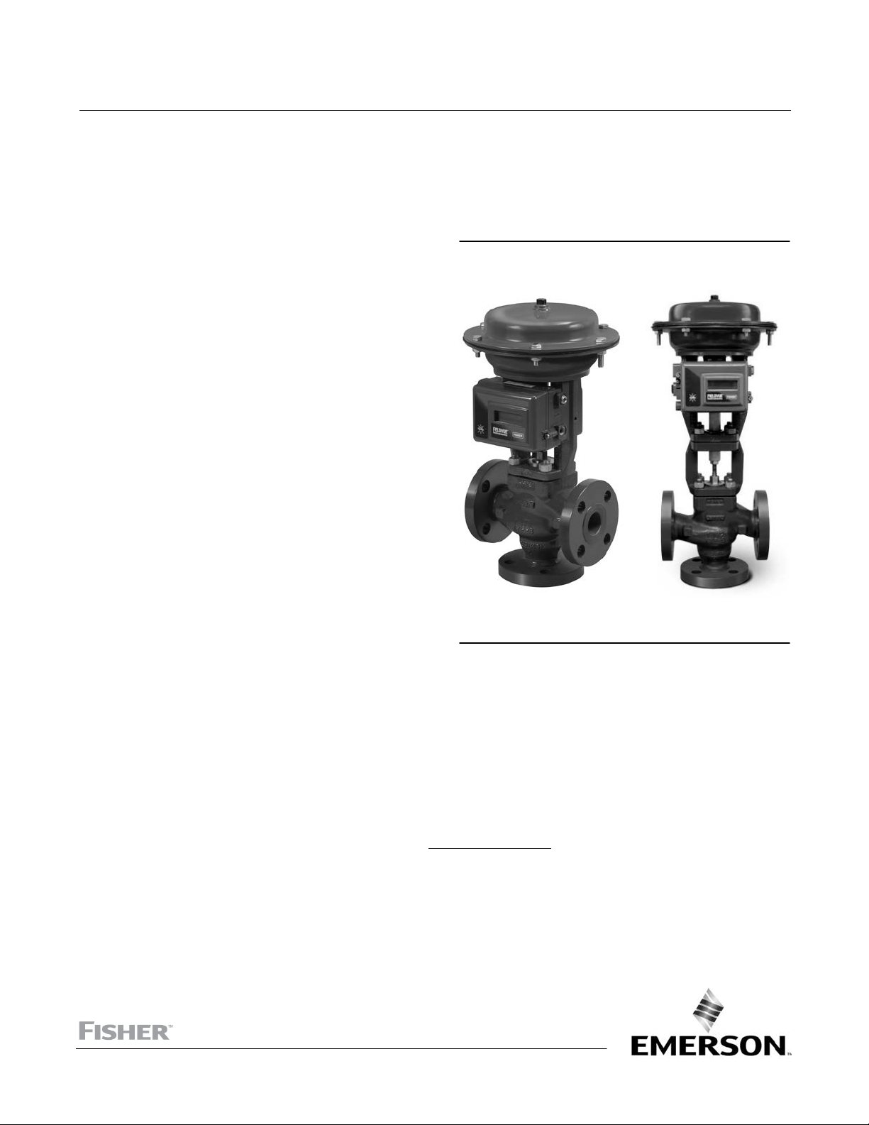
Figure 1. Fisher GX 3‐Way Control Valve, Actuator,
and FIELDVUE DVC2000 Digital Valve Controller
W9557
GX 3-WAY
X0218
GX 3-WAY
HIGH-TEMPERATURE
Introduction
Scope of Manual
This instruction manual includes installation, maintenance, and parts information for the Fisher GX 3‐Way control
valve and actuator system.
Do not install, operate, or maintain a GX 3-Way valve without being fully trained and qualified in valve, actuator, and
accessory installation, operation, and maintenance. To avoid personal injury or property damage, it is important to
carefully read, understand, and follow all the contents of this manual, including all safety cautions and warnings. If you
have any questions about these instructions, contact your Emerson sales office
proceeding.
Description
The GX 3‐Way meets the requirements of both EN and ASME standards. It is available with a complete accessory
package, including the FIELDVUE
™
DVC2000 integrated digital valve controller.
or Local Business Partner before
www.Fisher.com
GX 3-Way Valve and Actuator
July 2017
Instruction Manual
D103312X012
Table 1. Fisher GX 3‐Way Valve Specifications
Specifications EN ASME
Valve Body Sizes DN 25, 40, 50, 80, 100 NPS 1, 1‐1/2, 2, 3, 4
Pressure Rating PN 10 / 16 / 25 / 40 per EN 1092‐1 CL150 / 300 per ASME B16.34
End Connections Flanged raised face per EN 1092‐1 Flanged raised face per ASME B16.5
Valve Body Materials
Bonnet Materials 1.4409 stainless steel / CoCr‐A ASME SA351 CF3M SST / CoCr‐A
Face‐to‐Face Dimensions Based on ISA 75.08.01, see bulletin 51.1:GX 3-Way for details
Shutoff per IEC 60534‐4 and
ANSI/FCI 70‐2
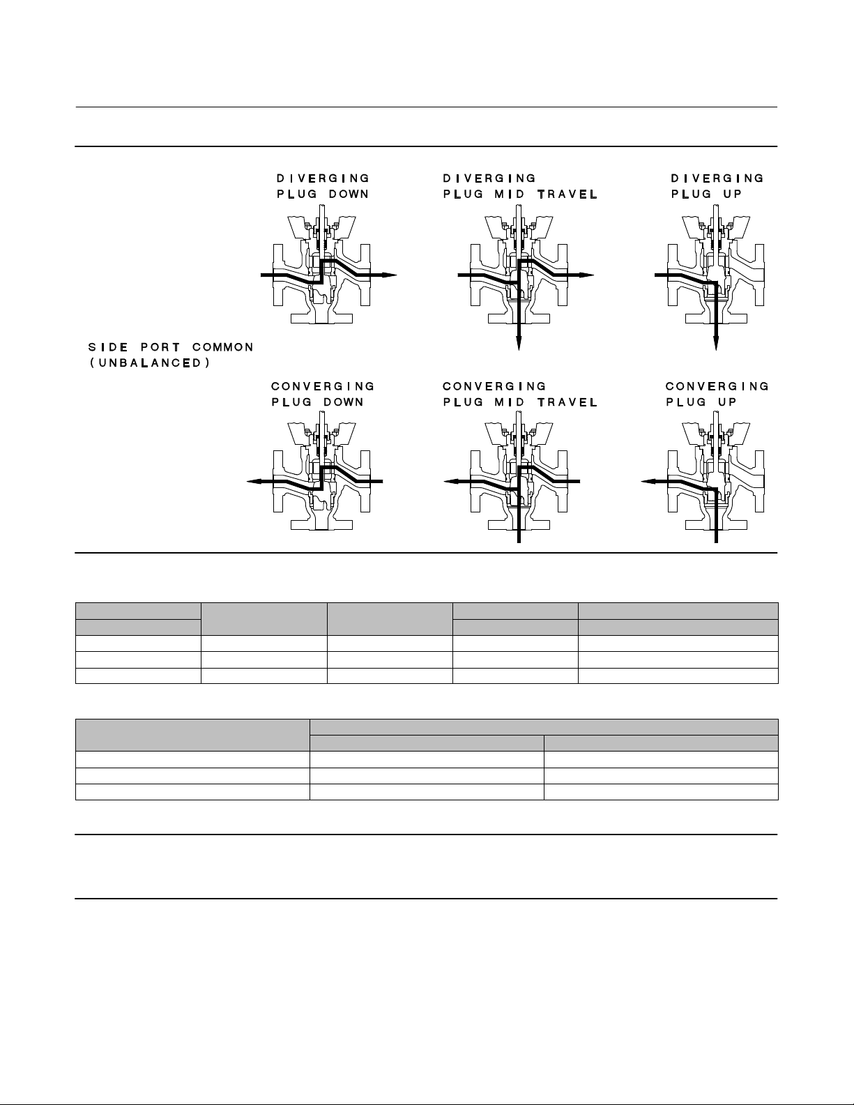
Flow Direction Converging and Diverging
Trim Style
1. Stainless steel valve body is recommended for steam service when the high temperature (HT) construction is selected.
1.4409 stainless steel ASME SA351 CF3M stainless steel
Side port common high temperature construction: Metal seat - Class IV for bottom seat, Class II for upper seat
Side‐Port Common All sizes Unbalanced Port‐Guided
Bottom‐Port Common All sizes Balanced Cage‐Guided
(1)
1.0619 steel ASME SA216 WCC steel
Metal seat ‐ Class IV (standard)
Type Plug Style Type
Educational Services
For information on available courses for the Fisher GX 3-Way control valve and actuator system, as well as a variety of
other products, contact:
Emerson Automation Solutions
Educational Services - Registration
Phone: 1-641-754-3771 or 1-800-338-8158
E-mail: education@emerson.com
emerson.com/fishervalvetraining
Valve Installation
WARNING
Always wear protective gloves, clothing, and eyewear when performing any installation operations to avoid personal
injury.
Personal injury or equipment damage caused by sudden release of pressure or bursting of pressure retaining parts might
result if service conditions exceed those for which the product was intended. To avoid injury or damage, provide a relief
valve for over pressure protection as required by government or accepted industry codes and good engineering practices.
Check with your process or safety engineer for any additional measures that must be taken to protect against process
media.
If installing into an existing application, also refer to the WARNING at the beginning of the Maintenance section in this
instruction manual.
CAUTION
This valve is intended for a specific range of pressures, temperatures and other application specifications. Applying
different pressure and temperatures to the valve could result in parts damage, malfunction of the control valve or loss of
control of the process. Do not expose this product to service conditions or variables other than those for which the product was
intended. If you are not sure what these conditions are you should contact your Emerson sales office
Partner for more complete specifications. Provide the product serial number (shown on the nameplate, figure 2) and all
other pertinent information.
or Local Business
2
Instruction Manual
D103312X012
GX 3-Way Valve and Actuator
July 2017
WARNING
If you move or work on an actuator installed on a valve with loading pressure applied, keep your hands and tools away from
the stem travel path to avoid personal injury. Be especially careful when removing the stem connector to release all loading
on the actuator stem whether it be from air pressure on the diaphragm or compression in the actuator springs. Likewise
take similar care when adjusting or removing any optional travel stop. Refer to the relevant actuator Maintenance
Instructions.
If hoisting the valve take care to prevent people from being injured in case the hoist or rigging slips. Be sure to use
adequately sized hoists and chains or slings to handle the valve.
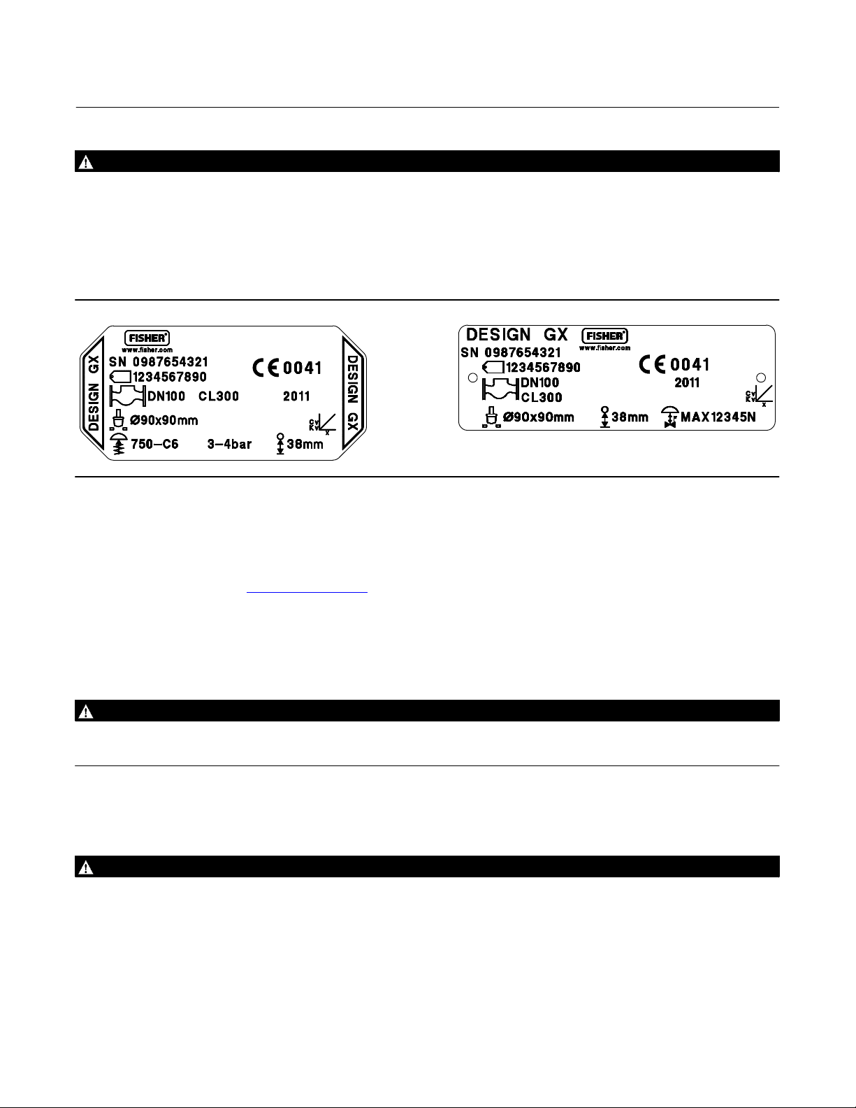
Figure 2. Fisher GX 3‐Way Nameplate (Key 35)
GE35409-D
GG12218-A
ELECTRIC ACTUATOR
1. Before installing the valve, inspect it to be certain that the valve body cavity is free of all foreign material. Clean out
all pipelines to remove scale, welding slag and other foreign material.
2. The control valve assembly may be installed in any orientation unless limited by seismic criteria. However, the
normal method is with the actuator vertical above the valve. Other positions may result in uneven trim wear, and
improper operation. With some valves, the actuator may also need to be supported when it is not vertical. For more
information, consult your Emerson sales office
or Local Business Partner. Flow through the valve must be in the
direction indicated by the flow arrow nameplate on the valve. See figures 3 and 4.
3. Use accepted piping practices when installing the valve in the pipeline. Use a suitable gasket between the valve and
the pipeline flanges.
4. If continuous operation is required during inspection or maintenance, install isolating valves on either side of the
control valve with a bypass valve to control the flow while the control valve is receiving maintenance.
WARNING
Personal injury could result from packing leakage. Valve packing is tightened before shipment; however the packing might
require some readjustment to meet specific service conditions.
Maintenance
WARNING
Avoid personal injury or property damage from sudden release of process pressure or bursting of parts. Before performing
any maintenance operations:
D Do not remove the actuator from the valve while the valve is still pressurized.
D Always wear protective gloves, clothing, and eyewear when performing any maintenance operations to avoid personal
injury.
D Disconnect any operating lines providing air pressure, electric power or a control signal to the actuator. Be sure the
actuator cannot suddenly open or close the valve.
3
GX 3-Way Valve and Actuator
July 2017
Instruction Manual
D103312X012
D Use bypass valves or completely shut off the process to isolate the valve from the process pressure. Relieve the process
pressure from all three inlets/outlet of the valve.
D Depending on the actuator construction, it will be necessary to manage the pneumatic actuator loading pressure and
any actuator spring pre‐compression. It is essential to refer to the relevant actuator instructions in this manual to
ensure safe removal of the actuator from the valve.
D Use lock‐out procedures to be sure that the above measures stay in effect while you work on the equipment.
D The valve packing box may contain process fluids that are pressurized, even when the valve has been removed from the
pipeline. Process fluids may spray out under pressure when removing the packing hardware or packing rings, or when
loosening the packing box pipe plug.
D Check with your process or safety engineer for any additional measures that must be taken to protect against process
media.
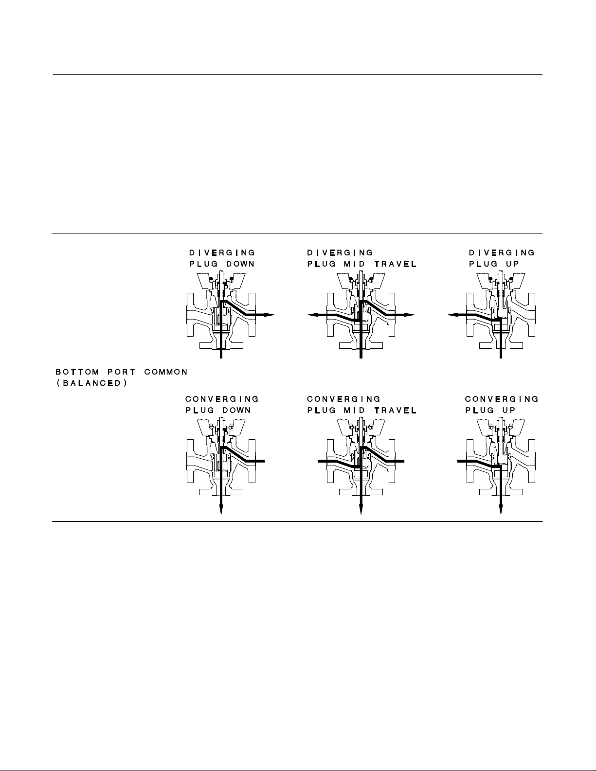
Figure 3. Fisher GX 3‐Way Valve Bottom‐Port Common Flow Direction
GE37477_FLOWDIR
4
Instruction Manual
D103312X012
Figure 4. Fisher GX 3‐Way Valve Side‐Port Common Flow Direction
GX 3-Way Valve and Actuator
July 2017
GE37477_FLOWDIR
Table 2. Fisher GX 3‐Way Rated Travel
VALVE SIZE
NPS mm mm
1, 1‐1/2 225 6 19 21
2 750 10 19 21
3, 4 750 10 38 40
ACTUATOR SIZE
NUMBER OF CASING
BOLTS
TRAVEL STEM CONNECTOR GAP SETTINGS
Table 3. Body Nut (Key 7) Torque Requirements
VALVE SIZE
DN 25 and 40 (NPS 1 and 1‐1/2) 79.8 58.9
DN 50 (NPS 2) 163 120
DN 80 and 100 (NPS 3 and 4) 282 208
NSm lbfSft
Note
Whenever a gasket seal is disturbed by removing or shifting gasketed parts, install a new gasket during reassembly. This ensures a
good gasket seal because the used gasket may not seal properly.
TORQUE
Actuator Maintenance
For electric actuators, see the supplier's instruction manual.
5

GX 3-Way Valve and Actuator
July 2017
Instruction Manual
D103312X012
The following sections provide procedures for actuator maintenance. Refer to figures 8, 11, and 13.
The actuator soft parts may require periodic replacement. This includes the diaphragm (key 10), diaphragm O-ring
(key 109), actuator rod bushing (key 19), and the actuator rod seal (key 20).
If the actuator stroking direction is unknown, refer to the nameplate on top of the actuator casing and figure 2.
Note
When the GX 3‐Way actuator is equipped with the integrated FIELDVUE DVC2000 digital valve controller (figure 1), additional
considerations may be required. Refer to the FIELDVUE DVC2000 Digital Valve Controller quick start guide, D103203X012
mounting instructions.
, for
Actuator Disassembly (For Fail‐Down Constructions, see figure 11)
1. Connect a separate air supply to the lower diaphragm casing via the air supply connection on the yoke (as shown in
figure 11) and apply sufficient air pressure to raise the valve plug/stem off the lower seat to mid‐travel.
2. Remove the stem connector nut half (key 23), stem connector bolt half (key 24), and travel indicator (key 26).
3. Push the valve plug/stem (key 3) down until it contacts the seat.
4. Loosen the locknut (key 28) and thread the lower stem connector (key 27) down until it clears the top of the valve
plug/stem (key 3).
D For HT construction, loosen locknut (key 108) and thread the stem extension (key 106) down as far as possible
(see figure 12).
5. Shut off the air pressure and disconnect the separate air supply to the lower diaphragm casing (as shown in figure
11).
WARNING
To avoid personal injury or property damage due to actuator springs (key 12) being under compression, remove the long
cap screws (key 16) last.
The upper actuator casing may remain fixed to the diaphragm and lower casing during disassembly, even if the casing cap
screws have been loosened. If this happens, the actuator springs are still under compression. The upper casing could
suddenly come loose and jump, due to the compressed energy of the springs. If the upper casing is stuck to the diaphragm
and lower casing when you begin loosening the casing cap screws, pry the casings apart with a prying tool. Always ensure
that the springs are dispersing energy and the upper casing is moving against the long bolts during disassembly.
6. Remove the short actuator casing cap screws and hex nuts (keys 17 and 18) first. Once these have been removed
from the actuator assembly, carefully remove the long actuator cap screws and hex nuts (keys 16 and 18),
alternating between them to gradually release the spring energy (compression).
7. Remove the upper diaphragm casing (key 9) and the actuator springs (key 12).
8. Lift off the actuator stem/diaphragm assembly (includes keys 22, 11, 10, 14, 13, 109, and 15) and remove the cap
screw (key 14), actuator spacer (key 13), actuator rod (key 22), and washer (key 15).
9. Replace the diaphragm (key 10), actuator rod bushing (key 19), actuator rod seal (key 20), and diaphragm O-ring
(key 109), as needed.
Actuator Disassembly (For Fail‐Up Constructions, see figure 8)
1. Connect a separate air supply to the air supply connection on the upper casing (shown in figure 8) and apply
sufficient air pressure to move the plug/stem to mid‐travel.
6

Instruction Manual
D103312X012
GX 3-Way Valve and Actuator
July 2017
2. Remove the stem connector nut half (key 23), stem connector bolt half (key 24), and travel indicator (key 26).
3. Shut off the air pressure and disconnect the air supply to the upper casing.
WARNING
To avoid personal injury or property damage due to actuator springs (key 12) being under compression, remove the long
cap screws (key 16) last.
The upper actuator casing may remain fixed to the diaphragm and lower casing during disassembly, even if the casing cap
screws have been loosened. If this happens, the actuator springs are still under compression. The upper casing could
suddenly come loose and jump, due to the compressed energy of the springs. If the upper casing is stuck to the diaphragm
and lower casing when you begin loosening the casing cap screws, pry the casings apart with a prying tool. Always ensure
that the springs are dispersing energy and the upper casing is moving against the long bolts during disassembly.
4. Remove the short actuator casing cap screws and hex nuts (keys 17 and 18) first. Once these have been removed
from the actuator assembly, carefully remove the long actuator cap screws and hex nuts (keys 16 and 18),
alternating between them to gradually release the spring energy (compression).
5. Remove the upper diaphragm casing (key 9).
6. Lift off the actuator stem/diaphragm assembly (includes keys 22, 11, 10, 14, 13, 109, and 15) and remove the cap
screw (key 14), actuator spacer (key 13), actuator rod (key 22), and washer (key 15).
7. Remove the actuator springs (key 12).
8. Replace the diaphragm (key 10), actuator rod bushing (key 19), actuator rod seal (key 20), and diaphragm O-ring
(key 109), as needed.
Actuator Assembly (For Fail‐Down Constructions, see figure 11)
1. Install the diaphragm (key 10) on the diaphragm plate (key 11). Insert the cap screw (key 14) through the actuator
spacer (key 13) and place this assembly through the diaphragm/diaphragm plate assembly.
2. Place the diaphragm O-ring (key 109) and the washer (key 15) over the center hole of the diaphragm, so that the
convex part of the washer is facing down toward the diaphragm and contains the O-ring. Ensure the convex part of
the washer is guided in the diaphragm center hole as shown in figure 11.
3. Screw the actuator rod (key 22) onto the cap screw (key 14) and torque to 80.0 NSm (59.1 lbfSft). Install the
actuator stem/diaphragm assembly back into the actuator yoke (key 8).
4. Place the actuator springs (key 12) onto the spring locators in the diaphragm plate (key 11).
5. Install the upper diaphragm casing (key 9) so that the ribs on the top of the upper diaphragm casing are
perpendicular with the yoke legs.
6. Install the 2 long cap screws (key 16) and hex nuts (key 18) 180 degrees apart from each other and in line with the
actuator yoke legs.
7. Tighten the long cap screws (key 16) and hex nuts (key 18), alternating between them to gradually compress the
springs, until the two casing halves and diaphragm touch.
8. Install the remaining short cap screws (key 17) and hex nuts (key 18) to the casing.
9. Tighten the actuator casing cap screws evenly using a cross‐tightening procedure. Torque to 55 NSm (40 lbfSft).
10. If you had previously removed the actuator assembly from the valve, place the actuator assembly back onto the
valve body (key 1) or yoke extension (key 105, figure 12) for HT constructions. Install the four body nuts (key 7), but
tighten them only finger‐tight.
11. Connect a separate air supply to the actuator air supply connection (as shown on the yoke in figure 11) and apply
sufficient air pressure to raise the actuator rod (key 22) to the travel stop.
12. Tighten the body nuts (key 7) evenly using a cross‐tightening procedure. See table 3 for torque requirements.
7

GX 3-Way Valve and Actuator
July 2017
Instruction Manual
D103312X012
D For HT constructions, the valve body nuts (key 7) are tightened at the valve body (key 1) and at the top of the
yoke extension (key 105), see figure 12.
13. With the valve plug/stem (key 3) on the lower seat, thread the lower stem connector (key 27) up to match the gap
setting between the actuator rod and stem adjuster nut specified in table 2. Thread the locknut (key 28) up against
the stem adjustor nut and tighten to a torque of 48 NSm (35 lbfSft) for the 10mm stems or 175 NSm (129 lbfSft) for
14mm stems.
D For HT constructions see figure 12. With the valve plug/stem (key 3) on the lower seat, thread the stem
extension (key 106) up to match the gap setting between the actuator rod and stem extension specified in
table 2. Thread the locknut (key 108) up against the stem extension and tighten to a torque of 48 N•m (35
lbf•ft) for the 10mm stems or 175 N•m (129 lbf•ft) for 14mm stems.
14. Stroke the actuator rod until it contacts the lower stem connector (key 27), or the stem extension (key 106, figure
12) for HT construction, and install the stem connector halves and travel indicator (keys 23, 24, and 26) with the
cap screws (key 25). Install the stem connector halves in the proper orientation so that when looking at the inside of
the stem connector halves, the flats are down and the beveled surfaces are up.
15. Align the pointer of the travel indicator (key 26) with the appropriate mark on the travel scale.
16. Tighten the stem connector cap screws (key 25) to 35 NSm (26 lbfSft).
17. Release the actuator pressure.
Actuator Assembly (For Fail‐Up Constructions, see figure 8)
1. Position the upper diaphragm casing (key 9) upside down on the bench so that it lays flat and not off balance.
Note
If converting from fail‐down to fail‐up action, first move the vent cap (key 21) from the top of the casing (see figure 8) and thread
into the air supply connection on the yoke leg (see figure 11).
2. Install the diaphragm (key 10) on the diaphragm plate (key 11). Place the diaphragm O-ring (key 109) and the
washer (key 15) over the center hole of the diaphragm, so that the convex part of the washer is facing down toward
the diaphragm and contains the O-ring. Ensure the convex part of the washer is guided in the diaphragm center
hole as shown in figure 8.
3. Insert the cap screw (key 14) through the washer and diaphragm, install the actuator spacer (key 13), and screw the
actuator rod (key 22) onto the cap screw (key 14) finger‐tight.
4. Radially align the spring locators in the diaphragm plate assembly (key 11) with the casing cap screw holes in the
diaphragm (key 10). This will ensure that the springs do not cover the air path in the yoke.
5. Torque the cap screw (key 14) to the actuator rod (key 22) to 80.0 NSm (59.1 lbfSft) and lay this assembly into the
upper diaphragm casing (key 9).
6. Place the actuator springs (key 12) onto the spring locators in the diaphragm plate (key 11).
7. Set the actuator yoke (key 8) down onto the assembly that is resting in the upper diaphragm casing (key 9) so that
the yoke legs are perpendicular with the ribs on the top of the upper diaphragm casing (key 9).
8. Install the 2 long cap screws (key 16) and hex nuts (key 18) 180 degrees apart from each other and in line with the
actuator yoke legs.
9. Tighten the long cap screws (key 16) and hex nuts (key 18), alternating between them to gradually compress the
springs, until the two casing halves and diaphragm touch.
10. Install the remaining short cap screws (key 17) and hex nuts (key 18) to the casing.
11. Tighten the actuator casing cap screws evenly using a cross‐tightening procedure. Torque to 55 NSm (40 lbfSft).
8

Instruction Manual
D103312X012
12. If you had previously removed the actuator assembly from the valve, place the actuator assembly back onto the
valve body (key 1) or yoke extension (key 105, figure 12) for HT construction. Install the body nuts (key 7) and
tighten evenly using a cross‐tightening procedure. See table 3 for torque requirements.
D For HT constructions, see figure 12. Ensure the valve body nuts (key 7) are tightened at the valve body (key 1)
and at the top of the yoke extension (key 105).
13. With the valve plug/stem (key 3) on the lower seat, thread the lower stem connector (key 27) up to match the gap
setting between the actuator rod and stem adjustor nut specified in table 2. Thread the locknut (key 28) up against
the stem locknut and tighten to a torque of 48 NSm (35 lbfSft) for 10mm stems or 175 NSm (129 lbfSft) for 14mm
stems.
D For HT constructions see figure 12. With the valve plug/stem (key 3) on the lower seat, thread the stem
extension (key 106) up to match the gap setting between the actuator rod and stem extension specified in
table 2. Thread the locknut (key 108) up against the stem extension and tighten to a torque of 48 N•m (35
lbf•ft) for the 10mm stems or 175 N•m (129 lbf•ft) for 14mm stems.
14. Stroke the actuator rod until it contacts the lower stem connector (key 27), or stem extension (key 106, figure 12),
and install the stem connector halves and travel indicator (keys 23, 24, and 26) with the cap screws (key 25). Install
the stem connector halves in the proper orientation so that when looking at the inside of the stem connector
halves, the flats are down and the beveled surfaces are up.
15. Align the pointer of the travel indicator (key 26) with the appropriate mark on the travel scale.
16. Tighten the stem connector cap screws (key 25) to 35 NSm (26 lbfSft).
GX 3-Way Valve and Actuator
July 2017
Note
For fail‐up action, the air supply tubing must be connected to the actuator upper casing at the air supply connection, see figure 8.
(If converting from fail‐down to fail‐up, the tubing will need to be re‐routed to this location).
Packing Maintenance
Key numbers refer to figure 7.
Packing Adjustment
For ENVIRO-SEAL™ spring‐loaded single PTFE V‐ring packing (figure 7) or for ENVIRO-SEAL graphite ULF packing (figure
7), the Belleville spring pack (key 34) maintains a sealing force on the packing. If leakage is detected around the
packing follower (key 29) check to be sure that the packing follower (key 29) is tight. Using a wrench, tighten the
packing follower (key 29) in 1/4 turn intervals until the leakage is stopped. If leakage cannot be stopped in this
manner, proceed to the Replacing Packing section in this manual.
Replacing Packing (Pneumatic Actuators)
Isolate the control valve from the line pressure, release pressure from all three inlets/outlets of the valve body and
drain the process media from the valve. Shut off all pressure lines to the actuator and release all pressure from the
actuator. Use lock‐out procedures to ensure that the above measures stay in effect while you work on the equipment.
1. For fail‐down constructions, as shown in figure 11:
a. Connect a separate air supply to the lower diaphragm casing via the air supply connection on the yoke (as shown
in figure 11) and apply sufficient air pressure to raise the valve plug/stem off the lower seat to mid travel.
9
 Loading...