

Fisher Guide: FIELDVUE Instruments - A Planning Guide for Effective use - HART Implemenations Manuals & Guides
Page 1

FIELDVUE™ Instruments
A Planning Guide for Effective Use
HART® Implementations
February 2020
D103278X012
You've purchased a FIELDVUE instrument.....Now what???
How do you get the most value out of it?
Where do you start?
What's the best way to install it?
Where do you set your alerts?
Online/offline?
Diagnostics? When? How?
The answer is....... Start out with a good foundation and build on it!
X1182-1
X0379
W8858
www.Fisher.com
Page 2

Page 3

I. Introduction 1....................................................................
1. Scope 1..................................................................
™
2. Plantweb
Digital Ecosystem Discussion 1.....................................
3. FIELDVUE Instrument Background 2..........................................
4. ValveLink™ Software Background 3...........................................
5. ABC Asset Criticality Assessment 3...........................................
II.Startup and Commissioning 4.....................................................
1. Baseline Data Gathering 8..................................................
Using ValveLink Software or ValveLink SNAP-ON™ for AMS Device Manager 8....
Using AMS Trex or 475 Communicator with ValveLink Mobile App 9...........
Using AMS Trex or 475 Communicator with HART App 9.....................
III.Normal Operations 10..........................................................
1. Using ValveLink Software in Conjunction with
Multiplexers or ValveLink Integrated System
(ex. DeltaV™ or Ovation™ with AMS) 10........................................
2. Roving Laptop Using ValveLink Solo or
ValveLink SNAP‐ON for AMS Device Manager 11................................
3. Valves with AMS Trex or 475 Communicator Monitoring Only with
ValveLink Mobile App 12...................................................
4. Valves with AMS Trex or 475 Communicator Monitoring Only with HART App 13.....
IV.Turnarounds 14................................................................
Before Turnarounds
After Turnaround Begins
After Turnaround
V.Summary 15...................................................................
VI.Appendix A Alerts 16...........................................................
VII.Appendix B Diagnostics 20......................................................
1. FIELDVUE Diagnostics Overview 20...........................................
2. Performance Diagnostics Overview 21........................................
3. Performance Diagnostics - Test Details (In Service Testing) 21....................
4. Advanced Diagnostics - Test Details (Out of Service Testing) 28...................
5. Advanced Diagnostics - Look and Feel 31......................................
VIII.Appendix C Value‐Add Features 32..............................................
Page 4

Page 5

I. Introduction
1. Scope
The purpose of this guide is to help you develop a plan to use the FIELDVUE instrument more effectively.
We have made every effort to present meaningful and realistic information. The topic area is so broad that it is
difficult to cover all possibilities in a single comprehensive document. However, the contents of this document
should provoke thought process and work practice changes surrounding the full value of a digital technology coupled
with state‐of‐the‐art diagnostics.
This guide begins with a short discussion of the FIELDVUE instrument product line and the associated ValveLink
software tools, features and the functionalities they encompass. This is followed by methods to effectively implement
FIELDVUE instruments in the following situations:
Startup and commissioning
Normal operations
Turnarounds
These sections are intended to provide you with suggested initial settings. Also included are recommended changes
and/or additions to existing work practices that allow you to realize the full value of FIELDVUE instrument diagnostics.
A more detailed discussion of alerts and diagnostics, examples of specific value‐add features such as scheduler, alert
log, batch runner, etc., and troubleshooting can be found in the appendices.
If you have any questions regarding these subjects, please contact your Emerson sales office
.
2. Plantweb Digital Ecosystem Discussion
Plantweb digital ecosystem leverages the power of intelligence in field devices to securely improve the Industrial
Internet of Things (IoT) with measurable business performance improvement. The digital intelligence in the field
devices is used to provide the data for predictive diagnostics and to improve performance of final control elements
and measurement instruments.
The basis for the Fisher design philosophy, or what makes for a good control valve, is superior dynamic
responsiveness. The key characteristics of superior dynamic performance are:
Does the valve react to small changes in input signal (1/4%-1%)?
Does the valve move fast enough?
Does the movement provide the right installed gain for the PID process loop tuning to work over the operating
flow range?
The ability to “tune” FIELDVUE instruments to the valve/actuator assembly provides the required dynamic
responsiveness which:
allows operations to push setpoints closer to constraints,
allows for more aggressive PID tuning,
allows continuous use of Model Predictive or Advanced Control strategies,
drives more efficient plant operation, increased throughput, lower energy and utility costs, better quality, and
less rework.
1
Page 6

The diagnostics capability of the FIELDVUE instrument optimizes control valve assets and provides:
increased availability,
increased uptime,
decreased unscheduled outages for control valve problems,
faster problem identification and resolution,
increased maintenance effectiveness,
lower maintenance costs by pinpointing problems and eliminating unnecessary expenditures on parts, labor, or
downtime, and
Increased plant safety.
It is this combination of expertise in process control and control valve design, digital intelligence in the positioner,
and open communications protocols such as HART and FOUNDATION™ fieldbus, that deliver a positioner capable of
superior dynamic responsiveness as well as a “data server” capable of diagnostics.
3. FIELDVUE Instrument Background
FIELDVUE instruments are microprocessor based digital valve controllers. These digital valve controllers have the
ability to precisely position a control valve assembly using a setpoint received from a control system. More than just a
digital positioner, they also perform control valve diagnostics, alert you of critical information before it affects the
process, and communicate using HART, Fieldbus, or PROFIBUS protocol.
The first generation FIELDVUE instrument was the DVC5000 (HART) released in 1994. This was the first loop powered
digital valve controller available on the market. The next release was the DVC5000f (Fieldbus) in 1998. The third
generation instrument, the DVC6000 (HART) was released in 2000 and included many enhancements in control and
diagnostics functionality. The addition of multiple sensors and double-acting capability gave the instruments
industry‐leading functionalities. The DVC6000f (Fieldbus) was released in 2004 and added Fieldbus communications
as well as ground breaking control performance. Options for remote mount travel sensor and extreme temperature
construction are also available.
The DVC2000 was released in 2004. New functions included the use of a local user interface, multilingual display,
integrated limit switches, position transmitter, and non-contact feedback.
The fourth generation instruments, the DVC6200 and DVC6200f, were released in 2009, while the DVC6200p
(PROFIBUS) was released in 2012. These instruments incorporate the linkage-less non contact feedback design to
make a good product even better. New functions include the position transmitter or 1 switch, 316 SST model,
remote unit, and HART 7 communication option.
2
Page 7

4. ValveLink Software Background
ValveLink software is the companion tool used to get the most value out of FIELDVUE positioning instruments. While
there are a variety of packages available in the industry with the ability to configure, calibrate and view alerts, only
ValveLink software can perform valve assembly diagnostics.
ValveLink software has the ability to be installed and used in various forms:
ValveLink Solo working with a HART multiplexer, HART modem or F
ValveLink SNAP‐ON for AMS Device Manager
ValveLink DTM
ValveLink PLUG‐IN for PRM
ValveLink Mobile for AMS Trex or 475 Communicator
You will receive the most value from integrated HART or Fieldbus installations. The preferred method is to have a
maintenance station on an Emerson system, such as DeltaV, or Ovation, with AMS Device Manager, due to the
advanced integration, the ability to easily view needed information, and the ability to automate batch features.
®
OUNDATION fieldbus
5. ABC Asset Criticality Assessment
All assets in the plant are not equal. Final control assemblies, transmitters, sensors, pumps, and other process control
equipment have different degrees of criticality. The results of a criticality assessment can provide valuable
information that can be used to determine how each asset should be monitored and maintained. Typically A rated
assets are the most critical and have the most effect on plant operations. They require more monitoring and receive
the highest work order priority. If the final control assembly is an A asset, it should be tiered to a PD level. B assets are
of lesser criticality. The B critical final control element is typically tiered to an AD level. The ABC ranking should enable
you to define the critical valve assemblies in your plant, the alerts required, and the frequency for inspecting these
assets. Emerson’s Asset Management can help you get started with this assessment in your plant. For more
information, contact your Emerson sales office.
3
Page 8

II. Startup and Commissioning
The following steps are recommended guidelines for the setup, calibration, and configuration of a FIELDVUE
instrument. These steps can be performed using AMS Device Manager, ValveLink software, AMS Trex or 475
Communicator with ValveLink Mobile or DD, and most other HART host tools that use DD technology:
General recommendations to successfully set up FIELDVUE Instruments are:
- Always use the Setup Wizard (Do not use the Setup Wizard after the instrument is setup on a valve
assembly. You could accidentally reset the unit to factory defaults, erasing all of the custom configuration
that is in the instrument)
- Always try to use Auto Travel Calibration (Auto calibration of travel is always required if the instrument is
removed from the valve assembly for maintenance purposes)
- Always enable the Alert Record in the instrument (Clear the Alert Record after commissioning)
Create and follow a startup and commissioning plan. At a minimum, the plan should include the following:
- Review your application - gather valve data, serial cards, etc.
- Determine cutoffs/limits and travel alerts, if applicable.
- Mount instrument properly
- Run Setup Wizard
Run Performance Tuner if actuator was not listed in Setup Wizard
- Enable below Alerts for visibility to basic valve assembly health information:
Travel Deviation: 5% for 10 seconds
Supply Pressure: 3 psi above upper benchset for spring & diaphragm, 10 psi below nominal instrument
air supply for piston actuators
Drive Signal
- Reset Cycle Counter and Travel Accumulator to Zero (0)
- Ensure Valve Alerts are enabled, this will allow alerts to be written to the instrument alert record (on‐board
alert storage utility)
Set Instrument Date & Time
Clear Alert Event Record
Enable Triggered Profile on PD units
Use Travel Deviation as the Triggered Event for throttling control valves
Use Collection Variables of Travel Set Point, Travel, Drive Signal, and Supply
Use Trigger Record Length of 60 seconds. The DVC6200/DVC6000 can hold approximately 20 minutes
of triggered data sets.
Note
Triggered data in the device will show up on the alert record as Diagnostic Data Available.
When alert scanning using a DCS with HART cards or multiplexers, the following additional settings are
recommended:
- Device Alerts
- ValveLink SNAP‐ON, scan all valves as fast as possible, A critical valves more often than
B and C critical valves
- ValveLink Solo automatically scans at maximum speed possible for system
- PD One Button Sweep using Scheduler
A critical valves, one per week
B critical valves, one every two weeks
C critical valves, once a month
4
Page 9

- PD Friction using Scheduler (ensure upper and lower friction values are set up in PD Diagnostic Trends of
Friction
A critical valves, two per month
B critical valves, one per month
The following table provides a more detailed list of recommended initial settings. These are “best practices”, which
have been derived from the current installed base. They are general guidelines that may need to be modified based
upon the specific application. When starting with an alert strategy, keep the number of alerts enabled to a minimum.
Start with Travel Deviation, Supply Pressure Low, and Drive Signal Out of Range. These alerts are the most critical for
throttling control valves. If you set too many alerts to start with, they may be seen as nuisance alerts and have a
tendency to be ignored.
DVC6200 (HW2) Parameters
Setup Parameter Factory Default Alert Settings
Control Mode Analog (RSP) Analog (RSP)
Restart Control Mode Resume Last Resume Last
Burst Mode Enabled No No Set to Yes if a Tri‐Loop is used
Burst Mode Command Loop Current/PV/SV/TV/QV Loop Current/PV/SV/TV/QV
HART Tag As Specified on Order Fill in Plant Information Tag from DCS, P&ID, etc.
Message Blank Fill in Plant Information
Descriptor Blank Fill in Plant Information
Date Factory Calibration Date Set to Current Date
Valve Serial Number Blank Fill in Valve Serial Number
Polling Address 0 0
Max Supply Pressure 1.378 Bar 1.378 Bar
Feedback Connection Default Array Default Array Can be corrected to actual array
Zero Power Condition Valve Closed Valve Closed Determined by Setup Wizard
Travel Sensor Motion
Analog Input Units mA mA % for DeltaV
Analog In Range High 20 mA 20 mA 100% for DeltaV
Analog In Range Low 4.0 mA 4.0 mA 0% for DeltaV
Pressure Units Bar Bar End User to Determine
Temperature Units C C End User to Determine
Tuning Set H H Determined by Setup Wizard
Input Characteristics Linear Linear
Set Point Filter Lag Time 0 Sec 0 Sec
High Limit/Cutoff Select Hard Cutoff Hard Cutoff End User to Determine
Low Limit/Cutoff Select Hard Cutoff Hard Cutoff End User to Determine
High Limit/Cutoff Point 99.46% 99.46%
Clockwise/Away from Top of
Instrument
- Continued -
Recommended Initial
Alert Settings
Clockwise/Away from Top of
Instrument
Notes
Should be 5 psi above upper
benchset or actuator Maximum or
digital valve controller Maximum.
Determined by Setup Wizard
This parameter is dependent on
service and trim type eg. CAVIII or
standard. For example in BFP
Recirc with a Reverse Acting valve
you might want this set at 92%
whereas for standard trim 99.46%
might be acceptable
5
Page 10

DVC6200 (HW2) Parameters (continued)
Setup Parameter Factory Default Alert Settings
Low Limit/Cutoff Point 0.50% 0.50%
SP Rate Open 0 %/sec 0 %/sec
SP Rate Closed 0 %/sec 0 %/sec
Integral Enabled Enabled Enabled
Integral Gain 10 repeats/minute 10 repeats/minute
Integral Deadband* 0.26% 0.26% *See table below (page 7)
Travel Hi/Lo Alert Enabled Disabled Disabled End User to Determine
Travel Hi Hi/Lo Lo Alert Enabled Disabled Disabled End User to Determine
Travel Alert High Point 125% 125% End User to Determine
Travel Alert Low Point -25% -25% End User to Determine
Travel Alert High‐High Point 125% 125% End User to Determine
Travel Alert Low‐Low Point -25% -25% End User to Determine
Travel Alert Deadband 1% 3%
Travel Deviation Alert Enabled Yes Yes
Travel Deviation Alert Point 5% 5%
Travel Deviation Time** 10 sec 5 sec **See table below (page 7)
Pressure Deviation Alert Enable Yes Yes
Pressure Deviation Alert Point 0.345 bar 5 psi
Pressure Deviation Time 5 sec 10 sec
Cycle Counter Alert Enable No No
Cycle Counter Alert Point 500000 500000
Cycle Cnt/Tvl Accum Deadband 1% 3%
Cycle Counter 0 0 Verify 0 on initial setup
Travel Accumulator Alert Point 2147483647 500000
Travel Accumulator Deadband 1% 3%
Travel Accumulator 0 0 Verify 0 on initial setup.
Local Autocal Button Enabled Enabled
- Continued -
Recommended Initial
Alert Settings
Notes
This parameter is dependent on
service and trim type eg. CAVIII or
standard. For example in BFP
Recirc with a Direct Acting valve
you might want this set at 12%
whereas for standard trim 0.5%
might be acceptable.
This is a good tool to track
problems. The end user needs to
keep track of problems such as
packing leaks, travel sensor
failures, actuator diaphragm
failures, etc. Upon the first
problem showing up, this number
needs to be recorded in the
CMMS or AMS and reset. Repair
the problem and record the
number when the next problem
occurs. This will give a history of
good data that will allow us to
enable this alarm and then
generate a work order to address
the problem before it fails.
6
Page 11

DVC6200 (HW2) Parameters (continued)
2
2
2
2
Setup Parameter Factory Default Alert Settings
Supply Pressure Alert Enable Yes Yes
Supply Pressure Alert Point 0.345 bar 3 psi above upper benchset.
Drive Signal Alert Enable Yes Yes
Inst Time Invalid Enable No No
Cal in Progress Enable No No
Autocal in Progress Enable No No
Diag in Progress Enable No No
Diag Data Avail Enable No Yes
Integrator Sat High Enable No No
Integrator Sat Low Enable No No
Pressure Fallback Enable Yes Yes
Recommended Initial
Alert Settings
Notes
10 psi below nominal for piston
actuators.
*Integrator - Enabled and configured as follows:
Integrator Parameter PTFE Packing Graphite Packing
Integrator Dead Zone 0.26% 0.5% 0.7%
Enviro-Seal PTFE and
Graphite ULF Packing
**Travel Deviation Alert - Enabled and configured as follows:
Actuator Diaphragm Area PTFE Packing Graphite Packing
<= 100 in
> 100 in2 to <= 200 in
> 200 in2 to <= 300 in
> 300 in
Alert enabled
Alert Point = 2%
Alert Time = 2 sec
Alert enabled
Alert Point = 2%
Alert Time = 2 sec
Alert enabled
Alert Point = 3%
Alert Time = 5 sec
Alert enabled
Alert Point = 3%
Alert Time = 5 sec
Alert enabled
Alert Point = 3%
Alert Time = 2 sec
Alert enabled
Alert Point = 3%
Alert Time = 5 sec
Alert enabled
Alert Point = 5%
Alert Time = 8 sec
Alert enabled
Alert Point = 5%
Alert Time = 10 sec
Notes:
1. Travel Deviation Alert Point % and Travel Deviation Time set to around twice to three times what the valve's response when its new and
healthy.
2. Alternatives are to use the step response test to determine the time it normally takes for a 5% step and then set the Travel Deviation Time
to 2 times that value. Another option would be to use twice the T63 time
Enviro-Seal PTFE and
Graphite ULF Packing
Alert enabled
Alert Point = 5% Alert
Alert Time = 3 sec
Alert enabled
Alert Point = 5% Alert
Alert Time = 5 sec
Alert enabled
Alert Point = 5 % Alert
Alert Time = 10 sec
Alert enabled
Alert Point = 5 % Alert
Alert Time = 10 sec
7
Page 12

1. Baseline Data Gathering Procedures
It is important to get a good set of baseline data. This accomplishes two critical tasks: it ensures that the current
operating state of the control valve assembly is correct; and when a control valve has a problem the current data can
be compared to the baseline data to quickly pinpoint the issue. Valve outages can then be planned with the correct
parts, tools, and manpower. Most importantly, impact on the cost of operations will be minimized.
Using ValveLink Software or ValveLink SNAP-ON for AMS
Take baseline data:
1. Import valve “birth certificate” if purchased from factory
2. Fill out valve and actuator spec sheets under Detailed Setup of ValveLink software. (Factory assemblies have
been shipping with the spec sheet stored in the instrument since 2008).
3. After spec sheet is verified, read instrument and upload information into Database Dataset, save Dataset.
4. If HC, AD, or PD, run Status Monitor at 4, 12, and 20 mA (or 0%, 50%, and 100% input signal) with digital valve
controller In Service and save each dataset.
5. If AD/PD
5.1. Valve Step Response (0-100-0 Step Test)
5.2. Valve Step Response (Performance Test)
5.3. Total Dynamic Scan (DVC6200, DVC6000 or DVC2000)
5.4. Valve Signature, Drive Signal, Dynamic Error Band (DVC5000)
5.5. One Button Sweep (PD only)
5.6. Run Valve Friction diagnostic (PD only)
6. Make sure the Alert Record is enabled and clear.
8
Page 13

Using AMS Trex or 475 Communicator with ValveLink Mobile App
Take baseline data:
1. Fill out or verify valve and actuator spec sheets under Setup Icon of ValveLink Mobile software.
2. Save Detailed Setup under Setup Icon.
3. Under Status Icon, if HC, AD or PD run Status Monitor at 4, 12, and 20 mA (or 0%, 50%, and 100% input signal)
with digital valve controller In Service and save each dataset.
4. If AD/PD
4.1. Valve Step Response (Stroking Time Test)
4.2. Valve Step Response (Performance Test)
4.3. Total Scan (DVC6200, DVC6000, or DVC2000 instrument)
4.4. One Button Sweep (PD Only)
Note
ValveLink Mobile data can be imported to ValveLink Solo for more detailed analysis.
Using AMS Trex or 475 Communicator with HART Application App
Take baseline data:
Using the AMS Trex or 475 Communicator (HART Application overview screen) at 12 mA (or 50% input signal), copy
the below data into the computerized maintenance management system (CMMS):
1. Analog In
2. Valve Setpoint
3. Travel
4. Drive Signal
5. Pressures
5.1. Output A
5.2. Output B (double-acting piston)
5.3. A-B
5.4. Supply (AD or PD only)
6. Make sure the Alert Record is enabled and clear.
9
Page 14

III. Normal Operations
The goal is to move away from preventative maintenance tasks (PMs) into a predictive maintenance (PdM) mode
where we rely fully on the instrument to inform you of a pending issue. If there are no active alerts, there should be no
maintenance. If an alert is active, maintenance activities should be planned based upon the criticality of the control
valve application and the alert.
1. Using ValveLink Software in Conjunction with Multiplexers or
ValveLink Integrated System (ex. DeltaV or Ovation with AMS)
Configure the Alert Monitor to monitor all valves based on the criticality ranking of the valve. On PD units, setup
the ValveLink Scheduler to run a PD One Button Sweep and Valve Friction test on a periodic basis based on
criticality ranking.
HART Alert Troubleshooting and Correction
Alerts such as Travel Sensor Fail require a specific course of action like changing the feedback potentiometer on
a DVC6000 or checking the wiring on the DVC6205. Refer to Appendix A for a list of these alerts.
1. Other alerts such as the Travel Deviation Alert can be caused by many things and require a systematic
approach to determining what the exact problem is. A recommended approach is:
1.1. Run Status Monitor at the current operating position. Check Supply Pressure, Drive Signal, and Travel
Pressure State.
1.2. Compare current to baseline values to try to identify the problem. Check the ValveLink Alerts page to
see how the current Active Alert values compare with the Alert Point.
1.3. If unit is PD, check for triggered profile.
1.4. Correct any problems discovered.
1.5. If problems cannot be solved continue on with step 2. Use of PD and step 3. Use of AD.
2. Use of PD
2.1 Run One Button Sweep before performing any other diagnostic analysis.
2.2 Correct the problems identified by One Button Sweep.
2.3 If One Button Sweep does not clearly determine the problem, run a Valve Friction Test. Identify any
problems and correct.
2.4 If problems cannot be determined continue on with step 3. Use of AD.
3. Use of AD
3.1 Contact operations to have the valve taken out of service if possible.
3.2 DVC6200/ DVC6000 / DVC2000 - Perform a Total Scan and compare results with baseline results.
3.3 DVC5000 - Perform a Valve Signature, Drive Signal and Dynamic Error Band test and compare -
results with baseline data.
3.4 Determine the problem and correct it.
4. When the problem is corrected, reset the instrument Date & Time if required and Clear the Instrument Alert
Record.
5. If the problem still cannot be determined, contact your nearest Emerson sales office or Life Cycles Services
Center for support.
10
Page 15

2. Roving Laptop Using ValveLink Solo or
ValveLink SNAP‐ON for AMS
1. Set up routes to periodically monitor control valves.
2. Read the instrument Alert Record periodically with the laptop.
- Monitoring frequency needs to be determined through a Criticality Ranking of all control valves.
- Critical valves should be monitored at least 1x per week. Other valves may be monitored monthly,
- quarterly, semi‐annually, etc. depending upon their Criticality Ranking.
3. If the Alert Record is clear, move to the next valve in the route.
OR:
If the Alert Record is not clear, perform the following steps for HART Alert‐Troubleshooting and Correction:
1. Alerts such as Travel Sensor Fail require a specific course of action like changing the feedback potentiometer
on a DVC6000 or checking the wiring on the DVC6205. Refer to Appendix A for a list of these alerts.
2. Other alerts such as the Travel Deviation Alert can be caused by many things and requires a systematic
approach to determining what the exact problem is. A recommended approach is:
2.1. Run Status Monitor at the current operating position. Check Supply Pressure, Drive Signal, and Travel
Pressure State.
2.2. Compare current to baseline values to try to identify the problem. Check the ValveLink Alerts page to
see how the current Active Alert values compare with the Alert Point.
2.3. If unit is PD, check for triggered profile.
2.4. Correct any problems discovered.
2.5. If problems cannot be solved continue on with step 3. Use of PD, or step 4. Use of AD.
3. Use of PD
3.1. Run One Button Sweep before performing any other diagnostic analysis.
3.2. Correct the problems identified by One Button Sweep.
3.3. If One Button Sweep does not clearly determine the problem, run a Valve Friction Test. Identify any
problems and correct.
3.4. If problems cannot be determined continue on with step 4. Use of AD.
4. Use of AD
4.1. Contact operations to have the valve taken out of service if possible.
4.2. DVC6200 / DVC6000 / DVC2000 - Perform a Total Scan and compare results with baseline results.
4.3. DVC5000 - Perform a Valve Signature, Drive Signal and Dynamic Error Band test and compare
results with baseline data.
4.4. Determine the problem and correct.
5. When the problem is corrected, reset the instrument Date & Time if required and Clear the Instrument Alert
Record.
6. If the problem still cannot be determined, contact your nearest Emerson sales office or Life Cycle Services
Center for support.
11
Page 16

3. Valves with AMS Trex or 475 Communicator
Monitoring Only with ValveLink Mobile App
1. Set up routes to periodically monitor control valves.
2. Read the instrument Status Alerts periodically with the Communicator's ValveLink Mobile App.
- Monitoring frequency needs to be determined through a Criticality Ranking of all control valves.
- Critical valves should be monitored at least 1x per week. Other valves may be monitored monthly,
- quarterly, semi‐annually, etc. depending upon their Criticality Ranking.
3. If the Status Alerts are clear, move to the next valve in the route.
OR:
If an Alert is active on the Status Alerts screen, perform the following steps for HART Alert Troubleshooting and
Correction:
1. Alerts such as Travel Sensor Fail require a specific course of action like changing the feedback potentiometer
on a DVC6000 or checking the wiring on a DVC6205. Refer to Appendix A for a list of these alerts.
2. Other alerts such as the Travel Deviation Alert can be caused by many things and requires a systematic
approach to determining what the exact problem is. A recommended approach is:
2.1. Run Status Monitor at the current operating position. Check Supply Pressure, Drive Signal, and Travel
Pressure State.
2.2. Compare current to baseline values to try to identify the problem.
2.3. Correct any problems discovered.
2.4. If problems cannot be solved continue on with step 3. Use of PD, or step 4. Use of AD.
3. Use of PD
3.1. Run One Button Sweep before performing any other diagnostic analysis.
3.2. Correct the problems identified by One Button Sweep.
3.3. If One Button Sweep does not clearly determine the problem, run a Valve Friction Test. Identify any
problems and correct.
3.4. If problems cannot be determined continue on with step 4. Use of AD.
4. Use of AD
4.1. Contact operations to have the valve taken out of service if possible.
4.2. DVC6200/DVC6000/DVC2000 - Perform a Total Scan and compare results with baseline results.
4.3. Determine the problem and correct.
5. When the problem is corrected, reset the instrument Date & Time if required.
Note
The Instrument Alert Record cannot be accessed or cleared with ValveLink Mobile.
6. If the problem still cannot be determined, contact your nearest Emerson sales office or Life Cycle Services
Center for support.
12
Page 17

4. Valves with AMS Trex or 475 Communicator
Monitoring Only with HART App
1. Set up routes to periodically monitor control valves.
2. Read the instrument Service Tools - Alert Condition periodically.
2.1. Monitoring frequency needs to be determined through a Criticality Ranking of all control valves.
2.2. Critical valves should be monitored at least 1 time per week. Other valves may be monitored monthly,
quarterly, semi‐annually, etc. depending upon their Criticality Ranking.
3. If the Alert Record is clear, move to the next valve in the route.
4. If the alert record is not clear, perform the following steps:
4.1. Record the information contained in the Alert Record.
4.2. Record the following values at the current operating position:
a. Analog In
b. Setpoint
c. Travel
d. Drive Signal
e. Pressures
e.1. Output A
e.2. Output B
e.3. A-B
e.4. Supply (available on AD and PD units)
4.3. Compare values with baseline data.
4.4. Determine the cause of discrepancies and correct.
4.5. If the problem cannot be solved, contact your Emerson sales office or
Life Cycle Services Center for support.
5. When the problem is corrected, reset the instrument Date & Time if required and Clear the Instrument Alert
Record.
13
Page 18

IV. Turnarounds
The diagnostic capabilities of FIELDVUE instruments can provide significant reductions in the amount of control valve
maintenance required during an outage. Studies have shown that by utilizing diagnostics instead of the “tear apart
and inspect method,” 30% of the valves require no maintenance and 40% require only minor adjustments. Just 30%
require significant repairs. This means that 70% of the labor that would have been used to tear apart and inspect the
control valves can now be utilized for more value‐add tasks during the outage.
Before turnaround begins and while valve is in service:
Run Status Monitor at the valves current travel position and save dataset.
Use of PD (these tests can be automated on an integrated system via ValveLink Scheduler)
1. Perform a One‐Button Sweep to see if any issues have been identified.
2. Perform PD Valve Friction test (can only be done with ValveLink Solo and ValveLink SNAP-ON)
After turnaround begins and valve is out of service:
Use of AD (ensure output of control system is left at 12 mA and supply is available to the control valves)
1. DVC6200/DVC6000/DVC2000 - Run Total Scan and compare with baseline data.
2. DVC5000 - Run Valve Signature, Drive Signal, Dynamic Error Band and compare with baseline data.
Note
For valves with discrepancies that need to be repaired and must have prepared work orders with applicable job plans, order repair
parts and stage tools needed for job.
3. Perform Startup and Commissioning steps as outlined in Section 2 and save new baseline data with ValveLink
software.
4. Close out work order.
After turnaround:
Clear Instrument Alert Record and Reset Clock and Configuration Change setting.
These steps can be automated on an integrated system via ValveLink Batch Runner.
1. Perform a One-Button Sweep to see if any issues have been identified.
2. Perform PD Valve Friction test (ValveLink Solo, ValveLink SNAP-ON and ValveLink DTM only)
14
Page 19

V. Summary
Customer needs of capital project effectiveness, operational excellence, and maintenance effectiveness were taken
directly to the drawing board when Fisher engineers developed FIELDVUE instruments and ValveLink software. The
goal of this document is to allow you to extract the full value of the instrument and the software. It is a compilation of
best practice information that will help you:
1. With new instruments‐‐Configure the FIELDVUE instrument, Startup, Commission, and gather baseline “As
New” data from the valve assembly.
2. During normal operations‐‐Use the power of FIELDVUE and ValveLink software during normal plant
operation to move from preventative control valve maintenance to predictive maintenance
3. During outages‐‐Use the power of FIELDVUE and ValveLink software during turnarounds to quickly and
effectively perform control valve diagnostics, problem identification, and timely, cost effective resolution.
4. Advanced users of FIELDVUE instruments and ValveLink software will find within this guide
useful definitions of device parameters and the potential benefit of that parameter
explanation of device diagnostics capabilities, with detailed examples and screen captures
explanation of Value Add features, with detailed examples and screen captures
Plant valve specialists, an extensive inventory of valve assemblies, and annual turnarounds are no longer general
practice. Users that have migrated to a predictive maintenance culture take advantage of microprocessor based
technologies and value add software packages. This guide is an attempt to educate and enable you to realize the
value within FIELDVUE instruments and deliver business results to your operations.
15
Page 20

VI. Appendix A Alerts
There are many alerts available for FIELDVUE instruments. Many of these alerts are configurable to be set to trip at a
certain point. The tables below list the alerts for the DVC2000, DVC6000/DVC6200, and DVC6200 (HW2)
instruments with a brief definition of each.
DVC2000 Instrument
Travel High
Travel Low Internal Sensor Out of Limits Drive Current Fail Shutdown Activated
Travel High High Variable Out of Range Critical NVM Fail Replace Main Board
Travel Low Low In Calibration Mode Flash Integrity Error Check Mounting
Travel Deviation Auto Tvl Cal Failed Ref. Voltage Failure Check Supply
Cycle Count Diagnostic in Progress Alert Record Not Empty Check I/P Converter
Travel Accumulator Travel Sensor Fail Alert Record Full Loop Current Validation
Drive Signal Temp Sensor Fail Integrator Saturated High
DVC6000/DVC6200 Instrument
Travel High
Travel Low Configuration Changed Temp Sensor Fail Alert Record Not Empty
Travel High High Diagnostic in Progress Pressure Sensor Fail Alert Record Full
Travel Low Low Loop Current Validation Alert Drive Current Fail Integrator Saturated High
Travel Deviation Internal Sensor Out of Limits Critical NVM Fail Integrator Saturated Low
Cycle Count Variable Out of Range Non-Critical NVM Failure Instrument Time Invalid
Travel Accumulator Calibration in Progress Flash Integrity Failure Shutdown Activated
Aux Input Auto Tvl Cal Failed Ref. Voltage Failure Pressure Control Mode Active
Drive Signal Out of Range Diagnostic Data Available No Free Time Multi Drop Operation
Configuration Changed Pressure Sensor Fail Integrator Saturated Low
Supply Pressure Alert Travel Sensor Fail Power Starvation Alert
DVC6200 (HW2) Instrument
Travel High
Travel Low Loop Current Validation Alert Drive Current Fail Alert Record Full
Travel High High Internal Sensor Out of Limits Critical NVM Fail Integrator Saturated High
Travel Low Low Calibration in Progress Non-Critical NVM Failure Integrator Saturated Low
Travel Deviation Auto Tvl Cal Failed Minor Loop Sensor Failure Instrument Time Is Approx
Cycle Count Diagnostic Data Available Flash Integrity Failure Shutdown Activated
Travel Accumulator Travel Sensor Fail Ref. Voltage Failure Pressure Fall Back Active
Drive Signal Out of Range Temp Sensor Fail Manual Reset Required Output Circuit Error
Supply Pressure Alert Port A Overpressured Supply Pressure Low Supply Pressure High
Configuration Changed
16
Diagnostic in Progress Pressure Sensor Fail Alert Record Not Empty
Page 21

Travel Alert High / Low / High High / Low Low (Can be enabled or disabled)
Percent of ranged travel. Value of the travel which, when exceeded, activates the specific travel alert point.
Scaling:
Benefit:
-25% to 125%.
Can be used with a safety interlock scheme to protect process equipment.
Travel Deviation - % (Can be enabled or disabled)
Percent of ranged travel. Checks the difference between the target and the ranged travel. If the difference exceeds
the Travel Deviation Alert Point for more than the Travel Deviation Time, the Travel Deviation Alert is active; it
remains active until the difference is less than the Deviation Alert Point.
Benefit:
Provides indication that the valve is not tracking the control signal from the DCS adequately. This
could also indicate potential mechanical problems or calibration issues.
Cycle Count (Can be enabled or disabled)
A count of how many times the valve has changed direction of travel. Each time the valve changes direction, it is
considered a cycle. The Cycle Count Alert is active when the value exceeds the Cycle Count Alert point. It clears after
you reset the Cycle Count to a value less than the alert point.
Benefit:
The Cycle Count Alert can be used to detect valve dithering, vibration, or improper tuning. It can also
be used as a historical life‐cycle indicator to help predict wear of packing, diaphragm, and other wear‐prone
components of the assembly. This alert should be used in conjunction with the travel accumulator alert
below.
Travel Accumulator - % (Can be enabled or disabled)
Percent of ranged travel. Checks the difference between the Travel Accumulator value and the Travel Accumulator
Alert Point. The Travel Accumulator Alert is active when the Travel Accumulator value exceeds the Travel
Accumulator Alert Point. It clears after you reset the Travel Accumulator to a value less than the alert point.
Benefit: Used in conjunction with the cycle count alert mentioned above. High cycle and low travel
accumulation could be an indication of high frequency valve oscillation.
Aux (Auxiliary) Input (Can be enabled or disabled) Not available in DVC2000/DVC6200 (HW2)
Indicates whether the contacts connected to the auxiliary terminals are open or closed.
Benefit: The input could be used to detect an external switch contact.
Drive Signal (Can be enabled or disabled)
The signal to the I/P converter from the printed wiring board. It is the percentage of the total microprocessor effort
needed to drive the positioner to full output from port A. If an instrument shows drive signals consistently greater or
less than the device specific range, consider running additional diagnostic tests.
Benefit: Indication of the health of the instrument and valve. A high drive signal can indicate excess friction in
the valve trim or plugging of the I/P. A low drive signal can indicate excess packing wear or a mechanical
failure of the valve.
Supply Pressure Alert (Can be enabled or disabled)
When the alert is active this indicates Supply Pressure has fallen below the alert point. If the device is not authorized
for supply pressure readings N/A is displayed in the Enabled column and an alert point value will not display.
Benefit: Can indicate insufficient compressor sizing or high demand for instrument air during a plant upset
condition. This condition can result in an unstable valve.
Configuration Changed (Cannot be disabled)
Indicates that the instrument's configuration has changed and the Configuration Changed flag has not been cleared
by ValveLink software or another primary master.
Benefit: Notifies you that some setting has changed within the instrument and that possible unauthorized
access or changes have been made.
Loop Current Validation Alert (Cannot be disabled)
Indicates that the analog input is at the limit of the instrument's ability to read it.
Benefit: Can indicate a controller card that is bad or out of calibration.
17
Page 22

Internal Sensor Out of Limits (Cannot be disabled)
Indicates a possible problem with either the pressure sensor, printed wiring board assembly, or both.
Benefit:
Provides visibility to fundamental health of the device.
Variable Out of Range (Cannot be disabled)
Indicates a possible problem with one or more of the following:
Actual analog input signal
I/P converter
Pneumatic relay
Printed wiring board assembly
Benefit: Provides visibility to the fundamental health of the device.
Calibration in Progress (Cannot be disabled)
Indicates that ValveLink software is currently running a calibration sequence on the instrument.
Benefit: Shows that the valve is unavailable for control.
Auto Tvl Cal Failed (Cannot be disabled)
Indicates that the previous attempt to calibrate the travel failed.
Benefit: On DVC6200/DVC2000 check to make sure valve travel doesn't go past white lines on array. On
DVC6000 check linkage. On large actuators calibration may have timed out, change tuning set to expert to
lengthen calibration time. Could also indicate an issue with the valve health.
Diagnostic in Progress (Cannot be disabled)
Indicates that ValveLink software is currently running a diagnostic test on the instrument.
Benefit: Shows that the valve is unavailable for control.
Travel Sensor Fail (Cannot be disabled)
Indicates a possible failure of the travel sensor assembly. A failure is indicated when the sensed travel is outside the
range -25% to 125% of the calibrated travel.
Benefit: Indicates that the instrument mounting and sensor adjustment are out of spec or the electrical
connection from the travel sensor is improperly plugged into the printed wiring board assembly. Valve travel
position could be inaccurate.
Temp Sensor Fail (Cannot be disabled)
Indicates the instrument temperature sensor reading is outside the range of -60 to 100C.
Benefit: The temperature reading is used internally for temperature compensation of inputs (impacts
performance of the device).
Pressure Sensor Fail (Cannot be disabled)
Indicates the output pressure is outside the range -25 to 125% of the calibrated pressure for more than 30 seconds.
Benefit: Knowledge of pressure sensor failure tells you that diagnostics could be inaccurate. Check
instrument supply pressure and orings between the PWB and housing.
Drive Current Fail (Cannot be disabled)
Indicates that the drive current to the I/P converter is not flowing as expected. Check the connection between PWB
and I/P module.
Benefit: Tells you that the instrument is not functioning.
Critical NVM Fail (Cannot be disabled)
Indicates Non‐Volatile Memory (NVM) integrity test failed. NVM is critical for instrument operation.
Benefit: Indicates the general health of the instrument. Replace PWB.
Non Critical NVM Fail (Cannot be disabled)
Indicates a failure with NVM that is not critical for instrument operation. Restart instrument, if alert still is active
replace PWB.
Benefit: Indicates the general health of the instrument.
18
Page 23

Flash Integrity Error (Cannot be disabled)
Indicates that there is a problem with the flash ROM (read only memory) and the operating code for the device is
corrupted. Resolve this failure by restarting the instrument, if alert still is active replace the PWB.
Benefit: Indicates general health of the instrument.
Ref. (Reference) Voltage Failure (Cannot be disabled)
Indicates a hardware failure. Resolve this failure by replacing the printed wiring board (PWB).
Benefit:
Indicates general health of the instrument.
No Free Time (Cannot be disabled)
Indicates that the instrument is unable to complete all of its configured tasks. This failure does not occur with a
properly functioning instrument.
Benefit: Indicates general health of the instrument.
Power Starvation Alert (Cannot be disabled)
Indicates that the instrument does not have enough power to allow the instrument to function properly.
Benefit: Indicates possible miscalibration of the A/O controller card.
Alert Record Not Empty (Can be disabled)
There are 11 slots (DVC6000/DVC6200) or 20 slots (DVC2000/DVC6200 HW2) for alerts in the alert record. If any one
of these slots has an alert, the Alert Record Not Empty indicator will be activated.
Benefit: Indicates an alert has occurred. Informs you that an event has occurred since the last time the
record was emptied, prompting you to check the alert log for details.
Alert Record Full (Can be disabled)
Alert Record Full is activated when all slots have alerts stored and there is no room for storing any more alerts.
Benefit: Advises you when the record is full and should be reviewed for possible deletion of out‐of‐date
records. Failure to do so will result in new events not being recorded.
Integrator Saturated High / Low (Can be disabled)
Integrator high and low action limits. When either limit is reached, the Integrator Saturated alert is activated and
integrator action stops.
Benefit: Advises you that the integrator is turned on and has saturated to its max output. This can be caused
by an air leak or leak in the actuator.
Pressure Control Mode Active (Enabled when pressure fallback is selected)
Active when the device is in pressure fallback and acting like an I/P transducer. On a high friction valve there may be
some difficulty in getting to setpoint.
Benefit: Indicates the positioner has gone into pressure control mode. Check the linkage and wiring on a
DVC6000, the array on a DVC6200/DVC2000, and the wiring and array on the remote mount DVC6200.
Check Mounting (Cannot be disabled)
DVC2000 alert only. Same as travel sensor fail alert in the DVC6200.
Benefit: Indicates the valve position feedback is valid but outside of the operating range. Check the mounting
bracket and array for misalignment.
Minor Loop Sensor (Cannot be disabled)
This is a new alert for the DVC6200 HW2. It is active if the pneumatic relay is outside the valid range for the
MLF (minor loop feedback)
Benefit: Advises you there is no feedback from the relay or PWB for minor loop. This can affect positioner tuning.
Replace PWB or relay.
Diagnostic Data Available (Enabled when Triggered Profile is set up)
Active when diagnostic data has been collected by the instrument and is being stored in the instrument.
Benefit: Advises you that the positioner has triggered profile data in its memory and ValveLink should be
used to extract this data.
19
Page 24

VII. Appendix B Diagnostics
1. FIELDVUE Diagnostics Overview
Diagnostics in this context are defined as “valve assembly diagnostics,” not just instrument diagnostics. Instrument
diagnostics fall under the category of alerts.
FIELDVUE instruments are identified and sold by diagnostic functionality tiers. The tiers are AC, HC, AD, PD, ODV, and
SIS. Availability of tiers depends upon the FIELDVUE instrument you have. Below is a table identifying instrument type
and appropriate tiers available.
Instrument AC HC AD PD ODV SIS
DVC2000
DVC6000
DVC6200
Diagnostic Tier Definitions:
AC: Auto Calibration. Use HART communications for configuration and calibration, but no alerts or diagnostics are
available. Only communicate with AMS Trex or 475 Communicator.
HC: HART Communicating. No diagnostics available. All alerts/alarms (except instrument supply pressure) are
available with DVC2000/DVC6000/DVC6200.
— —
AD: Advanced Diagnostics. A combination of HART Communicating alerts listed above and the following tests:
Dynamic Scan (Valve Signature, Dynamic Error Band, Drive Signal test) and Step Response are available. These tests
physically move the valve, requiring the valve to be isolated from the process.
PD: Performance Diagnostics. A combination of Advanced Diagnostics tests listed above, and the following tests that
are performed while the valve assembly is in service/in‐situ and responding to the control system set point. These
tests do not interfere with control valve response to set point changes
I/P & Relay Integrity Test
Air Mass Flow Test
Relay Adjustment Test
Supply Pressure Test
Travel Deviation Test
Valve Friction
Performance Profile
Triggered Profile
ODV: Optimized Digital Valve. Advanced Diagnostics, Performance Diagnostics and Partial Stroke valve testing are
available. Partial Stroke testing physically moves the valve while the valve is in service responding to control system
set point changes. Also includes special optimized tuning for specific valve applications such as compressor
anti‐surge and turbine bypass.
SIS: Safety Instrumented System. Advanced Diagnostics, Performance Diagnostics and Partial Stroke valve testing are
available. This tier is specifically suited for valve emergency shutdown safety system applications.
20
Page 25

2. Performance Diagnostics Overview
The most advanced FIELDVUE instrument diagnostics are called Performance Diagnostics. These diagnostics are a
major step forward in the valve industry, and provide significant value to users.
Performance Diagnostics key features:
On‐line, In‐Service, In‐situ, Non‐intrusive
Provides predictive diagnostic information (prognostics)
Red/yellow/green light dashboard provides a quick visual indicator of the issue and severity
Defines the specific problem, the possible cause, and recommended actions.
Relational graphic trending (electronic strip chart) of valve related variables such as pressure, travel,
travel set point, etc.
In‐situ analysis and trending of Friction
In‐situ analysis and trending of Deadband
Triggered Profile allows onboard storage of data for later analysis
3. Performance Diagnostics - Test Details (In Service Testing)
PD is the overarching name for a series of valve assembly diagnostic tests that ValveLink software can run while the
valve is in‐service/in‐situ. Multiple sensors in the FIELDVUE digital valve controller monitor:
input current from controller
supply pressure to the device
output pressure to the actuator
valve position
on board temperature
drive signal of the internal I/P transducer
relay position
Using the data collected above, the following diagnostic tests can be performed:
One‐Button Sweep
Profile
Triggered Profile
Supply Pressure
Relay Adjustment (double-acting only)
Travel Deviation
I/P and Relay Integrity
Air Mass Flow
Valve Friction
The One Button Sweep test is really a combination of Supply Pressure, Relay Adjustment, Travel Deviation, I/P and
Relay Integrity, and Air Mass Flow. Each test is run sequentially for approximately 20 seconds.
To access PD diagnostics in ValveLink software, go to the Diagnostics menu and select Performance Diagnostics.
Select the appropriate test from this menu.
21
Page 26

The Profile diagnostic test gathers user defined information - it's like an extremely fast electronic strip chart. This
diagnostic can be used to help troubleshoot difficult issues where existing tests do not meet user needs. An example
is a valve that is beginning to oscillate. The Profile test can track what came first - a change in air pressure to the
actuator causing the movement, or if valve movement occurred before actuator pressure changed. This can help
pinpoint if a hydraulic phenomena such as negative flow gradients are causing the valve to go unstable, or if the valve
has a tuning issue due to a tuning set or accessories configured incorrectly.
The Profile test allows you to define specifically what variables to capture and plot. The variables available are:
Travel Set Point Relay Position
Travel Set Travel Deviation
Drive Signal Input Set Point
Actuator Pressure A Input Current
Actuator Pressure B Pressure Set Point
Supply Pressure Pressure Feedback
This test does not provide any red/yellow/green light evaluation, it only provides data, unless there is a major
problem such as low supply pressure.
HART communication limitations only allow us to pass back four of the above variables at a time with a
DVC6000/DVC6200 or a DVC2000 instrument. DVC5000 instrument's can provide only a subset of these variables:
Travel, Travel Set point, Drive Signal, Actuator Pressure, and Input Current.
22
Page 27
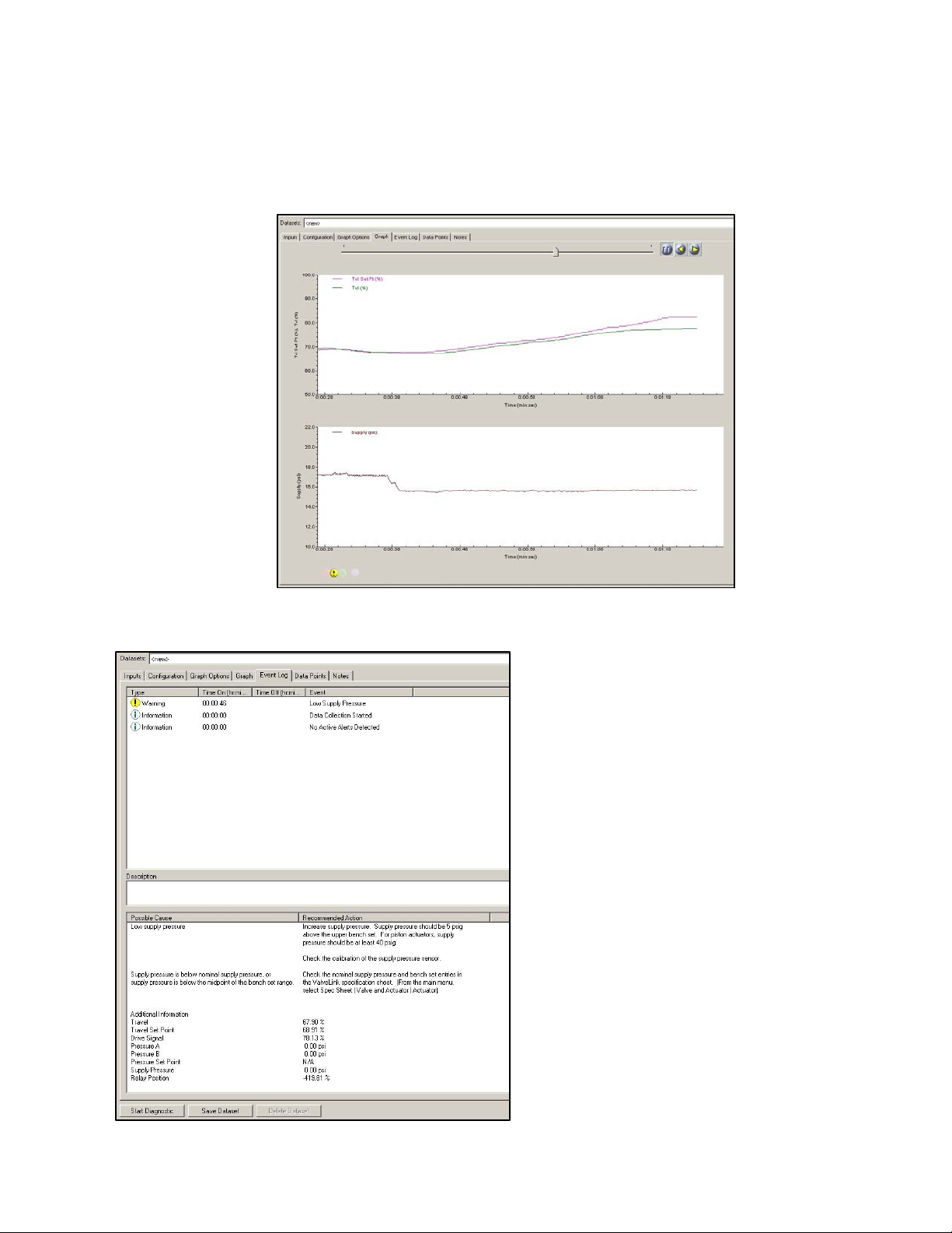
The Supply Pressure diagnostic test evaluates the instrument air supply pressure and volume. Diagnostic parameters
used are travel, travel set point, and supply pressure.
The root cause for
one out of every ten
control valves that
has been identified as
having a problem is
lack of air supply
volume or pressure.
This can cause a valve
to go unstable or not
allow it to reach full
travel.
What kind of issues can this
diagnostic detect?
a) Low supply pressure
b) High supply pressure
c) System pressure droop
d) Pressure sensor out of
calibration
e) Incorrect Benchset specified
23
Page 28

The Relay Adjustment diagnostic test evaluates the relay adjustment when the DVC6200/DVC6000 instrument is
used on double-acting piston actuators. The relay adjustment sets the pneumatic crossover pressure point of the
actuator. The diagnostic parameters used are travel set point, actuator pressure A, actuator pressure B, and supply
pressure.
In high vibration
applications, it is possible
for the instrument to be
shaken so violently that the
relay crossover wheel can
begin to move. This
changes the actuator
pneumatic crossover point,
meaning the valve is no
longer calibrated correctly.
This will look like the valve
has a setpoint offset. The
Relay Adjust diagnostic can
detect this situation.
What kind of issues can this diagnostic detect?
a) Relay Jammed
b) Relay crossover misadjusted
c) Crossover pressure low
d) Crossover pressure high
e) Port A Relay diaphragm failure
f) Port B Relay diaphragm failure
g) External leaks
h) Fail assist spring weakening or broken
24
Page 29

The Travel Deviation diagnostic test evaluates the reasons why a valve assembly is deviating from the set point. The
diagnostic parameters used are travel, travel set point, and actuator pressure.
Travel deviation occurs
most frequently in
applications with vibration
or temperature cycling.
Travel deviation looks like
a continuous offset, or an
offset that lasts for a
period of time. This
directly impacts the valve's
ability to accurately
control the process.
What kind of issues can this diagnostic
detect?
a) Travel calibration shift
b) I/P or relay fault
c) Supply pressure low
d) Blocked instrument supply air line
e) Valve stuck
f) Internal leaks
g) External leaks
25
Page 30

The I/P and Relay Integrity test evaluate the physical condition of the I/P and Relay components of the FIELDVUE
instrument. Diagnostic parameters are relay hall effect sensor position, travel, travel feedback position, and the drive
signal.
If you are having an I/P issue
from plugging of the primary
orifice, the valve may initially
be close to set point and
operations may not be aware
of an impending issue.
What kind of issues can this diagnostic
detect?
a) I/P beginning to plug
b) I/P O‐ring failure
c) Relay diaphragm failure
d) Supply pressure low
e) I/P calibration shift
f) Valve stuck low
g) Feedback linkage damaged
h) Actuator air line blocked or damaged
i) Actuator crossover adjustment wrong
26
Page 31

The Air Mass Flow test calculates the total air received and used by the DVC6200/DVC6000. It has the ability to
calculate the flow rate provided by the instrument air supply, and the output to the actuator. For double-acting
actuators, it can discriminate between positive and negative flow rates from each side of the piston. Diagnostic
parameters used are the relay hall effect sensor position, supply pressure, actuator pressure A, and actuator pressure
B for analysis.
A very common piston actuator
problem is a faulty piston O‐ring. This
appears as a valve that is no longer
calibrated and “wanders” around the
setpoint. In reality, the actuator has
lost its stiffness and the process
pressures are pushing the valve plug
around.
Piston O‐rings can fail over time when
continuously exposed to high
temperatures. This failure is one of the
hardest failure modes to
troubleshoot. PD can specifically
define this situation.
What kind of issues can this diagnostic
detect?
a) Kinked, cracked, or loose tubing
b) Piston actuator O‐ring failure
c) Actuator diaphragm leak
d) Incorrect regulator setting
e) Filter regulator plugging
27
Page 32

4. Advanced Diagnostics - Test Details (Out of Service Testing)
Advanced Diagnostic tests actively diagnose and troubleshoot instruments and control valves. Using Advanced
Diagnostics, you can run interactive tests that move the valve, poll for data, and display the data graphically. In most
cases this means that you are isolating the valve from the active process and are performing a dynamic stroke of the
valve assembly. The two tests included in the Advanced Diagnostics tier are the Dynamic Scan and Step Response
Test. The Dynamic Scan test consists of a Valve Signature, Dynamic Error Band, and Drive Signal data. It requires a
person with expertise in valve assembly construction and plot analysis to interpret the results of the test as no
“answer" is provided at the conclusion of these tests. There is no reason that you cannot become an expert also.
When looking at graphs, look for abnormalities; any change indicates something could be potentially wrong. Each
valve and actuator type will have its own distinct graph. Comparing the existing graph to the base line data is a good
place to start.
Valve Signature: Plots actuator PRESSURE versus valve TRAVEL. The test calculates friction, seat load, spring rate, and
a myriad of other variables. It is the only test that lets you see the condition of the valve seat. It is primarily used to
determine valve and actuator mechanical condition. Issues such as worn seat, worn/bent stem, insufficient air supply,
incorrect bench set, insufficient frictional forces, and stuck valve are examples of the issues that can be found using
this test.
Valve is saturated
all the way open.
Valve Seat
Example of a Valve Signature and analyzed data with a spring and diaphragm actuator
Analysis of valve
assembly
Valve spec sheet must be
filled out to perform this
detailed analysis.
28
Page 33

Dynamic Error Band: The Dynamic Error Band test plots valve TRAVEL versus INPUT setpoint. This test calculates
min/max/average dynamic error and dynamic linearity. The dynamic error band test shows a picture of the
performance of the entire valve assembly, including the instrumentation.
Drive Signal: Plots INPUT setpoint in percent of ranged travel versus the DRIVE SIGNAL of an instrument in percent of
maximum drive signal current. The drive signal gives you a measure of just how “hard" the instrument is working
while trying to position a valve. Standard drive signal ranges are from 55 - 85%. It is not uncommon, however, to see
the drive signal vary outside this range during sudden movement of the valve assembly. High drive signal
measurements mean that the instrument is working very hard to position the valve correctly. This can be an
indication of a sticking valve, an I/P that is starting to plug up with debris from the air supply system, or extreme
vibration that has caused the I/P calibration to shift.
Valve Signature: The Valve Signature can also be plotted in Pressure versus Time, Travel versus Time, and Travel %
versus Time test plots. Pressure/Time is another way of plotting the valve signature. It is most often used to look at fill
and exhaust of the actuator. At the upper part of the graph if there are no air leaks we expect to see the pressure
equal supply. Notice below there are two separate valves that are shown overlaid. As seen in the graph, one valve
assembly has a higher supply pressure. Notice the upper curve; it is indicative of air leaking past the O-rings of a 667
actuator.
Travel versus Time will give you a plot that is another way of looking at the dynamic error band. It can be useful for
comparison when zeroing in on a problem.
Pressure versus Time
29
Page 34

Step Response: This test plots valve TRAVEL versus the TIME it takes to move through the specific steps. It checks the
response of the entire valve assembly and gives you an indication of the effectiveness of the tuning of the
instrumentation and accessories. Small steps are useful to determine dynamic performance. Large steps are useful in
determining adequate supply pressure and accessory performance. Below is a plot of stroking time. This test was
done using ValveLink Mobile on a 475 and imported into ValveLink for analysis. It is always good to look at this graph
with supply pressure. Poor performance of valve assemblies can be caused by lack of supply volume.
Travel versus Time
Example of a Step Response Test
30
Page 35

5. Advanced Diagnostics Look and Feel
Q: What are Advanced Diagnostics (AD) used for now that Performance Diagnostics (PD) are available?
A: Advanced Diagnostics are a companion tool for Performance Diagnostics functionality. There are some things that
AD can identify that PD cannot - and vice versa. For example, a worn seat. Since the valve is not throttling in the seat,
PD cannot detect a seat that is worn. However, AD has the ability to give you a visual indication that the seat is
starting to wear. There is still tremendous value in performing a valve signature on a control valve assembly. Many
customers use this technology to ensure a valve assembly has been rebuilt and is performing correctly before
installation.
Q: Can my Performance Diagnostics tier instrument also perform Advanced Diagnostics tests?
A: Yes. PD includes AD functionality.
31
Page 36

VIII. Appendix C Value‐Add Features
Multiple tools have been developed in ValveLink software that provide you with more visibility to issues, as well as
help you be more efficient using the advanced features.
Triggered Profile: The DVC6000/DVC6200 has the capability to capture PD information when certain events occur.
These can be when the instrument is going into or out of cutoff, a travel deviation, or a combination of these two. For
a throttling control valve, you should trigger off of travel deviation. If the travel deviates from set point for the
percentage and time specified in detailed set up, the digital valve controller will store triggered data in the device for
the time specified. Thirty seconds is a good time period to start with. The device can hold approximately 20 minutes
of triggered data. Below is a typical setting for triggered profile.
32
Page 37

Scheduler: Scheduler is a tool that allows you to run various types of tests in a sequential manner at predefined
intervals without user intervention. The resulting data is available for later viewing and analysis. The Scheduler gives
you the capability to specify a time and date to automatically run a particular task on a particular device.
The Scheduler can perform these tasks:
One Button Performance Diagnostics Sweep
Partial Stroke Test (SIS or ODV instruments)
Upload Triggered Profile
Upload PST (Partial Stroke Test) data
Valve Friction (Performance Diagnostics)
Status Monitor
An unlimited number of tasks can be set up in the Scheduler on a daily, weekly, or monthly basis.
A history of all tasks completed is maintained in the History page of the Scheduler, indicating the problem found, the
reason for the problem, and a solution to resolve the problem.
33
Page 38

AMS Device Monitor Alert Log: If you are using ValveLink SNAP-ON, any alerts found by Scheduler will show up in the
AMS Device Manager Alert Monitor.
ValveLink Alert Log: In the Alert Log display area of the Network Scanning screen, ValveLink software lists alert
information including group and tag, alert type, and date and time when an alert was “turned on” and the “turn off”
time for all alerts. Alerts that are currently active (with no time off) are highlighted in the list. Use the scroll bar to view
all of the information in the Alert Log area.
The alert log shows historical events; it does not identify alerts that are currently active. The Alert Log is configured to
store a maximum number of alerts. After reaching the maximum number, ValveLink removes the oldest alerts from
the end of the log. It also allows you to print the Alert Log. It is NOT possible to edit this log.
34
Page 39

Status Monitor Trending: This is a new feature added to ValveLink version 12. Trending provides an easy visualization
of valve response to a control system output using an electronic strip chart. Trending is a diagnostic intended to
monitor standard instrument parameters during normal process operations. View live data received over the
multiplexer network, archived data, or data saved in a dataset. The last six minutes of a devices trend will be saved
when the Status Monitor is ended. The parameters that are recorded are:
Travel
Travel Setpoint
Pressure A (A-B for a double-acting piston)
Supply Pressure (AD & PD units only)
35
Page 40

Friction and Friction Trending:
ValveLink PD diagnostics allow for friction calculations while the valve is in service and running. It does not move the
valve, it only watches how a valve responds to a position change request from a control system. A single
friction/torque calculation is nice, but determining the friction/torque over time is also very important. Trending of
these parameters gives you a good idea of the health of the instrument and its pending issue. The dashed lines
represent an upper or lower friction or dead band limit. Once the friction/dead band goes beyond this limit, ValveLink
software can send an email notice to the appropriate personnel or post an alert to the Alert Monitor. Use the total
expected friction from the valve signature analysis for the upper range and then 25% of that value for the lower range.
If the valve has single TFE packing you can use 20% for this calculation. This feature can also be useful for finding build
up and sticking on rotary products. This measurement is done with process flowing thru the valve, you may also find
parts that are sticking or galling that didn't show up with testing that had the process isolated.
36
Page 41

Batch Runner: Batch Runner allows you to preconfigure a set of tests for a valve, or a set of valves. You can reuse the
batch whenever you need it, saving time and reducing the risk of errors. Many companies use this functionality by
creating startup batches for the valves they have in specific plant areas. For example, they will set up a batch for all
valves in the power house. They want all of valves in the power house to have the alert record cleared, clock reset,
configuration flag reset, and upload the configuration in case of changes. This is easily setup in a batch and the batch
can be run on all valves after startup.
Batch used in an integrated system is a very powerful tool. It allows you to mass edit large numbers of parameters for
multiple control valves. Do not mix in-service diagnostics with out of service diagnostics on a batch. The batch runner
will not take valves out of service or put them in-service, so some tests may not run.
Numerous task can be
performed using Batch Runner:
o Advanced Diagnostics
o Firmware Download
o Partial Stroke Tests
o Run Performance Tuner
o Reports
o Reset clock
o Reset Config Change flag
o Run Status Monitor
o Upload Configurations
o Auto Travel Calibration
37
Page 42
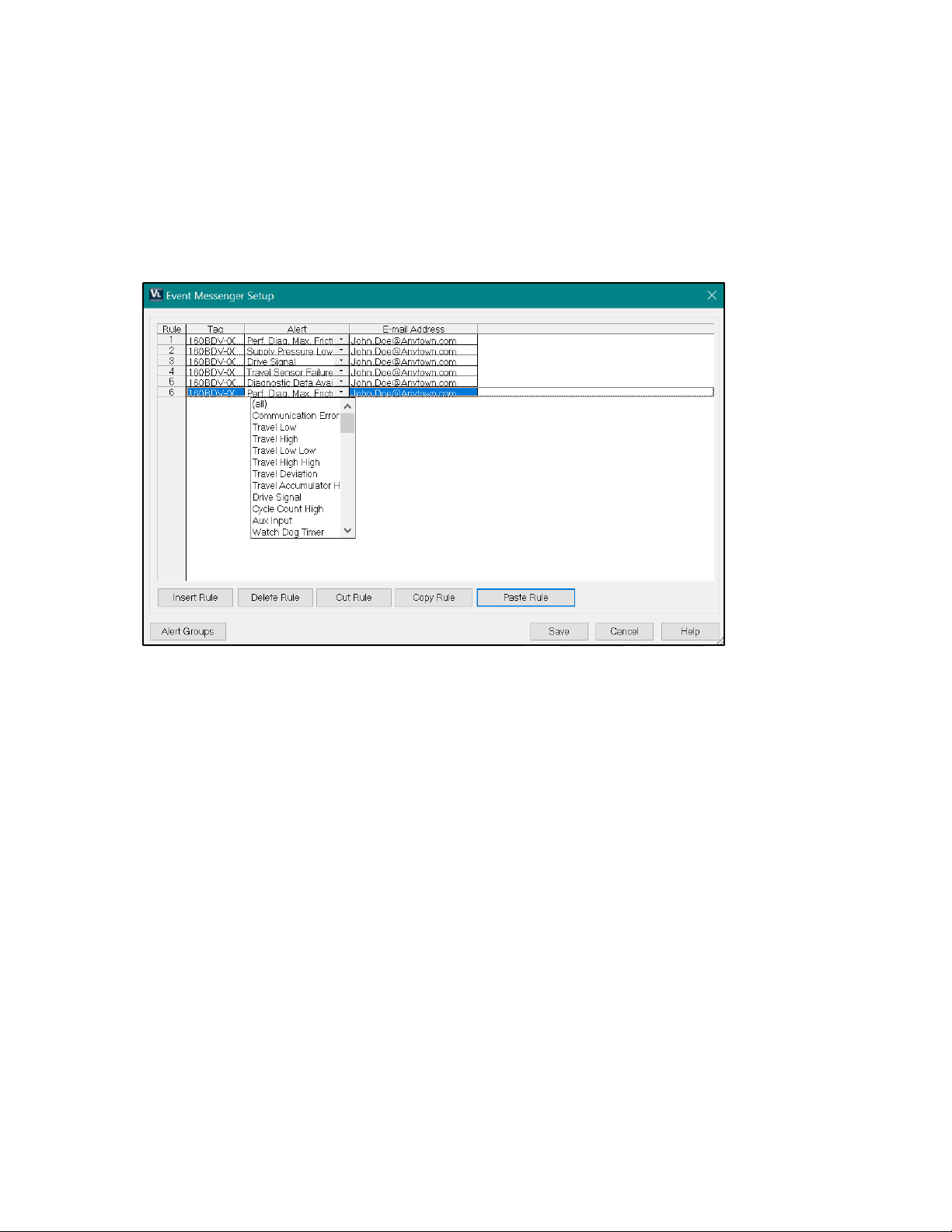
Event Messenger: Event Messenger provides you an easy way notify appropriate personnel of issues. This tool makes
use of the email system. Email can be directed towards a text message box, pager, or standard email inbox.
You can predefine what types of alerts for each specific valve or groups of valves go to which person. This is a very
powerful tool in an integrated environment where the system extends across multiple areas of the plant. Different
maintenance personnel can be notified as appropriate in this situation.
38
Page 43

39
Page 44

Neither Emerson, Emerson Automation Solutions, nor any of their affiliated entities assumes responsibility for the selection, use or maintenance of
any product. Responsibility for proper selection, use, and maintenance of any product remains solely with the purchaser and end user.
Fisher, FIELDVUE, SNAP-ON, ValveLink, PlantWeb, Baumann, DeltaV, and Ovation are marks owned by one of the companies in the Emerson Automation
Solutions business unit of Emerson Electric Co. Emerson Automation Solutions, Emerson, and the Emerson logo are trademarks and service marks of Emerson
Electric Co. All other marks are the property of their respective owners. HART is a registered trademark of FieldComm Group. FOUNDATION Fieldbus is a
trademark of FieldComm Group. All other marks are the property of their respective owners.
The contents of this publication are presented for informational purposes only, and while every effort has been made to ensure their accuracy, they are not to
be construed as warranties or guarantees, express or implied, regarding the products or services described herein or their use or applicability. All sales are
governed by our terms and conditions, which are available upon request. We reserve the right to modify or improve the designs or specifications of such
products at any time without notice.
Emerson Automation Solutions
Marshalltown, Iowa 50158 USA
Sorocaba, 18087 Brazil
Cernay, 68700 France
Dubai, United Arab Emirates
Singapore 128461 Singapore
www.Fisher.com
40
2007, 2020 Fisher Controls International LLC. All rights reserved.
 Loading...