

Page 1

sto
abcock
ControlWave
Redundancy
Setup Guide
Bri
D5123 – December, 2005
l B
Page 2

The information in this document is subject to change without notice. Every effort has been
made to supply complete and accurate information. However, Bristol Babcock assumes no
responsibility for any errors that may appear in this document.
Bristol Babcock does not guarantee the accuracy, sufficiency or suitability of the software
delivered herewith. The Customer shall inspect and test such software and other materials to
his/her satisfaction before using them with important data.
There are no warranties, expressed or implied, including those of merchantability and fitness for
a particular purpose, concerning the software and other materials delivered herewith.
Bristol is a registered trademark of Bristol Babcock. Other trademarks or copyrighted products
mentioned in this document are for information only, and belong to their respective companies,
or trademark holders.
Copyright (c) 2005, Bristol Babcock, 1100 Buckingham St., Watertown, CT 06795. No part of
this manual may be reproduced in any form without the express written permission of Bristol
Babcock.
Page 3

IMPORTANT! READ INSTRUCTIONS BEFORE STARTING!
Be sure that these instructions are carefully read and understood before any
operation is attempted. Improper use of this device in some applications may result
in damage or injury. The user is urged to keep this book filed in a convenient
location for future reference.
These instructions may not cover all details or variations in equipment or cover
every possible situation to be met in connection with installation, operation or
maintenance. Should problems arise that are not covered sufficiently in the text, the
purchaser is advised to contact Bristol Babcock for further information.
EQUIPMENT APPLICATION WARNING
The customer should note that a failure of this instrument or system, for
whatever reason, may leave an operating process without protection. Depending
upon the application, this could result in possible damage to property or injury to
persons. It is suggested that the purchaser review the need for additional backup
equipment or provide alternate means of protection such as alarm devices, output
limiting, fail-safe valves, relief valves, emergency shutoffs, emergency switches, etc.
If additional information is required, the purchaser is advised to contact Bristol Babcock.
RETURNED EQUIPMENT WARNING
When returning any equipment to Bristol Babcock for repairs or evaluation,
please note the following: The party sending such materials is responsible to ensure
that the materials returned to Bristol Babcock are clean to safe levels, as such levels
are defined and/or determined by applicable federal, state and/or local law
regulations or codes. Such party agrees to indemnify Bristol Babcock and save
Bristol Babcock harmless from any liability or damage which Bristol Babcock may
incur or suffer due to such party's failure to so act.
ELECTRICAL GROUNDING
Metal enclosures and exposed metal parts of electrical instruments must be
grounded in accordance with OSHA rules and regulations pertaining to "Design
Safety Standards for Electrical Systems," 29 CFR, Part 1910, Subpart S, dated: April
16, 1981 (OSHA rulings are in agreement with the National Electrical Code).
The grounding requirement is also applicable to mechanical or pneumatic
instruments that include electrically-operated devices such as lights, switches, relays,
alarms, or chart drives.
Page 4

Thank you for choosing ControlWave!
We hope you will find ControlWave to be the best solution for your process automation needs.
From the start, Bristol Babcock designed this unit to merge the simplicity and modularity of a
programmable logic controller, with the full communication and programming capabilities of a
remote process controller. The result - the ControlWave-series of Process Automation
Controllers, are true PLC/RTU hybrids, incorporating the best features of both types of devices.
ControlWave features a low-power, modular design, which supports all five IEC 61131-3
programming languages: ladder logic (LD), sequential flow chart (SFC), function block diagram
(FBD), structured text (ST), and instruction list (IL). A full suite of PC-based configuration
wizards and programming tools is provided, as well as a rich library of Bristol Babcock function
blocks that may be used for various process control applications.
Before You Begin
This guide is intended to help you get redundancy 'up-and-running' with a minimal amount of
effort. It does NOT, however, tell you everything you need to know about setting up and
configuring ControlWave hardware and software. We have included references throughout this
book to other places in the documentation set, where you can get more details on a particular
subject.
Throughout your configuration activities, please be aware of the following items:
Shock Hazard! Always follow accepted safety guidelines. As with all electronic devices,
improper installation, grounding, or usage can cause an electrical shock. If you have any doubts
about how to install, ground, and use this product safely, please consult a qualified electrician.
Electrostatic Discharge (ESD) - Sensitive electronic devices such as this can be damaged by
electrostatic discharge. Please follow accepted ESD guidelines.
If You Need Help…
If you're having problems setting up and configuring your ControlWave, please call our
ControlWave Application Support team at (860) 945-2394 or (860) 945-2286 for assistance.
Help is available Monday through Friday 8:00 AM to 4:30 PM Eastern Time, excluding
holidays, and scheduled factory shutdowns.
4
Page 5

Table of Contents
The Concept of Redundancy........................................................................................................... 9
Redundancy Options Available ..............................................................................................10
Control Redundancy - CPU and Power Supply.............................................................. 10
Local I/O Redundancy.................................................................................................... 13
I/O Expansion Rack Redundancy................................................................................... 14
Setting up Redundancy Hardware ................................................................................................ 17
Major Types of ControlWave Redundancy Hardware ........................................................... 17
ControlWave Redundant Controller............................................................................... 17
Setting Up the ControlWave Redundant Controller......................................... 19
ControlWave Process Automation Controller................................................................ 24
ControlWave I/O Expansion Rack ................................................................................. 25
ControlWave I/O Switcher............................................................................................. 26
Overview of I/O Switcher Hardware Configuration ........................................ 27
Establishing Communications ...................................................................................................... 29
Establishing Communications Using LocalView .................................................................. 29
Establishing Communications Using NetView (ControlWave Already In a Network)......... 31
Setting Flash Parameters............................................................................................................... 32
Before you Begin ................................................................................................................... 33
Signing on to the ControlWave.............................................................................................. 33
Setting Up an Ethernet Port.................................................................................................... 33
Recommended Ranges for IP Addresses ............................................................................... 35
Setting Application Parameters for Redundancy................................................................... 36
Setting other Flash Parameters............................................................................................... 36
Saving the Flash Parameters to the Unit................................................................................ 37
Activating the newly saved parameters.................................................................................. 38
Saving the same parameters to the other unit:........................................................................ 38
Ethernet Connection Redundancy................................................................................................. 39
Testing the Redundant Setup (CPU and Power Supply) .............................................................. 40
Before Testing Redundancy................................................................................................... 40
Using the Sample Redundant Project or Creating Your Own Redundant Project................. 40
Testing the Redundant Setup.................................................................................................. 41
Notes on Redundant Operation..................................................................................................... 46
How do I force a fail-over to the Standby unit via program control?.................................... 46
Forcing I/O Expansion Rack Fail-over via Program Control ................................................ 49
How do I manually force a fail-over to the Standby unit?..................................................... 52
Manually failing over from "A" to "B".................................................................................. 52
Manually failing over from "B" to "A".................................................................................. 52
Return the A/B Enable Key Switch to Automatic Mode....................................................... 53
Specifying a New Primary Unit.............................................................................................. 53
Page 6

Codes Which Appear on the Standby Unit Display................................................................ 53
Redundancy Status Variables ....................................................................................................... 54
Troubleshooting Redundancy Problems....................................................................................... 59
6
Page 7

IMPORTANT:
This document is intended to describe the main steps necessary to configuring
ControlWave redundancy. It does NOT include everything you need to know about
configuring a ControlWave controller.
The following is assumed:
• The OpenBSI Network Edition and ControlWave Designer software kits have been
installed on your PC. If this is not the case, please see Chapter 2 of the Open BSI
Utilities Manual (document# D5081) for details on the installation procedure.
• Some familiarity with ControlWave software configuration.
7
Page 8

8
Page 9

The Concept of Redundancy
The Concept of Redundancy
Redundancy is a mechanism employed to prevent the loss of control over a process, and to
minimize the loss of data, which can occur, if any single part of a control system should fail.
Redundancy is recommended for plants or processes where a loss of control could result in
damage or injury.
All methods of ControlWave redundancy involve having a duplicate standby unit that is able to
take over in the event there is a failure in the primary unit. The process of transferring control
from the primary to the backup is referred to as fail-over. A fail-over condition typically falls
into one of two categories:
Hardware failures - These could occur from a variety of causes:
• loose cable
• improper configuration, e.g. board not seated properly
• power supply failure (no power for CPU)
• individual board or component breakdown
Software failures - Possible causes include:
• application program running in the CPU 'crashes', as indicated by an 'FF' code on the display
• all tasks are suspended for more than a user-configurable number of milliseconds
• a task watchdog occurs (this option can be user enabled/disabled)
• user-created logic for detection of a particular failure (e.g. local I/O) is activated, triggering a
switchover via a REDUN_SWITCH function block.
• user-created logic for detection of a particular failure in an I/O Expansion Rack, triggering a
switchover via the ERSTAT_x_FAILOVER_O system variable.
When redundancy is used, these sorts of failures trigger a watchdog relay, and cause a fail-over
from the on-line unit that failed to a standby backup unit. The standby unit has been configured
to be an exact duplicate of the on-line unit (except for the A/B switch setting and IP addresses)
so it can now assume full control over the process previously controlled by the failed unit, and
becomes the new on-line unit.
The redundant units that make up the primary and standby pair are referred to as the “A” unit,
and the “B” unit.
ControlWave redundancy only handles a single point of failure i.e. either the “A” set of
CPU/power supply/ or I/O can have a failure, or the “B” set of CPU / power supply or I/O can
have a failure. A failure of the “A” CPU, and the “B” power supply, however, would disable the
entire control system.
9
Page 10

The Concept of Redundancy
Redundancy Options Available
IMPORTANT
Throughout this manual, we will refer to the redundant units that make up the primary and
standby pair as the “A” unit, and the “B” unit. This term is used whether the units in
question refer to the “A” and “B” units in a ControlWave Redundant Controller, the “A”
and “B” ControlWave Process Automation Controllers, or “A” and “B” ControlWave I/O
Expansion Racks.
The ControlWave family of products offers three distinct types of redundancy. The choice of
which type(s) of redundancy you need is dictated by the needs of your particular application.
Your system may even include a mixture of the different types of redundancy.
Control Redundancy - CPU and Power Supply
Control Redundancy provides protection in the event a single failure occurs in either the
Central Processing Unit (CPU), or the Power Supply (PSSM) of a ControlWave controller.
ControlWave
Redundant
Controller
ControlWave I/O
Expansion Rack
(shared by both
Unit “A” and Unit “B”)
Unit “A”
CPU &
PSSM
W
I
RRTT
1
234
Unit “B”
CPU &
PSSM
W
I
RRTT
1
234
CCRS
10
Page 11

The Concept of Redundancy
Control redundancy is accomplished using the ControlWave Redundant Controller plus one or
more ControlWave I/O Expansion Racks. I/O Expansion Racks are required because the
ControlWave Redundant Controller does NOT support any local I/O boards.
Alternatively, Control redundancy can be accomplished using two separate ControlWave Process
Automation Controllers in conjunction with a ControlWave I/O Switcher. Because this particular
configuration also allows for Local I/O Redundancy, we will show a picture of it later, in the
‘Local I/O Redundancy’ section.
In either case, whenever the on-line ControlWave CPU receives a download of a new
ControlWave project file (boot project), that project is immediately transmitted to the Standby
ControlWave unit, and stored. This is known as a side-load, and typically occurs through an
Ethernet connection between the “A” and “B” units, which may either be specifically dedicated
for that purpose, or may also be used for Ethernet communications with other devices on the
network. Once the side-load occurs, the boot project is loaded into memory in the Standby but
kept in the 'Stopped' state.
On-line unit receives
download of a new
ControlWave project
file (boot project)
Standby receives a
side-load of the new
On-line CPU
Unit A
boot project from the
On-line unit
Standby CPU
Unit B
The on-line ControlWave CPU is the only unit executing the project, communicating with I/O
boards and controlling the plant or process. The Standby CPU sits idle except for receiving
updates from the on-line unit.
The updates from the on-line unit to the standby unit occur at the end of each task execution
cycle, unless:
• there have been no changes to process I/O output variables -and-
• the minimum update time1 has not expired
1
The minimum update time is a configured value that may be used to limit the amount of traffic b etween the on-line
unit and the standby unit. Every time an update occurs the mini mu m u pd ate ti mer is res t art ed. Unless process I/O
output changes occur, any changes occurring during the time prior to expiration of the configured update timer will
not trigger an update to the standby unit. Instead, they will be held until expiration of the timer, and the end of a
task execution cycle. The timer value is set via the _RDN_MIN_UPD system variable.
11
Page 12

The Concept of Redundancy
Updates between the on-line unit, and the standby unit, may consist of multiple update messages,
followed by a ‘commit’ message. Until the commit message is received, the update messages are
not applied to the standby. This ensures that if the on-line unit fails before it sends the ‘commit’
message, that a partial update, e.g. incomplete data, is not used. Instead, the standby will discard
the incomplete update data, and start up using the last complete update that ended with a commit
message.
In general, data is only transferred from the on-line unit to the standby unit if it has changed.
Among the types of data transferred are:
• Any changed process I/O output variables
• All variables marked as RETAIN in the user's project
• Any data in the static memory area (begins at address 3.100000)
• Certain function block parameters that are retained
• Changes to certain port configuration information such as on-line baud rate changes, etc.
• Changes to user account definitions (usernames, passwords)
• Any newly generated alarms plus any changed alarm states from alarm function blocks
• Historical data (audit records, archive files)
On-line unit is curren t l y
running the project to
control the process
or plant, receiving data
via I/O boards, etc.
On-line CPU
Unit A
At the end of
each execution
cycle, changes
are copied to
the Standby, to
keep it up-to-date
Standby sits idle, except
for receiving updates from
the on-line unit.
Standby CPU
Unit B
If a failure occurs at the on-line unit, a watchdog relay is triggered, and control is switched to the
Standby CPU. The Standby CPU now becomes the new on-line unit.
12
Page 13

The Concept of Redundancy
p
o
p
izzle
s
NEW On-line CPU
Unit B
(formerly the Standby unit)
FAILED CPU
Unit A
Unit "A" suffers a component failure. Control is automatically
transferred to the "B" unit. The "B" unit becomes the NEW
on-line unit, and starts up its boot project.
The "B" unit is up-to-date to the point of the last COMPLETE
update received from "A" unit. (Typically, that would have
been the last execution cycle of the "A" unit, prior to its failure.)
Local I/O Redundancy
Local I/O redundancy provides protection in the event a single failure occurs in either the Central
Processing Unit (CPU), Power Supply, or I/O boards in one of two ControlWave Process
Automation Controllers serving together as a redundant pair.
This redundant configuration would require two (2) ControlWave Process Automation
Controllers, plus a ControlWave I/O Switcher.
ControlWave Process
Automation Controller
“Unit B”
ControlWave
I/O Switcher
ControlWave Process
Automation Controller
“Unit A”
Connections to
field inputs/outputs
13
Page 14

The Concept of Redundancy
With respect to failures of the CPU and power supply, everything would be handled exactly as
described previously in the ‘Control Redundancy - CPU and Power Supply’ section.
Detection of I/O failures, however, is handled differently. The ControlWave series controllers
cannot automatically detect an I/O failure based on data alone. The user must devise logic within
their ControlWave project to determine when a fail-over should occur, and then use a
REDUN_SWITCH function block, in their ControlWave project to trigger the actual fail-over.
When the fail-over occurs, I/O is automatically switched from the on-line unit to the backup
standby unit, which becomes the new on-line unit.
The logic for whether or not a given failure is sufficient reason to force a fail-over to the Standby
unit is based entirely on the user’s own criteria for what constitutes a serious failure. When
activated, this logic serves as a trigger to the REDUN_SWITCH function block, which forces the
fail-over.
Among the items which users might want to consider when making a determination of a local
I/O fail-over could be:
• Comparisons of data from the I/O board in question, with data collected independently from
some separate source.
• Board status codes that can indicate whether or not a board is present, or for analog boards,
whether a conversion operation failed. See the ‘I/O Mapping’ section of the ControlWave
Designer Programmer’s Handbook (document# D5125) for more information on these
codes.
• User-defined timeouts or out-of-range calculations.
• Current status of I/O boards in the standby unit, i.e. is the standby able to take over. This
information is accessible via system variables.
I/O Expansion Rack Redundancy
I/O Expansion Rack redundancy provides protection in the event a single failure occurs in either
of two ControlWave I/O Expansion Racks serving together as a redundant pair.
This redundant configuration would require two (2) ControlWave I/O Expansion Racks, a
ControlWave I/O Switcher, and a Host ControlWave unit, since the I/O Expansion Racks cannot
execute a ControlWave project, they just handle I/O operations.
Typically, the host ControlWave would be a ControlWave Redundant Controller.
14
Page 15

The Concept of Redundancy
s
Unit “A”
CPU &
PSSM
ControlWave Redundant
Controller provides Control
Redundancy , and also serves
as ‘Host’ to pair of redundant
I/O Expansion Racks.
This type of configuration allows Control Redundancy, via the dual CPUs and power supplies of
the ControlWave Redundant Controller, plus I/O redundancy via the dual ControlWave I/O
Expansion Racks, and ControlWave I/O Switcher.
Alternatively, the host could be a single ControlWave Process Automation Controller, in which
case this segment of the network would have NO CPU or power supply redundancy, but would
have I/O Expansion Rack Redundancy.
Unit “B”
CPU &
PSSM
W
W
I
I
RRTT
RRTT
1
1
234
234
CCRS
ControlWave I/O
Expansion Rack
“Unit B”
ControlWave
I/O Switcher
Connections to
field inputs/outputs
ControlWave I/O
Expansion Rack
“Unit A”
ControlWave I/O
ControlWave Process Automation
Controller serves as ‘Host’ to pair
of redundant I/O Expansion Racks.
There is NO CPU or power supply
redundancy in this configuration.
Expansion Rack
“Unit B”
ControlWave
I/O Switcher
Connections to
field inputs/output
ControlWave I/O
Expansion Rack
“Unit A”
Another possible configuration would be to use a pair of ControlWave Process Automation
Controllers, in conjunction with their own dedicated ControlWave I/O Switcher, as the host. In
general, this type of configuration would only be used in situations where a single ControlWave
Process Automation Controller does not have sufficient local I/O capacity for a given
application, and so additional I/O is needed, via I/O Expansion Racks. This system incorporates
Control Redundancy, plus Local I/O Redundancy, and I/O Expansion Rack Redundancy. In this
particular set up, because there are two separate ControlWave I/O Switchers, the “A” and “B”
units of each one are considered independent of each other, therefore, the control system could
still function even if, for example, the “A” I/O Expansion Rack failed, and the “B” Process
Automation Controller also failed, because the “B” I/O Expansion Rack could be used with the
“A” Process Automation Controller.
15
Page 16

The Concept of Redundancy
s
No matter which of these configurations you use, detection and handling of I/O failures in the
I/O Expansion Rack is handled by user-defined logic, in the host controller.
The I/O Expansion Racks cannot automatically detect an I/O failure based on data alone. The
user must devise logic within their ControlWave project to determine when a fail-over should
occur. See the ‘Local I/O Redundancy’ section for a list of possible I/O failure criteria.
If the user determines that a fail-over is necessary, it must be triggered by a user write to the failover variable on the ER_STAT board. (NOTE: The ER_STAT board is not an actual physical
I/O board, but a virtual board that maintains data related to the I/O Expansion Rack.) When the
fail-over occurs, I/O is automatically switched from the on-line rack to the backup standby rack,
which becomes the new on-line unit.
The logic for whether or not a given failure is sufficient reason to force a fail-over to the Standby
unit is based entirely on the user’s own criteria for what constitutes a serious failure. When
activated, this logic serves as a trigger to the ER_STAT fail-over variable, which forces the failover.
NOTE: Non-I/O-related hardware failures which trigger the watchdog relay, for example, a
power failure at the on-line I/O Expansion Rack, will also force a fail-over to the standby unit.
ControlWave Process
Automation Controller
“Unit B”
ControlWave
I/O Switcher
Connections to
field inputs/outputs
for LOCAL I/O ONLY
ControlWave Process
Automation Controller
“Unit A”
ControlWave I/O
Expansion Rack
“Unit B”
ControlWave
I/O Switcher
Connections to
field inputs/output
ControlWave I/O
Expansion Rack
“Unit A”
16
Page 17

Setting up Redundancy Hardware
Setting up Redundancy Hardware
Major Types of ControlWave Redundancy Hardware
There are four (4) major pieces of ControlWave hardware that are useful in various redundant
ControlWave configurations. We will list each type here, and then provide a brief overview how
it works, and how it is set up, or provide references to where setup information is available.
Which types of hardware you use will depend upon which form(s) of redundancy you are
incorporating into your system: Control Redundancy, Local I/O Redundancy, or I/O Expansion
Rack Redundancy. The four types of redundancy hardware are:
• ControlWave Redundant Controller
• ControlWave Process Automation Controller
• ControlWave I/O Expansion Rack
• ControlWave I/O Switcher
ControlWave Redundant Controller
If you have a system which uses Control Redundancy ONLY, you will need a ControlWave
Redundant Controller (See ‘Control Redundancy - CPU and Power Supply’, earlier in this
manual.) The ControlWave Redundant Controller can also be used as the host controller, in a
system using I/O Expansion Rack Redundancy (See ‘I/O Expansion Rack Redundancy’, earlier
in this manual.)
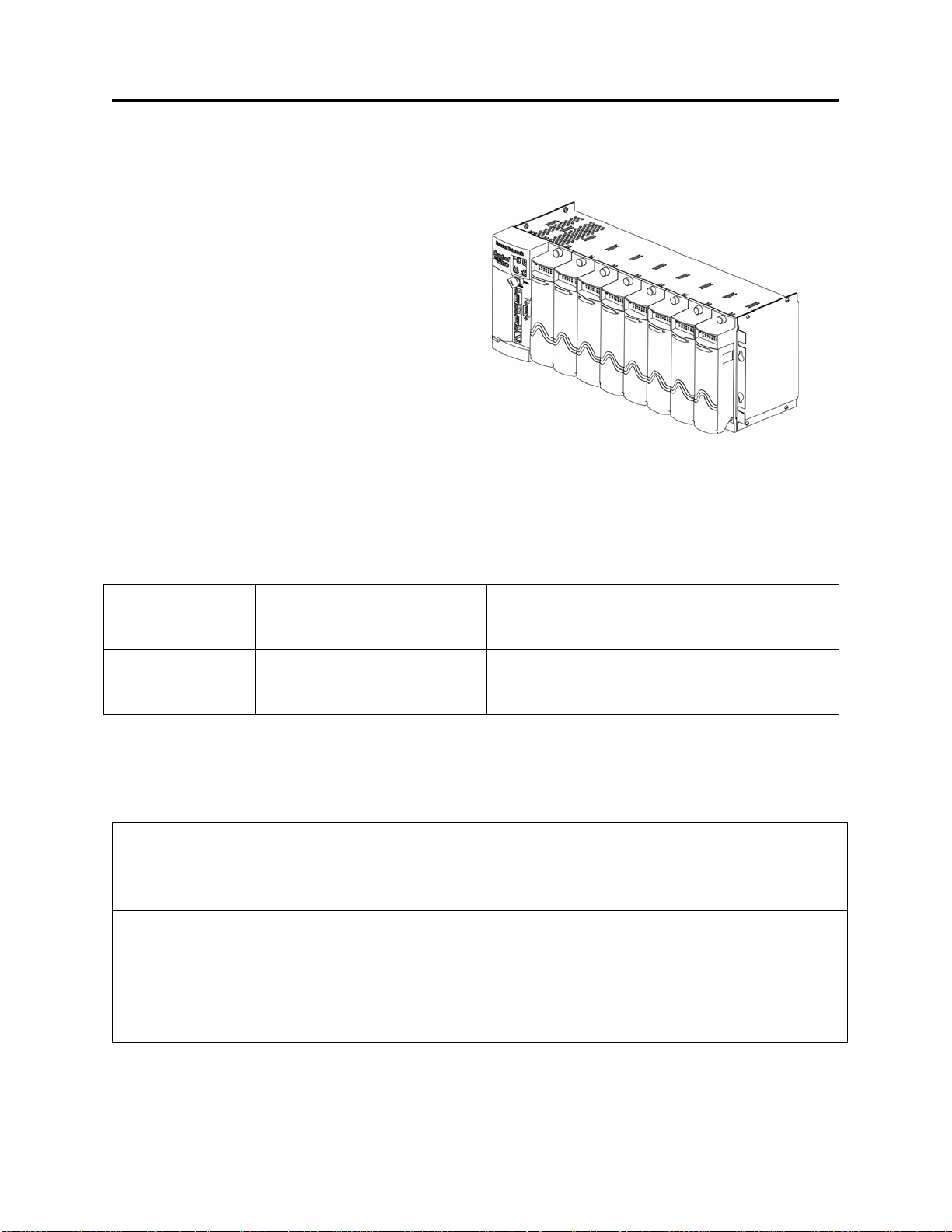
The ControlWave Redundant Controller
consists of a single chassis holding a pair
of ControlWave central processing units
(CPUs) and power supplies, linked
together by a CPU and Communications
Redundancy Switch (CCRS) module.
The ControlWave Redundant Controller
has no local I/O; I/O resides in one or
more ControlWave I/O Expansion
Racks, and is shared between the two
CPUs. Only the on-line CPU
communicates with the I/O).
CPU and
power supply
“A”
CPU and
power supply
“B”
CCRS
17
Page 18

Setting up Redundancy Hardware
a
Redundant pair of ControlWave CPUs
They share the SAME node name in NetView
but each has a DIFFERENT IP address
ON-LINE
Unit "A"
IP address a.b.c.d
On-line unit is currently
in control of the process
or plant, communicating,
receiving data via I/O
boards, etc.
CCRS
The switch
allows the
automatic
fail-over from
one unit to
the other. It
also can be
used to 'force'
a manual
f
il-over.
STANDBY
Unit "B"
IP Address e.f.g.h
Standby sits idle
as a backup. It
waits to take
over should the
on-line unit fail.
18
Page 19

Setting up Redundancy Hardware
Setting Up the ControlWave Redundant Controller
This configuration involves unpacking the ControlWaveRED hardware, making proper ground
connections, connecting a communication cable to the PC workstation and setting switches. The
basic steps are outlined, below. For detailed information on a particular step, please consult the
referenced hardware manual.
1. Remove the unit from its carton and install it at its assigned work site. (see Section 2.3.1 of
CI-ControlWaveRED).
2. Install a ground wire between the Chassis Ground Lug and a known good Earth Ground (see
Section 2.3.1.1 of CI-ControlWaveRED).
3. Units are shipped from the factory with CPU switches set for redundant operation, and the
backup battery disabled. If the switch settings have been changed, please set them correctly
according to the following instructions.
Setting CPU Module DIP Switches on each CPU:
For Switch Bank SW1:
Switch
Number
SW1-1 ON This enables the Watchdog circuitry, which is required.
SW1-2 ON This unlocks soft switches, which is required.
SW1-3 ON This forces soft switches to be used, which is required.
SW1-4 See
SW1-5 ON This must be set to ON so that RETAIN memory can be
SW1-6 OFF This enables redundant operation, which is required.
SW1-7 See
SW1-8 ON This enables the boot project, which is required.
Must be
set to:
Notes
notes
Notes:
For firmware versions earlier than 4.2: Had to be set ON to
disable updump. For Version 4.2 or newer: Can be set either
ON (to disable updump), or OFF, to enable updump. Neither
switch position has an effect on the normal operation of the
unit, since updump mode is not activated unless the user
operates the RUN / REMOTE / LOCAL key switch, in a
particular sequence, to trigger the updump.
used.(Required)
This switch must be set either ON or OFF based on whether this
is the "A" CPU (which resides in Chassis slot 2) or the "B" CPU
(which resides in Chassis slot 4):
• SW1-7 must be ON if this is the "A" CPU (in Chassis slot 2)
• SW1-7 must be OFF if this is the "B" CPU (in Chassis slot
4)
19
Page 20

Setting up Redundancy Hardware
For Switch Bank SW3:
For Switch Bank SW3, all switches should be left in their default position of 'OFF' except for
SW3-4 which must be set to 'ON' to enable the backup battery. This is because units are
shipped from the factory with the backup battery disabled, to reduce the drain on the battery.
To enable the backup battery remove the “A” CPU Module from chassis slot 2, and set
switch SW3-4 to ON, then re-install it in chassis slot 2. Next, remove the “B” CPU Module
from chassis slot 4, and set switch SW3-4 to ON. Then re-install it in chassis slot 4. (see
Section 2.3.3. of CI- ControlWaveRED).
Reset
Switch
Comm.
Port 1 (J2)
Lithium
Battery
3.6V
950mA-hr
½ AA Cell
Comm.
Port 2 (J3)
Ethernet
Port 1 (J4)
Enlarged detail
of CPU switch
banks
(CAPITALIZED entry
indicates ON position)
Bootproject ENABLE / disable
Redundancy DISABLE / enable
static memory RETAIN / initialize
Updump DISABLE / enable
Soft switches USE / ignore
Soft switches write UNLOCK / lock
Watchdog circuit ENABLE/disable
UNIT A / unit B
Port 80
Display
Run/
Remote/
Local
Key Switch
SW1
SW1
SW3
SW3
Leave all SW3
CPU switches
in default 'OFF'
position, except
for #4.
ENABLE/disable battery backup
recovery mode ENABLE/disable
Unused
Unused
(CAPITALIZED entry
indicates ON position)
Most SW1 switches should be 'ON',
but SW1-6 MUST be ‘OFF’ to enable
redundancy, and SW1-7 must be set
'ON' if this is the "A" CPU, or
'OFF' if this is the "B" CPU.
20
Page 21

Setting up Redundancy Hardware
s
4. Install Watchdog Relay/MOSFET Switch wiring to each PSSM Module (see Section
2.3.4.1.3 of CI-ControlWaveRED).
+12Vdc Bulk Supply #1 Pos. Term.
+12Vdc Bulk Supply #1 Neg. Term.
Chassis Ground
+24Vdc Bulk Supply #1 Pos. Term.
+24Vdc Bulk Supply #1 Neg. Term.
Chassis Ground
5. Connect Bulk DC Power to each of the ControlWaveRED’s PSSM Modules, but don't apply
power at this time (see Section 2.3.4.1 through Section 2.3.4.1.2 of CI-ControlWaveRED).
6. Install the Bezels so that each one covers its associated PSSM and CPU Modules (see
Section 2.3.6 of CI-ControlWaveRED).
7. Connect the special serial communications cable between the four serial communications
ports on CPU Module A and Connector J5 on the front (left) of the CCRS Module. Then
connect the other special serial communications cable between the four serial communication
ports on CPU Module B and connector J6 on the front (right) of the CCRS Module.
Typical Configuration
+VIN
1
+VINF
Shared +12Vdc Power Supply
-VIN
-VINF
CHASSIS
5
+VIN
1
+VINF
Shared +24Vdc Power Supply
-VIN
-VINF
CHASSIS
5
21
Page 22

Setting up Redundancy Hardware
A / B Enabled switch
Run / Remote/ Local
switch
CPU & Power supplyACPU & Power Supply
B
&
= Serial Comm. Port Designation
CPU & Communications
Redundancy Switch (CCRS) Module
12
COM1 COM2
1
6
J1 J2
9
5
COM3 COM4
49
50
J3 J4
J5 J6
1
J7
= Ethernet Comm. Port Designation
8. Connect COMM Port 2 of the CPU & Communications Redundant Switch Module (CCRS)
to one of the communication ports on your PC or laptop. (For more information on
communication ports see Section 2.3.3.2 of CI-ControlWaveRED).
2
• Plug one end of an RS-232 null modem cable
into one of your PC communication ports.
• Plug the other end of the RS-232 null modem cable into Serial Communication Port 2
(COM2) of the ControlWaveRED's CCRS Module.
10. Set the CCRS Module's A/B Enabled key switch to the "A" position.3
11. Set the RUN/REMOTE/LOCAL switch on both CPU A and CPU B to 'LOCAL'.
2
For a wiring diagram of an RS-232 null modem cable, see Figure 2-8 in the CI-ControlWave manual.
3
We have chosen 'A' for purposes of this example, however, you could have chosen 'B', and substituted 'B' in
subsequent steps which mentioned 'A'.
22
Page 23

Setting up Redundancy Hardware
12.Connect an Ethernet cable between one of the Ethernet Ports on CPU Module A and an
Ethernet Hub. Connect another Ethernet cable between the same Ethernet hub and the
Ethernet Port on CPU Module B with the same designation, i.e. Ethernet Port 1 (E1),
Ethernet Port 2 (E2) or Ethernet Port 3 (E3). Alternatively, you can omit the hub, and
connect a Point-to-Point 10Base-T Ethernet cable directly between the two ports.4
13. Apply power to the ControlWaveRED by setting the power s witch on the “A” unit to the '1'
position. (The power switch is located behind the bezel door). When the power up sequence
is completed, the status display should either be blank, or show “00”. “00” appears if there is
no project loaded; if it is blank, it means a project is already loaded and running. For a full
description of possible running status codes, see Table 2-9 in the CI-ControlWaveRED
manual.5
At this point, you can proceed to connect devices to any unused serial and Ethernet ports(s) as
required by your particular application.
4
For more information on the Point-to-Point 10Base-T Ethernet cable, see Figure 2-13 in the CI-
ControlWaveRED manual.
5
Table 2-9 in CI-ControlWaveRED shows the normal status codes you are most likely to see. Table 3-3 of the same
manual covers Power On Self-Test (POST) status codes, most of which are not seen unless there is an error prior to
completion of the power up. One POST code you may encounter is "86" which indica tes that the unit has been set
for recovery mode (switch SW3-3 is ON) to allow a field upgrade of system firmware.
23
Page 24
Setting up Redundancy Hardware
ControlWave Process Automation Controller
The standard ControlWave Process Automation
Controller, when used in pairs of two (2), with
an I/O Switcher, is required in any system using
Local I/O Redundancy. (See ‘Local I/O
Redundancy’ earlier in this manual.) The
ControlWave Process Automation Controller
can also be used as the host controller, in a
system using I/O Expansion Rack Redundancy
(See ‘I/O Expansion Rack Redundancy’, earlier
in this manual.)
When used in Local I/O Redundancy, both ControlWave controllers will share the same node
name in NetView; only their IP addresses and the position of CPU switch SW1-7 will be
different. For instructions on how to set up the ControlWave Process Automation Controller,
please see the following manuals:
Manual # Manual Title Description
CI-ControlWave
D5084
The CPU switch settings are especially important when setting up the ControlWave Process
Automation Controller. For redundant operation you must set switch SW1-6 and SW1-7 as
shown in the table, below:
For these switches on the
ControlWave Process Automation
Controller:
SW1-6 This must be set OFF to allow redundant operation.
SW1-7 This switch must be set either ON or OFF based on
ControlWave Process
Automation Controller
ControlWave Quick Setup
Guide
ControlWave Process Automation Controller
Provides full instructions on setting up the
ControlWave controller hardware.
This document provides an overview of the
configuration process, with emphasis on
software setup.
Set as follows:
whether this is the "A" controller or the "B" controller
of this redundant pair.
• SW1-7 must be ON if this is the "A" controller
• SW1-7 must be OFF if this is the "B" controller.
24
Page 25
Setting up Redundancy Hardware
ControlWave I/O Expansion Rack
A ControlWave I/O Expansion Rack is
required whenever a ControlWave
Redundant Controller requires I/O, because
the ControlWave Redundant Controller has
no on-board local I/O. In addition, at least
two (2) I/O Expansion Racks are always
required in a system using I/O Expansion
Rack Redundancy. (See ‘I/O Expansion
Rack Redundancy’, earlier in this manual.)
For instructions on how to set up the ControlWave I/O Expansion Rack, please see the following
manuals:
Manual # Manual Title Description
CI-ControlWaveEXP
D5122
The CPU switch settings are especially important when setting up the ControlWave I/O
Expansion Rack. For redundant operation you must set switch SW1-6 and SW1-7 as shown in
the table, below:
For these switches on
the I/O Rack:
SW1-6 This must be set OFF to allow redundant operation.
SW1-7 This switch must be set either ON or OFF based on whether this is the
ControlWave I/O
Expansion Rack
ControlWave I/O
Expansion Rack Quick
Setup Guide
Set as follows:
"A" I/O rack or the "B" I/O rack of this redundant pair.
• SW1-7 must be ON if this is the "A" rack
• SW1-7 must be OFF if this is the "B" rack
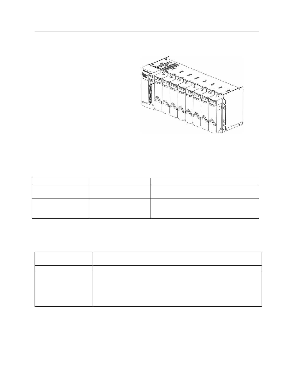
ControlWave I/O Expansion Rack (distinguishable from
ControlWave Process Automation Controller by lack of a key
switch)
Provides full instructions on setting up the
ControlWave I/O Expansion Rack hardware.
This document provides an overview of the
configuration process, with emphasis on
software setup.
25
Page 26

Setting up Redundancy Hardware
6
ControlWave I/O Switcher
NOTE: The full name for this device is the ControlWave Redundant I/O and Communications
Switch Unit, and it is abbreviated as CWREDIO, but we will refer to it simply as the
‘ControlWave I/O Switcher’, or just the ‘I/O Switcher’.
The ControlWave I/O Switcher can be used with ControlWave I/O Expansion Racks to provide
I/O Expansion Rack Redundancy. When used in this way, a host (master) controller must exist,
which could be a ControlWave Process Automation Controller, or a ControlWave Redundant
Controller.
The ControlWave I/O Switcher can also be used together with two ControlWave Process
Automation controllers to provide Control Redundancy and Local I/O Redundancy.
Full instructions on setting up the I/O Switcher are included in the ControlWave Redundant I/O
and Communications Switch Unit manual CI-ControlWaveREDIO.
We will provide a brief overview of the major configuration steps, with references to where in
the hardware manual, you can find additional information.
2
Page 27

Setting up Redundancy Hardware
7
Overview of I/O Switcher Hardware Configuration
This involves unpacking the I/O Switcher hardware, mounting the chassis, configuring and
installing the various hardware modules, installing interconnect cables between each
ControlWave Process Automation Controller or each ControlWave I/O Expansion Rack and the
I/O Switcher, wiring I/O terminations, making proper ground connections, and wiring the
ControlWave Power Supply/Monitor Modules (PSMMs) to bulk power supplies.
In the discussion, below, the “A” and “B” ControlWave units refer to the redundant pair of
ControlWave Process Automation Controllers or ControlWave I/O Expansion Racks, which are
having I/O controlled via the ControlWave I/O Switcher.
To install and configure the ControlWave I/O Switcher follow steps 1 through 10 below:
1. Remove the Chassis from its carton and install it at its assigned work site (see Section 2.3.1 of
manual CI-ControlWaveREDIO).
2. Remove the power supply modules and the control module from their cartons and install them
into their designated slots (see Figure 2-6 of manual CI-ControlWaveREDIO). There are two
power supply modules (called PSSM), and one Redundancy Control Module (called IORCM).
3. Connect the Redundant ControlWave Communication Cables as follows:
Connect one end of Cable A to Comm. Ports 1 through 4 of the “A” ControlWave unit, and
the other end to Comm. Interface Connector J5 of the Redundancy Control Module (IORCM)
on the ControlWave I/O Switcher.
Connect one end of Cable B to Comm. Ports 1 through 4 of the “B” ControlWave unit and the
other end to Comm. Interface Connector J6 of the Redundancy Control Module (IORCM) on
the ControlWave I/O Switcher.
4. Connect network communications cables to the Redundancy Control Module (IORCM) as
follows (see Section 2.3.1.3 of manual CI-ControlWaveREDIO):
Comm. Port 1 = J1 - RS-232
Comm. Port 2 = J2 - RS-232
Comm. Port 3 = J3 - RS-232 or RS-485 (factory configured per order)
Comm. Port 4 = J4 - RS-232 or RS-485 (factory configured per order)
5. Remove the I/O Switch Modules (IORSM) from their cartons and install them into their user
assigned positions in the Chassis. There are from one to eight I/O Switch Modules, which
reside in slots 2 through 9 and mate with Backplane Connectors P4 through P11 respectively.
Install I/O wiring to each one (see Section 2.3.2 of manual CI-ControlWaveREDIO).
2
Page 28

Setting up Redundancy Hardware
6. Install a ground wire between the Chassis Ground Lug and a known good Earth Ground (see
Section 2.3.1.1 of manual CI-ControlWaveREDIO).
7. Install switchover control wires (not provided) between IORCM pluggable terminal block
connectors TB1 and TB2 to connector TB1 on the PSSMs of both the “A” and “B”
ControlWave units (see Section 2.3.3.3 of manual CI-ControlWaveREDIO).
8. Remove the Power Supply Panel Cover and connect Bulk DC Power to the pluggable terminal
block connector TB1 on each of the two PSMMs (see Sections 2.3.3.1 & 2.3.3.2 of manual
CI-ControlWaveREDIO). Note: It is recommended that the pluggable terminal block (TB1)
associated with each PSMM not be connected until the entire system has been wired and
configured. When ready turn both PSMMs to their ON position via SW1 ( ‘I’ pressed) on each
PSMM.
9. Install the Power Supply Panel Cover removed in step 8. This item is screwed into place (see
Section 2.3.4 of manual CI-ControlWaveREDIO).
10.Configure each of the “A” and “B” ControlWave units associated with I/O Switcher and
apply power to them by setting the Power Switch on their PSSM Modules to the ‘I’ position.
Note: Both the “A” and “B” ControlWave units must be identical (except for IP addresses and
the position of CPU switch SW1-7) and must be equipped with Rev. B or higher CPU Boards
that are running with ControlWave firmware (Rev. 4.10 or higher).
28
Page 29

Establishing Communications
Fi
Establishing Communications
Communications between the PC and the ControlWave hardware (Controller, Redundant
Controller, or I/O Expansion Rack) can be established using either LocalView or NetView.
(LocalView is generally easier for first time users.)
For the ControlWave Controller, ControlWave Redundant Controller, or ControlWave I/O
Expansion Rack, you should plug the cable into the communication port in the associated
redundancy hardware, i.e. the port on the CCRS of the ControlWave Redundant Controller, or
the port on the IORCM of the ControlWave I/O Switcher.
For the Controlwave I/O Expansion Rack, if you are using RS485, the port you plug into must be
the one associated with COM1, and you must also enable diagnostics mode by setting switch
SW1-8 on the I/O Expansion Rack to ON. This will set COM1 on the rack to 9600 baud, 8 bits, 1
stop bit, no parity, allowing you to configure flash parameters.
Establishing Communications Using LocalView
Step 1. Click as follows: StartÆProgramsÆOpenBSI ToolsÆLocalView
Step 2. Choose 'Local' for the mode, enter a
name for the LocalView file, and click on
[Create].
Step 3. Choose the communication port on the PC
workstation which you will use to
communicate with the ControlWave
unit. Then, specify the baud rate for
that port, and click on the [Next>] button.
rst, choose
'Local' as
the mode.
Choose the communication port on
workstation
Specify the baud rate for that port
Next, enter a
name for this
LocalView
file.
(NOT on the ControlWave)
Finally, click
on
[Create]
the PC
Finally, click on
29
[Next>]
Page 30

Establishing Communications
n
Step 4. First, turn off auto local address detection by answering "No" to the question. Then
specify '1' as the local address. For the RTU Type, choose ‘ControlWave’ if this is a
ControlWave Redundant Controller, or ControlWave Process Automation Controller. If
this is a ControlWave I/O Expansion Rack, choose ‘CWave_RIO’. Finally, click on
[Finish].
Turn off auto local
Choose
'ControlWave' or
‘CWave_RIO’
address detection
Use "1" as the
local address
Finally, click on
Step 5. At this point, LocalView will create a temporary network with a single ControlWave icon
called, generically, 'RTU'. Right-click on the icon, then choose RTUÆ RTU
Configuration Parameters from the pop-up menus.
[Finish]
Right-click on the ControlWave ico
Step 6. The Flash Configuration Utility will appear. See 'Setting Flash Parameters', later in th is
manual.
30
Page 31

Establishing Communications
Establishing Communications Using NetView (ControlWave Already In a Network)
IMPORTANT: This method assumes that the ControlWave unit has already been included in an
Open BSI network within the NetView program, and that it has been configured
to communicate over that network's communication line as described in the Open
BSI Utilities Manual (document# D5081).
Step 1. Click as follows: StartÆProgramsÆOpenBSI ToolsÆNetView
Step 2. Right-click on the ControlWave icon, in the NetView network tree, and choose
RTUÆRTU Configuration Parameters from the pop-up menus.
Right-click on the
ControlWave icon
Step 3. The Flash Configuration Utility will appear. See 'Setting Flash Parameters', later in th is
manual.
31
Page 32

Setting Flash Parameters
Setting Flash Parameters
The Flash Configuration Utility may be accessed either through NetView or LocalView. In either
case, it allows the user to specify all the major configuration parameters of the ControlWave
unit. As part of this manual, we will only discuss those parts of the Flash Configuration Utility
which are important for configuration of redundancy. A full discussion of the Flash
Configuration Utility is included in Chapter 5 of the Open BSI Utilities Manual (document#
D5081).
The various configuration settings are separated into different pages of the utility. You can
access them by clicking on the tab for a particular page. The pages associated specifically with
configuration of redundancy are:
• Ports - this includes all communication ports on the ControlWave units - up to four serial
ports (COM1 through COM4), and three Ethernet IP ports. In order to configure redundancy,
an Ethernet Port MUST be configured for each unit.
• Application Parameters – Most of these are 'tuning' parameters which govern how the
ControlWave executes its application (project), however, there are some directly related to
redundant operations.
32
Page 33
Setting Flash Parameters
Before you Begin
• For purposes of this explanation, we are going to configure unit ‘A’ first, therefore, the
‘A/B/Enable’ switch (located on the CCRS of the ControlWave Controller, or on the
Redundancy Control Module (IORCM) of the ControlWave I/O Switcher) should be set to
‘A’, and unit ‘A’ should be powered on. If the unit has a project already running in it, its
display should be blank; if not “00” should appear on the display.
• We are assuming, at this point, that you have successfully established communications with
the ControlWave using either LocalView or NetView.
Signing on to the ControlWave
Click on the [Sign On] button, then enter a username
and password to sign on to the ControlWave. If this is
the first time you are signing on, and no user accounts
have been defined, use “SYSTEM” for the username,
and “666666” as the password.
NOTE: If you do NOT sign on, the first time you
attempt a read/write operation, you will be prevented
from doing so, and will be prompted to sign on then.
Once you have signed on, you can proceed to the ‘Ports’ page by clicking on the ‘Ports’ tab.
Setting Up an Ethernet Port
ControlWave redundant data is transferred via IP communications, therefore a ControlWave
CPU must have at least one Ethernet Port defined.
33
Page 34

Setting Flash Parameters
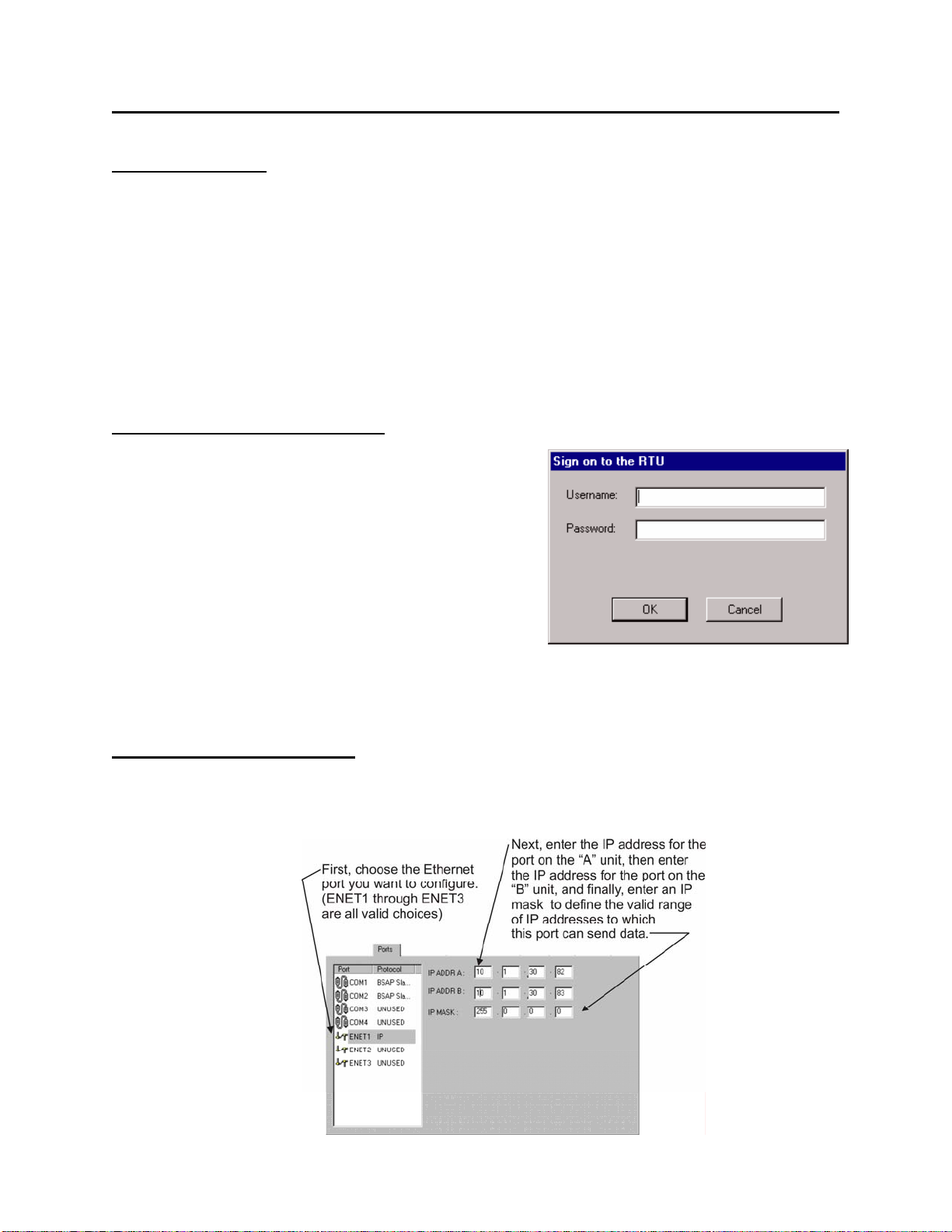
Step 1. Click on the 'Ports' tab, if you haven't already.
Step 2. Choose the Ethernet port you want to configure (ENET1, ENET2, or ENET3 are valid
choices.)
Step 3. Specify an "IP ADDR A" (the IP address for the chosen Ethernet Port on the “A” unit),
and “IP ADDR B” (the IP address for the corresponding Ethernet Port on the “B” unit),
and an "IP MASK" which defines the range of addresses reachable through this port. IP
addresses must be unique within your network. Conversely, IP masks are typically the
same for all devices in the same portion of a network. Together, the IP Address and IP
Mask define a range of addresses to which this port can send messages. (See
'Recommended Ranges for IP Addresses' later in this document.) Basically, a non-zero
value in any of the "IP MASK" fields indicates that the corresponding "IP ADDR A"
and “IP ADDR B” field is specifying a portion of the IP address which must be
identically matched with every destination IP address to which this port will send
messages. A zero value in any of the "IP MASK" fields means that this communication
port can send messages to addresses in which any integer from (0 to 255) is considered
valid for that corresponding portion of the destination IP address.
In newer ControlWave units, all Ethernet ports are pre-programmed at the factory
with initial IP addresses and masks, as follows:
Because each unit shipping from the factory will have these initially preprogrammed, you should only use these addresses for ‘bench’ testing and
configuration. These addresses must be changed before putting ControlWave units
on an actual network, since an address conflict would exist as soon as the second
ControlWave unit was placed online.
In the figure on the previous page, the "IP ADDR A" is 10.1.30.82, the “IP ADDR B”
is 10.1.30.83, and the "IP MASK" is 255.0.0.0. This means that this port can send to any
address in the format 10.x.y.z where x, y, and z, are any integer from 0 to 255. So,
10.43.127.76 and 10.84.35.93 would be valid destinations, but 24.1.1.1 would not
because the 255 in the "IP MASK" indicates that the corresponding portion of the "IP
ADDR A" and “IP ADDR B” MUST be 10.
ETH1 IP Address: 10.0.1.1 IP Mask: 255.255.255.0
ETH2 IP Address: 10.0.2.1 IP Mask: 255.255.255.0
ETH3 IP Address: 10.0.3.1 IP Mask: 255.255.255.0
IMPORTANT
34
Page 35

Setting Flash Parameters
There are other restrictions, for example, the non-zero mask entries must be all be in
contiguous fields, and must begin in the left-most portion of the address. More details on
these subjects are included in the Open BSI Utilities Manual (document# D5081).
NOTE: If you are using a direct Ethernet connection (no hub involved) between the two
units, you should configure IP addresses which are completely different from any other
Ethernet ports you have configured for the unit, and you should choose a mask which
limits the transmission to just between the two Ethernet ports used for redundant
operations, e.g. 255.255.255.248 will force “IP ADDR A” and “IP ADDR B” to match
exactly except for the last three bits of the address.
Step 4. At this point, you can proceed to configure additional ports (Ethernet, BSAP, etc.). When
finished defining ports, please click on the ‘Application Parameters’ tab, to go to the
Application Parameters page.
Recommended Ranges for IP Addresses
If you are intending to connect your Open BSI network directly to the global world-wide
Internet, you must obtain a range of IP addresses from your Internet service provider (ISP) or
from an Internet governing body such as the Internet Assigned Numbers Authority (IANA).
If you have no plans to connect your network to the global Internet, there is no restriction on
your choice of IP addresses, however, the Internet Engineering Task Force recommends, as per,
RFC 1918* that IP addresses for private networks should be assigned from the following ranges:
10.0.0.0 to 10.255.255.255
172.16.0.0 to 172.31.255.255
192.168.0.0 to 192.168.255.255
These particular ranges of Internet addresses have been set aside for private networks. Any
messages coming from these addresses can be recognized by most Internet Service Providers
(ISP) as coming from private networks, and so can be filtered out. This helps avoid addressing
conflicts should an accidental connection occur between a private network, and the global
Internet.
Devices (e.g. controllers, workstations) in Bristol Babcock networks always use fixed IP
addresses. This causes certain complexities if you choose to use Dynamic Host Configuration
Protocol (DHCP) in your network. Because DHCP assigns IP addresses dynamically, as they are
needed, you must examine your DHCP server to determine the addresses which have been
assigned for each Bristol controller or workstation, and then manually enter those addresses in
*
Rekhter, et al, Best Current Practice memo - "Address Allocation for Private Internets", Internet Engineering Task
Force, RFC 1918, February, 1996. Please see http://www.ietf.org for complete text of this memo.
35
Page 36

Setting Flash Parameters
6
NetView. You should then specify the longest possible lease time for the addresses, to help
prevent the loss of a given address through a device failure.
It is also strongly recommended that the DHCP server is configured such that the addresses
reserved for the Bristol controllers are permanently reserved (by tying them to the RTU MAC
addresses within the DHCP configuration or by having them in a totally different address range).
The same should be done when configuring RAS servers or other machines capable of providing
dynamic addressing information. Otherwise, you can easily have duplicate IP addresses on your
network.
Setting Application Parameters for Redundancy
Click on the ‘Application Parameters’ tab. Specify the IP addresses for unit "A" and unit "B".
These must correspond to the IP addresses you defined earlier for these units' respective Ethernet
ports.
Here you must enter the IP addresses
of both the “A” and “B” units in the
redundant pair. These addresses would
correspond to Ethernet ports configured
for each ControlWave. These addresses
MUST be different.
Setting other Flash Parameters
Additional Flash Parameters (user accounts, soft switches, audit/archive parameters, etc.) may
need to be defined, depending upon your particular user application. These should be done,
before proceeding.
If configuring I/O Expansion Racks, various timeouts must be defined, plus MODBUS users
must set certain parameters. See the ControlWave I/O Expansion Rack Quick Setup Guide
(document# D5122) for details.
For information on configuring parameters on other pages of the Flash Configuration utility,
please see the ControlWave Quick Setup Guide (document# D5084) and Chapter 5 of the Open
BSI Utilities Manual (document# D5081).
3
Page 37
Setting Flash Parameters
7
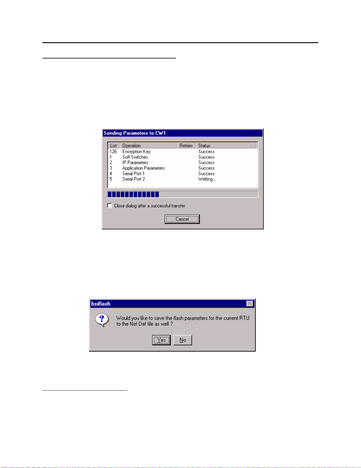
Saving the Flash Parameters to the Unit
When you’ve finished setting the Flash parameters, you must save them to the ControlWave unit,
in this case, unit A.
Click on the [Save to Rtu] button. This button saves ALL entries in the pages of the Flash
Configuration Utility to the ControlWave unit. NOTE: If you haven't signed on prior to clicking
on this button, you will be prompted to do so.
You will also be prompted whether or not to save these changes to the NETDEF file. Choosing
‘Yes’ in answer to this prompt avoids the need to re-enter the same configuration information in
NetView. This operation will only work when the Flash Configuration Utility is invoked from
within NetView or when LocalView is in Configure Mode; otherwise a permanent NETDEF file
is not available to write to6.
6
The reason other LocalView modes (e.g. 'Local' ) cannot perform these operations is that only 'Configure' mode
actually allows the user to specify a particular NETDEF file for modification (by checking the “Use an Existing
Configuration (.ndf) File” and then identifying the path and name of the NETDEF.) The other modes utilize a
temporary NETDEF which disappears on program exit.
3
Page 38

Setting Flash Parameters
Activating the newly saved parameters
After you have completed setting parameters on all the various pages of the Flash Configuration
Utility, you must save those entries to the ControlWave unit by clicking on the [Save to Rtu]
button. The new entries will be sent to the FLASH memory of the ControlWave unit.
For most of the parameters, the changes will NOT become active until you have reset the unit,
thereby forcing the parameters to be read by the system.
To reset the ‘A’ unit, power it OFF, and then back ON.
NOTE: If, after doing this, the new parameters still have not taken effect, make sure switch
SW1-3 was NOT incorrectly set to the OFF position. Switch SW1-3 must be ON (its
default position) for new FLASH parameters to be read.
Saving the same parameters to the other unit:
At this point, you have fully programmed the FLASH parameters for only one unit in the
redundant pair.
In order to act redundantly, the other unit must have an identical configuration. To do this, turn
the A/B Enable key switch on the CCRS or IORCM to ‘B’. Next, power on the other unit (in this
case ‘B’), and wait until its display shows either “00” (which indicates it has no project loaded),
or a blank screen (which indicates a project is loaded and running). NOTE: I/O Expansion Racks
don’t contain ControlWave projects, but their display will appear blank if they are operating
properly.
Click on [Save to Rtu] and the same parameters you saved on ‘A’ will be transferred to the ‘B’
unit. Turn OFF the power to unit ‘B’, then turn it back ON, and the new parameters will be
activated. You can now click on [Close] to exit the Flash Configuration Utility.
38
Page 39

Ethernet Connection Redundancy
Ethernet Connection Redundancy
In NetView, a single node (RTU) must be defined for the ControlWave Redundant Controller, or
pair of ControlWave Process Automation Controllers with an I/O Switcher.
This node will have two IP addresses "Primary Address" and "Secondary Address" which
correspond to IP addresses used to communicate with the controller. Typically, you would set
these to correspond to the ‘A’ and ‘B’ Ethernet Ports you defined for redundant transfer, but they
could be other Ethernet Ports you defined for the same node. You should also choose
"Symmetric Fallback"; this allows Open BSI to switchover to the alternate address if
communications are not possible on the current address. For more information on setting up
RTUs in NetView, see Chapter 6 of the Open BSI Utilities Manual (document# D5081).
Symmetric Fallback should be
chosen
39
Page 40
Testing the Redundant Setup (CPU and Power Supply)
C
ariables
Testing the Redundant Setup (CPU and Power Supply)
Before Testing Redundancy
Before attempting to test the redundant setup, it is recommended that you verify that each
ControlWave unit functions properly as a single stand-alone unit, by plugging in directly, and
attempting to communicate. Only when both ControlWave units have been successfully tested
operating in stand-alone mode, should redundancy testing begin.
Using the Sample Redundant Project or Creating Your Own Redundant Project
RDNSAMPLE.ZWT is a zipped sample redundant project that is automatically installed in the
\OPENBSI\PROJECTS directory of your PC when you install the ControlWave Designer kit. It
is configured with redundancy status variables for monitoring the status of redundant operations.
NOTE: Any ControlWave project can serve as a redundant project, without changes, however, it
is recommended that the project be configured with redundancy status variables (such as in
RDNSAMPLE.ZWT) so that status and statistics regarding redundant operation can be viewed.
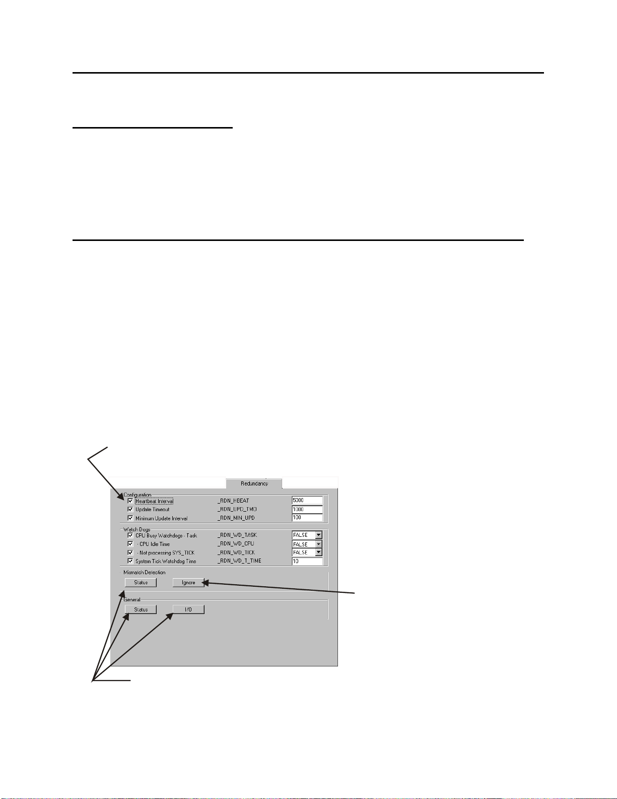
To add redundancy status variables to an existing project, call up the System Variable Wizard by
clicking on ViewÆSystem Variable Wizard, in ControlWave Designer, and check the
redundancy status variables on the ‘Redundancy’ page. See ‘Redundancy Status Variables’ later
in this manual for a description of each redundancy variable.
heck the boxes next to the various redundancy
variables to include them in your project.
This push button calls up a page
of redundancy variables which,
if selected, cause certain conditions
to be treated as ‘warnings’ instead
of ‘errors’ which would stop
redundancy from working.
These push buttons call up
additional pages of redundancy
v
.
40
Page 41

Testing the Redundant Setup (CPU and Power Supply)
Testing the Redundant Setup
NOTE: This test procedure does NOT address the subject of I/O Expansion Rack testing, since,
with the exception of power failure watchdog conditions, that is subject to user-defined criteria.
This test assumes the following:
• Unit “A” is already powered-on, and has been chosen as the primary unit using the Primary
switch on the CCRS or IORCM. (If you prefer to use “B”, substitute “A” for “B” and “B”
for “A” accordingly.)
• For this testing, your PC should be plugged into serial port COM2 of the CCRS or IORCM.
• The A/B Enable key switch is in the center position, i.e. automatic (not on ‘A’ or ‘B’).
The ControlWave Redundant Controller (or pair of ControlWave Controllers operating
redundantly) should NOT be connected to a running plant or process during this testing.
Safeguards must be taken prior to downloading to ensure that the controller is isolated
from the process and I/O is disconnected. Failure to take such precautions could result in
injury to persons or damage to property.
1. Power-ON the “B” unit, and wait for ‘BD’ to appear on the display.
2. Start ControlWave Designer, and open/unzip the project you want to use in the
ControlWave controller. (This could be the RDNSAMPLE project discussed earlier, or
another project you made yourself.)
3. Establish communications between
ControlWave Designer and the ControlWave
controller.
• Right-click on the RTU_RESOURCE in
the project tree, and choose "Settings"
from the menu. The Resource Settings
dialog box will appear.
• In the Resource Settings dialog box,
choose "DLL" for the 'Port'.
• Choose 'Serial' from the "DLL:" list box.
WARNING:
Right-click on the resource, and
choose from the menu.
"Settings"
41
Page 42

Testing the Redundant Setup (CPU and Power Supply)
d
• Specify the PC communication port (e.g. COM1), the baud rate, and the timeout in
milliseconds. For this example, we are using COM1, 9600 baud, 2000 millisecond
timeout.
Choose
"DLL"
Choose
"Serial"
Click on
[Ok]
when finishe
Specify the COM port, baud rate, and timeout (in msec)
• Click on [OK].
• Click on the 'Project Control Dialog' icon, and the RTU_RESOURCE dialog box will
appear.
Click on the ‘Project Control Dialog’ icon
42
Page 43

Testing the Redundant Setup (CPU and Power Supply)
t
4. Download the boot project into the ControlWave Redundant Controller (or ControlWave
Process Automation Controller belonging to a redundant pair).
• Click on [Download] in the RTU_RESOURCE
dialog box. The Download dialog box will appear.
• Now it is necessary to download the boot project into the controller. Since “A” is the
primary, the download will go to the “A” unit. In the Download dialog box, click on
[Download] in the ‘Bootproject’ section.
Click on to download the boot projec
[Download] .
Click on [Download]
43
Page 44

Testing the Redundant Setup (CPU and Power Supply)
C
• The download will not proceed if you
are not signed on. If you are not already
signed on, sign-on to the ControlWave,
by entering the username "SYSTEM"
and the password "666666" in response
to the Login prompt, then click on
[OK]. (NOTE: SYSTEM is a default
security account which is included in
the ControlWave when it ships from
the factory, so that you can access the
ControlWave during initial
configuration, before any other user
accounts have been defined.)
5. Activate the boot project, by clicking on the [Activate] button in the Download dialog
box. (If the Download dialog box is not visible, you can recall it by clicking on the
[Download] button in the RTU_RESOURCE dialog box.) As you activate the project,
the display on the “A” unit should show a ‘01’ code. Also, watch the display on the “B”
unit – it should momentarily show a ‘BC’ code as the side-load occurs, then a ‘BA’ code
when the side-load is complete. ‘BA’ (Backup Active) indicates that the “B” unit is
acting as the standby unit, and is ready to take over should the “A” unit fail.
lick here to activate the boot project.
44
Page 45

Testing the Redundant Setup (CPU and Power Supply)
6. At this point the “A” unit is loaded, but not yet running. Initiate
a cold start of the “A” unit by clicking on the [Cold] button in
the RTU_RESOURCE dialog box.
7. Now, enter Debug Mode in ControlWave Designer, by clicking on the debug
icon (shown at right)
8. Next, double-click on the Global_Variables worksheet in the tree, and locate the group
called SYS_VAR_WZ_DATA to view the system variables associated with redundancy.
In particular, look at the
variable called ‘_RDN_IS_B’,
and notice that it is FALSE.
9. Power-off the "A" unit, and
see if the "B" unit assumes
control as the new On-line
unit. (Momentarily, you will
see question marks for the
“Online value” of the
variables of the
SYS_VAR_WZ_DATA
group, then the screen will
refresh with data from the new
On-line unit.) The
‘_RDN_IS_B’ variable should
now show TRUE, verifying
that the “B” unit is now the
on-line unit.
45
Page 46

Notes on Redundant Operation
6
Notes on Redundant Operation
How do I force a fail-over to the Standby unit via program control?
IMPORTANT
If using Local I/O Redundancy, the only fail-overs (other than watchdog conditions) are
handled via the REDUN_SWITCH method, described, below. Users must define I/O failover criteria in their ControlWave project.
NOTE: To force a fail-over from one I/O Expansion Rack to another rack requires a
different method. See ‘Forcing I/O Expansion Rack Fail-over’.
If desired, the user can trigger a redundant fail-over from On-line unit to the Standby unit based
on conditions detected in the software.
To do this, users must incorporate the REDUN_SWITCH function into their project.
Excerpts from a POU using the REDUN_SWITCH function block in structured text (ST) are
shown below. Comments appear in italics:
IF (SWITCHNOW) We are putting this at the top of the POU. If SWITCHNOW is TRUE a failover occurs
right at the top. This ensures that failover doesn’t occur in the middle of the POU, which
would cause all changes within that execution cycle to be lost.
THEN
RDSTAT:=REDUN_SWITCH(SWITCHNOW);
SWITCHNOW:=FALSE;
;
ENDIF;
:
: the main body of the POU would appear here. Somewhere in here, a test to determine
: whether a failure has occurred requiring a switchover must be made. The condition causing the
failure can be anything the user chooses.
FAILURE:= some failure condition logic must be added here
:
:
IF (FAILURE) At the bottom of the POU, if the FAILURE condition, determined in the main body is
TRUE, then SWITCHNOW is set TRUE, so at the top of
the next execution cycle, the fail-over will occur.
THEN
SWITCHNOW:=TRUE;
ELSE
SWITCHNOW:=FALSE;
ENDIF
FAILURE:=FALSE;
In the structured text code, we use the REDUN_SWITCH function block, which takes the format
4
Page 47

Notes on Redundant Operation
7
S
statuscode:=REDUN_SWITCH(ibEnable)
Whenever the ibEnable variable is TRUE, a fail-over will be attempted immediately.
Some other things you should be aware of when using the REDUN_SWITCH function block:
• When using the REDUN_SWITCH function block, the condition that forces the fail-over, in
this case, the FAILURE variable, should be a local, non-retain variable. The reason for this is
that if the variable is retained, there is a possibility of repeated switchovers between A and B
since the same failure condition value would be transferred from the on-line to the standby,
causing the new on-line unit to try to fail back, and so on.
• As soon as the REDUN_SWITCH function block executes with a TRUE ibEnable variable,
the fail-over process begins immediately, no additional lines of code in the task are executed.
For this reason, we recommend that the REDUN_SWITCH function block always be placed
at the very beginning of the POU, to prevent a switchover in the middle of partial
calculations, which would have to be discarded (see next item).
The following items apply whether or NOT you are using REDUN_SWITCH in your
redundant system:
• Whenever an application-level task completes its
execution cycle, an update occurs. (In an update, all
changes to retain variables, I/O, historical data, etc.
On-Line Unit
RETAIN
VARIABLES
tandby Unit
RETAIN
VARIABLES
are sent to the standby unit, to keep it up-to-date.) If
a fail-over occurs somewhere during the task’s
I/O
I/O
execution, changes resulting from that particular
task execution will NOT be sent to the backup.
(Partial updates can occur, however, if there is an
overlap in the execution cycles of more than one
task. As soon as the first of the overlapping tasks
completes execution, an update of ALL changes to
retain memory, historical data, I/O, etc. will be sent
to the standby unit, even for items which were
partially updated by the task which did not finish
HISTORICAL
DATA
At the completion of
the execution cycle of
ANY task, all changes
for these items are sent
from the online unit to
the standby unit; whether
or not they have to do with
that particular task.
HISTORICAL
DATA
yet.)
For this reason, although you can have multiple program POUs in your project, we
recommend that in a redundant system, you confine all your program POUs to a single
executing task. This is because one or more tasks may not have completed an execution
cycle when the fail-over occurs, thereby resulting in incomplete updates to the standby. (The
partial updates issue is equivalent to the situation that occurs if you power fail the unit, and
then a warm start occurs.)
4
Page 48
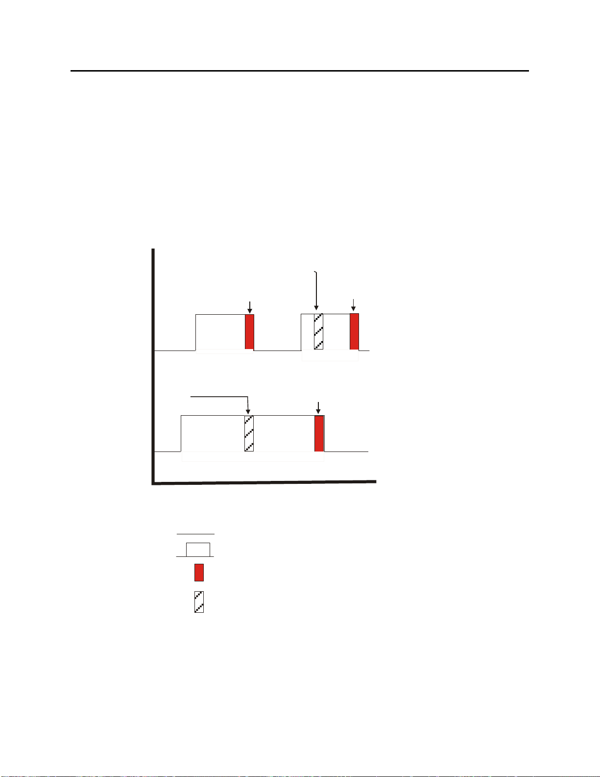
Notes on Redundant Operation
;
• Another reason you may want to use only a single task in a redundant system, is that the
greater the number of tasks, the more frequently CPU execution of application-level tasks
will be suspended for updates. This is because after each task completes, the CPU will
suspend execution of all application-level tasks in your project to allow updates to be
transferred to the standby unit. Once the transfer is complete, the next task is allowed to
execute and complete execution, and ALL application-level asks will be suspended again
while its updates are transferred to the standby unit, and so on. As you can see, the more
tasks, the more time execution of all tasks is suspended. To see a measurement of how often
execution is suspended, check the _SUSP_PERCENT system variable.
End of this Task 1’s cycle;
update the standby
TASK 1
Task 2’s execution
is suspended while the
update of the standby
occurs.
T ASK 2
TIME
Legend:
= task idle
= high indicates task is executing
= update from on-line to standby
is in progress
= execution suspended while
update is in progress
• If a fail-over occurs while an update of the standby is in progress, the entire update is
considered incomplete, and is therefore discarded.
Task 1’s execution is suspended
while the update of the standby
occurs.
End of this Task 1’s cycle
update the standby
End of this Task 2’s cycle;
update the standby
48
Page 49
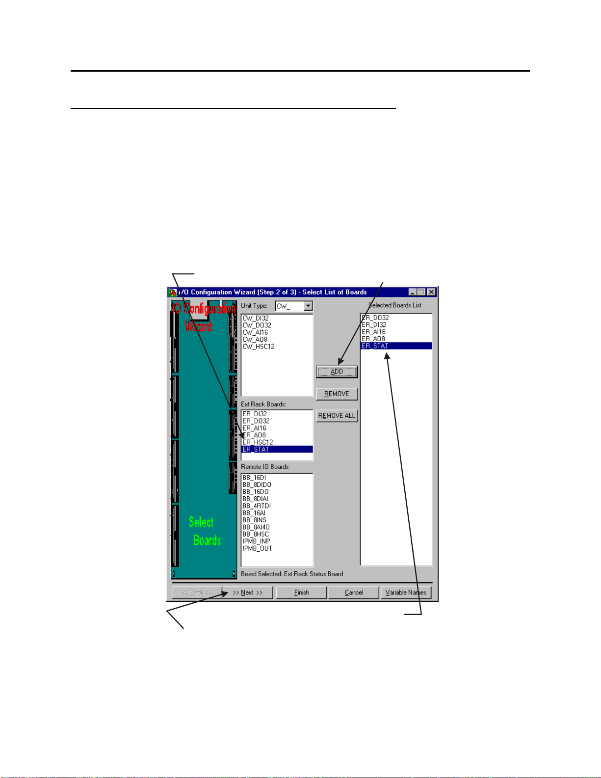
Notes on Redundant Operation
C
Forcing I/O Expansion Rack Fail-over via Program Control
Failures in the I/O Expansion Rack, other than those caused by watchdog conditions, can only be
forced via a variable on the ER_STAT board. (The ER_STAT board is a virtual board, not a
physical board. It must be defined in the project running in the ControlWave host, like any other
board for the ControlWave I/O Expansion Rack.)
To configure this fail-over mechanism in the ControlWave project, do the following:
1. In ControlWave Designer’s I/O Configuration Wizard, include the ER_STAT virtual
board.
hoose ‘ER_STAT’ then click
[ADD]
When the board gets added to the list,
click on
[Next]
49
Page 50

Notes on Redundant Operation
S
x
2. Check the “Redundant Expanded Rack” box, then click on [Finish].
elect the Redundant Expanded Rack bo
This must be the
IP address of the
“A” unit in the pair
of I/O Expansion
Racks.
You should always
associated I/O boards
with a particular task,
to ensure efficient data
update rates.
Click on
[Finish]
50
Page 51
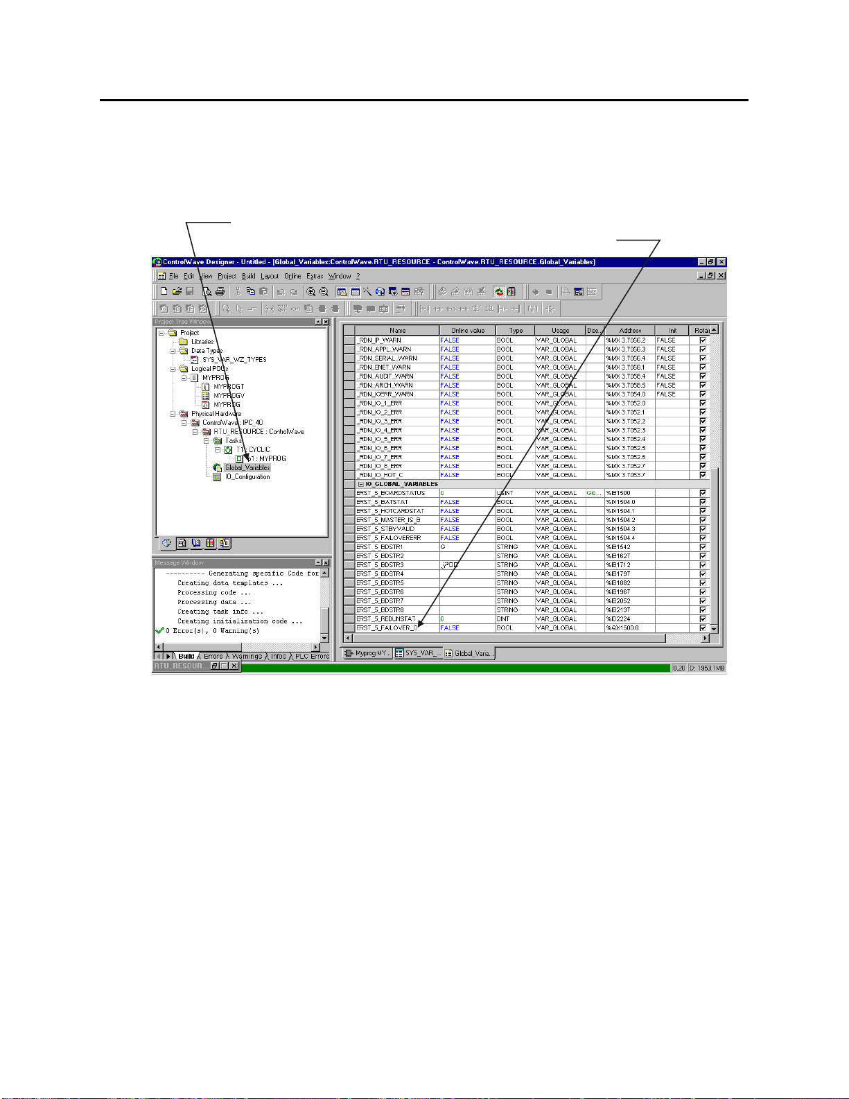
Notes on Redundant Operation
,
3. Double-click on the RTU_RESOURCEV item in the project tree. Several variables
related to the ER_STAT board will be present. The ERSTAT_x_FAILOVER_O variable
is a BOOL, that you can set TRUE, to force a fail-over.
Double-click on the Global_Variables item in the project tree
and you can see the variables created for the ER_STAT board.
4. In your project, include code to test for whatever failure condition you want to cause a
fail-over to the standby I/O Expansion Rack. Excerpts from a POU in structured text (ST)
are shown below. Comments appear in italics:
FAILURE:= some failure condition logic must be added here
::
IF (FAILURE)
ERSTAT_4_FAILOVER_O:=TRUE;
ENDIF
THEN
If for some reason, a fail-over cannot occur (either because the standby is not present, or there is
some other error, the variable ERSTAT_x_FAILOVERERR will automatically be set to TRUE.
51
Page 52
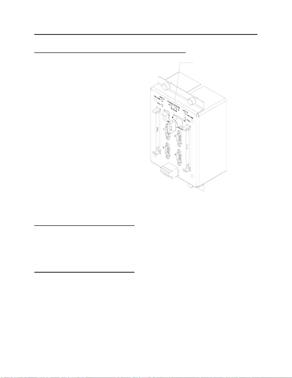
Notes on Redundant Operation
)
How do I manually force a fail-over to the Standby unit?
There are certain circumstances in
which you might want to manually failover from the On-line unit to the
Standby unit. The most common
situation would be if you need to
perform some service or repair to the
On-line unit, and therefore, you need to
take it 'off-line' and have the Standby
take over while the service or repair is
being performed.
To force a manual fail-over, you can
simply change the position of the A/B
Enable key switch on the CCRS or
IORCM to select the unit which is
currently the Standby unit; it will then
become the new On-line unit.
J5
J1
J2
J3
J4
J7
A/B Enable d k e y Switch
(Shown in automatic mode
J6
CCRS shown (IORCM is similar)
Manually failing over from "A" to "B"
If the "A" unit is currently the On-line unit, and you want to manually fail-over to the Standby
unit "B", move the A/B Enable key switch on the CCRS or IORCM to the "B" position (right).
The "B" unit will now be the new On-line unit.
Manually failing over from "B" to "A"
If the "B" unit is currently the On-line unit, and you want to manually fail-over to the Standby
unit "A", move the A/B Enable key switch on the CCRS or IORCM to the "A" position (left).
The "A" unit will now be the new On-line unit.
52
Page 53

Notes on Redundant Operation
Return the A/B Enable Key Switch to Automatic Mode
Once you have re-activated the controller which you were performing service on, we recommend
that you set the A/B Enable key switch to the automatic position (center). This will allow an
automatic fail-over back to the previous standby unit, if the current on-line unit should fail.
Specifying a New Primary Unit
The Primary switch on the CCRS or IORCM determines which ControlWave unit should be the
on-line unit on power-up. Set it to either ‘A’ for unit A, or ‘B’ for unit B. The selected unit will
be the new primary unit the next time the redundant system is re-booted.
IMPORTANT
If the ControlWave I/O Switcher should suffer its own power failure, the position of the
Primary switch is ignored, and the “A” unit will automatically become the primary.
Codes Which Appear on the Standby Unit Display
The Standby unit displays codes which indicate the state it is in with respect to redundant
operation. These codes are shown in the table, below:
Code Explanation
BA Backup Active – The standby CPU is ready to
take over should a failure occur at the on-line
unit.
BC Backup Copying – A sideload is in progress
between the on-line unit, and the standby unit.
BD Backup Down – The standby CPU is NOT
available. Typically there is some mismatch
between it, and the on-line CPU.
53
Page 54

Redundancy Status Variables
Redundancy Status Variables
The Redundancy Status Variables are defined using the System Variable Wizard. This section is
included for reference purposes only. NOTE: None of the variables shown here apply to the
ControlWave I/O Expansion Rack.
Variable Name Memory address Description
_RDN_STATUS AT %MD 3.7000 : DINT Last status returned from
redundancy. 0 = success;
negative values indicate error.
_RDN_STBY_CONN AT %MX 3.7004.0 : BOOL If set, the IP connections have
been established with the
redundant standby unit.
_RDN_STBY_VAL AT %MX 3.7004.1 : BOOL If set. the Standby unit has been
side-loaded, and is ready to take
over.
_RDN_IS_B AT %MX 3.7004.2 : BOOL If set, the current controller is
marked as unit 'B'.
_RDN_BOOTP_MIS AT %MX 3.7005.0 : BOOL If set, the BOOT project cannot
warm start. This value may be
set even if redundancy is not
active.
_RDN_CFG_CHG AT %MX 3.7005.1 : BOOL If set, it indicates a change to
FLASH configuration has
occurred.
_RDN_DEFLT_CFG AT %MX 3.7005.2 : BOOL If set, indicates the unit is
running with soft switches
disabled (SW1-3 in the OFF
position). Factory defaults are
used, instead.
_RDN_CFG_MIS AT %MX 3.7005.3 : BOOL There is a configuration
mismatch in the FLASH
between the on-line unit, and the
standby unit.
_RDN_SEC_MIS AT %MX 3.7008.0 : BOOL There is a mismatch in security
parameters between the on-line
unit, and the standby unit.
_RDN_SW_MIS AT %MX 3.7008.1 : BOOL There is a mismatch in soft
switches between the on-line
unit, and the standby unit.
_RDN_IP_MIS AT %MX 3.7008.2 : BOOL There is a mismatch in IP
parameters between the on-line
unit, and the standby unit.
54
Page 55

Redundancy Status Variables
Variable Name Memory address Description
_RDN_APPL_MIS AT %MX 3.7008.3 : BOOL There is a mismatch in
application parameters between
the on-line unit, and the standby
unit.
_RDN_SERIAL_MIS AT %MX 3.7008.4 : BOOL There is a mismatch in serial
port parameters between the online unit, and the standby unit.
_RDN_ENET_MIS AT %MX 3.7010.1 : BOOL There is a mismatch in Ethernet
port parameters between the online unit, and the standby unit.
_RDN_AUDIT_MIS AT %MX 3.7010.4 : BOOL There is a mismatch in audit
configuration parameters
between the on-line unit, and the
standby unit.
_RDN_ARCH_MIS AT %MX 3.7010.5 : BOOL There is a mismatch in archive
file configuration parameters
between the on-line unit, and the
standby unit.
_RDN_HBEAT AT %MD 3.7028 : DINT
:= 5000
_RDN_UPD_TMO AT %MD 3.7032 : DINT
:= 1000
_RDN_MIN_UPD AT %MD 3.7044 : DINT
:= 100
_RDN_SL_COUNT AT %MD 3.7036 : DINT This is the number of times that
_RDN_SL_TIME AT %MD 3.7040 : DINT This is the number of
_RDN_WD_TASK AT %MX 3.7048.0 : BOOL If set, the Master will attempt to
This is the interval (in
milliseconds) at which the
Master will check the validity of
the links to the Standby unit. The
default is 5 seconds, and may be
altered in 1 second increments.
This is the timeout (in
milliseconds) for data
transactions between the Master
and the Standby unit. It defaults
to 1 second.
This is the minimum time (in
milliseconds) between real-time
updates from the Primary unit to
the Standby unit. If an output has
changed, the transfer will occur
anyway. If set to 0, the default of
100 is used. If set to 1, an update
will be forced after every cycle.
the side-load process has been
started.
milliseconds taken to complete
the last side-load.
55
Page 56

Redundancy Status Variables
6
Variable Name Memory address Description
:= FALSE Fail Over if a task Watchdog
limit is exceeded.
_RDN_WD_CPU AT %MX 3.7048.1 : BOOL
:= FALSE
_RDN_WD_TICK AT %MX 3.7048.2 : BOOL
:= FALSE
_RDN_WD_T_TIME AT %MW 3.7050 : UINT
:= 10
_RDN_IO_1_ERR AT %MX 3.7052.0 : BOOL I/O card in slot #1 of the
_RDN_IO_2_ERR AT %MX 3.7052.1 : BOOL I/O card in slot #2 of the
_RDN_IO_3_ERR AT %MX 3.7052.2 : BOOL I/O card in slot #3 of the
_RDN_IO_4_ERR AT %MX 3.7052.3 : BOOL I/O card in slot #4 of the
_RDN_IO_5_ERR AT %MX 3.7052.4 : BOOL I/O card in slot #5 of the
_RDN_IO_6_ERR AT %MX 3.7052.5 : BOOL I/O card in slot #6 of the
_RDN_IO_7_ERR AT %MX 3.7052.6 : BOOL I/O card in slot #7 of the
_RDN_IO_8_ERR AT %MX 3.7052.7 : BOOL I/O card in slot #8 of the
If set, the Master will attempt to
Fail Over if the CPU overload
exception is raised.
If set, the Watchdog for the
system tick is enabled.
This is the maximum number of
milliseconds which can pass
before the system tick runs. The
tick can be delayed due to
excessive interrupts (or 'S' state)
or a Real Time Redundancy
update.
Standby could not be updated
(either not present or improper
type)
Standby could not be updated
(either not present or improper
type)
Standby could not be updated
(either not present or improper
type)
Standby could not be updated
(either not present or improper
type)
Standby could not be updated
(either not present or improper
type)
Standby could not be updated
(either not present or improper
type)
Standby could not be updated
(either not present or improper
type)
5
Page 57

Redundancy Status Variables
7
Variable Name Memory address Description
Standby could not be updated
(either not present or improper
type)
_RDN_IO_HOT_C AT %MX 3.7053.7 : BOOL A hot-card insertion or removal
was in progress at the Standby
when the last I/O update was
attempted.
_RDN_IOERR_WARN AT %MX 3.7054.0 : BOOL
:= FALSE:
_RDN_SEC_WARN AT %MX 3.7056.0 : BOOL
:= FALSE:
_RDN_SW_WARN AT %MX 3.7056.1 : BOOL
:= FALSE:
_RDN_IP_WARN AT %MX 3.7056.2 : BOOL
:= FALSE:
_RDN_APPL_WARN AT %MX 3.7056.3 : BOOL
:= FALSE:
_RDN_SERIAL_WARN AT %MX 3.7058.4 : BOOL
:= FALSE:
When set TRUE, I/O board
errors will only be reported as
warnings, instead of errors, and
so will NOT prevent redundant
operation.
When set TRUE, discrepancies
between the security
configuration in the on-line unit,
and in the standby unit, will be
reported as warnings, instead of
errors, and so will NOT prevent
redundant operation.
When set TRUE, discrepancies
between the soft switch settings
in the on-line unit, and in the
standby unit, will be reported as
warnings, instead of errors, and
so will NOT prevent redundant
operation.
When set TRUE, discrepancies
between the IP parameters in the
on-line unit, and in the standby
unit, will be reported as
warnings, instead of errors, and
so will NOT prevent redundant
operation.
When set TRUE, discrepancies
between the application
parameters in the on-line unit,
and in the standby unit, will be
reported as warnings, instead of
errors, and so will NOT prevent
redundant operation.
When set TRUE, discrepancies
between the serial port
configuration in the on-line unit,
and in the standby unit, will be
5
Page 58

Redundancy Status Variables
Variable Name Memory address Description
reported as warnings, instead of
errors, and so will NOT prevent
redundant operation.
_RDN_ENET_WARN AT %MX 3.7058.1 : BOOL
:= FALSE:
_RDN_AUDIT_WARN AT %MX 3.7058.4 : BOOL
:= FALSE:
_RDN_ARCH_WARN AT %MX 3.7058.5 : BOOL
:= FALSE:
When set TRUE, discrepancies
between the Ethernet port
configuration in the on-line unit,
and in the standby unit, will be
reported as warnings, instead of
errors, and so will NOT prevent
redundant operation.
When set TRUE, discrepancies
between the audit configuration
in the on-line unit, and in the
standby unit, will be reported as
warnings, instead of errors, and
so will NOT prevent redundant
operation.
When set TRUE, discrepancies
between the archive file
configuration in the on-line unit,
and in the standby unit, will be
reported as warnings, instead of
errors, and so will NOT prevent
redundant operation.
58
Page 59

Troubleshooting Redundancy Problems
Troubleshooting Redundancy Problems
There are several conditions, which can prevent the redundancy set-up from functioning. Some
relate to configuration errors in the redundancy set-up itself, others relate to conditions, which
cause the Standby to not be ready to take over if a failure occurs.
Some of the possible conditions that prevent redundancy from working include:
• A/B unit DIP switches set improperly. These need to be set to opposite values; i.e. one CPU
must be the "A" unit, and the other must be the "B" unit; you must never have two "A" units
or two "B" units.
• Switch settings must be correct. See ‘Setting up Redundancy Hardware‘ earlier in this
manual, for details.
• Mismatch between the "A" and "B" unit (or between boot project in the standby unit and
executing project in the on-line unit) with respect to Port configuration parameters, historical
parameters, soft switch parameters, IP routing parameters, or application parameters. Any
time an update is made to Flash parameters in the on-line unit, the same changes should be
saved to the backup, or a mismatch will exist the next time the units are booted. NOTE: It is
possible to configure system variables which allow certain mismatches to exist, without
preventing redundant operation (errors are treated as warnings.) See the [Ignore] button in
the ‘Redundancy’ page of the System Variable Wizard.
• A mismatch in Historical configuration or data (audit/ archive) can result in the standby unit,
never being ready to take over for the on-line unit. This would be indicated by the on-line
unit operating correctly, but the standby unit continuously cycling through the sequence
‘BD’, ‘BC’, ‘BA’, ‘BD’. To correct this problem, see the ‘Correcting Historical
Configuration/Data Mismatches’ procedure, later in this section.
• Hardware failure in one unit or the other. See ‘Replacing a Failed CPU Board While the
Other CPU Remains On-line’, later in this section.
59
Page 60

Troubleshooting Redundancy Problems
ControlWave Redundant Controller: Replacing a Failed CPU while the other CPU
Remains On-line
If you have a ControlWave Redundant controller fully installed and running a plant or process,
and one CPU fails, you can use the following procedure to replace the failed CPU, while still
allowing the other CPU to control the plant/process.
If either FAIL LED is blinking,
or either Power system status
LED ‘A’ or ‘B’ is NOT lit GREEN,
there is a problem with a power
supply or its connection to the
CCRS.
CPU & Power supplyACPU & Power Supply
B
&
CPU & Communications
Redundancy Switch (CCRS) Module
12
COM1 COM2
1
6
J1 J2
9
5
COM3 COM4
49
50
J5 J6
J3 J4
1
J7
= Serial Comm. Port Designation
= Ethernet Comm. Port Designation
A / B Enabled key switch
60
Page 61

Troubleshooting Redundancy Problems
)
WARNING
If performing this procedure in a Class 1 Div 2 hazardous environment, be sure to turn
OFF the power to the Power Supply Sequencing Module (PSSM) of the affected unit,
prior to removing a failed PSSM or CPU module. (See steps 1 to 3 of this procedure.)
In addition, any time a maintenance procedure such as this is performed on a controller
connected to a ‘live’ plant or process, adequate safeguards must be taken to ensure that
manual backup systems are available and ready should the control system fail during
the maintenance procedure.
1. First, check to see that a power
problem is not the actual
cause of the failure of this
particular CPU. To do this,
check the POWER SYSTEM
STATUS LEDS (A and B) on
the CCRS (see figure on
previous page). They must
both be lit in GREEN. In
addition, the two LEDs
labeled ‘FAIL’ must NOT be
blinking. If this is NOT the
case, check cable connections
between the CCRS and the
system backplane.
Finally, open the bezel door of
each Power Supply Sequencer
Module (PSSM), and verify
that the PWRGOOD LED is
lit, and that the MC and
PWRFAIL LEDs are NOT lit.
If all of these LED checks indicate there are no power problems, continue with step 2
of this procedure, otherwise, stop and correct the power problems first, and see if
they solve the failed CPU problem.
(Red)
(Red)
(Green)
Captured Panel Fastener
I
O
PWRFAIL LED
PWRGOOD LED
1
5
1
3
Captured Panel Fastener
POWER SWITCH
Master Clear is active (asserted) 2msc after
=
MC LED
PWR_FAIL has been asserted.
= Bulk or Regulated Power Out Of Spec.
=
Regulated +3.3Vdc, +5vdc, +12Vdc, & -12Vdc (Optional
Supplies are above minimum acceptable limits.
I Pressed = Power ON
O Pressed = Power OFF
61
Page 62

Troubleshooting Redundancy Problems
2. Take the A/B Enabled key switch on the CCRS out of automatic mode, and switch it to
the currently on-line operating CPU (A or B), in other words:
• If the ‘A’ CPU failed, turn the key switch to ‘B’.
• If the ‘B’ CPU failed, turn the key switch to ‘A’.
This will allow control of the process/plant to be maintained during the repair
procedure.
3. Power OFF the failed unit. (The power switch is located underneath the bezel door on the
Power Supply Sequencer Module (PSSM)).
4. Save the current ControlWave configuration parameters and soft switch settings of the
on-line CPU in a file on your PC. If, by chance, you already have this information saved,
you can skip to Step 5, otherwise continue with this step. There are two ways to do this:
You can save the information in a Flash Configuration Profile (*.FCP) file, or you can
save the information in your NETDEF file. For this procedure, we will cover the FCP
method only, because using the NETDEF method has certain variations depending upon
how you are communicating with the ControlWave.
Saving Configuration Parameters and Soft Switch Settings into an FCP File:
a. Plug a cable from your PC/laptop into a configured serial port on-the CCRS panel
and establish communications with the on-line CPU using either NetView or
LocalView. Start the Flash Configuration Utility.
b. Sign on, and leave the Flash Configuration Utility running.
62
Page 63

Troubleshooting Redundancy Problems
c. Click on [Load From RTU]. This loads the current flash configuration and soft
switch settings into the Flash Configuration Utility. Click on [Close] after the
transfer is complete.
d. To save the current flash configuration and soft switch settings to an (*.FCP) file on
your PC, click on the [Write Profile] button, then specify the path and name you
want to use for this *.FCP file. Next, click on [Save].
e. If practical to do so, leave the Flash Configuration Utility running, because it will be
needed later in step 12.
f. Disconnect the cable from the serial port on the CCRS.
5. Disconnect the four serial communication cables and any Ethernet cables between the
failed CPU and the CCRS. For more detailed information on these cables see Section
2.3.3.3 in manual CI-ControlWaveRED.
6. Remove the bezel assembly of the failed CPU. (See Section 3.2.2 of manual CI-
ControlWaveRED for information on removing the bezel assembly.)
7. Remove the failed CPU and set it aside. (See Section 3.2.3 of manual CI-
ControlWaveRED for information on removing the CPU module).
8. Unpack the new (spare) CPU, and set its switches to match exactly those on the failed
CPU, except for the following changes:
• Disable redundant operation by setting switch SW1-6 to ON.
• Disable the boot project from running by setting switch SW1-8 to OFF. (This puts
this CPU in diagnostic mode.)
9. Insert the new CPU in the slot where the failed CPU had been, but do NOT put in the
bezel assembly at this time.
10. Connect the cable from your PC locally into serial port COM2 of the new CPU (do NOT
connect through the CCRS).
11. Apply power to the CPU. It should come up with an indication of “D0“ on the display,
indicating that it is in diagnostic mode.
12. On the PC, start the Flash Configuration Utility (if not already running) and sign on.
(Since this is a new CPU, you must use ‘SYSTEM’ and ‘666666’ to sign on).
63
Page 64

Troubleshooting Redundancy Problems
13. Click on [Read Profile] and select whichever Flash Configuration Profile (*.FCP) file
contains the flash parameters and soft switch settings for this ControlWave (the file you
saved in Step 4), then click on [Open]. A status message should appear saying ‘Flash
configuration profile has been read successfully’.
14. Click on [Save to RTU], and the contents of the FCP file will be copied to the new CPU,
effectively setting the configuration parameters and soft switches.
15. Click on [Close] at the end of the transfer.
16. You will be asked whether or not you want to save these parameters to the NETDEF file.
This is optional. If you are in NetView, you can do this. If you choose this option while in
LocalView, the parameters will NOT be permanently saved unless you are in ‘Configure’
mode. Answer [Yes] or [No] as desired.
17. You will see a message box warning you that certain parameters are only activated when
the unit is powered OFF and back ON. Click on [OK]. Then click on [Close] to exit the
Flash Configuration Utility.
18. Turn power to the newly installed CPU OFF.
19. Disconnect the serial cable from the newly installed CPU.
20. Remove the newly installed CPU again.
21. Change switches on the CPU as follows:
• Re-enable redundant operations by setting switch SW1-6 to OFF.
• Re-enable the boot project by setting switch SW1-8 to ON. (This disables diagnostic
mode.)
22. Now that the switches are set properly, put the CPU back in its slot, and install the bezel
assembly.
23. Re-connect the four serial communication cables and any Ethernet cables, between the
new CPU, and the CCRS. (These had been disconnected in Step 5.)
24. Apply power to the new CPU. The new parameters will be activated, and the on-line CPU
will perform a side-load to update the new CPU. If the update is successful, ‘BA’ will
appear on the display of the newly installed CPU.
25. Turn the A/B Enabled key switch to the center position. This puts the controller back into
automatic mode. The unit can now operate redundantly again.
64
Page 65
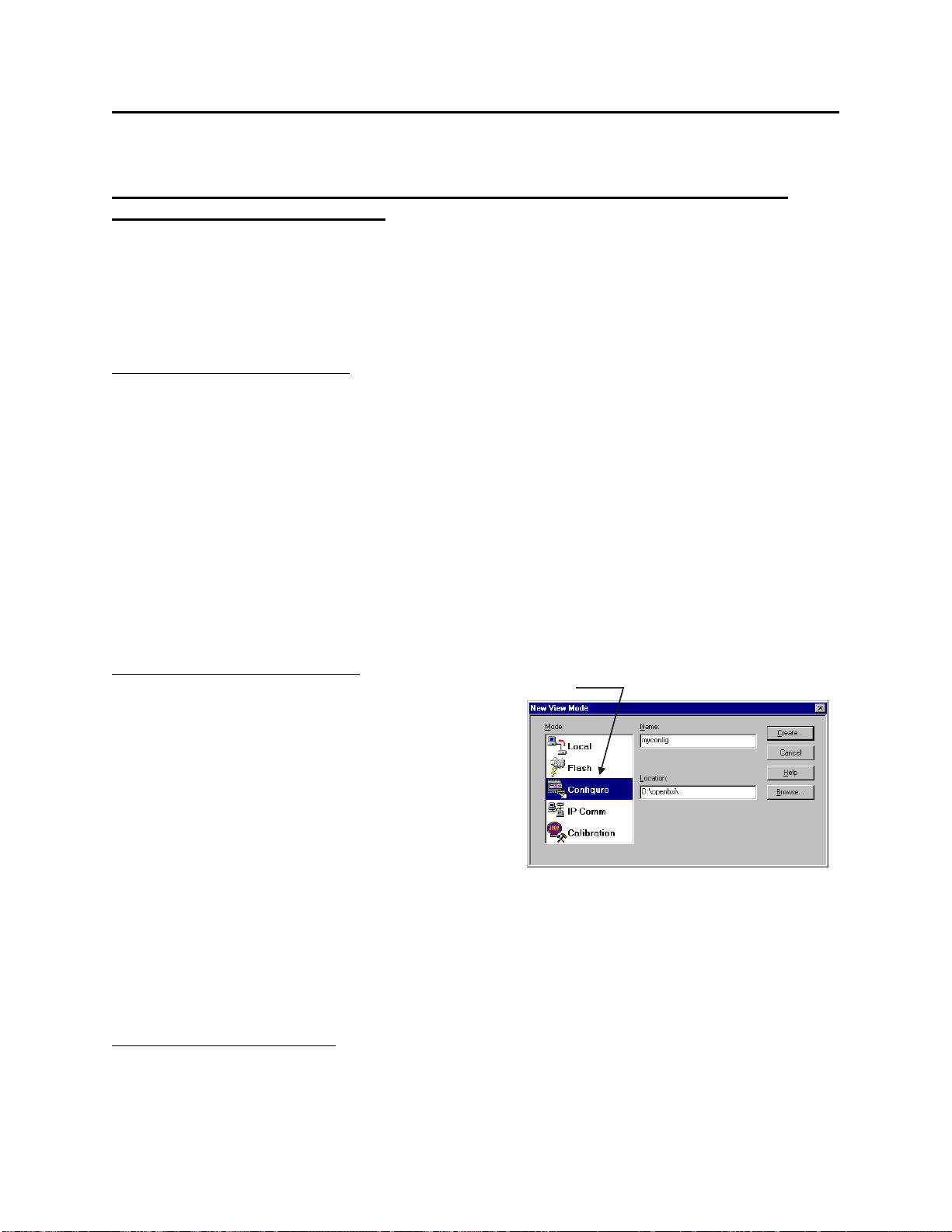
Troubleshooting Redundancy Problems
Variations on Steps 4 and 13 of this Procedure – Saving Flash Configuration
Parameters in the NETDEF File
In the procedure, above, we used the Flash Configuration Profile (FCP) file to save flash
configuration parameters and soft switch settings. Instead, we could have saved this information
in the NETDEF file for this network. This method, however, varies depending upon whether you
are communicating via LocalView or NetView.
If communicating via NetView:
If communicating via NetView, this method is straightforward, since you will already have
chosen a NETDEF file in order to communicate.
In the Flash Configuration Utility, choose [Load From RTU] to call up the flash parameters and
soft switch settings from the on-line ControlWave.
Click on [Close] at the conclusion of the transfer, then click on [Save to NetDef] and all of this
information will be saved in your current NETDEF file.
Later, in Step 13, when configuring the new CPU, choose [Load From NetDef] to call the
information up, instead of [Read Profile].
If communicating via LocalView
If communicating via LocalView, in order to make
use of the actual NETDEF file, you MUST choose
‘Configure Mode’ when starting LocalView.7
If using LocalView to save
data in a NETDEF file, you
MUST choose ‘Configure’
mode.
7
The reason for this is that otherwise, LocalView will use its own temporary NETDEF file which will automatically
disappear on program exit. For full details on using LocalView in ‘Configure Mode’ plea se refer to Chapter 5 of the
Open BSI Utilities Manual (document# D5081).
65
Page 66

Troubleshooting Redundancy Problems
6
C
In addition, when setting up LocalView
communications, you must check the
“Use an existing configuration (.NDF)
file” box, then use the [Browse] button
to locate the NETDEF file containing
this ControlWave controller. Finally,
choose the node name of the controller
from the list box.
The remaining portions of this method are similar to using NetView:
In the Flash Configuration Utility, choose [Load From RTU] to call up the flash parameters and
soft switch settings from the on-line ControlWave. Click on [Close] at the end of the transfer,
then click on [Save to NetDef] and all of this information will be saved in the NETDEF file you
selected.
Later, in Step 13, when configuring the new CPU, choose [Load From File] to call the
information up, instead of [Read Profile].
heck this box, then specify the
NETDEF file which contains this
ControlWave
Specify the node name of the
ControlWave, as specified in
the NETDEF file.
6
Page 67

Troubleshooting Redundancy Problems
7
Correcting Historical Configuration/Data Mismatches
Indication: Standby unit never stays at ‘BA’, it continually cycles through ‘BD’, ‘BC’, ‘BA’ and
back to ‘BD’.
Note: For this procedure, we are assuming “A” is the on-line unit, and “B” is the standby; if
the converse is true, reverse the letters.
Note: The sequence shown here is critical; the steps must be performed in the order shown.
Step # Unit A – Online Unit Unit B – Standby Unit
1.
2.
3.
4.
5.
6.
7.
8.
9.
10.
11.
12.
• Power OFF this unit.
• Power ON this unit.
• Start the Flash Configuration Utility.
• Choose [Load From RTU].
• Power OFF this unit, but leave the Flash
Configuration Utility running.
• Verify that the “B” unit is OFF. (See
Step 10.)
• Power ON the “A” unit.
• Power OFF this unit.
• Power ON this unit (it should now go on-line).
• Start the Flash Configuration Utility (from
within LocalView/NetView).
• On the ‘Archives’ page, remove all of the
archive files.
• On the ‘Audit’ page, set the number of alarms
and events both to 0.
• Then choose [Save to Rtu]. DO NOT save
changes to the NETDEF file.
• Exit the Flash Configuration utility.
• Power OFF this unit.
• Power ON this unit. It should go on-line, with
a clear historical system.
• Choose [Save to Rtu]. This effectively
transfers the historical configuration, but not
the data.
• Power OFF this unit.
• Power ON this unit, it will receive a side-load
of all data from the on-line unit.
• ‘BA’ (without repeated cycles of ‘BD’, ‘BC’)
indicates success.
6
Page 68

BLANK PAGE
Page 69

READER RESPONSE FORM
Please help us make our documentation more useful to you! If you have a complaint, a
suggestion, or a correction regarding this manual, please tell us by mailing this page with your
comments. It's the only way we know we're doing our job by giving you correct, complete, and
useful documentation.
DOCUMENT NUMBER: D5123
TITLE: ControlWave Redundancy Setup Guide
ISSUE DATE: December, 2005
COMMENT/COMPLAINT:
______________________________________________________________________________
______________________________________________________________________________
______________________________________________________________________________
______________________________________________________________________________
______________________________________________________________________________
______________________________________________________________________________
______________________________________________________________________________
______________________________________________________________________________
______________________________________________________________________________
______________________________________________________________________________
______________________________________________________________________________
______________________________________________________________________________
______________________________________________________________________________
FAX this page to (860) 945-2213 or
Mail this page to:
Bristol Babcock Inc.
1100 Buckingham Street
Watertown, CT 06795
Attn: Technical Publications Group, Dept. 610
Page 70

k
U.S.A. Locations:
Northern Region
Bristol Babcock Inc.
1100 Buckingham Street
Watertown, CT 06795
Phone: +1 (860) 945-2381
Fax: +1 (860) 945-2525
NorthernUS@bristolbabcock.com
Helicoid Instruments
1100 Buckingham Street
Watertown, CT 06795
Phone: +1 (860) 945-2218
Fax: +1 (860) 945-2213
jmcgrail@bristolbabcock.com
International
Affiliates:
Canada
Bristol Babcock, Canada
234 Attwell Drive
Toronto, Ont. M9W 5B3
Canada
PH: 416-675-3820
FAX: 416-674-5129
info@bristolbabcock.ca
Calgary Office
Bristol Babcock, Canada
3812 Edmonton Trail N.E.
Calgary, Alberta T2E 5T6
Canada
PH: 403-265-4808
FAX: 403-233-2914
janetl@bristolbabcock.ca
RC Rev: 05-Feb-04
Bristol Babcoc
1100 Buckingham Street
Watertown, CT 06795
Phone: +1 (860) 945-2200
Website: www.bristolbabcock.com
Gulf Coast Region
Bristol Babcock Inc.
2000 Governor's Circle
Suite F
Houston, TX 77092-8731
Phone: +1 (713) 685-6200
Fax: +1 (713) 681-7331
SouthwestUS@bristolbabcock.com
Central Region
Bristol Babcock Inc.
300 North Coit Road
Suite 1300
Richardson, TX 75080
Phone: +1 (972) 238-8935
Fax: +1 (972) 238-8198
dallas@bristolbabcock.com
Mexico
BBI, S.A. de C.V.
Homero No. 1343, 3er Piso
Col. Morales Polanco
11540 Mexico, D.F.
Mexico
PH: (52-55)-52-81-81-12
FAX: (52-55)-52-81-81-09
Mexico@bristolbabcock.com
Villahermosa Office
BBI, S.A. de C.V.
Av. Plomo No.2
Bodega No. 1 - Ciudad
Industrial
Villahermosa, Tabasco 86010
Mexico
PH: 52-993-353-3142
FAX: 52-993-353-3145
bbivsa@prodigy.net.mx
Western Region
Bristol Babcock Inc.
1609 South Grove Avenue
Suites 106 & 107
Ontario, CA 91761
Phone: +1 (909) 923-8488
Fax: +1 (909) 923-8988
WesternUS@bristolbabcock.com
Rocky Mountain Region
Bristol Babcock Inc.
906 San Juan Blvd., Suite A
Farmington, NM 87401
Phone: +1 (505) 320-5046
Fax: +1 (505) 327-3273
NewMexUS@bristolbabcock.com
United Kingdom
Bristol Babcock Ltd.
Blackpole Road
Worcester, WR3 8YB
United Kingdom
PH: +44 (0) 1905 856950
FAX: +44 (0) 1905 856969
enquiries@bristol-babcock.com
Middle East
Bristol Babcock Ltd.
Blackpole Road
Worcester, WR3 8YB
United Kingdom
PH: +44 (0) 1905 856950
FAX: +44 (0) 1905 856969
enquiries@bristol-babcock.com
Fax: +1 (860) 945-2213
Southeast Region
Bristol Babcock Inc.
317 S. North Lake Blvd.
Suite 1016
Altamonte Springs, FL 32701
Phone: +1 (407) 740-7084
Fax: +1 (407) 629-2106
SoutheastUS@bristolbabcock.com
Communications
Technology Group
Bristol Babcock Inc.
317 S. North Lake Blvd.
Suite 1016
Altamonte Springs, FL 32701
Phone: +1 (407) 629-9464
Fax: +1 (407) 629-2106
orlandoRFgroup@bristolbabcock.com
Asia Pacific
Bristol Babcock, Inc.
PO Box 1987
Bunbury, Western Australia
6231
PH: +61 (0) 8 9791 3654
FAX: +61 (0) 8 9791 3173
dtrench@bdsa.com.au
Victoria, Australia
PH: +61 (0) 3 9384 2171
FAX: +61 (0) 3 8660 2501
Page 71

Return to the Table of Contents
Return to the List of Manuals
 Loading...