

Page 1
Instruction Manual
D103412X012
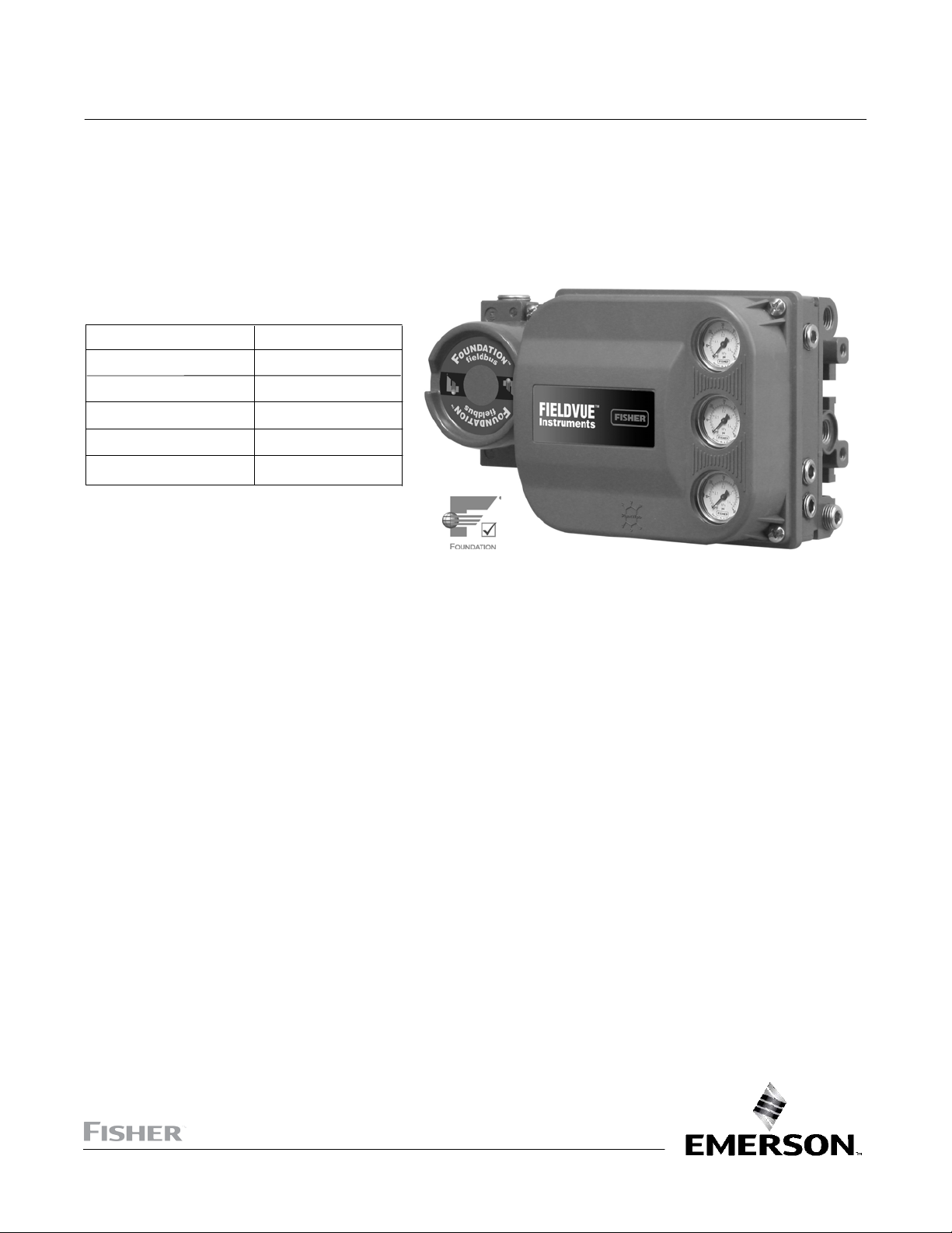
DVC6200f Digital Valve Controller
Fisher™ FIELDVUE™ DVC6200f Digital Valve
May 2022
Controller for F
This manual applies to:
Device Type 4602
Device Revision 4
Hardware Revision 8, 9
Firmware Revision 3.1
DD Revision 3
Instrument Level FD, PD, AD, PST
OUNDATION
™
Fieldbus
www.Fisher.com
1
Page 2

DVC6200f Digital Valve Controller
May 2022
Instruction Manual
D103412X012
2
Page 3

Instruction Manual
D103412X012
DVC6200f Digital Valve Controller
May 2022
Contents
Section 1 Introduction and
Specifications 5......................
Installation, Pneumatic and Electrical Connections,
and Initial Configuration 5.....................
Scope of Manual 5..............................
Instrument Description 5........................
Using this Manual 4.............................
Specifications 8................................
Related Information 12..........................
Educational Services 12..........................
Section 2 Wiring Practices 13.............
Quick Connect Cable Entry 13....................
Communication Connections 14..................
Simulate Enable Jumper 15.......................
Section 3 Basic Setup 17.................
Basic Setup 17.................................
Transducer Block Mode 17......................
Protection 17.................................
Device Setup 18...............................
Performance Tuner 22.........................
Section 4 Detailed Setup 23..............
Resource Block 23..............................
Configure/Setup 23.............................
Resource Block Mode 23.......................
Write Lock 23.................................
Communication Timeout 24....................
Options 24...................................
Alarm Handling 25............................
Identification 26..............................
Version 27...................................
Alert Handling 27.............................
Parameters Affected by Restart with Defaults 28.....
Resoure Block Parameter List 33..................
View Lists 45...................................
Transducer Block 47............................
Detailed Setup 47..............................
Transducer Block Mode 47......................
Protection 47.................................
Response Control 48...........................
Travel Tuning 48...........................
Pressure Tuning 50........................
Travel Pressure Control 51..................
Characterization 53........................
Custom Characterization Table 53............
Output Block Selection 54...................
Alerts 54......................................
Instrument Alert Conditions 54..................
Field Diagnostic Alerts 54.......................
Field Diagnostic Alert Category 55............
Alerts 55.....................................
Electronic Alerts 55........................
Configuration Alerts 57.....................
Sensor Alerts 58...........................
Environment Alerts 59......................
Travel Alerts 60............................
Proximity Alerts 61.........................
Travel History Alerts 62.....................
Performance Alerts 65......................
FST/PST Alerts 65..........................
Alert Handling 67.............................
Instrument 68................................
Valve and Actuator 69..........................
MAI Channel Map 72...........................
FST/PST 72...................................
Latch 78.....................................
Transducer Block Parameter List 79................
View Lists 114..................................
Section 5 Calibration 119................
Calibration Overview 119........................
Calibration 119.................................
Auto 120.....................................
Manual 120..................................
Relay 121....................................
Supply Pressure Sensor 122.....................
Pressure A or B Sensor 123......................
PST Calibration 124............................
Section 6 Viewing Device
Variables and Diagnostics 125..........
View Lists 125..................................
Resource Block 125.............................
Device Diagnostics 125.........................
Device Variables 129...........................
Transducer Block 131...........................
Device Diagnostics 131.........................
Device Variables 134...........................
Section 7 Maintenance and
Troubleshooting 137..................
Replacing the Magnetic Feedback Assembly 138.....
Module Base Maintenance 138....................
Tools Required 138............................
Component Replacement 139...................
Removing the Module Base 139.................
Replacing the Module Base 140..................
Submodule Maintenance 141.....................
I/P Converter 141..............................
Printed Wiring Board (PWB) Assembly 143.........
Pneumatic Relay 144...........................
Gauges, Pipe Plugs or Tire Valves 145.............
Terminal Box 145...............................
Removing the Terminal Box 145.................
Replacing the Terminal Box 146..................
Stroking the Digital Valve Controller Output 146.....
Instrument Troubleshooting 147..................
Technical Support Checklist 152..................
3
Page 4

DVC6200f Digital Valve Controller
May 2022
Instruction Manual
D103412X012
Section 8 Parts 153.....................
Parts Ordering 153..............................
Parts Kits 153..................................
Parts List 154..................................
Housing 154..................................
Common Parts 154............................
Module Base 155..............................
I/P Converter Assembly 155.....................
Relay 155....................................
Terminal Box 155..............................
PWB Assembly 156............................
Pressure Gauges, Pipe Plugs, or
Tire Valve Assemblies 156....................
DVC6215 Feedback Unit 156....................
Appendix A Principle of Operation 163.....
Digital Valve Controller Operation 163.............
Appendix B Device Communicator
Menu Tree 165.......................
Appendix C Field Diagnostic Alerts 183.....
Instrument Alert Conditions 183..................
Field Diagnostic Alerts 183......................
Alert Handling 184............................
Alert Reporting 185............................
Field Diagnostic Alerts Set Block Status 185........
Setting Field Diagnostic Alerts 186................
Using Field Diagnostic Alerts 190..................
Appendix D FOUNDATION Fieldbus
Communication 197..................
Function Block Overview 197.....................
Function Blocks 197...........................
Instrument Specific Blocks 198..................
Resource Blocks 198...........................
Transducer Blocks 198.........................
Block Modes 199...............................
Explanation of Modes 200......................
Examples of Modes for Various
Operation Statuses 201......................
Device Descriptions 201.........................
Transducer Block Status and Limit Propagation 201..
Status Propagation 202........................
Limit Propagation 202..........................
Network Communication 203....................
Device Addressing 203.........................
Link Active Scheduler 203.......................
Device Communications 204....................
Scheduled Transfers 204....................
Unscheduled Transfers 205..................
Function Block Scheduling 206..................
Network Management 206.......................
Appendix E Function Blocks 207...........
Analog Output Function Block 209................
Proportional/Integral/Derivative
Function Block 223...........................
Control Selector Function Block 243...............
Input Selector Function Block 255.................
Output Splitter Function Block 271................
Analog Input Function Block 283..................
Mulitple Analog Input Function Block 295..........
Discrete Output Function Block 301...............
Discrete Input Function Block 315.................
Appendix F Device Description
Installation 327......................
Overview 327..................................
Device Descriptions and Methods 328.............
Installing DD on a DeltaV
ProfessionalPLUS Workstation 328................
Installing DDs on Other Fieldbus Host Systems 330...
Displaying the Device Description Revision 331......
Glossary 333...........................
Index 337.............................
4
Page 5

DVC6200f Digital Valve Controller
Instruction Manual
D103412X012
Introduction and Specifications
Section 1 Introduction and Specifications
Installation, Pneumatic and Electrical Connections,
and Initial Configuration
May 2022
Refer to the DVC6200 Series Quick Start Guide (D103556X012) for DVC6200f
installation, connection, and initial configuration information. If a copy of this quick
start guide is needed contact your Emerson sales office
or visit our website at Fisher.com.
Scan or click
to access
field support
Scope of Manual
This instruction manual is a supplement to the quick start guide that ships with every instrument. This instruction
manual includes product specifications, supplementary installation information, reference materials, custom setup
information, maintenance procedures, and replacement part details for the DVC6200f digital valve controller.
Note
All references to the DVC6200f digital valve controller include the DVC6205f base unit unless otherwise indicated.
This manual describes device setup using an Emerson Device Communicator. For information on using Fisher
ValveLink
™
software with the instrument, refer to the appropriate user guide or help.
Do not install, operate, or maintain a DVC6200f digital valve controller without being fully trained and
qualified in valve, actuator, and accessory installation, operation, and maintenance. To avoid personal
injury or property damage, it is important to carefully read, understand, and follow all of the contents
of this manual, including all safety cautions and warnings. If you have any questions about these
instructions contact your Emerson sales office
before proceeding.
Instrument Description
DVC6200f digital valve controllers for FOUNDATION Fieldbus are communicating, microprocessor‐based instruments. In
addition to the traditional function of converting a digital signal to a pneumatic output pressure, the DVC6200f digital
valve controller, using F
process operation as well as process control. This can be done using a DeltaV console, another F
system console, or with ValveLink software version 13 or later.
Using a compatible fieldbus configuration device, you can obtain information about the health of the instrument, the
actuator, and the valve. You can also obtain asset information about the actuator or valve manufacturer, model, and
serial number. You can set input and output configuration parameters and calibrate the instrument.
Using the F
OUNDATION Fieldbus protocol, information from the instrument can be integrated into control systems.
OUNDATION Fieldbus communications protocol, gives easy access to information critical to
OUNDATION Fieldbus
5
Page 6
DVC6200f Digital Valve Controller
Introduction and Specifications
May 2022
Instruction Manual
D103412X012
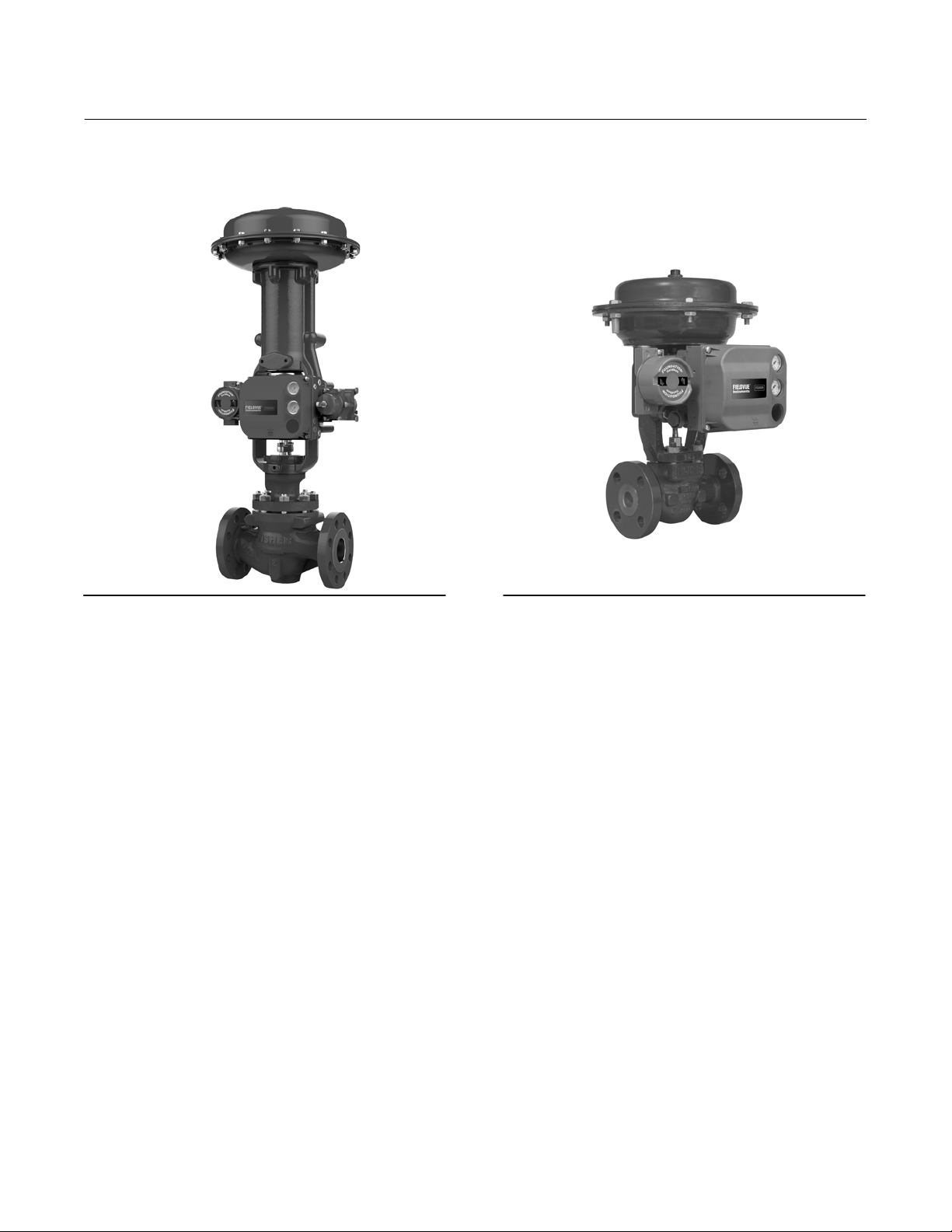
Figure 1‐1 FIELDVUE DVC6200f Digital Valve
Controller Mounted on a Fisher Sliding‐Stem Valve
Actuator
X1182-1_fieldbus
Figure 1‐2. FIELDVUE DVC6200f Digital Valve
Controller Integrally Mounted to a Fisher GX Control
Valve and Actuator System
W9616_fieldbus
DVC6200f digital valve controllers can be mounted on single or double‐acting sliding‐stem actuators, as shown in
figure 1‐1, or on rotary actuators. It can also be integrally mounted to Fisher 657/667 size 30i to 76i actuators or the
Fisher GX control valve and actuator system, as shown in figure 1‐2. The DVC6200f mounts on most Fisher and other
manufacturers' rotary and sliding‐stem actuators.
DVC6200f digital valve controllers are available with several selections of control and diagnostic capability. Control
selections include:
Standard Control (SC)— Digital valve controllers with Standard Control have the AO, PID, CSEL, ISEL, OS, AI, MAI,
DO, and four DI function blocks in addition to the resource and transducer blocks.
Fieldbus Control (FC)—Digital valve controllers with Fieldbus Control have the AO function block in addition to the
resource and transducer blocks.
Fieldbus Logic (FL)—Digital valve controllers with Fieldbus Logic have the DO, and four DI function blocks, in
addition to the resource and transducer block.
The diagnostic capabilities include:
Partial Stroke Test (PST)
Performance Diagnostics (PD)
Advanced Diagnostics (AD)
Fieldbus Diagnostics (FD)
Partial Stroke Test, Performance, and Advanced Diagnostics are available with ValveLink software. They provide
visibility to instrument alerts. Fieldbus Diagnostics can be viewed with any host system.
6
Page 7

DVC6200f Digital Valve Controller
Instruction Manual
D103412X012
Introduction and Specifications
May 2022
Instrument Blocks
The digital valve controller is a block‐based device. For detailed information on the blocks within the digital valve
controller, see the Detailed Setup section of this manual.
The DVC6200f digital valve controller includes the resource and transducer block:
Resource Block—The resource block contains the hardware specific characteristics associated with a device; it has
no input or output parameters. The resource block monitors and controls the general operation of other blocks
within the device. For example, when the mode of the resource block is Out of Service, it impacts all function
blocks.
Transducer Block—The transducer block connects the analog output function block to the I/P converter, relay, and
travel sensor hardware within the digital valve controller.
Function Blocks
In addition to the resource and transducer block, the digital valve controller may contain the following function blocks,
Refer to Appendix E, Function Blocks ,for block specific information. For additional information on function blocks,
refer to Appendix D, F
OUNDATION fieldbus Communication.
Analog Output (AO) Function Block—The analog output function block accepts the output from another function
block (such as a PID block) and transfers it as an actuator control signal to the transducer block. If the DO block is
selected, the AO block is not functional.
Proportional‐Integral‐Derivative (PID) Function Block—The PID function block performs
proportional‐plus‐integral‐plus‐derivative control.
Control Select (CSEL) Function Block— The control select function block selects from two or three control signals in
a manner determined by the SEL_TYPE when the block is in Auto mode.
Input Selector (ISEL) Function Block—The input selector function block selects from up to four inputs and may
provide the selected signal as input to the PID block. The input selection can be configured to select the first good
input signal; a maximum, minimum or average value; or a hot spare.
Output Splitter (OS) Function Block—The output splitter function block accepts the output from another function
block (such as a PID block) and creates two outputs that are scaled or split, according to the user configuration. This
block is typically used for split ranging of two control valves.
Analog Input (AI) Function Block—The analog input function block monitors the signal from a DVC6200f sensor or
internal measurement and provides it to another block.
Multiple Analog Input (MAI) Function Block—The Multiple Analog Input (MAI) function block has the ability to
process up to eight DVC6200f measurements and make them available to other function blocks.
Discrete Output (DO) Function Block—The discrete output function block processes a discrete set point and sends it
to a specified output channel, which can be transferred to the transducer block for actuator control. In the digital
valve controller, the discrete output block provides both normal open/closed control and the ability to position the
valve in 5% increments for course throttling applications. If the AO block is selected, the DO block is not functional.
Discrete Input (DI) Function Block—The discrete input function block processes a single discrete input from a
DVC6200f and makes it available to other function blocks. In the digital valve controller, the discrete input function
block can provide limit switch functionality and valve position proximity detection.
7
Page 8

DVC6200f Digital Valve Controller
Introduction and Specifications
May 2022
Instruction Manual
D103412X012
Using This Manual
Navigation paths and fast‐key sequences are included for procedures and parameters that can be accessed using a
Device Communicator.
For example, to access Resource Block Mode:
Device Communicator RB > Configure/Setup > Setup > Resource Block Mode
An overview of the resource and transducer block menu structures are shown in Appendix B. Menu structures for the
function blocks are included with each function block section in Detailed Setup.
Throughout this document, parameters are typically referred to by their common name or label, followed by the
parameter name and index number; for example, Write Priority (WRITE_PRI [39]). However, not all interface systems
support the use of the parameter label and instead use only the Parameter Name, followed by the index number, when
referring to the block parameters.
Specifications
Specifications for the DVC6200f digital valve controller are shown in table 1‐1.
8
Page 9

Instruction Manual
D103412X012
Table 1‐1. Specifications
DVC6200f Digital Valve Controller
Introduction and Specifications
May 2022
Available Mounting
DVC6200f digital valve controller and DVC6215
feedback unit:
GX actuators
actuators,
Quarter‐turn rotary applications
Integral mounting to 657/667 or
Integral mounting to Fisher rotary
Sliding‐stem linear applications
DVC6205f base unit for 2 inch pipestand or wall
mounting (for remote-mount)
The DVC6200f digital valve controller or DVC6215
feedback unit can also be mounted on other
actuators that comply with IEC 60534-6-1, IEC
60534-6-2, VDI/VDE 3845 and NAMUR mounting
standards.
Instrument Blocks
Resource Block
Transducer Block complies with F
OUNDATION Fieldbus
specification FF-906 for valve stroke testing
Function Block Suites
Standard Control (throttling control)
Includes AO, PID, CSEL, ISEL, OS, AI, MAI, DO,
and DI function block
Fieldbus Control (throttling control)
Contains the AO function block
Fieldbus Logic [discrete (on/off) connectivity]
Includes DO, and DI function blocks
Function Block
Instantiation
If a host system supports block instantiation, a
maximum of 20 function blocks can be instantiated in
the device at any given time from the available
function blocks, which may include AO (1), DO (1), AI
(4), DI (6), MAI (1), PID (4), OS (3), ISEL (2), CSEL (2)
Note: Only the function blocks available in the
function block suite can be instantiated by the host
system
Block Execution Times
Electrical Input
Voltage Level: 9 to 32 volts
Maximum Current: 19 mA
Reverse Polarity Protection: Unit is not polarity
sensitive
Termination: Bus must be properly terminated per
ISA SP50 guidelines
Digital Communication Protocol
F
OUNDATION fieldbus registered device
Physical Layer Type(s):
121—Low-power signaling, bus‐powered,
Entity Model I.S.
511—Low-power signaling, bus‐powered, FISCO I.S.
Fieldbus Device Capabilities
Backup Link Master capable
Supply Pressure
(1)
Minimum Recommended: 0.3 bar (5 psig) higher
than maximum actuator requirements
Maximum: 10.0 bar (145 psig) or maximum pressure
rating of the actuator, whichever is lower
Medium: Air or Natural Gas
Supply medium must be clean, dry and noncorrosive
Per ISA Standard 7.0.01
A maximum 40 micrometer particle size in the air
system is acceptable. Further filtration down to
5 micrometer particle size is recommended.
Lubricant content is not to exceed 1 ppm weight
(w/w) or volume (v/v) basis. Condensation in the air
supply should be minimized.
Per ISO 8573-1
Maximum particle density size: Class 7
Oil content: Class 3
Pressure Dew Point: Class 3 or at least 10C less than
the lowest ambient temperature expected
AO Block: 20 ms MAI BLock: 35 ms
PID Block: 20 ms DO Block: 20 ms
ISEL Block: 20 ms DI Block: 15 ms
OS Block: 20 ms CSEL Block: 15 ms
AI Block: 20 ms
-continued-
Output Signal
Pneumatic signal, up to full supply pressure
Minimum Span: 0.4 bar (6 psig)
Maximum Span: 9.5 bar (140 psig)
Action:
Double, Single Direct or Reverse
9
Page 10

DVC6200f Digital Valve Controller
Introduction and Specifications
May 2022
Table 1‐1. Specifications (continued)
Instruction Manual
D103412X012
Steady-State Air Consumption
(2)(3)
Standard Relay
At 1.4 bar (20 psig) supply pressure:
Less than 0.38 normal m
At 5.5 bar (80 psig) supply pressure:
Less than 1.3 normal m
3
/hr (14 scfh)
3
/hr (49 scfh)
Low Bleed Relay
At 1.4 bar (20 psig) supply pressure:
Average value 0.056 normal m
At 5.5 bar (80 psig) supply pressure:
Average value 0.184 normal m
Maximum Output Capacity
At 1.4 bar (20 psig) supply pressure:
10.0 normal m
At 5.5 bar (80 psig) supply pressure:
29.5 normal m
3
/hr (375 scfh)
3
/hr (1100 scfh)
Operating Ambient Temperature Limits
3
/hr (2.1 scfh)
3
/hr (6.9 scfh)
(2)(3)
(1)(4)
-40 to 85C (-40 to 185F)
-52 to 85C (-62 to 185F) for instruments utilizing
the Extreme Temperature option (fluorosilicone
elastomers)
-52 to 125C (-62 to 257F) for remote‐mount
feedback unit
Independent Linearity
(5)
Typical Value: ±0.50% of output span
Electromagnetic Compatibility
Meets EN 61326-1:2013
Immunity—Industrial locations per Table 2 of
the EN 61326-1 standard. Performance is
shown in table 1‐2 below.
Emissions—Class A
ISM equipment rating: Group 1, Class A
Lightning and Surge Protection—The degree of
immunity to lightning is specified as Surge immunity
in table 1‐2. For additional surge protection
commercially available transient protection devices
can be used.
Vibration Testing Method
Tested per ANSI/ISA‐75.13.01 Section 5.3.5. A
resonant frequency search is performed on all three
axes. The instrument is subjected to the ISA specified
1/2 hour endurance test at each major resonance.
Humidity Testing Method
Tested per IEC 61514-2
Electrical Classification
Hazardous Area Approvals
CSA— Intrinsically Safe, FISCO, Explosion‐proof,
Division 2, Dust Ignition‐proof
FM— Intrinsically Safe, FISCO, Explosion‐proof,
Non‐Incendive, Dust Ignition‐proof
ATEX— Intrinsically Safe, FISCO, Flameproof, Type n,
Dust by intrinsic safety
IECEx— Intrinsically Safe, FISCO, Flameproof, Type n,
Dust by intrinsic safety or by enclosure
Electrical Housing
CSA— Type 4X, IP66
FM— Type 4X, IP66
ATEX— IP66
IECEx— IP66
Other Classifications/Certifications
Natural Gas Certified, Single Seal Device— CSA, FM,
ATEX, and IECEx
Lloyds Register— Marine Type Approval
CCC— China Compulsory Certification
CML— Certification Management Limited (Japan)
CUTR— Customs Union Technical Regulations
(Russia, Kazakhstan, Belarus, and Armenia)
DNV— Marine Type Approval
ESMA— Emirates Authority for Standardization and
Metrology - ECAS-Ex (UAE)
INMETRO— National Institute of Metrology, Quality
and Technology (Brazil)
KOSHA— Korean Occupational Safety & Health
Agency (South Korea)
KTL— Korea Testing Laboratory (South Korea)
NEPSI— National Supervision and Inspection Centre
for Explosion Protection and Safety of
Instrumentation (China)
PESO CCOE— Petroleum and Explosives Safety
Organisation - Chief Controller of Explosives (India)
SANS— South Africa National Standards
Contact your Emerson sales office
for
classification/certification specific information
10
-continued-
Page 11

Instruction Manual
D103412X012
Table 1‐1. Specifications (continued)
DVC6200f Digital Valve Controller
Introduction and Specifications
May 2022
Connections
Supply Pressure: 1/4 NPT internal and integral pad for
mounting 67CFR regulator
Output Pressure: 1/4 NPT internal
Tubing: 3/8‐inch recommended
Optional: Stainless steel
Cover: Thermoplastic polyester
Elastomers
Standard: Nitrile
Extreme Temperature: Fluorosilicone
Vent: 3/8 NPT internal
Electrical: 1/2 NPT internal or M20
Actuator Compatibility
Sliding‐Stem Linear
Linear actuators with rated travel between 6.35 mm
(0.25 inch) and 606 mm (23.375 inches)
Quarter‐Turn Rotary
Rotary actuators with rated travel between
45 degrees and 180 degrees
(6)
Weight
DVC6200f
Aluminum: 3.5 kg (7.7 lbs)
Stainless Steel: 8.6 kg (19 lbs)
DVC6205f: 4.1 kg (9 lbs)
DVC6215: 1.4 kg (3.1 lbs)
Options
Supply and output pressure gauges or Tire
Integral mounted filter regulator
valves
Low‐Bleed Relay
(7)
Extreme Temperature
Natural Gas Certified, Single Seal Device Remote
(8)
Mount
Contact your Emerson sales office
Stainless Steel
or go to Fisher.com
for additional information.
Declaration of SEP
Fisher Controls International LLC declares this
product to be in compliance with Article 4 paragraph
3 of the PED Directive 2014/68/EU. It was designed
and manufactured in accordance with Sound
Engineering Practice (SEP) and cannot bear the CE
marking related to PED compliance.
Construction Materials
Housing, module base and terminal box
Standard: A03600 low copper aluminum alloy
NOTE: Specialized instrument terms are defined in ANSI/ISA Standard 51.1 - Process Instrument Terminology.
1. The pressure/temperature limits in this document and any other applicable code or standard should not be exceeded.
2. Normal m
3. Values at 1.4 bar (20 psig) based on a single-acting direct relay; values at 5.5 bar (80 psig) based on double-acting relay.
4. Temperature limits vary based on hazardous area approval. Lower temperature limit for CUTR Ex d approval with fluorosilicone elastomers is -53C (-63.4F).
5. Not applicable for travels less than 19 mm (0.75 inch) or for shaft rotation less than 60 degrees. Also not applicable for digital valve controllers in long-stroke applications.
6. Rotary actuators with 180 degree rated travel require a special mounting kit; contact your Emerson sales office for kit availability
7. The Quad O steady-state consumption requirement of 6 scfh can be met by a DVC6200f with low bleed relay A option, when used with up to 4.8 bar (70 psi) supply of
Natural Gas at 16C (60F). The 6 scfh requirement can be met by low bleed relay B and C when used with up to 5.2 bar (75 psi) supply of Natural Gas at 16C (60F).
8. 4‐conductor shielded cable, 18 to 22 AWG minimum wire size, in rigid or flexible metal conduit, is required for connection between base unit and feedback unit. Pneumat
ic tubing between base unit output connection and actuator has been tested to 91 meters (300 feet). At 15 meters (50 feet) there was no performance degradation. At
91 meters there was minimal pneumatic lag.
3
/hour - Normal cubic meters per hour at 0C and 1.01325 bar, absolute. Scfh - Standard cubic feet per hour at 60F and 14.7 psia.
However, the product may bear the CE marking to
indicate compliance with other applicable European
Community Directives.
Table 1‐2. EMC Summary Results—Immunity
Port Phenomenon Basic Standard Test Level
Electrostatic discharge (ESD) IEC 61000‐4‐2
Enclosure
I/O signal/control
Performance criteria: +/- 1% effect.
1. A = No degradation during testing. B = Temporary degradation during testing, but is self‐recovering.
2. Excluding Simulate function, which meets Performance Criteria B.
Radiated EM field IEC 61000‐4‐3
Rated power frequency
magnetic field
Burst IEC 61000‐4‐4
Surge IEC 61000‐4‐5
Conducted RF IEC 61000‐4‐6
IEC 61000‐4‐8
4 kV contact
8 kV air
80 to 1000 MHz @ 10V/m with 1 kHz AM at 80%
1400 to 2000 MHz @ 3V/m with 1 kHz AM at 80%
2000 to 2700 MHz @ 1V/m with 1 kHz AM at 80%
30 A/m at 50/60 Hz
1 kV
1 kV
150 kHz to 80 MHz at 3 Vrms
Performance
Criteria
(2)
A
A
A
(2)
A
B
A
(1)
11
Page 12

DVC6200f Digital Valve Controller
Introduction and Specifications
May 2022
Instruction Manual
D103412X012
Related Information
Fieldbus Installation and Wiring Guidelines
This manual describes how to connect the fieldbus to the digital valve controller. For a technical description, planning,
and installation information for F
Fieldbus Foundation and Fieldbus Installations in a DeltaV System, available from your Emerson sales office
Related Documents
Other documents containing information related to the DVC6200f digital valve controller include:
OUNDATION Fieldbus, refer to the Foundation Technology Overview, available from the
.
Bulletin 62.1:DVC6200f - DVC6200f Digital Valve Controller (D103399X012
Bulletin 62.1:DVC6200f FD - DVC6200f Digital Valve Controller (D103422X012
Bulletin 62.1:DVC6200f PST - DVC6200f Digital Valve Controller - PST Instrument Level (D104160X012
Bulletin 62.1:DVC6200(S1) - DVC6200 Digital Valve Controller Dimensions (D103543X012
Bulletin 62.1:Digital Valve Controller - Fisher FIELDVUE Digital Valve Controller Product Selection (D104363X012
FIELDVUE DVC6200 Series Quick Start Guide (D103556X012
CSA Hazardous Area Approvals - DVC6200 Series Digital Valve Controllers (D104203X012
FM Hazardous Area Approvals - DVC6200 Series Digital Valve Controllers (D104204X012
ATEX Hazardous Area Approvals - DVC6200 Series Digital Valve Controllers (D104205X012
IECEx Hazardous Area Approvals - DVC6200 Series Digital Valve Controllers (D104206X012
DVC6200f Digital Valve Controller PST Calibration and Testing using ValveLink Software (D104217X012
™
AMS Trex
ValveLink Software Help or Documentation
Device Communicator User Guide
)
)
)
)
)
)
)
)
)
)
)
All documents are available from your Emerson sales office or at Fisher.com.
Educational Services
For information on available courses for the DVC6200f digital valve controller, as well as a variety of other products,
contact:
Emerson Automation Solutions
Educational Services - Registration
Phone: +1-641-754-3771 or +1-800-338-8158
e‐mail: education@emerson.com
emerson.com/fishervalvetraining
12
Page 13
DVC6200f Digital Valve Controller
Instruction Manual
D103412X012
Installation Information
May 2022
Section 2 Wiring Practices 2-2-
Quick Connect Cable Entry
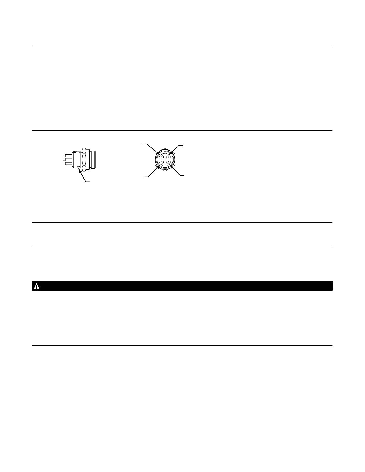
The DVC6200f is offered with a quick connect cable entry option, shown in figure 2‐1, for the FOUNDATION Fieldbus
signal. The quick connect cable entry provides an easier and more reliable interface to fieldbus devices and support
modules by providing a standard connection.
Figure 2‐1. Quick Connect Connector
1 (BLUE)
3 (NC)
2 (BROWN)
1/2‐14 NPT
NOTES:
1. COLORS ARE WIRE COLORS.
2. NC=NO CONNECTION.
18B9424‐A
Note
The quick connect cable entry option is only available for intrinsically safe and non‐incendive installations.
4 (GREEN/YELLOW)
Refer to figure 8‐2 for identification of parts.
WARNING
Personal injury or property damage, caused by fire or explosion, can result from the discharge of static electricity. Connect
a 14 AWG (2.08 mm
gases are present. Refer to national and local codes and standards for grounding requirements.
To avoid static discharge from the plastic cover, do not rub or clean the cover with solvents. Clean with a mild detergent
and water only.
To avoid personal injury or property damage, do not use the Quick Connect option on instruments in explosion‐proof or
flameproof installations.
2
) ground strap between the digital valve controller and earth ground when flammable or hazardous
1. The quick connect cable entry should be installed on the digital valve controller at the factory. If it is, proceed to
step 3. If not continue with step 2.
2. To install the Quick Connect:
a. Remove the terminal box cap (key 4) from the terminal box (key 3).
b. Apply sealant to the threads of the quick connector.
c. Insert the wire pigtail into the desired conduit opening on the terminal box. Tighten the quick connector in the
conduit opening.
13
Page 14

DVC6200f Digital Valve Controller
Installation Information
May 2022
Instruction Manual
D103412X012
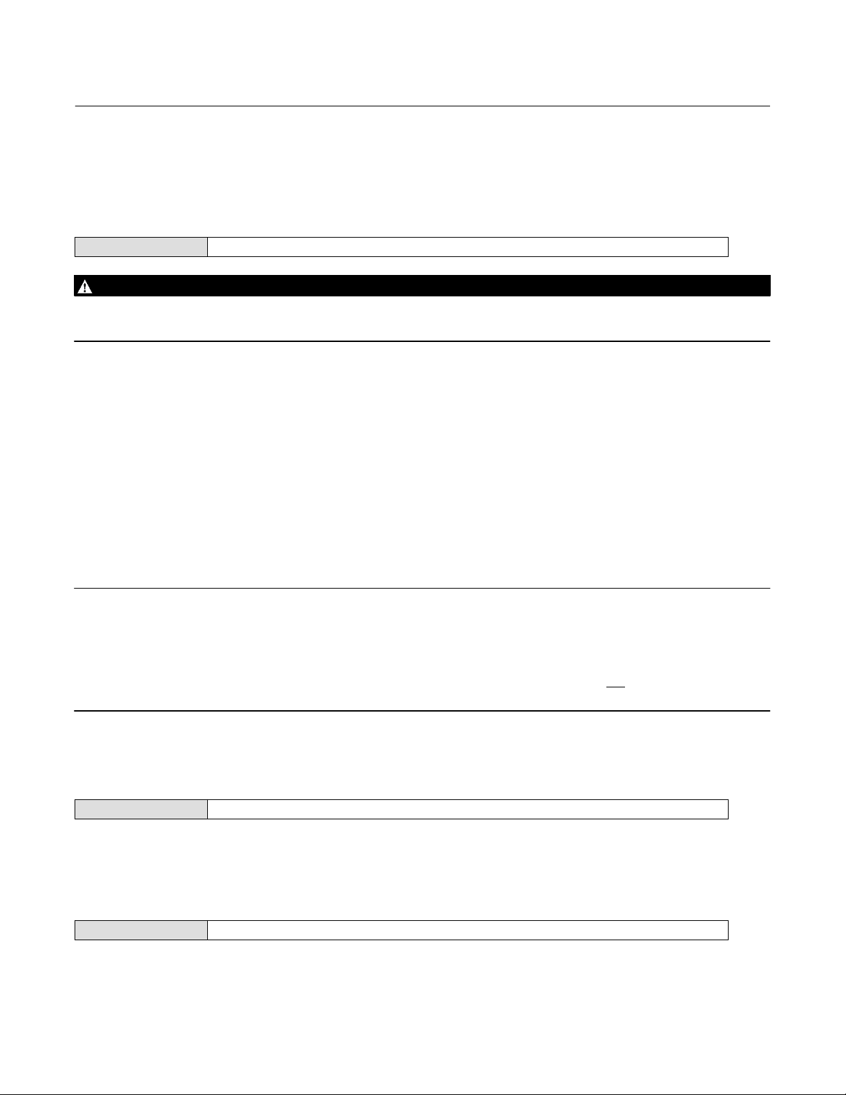
d. The instrument is not polarity sensitive. Refer to figure 2‐2. Connect the blue wire to the negative (-) LOOP
terminals in the terminal box. Connect the brown wire to the positive (+) LOOP terminal. Isolate the green/yellow
wire inside of the DVC6200f and ensure that the shield is totally isolated at the instrument end.
Note
The green/yellow wire is isolated inside the DVC6200f to help prevent ground loop issues.
e. Replace the terminal box cap on the terminal box and tighten until no gap remains. Secure the terminal box cap
by engaging the lock screw.
3. Connect the field wiring connector to the installed quick connector.
Figure 2‐2. Loop Connections Terminal Box
SAFETY
GROUND
GE41456-A
TALK
TALK
EARTH
GROUND
LOOP
LOOP
Communication Connections
WARNING
Personal injury or property damage caused by fire or explosion may occur if this connection is attempted in a potentially
explosive atmosphere or in an area that has been classified as hazardous. Confirm that area classification and atmosphere
conditions permit the safe removal of the terminal box cap before proceeding.
A FOUNDATION Fieldbus communicating device, such as an Emerson Device Communicator or a personal computer
running ValveLink software, interfaces with the DVC6200f digital valve controller from any wiring termination point in
the segment. If you choose to connect the fieldbus communicating device directly to the instrument, attach the
device to the LOCAL connections inside the terminal box to provide local communications with the instrument.
14
Page 15

DVC6200f Digital Valve Controller
Instruction Manual
D103412X012
Installation Information
May 2022
Simulate Enable Jumper
WARNING
Personal injury or property damage caused by fire or explosion may occur if this connection is attempted in a potentially
explosive atmosphere or in an area that has been classified as hazardous. Confirm that area classification and atmosphere
conditions permit the safe removal of the terminal box cap before proceeding.
Install a jumper across the SIMULATE ENABLE terminals to enable the instrument to accept a simulate command.
(These terminals are marked AUX on the terminal board, see figure 2‐2). With the jumper in place and the simulate
parameter in the AO or DO block set to enabled, the transducer block ignores the output of the AO or DO block. The
simulate value and status become the readback value and status to the AO or DO block and the transducer block is
ignored. For more information on running simulations, see the Detailed Setup section of this manual, the
Fieldbus specifications, and the host documentation.
WARNING
Removing the jumper will disable the simulate, which may cause the valve to move. To avoid personal injury and property
damage caused by the release of pressure or process fluid, provide some temporary means of control for the process.
FOUNDATION
15
Page 16

DVC6200f Digital Valve Controller
Installation Information
May 2022
Instruction Manual
D103412X012
16
Page 17
DVC6200f Digital Valve Controller
Instruction Manual
D103412X012
Basic Setup
May 2022
Section 3 Basic Setup3-3-
Basic Setup
Device Communicator TB > Configure/Setup > Basic Setup
WARNING
Changes to the instrument setup may cause changes in the output pressure or valve travel. Depending on the application,
these changes may upset process control, which may result in personal injury or property damage.
When the DVC6200f digital valve controller is ordered as part of a control valve assembly, the factory mounts the
digital valve controller and sets up the instrument as specified on the order. When mounting to a valve in the field, the
instrument needs to be setup to match the instrument to the valve and actuator.
Before beginning basic setup, be sure the instrument is correctly mounted as described in the Installation section.
Basic Setup includes the following procedures:
Device Setup
Performance Tuner (Optional)
Note
The DVC6200f may keep the Transducer Block Mode Out‐of‐Service if the instrument is not properly mounted.
To setup and calibrate the instrument, the Transducer Block Mode must be Manual, and the Protection must be None.
When using DD methods the method will request that you change the mode, but make changes in Protection automatically. If you
have a host system that overrides transducer block parameters ensure that the Protection setting is not
result in transducer block parameters being overwritten.
left as None. Doing so will
Transducer Block Mode
Device Communicator TB > Device Variables > TB Block Mode
To setup and calibrate the instrument, the transducer block mode must be in Manual. For more information about
transducer block mode, refer to page 47.
Protection
Device Communicator TB > Configure/Setup > Detailed Setup > Protection
To setup and calibrate the instrument, the protection must be set to None with the Device Communicator. For more
information about configuration protection refer to page 47.
17
Page 18

DVC6200f Digital Valve Controller
Basic Setup
May 2022
Instruction Manual
D103412X012
Device Setup
Device Communicator TB > Configure/Setup > Basic Setup > Device Setup
Follow the prompts on the Device Communicator display to automatically setup the instrument using specified
actuator information. Table 3‐2 provides the actuator information required to setup and calibrate the instrument.
Note
If reverse‐acting relay B is used, you must manually set the Relay Type (BASIC_SETUP.RELAY_TYPE [42.5]) to B. This will not be set
during Device Setup.
1. Select whether Travel, Travel with Pressure fallback (auto recovery or manual recovery) or Pressure Control is
desired. Refer to page 51 for additional information.
2. Enter the pressure units: kPa, bar, psi, inHg, inH
3. Enter the maximum instrument supply pressure and output pressure range (if required).
4. Enter the manufacturer of the actuator on which the instrument is mounted. If the actuator manufacturer is not
listed, select Other.
5. Enter the actuator model or type. If the actuator model is not listed, select Other.
6. Enter the actuator size.
7. Indicate whether a Volume Booster is being used.
8. Specify if factory defaults should be used for basic setup. If you select YES for factory default, the Device
Communicator sets the setup parameters to the values listed in table 3‐1. If you select NO for the factory defaults,
the setup parameters listed in the table remain at their previous settings.
O, or kg/cm2.
2
Table 3‐1. Factory Default Settings
Setup Parameter
Travel Cutoff Hi
Travel Cutoff Lo
Travel Integral Gain
Travel Calibration Trigger
Travel Integral Enable
Travel Integral Limit Hi
Travel Integral Limit Lo
Travel Integral Deadzone
Pressure Cutoff Hi
Pressure Cutoff Lo
Pressure Integral Deadzone
Pressure Integral Hi Limit
Pressure Integral Lo Limit
Input Characterization
Shutdown Trigger
Shutdown Recovery
Output Block Timeout
STOP Hi Pos
STOP Lo Pos
1. For PST instruments, the PST prohibited configuration will be erased if the instrument is set to factory default
settings. These parameters will need to be re-configured if the PST prohibited configuration is desired.
18
(1)
99.5%
0.5%
9.4 repeats/min
No
On
30%
-30%
0.25%
99.5%
-0.5%
0.25%
50.0%
-50.0%
Linear
All Off
All Auto Recovery
600 sec
98%
2%
Default Setting
Page 19

Instruction Manual
D103412X012
DVC6200f Digital Valve Controller
Basic Setup
May 2022
Table 3‐2. Actuator Information for Initial Setup
Actuator
Manufacturer
Fisher
Baumann
NOTE: Refer to table 4‐9 for feedback connection (magnet assembly) information.
1. X = Expert Tuning. Proportional Gain = 4.2; Velocity Gain = 3.0; Minor Loop Feedback Gain = 18.0
2. Travel Sensor Motion in this instance refers to the motion of the magnet assembly.
3. Values shown are for Relay A and C. Reverse for Relay B.
Actuator Model Actuator Size Actuator Style
25
585C & 585CR
657
667
1051 & 1052
1061
1066SR
2052
3024
GX
Air to Extend
Air to Retract Towards the top of the instrument
Rotary
50
60
68, 80
100, 130
30, 30i
34, 34i, 40, 40i
45, 45i, 50, 50i
46, 46i, 60, 60i, 70,
70i & 80‐100
30, 30i
34, 34i, 40, 40i
45, 45i, 50, 50i
46, 46i, 60, 60i, 70,
70i, 76, 76i & 80‐100
20, 30
33
40
60, 70
30
40
60
68, 80, 100, 130
20
27, 75
1
2
3
30, 30E
34, 34E, 40, 40E
45, 45E
225
750 K
1200 M
16
32
54
10
25
54
Piston Dbl w/ or w/o
Spring. See actuator
instruction manual and
nameplate.
Spring & Diaphragm
Spring & Diaphragm
Spring & Diaphragm
(Window-mount)
Piston Dbl w/o Spring
Piston Sgl w/Spring
Spring & Diaphragm
(Window-mount)
Spring & Diaphragm
Spring & Diaphragm
Spring & Diaphragm
Starting
Tuning Set
E
I
J
L
M
H
K
L
M
H
K
L
M
H
I
K
M
J
K
L
M
G
L
H
K
M
E
H
K
(1)
X
C
E
H
E
H
J
Travel Sensor Motion
Relay A or C
User Specified
Away from the top of the instrument
Towards the top of the instrument
Away from the top of the instrument
Depends upon pneumatic connections. See
description for Travel Sensor Motion
Mounting Style Travel Sensor Motion
A
B
C
D
Away from the top of the instrument
For Po operating mode (air opens):
Towards the top of the instrument
For P
operating mode (air closes):
s
Away from the top of the instrument
Air to Open
Towards the top
of the instrument
Away from the top of the instrument
Away from the top of the
Towards the top of the
Towards the top of the
Away from the top of the
Away from the top of the
Specify
(2)
(3)
instrument
instrument
instrument
instrument
Air to Close
instrument
19
Page 20

DVC6200f Digital Valve Controller
Basic Setup
May 2022
Instruction Manual
D103412X012
Typically Device Setup determines the required setup information based upon the actuator manufacturer and model
specified. However, if you enter OTHER for the actuator manufacturer or the actuator model, then you will be
prompted for setup parameters such as:
Actuator Style—Select spring & diaphragm, piston double‐acting without spring, piston single‐acting with spring,
piston double‐acting with spring.
Valve Style—Select the valve style, rotary or sliding‐stem.
Zero Power Condition—this identifies whether the valve is fully open or fully closed when the input is 0%. If you are
unsure how to set this parameter, disconnect the instrument from the segment. (With double‐acting and
single‐acting direct digital valve controllers, disconnecting the instrument from the segment is the same as setting
the output A pressure to zero. For single‐acting reverse digital valve controllers, disconnecting the instrument from
the segment is the same as setting the output B pressure to supply.)
WARNING
If you answer YES to the prompt for permission to move the valve when setting the Travel Sensor Motion, the instrument
will move the valve through its full travel range. To avoid personal injury and property damage caused by the release of
pressure or process fluid, isolate the valve from the process and equalize pressure on both sides of the valve or bleed off the
process fluid.
Travel Sensor Motion—Device Setup asks if it can move the valve to determine travel sensor motion. If you answer
Yes, the instrument will stroke the valve the full travel span to determine travel sensor motion. If you answer No,
then you must specify the direction of travel movement. For quarter‐turn actuators determine rotation by viewing
the rotation of the magnet assembly from the back of the instrument.
Note
Travel Sensor Motion in this instance refers to the motion of the magnet assembly. Note that the magnet assembly may be
referred to as a magnetic array in user interface tools.
For instruments with relay A or C If increasing air pressure at output A causes the magnet assembly to move up, or
the actuator shaft to rotate counterclockwise, enter “Towards Top of Instrument/CCW.” If it causes the magnet
assembly to move down, or the actuator shaft to rotate clockwise, enter “Away From Top of Instrument/CW.” For
instruments with relay B.
For instruments with relay B If decreasing air pressure at output B causes the magnet assembly to move up, or the
actuator shaft to rotate counterclockwise, enter “Towards Top of Instrument/CCW.” If it causes the magnet
assembly to move down, or the actuator shaft to rotate clockwise, enter “Away From Top of Instrument/CW.”
Note
Relay A adjustment may be required before Device Setup can determine travel sensor motion. Follow the prompts on the Device
Communicator display if relay adjustment is necessary.
Table 3‐2 lists the required Travel Sensor Motion selections for Fisher and Baumann actuators.
20
Page 21

DVC6200f Digital Valve Controller
Instruction Manual
D103412X012
Basic Setup
May 2022
Tuning Set—There are twelve tuning sets to choose from. Each tuning set provides a preselected value for the digital
valve controller gain settings. Tuning set C provides the slowest response and M provides the fastest response. For
smaller actuators use tuning set C or D. For larger actuators using tuning set F or G. Table 3‐3 lists the values for
preselected tuning sets.
Note
Tuning set B is only available in Pressure Control Mode.
Table 3‐3. Gain Values for Preselected Tuning Sets
Travel Pressure
Tuning Set
B
C
D
E
F
G
H
I
J
K
L
M
X (Expert) User Adjusted User Adjusted User Adjusted User Adjusted User Adjusted User Adjusted
Proportional Gain Velocity Gain
‐ ‐ ‐
4.4
4.8
5.5
6.2
7.2
8.4
9.7
11.3
13.1
15.5
18.0
‐ ‐ ‐
3.0
3.0
3.0
3.1
3.6
4.2
4.8
5.6
6.0
6.0
6.0
Minor Loop
Feedback Gain
‐ ‐ ‐
35
35
35
35
34
31
27
23
18
12
12
Proportional Gain Integrator Gain
0.5
2.2
2.4
2.8
3.1
3.6
4.2
4.8
5.6
6.6
7.8
9.0
0.3
0.1
0.1
0.1
0.1
0.1
0.1
0.1
0.1
0.1
0.1
0.1
Minor Loop
Feedback Gain
35
35
35
35
35
34
31
27
23
18
12
12
WARNING
Changes to the tuning set may cause the valve/actuator assembly to stroke. To avoid personal injury or property damage
caused by moving parts, keep hands, tools, and other objects away from the valve/actuator assembly.
In addition, you can select Expert, which allows you to individually set the proportional gain, velocity gain, and minor
loop feedback gain for travel tuning and pressure proportional gain, pressure integrator gain, and pressure minor loop
feedback gain for pressure tuning. Refer to page 48 for additional information on travel tuning and page 50 for
pressure tuning.
Note
Use Expert tuning only if standard tuning has not achieved the desired results.
Stabilize/Optimize or Performance Tuner may be used to achieve the desired results more rapidly than expert tuning.
Table 3‐2 provides tuning set selection guidelines for Fisher and Baumann actuators. These tuning sets are only
recommended starting points. After you finish setting up and calibrating the instrument, use Stabilize/Optimize to
adjust the tuning set to get the desired response.
21
Page 22

DVC6200f Digital Valve Controller
Basic Setup
May 2022
Instruction Manual
D103412X012
When Device Setup is complete you are asked if you wish to run Auto Calibration now. Select yes to automatically
calibrate instrument travel at this time. Follow the prompts on the Device Communicator display. The calibration
procedure uses the valve and actuator stops as the 0% and 100% calibration points. For additional information, refer to
Auto Calibration in the Calibration section.
Note
Single‐acting relay B and C are not user‐adjustable. However, it is recommended that you check the relay adjustment for
double‐acting relay A in new installations before proceeding with travel calibration.
Refer to page 121 for relay adjustment instructions.
If after completing setup and calibration the valve cycles or overshoots (unstable), or is unresponsive (sluggish), you
can improve operation by running Performance Tuner or Stabilize/Optimize.
Performance Tuner
Device Communicator TB > Configure/Setup > Detailed Setup > Response Control > Travel Tuning > Performance Tuner
WARNING
During performance tuning the valve may move, causing process fluid or pressure to be released. To avoid personal injury
and property damage caused by the release of process fluid or pressure, isolate the valve from the process and equalize
pressure on both sides of the valve or bleed off the process fluid.
The Performance Tuner is used to determine digital valve controller tuning. It will move the valve slightly and monitor
the effects of small tuning changes until an optimum control response is achieved. Because the Performance Tuner
can detect internal instabilities before they become apparent in the travel response, it can generally optimize tuning
more effectively than manual tuning. Typically, the Performance Tuner takes 3 to 5 minutes to tune an instrument,
although tuning instruments mounted on larger actuators may take longer.
22
Page 23

DVC6200f Digital Valve Controller
Instruction Manual
D103412X012
Detailed Setup - Resource Block
May 2022
Section 4 Detailed Setup 4-4-
Resource Block
The resource block contains the hardware specific characteristics associated with a device; it has no input or output
parameters. The resource block monitors and controls the general operation of other blocks within the device. Most of
the resource block parameters are operational parameters that provide information about the instrument such as
identification, hardware information, available options, etc. and are read only. Configuration of the resource block
involves selecting features from those that are available, setting the mode, setting write lock, and setting up alert
reporting details.
The following procedures address only the key resource block parameters; however, all resource block parameters are
listed in table 4‐2.
Configure/Setup
Device Communicator RB > Configure/Setup
Resource Block Mode
Modes
The resource block can be in one of two modes (MODE_BLK [5]):
Automatic (Auto) is the operational mode for this block. When the resource block is in the Auto mode, all other
function blocks are allowed to function normally.
Out of Service (OOS)—Placing the resource block in Out of Service mode stops all function block execution, by
setting their modes to Out of Service as well. The actual mode of the function blocks is changed to Out of Service, but
the function block target modes are retained. Placing the resource block in the Out of Service mode does not affect
the mode of the transducer block.
Write Lock
Write Lock (WRITE_LOCK [34]) determines if writes are permissible to other device parameters. The write lock feature
must be selected to be able to use Write Lock (see Features Available). When Write Lock is set to Locked, no writes are
permitted to any parameters within the device except to set Write Lock to Not Locked. When locked, the device
functions normally, updating inputs and outputs and executing algorithms. When Write Lock is set to Not Locked, the
Write Alarm (WRITE_ALM [40]) alert is active.
Write Priority (WRITE_PRI [39]) sets the priority for Write Alarm. The lowest priority is 0. The highest is 15.
23
Page 24

DVC6200f Digital Valve Controller
Detailed Setup - Resource Block
May 2022
Instruction Manual
D103412X012
Communication Timeout
Shed Remote Cascade
Note
Typically this parameter does not need to be changed. The unit will be operational using the default values assigned by the factory.
Perform this procedure only if a remote computer is sending setpoints from your “advanced” control.
Default value for RCas Timeout is 20 seconds.
Shed Remote Cascade (SHED_RCAS [26]) determines how long function blocks in the DVC6200f should wait before
giving up on remote computer writes to RCas parameters. When the timeout is exceeded, the block sheds to the next
mode as defined by the block shed options. If Shed Remote Cascade is set to 0, the block will not shed from RCas.
Enter a positive value in the Shed Remote Cascade field. Time duration is in 1/32 milliseconds (640000
Shed Remote Out
= 20 secs).
Note
Typically this parameter does not need to be changed. The unit will be operational using the default values assigned by the factory.
Perform this procedure only if a remote computer is sending setpoints from your “advanced” control.
Default value for Shed Remote Out is 20 seconds.
Shed Remote Out (SHED_ROUT [27]) determine how long function blocks in the DVC6200f should wait before giving
up on computer writes to ROut parameters. When the timeout is exceeded, the block sheds to the next mode as
defined by the block shed options. If Shed Remote Out is set to 0, the block will not shed from ROut. Enter a positive
value in the Shed Remote Out field. Time duration is in 1/32 milliseconds (640000
= 20 secs).
Options
Diagnostic Tier (DIAG_OPTIONS [103]) show which diagnostic options are available in the instrument.
Function Block Options (FB_OPTIONS [102]) show which function blocks are available in the instrument.
Miscellaneous Options (MISC_OPTIONS [104]) indicate which miscellaneous licensing options are enabled.
Features Available (FEATURES [17]) indicates which feature options are available in the resource block.
Reports enables alert and event reporting. Reporting of specific alerts may be suppressed. See Alerts on page 54.
Fault State enables the ability of the output block to react to various abnormal conditions by shedding mode. See
parameter descriptions for Set Fault State (SET_FSTATE [29]) and Clear Fault State (CLR_FSTATE [30]) in table 4‐2
and “Action on Fault Detection”.
Write Lock permits using Write Lock (WRITE_LOCK [34]) to prevent any external change to parameter values. Block
connections and calculation results will proceed normally, but the configuration is locked. Also see Write Lock, on
page 23.
24
Page 25

DVC6200f Digital Valve Controller
Instruction Manual
D103412X012
Detailed Setup - Resource Block
May 2022
Multi‐bit Alarm (Bit‐Alarm) Support permits the instrument to treat each Field Diagnostic alert separately when
broadcast to the Host. Without Multi‐Bit Alarm Support, an individual Field Diagnostic alert must be acknowledged
before another Field Diagnostic alert can be broadcast to the Host.
Features Selected
Note
Typically this parameter does not need to be changed. The unit will be operational using the default values assigned by the factory.
Fault State, Software Write Lock, and Output Readback are set by default.
Features Selected (FEATURE_SEL [18]) indicates which Resource Block Options features have been selected and is used
to select the desired features.
Reports—Selecting reports enables alert and event reporting. Reporting of specific alerts may be suppressed. See
Alerts on page 54.
Fault State—Selecting fault state enables the ability of the output block to react to various abnormal conditions by
shedding mode. See parameter descriptions for Set Fault State (SET_FSTATE [29]) and Clear Fault State
(CLR_FSTATE [30]) in table 4‐2 and “Action on Fault Detection”.
Soft Write Lock—When selected, permits using Write Lock (WRITE_LOCK [34]) to prevent any external change to
parameter values. Block connections and calculation results will proceed normally, but the configuration is locked.
Also see Write Lock, on page 23.
Multi‐bit Alarm (Bit‐Alarm) Support— When selected, the instrument will allow the instrument to treat each Field
Diagnostic alert separately when broadcast to the Host.
Alarm Handling
Alert Key (ALERT_KEY [4]) is a number that permits grouping alerts. This number may be used to indicate to the
operator the source of the alert, such as the instrument, plant unit, etc. Enter a value between 1 and 255.
Confirm Time (CONFIRM_TIME [33]) determines the time, in 1/32 of a millisecond, the instrument waits for
confirmation of receipt of a report before trying again. If Confirm Time is 0, the instrument does not retry to send the
report. Enter 0 or a value between 320000 (10 secs) and 640000 (20 secs).
Limit Notify (LIM_NOTIFY [32]) is the number of alert reports that the device can send without getting a confirmation
up to the maximum permitted in Maximum Notify (MAX_NOTIFY [31]). If Limit Notify is set to zero, no alerts are
reported. Enter a value between 0 and 4.
To have the instrument report alerts without having the host poll the alerts parameters, select the Reports feature (see
Feature Select).
Maximum Notify (MAX_NOTIFY [31]) indicates the maximum number of alert reports that the device can send without
getting a confirmation. This limit is determined by the amount of memory available for alert messages. The number
can be set lower, to control alert flooding, by adjusting Maximum Alerts Allowed (LIM_NOTIFY [32]).
Block Alarm Disabled The Block Alarm (BLOCK_ALM [36]) is used for all configuration, hardware, connection failure or
system problems in the block. Alarm Summary (ALARM_SUM [37]) determines if the Write Alarm (WRITE_ALM [40])
and Block Alarm [BLOCK_ALM [36]) are disabled.
25
Page 26

DVC6200f Digital Valve Controller
Detailed Setup - Resource Block
May 2022
Block Alarm Auto Acknowledge (ACK_OPTION [38]) determines if the block alarm will be automatically
acknowledged.
Discrete Alarm Disabled The Write Alarm (WRITE_ALM [40]) is used to alert when parameters are writable to the
device. Alarm Summary (ALARM_SUM [37]) determines if the Discrete Alarm is disabled.
Discrete Alarm Auto Acknowledge (ACK_OPTION [38]) determines if the Write Alarm associated with the block will be
automatically acknowledged.
Instruction Manual
D103412X012
Identification
Device ID (DEVICE_ID [110]) is the 32 character Device ID.
Electronics Serial Number (ELECTRONICS_SN [106]) is set at the factory.
Factory Serial Number (FACTORY_SN [107]) is the instrument serial number set at the factory.
Field Serial Number (FIELD_SN [108]) is the serial number of instrument assigned in field.
Tag Description (TAG_DESC [2]) is used to assign a unique 32 character description to each block within the digital
valve controller to describe the intended application for the block.
Strategy (STRATEGY [3]) permits strategic grouping of blocks so the operator can identify where the block is located.
The blocks may be grouped by plant area, plant equipment, etc. Enter a value between 0 and 65535 in the Strategy
field.
Manufacturer (MANUFAC_ID [10]) identifies the manufacturer of the instrument. It is used by the host system to
locate the DD file for the device. For Fisher the Manufacturer ID is 0x5100.
Device Type (DEV_TYPE [11]) identifies the type of device. It is used by the host system to locate the DD file for the
device. For a DVC6200f digital valve controller the device type is 0x4602.
Diagnostic Options (DIAG_OPTIONS [45]) shows the diagnostic options available in the instrument.
26
Page 27

DVC6200f Digital Valve Controller
Instruction Manual
D103412X012
Detailed Setup - Resource Block
May 2022
Version
Device Revision (DEV_REV [12]) is the manufacturer's revision number associated with the resource, used by an
interface device to locate the DD file for the resource.
Firmware Revision (FIRMWARE_REVISION [105]) identifies the revision of the firmware that is currently in use.
Standby Firmware Revision (STBY_FIRMWARE_REVISION [111]) identifies the revision of the alternative firmware.
Hardware Revision (HARDWARE_REVISION [83]) identifies the revision of the electronic hardware.
ITK Version (ITK_VER [41]) identifies the major version of the Interoperability Tester used by the Fieldbus Foundation
in certifying the device as interoperable. This device revision meets the requirements of version 6.
Alert Handling
Simulate Enabled/Disabled (FD_SIMULATE [73]), when enabled, allows the user to write to the following Field
Diagnostic and Instrument alert parameters; Failed Active, Maintenance Active, Offspec Active, and Check Active. This
provides a way to simulate these alerts for testing. In order to enable Field Diagnostic Alerts Simulate, the Aux
Terminal must be jumpered.
Simulate Active Alerts is cleared on a power cycle. It can also be cleared manually, or by removing the Aux terminal
jumper.
Refer to Alerts on page 54 for additional information setting Field Diagnostic and Instrument alerts.
Enable/Disable FD Simulation
All Diag Tiers FD Alerts
PST Diag Tier FD Alerts
27
Page 28

DVC6200f Digital Valve Controller
Detailed Setup - Resource Block
May 2022
Parameters Affected by Restart with Defaults
Instruction Manual
D103412X012
Table 4‐1. Parameters Affected by Restart with
Defaults
Index
Number
1
2
3
4
5 MODE_BLK
14
18
20
26
27
28
32
33
34
37
38
39
1
2
3
4
5
8
9
11 PV_SCALE
12
14
15
17
18
19
20
21
22
Parameter Name Initial Value
Resource Block
ST_REV
TAG_DESC
STRATEGY
ALERT_KEY
TARGET
PERMITTED
NORMAL
GRANT_DENY
FEATURE_SEL
CYCLE_SEL
SHED_RCAS
SHED_ROUT
FAULT_STATE
LIM_NOTIFY
CONFIRM_TIME
WRITE_LOCK
ALARM_SUM_DISABLED
ACK_OPTION
WRITE_PRI
AO Block
ST_REV
TAG_DESC
STRATEGY
ALERT_KEY
MODE_BLK
TARGET
PERMITTED
NORMAL
SP
OUT
EU 100%
EU 0%
Engineering Units
Decimal Places
XD_SCALE
EU 100%
EU 0%
Engineering Units
Decimal Places
IO_OPTS
STATUS_OPTS
CAS_IN
SP_RATE_DN
SP_RATE_UP
SP_HI_LIM
SP_LO_LIM
CHANNEL
-Continued-
0
spaces
0
0
OOS
AUTO or OOS
AUTO
All bits: 0
Set by mfgr.
0:0
640000
640000
1: Clear
MAX_NOTIFY
640000
1: Unlocked
All bits: 0
Disabled
0
0
spaces
0
0
OOS
OOS+MAN+AUTO+CAS+RCAS
CAS+Auto
Dynamic
Dynamic
100
0
%
0
100
0
%
0
All off
All off
BAD
Not Connected
Not Limited
+INF
+INF
100
0
Setpoint
Table 4‐1. Parameters Affected by Restart with
Defaults
Index
Number
23
24
26
27
1
2
3
4
5
8
9
10 PV_SCALE
11
13
14
15
16
17
18
19
20
21
22
23
24
25
26
27
Parameter Name Initial Value
AO Block (continued)
FSTATE_TIME
FSTATE_VAL
RCAS_IN
Status
Value
SHED_OPT
PID Block Parameters
ST_REV
TAG_DESC
STRATEGY
ALERT_KEY
MODE_BLK
TARGET
PERMITTED
NORMAL
SP
OUT
EU 100%
EU 0%
Engineering Units
Decimal Places
OUT_SCALE
EU 100%
EU 0%
Engineering Units
Decimal Places
CONTROL_OPTS
STATUS_OPTS
IN
Status
Value
PV_FTIME
BYPASS
CAS_IN
Status
Value
SP_RATE_DN
SP_RATE_UP
SP_HI_LIM
SP_LO_LIM
GAIN
RESET
BAL_TIME
RATE
BKCAL_IN
Status
Value
-Continued-
0
0
BAD
Not Connected
Not Limited
0 Trk
Uninitialized
0
spaces
0
0
OOS
OOS+MAN+AUTO+CAS+
RCAS+ROUT
AUTO
Dynamic
Dynamic
100
0
%
0
100
0
%
0
0: Bypass enable
All off
BAD
Not Connected
Not Limited
0
0
Uninitialized
BAD
Not Connected
Not Limited
0
+INF
+INF
100
0
1
+INF
0
0
BAD
Not Connected
Not Limited
0
28
Page 29

Instruction Manual
D103412X012
DVC6200f Digital Valve Controller
Detailed Setup - Resource Block
May 2022
Table 4‐1. Parameters Affected by Restart with
Defaults
Index
Number
28
29
30
32
33
34 SHED_OPTS Uninitialized
38
39
40
41
42
45
46
47
48
49
50
51
52
53
54
55
56
57
58
59
66
69
70
71
72
73
74
Parameter Name Initial Value
PID Block (continued)
OUT_HI_LIM
OUT_LO_LIM
BKCAL_HYS
RCAS_IN
Status
Value
ROUT_IN
Status
Value
TRK_IN_D
Status
Value
TRK_VAL
Status
Value
FF_VAL
Status
Value
FF_SCALE
EU 100%
EU 0%
Engineering Units
Decimal Places
FF_GAIN
ALARM_SUM
DISABLED
ACK_OPTION
ALARM_HYS
HI_HI_PRI
HI_HI_LIM
HI_PRI
HI_LIM
LO_PRI
LO_LIM
LO_LO_PRI
LO_LO_LIM
DV_HI_PRI
DV_HI_LIM
DV_LO_PRI
DV_LO_LIM
BIAS
SP_FTIME
MATHFORM
STRUCTURECONFIG
GAMMA
BETA
IDEABAND
-Continued-
100
0
0.5%
BAD
Not Connected
Not Limited
0 Trk
BAD
Not Connected
Not Limited
0 Trk
BAD
Not Connected
Not Limited
0
BAD
Not Connected
Not Limited
0
BAD
Not Connected
Not Limited
0
100
0
%
0
0
All Off
All Off
0.5%
0
Infinity
0
Infinity
0
- Infinity
0
- Infinity
0
+INF
0
-INF
0
Standard
Err on PI_D
1
0
Table 4‐1. Parameters Affected by Restart with
Defaults
Index
Number
1
2
3
4
5 MODE_BLK
8 OUT_RANGE
10
11
12
13
14
15
16
17
18
19
20
22
Parameter Name Initial Value
ISEL Block
ST_REV
TAG_DESC
STRATEGY
ALERT_KEY
TARGET
PERMITTED
NORMAL
EU_100
EU_0
UNITS_INDEX
DECIMAL
STATUS_OPTS
IN_1
Status
Value
IN_2
Status
Value
IN_3
Status
Value
IN_4
Status
Value
DISABLE_1
Status
Value
DISABLE_2
Status
Value
DISABLE_3
Status
Value
DISABLE_4
Status
Value
SELECT_TYPE
MIN_GOOD
OP_SELECT
Status
Value
-Continued-
0
spaces
0
0
OOS
OOS+MAN+AUTO
AUTO
BAD
100
0
%
0
All off
BAD
Not Connected
Constant
0
BAD
Not Connected
Constant
0
BAD
Not Connected
Constant
0
BAD
Not Connected
Constant
0
BAD
Not Connected
Constant
Use
BAD
Not Connected
Constant
Use
BAD
Not Connected
Constant
Use
BAD
Not Connected
Constant
Use
All off
0
BAD
Not Connected
Constant
0
29
Page 30

DVC6200f Digital Valve Controller
Detailed Setup - Resource Block
May 2022
Instruction Manual
D103412X012
Table 4‐1. Parameters Affected by Restart with
Defaults
Index
Number
25
26
27
28
29
30
31
32
33
34
35
36
37
38
39
40
41
42
43
44
50
Parameter Name Initial Value
ISEL Block (continued)
IN_5
Status
Value
IN_6
Status
Value
IN_7
Status
Value
IN_8
Status
Value
DISABLE_5
Status
Value
DISABLE_6
Status
Value
DISABLE_7
Status
Value
DISABLE_8
Status
Value
AVG_USE
ALARM_SUM
DISABLED
ACK_OPTION
ALARM_HYS
HI_HI_PRI
HI_HI_LIM
HI_PRI
HI_LIM
LO_PRI
LO_LIM
LO_LO_PRI
LO_LO_LIM
ALM_SEL
-Continued-
BAD
Not Connected
Constant
0
BAD
Not Connected
Constant
0
BAD
Not Connected
Constant
0
BAD
Not Connected
Constant
0
BAD
Not Connected
Constant
Use
BAD
Not Connected
Constant
Use
BAD
Not Connected
Constant
Use
BAD
Not Connected
Constant
Use
8
All off
All off
0.5%
0
Infinity
0
Infinity
0
-Infinity
0
-Infinity
All off
Table 4‐1. Parameters Affected by Restart with
Defaults
Index
Number
1
2
3
4
5
10
11
13
14
15
16
20
21
22
23
1
2
3
4
5
10
11 OUT_2_RANGE
13
14
19 BKCAL_1_IN
20
21
Parameter Name Initial Value
DI Block
ST_REV
TAG_DESC
STRATEGY
ALERT_KEY
MODE_BLK
TARGET
PERMITTED
NORMAL
XD_STATE
OUT_STATE
IO_OPTS
STATUS_OPTS
CHANNEL
PV_FTIME
ALARM_SUM
DISABLED
ACK_OPTION
DISC_PRI
DISC_LIM
OS Block
ST_REV
TAG_DESC
STRATEGY
ALERT_KEY
MODE_BLK
TARGET
PERMITTED
NORMAL
OUT_1_RANGE
EU_100
EU_0
UNITS_INDEX
DECIMAL
EU_100
EU_0
UNITS_INDEX
DECIMAL
STATUS_OPTS
CAS_IN
Status
Value
Status
Value
BKCAL_2_IN
Status
Value
BAL_TIME
-Continued-
0
spaces
0
0
OOS
OOS+MAN+AUTO
AUTO
0
0
All off
All off
0
0
All off
All off
0
0
0
spaces
0
0
OOS
OOS+AUTO+CAS
AUTO+CAS
100
0
%
0
100
0
%
0
All Off
Bad
Not Connected
Not Limited
0
Bad
Not Connected
Not Limited
0
Bad
Not Connected
Not Limited
0
0 seconds
30
Page 31

Instruction Manual
D103412X012
DVC6200f Digital Valve Controller
Detailed Setup - Resource Block
May 2022
Table 4‐1. Table Parameters Affected by Restart with
Defaults
Index
Number
1
2
3
4
5
10
11
13
14
15
16
17
18
22
23
24
25
26
27
28
29
30
31
32
38
1
2
3
4
5
7
1
2
3
4
5 MODE_BLK
Parameter Name Initial Value
AI Block
ST_REV
TAG_DESC
STRATEGY
ALERT_KEY
MODE_BLK
TARGET
PERMITTED
NORMAL
XD_SCALE
EU_100
EU_0
UNITS_INDEX
DECIMAL
OUT_SCALE
EU_100
EU_0
UNITS_INDEX
DECIMAL
I/O OPTS
STATUS OPTS
CHANNEL
L_TYPE
LOW_CUT
PV_FTIME
ALARM_SUM
DISABLED
ACK_OPTION
ALARM_HYS
HI_HI_PRI
HI_HI_LIM
HI_PRI
HI_LIM
LO_PRI
LO_LIM
LO_LO_PRI
LO_LO_LIM
ALM_SEL
MAI Block
ST_REV
TAG_DESC
STRATEGY
ALERT_KEY
MODE_BLK
TARGET
PERMITTED
NORMAL
CHANNEL
DO Block
ST_REV
TAG_DESC
STRATEGY
ALERT_KEY
TARGET
PERMITTED
NORMAL
-Continued-
0
spaces
0
0
OOS
OOS, MAN, AUTO
AUTO
100
0
%
0
100
0
%
0
All Off
All Off
0
Uninitialized
0
0 Seconds
All Off
All Off
0.5%
0
Infinity
0
Infinity
0
-Infinity
0
-Infinity
All Off
0
spaces
0
0
OOS
OOS, MAN, AUTO
AUTO
MAI Values
0
spaces
0
0
OOS
OOS+MAN+AUTO+CAS+
RCAS
AUTO+CAS
Table 4‐1. Parameters Affected by Restart with
Defaults
Index
Number
11
12
14
15
17
18
19
20
22
23
27
28
1
2
3
4
5
7
8 OUT_SCALE
9
10
11
12
13
14
15
16
17
Parameter Name Initial Value
DO Block (continued)
PV_STATE
XD_STATE
IO_OPTS
STATUS_OPTS
CAS_IN_D
Status
Value
CHANNEL
FSTATE_TIME
FSTATE_VAL_D
RCAS_IN_D
Status
Value
SHED_OPT
SP_RATE_UP
SP_RATE_DN
CSEL Block
ST_REV
TAG_DESC
STRATEGY
ALERT_KEY
MODE_BLK
TARGET
PERMITTED
NORMAL
OUT
Status
EU_100
EU_0
UNITS_INDEX
DECIMAL
GRANT_DENY
STATUS_OPTS
SEL_1
Status
SEL_2
Status
SEL_3
Status
SEL_TYPE
BKCAL_IN
Status
OUT_HI_LIM
OUT_LO_LIM
0
0
All off
All off
BAD
Non Specific
Not Limited
0
Working Setpoint (D)
0 seconds
0
BAD
NoComm with Last Usable
Value
Not Limited
0
Uninitialized
38
3.40 x 10
38
3.40 x 10
0
Spaces
0
0
OOS
AUTO+MAN+OOS
AUTO
Bad
Non Specific
Not Limited
100
0
%
0
All Off
All Off
Bad
Not Connected
Not Limited
Bad
Not Connected
Not Limited
Bad
Not Connected
Not Limited
Uninitialized
Bad
Not Connected
Not Limited
100
0
31
Page 32

DVC6200f Digital Valve Controller
Detailed Setup - Resource Block
May 2022
Table 4‐1. Parameters Affected by Restart with
Defaults
Index
Number
1
2
3
4
5
86 FD_FAIL_MAP_2 Drive Current
87 FD_OFFSPEC_MAP_2 Drive Signal
88 FD_MAINT_MAP_2 Supply Sensor Fail
89 FD_CHECK_MAP_2 Check
90 FD_FAIL_MASK_2 All Off
91 FD_OFFSPEC_MASK_2 All Off
92 FD_MAINT_MASK_2 All Off
93 FD_CHECK_MASK_2 All Off
104 PROTECTION None
Parameter Name Initial Value
Transducer Block
ST_REV
TAG_DESC
STRATEGY
ALERT_KEY
MODE_BLK
TARGET
PERMITTED
NORMAL
0
Spaces
0
0
OOS
OOS, MAN, AUTO
AUTO
Processor Impaired
Travel Sensor
Performance Critical
LCP Communications
Outlet Pressure Sensor
Supply Pressure
Travel Deviation
Movement History
Performance Reduced
Temperature Sensor Fail
Temperature Limit
Travel Limit
Pressure Fallback
Diagnostic in Progress
Latch Active
Instruction Manual
D103412X012
32
Page 33

Instruction Manual
D103412X012
Resource Block Parameter List
Read/Write Capability: RO - Read Only, RW - Read Write
Mode: The block mode(s) required to write to the parameter
Double indentation and shared Index Number indicates sub‐parameter.
Table 4‐2. Resource Block Parameter Definitions
Label
PARAMETER_NAME
Static Revision
ST_REV
Tag Description
TAG_DESC
Strategy
STRATEGY
Alert Key
ALERT_KEY
Block Mode
MODE_BLK
TARGET_MODE 5.1 RW ALL
ACTUAL_MODE 5.2 RO NA
PERMITTED_MODE 5.3 RW ALL
NORMAL_MODE 5.4 RW ALL
Block Error
BLOCK_ERR
Device State
RS_STATE
Index
Number
RO /
Mode Range
RW
1 RO NA 0 to 65535 0
2 RW NA 7 bit ASCII Spaces
3 RW ALL 0 to 65535 0
4 RW ALL 1 to 255 0
5
3: Auto
7: OOS
3: Auto
6: IMAN (only during
initialization
7: OOS
3: Auto
7: OOS
3: Auto
7: OOS
0: Other
1: Configuration Error
3: Simulate Active
5: Device Fault State
Set
6: Need Maintenance
6 RO N/A
7 RO N/A
Soon
9: Memory Failure
10: Lost Static Data
11: Lost NV Data
13: Need
Maintenance Now
14: Power‐up
15: OOS
0: Undefined
1: Start/Restart
2: Initialization
3: On‐line Linking
4: On‐line
5: Standby
6: Failure
-Continued-
Initial
Value
7: OOS
N/A
3: Auto
7: OOS
3: Auto
Dynamic
5: Standby
DVC6200f Digital Valve Controller
Detailed Setup - Resource Block
May 2022
Description
Data Type: Unsigned16
The revision level of the static data. Increments
by one each time a static parameter changes.
The value is reset to 0 whenever a Restart with
Defaults is performed. See Restarting the
Instrument.
Data Type: Octet String
The user description of the intended application
of the block. Null characters are not allowed in
this data type.
Data Type: Unsigned16
Used to identify groupings of blocks. The data is
not checked or processed by the block.
Data Type: Unsigned8
The identification number of the plant unit.
Devices in a loop or plant section can be
assigned with a common alert key to aid the
operator in determining location of alerts.
Data Type: DS‐69
The actual, target, permitted, and normal
modes.
Target: The requested block mode
Actual: The current mode of the block
Permitted: Allowed modes for Target
Normal: Most common mode for Target
Data Type: Bit String
0 = Inactive
1 = Active
Error status associated with hardware or
software for the resource block. When an error is
shown it may be broadcast to the host through
BLOCK_ALM.
Data Type: Unsigned8
State of the function block application state
machine.
33
Page 34

DVC6200f Digital Valve Controller
Detailed Setup - Resource Block
May 2022
Table 4‐2. Resource Block Parameter Definitions (Continued)
Label
PARAMETER_NAME
Test Read Write
TEST_RW
DD Resource
DD_RESOURCE
Manufacturer Id
MANUFAC_ID
Device Type
DEV_TYPE
Device Revision
DEV_REV
DD Revision
DD_REV
Grant Deny
GRANT_DENY
GRANT 14.1 RW ALL
DENY 14.2 RW ALL
Hard Types
HARD_TYPES
Restart
RESTART
Index
Number
RO /
RW
8 ALL 0
9 RO N/A Spaces
10 RO N/A 0x5100
11 RO N/A 0x4602
12 RO N/A
13 RO N/A 1
14
0: Program
1: Tune
2: Alarm
3: Local
4: Operate
5: Service
6: Diagnostic
0: Program Denied
1: Tune Denied
2: Alarm Denied
3: Local Denied
4: Operate Denied
5: Service Denied
6: Diagnostic Denied
0: Scalar Input
15 RO N/A
16 RW ALL
1: Scalar Output
2: Discrete Input
3: Discrete Output
1: Run
2: Restart resource
3: Restart with
defaults
4: Restart processor
11: Restart w/Factory
Default Blocks
-Continued-
Instruction Manual
D103412X012
RangeMode
Initial
Value
Varies with
release
All bits: 0
All bits: 0
0: 1
1: 1
2: 1
3: 1
1: Run
This parameter may be used in interoperability
testing to read and write all standard data types
supported by the Fieldbus Foundation.
Data Type: Visible String
String identifying the VFD tag of the resource
that contains the Device Description for this
resource.
Data Type: Unsigned32
Manufacturer identification number, used by an
interface device or host to locate the DD file for
the resource. All manufacturer identification
numbers are maintained by the Fieldbus
Foundation. A host usually will have a base
directory for DD files. In this directory is a
subdirectory for each manufacturer id. In each
manufacturer id subdirectory is a directory for
each device type made by that manufacturer.
The device type directories contain files named
by combining the device revision for the
particular device type with the revision of the
device description. The manufacturer id for
Fisher is 0x005100.
Data Type: Unsigned16
Manufacturer's model number associated with
the resource, used by an interface device to
locate the DD file for the resource.
Data Type: Unsigned8
Manufacturer's revision number associated with
the resource, used by an interface device to
locate the DD file for the resource.
Data Type: Unsigned8
The minimum revision of the device description
(DD) that can be used with the device revision of
the instrument.
Data Type: DS‐70
Options for controlling access of a host
computer and to block parameters. Parameter
contains two attributes Grant and Deny each
with program, tune, alarm and local
permissions. Clearing a grant permission sets
the corresponding deny permission, 0 = N/A,
1 = granted.
Deny permissions may be cleared through the
Deny attribute but not set, 0 = N/A, 1 = denied.
Data Type: Bit String
0 = Inactive
1 = Active
The types of hardware available as channel
numbers in this resource.
Data Type: Unsigned8
Allows a manual restart to be initiated. For
details see Restarting the Instrument in this
section.
Description
34
Page 35

Instruction Manual
D103412X012
Table 4‐2. Resource Block Parameter Definitions (Continued)
Label
PARAMETER_NAME
Features
FEATURES
Features Selected
FEATURE_SEL
Cycle Type
CYCLE_TYPE
Cycle Selection
CYCLE_SEL
Minimum Cycle Time
MIN_CYCLE_T
Memory Size
MEMORY_SIZE
Nonvolatile Cycle Time
NV_CYCLE_T
Free Space
FREE_SPACE
Free Time
FREE_TIME
Index
Number
RO /
RW
0: Unicode
1: Reports
2: Faultstate
3: Soft W Lock
17 RO ALL
18 RW ALL
19 RO NA
20 RW ALL
21 RO NA 1760
22 RO NA 32
23 RO NA Positive 576,000
24 RO NA
25 RO NA
5: Out Readback
10: Multi-bit Alarm
(Bit-Alarm) Support
11: Restart/Relink
after FB_Action
13:SIF
0: Unicode
1: Reports
2: Faultstate
3: Soft W lock
10: Multi-bit Alarm
(Bit-Alarm) Support
11: Restart/Relink
after FB_Action
13: SIF
0: Scheduled
1: Completion of
block execution
2: Manufacture
Specific
0: Scheduled
1: Completion of
block execution
-Continued-
DVC6200f Digital Valve Controller
Detailed Setup - Resource Block
May 2022
RangeMode
Initial
Value
Bit 0, 1, 2, 3,
5, 10, 11
Bit 0, 1, 2, 3
Bit 0, 1
All bits: 0
Data Type: Bit String
0 = Inactive
1 = Active
Shows the supported resource block options.
Options are turned on and off via
FEATURE_SELECT.
Data Type: Bit String
0 = Inactive
1 = Active
Shows the selected resource block options. For
details see Device Features in this section.
Data Type: Bit String
0 = Inactive
1 = Active
Identifies the block execution methods available
for this resource, may be scheduled, completion
of block execution
Data Type: Bit String
0 = Inactive
1 = Active
Identifies the block execution method selected
for this resource.
Data Type: Unsigned32
Time duration of the shortest cycle interval (in
1/32 millisecond) of which the resource is
capable. In the digital valve controller this value
is fixed at 1760 (55 milliseconds).
Date Type: Unsigned16
Memory, in kilobytes, available for additional
function blocks. Because no additional function
blocks may be added to DVC6200f instruments,
this parameter value is fixed at 32.
Date Type: Unsigned32
This parameter identifies the minimum time
interval (in 1/32 milliseconds) between copies of
NV class data to NV memory. NV memory is
updated only if there has been a change in the
dynamic value. The last value saved in NV
memory will be available for the restart
procedure or a power cycle. A non‐zero value
regulates the frequency of writes, thus
protecting the life span of the device. If the value
is zero, data will never be automatically copied.
Changes made by other than publishing to NV
parameters will be copied to non‐volatile
memory immediately. For DVC6200f
instruments, this parameter value is fixed at
576,000 (18 seconds).
Data Type: Float
Percent of memory available for additional
function blocks (see also MEMORY_SIZE).
Data Type: Float
Percent of block processing time that is free to
process additional blocks.
Description
35
Page 36

DVC6200f Digital Valve Controller
Detailed Setup - Resource Block
May 2022
Table 4‐2. Resource Block Parameter Definitions (Continued)
Label
PARAMETER_NAME
RCAS Timeout
SHED_RCAS
ROUT Timeout
SHED_ROUT
Fault State
FAULT_STATE
Set Fault State
SET_FSTATE
Clear Fault State
CLR_FSTATE
Maximum Notify
MAX_NOTIFY
Limit Notify
LIM_NOTIFY
Confirm Time
CONFIRM_TIME
Index
Number
RO /
RW
26 RW ALL Positive 640000
27 RW ALL Positive 640000
28 RO N/A
29 RW ALL
30 RW ALL
31 RO N/A 4
32 RW ALL 0 to MAX_NOTIFY MAX_NOTIFY
33 RW ALL
1: Clear
2: Active
1: Off
2: Set
1: Off
2: Clear
> 0
Set by FCS
-Continued-
Instruction Manual
D103412X012
RangeMode
Initial
Value
1: Clear
1: Off
1: Off
640000
Date Type: Unsigned32
Time duration (in 1/32 millisecond) at which to
give up on computer writes to function block
RCAS parameters. If this time is exceeded then
the function block will change to a mode other
than RCAS based on the SHED_OPT parameter
setting. Shed from RCAS mode never happens
when SHED_RCAS is set to zero.
Data Type: Unsigned32
Time duration (in 1/32 millisecond) at which to
give up on computer writes to function block
ROUT parameters. If this time is exceeded then
the function block will change to a mode other
than ROUT based on the SHED_OPT parameter
setting. Shed from ROUT mode never happens
when SHED_ROUT is set to zero.
Data Type: Unsigned8
Forces output function blocks that are not Out
of Service to the fault state condition. While this
parameter is active the output function blocks
will go to an actual mode of Local Override (LO)
and will perform their fault state actions (see
Action On Fault Detection for the output blocks
on pages 214 and 306 of this section). This
parameter is used to test the fault state behavior
that normally occurs when there is a
communication problem between devices. This
parameter is changed by the SET_FSTATE and
CLR_FSTATE parameters so long as the feature
Fault State is selected (see Feature Selection
[index number 18] in this table).
Data Type: Unsigned8
Selecting Set changes the parameter
FAULT_STATE to Active. This is essentially a
“write only” parameter as it will always read OFF
because it is defined as momentary. Writing a
value of OFF has no affect. To use this parameter
the feature Fault State must be selected (see
Features Selected on page 25).
Data Type: Unsigned8
Selecting Clear changes the parameter
FAULT_STATE to Clear and clears the output
function blocks of the FAULT_STATE if the field
condition, if any, has cleared. This is essentially a
“write only” parameter as it will always read OFF
because it is defined as momentary. Writing a
value of OFF has no affect. To use this parameter
the feature Fault State must be selected (see
Features Selected on page 25.
Data Type: Unsigned8
The maximum number of alert reports that this
device can send without getting a confirmation.
To control alert flooding, the number can be set
lower by adjusting the LIM_NOTIFY parameter
value.
Data Type: Unsigned8
The number of alert reports that this device can
send without getting a confirmation up to the
maximum permitted in the parameter
MAX_NOTIFY. If set to zero, then no alerts are
reported.
Data Type: Unsigned32
The time (in 1/32 millisecond) the device waits
for confirmation of receipt of an alert report
before trying again.
Description
36
Page 37

Instruction Manual
D103412X012
Table 4‐2. Resource Block Parameter Definitions (Continued)
Label
PARAMETER_NAME
Write Lock
WRITE_LOCK
Update Event
UPDATE_EVT
UNACKNOWLEDGED 35.1 RW ALL
UPDATE_STATE 35.2 RO NA
TIME_STAMP 35.3 RO NA 0
STATIC_REVISION 35.4 RO NA 0
RELATIVE_INDEX 35.5 RO NA 0
Block Alarm
BLOCK_ALM
UNACKNOWLEDGED 36.1 RW ALL
ALARM_STATE 36.2 RO NA
TIME_STAMP 36.3 RO NA Dynamic
SUBCODE 36.4 RO NA Dynamic
VALUE 36.5 RO NA Dynamic
Alarm Summary
ALARM_SUM
CURRENT 37.1 RO NA
UNACKNOWLEDGED 37.2 RO NA See CURRENT Dynamic
UNREPORTED 37.3 RO NA See CURRENT Dynamic
DISABLED 37.4 RW ALL See CURRENT Dynamic
Acknowledge Option
ACK_OPTION
Index
Number
RO /
RW
34 RW ALL
35
36
37
38 RW ALL
RangeMode
1: Unlocked
2: Locked
0: Uninitialized
1: Acknowledged
2: Unacknowledged
0: Uninitialized
1: Reported
2: Not Reported
0: Uninitialized
1: Acknowledged
2: Unacknowledged
0: Uninitialized
1: Clear-reported
2: Clear-not reported
3: Active-reported
4: Active-not reported
0: Discrete alarm
7: Block Alarm
8: Fail Alarm
9: Off Spec Alarm
10: Maintenance
Alarm
11: Check Alarm
0: Discrete Alarm
(Write Lock off)
7: Block Alarm
8: Fail Alarm
9: Off Spec Alarm
10: Maintenance
Alarm
11: Check Alarm
-Continued-
Initial
Value
1: Unlocked
0: Uninitialized
0: Undefined
Dynamic
Dynamic
Dynamic
All bits: 0
DVC6200f Digital Valve Controller
Detailed Setup - Resource Block
May 2022
Description
Data Type: Unsigned8
If set to Locked, no writes from anywhere are
allowed except to clear WRITE_LOCK by entering
Unlocked. Block inputs will continue to be
updated if they are subscribers. The feature Soft
Write Lock must be selected to enable writing to
this parameter (see Device Features in this
section).
Data Type: DS‐73
This alert is generated by any change to the
static data. To support tracking changes in static
parameter values, the blocks static revision
parameter will be incremented each time a
static parameter value is changed. Also, the
blocks static revision parameter may be
incremented if a static parameter is written but
the value is not changed. If the Actual Mode is
not Out of Service and Reports is selected in the
Feature Select parameter, then this parameter
will be sent to the host system providing the
host has set up alert communications. Changes
to static data while the block is Out of Service
will be reported when the block transitions to
another mode.
Data Type: DS‐72
This alarm is generated by a nonzero value in the
Block Error. parameter. This alarm has a fixed
priority of 2. For a BLOCK_ALM to be broadcast
to the host the following conditions must be
met:
The feature Reports must be selected
Alert communication with the host must be
setup
In the ALARM_SUM parameter, the disable bit
for Block Alarm must be clear.
Data Type: DS‐74
0: clear, acknowledged, reported, enabled
Current alert status, unacknowledged states,
unreported states, and disabled states of the
alarms associated with the function block. The
Resource block only has two alarms: Write Alarm
and Block Alarm.
Data Type: Bit String
0: Disable
1: Enable
Selection of whether alarms associated with the
block will be automatically acknowledged.
37
Page 38

DVC6200f Digital Valve Controller
Detailed Setup - Resource Block
May 2022
Table 4‐2. Resource Block Parameter Definitions (Continued)
Label
PARAMETER_NAME
Write Priority
WRITE_PRI
Write Alarm
WRITE_ALM
UNACKNOWLEDGED 40.1 RW ALL
ALARM_STATE 40.2 RO NA
TIME_STAMP 40.3 RO NA Dynamic
SUBCODE 40.4 RO NA Dynamic
VALUE 40.5 RO NA Dynamic
ITK Version
ITK_VER
Not used 42-51 RO
FD_VER
FD_FAIL_ACTIVE
Index
Number
RO /
RW
39 RW ALL 0 to 15 0
40
41 RO N/A *
Extended Parameters
52 RO 1 Data Type: Uint16
53 RO
RangeMode
0: Uninitialized
1: Acknowledged
2: Unacknowledged
0: Uninitialized
1: Clear-reported
2: Clear-not reported
3: Active-reported
4: Active-not reported
0: Check
1: Drive Current
2: Drive Signal
3: Processor Impaired
4: LCP Button Pressed
5: LCP
Communications Lost
6: Travel Sensor Fail
7: Outlet Pressure
Sensor Fail
8: Supply Pressure
Sensor Fail
9: Temperature
Sensor Fail
10: Supply Pressure
11: Temperature Limit
12: Travel Deviation
13: Travel/Setpoint
Limit
14: Movement History
16: Performance
Critical
17: Performance
Reduced
18: Performance Info
19: Latch Active
20: Pressure Fallback
23: PST Pass
24: PST Abnormal
Continued on next
page:
-Continued-
Initial
Value
Dynamic
Dynamic
Instruction Manual
D103412X012
Description
Data Type: Unsigned8
Priority of the alarm generated by setting
WRITE_LOCK to Unlocked.
0 -- Clear associated alert
1 -- Associated alert not sent
2 -- Reserved for alerts that do not require the
attention of a plant operator, e.g. diagnostic
and system alerts
3-7 -- advisory alarms
8-15 -- critical alarms
Data Type: DS‐72
This alarm is generated when Unlocked in the
WRITE_LOCK parameter is set. This alarm has a
priority of WRITE_PRI. For a WRITE_ALM to be
broadcast to the host the following conditions
must be met:
The feature Reports must be selected
Alert communication with the host must be
setup
In the ALARM_SUM parameter, the disable bit
for Write Alarm must be clear.
WRITE_PRI must be greater than 1.
Data Type: Unsigned16
Major version of ITK test this device has been
tested to. *Initial value depends on the revision
of the DVC6200f.
Data Type: Bit String, 4 bytes
Alert is the act of detecting a condition in the
dev device.
0 = Inactive
1 = Active
38
Page 39

Instruction Manual
D103412X012
Table 4‐2. Resource Block Parameter Definitions (Continued)
Label
PARAMETER_NAME
FD_FAIL_ACTIVE
FD_OFFSPEC_ACTIVE
FD_MAINT_ACTIVE
FD_CHECK_ACTIVE
FD_FAIL_MAP
FD_OFFSPEC_MAP
FD_MAINT_MAP
FD_CHECK_MAP
FD_FAIL_MASK
Index
Number
RO /
RW
Continued from
previous page:
25: FST Pass
26: FST Abnormal
53 RO
54 RO *
55 RO *
56 RO *
57 RW
58 RW
59 RW
60 RW
61 RW
27: Diagnostic in
Progress
28: Test Overdue
29: PST Pending
30: Stroke History
Time Exceeded
AUTO
OOS
AUTO
OOS
AUTO
OOS
AUTO
OOS
AUTO
OOS
-Continued-
RangeMode
*
*
*
*
* All Disabled
Initial
Value
description
description
description
Check |
Latch Active
DVC6200f Digital Valve Controller
Detailed Setup - Resource Block
Description
Data Type: Bit String, 4 bytes
Alert is the act of detecting a condition in the
dev device.
0 = Inactive
1 = Active
Data Type: Bit String, 4 bytes
0 = Inactive
1 = Active
*See FD_FAIL_ACTIVE for Range
Data Type: Bit String, 4 bytes
0 = Inactive
1 = Active
*See FD_FAIL_ACTIVE for Range
Data Type: Bit String, 4 bytes
0 = Inactive
1 = Active
*See FD_FAIL_ACTIVE for Range
Data Type: Bit String, 4 bytes
0 = Disable
1 = Enable
*See FD_FAIL_ACTIVE for Range
See
See
See
After Restart w/Defaults:
LCP Communications
| Drive Current
| Processor Impaired
| Travel Sensor
| Performance Critical
Data Type: Bit String, 4 bytes
0 = Disable
1 = Enable
*See FD_FAIL_ACTIVE for Range
After Restart w/Defaults:
Drive Signal
| Outlet Pressure Sensor
| Supply Pressure
| Travel Deviation
| Movement History
| Performance Reduced
Data Type: Bit String, 4 bytes
0 = Disable
1 = Enable
*See FD_FAIL_ACTIVE for Range
After Restart w/Defaults:
Supply Sensor Fail
| Temperature Sensor Fail
| Temperature Limit
| Travel Limit
| Pressure Fallback
| Diagnostic in Progress
Data Type: Bit String, 4 bytes
0 = Disable
1 = Enable
*See FD_FAIL_ACTIVE for Range
Data Type: Bit String, 4 bytes
0 = Disable
1 = Enable
*See FD_FAIL_ACTIVE for Range
May 2022
39
Page 40

DVC6200f Digital Valve Controller
Detailed Setup - Resource Block
May 2022
Table 4‐2. Resource Block Parameter Definitions (Continued)
Label
PARAMETER_NAME
FD_OFFSPEC_MASK
FD_MAINT_MASK
FD_CHECK_MASK
FD_FAIL_ALM
UNACKNOWLEDGED 65.1 RW
ALARM_STATE 65.2 RO
TIME_STAMP 65.3 RO Dynamic
SUB_CODE 65.4 RO Dynamic
VALUE 65.5 RO Dynamic
FD_OFFSPEC_ALM
UNACKNOWLEDGED 66.1 RW
ALARM_STATE 66.2 RO
TIME_STAMP 66.3 RO Dynamic
SUB_CODE 66.4 RO Dynamic
VALUE 66.5 RO Dynamic
FD_MAINT_ALM
UNACKNOWLEDGED 67.1 RW
ALARM_STATE 67.2 RO
TIME_STAMP 67.3 RO Dynamic
SUB_CODE 67.4 RO Dynamic
VALUE 67.5 RO Dynamic
Index
Number
RO /
RW
62 RW
63 RW
64 RW
65 Data Type: DS-87
66
67
AUTO
OOS
AUTO
OOS
AUTO
OOS
AUTO
OOS
AUTO
OOS
AUTO
OOS
RangeMode
* All Disabled
* All Disabled
* All Disabled
0: Uninitialized
1: Acknowledged
2: Unacknowledged
0: Uninitialized
1: Clear - reported
2: Clear - not
reported
3: Active - reported
4: Active - not
reported
0: Uninitialized
1: Acknowledged
2: Unacknowledged
0: Uninitialized
1: Clear - reported
2: Clear - not
reported
3: Active - reported
4: Active - not
reported
0: Uninitialized
1: Acknowledged
2: Unacknowledged
0: Uninitialized
1: Clear - reported
2: Clear - not
reported
3: Active - reported
4: Active - not
reported
-Continued-
Initial
Value
Dynamic
Dynamic
Dynamic
Dynamic
Dynamic
Dynamic
Instruction Manual
D103412X012
Description
Data Type: Bit String, 4 bytes
0 = Disable
1 = Enable
*See FD_FAIL_ACTIVE for Range
Data Type: Bit String, 4 bytes
0 = Disable
1 = Enable
*See FD_FAIL_ACTIVE for Range
Data Type: Bit String, 4 bytes
0 = Disable
1 = Enable
*See FD_FAIL_ACTIVE for Range
Data Type: DS-87
Alarm is the message notifying a host of an Alert
condition.
Data Type: DS-87
Alarm is the message notifying a host of an Alert
condition.
Data Type: DS-87
Alarm is the message notifying a host of an Alert
condition.
40
Page 41

Instruction Manual
D103412X012
Table 4‐2. Resource Block Parameter Definitions (Continued)
Label
PARAMETER_NAME
FD_CHECK_ALM
UNACKNOWLEDGED 68.1 RW
ALARM_STATE 68.2 RO
TIME_STAMP 68.3 RO Dynamic
SUB_CODE 68.4 RO Dynamic
VALUE 68.5 RO Dynamic
FD_FAIL_PRI
FD_OFFSPEC_PRI
FD_MAINT_PRI
FD_CHECK_PRI
FD_SIMULATE
DIAGNOSTIC_SIMULATE_VALUE 73.1 RW ALL *
DIAGNOSTIC_VALUE 73.2 RO *
ENABLE_DISABLE 73.3 RW ALL
FD_RECOMMEN_ACT
FD_EXTENDED_ACTIVE_1
FD_EXTENDED_ACTIVE_2
FD_EXTENDED_ACTIVE_3
FD_EXTENDED_MAP_1
FD_EXTENDED_MAP_2
FD_EXTENDED_MAP_3
CAPABILITY_LEV
Index
Number
RO /
RW
68
AUTO
OOS
69 RW
70 RW
71 RW
72 RW
73
74 RO
75 RO * Dynamic
76 RO * Dynamic
77 RO * Dynamic
78 RW
79 RW
80 RW
81 RO
AUTO
OOS
AUTO
OOS
AUTO
OOS
AUTO
OOS
AUTO
OOS
AUTO
OOS
AUTO
OOS
RangeMode
0: Uninitialized
1: Acknowledged
2: Unacknowledged
0: Uninitialized
1: Clear - reported
2: Clear - not
reported
3: Active - reported
4: Active - not
reported
0-15 0 Data Type: Uint8
0-15 0 Data Type: Uint8
0-15 0 Data Type: Uint8
0-15 0 Data Type: Uint8
0: Uninitialized
1: Simulate Disabled
2: Simulate Enabled
0: Not Initialized
1: No Action Required
2: FD Alert bit 0
3: FD Alert bit 1
...
33: FD Alert bit 31
34: Simulate Active
*
* *
* *
1: SC
2: FC
3: FL
255: Unknown
-Continued-
DVC6200f Digital Valve Controller
Detailed Setup - Resource Block
Initial
Value
Data Type: DS-87Alarm is the message notifying
a host of an Alert condition.
Dynamic
Dynamic
Data Type: DS-89
*See bit definitions in FD_FAIL_ACTIVE for
Range and Initial Value.
Simulate
Disabled
Not Initialized Data Type: Uint16
Data Type: Bit String, 4 bytes
*See TB.INST_ALERTS_ACTIVE.GROUP_1_
ACTIVE for Range
Data Type: Bit String, 4 bytes
*See TB.INST_ALERTS_ACTIVE.GROUP_2_
ACTIVE for Range
Data Type: Bit String, 4 bytes
*See TB.INST_ALERTS_ACTIVE.GROUP_3_
ACTIVE for Range
Data Type: Bit String, 4 bytes
*
See TB.INST_ALERTS_ ENABLE.GROUP_1_
ENABLE for Range and Initial Value
Data Type: Bit String, 4 bytes
See TB.INST_ALERTS_ENABLE.GROUP_
2_ENABLE for Range and Initial Value
Data Type: Bit String, 4 bytes
See TB.INST_ALERTS_ ENABLE.GROUP_3_
ENABLE for Range and Initial Value
Data Type: Uint8
May 2022
Description
41
Page 42

DVC6200f Digital Valve Controller
Detailed Setup - Resource Block
May 2022
Table 4‐2. Resource Block Parameter Definitions (Continued)
Label
PARAMETER_NAME
Compatibility Revision
COMPATIBILITY_REV
Hardware Revision
HARDWARE_REVISION
PD_TAG
HEALTH_INDEX
Failed Priority
FAILED_PRI
Recommended Action
RECOMMENDED_ACTION
Failed Alarm
FAILED_ALM
UNACKNOWLEDGED 88.1 RW
ALARM_STATE 88.2 RO
TIME_STAMP 88.3 RO Dynamic
SUB_CODE 88.4 RO Dynamic
VALUE 88.5 RO Dynamic
Maintenance Alarm
MAINT_ALM
UNACKNOWLEDGED 89.1 RW
ALARM_STATE 89.2 RO
TIME_STAMP 89.3 RO Dynamic
SUB_CODE 89.4 RO Dynamic
VALUE 89.5 RO Dynamic
Advise Alarm
ADVISE_ALM
UNACKNOWLEDGED 90.1 RW
ALARM_STATE 90.2 RO
TIME_STAMP 90.3 RO Dynamic
SUB_CODE 90.4 RO Dynamic
VALUE 90.5 RO Dynamic
Failed Enable
FAILED_ENABLE
Index
Number
RO /
RW
82 RO 4 Data Type: Uint8
83 RO
84 RO Data Type: Visible String, 32 bytes
85 RO Data Type: Uint8
86 RW
87 RO
88
89
90
91 RO * *
AUTO
OOS
AUTO
OOS
AUTO
OOS
AUTO
OOS
RangeMode
0-15 0 Data Type: Uint8
0: Uninitialized
1: Acknowledged
2: Unacknowledged
0: Uninitialized
1: Clear - reported
2: Clear - not reported
3: Active - reported
4: Active-not reported
0: Uninitialized
1: Acknowledged
2: Unacknowledged
0: Uninitialized
1:Clear - reported
2: Clear - not reported
3: Active - reported
4: Active-not reported
0: Uninitialized
1: Acknowledged
2: Unacknowledged
0: Uninitialized
1:Clear - reported
2: Clear - not reported
3: Active - reported
4: Active-not reported
-Continued-
Initial
Value
Dynamic
Dynamic
Dynamic
Dynamic
Dynamic
Dynamic
Instruction Manual
D103412X012
Description
Data Type: Uint8
Describes electronic hardware revision
information.
Data Type: Uint16
Copy of the FD_RECOMMEN_ACT parameter.
See FD_RECOMMEN_ACT for Range and Initial
Value.
Fix for most serious condition.
Data Type: DS-71
Used to report alerts to host system.
Data Type: DS-71
Used to report alerts to host system.
Data Type: DS-71
Used to report alerts to host system.
Data Type: Bit String, 4 bytes
Copy of FD_FAIL_MAP.
*See FD_FAIL_MAP for Range and Initial Value
42
Page 43

Instruction Manual
D103412X012
Table 4‐2. Resource Block Parameter Definitions (Continued)
Label
PARAMETER_NAME
Failed Suppress
FAILED_MASK
Failed Active
FAILED_ACTIVE
Maintenance Priority
MAINT_PRI
Maintenance Enable
MAINT_ENABLE
Maintenance Suppress
MAINT_MASK
Maintenance Active
MAINT_ACTIVE
Advise Priority
ADVISE_PRI
Advise Enable
ADVISE_ENABLE
Advise Suppress
ADVISE_MASK
Advise Active
ADVISE_ACTIVE
Function Block Options
FB_OPTIONS
Index
Number
RO /
RW
92 RO * *
93 RO * *
94 RW
95 RO * *
96 RO * *
97 RO * *
98 RW
99 RO * *
100 RO * *
101 RO * *
102 RO
AUTO
OOS
AUTO
OOS
0: AO
1: DO
2: AI
3: DI
4: PID
5: ISEL
6: OS
7: MAI
8: CSEL
-Continued-
DVC6200f Digital Valve Controller
Detailed Setup - Resource Block
RangeMode
0-15 0 Data Type: Uint8
0-15 0
Initial
Value
Data Type: Bit String, 4 bytes
Copy of FD_FAIL_MASK.
*See FD_FAIL_MASK for Range and Initial Value.
MASK controls whether an alert is reported. If
alert is enabled the alert condition is evaluated
and the ACTIVE parameter is updated to reflect
if alert is active or not. If the bit is set reporting is
suppressed. Default is all bits cleared.
Data Type: Bit String, 4 bytes
Copy of FD_FAIL_ACTIVE.
*See FD_FAIL_ACTIVE for Range and Initial Value
Data Type: Bit String, 4 bytes
Copy of FD_OFFSPEC_MAP.
*See FD_OFFSPEC_MAP for Range and Initial
Value
Data Type: Bit String, 4 bytes
Copy of FD_OFFSPEC_MASK.
*See FD_OFFSPEC_MASK for Range and Initial
Value
MASK controls whether an alert is reported. If
alert is enabled the alert condition is evaluated
and the ACTIVE parameter is updated to reflect
if alert is active or not. If the bit is set reporting is
suppressed. Default is all bits cleared.
Data Type: Bit String, 4 bytes
Copy of FD_OFFSPEC_ACTIVE.
*See FD_OFFSPEC_ACTIVE for Range and Initial
Value
Data Type: Uint8
Data Type: Bit String, 4 bytes
Bit-wise OR of FD_MAINT_MAP and
FD_CHECK_MAP.
*See FD_MAINT_MAP for Range and
FD_MAINT_MAP and FD_CHECK_MAP for Initial
Value.
Data Type: Bit String, 4 bytes
Bit-wise AND of FD_MAINT_MASK and
FD_CHECK_MASK. *See FD_MAINT_MASK and
FD_CHECK_MASK for Range and Initial Value.
MASK controls whether an alert is reported. If
alert is enabled the alert condition is evaluated
and the ACTIVE parameter is updated to reflect
if alert is active or not. If the bit is set reporting is
suppressed. Default is all bits cleared.
Data Type: Bit String, 4 bytes
Bit-wise OR of FD_MAINT_ACTIVE and
FD_CHECK_ACTIVE. *See FD_MAINT_ACTIVE or
FD_CHECK_ACTIVE for Range.
Data Type: Bit String, 4 bytes
0 = disabled
1 = enabled
Indicates which function block licensing options
are enabled. One bit for each block type that is
supported. Unlicensed blocks cannot be
scheduled and the Actual block mode will
remain OOS.
May 2022
Description
43
Page 44

DVC6200f Digital Valve Controller
Detailed Setup - Resource Block
May 2022
Table 4‐2. Resource Block Parameter Definitions (Continued)
Label
PARAMETER_NAME
Diagnostic Options
DIAG_OPTIONS
Miscellaneous Options
MISC_OPTIONS
Firmware Revision
FIRMWARE_REVISION
FIRMWARE_REV_MAJOR 105.1 RO 3
FIRMWARE_REV_MINOR 105.2 RO 1
FIRMWARE_REV_BUILD 105.3 RO
VL_COMPAT_REV 105.4 RO 3
VLM_COMPAT_REV 105.5 RO 3
DD_COMPAT_REV 105.6 RO 3
FIRMWARE_REV_ALL 105.7 RO
Electronics Serial Number
ELECTRONICS_SN
Factory Serial Number
FACTORY_SN
Field Serial Number
FIELD_SN
Time Since Reset
TIME_SINCE_RESET
Device ID
DEVICE ID
STBY_FIRMWARE_REV
STBY_FIRM_REV_MAJOR 111.1 RO *
STBY_FIRM_REV_MINOR 111.2 RO *
STBY_FIRM_REV_BUILD 111.3 RO *
STBY_VL_COMPAT_REV 111.4 RO *
STBY_VLM_COMPAT_REV 111.5 RO *
STBY_DD_COMPAT_REV 111.6 RO *
STBY_FIRMWARE_REV_ALL 111.7 RO NA XX.XX.XX NA
FB_SUPPORTED
IO_FIRMWARE_REV
Index
Number
RO /
RW
103 RO
104 RO
105
106 RO NA Factory Set
107 RO NA spaces
108 RW
109 RO NA 0
110 RO NA Device ID
111
112 RO
113 RO Data Type: Uint8
AUTO
OOS
RangeMode
1: FD
2: AD
3: PD
4: SIS
5: PST
0x81: FD (temporarily
PD)
0x82: AD (temporarily
PD)
0:Firmware Download
10: Travel Control
11: Pressure Control
12: Fallback Capable
Any String spaces
0: AO
1: DO
2: AI
3: DI
4: PID
5: ISEL
6: OS
7: MAI
8: CSEL
Initial
Value
*
Instruction Manual
D103412X012
Description
Data Type: Uint8
Indicates which diagnostics licensing options are
enabled. *Initial value depends on the licensed
DVC6200f options.
Data Type: Bit String, 4 bytes
Indicates which miscellaneous licensing options
are enabled.
Data Type: Uint8
Describes software revision information. This is
the revision of the firmware that is currently in
use.
Data Type: Visible String
Describes software revision information.
Data Type: Visible String
Electronics serial number set by manufacturing.
Data Type: Visible String
Instrument serial number set by manufacturing.
Data Type: Visible String
Instrument serial number set in the field.
Data Type: Uint32
Number of seconds since the last time
DVC6200f was restarted. Restart due to power
up or restart command.
Data Type: Visible String
Unique 32 character ID used to identify the
device.
Data Type: Uint8
Describes firmware revision information. This is
the revision of the alternative firmware.
*Initial value depends on revision of firmware in
standby.
Data Type: Visible String
Describes firmware revision information.
*Initial value depends on revision of firmware in
standby. The range of this parameter consists of
55.1 through 55.5 values, converted to text, and
linked together.
Data Type: Bit String, 4 bytes
44
Page 45

DVC6200f Digital Valve Controller
Instruction Manual
D103412X012
Detailed Setup - Resource Block
May 2022
View Lists
View lists allow the values of a set of parameters to be accessed at the same time. Views 1 and 2 contain operating
parameters and are defined by the Fieldbus Foundation. View 3 contains dynamic parameters and View 4 contains
static parameters with configuration and maintenance information. Views 3 and 4 are defined by the manufacturer.
Note
Because individual views are limited in size, View List 4 has multiple parts.
Table 4‐3. Resource Block, View Lists
Index Number Parameter
1 ST_REV x x x x x
3 STRATEGY x
4 ALERT_KEY x
5 MODE_BLK x x
6 BLOCK_ERR x x
7 RS_STATE x x
10 MANUFAC_iD x
11 DEV_TYPE x
12 DEV_REV x
13 DD_REV x
14 GRANT_DENY x
15 HARD_TYPES x
17 FEATURES x
18 FEATURE_SEL x
19 CYCLE_TYPE x
20 CYCLE_SEL x
21 MIN_CYCLE_T x
22 MEMORY_SIZE x
23 NV_CYCLE_T x
24 FREE_SPACE x
25 FREE_TIME x x
26 SHED_RCAS x
27 SHED_ROUT x
28 FAULT_STATE x x
31 MAX_NOTIFY x
32 LIM_NOTIFY x
33 CONFIRM_TIME x
34 WRITE_LOCK x
37 ALARM_SUM x x
38 ACK_OPTION x
39 WRITE_PRI x
41 ITK_VER x
52 FD_VER x
53 FD_FAIL_ACTIVE x x
1 2 3 4 4.1
View
45
Page 46

DVC6200f Digital Valve Controller
Detailed Setup - Resource Block
May 2022
Table 4‐3. Resource Block, View Lists (continued)
Index Number Parameter
54 FD_OFFSPEC_ACTIVE x x
55 FD_MAINT_ACTIVE x x
56 FD_CHECK_ACTIVE x x
57 FD_FAIL_MAP x
58 FD_OFFSPEC_MAP x
59 FD_MAINT_MAP x
60 FD_CHECK_MAP x
61 FD_FAIL_MASK x
62 FD_OFFSPEC_MASK x
63 FD_MAINT_MASK x
64 FD_CHECK_MASK x
69 FD_FAIL_PRI x
70 FD_OFFSPEC_PRI x
71 FD_MAINT_PRI x
72 FD_CHECK_PRI x
73 FD_SIMULATE x
74 FD_RECOMMEN_ACT x x
75 FD_EXTENDED_ACTIVE_1 x x
76 FD_EXTENDED_ACTIVE_2 x x
77 FD_EXTENDED_ACTIVE_3 x x
78 FD_EXTENDED_MAP_1 x
79 FD_EXTENDED_MAP_2 x
80 FD_EXTENDED_MAP_3 x
85 HEALTH_INDEX x
86 FAILED_PRI x
87 RECOMMENDED_ACTION x
91 FAILED_ENABLE x
92 FAILED_MASK x
93 FAILED_ACTIVE x
94 MAINT_PRI x
95 MAINT_ENABLE x
96 MAINT_MASK x
97 MAINT_ACTIVE x
98 ADVISE_PRI x
99 ADVISE_ENABLE x
100 ADVISE_MASK x
101 ADVISE_ACTIVE x
102 FB_OPTIONS x
103 DIAG_OPTIONS x
108 FIELD_SN x
109 TIME_SINCE_RESET x
Instruction Manual
D103412X012
View
1 2 3 4 4.1
46
Page 47

DVC6200f Digital Valve Controller
Instruction Manual
D103412X012
Detailed Setup - Transducer Block
May 2022
Transducer Block
The transducer block accepts a signal from an output block as a set point to position a valve using a pneumatic
actuator. Input to the transducer block is in percent. Closed is 0%, and open is 100%. The transducer block contains
setup and calibration information and can be tuned to closely match the actuator. Input characterization permits
modifying the overall characteristic of the instrument‐actuator‐valve combination in order to modify the installed gain
characteristic of the loop. The transducer block can also be used to perform instrument and valve diagnostics and
trigger performance alerts.
The following procedures address only the key transducer block parameters; however, all transducer block parameters
are listed in table 4‐11.
Detailed Setup
Note
To setup and calibrate the instrument, the transducer block Mode must be Manual and the Protection must be None.
Transducer Block Mode
Device Communicator TB > Detailed Setup > Transducer Block Mode
Modes
The transducer block can be in one of four modes (MODE_BLK [5]):
Automatic (Auto)— This is the normal mode for this block. When the transducer block is in the auto mode, it accepts
the output from the AO or DO block as a set point and outputs a drive signal to the I/P converter based upon this set
point.
Out of Service (OOS)— Placing the transducer block in Out of Service mode changes the output to the zero power (no
I/P drive) condition.
Manual (MAN)— Placing the transducer block in Manual will hold the value at the current setpoint (FINAL_VALUE [13]).
The transducer block will not accept changes from the AO or DO blocks. This mode is required to change some
parameters and to run some diagnostics.
Local Override (LO)— The instrument will take the transducer block to a local override mode when a latch is active.
Protection
Device Communicator TB > Configure/Setup > Detailed Setup > Protection
To configure any parameters in the digital valve controller Write Lock (WRITE_LOCK [34]), in the resource block, must
be set to Unlocked (refer to page 23). In addition, protection is provided for various transducer block parameters, as
indicated in the Protect Category column of table 4‐11, to prevent inadvertently overwriting key data by the host
system or user.
None will not protect any transducer block parameters.
47
Page 48

DVC6200f Digital Valve Controller
Detailed Setup - Transducer Block
May 2022
Instruction Manual
D103412X012
Calibration will protect only Calibration transducer block parameters.
Setup and Calibration will protect only Setup and Calibration transducer block parameters.
All— will protect all transducer block Parameters.
Note
The Device Setup Auto Travel and Manual Travel methods automatically change transducer block protection for the user.
See table 4‐11 for individual parameter details.
Response Control
Device Communicator TB > Configure/Setup > Detailed Setup > Response Control
Travel Tuning
WARNING
Changes to the tuning set may cause the valve/actuator assembly to stroke. To avoid personal injury or property damage
caused by moving parts, keep hands, tools, and other objects away from the valve/actuator assembly.
Travel Tuning Set (TVL_TUNING_SET [67.10])
There are eleven travel tuning sets to choose from. Each tuning set provides a preselected value for the digital valve
controller gain settings.
Tuning set C provides the slowest response and M provides the fastest response. Table 4‐4 lists the proportional gain,
velocity gain and minor loop feedback gain values for preselected tuning sets.
In addition, you can specify Expert tuning and individually set the proportional gain, velocity gain, and minor loop
feedback gain. Individually setting or changing any tuning parameter or running the Performance Tuner or
Stabilize/Optimize will automatically change the tuning set to X (expert).
Table 4‐4. Gain Values for Preselected Travel Tuning Sets
Tuning Set Travel Proportional Gain Travel Velocity Gain Travel Minor Loop Feedback Gain
C
D
E
F
G
H
I
J
K
L
M
X (Expert) User Adjusted User Adjusted User Adjusted
4.4
4.8
5.5
6.2
7.2
8.4
9.7
11.3
13.1
15.5
18.0
3.0
3.0
3.0
3.1
3.6
4.2
4.8
5.6
6.0
6.0
6.0
35
35
35
35
34
31
27
23
18
12
12
48
Page 49

DVC6200f Digital Valve Controller
Instruction Manual
D103412X012
Note
Use Expert tuning if standard tuning has not achieved the desired results.
Stabilize/Optimize may be used to achieve the desired results more rapidly than manually editing the Expert tuning.
Detailed Setup - Transducer Block
May 2022
Table 3‐2 provides tuning set selection guidelines for Fisher and Baumann actuators. These tuning sets are
recommended starting points. After you finish setting up and calibrating the instrument, you may have to select either
a higher or lower tuning set to get the desired response.
For an actuator not listed in table 3‐2, you can estimate a starting tuning set by calculating the casing or cylinder
volume. Then, find an actuator in table 3‐2 with the closest equivalent volume and use the tuning set suggested for
that actuator.
Travel Proportional Gain (TVL_PROP_GAIN [72.6]) is the proportional gain for the travel control tuning set. Changing
this parameter will also change the tuning set to Expert.
Travel Velocity Gain (TVL_RATE [72.7]) is the velocity gain for the travel control tuning set. Changing this parameter
will also change the tuning set to Expert.
Travel MLFB Gain (TVL_MLFB_GAIN [72.5]) is the minor loop feedback gain for the travel control tuning set. Changing
this parameter will also change the tuning set to Expert.
Travel Integral Enable (TVL_INTEG_ENABLE [72.1]) is used to enable the integral setting to improve static performance
by correcting for error that exists between the travel target and actual travel.
Travel Integral Gain (TVL_RESET [72.8]) (also called reset) is the ratio of the change in output to the change in input,
based on the control action in which the output is proportional to the time integral of the input.
Travel Integral Dead Zone (TVL_INTEG_DEADZ [72.4]) is a window around the Primary Setpoint in which the integral
action is disabled. The dead zone is configurable from 0 to 2% corresponding to a symmetric window from 0% to +/-2%
around the Primary Setpoint. This dead zone value is used during the Auto Calibration of Travel procedure even if the
travel integral is disabled; in the case of Auto Calibration travel failures with piston actuators, this value should be set
to 1%. Default value is 0.26%.
Travel Integral Limit Hi (TVL_INTEG_LIM_HI [72.2]) provides an upper limit to the integrator output. The high limit is
configurable from 0 to 100% of the I/P drive signal.
Travel Integral Limit Lo (TVL_INTEG_LIM_LO [72.3]) provides a lower limit to the integrator output. The low limit is
configurable from -100 to 0% of the I/P drive signal.
Performance Tuner
WARNING
During performance tuning the valve will move,which may cause process fluid or pressure to be released. To avoid
personal injury and property damage caused by the release of process fluid or pressure, isolate the valve from the process
and equalize pressure on both sides of the valve or bleed off the process fluid.
Performance Tuner is used to determine digital valve controller tuning. It will move the valve slightly and monitor the
effects of small tuning changes until an optimum control response is achieved. Because the Performance Tuner can
detect internal instabilities before they become apparent in the travel response, it can generally optimize tuning more
effectively than manual tuning.
49
Page 50

DVC6200f Digital Valve Controller
Detailed Setup - Transducer Block
May 2022
Instruction Manual
D103412X012
Stabilize/Optimize
WARNING
During Stabilize/Optimize the valve may move, causing process fluid or pressure to be released. To avoid personal injury
and property damage caused by the release of process fluid or pressure, isolate the valve from the process and equalize
pressure on both sides of the valve or bleed off the process fluid.
If after completing initial setup and calibration the valve cycles or overshoots, or is sluggish, you can improve
operation by running Stabilize/Optimize.
Stabilize/Optimize is included with the device description (DD) firmware. Stabilize/Optimize is accessible from the
transducer block and permits changing the transducer block set point a small amount to see if the valve is unstable or
unresponsive. If valve response is unsatisfactory, the method permits adjusting the digital valve controller tuning to
improve response.
If the valve is unstable, select Decrease Response to stabilize valve operation. This selects the next lower tuning set
(e.g., F to E). If the valve response is sluggish, select Increase Response to make the valve more responsive. This selects
the next higher tuning set (e.g., F to G).
If after selecting Decrease Response or Increase Response the valve travel overshoot is excessive, Increase Damping or
Decrease Damping can be used to select a damping value not represented in a predefined tuning set. Select Decrease
Damping to select a damping value that allows more overshoot. Select Increase Damping to select a damping value that
will decrease the overshoot.
When valve operation is satisfactory, select Exit. Before exiting, you are asked if you want to return the transducer
block mode to Auto. Select Yes to change the transducer block mode to Auto. Select No to leave the transducer block
in its current mode.
Pressure Tuning
WARNING
Changes to the tuning set may cause the valve/actuator assembly to stroke. To avoid personal injury or property damage
caused by moving parts, keep hands, tools, and other objects away from the valve/actuator assembly.
Pressure Tuning Set (PRESS_TUNING_SET [67.11])
There are twelve pressure tuning sets to choose from. Each tuning set provides a preselected value for the digital valve
controller gain settings.
Tuning set C provides the slowest response and M provides the fastest response. Tuning set B is appropriate for
controlling a pneumatic positioner. Table 4‐5 lists the proportional gain, pressure integrator gain and minor loop
feedback gain values for preselected tuning sets.
In addition, you can specify Expert tuning and individually set the pressure proportional gain, pressure integrator gain,
and pressure minor loop feedback gain. Individually setting or changing any tuning parameter will automatically
change the tuning set to X (expert).
50
Page 51

DVC6200f Digital Valve Controller
Instruction Manual
D103412X012
Detailed Setup - Transducer Block
Table 4‐5. Gain Values for Preselected Pressure Tuning Sets
Tuning Set Pressure Proportional Gain Pressure Integrator Gain Pressure Minor Loop Feedback Gain
B
C
D
E
F
G
H
I
J
K
L
M
X (Expert) User Adjusted User Adjusted User Adjusted
Note
Use Expert tuning only if standard tuning has not achieved the desired results.
Stabilize/Optimize may be used to achieve the desired results more rapidly than Expert tuning.
0.5
2.2
2.4
2.8
3.1
3.6
4.2
4.8
5.6
6.6
7.8
9.0
0.3
0.1
0.1
0.1
0.1
0.1
0.1
0.1
0.1
0.1
0.1
0.1
35
35
35
35
35
34
31
27
23
18
12
12
May 2022
Pressure Proportional Gain (PRESS_PROP_GAIN [74.3]) is the proportional gain for the pressure control tuning set.
Changing this parameter will also change the tuning set to Expert.
Pressure MLFB Gain (PRESS_MLFB_GAIN [74.11]) is the minor loop feedback gain for the pressure control tuning set.
Changing this parameter will also change the tuning set to Expert.
Pressure Integral Gain (PRESS_INTEG_GAIN [74.4]) (also called reset) is the ratio of the change in output to the change
in input, based on the control action in which the output is proportional to the time integral of the input. This feature is
used during pressure control for greater accuracy during pressure control/fallback. Changing this parameter will also
change the tuning set to Expert.
Pressure Integral Dead Zone (PRESS_INTEG_DEADZ [74.6]) is a window around the Primary Setpoint in which the
integral action is disabled. The dead band is configurable from 0 to 2%.
Pressure Integral Limit Hi (PRESS_INTEG_HI_LIM [74.7]) provides an upper limit to the integrator output. The high
limit is configurable from 0 to 100% of the I/P drive signal.
Pressure Integral Limit Lo (PRESS_INTEG_LO_LIM [74.8]) provides a lower limit to the integrator output. The low limit
is configurable from -100 to 0% of the I/P drive signal.
Travel/Pressure Control
Travel/Pressure State (TVL_PRESS.STATE [65.2]) indicates if the instrument is being used for travel control (position
control) or as an I/P (pressure control)
Travel/Pressure Select (TVL_PRESS_SELECT [65.1])
Note
When using Pressure Fallback Manual Recovery or Pressure Fallback Auto Recovery, the valve travel has the potential of moving
rapidly causing potential process instability when returning to Travel Control.
51
Page 52

DVC6200f Digital Valve Controller
Detailed Setup - Transducer Block
May 2022
Note
Travel / Pressure Select must be set to Travel for double acting actuators.
Instruction Manual
D103412X012
Travel / Pressure Select determines if the instrument is setup for position or pressure control. Select Travel, Pressure,
Travel with Pressure Fallback/Auto recovery or Travel with Pressure Fallback/Manual Recovery. If the travel sensor fails,
and Travel with Pressure Fallback/Auto Recovery is selected, it will return to travel control when the travel sensor starts
working again. Travel with Pressure Fallback/Manual recovery will stay in pressure control until Travel Pressure Select is
changed to Travel or Travel with Pressure Fallback/Auto recovery. It is not necessary to enable the Travel Sensor Alert
for Pressure Fallback to occur.
Travel Deviation Pressure Fallback occurs when the instrument detects that the travel sensor is outside of its normal
range of operation or that a gross deviation exists between set point and actual travel. It switches to Pressure Control
and no longer uses the travel sensor to position the valve.
Pressure Range Hi (PRESS_RANGE_HI [67.7]) is the high end of output pressure range. Enter the pressure that
corresponds with 100% valve travel when Zero Power Condition is closed, or 0% valve travel when Zero Power
Condition is open. This pressure must be greater than the Pressure Range Lo.
Pressure Range Lo (PRESS_RANGE_LO [67.8]) is the low end of the output pressure range. Enter the pressure that
corresponds to 0% valve travel when Zero Power Condition is closed, or 100% valve travel when Zero Power Condition
is open. The pressure must be less than the Pressure Range Hi.
Travel Deviation/Pressure Fallback
Deviation Fallback Enabled (DEV_FALLBK_ENABLE [66.1]) enables the fallback behavior.
Deviation Fallback Threshold (DEV_FALLBK_THRESHOLD [66.2]) If the travel deviation exceeds this threshold for
more than the defined Fallback Time then the instrument falls back to pressure control.
Deviation Fallback Time (DEV_FALLBK_TIME [66.2]) defines the amount of time the travel deviation must exceed
the Fallback Threshold before the instrument falls back to pressure control.
Deviation Fallback Minimum Supply Pressure (DEV_FALLBK_MIN_SUPPLY [66.4]) defines the minimum supply
pressure required for the instrument to fall back to pressure control.
Cutoff
Travel Cutoff Hi (FINAL_VALUE_CUTOFF_HI [16]) defines the high cutoff point for the travel in percent (%) of
pre‐characterized setpoint. Above this cutoff, the travel target is set to 123.0% of the ranged travel. Travel Cutoff Hi
is deactivated by setting it to 125.0%.
Travel Cutoff Lo (FINAL_VALUE_CUTOFF_LO [17]) defines the low cutoff point for the travel in percent (%) of
pre‐characterized setpoint. Below this cutoff, the travel target is set to -23%. A Travel Cutoff Lo of 0.5% is
recommended to help ensure maximum shutoff seat loading. Travel Cutoff Lo is deactivated by setting it to -25.0%
Pressure Cutoff Hi (PRESS_CUTOFF_HI [74.1]) defines the high cutoff point for the pressure in percent (%) of
pre‐characterized setpoint. Above this cutoff, the pressure target is set to 123.0%. A Pressure Cutoff Open of 99.5%
is recommended to ensure valve goes fully open. Pressure Cutoff Hi is deactivated by setting it 125%.
Pressure Cutoff Lo (PRESS_CUTOFF_LO [74.2]) defines the low cutoff point for the pressure in percent (%) of
pre‐characterized setpoint. Below this cutoff, the pressure target is set to -23%. A Pressure Cutoff Closed of 0.5% is
recommended to help ensure maximum shutoff seat loading. Pressure Cutoff Closed is deactivated by setting it to
-25.0%
52
Page 53

DVC6200f Digital Valve Controller
Instruction Manual
D103412X012
Detailed Setup - Transducer Block
May 2022
Characterization
Characterization (INPUT_CHAR [76]) defines the relationship between the travel target and the setpoint received from
the output block. Travel target is the output from the characterization function.
You can select from the three fixed input characteristics shown in figure 4‐1 or you can select a custom characteristic.
Figure 4‐1 shows the relationship between the travel target and travel set point for the fixed input characteristics.
Custom Characterization Table
You can specify 21 points on a custom characteristic curve. Each point defines a travel target, in % of ranged travel, for
a corresponding set point, in % of ranged set point. Set point values range from -25.0% to 125%. Before modification,
the custom characteristic is linear. You cannot modify
Figure 4‐1. Travel Target Versus Ranged Set Point, for Various Input Characteristics (Zero Power Condition = Closed)
the custom points if the Input Characterization is set to custom.
125
100
Travel Target, %
0
-25
-25 0 125100
Set Point, %
Input Characteristic Linear
125
100
125
100
Travel Target, %
0
-25
-25 0 125100
Set Point, %
Input Characteristic Equal Percentage
A6535‐1
Travel Target, %
0
-25
-25 0 125100
Set Point, %
Input Characteristic Quick Opening
53
Page 54

DVC6200f Digital Valve Controller
Detailed Setup - Transducer Block
May 2022
Instruction Manual
D103412X012
Output Block Selection
Output Block Selection (OUTBLOCK_SEL [112]) defines which output function block (AO or DO) will control the
setpoint of the valve. The output block that is not
the valve.
selected will shed its mode to reflect that it does not have control of
Alerts
The DVC6200f provides two levels of alerts; Instrument alerts and Field Diagnostic alerts or PlantWeb alerts. PlantWeb
alerts will be presented to hosts that do not support Field Diagnostic alerts.
Instrument Alert Conditions
Instrument Alert Conditions, when enabled, detect many operational and performance issues that may be of interest.
To view these alerts, open the appropriate status screen on a host such as DeltaV or ValveLink software.
Field Diagnostic Alerts
Some instrument alert conditions can also be used to trigger Field Diagnostic alerts. Field Diagnostic alerts will be
reported in Failed, Function Check, Out of Specification, or Maintenance Required categories, as configured by the
user. When a Field Diagnostic alert occurs, the DVC6200f sends an event notification and waits a specified period of
time for an acknowledgment to be received. This occurs even if the condition that caused the alert no longer exists. If
the acknowledgment is not received within the pre‐specified time‐out period, the event notification is retransmitted.
This reduces the possibility of alert messages being lost.
Field Diagnostic alerts will be mapped to PlantWeb alerts (PWA) as shown below for older DeltaV systems that do not
support Field Diagnostics.
Field Diagnostic Alerts
Failed Failed
Offspec Maintenance
Maintenance
Check
Field Diagnostic alerts are mode‐based. Refer to table C‐1 for details.
Note
Additional details on setting up and using Field Diagnostic Alerts can be found in Appendix C of this manual.
PlantWeb Alerts
Advisory
54
Page 55

DVC6200f Digital Valve Controller
Instruction Manual
D103412X012
Detailed Setup - Transducer Block
May 2022
Field Diagnostic (FD) Alert Category
Select either Enable or Suppress in the desired category for each of the alerts in Electronic, Configuration, Sensor,
Environment, Travel, Proximity, Travel History, Test Overdue, Performance, and Valve Stroke:
Fail Enable (FD_FAIL_MAP_2 [86]) enables or disables conditions that can cause a failed alert. A failed alert indicates a
failure within the device that will make the device or some part of the device non‐operational. Table C‐2 lists the
available Field Diagnostic alerts.
Fail Suppress (FD_FAIL_MASK_2 [90]) determines which of the failed alert conditions are suppressed so that they are
not reported. Even if reporting is suppressed, the bit in Fail Active (FD_FAIL_ACTIVE [RB 53]) is still set in the Resource
Block.
Check Function Enable (FD_CHECK_MAP_2 [89]) enables or disables conditions that can cause a check function alert.
A check function alert indicates that the output signal is temporarily invalid (e.g. frozen) due to ongoing work on the
device.
Check Function Suppress (FD_CHECK_MASK_2 [93]) determines which of the check function alert conditions are
suppressed. Even if the reporting is suppressed, the bit in Check Function Active (FD_CHECK_ACTIVE [RB 56]) is still set
in the Resource Block.
Off Specification Enable (FD_OFFSPEC_MAP_2 [87]) enables or disables conditions that can cause an off specification
alert. An off specification alert indicates that the device is operating outside its specified range or internal diagnostics
indicate deviations from set values. Table C‐2 lists the available Field Diagnostic alerts.
Off Specification Suppress (FD_OFFSPEC_MASK_2 [91]) determines which of the off specification alert conditions are
suppressed so that they are not reported. Even if reporting is suppressed, the bit in Off Specification Active
(FD_OFFSPEC_ACTIVE [RB 54]) is still set in the Resource Block.
Maintenance Enable (FD_MAINT_MAP_2 [88]) enables or disables conditions that can cause a maintenance alert. A
maintenance alert indicates the device or some part of the device needs maintenance soon. Table C‐2 lists the
available Field Diagnostic alerts.
Maintenance Suppress (FD_MAINT_MASK_2 [92]) determines which of the maintenance alert conditions are
suppressed so that they are not reported. Even if reporting is suppressed, the bit in Maintenance Active
(FD_MAINT_ACTIVE [RB 55]) is still set in the Resource Block.
Alerts
Device Communicator TB > Configure/Setup > Detailed Setup > Alerts
The following alerts can be enabled/disabled per plant requirements. Select enable within the specific alert menu to
enable any of the following alerts, or disable to turn off any enabled alert.
Electronic Alerts
Drive Current
Drive Current (DRIVE_CURRENT [79]) displays the measured Drive Current actually flowing through the I/P
converter in percent of maximum drive.
The Drive Current Alert is active when the drive current to the I/P converter is not flowing as expected.
55
Page 56

DVC6200f Digital Valve Controller
Detailed Setup - Transducer Block
May 2022
Instruction Manual
D103412X012
Drive Current Shutdown—The Shutdown Trigger (SHUTDOWN_TRIGGER [83.1]) permits enabling or disabling Self
Test Shutdown for the Drive Current alert. When enabled, and the alert condition is present, the transducer Actual
mode is placed Out of Service. The instrument will attempt to drive the valve to the Zero Power Condition and will
no longer execute transducer control function.
Drive Current Manual Recovery—Shutdown Recovery (SHUTDOWN_RECOVERY [83.2]) permits enabling or
disabling Automatic recovery from Self Test Shutdown. When enabled, the transducer block will return to Target
mode when Drive Current Shutdown clears. If not enabled, the transducer block will remain Out of Service until
power is removed and restored or the user changes the transducer block target mode to Manual or Auto. In any
case, the target mode will remain Out of Service, if the condition that caused the shutdown remains or until the
shutdown trigger is disabled.
Drive Current Alert Point (DRIVE_CURRENT_ALRT_PT [83.4]) is when the absolute difference between the Drive
Current and Drive Signal exceeds the set threshold for greater than the Drive Current Alert Time.
Drive Current Alert Time (DRIVE_CURRENT_TIME [83.5]) is the maximum time that the Drive Current Alert Point can
be exceeded before the Drive Current Alert is active.
Drive Current FD Config
Drive Signal
Drive Signal (DRIVE_SIGNAL [78]) displays the commanded Drive Signal being sent to the I/P converter as a
percentage of the maximum drive.
The Drive Signal Alert is active if one of the following conditions exist:
Where Zero Power Condition is defined as closed:
Drive Signal < 10% and Calibrated Travel > 3%
Drive Signal > 90% and Calibrated Travel < 97%
Where Zero Power Condition is defined as open:
Drive Signal < 10% and Calibrated Travel < 97%
Drive Signal > 90% and Calibrated Travel > 3%
Drive Signal FD Config
Processor Impaired
The Program Memory Alert is active if a pending Flash or NVM failure is present.
Program Memory Shutdown—The Shutdown Trigger (SHUTDOWN_TRIGGER [83.1]) permits enabling or disabling
Self Test Shutdown. When enabled, and the Program Memory Alert is active, the transducer Actual mode is placed
out of service. The instrument will attempt to drive the valve to the zero power condition and will no longer execute
transducer control function.
Program Memory Manual Recovery—Shutdown Recovery (SHUTDOWN_RECOVERY [83.2]) permits enabling or
disabling Automatic recovery from Self Test Shutdown. When enabled, the transducer block will return to Target
mode when the condition that caused Program Memory Shutdown clears. If not enabled, the transducer block will
remain Out of Service until power is removed and restored or the user changes the transducer block target mode to
56
Page 57

DVC6200f Digital Valve Controller
Instruction Manual
D103412X012
Detailed Setup - Transducer Block
May 2022
Manual or Auto. In any case, the target mode will remain Out of Service, if the condition that caused the shutdown
remains or until the shutdown trigger is disabled.
The Static Memory Alert is active if a failure occurs in the FRAM memory where the static parameters are stored.
Static Memory Shutdown—The Shutdown Trigger (SHUTDOWN_TRIGGER [83.1]) permits enabling or disabling Self
Test Shutdown. When enabled, and the Static Memory Alert is active, the transducer Actual mode is placed out of
service. The instrument will attempt to drive the valve to the zero power condition and will no longer execute
transducer control function.
Static Memory Manual Recovery—Shutdown Recovery (SHUTDOWN_RECOVERY [83.2]) permits enabling or
disabling Automatic recovery from Self Test Shutdown. When enabled, the transducer block will return to Target
mode when the condition that caused Static Memory Shutdown clears. If not enabled, the transducer block will
remain Out of Service until power is removed and restored or the user changes the transducer block target mode to
Manual or Auto. In any case, the target mode will remain Out of Service, if the condition that caused the shutdown
remains or until the shutdown trigger is disabled.
The I/O Processor Alert is active if a failure occurs in the I/O processor.
I/O Processor Shutdown—The Shutdown Trigger (SHUTDOWN_TRIGGER [83.1]) permits enabling or disabling Self
Test Shutdown. When enabled, and the I/O Processor Alert is active, the transducer Actual mode is placed out of
service. The instrument will attempt to drive the valve to the zero power condition and will no longer execute
transducer control function.
I/O Processor Manual Recovery—Shutdown Recovery (SHUTDOWN_RECOVERY [83.2]) permits enabling or
disabling Automatic recovery from Self Test Shutdown. When enabled, the transducer block will return to Target
mode when the condition that caused I/O Processor Shutdown clears. If not enabled, the transducer block will
remain Out of Service until power is removed and restored or the user changes the transducer block target mode to
Manual or Auto. In any case, the target mode will remain Out of Service, if the condition that caused the shutdown
remains or until the shutdown trigger is disabled.
Processor Impaired FD Config
Configuration Alerts
Output Block Timeout
The Output Block Timeout Alert is active if the analog or discrete output block has not executed for longer than the
configured timeout.
Output Block Timeout Shutdown—The Shutdown Trigger (SHUTDOWN_TRIGGER [83.1]) permits enabling or
disabling Self Test Shutdown. When enabled, and the Output Block Timeout Alert is active, the transducer Actual
mode is placed out of service. The instrument will attempt to drive the valve to the zero power condition and will no
longer execute transducer control function.
Output Block Timeout Manual Recovery—Shutdown Recovery (SHUTDOWN_RECOVERY [83.2]) permits enabling or
disabling Manual recovery from Self Test Shutdown. When enabled, the transducer block will return to Target mode
when the condition that caused Output Block Timeout Shutdown clears. If not enabled, the transducer block will
remain Out of Service until power is removed and restored or the user changes the transducer block target mode to
Manual or Auto. In any case, the target mode will remain Out of Service if the condition that caused the shutdown
remains or until the shutdown trigger is disabled.
Output Block Timeout (OUTPUT_BLK_TIMEOUT [83.3]) is the maximum time between updates from the AO or DO
block to the transducer block setpoint.
57
Page 58

DVC6200f Digital Valve Controller
Detailed Setup - Transducer Block
May 2022
Instruction Manual
D103412X012
Blocks Set to Default
The Blocks Set to Defaults Alert is active if the resource block has undergone Restart with Defaults. This will stay
active until the transducer block is changed from Out of Service.
Check Alert FD Alert Config
The Alert Key (ALERT_KEY [4]) is the identification number of the plant unit. Devices in a loop or plant section can be
assigned with a common alert key to aid the operator in determining location of alerts.
Sensor Alerts
Travel Sensor
The Travel Sensor Alert is active if the Travel Sensor reading is outside the functional range, or the sensor becomes
disconnected.
Travel Sensor Shutdown—The Shutdown Trigger (SHUTDOWN_TRIGGER [83.1]) permits enabling or disabling Self
Test Shutdown. When enabled, and the Travel Sensor alert is active, the transducer Actual mode is placed out of
service. The instrument will attempt to drive the valve to the zero power condition and will no longer execute
transducer control function.
Travel Sensor Manual Recovery—Shutdown Recovery (SHUTDOWN_RECOVERY [83.2]) permits enabling or
disabling Manual recovery from Self Test Shutdown. When not enabled, the transducer block will return to Target
mode when Travel Sensor Shutdown clears. If enabled, the transducer block will remain Out of Service until power is
removed and restored or the user changes the transducer block target mode to Manual or Auto. In any case, the
target mode will remain Out of Service, if the condition that caused the shutdown remains or until the shutdown
trigger is disabled.
Travel Sensor FD Config
Pressure Sensors
The Supply Pressure Sensor Alert is active if the Supply Pressure Sensor reading is outside the functional range.
The Port A Pressure Sensor Alert is active if the Port A Pressure Sensor reading is outside the functional range.
Pressure Sensor Shutdown—The Shutdown Trigger (SHUTDOWN_TRIGGER [83.1]) permits enabling or disabling
Self Test Shutdown. When enabled, and the Pressure Sensor Alert is active, the transducer Actual mode is placed
out of service. The instrument will attempt to drive the valve to the zero power condition and will no longer execute
transducer control function.
Pressure Sensor Manual Recovery—Shutdown Recovery (SHUTDOWN_RECOVERY [83.2]) permits enabling or
disabling Manual recovery from Self Test Shutdown. When not enabled, the transducer block will return to Target
mode when the Pressure Sensor Shutdown clears. If enabled, the transducer block will remain Out of Service until
power is removed and restored or the user changes the transducer block target mode to Manual or Auto. In any
case, the target mode will remain Out of Service, if the condition that caused the shutdown remains or until the
shutdown trigger is disabled.
The Port B Pressure Sensor Alert is active if the Port B Pressure Sensor reading is outside the functional range.
Supply Pressure Sensor FD Config
Output Pressure Sensor FD Config
58
Page 59

DVC6200f Digital Valve Controller
Instruction Manual
D103412X012
Detailed Setup - Transducer Block
May 2022
Pressure Fallback
The Pressure Fallback Alert is active if a travel sensor failure or a gross travel deviation has resulted in fallback to
pressure control.
Pressure Fallback FD Config
Temperature Sensor
The Temperature Sensor Alert is active if the Temperature Sensor reading is outside the functional range.
Temperature Sensor FD Config
Environment Alerts
Supply Pressure
Supply (SUPPLY_PRESSURE.VALUE [61.2]) displays the instrument supply pressure in kPa, bar, or psi.
The Supply Pressure High Alert is active when the supply pressure exceeds the Supply Pressure High Alert Point.
Supply Pressure High Alert Point (SUP_PRES_HI_ALRT_PT [83.3])—The Supply Pressure High Alert is active when
supply pressure exceeds the Supply Pressure High Alert Point.
The Supply Pressure Low Alert is active when the supply pressure is lower than the Supply Pressure Low Alert Point.
Supply Pressure Low Alert Point (SUP_PRES_LO_ALRT_PT [83.9])— When the supply pressure falls below the supply
pressure alert point, the supply pressure low alert is active. To disable the supply pressure alert, set Supply Pressure
Alert Point to zero.
Supply Pressure FD Config
Temperature Limit
Temperature (TEMPERATURE [75]), in Degrees Fahrenheit or Celsius. The temperature is measured from a sensor
mounted on the digital valve controller's printed wiring board.
The Temperature High Alert is active if the temperature is greater than the Temperature High Alert Point.
Temperature High Alert Point (TEMP_HI_ALRT_PT [83.6])—The Temperature High Alert is active when the
instrument temperature exceeds the Temperature High Alert Point.
The Temperature Low Alert is active if the temperature is lower than the Temperature Low Alert Point.
Temperature Low Alert Point (TEMP_LO_ALRT_PT [83.7])— The Temperature Low Alert is active when the
instrument temperature is lower than the Temperature Low Alert Point.
Temperature Limit FD Config
59
Page 60

DVC6200f Digital Valve Controller
Detailed Setup - Transducer Block
May 2022
Instruction Manual
D103412X012
Travel Alerts
Note
The alerts contained in this section are valid for both travel and pressure control.
Working Setpoint is the output from the characterization function.
Travel (DeChar) (FINAL.VALUE [14.2]) displays the actual position of the valve in percent (%) of calibrated travel.
Travel Deviation
Travel Deviation (DEVIATION_VALUE [23]) displays the absolute difference in percent between Travel Target and
Actual Travel.
The Travel Deviation Alert (INST_ALERTS_ACTIVE [81.1]) is active if the Travel deviation exceeds the Travel
Deviation deadband for more than the Travel Deviation Time.
Travel Deviation Time (DEVIATION_TIME [22]) is the time, in seconds, that the travel deviation must exceed the
Travel Deviation Alert Point before the alert is set.
Travel Deviation Deadband (DEVIATION_DEADBAND [21]) is the travel in percent threshold (%) of ranged travel
required to activate a Travel Deviation alert.
Travel Deviation FD Config
Latch
The Latch Active Alert is active if the position latch is active.
Latch Active FD Config
Travel Limit
The Travel Limit High High Alert is active if the Travel exceeds the Travel Hi Hi Alert point.
Travel Limit Hi Hi Alert Point (TVL_HI_HI_ALRT_PT [84.14]) is the value of the travel, in percent (%) of ranged travel,
which, when exceeded, sets the Travel Alert Hi Hi alert.
Travel Hi Hi Deadband (TVL_HI_HI_DB [84.15]) is the travel, in percent (%) of ranged travel, required to clear a
Travel Hi Hi alert, once it has been set. See figure 4‐2.
Figure 4‐2. Travel Hi Alert Deadband
ALERT IS SET
TRAVEL ALERT
HIGH POINT
TRAVEL ALERT
DEADBAND
60
ALERT IS CLEARED
A6532
Page 61

DVC6200f Digital Valve Controller
Instruction Manual
D103412X012
Detailed Setup - Transducer Block
May 2022
The Travel Limit Low Low Alert alert is active if the Travel is lower than the Travel Lo Lo Alert point.
Travel Lo Lo Alert Point (TVL_LO_LO_ALRT_PT [84.8])— The Travel Lo Lo alert is set when the value of the travel, in
percent (%) of ranged travel, goes below the Travel Lo Lo Alert Point.
Travel Lo Lo Deadband (TVL_LO_LO_DB [84.9]) is the travel, in percent (%) of ranged travel, required to clear a
Travel Lo Lo alert once it has been set. See figure 4‐3.
Travel Limit FD Config
Travel Hi/Lo
The Travel Limit High Alert is active if the Travel exceeds the Travel Hi Alert point.
Travel High Alert Point (TVL_HI_ALRT_PT [84.12])— Travel Hi Alert is set if the ranged travel rises above the Travel Hi
Alert Point. Once the alert is set, the ranged travel must fall below the alert high point set by the Travel Hi Deadband
before the alert is cleared. See figure 4‐2.
Figure 4‐3. Travel Lo Alert Deadband
ALERT IS CLEARED
TRAVEL ALERT
DEADBAND
TRAVEL ALERT
ALERT IS SET
A6532‐1
LO POINT
Travel Hi Deadband (TVL_HI_DB [84.13]) is the travel, in percent (%) of ranged travel, required to clear a Travel Hi
Alert, once it has been set. See figure 4‐2.
The Travel Limit Low Alert is active if the Travel is lower than the Travel Lo Alert point.
Travel Lo Alert Point (TVL_LO_ALRT_PT [84.10])— The Travel Alert Lo alert is set when the value of the travel, in
percent (%) of ranged travel, goes below the Travel Lo Alert Point.
Travel Lo Deadband (TVL_LO_DB [84.11]) is the travel, in percent (%) of ranged travel, required to clear a travel lo
alert, once it has been set. See figure 4‐3.
Proximity Alerts
Note
See page 317 for additional details on using Proximity detection.
Travel (DeChar) displays the actual position of the valve in percent (%) of calibrated travel.
61
Page 62

DVC6200f Digital Valve Controller
Detailed Setup - Transducer Block
May 2022
Instruction Manual
D103412X012
Travel Open
The Travel Open Alert is active if the Travel is greater than the Travel Open Alert Point.
Travel Open Alert Point (STOP_HI_POS [27]) is the value of the travel in percent (%) or ranged travel, which, when
exceeded, sets the Travel Open Alert.
Travel Open Deadband (TVL_OPEN_DB [84.6]) is the travel in percent (%) of ranged travel required to clear a Travel
Open alert, once it has been set.
Travel Closed
The Travel Closed Alert is active if the Travel goes below the Travel Closed Alert Point.
Travel Closed Alert Point (STOP_LO_POS [28])— The Travel Closed Alert is set when the value of the travel, in
percent (%) of ranged travel, goes below the Travel Closed Alert Point.
Travel Closed Deadband (TVL_CLOSED_DB [84.7]) is the travel in percent (%) of ranged travel required to clear a
Travel Closed alert, once it has been set.
Proximity
The Proximity High High Alert (GROUP_2_ENABLE [81.2 bit 9) is active if the Travel is within the detection band set
by the Travel Hi Hi Alert Point and the Travel Hi Hi Deadband.
The Proximity High Alert (GROUP_2_ENABLE [81.2 bit 10]) is active if the Travel is within the detection band set by
the Travel Hi Alert Point and the Travel Hi Deadband.
The Proximity Low Alert (GROUP_2_ENABLE [81.2 bit 11]) is active if the Travel is within the detection band set by
the Travel Lo Alert Point and the Travel Lo Deadband.
The Proximity Low Low Alert (GROUP_2_ENABLE [81.2 bit 12]) is active if the Travel is within the detection band set
by the Travel Lo Lo Alert Point and the Travel Lo Lo Deadband.
Travel History Alerts
Cycle Counter
Cycle Counter (CYCLE_CNTR [39]) records the number of times the travel changes direction. The change in
direction must occur after the deadband has been exceeded before it can be counted as a cycle. See figure 4‐4. You
can reset the Cycle Counter by configuring it as zero.
The Cycle Counter Alert is active if the Cycle Counter exceeds the Cycle Counter Alert Point. It is cleared after you
reset the Cycle Counter to a value less than the alert point.
Cycle Counter Alert Point (CYCLE_COUNT_ALRT_PT [84.4]) is the value of the Cycle Counter, in cycles, which, when
exceeded, sets the Cycle Counter Alert.
Cycle Counter Deadband (CYCLE_COUNT_DB [84.5]) is the area around the travel reference point, in percent (%) of
ranged travel, that was established at the last increment of the Cycle Counter. This area must be exceeded before a
change in travel direction can be counted as a cycle. See figure 4‐4.
Movement History FD Config
62
Page 63

Instruction Manual
D103412X012
Figure 4‐4. Cycle Counter Deadband (set at 10%)
Deadband exceeded, and direction
changed, new Reference Point
established
Point at which
Deadband Reference
Point
A6533‐1
Deadband (+/- 5%)
cycle is counted
DVC6200f Digital Valve Controller
Detailed Setup - Transducer Block
May 2022
Travel Accumulator
Travel Accumulator (TRAVEL_ACCUM [29]) records the total change in travel, in percent (%) of ranged travel, since
the accumulator was last cleared. The value of the Travel Accumulator increments when the magnitude of the
change exceeds the Travel Accumulator Dead‐band. See figure 4‐5. You can reset the Travel Accumulator by
configuring it to zero.
The Travel Accumulator Alert is active if the Travel Accumulator exceeds the Travel Accumulator Alert Point. The
Travel Accumulator Alert is set when the Travel Accumulator value exceeds the Travel Accumulator Alert Point. It is
cleared after you reset the Travel Accumulation to a value less than the alert point.
Travel Accumulator Alert Point (TVL_ACCUM_ALRT_PT [84.2]) is the value of the Travel Accumulator, in percent (%)
of ranged travel, which, when exceeded, sets the Travel Accumulator Alert.
Travel Accumulator Deadband (TVL_ACCUM_DB [84.3]) is the area around the travel reference point, in percent (%)
of ranged travel, that was established at the last increment of the accumulator. This area must be exceeded before
a change in travel can be accumulated. See figure 4‐5.
Movement History FD Config
Diagnostic in Progress
Diagnostic in Progress Alert
Diagnostic in Progress FD Config
63
Page 64

DVC6200f Digital Valve Controller
Detailed Setup - Transducer Block
May 2022
Figure 4‐5. Travel Accumulator Deadband (set at 10%)
Deadband exceeded,
new Reference Point
established
Instruction Manual
D103412X012
Deadband Reference
Point
A6534
Deadband (+/- 5%)
This amount of change is
added to the Travel
Accumulator
Stroke History FD-PD
The stroke history provides either the stroke demand and reset time or the stroke open and close time, depending on
the instrument diagnostic level. For example, the PST diagnostic level provides demand and reset stroke time.
The Open Stroke Time Alert is active when the open stroke time exceeds the configured Open Stroke Time Alert
Point (STROKE_OPEN_TIME [85.3])
The Closed Stroke Time Alert is active when the close stroke time exceeds the configured Closed Stroke Time Alert
Point (STROKE_CLOSED_TIME [85.4])
Stroke History FD Config
Stroke History PST
The Demand Stroke Time Alert (STROKE_DEMAND_TIME [85.1])is active when the demand stroke time exceeds the
configured Demand Stroke Time Alert Point.
The Reset Stroke Time Alert (STROKE_RESET_TIME [85.2]) is active when the reset stroke time exceeds the
configured Reset Stroke Time Alert Point.
Stroke History FD Config
64
Page 65

DVC6200f Digital Valve Controller
Instruction Manual
D103412X012
Detailed Setup - Transducer Block
May 2022
Performance Alerts
Note
Performance Alerts are only available with a PD or a PST instrument. Additionally, for the PD alerts to function properly:
The transducer block mode must not be out of service.
The travel/pressure control state must be in travel control mode, and
Bench Set Hi, Bench Set Lo, and Nominal Supply Pressure must be set in the Spec Sheets, then enable the Performance
Information instrument alert (PD_COMMAND [105.1]).
PD Inside Status shows the status of Performance Diagnostics.
PD Run enables or disables Performance Diagnostics in the instrument (PD Inside). Selecting PD Off disables PD Inside.
Selecting PD On enables PD Inside.
Performance Critical
The Performance Critical Alert is active if the instrument is no longer able to control the valve or performance has
been dramatically reduced.
Performance Critical FD Config
Performance Reduced
The Performance Reduced Alert is active if the instrument has detected a reduction in performance.
Performance Reduced FD Config
Performance Information
The Performance Information Alert is active if the instrument has detected a condition that may pertain to control
performance.
Performance Information FD Config
FST/PST Alerts
PST Abnormal
PST Abnormal Alert
PST Abnormal FD Config
PST Pass
PST Pass Alert
PST Pass FD Config
65
Page 66

DVC6200f Digital Valve Controller
Detailed Setup - Transducer Block
May 2022
FST Abnormal
FST Abnormal Alert
FST Abnormal FD Config
FST Pass
FST Pass Alert
FST Pass FD Config
PST Pending
PST Pending Alert
Auto PST Alert Time
PST Pending FD Config
Stroke Test Overdue
Instruction Manual
D103412X012
PST Overdue Alert
PST Threshold (PST_THRESHOLD) [133.1]), when enabled, an alert will be active when the set threshold has been
exceeded.
FST Overdue Alert
FST Threshold (FST_THRESHOLD) [133.2]), when enabled, an alert will be active when the set threshold has been
exceeded.
Stroke Test Overdue FD Config
LCP Communication
LCP Communication Failure Alert
LCP Communication FD Config
LCP Button
LCP Button Stuck Alert
LCP Trip Button Pressed Alert
LCP Reset Button Pressed Alert
LCP Test Button Pressed Alert
LCP Button Pressed FD Config
66
Page 67

DVC6200f Digital Valve Controller
Instruction Manual
D103412X012
Detailed Setup - Transducer Block
May 2022
Alert Handling
Device Communicator TB > Configure/Setup > Detailed Setup > Alert Handling
Output Block - Echo Block Err— when enabled, the AO or DO BLOCK_ERR [6] parameter will report Field Diagnostic
Alerts. The same as Block Error in the resource block.
PD Alert Set PV Status— when selected, PD alerts will set the PV status according to table 4‐6.
Table 4‐6. Output Block PV Status
FEATURE_SEL
Field Diagnostic Alert
Set PV Status
Enabled
Not Enabled
NOTES:
= No Effect
X
1. PV limit substatus reflects only READBACK limit substatus. SP limit substatus reflects only out block rate limits.
2. Firmware Revision 1.1 and earlier will set AO/DO PV Status to Bad if Feedback Sensor has failed, i.e.; Travel Sensor Fail. However, if the Travel Sensor fails, and the instrument falls back to
pressure, PV Status will remain good.
Transducer Mode,
Actual
OOS X Bad Device Failure Constant
Man X Bad Non‐specific Constant
Auto Fail Uncertain Subnormal See table 4‐7
Auto Maintenance, no Fail Uncertain Non‐specific See table 4‐7
Auto Advisory, no Fail, no Maintenance Good Advisory See table 4‐7
Auto None Good Non‐Specific See table 4‐7
OOS X Bad Device Failure Constant
Man X Bad Non‐Specific Constant
Auto Fail Good Non‐Specific See table 4‐7
Auto Maintenance, no Fail Good Non‐Specific See table 4‐7
Auto Advisory, no Fail, no Maintenance Good Non‐Specific See table 4‐7
Auto None Good Non‐Specific See table 4‐7
Active Field Diagnostic Alarms
AO / DO
PV Status
(2)
AO / DO
PV Substatus
AO/DO PV
Limit Substatus
(1)
Table 4‐7. Limit Sub Status
Out Block Transducer Mode In Cutoff Region Rate Limited Limit Sub‐Status
AO, DO OOS X X Constant
AO, DO MAN X X Constant
AO AUTO High X High Limited
AO AUTO Low X Low Limited
AO AUTO X High High Limited
AO AUTO X Low Low Limited
AO AUTO None None Not Limited
DO AUTO X High High Limited
DO AUTO X Low Low Limited
DO AUTO X None Not Limited
NOTE: X = No Effect
Block Errors
Table 4‐8 lists conditions reported in the BLOCK_ERR [6] and XD_ERR [12] parameters.
These alert can be simulated for testing. Refer to the Alert Handling section on page 27 for information on
Enable/Disable Simulation.
Table 4‐8. Transducer Block BLOCK_ERR and XD_ERROR Conditions
Condition Number Condition Name and Description
1
15 Out of Service ‐ Indicates Out of Service Mode.
Block Configuration Error ‐ Indicates that one of the following parameters have been configured out of the proper range: 15,
16, 47.1, 47.2, 46.3, 46.5, 42.7, 42.8.
67
Page 68

DVC6200f Digital Valve Controller
Detailed Setup - Transducer Block
May 2022
Instruction Manual
D103412X012
Instrument
Device Communicator TB > Configure/Setup > Detailed Setup > Instrument
Tag Description (TAG_DESC [2]) is used to assign a unique description to each block within the digital valve controller
to describe the intended application for the block.
Units
Define the output and supply Pressure Units (PRESSURE_UNITS [107]) in either psi, bar, or kPa.
Enter the Temperature Units (TEMPERATURE_UNITS [106]) in degrees Fahrenheit or Celsius. The temperature is
measured from a sensor mounted on the digital valve controller's printed wiring board.
Travel Units—Define the units for valve travel (TRAVEL_UNITS [30]) in inches, centimeters, millimeters or degrees.
Length Units—Define the units for valve dimensions (LENGTH_UNITS [108]) in inches, centimeters, or millimeters.
2
Area Units—Define the units for actuator area (AREA_UNITS [109]) in inches
, centimeter2 or millimeter2.
Spring Rate Units —Define the units for actuator spring rate (SPRING_RATE_UNITS [110]) in lbs/in
2
or N/M.
Enter the Relay Type (RELAY_TYPE [67.5]).There are three categories of relays that result in combinations from which
to select.
Relay Type: The relay type is printed on the label affixed to the relay body:
A = double‐acting or single acting
B = single‐acting, reverse
C= single‐acting, direct
Lo Bleed: The label affixed to the relay body indicates it is a low bleed version.
Zero Power Condition (ZERO_PWR_COND [67.2]) identifies whether the valve is open or closed when instrument
power is lost. If you are unsure how to set this parameter, disconnect the segment loop power to the instrument. The
resulting valve travel is the Zero Power Condition.
Enter the Maximum Supply Pressure (MAX_SUPP_PRESS [67.6]) in psi, bar, or kPa, depending on what was selected for
pressure units.
Aux Terminal Mode (AUX_MODE [67.9])
AUX Terminal Disabled
Simulate, when enabled, allows you to simulate Field Diagnostic alerts upon detection of short across the (+) and (-)
terminals. See page 27 for information on Simulate Active Alerts.
PST, when enabled, allows you to initiate a partial stroke test upon detection of short across the (+) and (-)
terminals. See page 72 for additional valve and partial stroke test information.
Release Latch detects when there is a short across the (+) and (-) terminals. When enabled, the latch will be
released.
Calibration Info
Last Calibration Type indicates the type of the last calibration performed on the instrument. Possible values are: Not
Calibrated, Single Point Calibration, Auto Calibration, Manual Calibration.
68
Page 69

DVC6200f Digital Valve Controller
Instruction Manual
D103412X012
Detailed Setup - Transducer Block
May 2022
Calibration Location (XD_CAL_LOC [55]) indicates the location of the last instrument calibration .
Calibration Date (XD_CAL_DATE [56]), enter a date with the format MM/DD/YY. Date is a user‐defined variable that
provides a place to save the date of the last calibration .
Calibration Person (XD_CAL_WHO [57]) is th name of the person performing last calibration.
Valve and Actuator
Device Communicator TB > Configure/Setup > Detailed Setup > Valve and Actuator
Valve
Enter the identification number of the Valve Manufacturer (VALVE_MAN_ID [51]) on which the instrument is
mounted. Select from the drop‐down list or enter the manufacturer's identification number as defined by the
Fieldbus Foundation. For Fisher, the manufacturer ID hex value is 005100.
Enter the Valve Model Number (VALVE_MODEL_NUM [52]), (design letter or type number) for the valve on which
the instrument is mounted.
Enter the Valve Serial Number (VALVE_SN [53]) on which the instrument is mounted.
Enter the Valve Style (VALVE_TYPE [54]), sliding‐stem or rotary, on which the instrument is mounted.
Enter the Valve Size (VALVE_SIZE [100.1]) on which the instrument is mounted.
Valve Class (VALVE_CLASS [100.2]) Enter the valve pressure class rating .
Enter the valve Rated Travel (RATED_TRAVEL [26]) in inches or mm for sliding-stem valves, or in degrees of rotation
for rotary valves.
Enter the Actual Travel (ACTUAL_TRAVEL [100.3]) in inches or mm for sliding-stem valves, or in degrees of rotation
for rotary valves.
Enter the valve Shaft Stem Diameter (SHAFT_STEM_DIA [100.4]) in inches or millimeters.
Enter the valve Packing Type (PACKING_TYPE [100.5).
Enter the valve Inlet Pressure (INLET_PRESSURE [100.6]).
Enter the valve Outlet Pressure (OUTLET_PRESSURE [100.7]) in psig, kPa, Bar, inHg, inH
O, or kg/cm2.
2
Trim
Enter the valve Seat Type (SEAT_TYPE [101.1]).
Enter the valve Leak Class (LEAK_CLASS [101.2]).
Enter the valve Port Diameter (PORT_DIAMETER [101.3]) in inches or mm.
Enter the valve Port Type (PORT_TYPE [101.4]).
Enter the Flow Direction (FLOWDIRECTION [101.5]) through the valve.
69
Page 70

DVC6200f Digital Valve Controller
Detailed Setup - Transducer Block
May 2022
Instruction Manual
D103412X012
Push Down To (PUSH_DOWN_TO [101.6]) Enter the effect on valve movement when the stem is moved down .
Flow Tends To (FLOW_TENDS_TO [101.7]) Enter the effect on valve travel with increasing flow.
2
Enter the valve Unbalanced Area (UNBALANCED_AREA [101.8]) in in
or mm2.
Actuator
Enter the Actuator Manufacture identification number (ACT_MAN_ID [47]) of the actuator on which the instrument
is mounted. Select from the drop‐down list or enter the manufacturer's identification number as defined by the
Fieldbus Foundation. For Fisher, the manufacturer ID hex value is 005100.
Enter the Actuator Model Number (ACT_MODEL_NUM [48]) on which the instrument is mounted.
Select the Actuator Style (ACTUATOR_STYLE [67.1]), spring & diaphragm, piston double‐acting without spring,
piston single‐acting with spring, or piston double‐acting with spring.
Enter the Actuator Serial Number (ACT_SN [49]) for the actuator on which the instrument is mounted.
Enter the Actuator Size (ACT_SIZE_ENUM [102.11]) of the actuator on which the instrument is mounted.
Actuator Fail Action (ACT_FAIL_ACTION [46]) sets the actuator action to be performed upon loss of actuator air
pressure.
Feedback Connection—Refer to table 4‐9 for Feedback Connection options. Choose the assembly that matches the
actuator travel range.
Note
As a general rule, do not use less than 60% of the magnet assembly travel range for full travel measurement. Performance will
decrease as the assembly is increasingly subranged.
The linear magnet assemblies have a valid travel range indicated by arrows molded into the piece. This means that the hall sensor
(on the back of the DVC6200f housing) has to remain within this range throughout the entire valve travel. The linear magnet
assemblies are symmetrical. Either end may be up.
Table 4‐9. Feedback Connection Options
Magnet Assembly
SStem #7 4.2-7 0.17-0.28 -
SStem #19 8-19 0.32-0.75 -
SStem #25 20-25 0.76-1.00 -
SStem #38 26-38 1.01-1.50 -
SStem #50 39-50 1.51-2.00 -
SStem #110 51-110 2.01-4.125 -
SStem #210 110-210 4.125-8.25 -
SStem #1 Roller > 210 > 8.25 60-90
RShaft Window #1 - - 60-90
RShaft Window #2 - - 60-90
RShaft End Mount - - 60-90
mm Inch Degrees
Travel Range
70
Page 71

DVC6200f Digital Valve Controller
Instruction Manual
D103412X012
Detailed Setup - Transducer Block
May 2022
Travel Sensor Motion (TRAVEL_SENSOR_MOTION [67.3])
WARNING
Setting the Travel Sensor Motion incorrectly may cause the valve to move. To avoid personal injury and property damage
caused by the release of pressure or process fluid, isolate the valve from the process and equalize pressure on both sides of
the valve or bleed off the process fluid.
Travel Sensor Motion establishes the proper valve travel sensor (feedback) rotation/movement. For quarter‐turn
actuators determine rotation by viewing the rotation of the magnet assembly from the back of the instrument.
Note
Travel Sensor Motion in this instance refers to the motion of the magnet assembly. Note that the magnet assembly may be
referred to as a magnetic array in user interface tools.
For instruments with relay A or C If increasing air pressure at output A causes the magnet assembly to move up, or the
actuator shaft to rotate counterclockwise, enter “Towards Top of Instrument/CCW.” If it causes the magnet assembly
to move down, or the actuator shaft to rotate clockwise, enter “Away From Top of Instrument/CW.” For instruments
with relay B.
For instruments with relay B If decreasing air pressure at output B causes the magnet assembly to move up, or the
actuator shaft to rotate counterclockwise, enter “Towards Top of Instrument/CCW.” If it causes the magnet assembly
to move down, or the actuator shaft to rotate clockwise, enter “Away From Top of Instrument/CW.”
Enter the Lever Style (LEVER_STYLE [102.10]) for rotary actuators as either Pivot Point or Rack and Pinion.
Defines the Lever Arm Length (LEVER_ARM_LENGTH [102.11]) for rotary actuators.
Enter the actuator Effective Area (EFFECTIVE_AREA [102.2]) in in
2
, cm2, or mm2.
Stroking Time Open (STROKING_TIME_OPEN [102.8])— enter the time required to stroke the valve from closed to
open.
Stroking Time Close (STROKING_TIME_CLOSE [102.9])— enter the time required to stroke the valve from open to
close.
Air (AIR [102.3])— select Opens or Closes, indicating the effect of increasing air pressure on the valve travel.
Upper Bench Set (UPPER_BENCH_SET [102.5])— enter the upper actuator operating pressure .
Lower Bench Set (LOWER_BENCH SET [102.4])— enter the lower actuator operating pressure.
Nominal Supply Pressure (NOMINAL_SUPPLY PRESSURE [102.6])— enter the nominal instrument supply pressure .
Enter the actuator Spring Rate (SPRING_RATE [102.7]) in lbsin or Nm.
Reference
Enter valve Trim Style 1 (TRIM_STYLE_1 [101.9]).
71
Page 72

DVC6200f Digital Valve Controller
Detailed Setup - Transducer Block
May 2022
Enter valve Trim Style 2 (TRIM_STYLE_2 [101.10]).
Instruction Manual
D103412X012
MAI Channel Map
Device Communicator TB > TB > Configure/Setup > Detailed Setup > MAI Channel Map
Allows the user to specify which transducer block parameter is available through each of the MAI Block channels
(MAI_CHANNEL_1 through MAI_CHANNEL_8 [111.1 through 111.8]). Transducer block parameters available to each
channel:
11 = FINAL_VALUE
12 = TRAVEL_TARGET
13 = FINAL_POSITION_VALUE
14 = TRAVEL
15 = SUPPLY_PRESS
16 = ACT_PRESS_A
17 = ACT_PRESS_B
18 = ACT_PRESS_DIFF
19 = DRIVE_SIGNAL
10 = TRAVEL_DEVIATION
11 = TEMPERATURE
12 = CYCLE_COUNT
13 = TRAVEL_ACCUM
FST/PST
Device Communicator TB > Configure/Setup > Detailed Setup > FST/PST
Note
FST/PST is only available with a PST instrument.
FST/PST
Valve Stroke Test (FST/PST)
A valve stroke test is the process of taking the valve from the normal end to another target position at a preconfigured
ramp rate before returning to the normal end while gathering data. The data is analyzed to evaluate the condition of
the valve assembly against a set of user defined thresholds. A valve stroke test is only run if everything is normal in the
instrument. A safety demand signal will always take precedence over a valve stroke test.
Valve Stroke Test, select Partial Stroke Test, Full Stroke Test, or Disable to select the test to run when the test is
initiated using the VST_COMMAND parameter.
Partial Stroke Start Point defines the normal end of the valve. The valve needs to be at this end for a PST to be
initiated. When a FST is initiated the valve will be moved by the test to this end before being ramped to the opposite
end and ramped back. Setting this value to Not Configured will disable partial stroke tests.
Travel Open End defines, in percent (%) of calibrated travel, the point above which the valve is considered to have
reached the high end.
Travel Closed End defines, in percent (%) of calibrated travel, the point below which the valve is considered to have
reached the low end.
72
Page 73

DVC6200f Digital Valve Controller
Instruction Manual
D103412X012
Detailed Setup - Transducer Block
May 2022
Test Pause Time (VST_PAUSE [120]) is the time between the outgoing and incoming strokes of the test. The default
value is 5 seconds. The outgoing stroke is from the normal end to the PST target and the incoming stroke is the
return stroke to normal. See figure 4‐6.
High Friction Breakout Pressure (HI_FRIC_BRKOUT_PRESS [129.3]) indicates that the breakout required a higher
force than configured by the user. Refer to figure 4‐6.
Low Friction Breakout Pressure (LO_FRIC_BRKOUT_PRESS [129.4]) indicates that the breakout required a lower
force than configured by the user. Refer to figure 4‐6.
Action On a Failed Test defines if the valve should step or ramp back on a failed stroke test.
Figure 4‐6. Valve Signature Representation
1
2
3
4
5
PRESSURE
1 SUPPLY PRESSURE
2 INCOMING PRESSURE THRESHOLD
3 LOW FRICTION BREAKOUT PRESSURE THRESHOLD
4 HIGH FRICTION BREAKOUT PRESSURE THRESHOLD
5 OUTGOING PRESSURE THRESHOLD
6 TARGET TRAVEL MOVEMENT 100%
INCOMING STROKE
RANDOMIZATION
TRIPPED
TRAVEL
VST Abnormal & Abort Criteria
6
PST START POINT
OUTGOING STROKE
NORMAL
VST Abnormal Criteria (VST_ABNORMAL_CRITERIA [129.1])
A partial stroke test is marked as abnormal if it fails one of the following criteria.
The device always evaluates a PST on the following criteria:
1. Target Travel achieved
2. Return to the normal end.
In addition to the above, any of the following can be selected to evaluate a Partial Stroke Test.
1. Breakout Time
2. Outgoing Pressure Threshold
73
Page 74

DVC6200f Digital Valve Controller
Detailed Setup - Transducer Block
May 2022
Instruction Manual
D103412X012
3. Incoming Pressure Threshold
4. High Friction Breakout Pressure
5. Low Friction Breakout Pressure
VST Abort Criteria (VST_ABORT_CRITERIA [129.2])
The PST is terminated and the valve is returned to the normal end. The return to the normal end will be per the user
configuration for an aborted test. The abort criteria will only be active if it is added as a criteria to be evaluated during
PST by adding it to the PST Abnormal Criteria.
The device always aborts a PST if the Max Travel displacement is exceeded.
In addition to the above, any of the following can be selected to abort a Partial Stroke Test:
1. Breakout Time
2. Incoming Pressure Threshold
3. High Friction Breakout Pressure
Partial & Full Stroke
Partial Stroke
PST Max Travel (PST_MAX_TRAVEL [145]) defines how much travel displacement is allowed before the PST aborts (see
figure 4‐7).
PST Minimum Travel is the percentage of total span that the valve moves away from its normal operating end of travel
towards its tripped end of travel during the test. The default value is 10%.
Set Point Overdrive (PST_OVERDRIVE_AMT [144]) defines the extent of the set point overdrive over the Minimum
Travel Movement when the early turn around is enabled. When the early turn around is not enabled it defines the
travel target.
Freeze Analog / Discrete Feedback (PST_OPTIONS [139]) when enabled, freezes the corresponding feedback during a
partial stroke test.
Short Duration PST, when enabled, the incoming stroke is initiated as soon as the travel reaches the minimum travel
movement. Refer to figure 4‐7 for a time series representation of this parameter.
Randomized PST, when enabled the instrument randomizes the target travel, for each PST.
PST Randomization is defined in percent (%) of calibrated travel span, it defines the extent of randomization from the
minimum travel movement towards the normal end. If the user defined randomization is too large the instrument will
cap the max randomization to ensure that there will be at least 1% travel movement away from the defined normal
end. Refer to figure 4‐6.
Outgoing Ramp Rate is the rate at which the valve will move during the Outgoing stroke of the Partial Stroke test. The
default value is 0.25%/second.
Incoming Ramp Rate is the rate at which the valve will move during the Incoming stroke of the Partial Stroke test. The
default value is 0.25%/second.
PST Return Lead (PST_RETURN_LEAD [149]) defines the percent (%) change in setpoint to overcome the hysteresis in
the valve assembly. The error between setpoint and actual error is added to this percent change. For example, if the
Return Lead is set at 0.5% and there is a 1% error this will be set at 1.5%
PST Breakout Timeout is the user configured amount of time before which the valve must leave the normal end during
a PST.
74
Page 75

Instruction Manual
D103412X012
Figure 4‐7. Time Series Representation of Short Duration PST
DVC6200f Digital Valve Controller
Detailed Setup - Transducer Block
May 2022
NORMAL
TRAVEL
1
2
BREAKOUT
TIMEOUT
SETPOINT
OVERDRIVE
RETURN
LEAD
EARLY
TURNAROUND
SHORT DURATION PST
ENABLED
REDUCED
PST TIME
TIME
TRAVEL
NORMAL
OUTGOING
RAMP RATE
1
SETPOINT
OVERDRIVE
SHORT DURATION PST
1 MINIMUM TRAVEL MOVEMENT
2 MAX. ALLOWABLE TRAVEL
INCOMING
RAMP RATE
RETURN
LEAD
TIME
PAUSE TIME
DISABLED
VST Outgoing Pressure Threshold defines the actuator pressure at which a partial stroke test will abort during the
outgoing stroke (see figure 4‐6). This prevents the DVC6200f from exhausting (or building) excessive pressure from/to
the actuator in an attempt to move a stuck valve. During PST Calibration, the Partial Stroke Outgoing Pressure
Threshold will be set automatically as follows:
Single Acting Actuators - For those actuators that exhaust pressure from the partial test start point, the Outgoing
Pressure Threshold will be a minimum value. For those actuators that build pressure from the partial test start point,
the Outgoing Pressure Threshold will be a maximum value.
Double Acting Actuators - The Outgoing Pressure Threshold will be set to a negative value for actuators where the
partial stroke start point is opposite of the Zero Power Condition (e.g., Partial Stroke Start Point = Open and Zero
Power Condition = Closed) and to a positive valve for actuators where the partial stroke start point is the same as the
Zero Power Condition.
The pressure signal used to determine this parameter depends on relay type and is summarized below.
Relay Type Pressure Signal
A - Double-acting actuator Port A - Port B
A - Single-acting actuator
B Port B
C Port A
B Special App. Port B
C Special App. Port A
To manually set the partial stroke Outgoing Pressure Threshold, you must examine current partial stroke test results
using ValveLink software. The following steps will guide you through the process:
75
Page 76

DVC6200f Digital Valve Controller
Detailed Setup - Transducer Block
May 2022
Instruction Manual
D103412X012
1. Connect the DVC6200f to a system running ValveLink software.
2. Disable Partial Stroke Outgoing Pressure Limit by ensuring it is not selected as an evaluation criteria for PST
Abnormal.
3. Run a partial stroke test.
4. Select the Press/Time radio button on the partial stroke graph (refer to the example in figure 4‐8). If the actuator
pressure starts high and moves low, find the minimum actuator pressure (Pmin). If the actuator pressure starts low
and moves high, find the maximum actuator pressure (Pmax). Doubleacting actuators will display differential
pressure. Use table 4‐10 to estimate the Outgoing Pressure Threshold.
5. Enable the previously disabled Outgoing Pressure Limit - calculate the value using table 4‐10.
Table 4‐10. Estimates for Outgoing Partial Stroke Pressure Limits
Actuator Style Relay Type Zero Power Condition PST Starting Point Partial Stroke Pressure Limit
Open Pmin - 0.25 * (Bench Set High - Bench Set Low)
Closed Pmax + 0.25 * (Bench Set High - Bench Set Low)
Open Pmax + 0.25 * (Bench Set High - Bench Set Low)
Closed Pmin - 0.25 * (Bench Set High - Bench Set Low)
Open Pmax + 0.25 * (Bench Set High - Bench Set Low)
Closed Pmin - 0.25 * (Bench Set High - Bench Set Low)
Open Pmin - 0.25 * (Bench Set High - Bench Set Low)
Closed Pmax + 0.25 * (Bench Set High - Bench Set Low)
Open 0.5 * Pmin
Closed Pmax + 0.5 * (Psupply - Pmax)
Open Pmax + 0.5 * (Psupply - Pmax)
Closed 0.5 * Pmin
Open Pmax + 0.5 * (Psupply - Pmax)
Closed 0.5 * Pmin
Open 0.5 * Pmin
Closed Pmax + 0.5 * (Psupply - Pmax)
Open Pmin - 0.5 * (Psupply + Pmin)
Closed Pmax + 0.5 * (Psupply - Pmax)
Open Pmax + 0.5 * (Psupply - Pmax)
Closed Pmin - 0.5 * (Psupply + Pmin)
A or C
Spring and
Diaphragm
A or C
Single Acting Piston
Double Acting Piston A
Closed
Open
Closed
B
Open
Closed
Open
Closed
B
Open
Closed
Open
(1)
Figure 4‐8. Example Time Series Plot; Actuator Pressure
ACTUAL TRACE FROM TEST (TYPICAL)
PRESSURE (%)
76
MINIMUM PRESSURE
(Pmin)
OUTGOING PRESSURE LIMIT
TIME (SEC)
Page 77

DVC6200f Digital Valve Controller
Instruction Manual
D103412X012
VST Incoming Pressure Threshold defines the actuator pressure at which a partial stroke test will abort during the
incoming stroke (see figure 4‐6). This prevents the DVC6200f from exhausting (or building) excessive pressure from /
to the actuator in an attempt to move a stuck valve.
Full Stroke
Full Stroke Ramp Rate (FST_RAMP_RATE [156]) is the rate at which the valve will move during the full stroke test.
FST Wait Time (FST_WAIT_TIME [160]) is the amount of time to wait for the valve to move to the normal end after
initiation of the full stroke test.
Full Stroke Breakout Timeout (FST_BREAKOUT_TIMEOUT [155]) is the user configured amount of time before which
the valve must leave the normal end during a full stroke test.
Detailed Setup - Transducer Block
May 2022
PST Prohibited
A partial stroke test will not be initiated if any of the following user-configurable conditions are active:
1. Check Bit Alert
2. Drive Current
3. Drive Signal
4. Processor Impaired
5. Travel Sensor
6. Output Pressure sensor
7. Supply Pressure Sensor
8. Temperature Sensor
9. Supply Pressure
10. Temperature Limit
11. Travel Deviation
12. Pressure Fallback
13. PST Abnormal
Auto PST
Auto PST Current Time (PST_AUTO_CURRENT_TIME [152.3]) shows the current time in the instrument.
Hours to next Auto PST (PST_AUTO_HOURS_TO_NEXT [152.2]) indicates how many hours until the next auto PST.
Auto PST State (PST_AUTO_STATE [152.1]) displays the state of the auto PST; Disabled, Waiting, Pending, Starting,
and Monitoring.
Type of Auto PST (PST_AUTO_TYPE [151.5]) enables the Auto PST; select Disabled or Run Tests.
Partial Stroke Initial Start Time (PST_INITIAL_START_TIME [137]) defines the date and time when the first PST will
run.
Partial Stroke Interval (PST_INTERVAL [138]) defines the time between tests.
Auto PST Next Test
77
Page 78

DVC6200f Digital Valve Controller
Detailed Setup - Transducer Block
May 2022
Instruction Manual
D103412X012
Latch
Device Communicator TB > Configure/Setup > Detailed Setup > Latch
Reset Latch
Latch State (LATCH_STATE [180]) specifies if a latch is active.
Latch Reset Options (LATCH_RESET_OPTS [182]) perform a manual reset by pushing the reset button in the user
interface after ensuring the normalcy of the output block and supply pressure.
Latch Position Trip Enable (LATCH_POS_ENABLE [183])— A position latch is used to ensure the valve does not travel
below a user configured threshold on low supply pressure.
Position Trip Point (LATCH_POS_THRESH [181]) defines the position threshold which triggers the latch when violated,
in percent (%) of travel.
78
Page 79

DVC6200f Digital Valve Controller
Instruction Manual
D103412X012
Detailed Setup - Transducer Block
Transducer Block Parameter List
Read/Write Capability: RO - Read Only, RW - Read Write
Mode: The block mode(s) required to write to the parameter
Protection Category: Indicates whether or not the parameter is writable while the PROTECTION parameter
is set to a particular level.
-N/A indicates a read‐only parameter that is never writable, regardless of the value of the PROTECTION parameter
-NONE indicates a read‐only parameter that is always writable, regardless of the value of the PROTECTION parameter
-CAL indicates a parameter that is only writable while the value of the PROTECTION parameter is “NONE”.
-SETUP indicates a parameter that is only writable while the value of the PROTECTION parameter is “NONE” or “CAL”.
-ALL indicates a parameter that is writable while the value of the PROTECTION parameter is “NONE”, “CAL”, or “SETUP & CAL”.
Table 4‐11. Transducer Block Parameter Definitions
Label
PARAMETER_NAME
Static Revision
ST_REV
Tag Description
TAG_DESC
Strategy
STRATEGY
Alert Key
ALERT_KEY
Block Mode
MODE_BLK
TARGET 5.1 RW ALL
ACTUAL 5.2 RO N/A
PERMITTED 5.3 RW ALL
NORMAL 5.4 RW ALL
Block Error
BLOCK_ERR
Update Event
UPDATE_EVT
UNACKNOWLEDGED 7.1 RW ALL
Index
Number
RO /
Mode Range Initial Value
RW
1 RO N/A 0 to 65535 0 N/A
2 RW ALL Spaces SETUP
3 RW ALL 0 to 65535 0 SETUP
4 RW ALL 1 to 255 0 SETUP
5
3: AUTO
6 RO N/A
7
4: MAN
7: OOS
3: AUTO
4: MAN
7: OOS
3: AUTO
4: MAN
5: LO
7: OOS
3: AUTO
4: MAN
7: OOS
1: Configuration Error
15: Out‐of‐Service
0: Uninitialized
1: Acknowledged
2: Unacknowledged
-Continued-
OOS NONE
N/A N/A
AUTO+MAN+OOS NONE
3:AUTO NONE
Dynamic N/A
0 NONE
Protect
Category
Description
Data Type: Uint16
The revision level of the static data.
Increments by one each time a static
parameter is written. The value is
reset to 0 whenever a Restart with
Defaults is performed. See
Restarting the Instrument.
Data Type: String
The description of the block.
Data Type: Uint16
Used to help group blocks.
Data Type: Uint8
The identification number of the
plant unit. Devices in a loop or plant
section can be assigned with a
common alert key to aid the
operator in determining location of
alerts.
Data Type: DS‐69
The actual, target, permitted, and
normal modes.
Target: The requested block mode
Actual: The current mode of
the block
Permitted: Allowed modes for
Target
Normal: Most common mode
for Target
Data Type: Bit String (2 byte)
Error status associated with
hardware or firmware for the
transducer block.
May 2022
79
Page 80

DVC6200f Digital Valve Controller
Detailed Setup - Transducer Block
May 2022
Table 4‐11. Transducer Block Parameter Definitions (continued)
Label
PARAMETER_NAME
UPDATE_STATE 7.2 RO N/A
TIME_STAMP 7.3 RO N/A 0 N/A
STATIC_REVISION 7.4 RO N/A 0 N/A
RELATIVE_INDEX 7.5 RO N/A 0 N/A
Block Alarm
BLOCK_ALM
UNACKNOWLEDGED 8.1 RW ALL
ALARM_STATE 8.2 RO N/A
TIME_STAMP 8.3 RO N/A 0 N/A
SUBCODE 8.4 RO N/A
VALUE 8.5 RO N/A
Transducer Directory
TRANSDUCER_DIRECTORY
Transducer Type
TRANSDUCER_TYPE
Transducer Type Version
TRANSDUCER_TYPE_VER
Transducer Error
XD_ERROR
Collection Directory
COLLECTION_DIRECTORY
FINAL_VALUE
Setpoint Status
STATUS
Setpoint
VALUE
Setpoint Range
FINAL_VALUE_RANGE
EU_100 15.1 RO N/A 100 100 N/A
EU_0 15.2 RO N/A 0 0 N/A
UNITS_INDEX 15.3 RO N/A 1342 (%) % N/A
DECIMAL 15.4 RO N/A 2 2 N/A
Travel Cutoff Hi
FINAL_VALUE_CUTOFF_HI
Index
Number
RO /
RW
0: Uninitialized
1: Reported
2: Not reported
8
0: Uninitialized
1: Acknowledged
2: Unacknowledged
0: Uninitialized
1: Clear-reported
2: Clear-not reported
3: Active-reported
4: Active-not reported
Subcode: Bit Number in
BLOCK_ERR
Value of parameter at
alarm time for a single
alarm, 0 for multiple
alarms
9 RO N/A 1,1 1,1 N/A Data Type: Array [2] of Unit16
10 RO
11 RO 0x0201 Data Type: Uint16
12 RO
13 RO 0 N/A Data Type: Array [5] of Uint32
14
14.1 RW
14.2 RW
15
16 RW
Valid Numbers: 0 = No
Error
MAN
OOS
MAN
OOS
MAN
-25 to 125 Dynamic NONE
OOS
MAN
-25 to 125, +INF 99.5 SETUP
OOS
-Continued-
Initial ValueRangeMode
0 N/A
0 NONE
0 N/A
0 N/A
0 N/A
105 (Standard
Analog/Discrete
Positioner Valve)
0 N/A
Dynamic NONE
Protect
Category
N/A
NONE
Instruction Manual
D103412X012
Description
Data Type: DS‐73
Alert generated by change to static
data.
Data Type: DS‐72
Used to report the BLOCK_ERR
alarm to the host system
Data Type: Uint16
Identifies the type of the transducer.
Data Type: Uint8
Error code for the transducer block.
Data Type: DS‐65
In Travel Control:
travel in %, prior to characterization.
In Pressure Control:
implied valve travel as % or pressure
range, prior to characterization.
FINAL_VALUE is not updated unless
the AO block is selected in
FEATURE_SELECT. For example,
FINAL_VALUE still has last value
written by AO channel 1 when DO is
in control.
Data Type: DS‐68
High and Low range limit values,
engineering units code, and number
of digits to the right of the decimal
place to be used to display the Final
Value.
Data Type: Float
When the servo goes above this % of
span, the stem position goes to the
upper limit. Cutoffs are OFF when
Low is at -25% and high is at +125%.
Must be > low cutoff + .625%.
Setpoint for valve
Setpoint for
80
Page 81

Instruction Manual
D103412X012
Table 4‐11. Transducer Block Parameter Definitions (continued)
Label
PARAMETER_NAME
Travel Cutoff Lo
FINAL_VALUE_CUTOFF_LO
FINAL_POSITION_VALUE
Travel Status (Decharacterized)
STATUS
Travel (Decharacterized)
VALUE
WORKING_POS
STATUS
VALUE
WORKING_SP
STATUS
VALUE
DEVIATION_DEADBAND
DEVIATION_TIME
DEVIATION_VALUE
POS_ALERT_HI
POS_ALERT_LO
Rated Travel
RATED_TRAVEL
STOP_HI_POS
STOP_LO_POS
Travel Accumulator
TRAVEL_ACCUM
Travel Units
TRAVEL_UNITS
PSNR_FSTATE_VAL
FINAL_VALUE_D
STATUS
Index
Number
RO /
RW
17 RW
18
18.1 RO N/A Dynamic N/A
18.2 RO N/A N/A
19 RO Data Type: DS‐65
19.1 RO NONE Data Type: UINT8
19.2 RO NONE Data Type: Float
20 RO
20.1 RO
20.2 RO
21
22
23 RO Data Type: Float
24
25
26
27
28
29 RO
30 ALL
31
32
32.1
MAN
-25 to 125, -INF 0.5 SETUP
OOS
MAN
OOS
MAN
OOS
MAN
-25% to 125% NONE Data Type: Float
OOS
AUTO
MAN
OOS
AUTO
MAN
OOS
AUTO
MAN
OOS
AUTO
MAN
OOS
AUTO
MAN
OOS
MAN
OOS
MAN
OOS
1005 - degree
1012 - cm
1013 - mm
1019 - in
AUTO
MAN
OOS
MAN
OOS
MAN
OOS
-Continued-
DVC6200f Digital Valve Controller
Detailed Setup - Transducer Block
Initial ValueRangeMode
5 SETUP
10 SETUP
125 SETUP
-25 SETUP
0 ALL Data Type: Float
99.5 SETUP
0.5 SETUP
mm SETUP
0 SETUP
Protect
Category
Data Type: Float
When the servo goes below this % of
span, the stem position goes to the
lower limit. Cutoffs are OFF when
Low is at -25% and high is at +125%.
Must be < hi cutoff - .625%.
Data Type: DS‐65
In Travel Control:
decharacterized to correlate with
Setpoint (FINAL_VALUE [14]).
In Pressure Control:
travel as a % of pressure range,
decharacterized to correlate with
Setpoint (FINAL_VALUE [14]).
Controls AI channel 3.
NONE Data Type: DS‐65
NONE Data Type: UINT8
Data Type: Float
Units = %
Data Type: Float
Units = seconds
Data Type: Float
Units = %
Data Type: Float
Units = %
Data Type: Float
Units = %
Data Type: Float
Units = %
Data Type: Float
Total travel expressed in integer %
terms. Controls AI channel 13.
Data Type:Uint16
Travel units for spec sheet
ACTUAL_TRAVEL and RATEDTRAVEL
only.
Data Type: Float
Not used by device.
NOTE Data Type: DS-66
NONE Data Type: UINT8
Description
May 2022
Valve travel in %,
Implied valve
81
Page 82

DVC6200f Digital Valve Controller
Detailed Setup - Transducer Block
May 2022
Table 4‐11. Transducer Block Parameter Definitions (continued)
Label
PARAMETER_NAME
VALUE
FINAL_POSITION_VALUE_D
STATUS
VALUE
WORKING_POS_D
STATUS
VALUE
WORKING_SP_D
STATUS
VALUE
PSNR_FSTATE_VAL_D
DISCRETE_STATE
PSNR_FSTATE_OPT
Cycle Counter
CYCLE_CNTR
SIGNAL_ACTION
READBACK_SELECT
PSNR_COMMAND
Index
Number
RO /
RW
32.2
33 RO Data Type: DS-66
33.1 RO Data Type: UINT8
33.2 RO Data Type: UINT8
34 RO Data Type: DS66
34.1 RO Data Type: UINT8
34.2 RO Data Type: UINT8
35
35.1
35.2
36
37
38 RW
39 SETUP
40
41
42
MAN
OOS
MAN
OOS
MAN
OOS
MAN
OOS
AUTO
MAN
OOS
0: True/False
1: Standard On/Off
2: Expanded On/Off
AUTO
3: Boolean 00
MAN
4: Valves 01
OOS
5: Valves 02
6: Valves 03
7: Valves 04
AUTO
MAN
8: No Drive No Drive SETUP Data Type: UINT8
OOS
MAN
0: Increase to Open
OOS
1: Increase to Close
MAN
0: Final Position Value
OOS
1: Working Position Value
0: Normal Operation
(Protection = None)
16: Clear PSNR_
COMMAND_STATE
(Protection = All)
17: Clear Travel History
(Protection = Setup)
AUTO
MAN
51: Auto Cal (w/ Filter
Adj) (Protection =
OOS
Calibration)
54: Auto Cal Without
Biases (Protection =
Calibration)
Continued on next page:
-Continued-
Instruction Manual
Initial ValueRangeMode
0 SETUP Data Type: UINT8
Expanded On/Off
Final Position
Value
Protect
Category
NONE Data Type: UINT8
NOTE Data Type: DS-66
NONE Data Type: UINT8
NONE Data Type: UINT8
Data Type: UINT16
Not used by device.
Data Type: UINT32
Number of cycle transitions above a
certain threshold of movement.
Controls AI channel 12.
Data Type: UINT8
Identifies whether the valve is open
or closed when instrument power is
lost.
SETUP Data Type: UINT8
Data Type: UINT16
When SIF activated, a SIF write is
required to write while locked.
Description
D103412X012
82
Page 83

Instruction Manual
D103412X012
Table 4‐11. Transducer Block Parameter Definitions (continued)
42
43 RO
RO /
RW
Continued from previous
page:
75: Mark Crossover
(Protection = Calibration)
76: Cal Abort/
Performance
(Protection = None)
100: Manual Cal - Init
(Protection = Calibration)
101: Manual Cal - Calc
Bias (Protection =
Calibration)
102: Manual Cal - Mark
Open (Protection =
Calibration)
AUTO
103: Manual Cal - Mark
MAN
Closed (Protection =
OOS
Calibration)
104: Manual Cal - Finalize
(Protection = Calibration)
125: Performance Tuner
(Protection = Calibration)
126: Performance Tuner
(Graphite packing)
(Protection = Calibration)
127: Performance Tuner
(Booster) (Protection =
Calibration)
128: Performance Tuner
(Graphite packing &
Booster) (Protection =
Calibration)
0: Normal Operation
49: Manual Cal Nvm
Access
50: Manual Cal - Active
51: Manual Cal - Relay
Bias
52: Manual Cal - I/P Bias
53: Manual Cal - Bias
Done
54: Manual Cal Crossover Set
55: Manual Cal - Closed
Set
56: Manual Cal - Open
Set
57: Manual Cal Open/Closed Set
58: Manual Cal - Success
59: Manual Cal - Failed
60: Auto Cal - Active
61: Auto Cal - High Drive
62: Auto Cal - Low Drive
63: Auto Cal - Success
64: Auto Cal - Failed
Continued on next page:
-Continued-
Label
PARAMETER_NAME
PSNR_COMMAND
PSNR_COMMAND_STATE
Index
Number
DVC6200f Digital Valve Controller
Detailed Setup - Transducer Block
May 2022
Initial ValueRangeMode
Protect
Category
Data Type: UINT16
When SIF activated, a SIF write is
required to write while locked.
Data Type: UINT16
Description
83
Page 84

DVC6200f Digital Valve Controller
Detailed Setup - Transducer Block
May 2022
Table 4‐11. Transducer Block Parameter Definitions (continued)
Label
PARAMETER_NAME
PSNR_COMMAND_STATE
PSNR_OOS_OPT
POS_FEATURES
Actuator Fail Action
ACT_FAIL_ACTION
Actuator Manufacturer
ACT_MAN_ID
Actuator Model Number
ACT_MODEL_NUM
Actuator Serial Number
ACT_SN
ACT_TYPE
Valve Manufacturer
VALVE_MAN_ID
Valve Model Number
VALVE_MODEL_NUM
Valve Serial Number
VALVE_SN
Index
Number
RO /
RW
Continued from previous
page:
100: Performance Tuner
- Active
101: Performance Tuner
- Moving
102: Performance Tuner
43 RO
44
45 RO
46 RW
47
48 SETUP
49 SETUP
50
51
52 SETUP
53 SETUP
- Analyzing
103: Performance Tuner
- Adjusting Gains
104: Performance Tuner
- Success
105: Performance Tuner
- Failed106: Performance
Tuner - Canceling
(Aborting)
AUTO
MAN
8: No Drive No Drive SETUP Data Type: UINT8
OOS
Bit 0: Mandatory Data
Bit 1: Mandatory Analog
Control
Bit 2: Mandatory Discrete
Control
Bit 3: Mandatory
Analog/Discrete Control
Bit 4 (Group E): VST
Common Practice
Bit 6 (Group G): PST
Common Practice
Bit 8 (Group I): FST
Common Practice
0: Uninitialized
1: Closed
AUTO
2: Open
MAN
3: Hold Last
OOS
4: Max
5: Min
255: Indeterminate
AUTO
MAN
OOS
0: Uninitialized
1: Linear
AUTO
2: Rotary
MAN
3: Rotary multi-turn
OOS
4: Rotary quarter-turn
5: Linear Lever
AUTO
MAN
OOS
-Continued-
Initial ValueRangeMode
Mandatory Data
Mandatory Analog
Control
Mandatory
Discrete Control
Mandatory
Analog/Discrete
Control
VST Common
Practice
PST Common
Practice
FST Common
Practice
Uninitialized SETUP
Uninitialized SETUP
Protect
Category
SETUP
SETUP
Instruction Manual
D103412X012
Description
Data Type: UINT16
Data Type: BitSTR
Data Type: UINT8
Not used by the device
Data Type: VSTR
Not used by device.
Data Type: VSTR
Not used by device.
Data Type: VSTR
Not used by device.
Data Type: U16
Not used by device.
Data Type: VSTR
Not used by device.
Data Type: VSTR
Not used by device.
Data Type: VSTR
Not used by device.
84
Page 85

Instruction Manual
D103412X012
Table 4‐11. Transducer Block Parameter Definitions (continued)
Label
PARAMETER_NAME
Valve Style
VALVE_TYPE
Calibration Location
XD_CAL_LOC
Calibration Date
XD_CAL_DATE
Calibration Person
XD_CAL_WHO
PSNR_COMMAND_ERROR
UI_SETPOINT
UI_VALVE_TYPE
SUPPLY_PRESSURE
Supply Pressure Status
STATUS
Supply Pressure
VALUE
PRESSURE_A
Pressure A Status
STATUS
Pressure A
VALUE
Index
Number
RO /
RW
0: Globe
1: Gate
2: Butterfly
3: Ball
AUTO
4: Plug
54
55 CAL
56 0 CAL
57 CAL
58 RO
59
60 Any
61
61.1 RO N/A
61.2 RO N/A N/A
62
62.1 RO N/A
62.2 RO N/A N/A
MAN
5: Diaphragm
OOS
6: Float
7: Check
8: Triple offset
255: Other
0: None
1: General
16: Travel Offscale
17: Min Span
18: MLFB Invalid
19: Movement
20: MLFB Changing
21: Cancelled
32: Tuner - No
Movement
33: Tuner - Accessories
Unstable
34: Tuner - Other
35: Tuner - Pressure
Control
36: Tuner - Diagnostic
Failure
37: Tuner - Cancel
38: Tuner - Mode Change
MAN
OOS
0: Undefined
1: Sliding Stem
2: Rotary
255: Other
Good Process Non
Specific
Bad Device Failure
Good Process Non
Specific
Bad Device Failure
-Continued-
DVC6200f Digital Valve Controller
Detailed Setup - Transducer Block
Initial ValueRangeMode
Other SETUP
0 SETUP Data Type: UINT8
Protect
Category
Data Type: UINT8
Not used by device.
Data Type: VSTR
Not used by device.
Data Type: Date
Not used by device.
Data Type:
Not used by device.
Data Type: UINT16
NOTE Data Type: Float
Data Type: DS-65
N/A
N/A
STATUS indicates the validity of
VALUE. VALUE is pressure of air
supply, controls AI channel 5.
Data Type: DS-65
STATUS Indicates the validity of
VALUE.
Pressure of primary air output,
controls AI channel 6.
Description
May 2022
85
Page 86

DVC6200f Digital Valve Controller
Detailed Setup - Transducer Block
May 2022
Table 4‐11. Transducer Block Parameter Definitions (continued)
Label
PARAMETER_NAME
PRESSURE_B
Pressure B Status
STATUS
Pressure B
VALUE
PRESSURE_DIFF
Pressure Differential Status
STATUS
Pressure Differential
VALUE
Travel Pressure Control
TVL_PRESSURE_CONTROL
Travel/Pressure Select
TVL_PRESS_SELECT
Travel/Pressure State
TVL_PRESS_STATE
DEV_FALLBK_CONFIG
DEV_FALLBK_ENABLE
DEV_FALLBK_THRESHOLD
DEV_FALLBK_TIME
DEV_FALLBK_MIN_SUPPLY
Basic Setup
BASIC_SETUP
Actuator Style
ACTUATOR_STYLE
Zero Power Condition
ZERO_PWR_COND
Travel Sensor Motion
TRAVEL_SENSOR_MOTION
Feedback Connection
FEEDBACK_CONN
Index
Number
RO /
RW
63
Good Process Non
63.1 RO N/A
63.2 RO N/A N/A
64
64.1 RO
64.2 RO
65 Data Type: DS_65
65.1
65.2 RO
66 All SETUP
66.1 All
66.2 All 0-125 25 SETUP
66.3 All 0-6000 10 SETUP
66.4 All 413.7 kPa (60 psi) SETUP Data Type: Float
67
67.1 RW
67.2 RW
67.3 RW
67.4 RW
Specific
Bad Device Failure
Good Process Non
Specific
Bad Device Failure
1 = Travel
2 = Pressure
3 = TVL/PRESS Auto Recv
4 = TVL/PRESS Man Recv
1 = Travel
2 = Pressure
1: Disabled
2: Enabled
1 = Spring & Diaphragm
2 = Piston-Dbl w/o Spring
MAN
3 = Piston-Dbl w/Spring
OOS
4 = Piston-Sgl w/Spring
MAN
0 = Closed
OOS
1 = Open
MAN
1 = Counter Clockwise
OOS
2 = Clockwise
1 = Rotary All
2 = SStem Roller
MAN
3 = SStem Standard
OOS
0x40 - 0x7F = SensorX
-Continued-
Instruction Manual
Initial ValueRangeMode
Travel SETUP
Disabled SETUP Data Type: U8
Protect
Category
Data Type: DS-65
N/A
SETUP Data Type:UINT8
SETUP
SETUP Data Type:UINT8
SETUP Data Type: UINT8
STATUS indicates the validity of
VALUE. VALUE is the
Pressure on secondary output,
controls AI channel 7.
Data Type: DS_65
STATUS indicates the validity of
VALUE. VALUE is the difference
between PRESSURE_A and
PRESSURE_B, controls AI channel 8.
Data Type: UINT8
Selects whether travel sensor or port
A pressure is used for feedback.
Data Type: UINT8
Indicates which sensor is used for
feedback
Data Type: Float
Units = %
Data Type: Float
Units = sec
Data Type: UINT8
Enum Identifies whether the valve is
open or closed when instrument
power is lost.
D103412X012
Description
86
Page 87

Instruction Manual
D103412X012
Table 4‐11. Transducer Block Parameter Definitions (continued)
Label
PARAMETER_NAME
Relay Type
RELAY_TYPE
Maximum Supply Pressure
MAX_SUPP_PRESS
Pressure Range Hi
PRESS_RANGE_HI
Pressure Range Lo
PRESS_RANGE_LO
AUX_MODE
Travel Tuning Set
TVL_TUNING_SET
Pressure Tuning Set
PRESS_TUNING_SET
VTUNING_SETS
VTUNING_TRAVEL
VTUNING_PRESS
CUTOFF_CONFIG
CUTOFF_TYPE_HI
CUTOFF_TYPE_LO
SOFT_RAMP_RATE_HI
SOFT_RAMP_RATE_LO
ENDPT_PRESS_CONFIG
ENDPT_PRESS_ENABLE
Index
Number
RO /
RW
1 = Relay A or C -- Double
or Single Direct
2 = Relay B -- Single
Reverse
5 = Relay C - Special App.
-- Single Direct
6 = Relay B - Special App.
-- Single Reverse
9 = Lo-Bleed Relay A or C
-- Double or Single Direct
10 = Lo-Bleed Relay B --
67.5 RW
67.6 RW ALL > 0, <=150 SETUP Data Type: Float
67.7 RW
67.8 RW
67.9
67.10 RW ALL
67.11 RW ALL
68 ALL SETUP
68.1 ALL 0 SETUP Data Type: UINT8
68.2 ALL 0 SETUP Data Type: UINT8
69
69.1 0: Hard Cutoff Hard Cutoff SETUP Data Type: U8
69.2 0: Hard Cutoff Hard Cutoff SETUP Data Type: U8
69.3 0-50 5 %/second SETUP
69.4 0-50 5 %/second SETUP
70
70.1 0: Disabled Disabled SETUP Data Type: U8
MAN
Single Reverse
OOS
13 = Lo-Bleed Relay C Special App. -- Single
Direct
14 = Lo-Bleed Relay B Special App. -- Single
Reverse
17 = High Cv 1 Spool
18 = High Cv 1 Rev Spool
33 = High Cv 2 Spool
34 = High Cv 2 Rev Spool
49 = High Cv 3 Spool:
MAN
> 0, <=150 SETUP
OOS
MAN
>= 0, <=150 SETUP
OOS
0 = Disabled
1 = Simulate
MAN
2 = LCP
OOS
4 = PST
6 = Release Latch
1 = B, 2 = C, … 12 = M
23 = X
1 = B, 2 = C, … 12 = M
23 = X
MAN
OOS
MAN
OOS
-Continued-
DVC6200f Digital Valve Controller
Detailed Setup - Transducer Block
May 2022
Initial ValueRangeMode
Protect
Category
SETUP Data Type: UINT8
Data Type: Float
Defines pressure corresponding to
max pressure in pressure control
mode.
Data Type: Float
Defines pressure corresponding to
minimum pressure in pressure
control mode.
SETUP Data Type: UINT8
SETUP
SETUP
SETUP
SETUP
Data Type: UINT8
Letter (B through M or X)
Data Type: UINT8
Letter (B through M or X)
Data Type: Float
0 %/s will behave like Hard Cutoff
Data Type: Float
0 %/s will behave like Hard Cutoff
Description
87
Page 88

DVC6200f Digital Valve Controller
Detailed Setup - Transducer Block
May 2022
Table 4‐11. Transducer Block Parameter Definitions (continued)
Label
PARAMETER_NAME
ENDPT_PRESS_SETPT
ENDPT_PRESS_SAT_TIME
TRAVEL_CAL
Travel Count
TVL_COUNT
Travel Hi Calibration
TVL_HI_CAL
Travel Lo Calibration
TVL_LO_CAL
Travel Crossover
TVL_CROSSOVER
Travel Fac Hi
TVL_FAC_HI
Travel Fac Lo
TVL_FAC_LO
Travel IP Bias
TVL_IP_BIAS
Travel MLFB Bias
TVL_MLFB_BIAS
Last Calibration Type
TVL_CAL_TYPE
MLFB_HI_CAL
MLFB_LO_CAL
SETTLING_TIME
TRAVEL_TUNE
Travel Integral Enable
TVL_INTEG_ENABLE
Travel Integral Limit Hi
TVL_INTEG_LIM_HI
Travel Integral Limit Lo
TVL_INTEG_LIM_LO
Travel Integral Dead Zone
TVL_INTEG_DEADZ
Travel MLFB Gain
TVL_MLBF_GAIN
TVL_PROP_GAIN
Travel Rate
TVL_RATE
TVL_RESET
TVL_PRESS_RATE
Index
Number
RO /
RW
70.2 0 - 150 psi 0 SETUP Data Type: Float
70.3 0 - 15 min 15 sec SETUP Data Type: Float
71
71.1 RO
MAN
71.2 RW
71.3 RW
71.4 RW
71.5 RO Set by factory
71.6 RO Set by factory
71.7 RW
71.8 RW
71.9 RW
71.10
71.11
71.12
72
72.1 RW
72.2 RW
72.3 RW
72.4 RW
72.5 RW > = 0 SETUP Data Type: Float
72.6 > = 0 SETUP Data Type: Float
72.7 > = 0 SETUP Data Type: Float
72.8 > = 0 SETUP Data Type: Float
72.9 > = 0 SETUP Data Type: Float
<= TVL_FAC_HI
OOS
>= TVL_LO_CAL
MAN
>= TVL_FAC_LO
OOS
<= TVL_HI_CAL
MAN
>0%, <=100% CAL
OOS
MAN
0% - 100% 70% CAL Data Type: Float
OOS
MAN
0% - 100% 50% CAL Data Type: Float
OOS
0:
1: Single-point
MAN
2: Auto
OOS
3: Manual
4: Auto Endpts
MAN
< = 16383 CAL Data Type: UINT16
OOS
MAN
< = 16383 CAL Data Type: UINT16
OOS
MAN
< = 900 8 CAL
OOS
AUTO
1 = Off
MAN
2 = On
OOS
AUTO
MAN
0% - 100% SETUP Data Type: Float
OOS
AUTO
MAN
-100% - 0% SETUP Data Type: Float
OOS
AUTO
MAN
0% - 2% SETUP Data Type: Float
OOS
-Continued-
Instruction Manual
D103412X012
Initial ValueRangeMode
Protect
Category
Data Type: UINT16
Raw feedback from Travel Sensor
CAL
CAL
CAL Data Type: UINT8
SETUP Data Type: UINT8
Data Type: UINT16
Maximum drive calibration point
Data Type: UINT16
Minimum drive calibration point
Data Type: Float
Not used for the DVC6200f
Data Type: UINT16
Maximum value of travel sensor
counts. Set at factory.
Data Type: UINT16
Minimum value of travel sensor
counts. Set at factory.
Data Type: UINT16
Device will allow writes of less than 8
sec, but will set the time to 8 sec.
Description
88
Page 89

Instruction Manual
D103412X012
Table 4‐11. Transducer Block Parameter Definitions (continued)
Label
PARAMETER_NAME
TVL_PRESS_RATE_FILT
PRESS_CAL
Supply Pressure Scale
SUPP_PRESS_SCALE
Supply Pressure Offset
SUPP_PRESS_OFFSET
Pressure A Scale
PRESS_A_SCALE
Pressure A Offset
PRESS_A_OFFSET
Pressure B Scale
PRESS_B_SCALE
Pressure B Offset
PRESS_B_OFFSET
PRESS_TUNE
Pressure Cutoff Hi
PRESS_CUTOFF_HI
Pressure Cutoff Lo
PRESS_CUTOFF_LO
Pressure Proportional Gain
PRESS_PROP_GAIN
Pressure Integral Gain
PRESS_INTEG_GAIN
Pressure Rate Gain
PRESS_RATE_GAIN
Pressure Integral Dead Zone
PRESS_INTEG_DEADZ
Pressure Integral Limit Hi
PRESS_INTEG_HI_LIM
Pressure Integral Limit Lo
PRESS_INTEG_LO_LIM
Pressure Integral IC Hi
PRESS_INTEG_IC_HI
Pressure Integral IC Lo
PRESS_INTEG_IC_LO
Pressure MLFB Gain
PRESS_MLFB_GAIN
Temperature
TEMPERATURE
Input Characterization
INPUT_CHAR
Custom Points
CUSTOM_POINTS
Drive Signal
DRIVE_SIGNAL
Index
Number
RO /
RW
72.10 0 - 1 SETUP Data Type: Float
73
73.1 RW
73.2 RW
73.3 RW
734 RW
73.5 RW
73.6 RW
74
74.1 RW
74.2 RW
74.3 RW
74.4 RW
74.5 RW
74.6 RW
74.7 RW
74.8 RW
74.9 RW
74.10 RW
74.11 RW
75 RO
76
77
78 RO N/A 0 to 100% N/A
MAN
> 0 CAL Data Type: Float
OOS
MAN
0 to 16383 CAL Data Type: Float
OOS
MAN
> 0 CAL Data Type: UINT16
OOS
MAN
0 to 16383 CAL Data Type: Float
OOS
MAN
> 0 CAL Data Type: Float
OOS
MAN
0 to 16383 CAL Data Type: Float
OOS
MAN
-25 to 125 99.5% SETUP Data Type: Float
OOS
MAN
-25 to 125 0.5% SETUP Data Type: Float
OOS
MAN
>=0, <32 2.2 SETUP
OOS
MAN
>=0, <32 0.1 SETUP
OOS
MAN
>=0, <=512 0 SETUP
OOS
MAN
>=0, <=2 0.25% SETUP
OOS
MAN
>=0, <=100 50% SETUP
OOS
MAN
<=0, >=-100 -50% SETUP
OOS
MAN
>=-100, <=100 12% SETUP Data Type: Float
OOS
MAN
>=-100, <=100 -12% SETUP Data Type: Float
OOS
MAN
>0, <=100 35 SETUP Data Type: Float
OOS
1 = Linear
2 = Equal %
MAN
3 = Quick Opening
OOS
4 = Reserved
5 = Custom
-2500 to 12500,
excursions permitted,
Each X value must be >
previous value, each Y
value must be > previous
value. Checked when
CHARACTERIZATION
changed to CUSTOM.
-Continued-
DVC6200f Digital Valve Controller
Detailed Setup - Transducer Block
Initial ValueRangeMode
Linear SETUP Data Type: UINT8
1st pt = 0,0
2nd pt = 100,100
Protect
Category
SETUP
Data Type: Float
Proportional gain
Data Type: Float
Integral resets per second
Data Type: Float
Derivative gain
Data Type: Float
Integrator Deadzone, 1/2 width
Data Type: Float
Integrator limits
Data Type: Float
Integrator limits
Data Type: Float
Electronics temperature - Controls
AI channel 11
Data Type: INT16 Array[43]
Each item - 2500 to 12500
First integrator is number of valid
points. Followed by up to 21 X
values and then 21 Y values.
X values must be increasing.
Y values must be increasing or same.
A value of 2050 represent 20.50%
Custom Points can be written only if
Input Characterization
(INPUT_CHAR [50]) is
Data Type: Float
Controls AI channel 9
Description
May 2022
not custom.
89
Page 90

DVC6200f Digital Valve Controller
Detailed Setup - Transducer Block
May 2022
Table 4‐11. Transducer Block Parameter Definitions (continued)
Label
PARAMETER_NAME
Drive Current
DRIVE_CURRENT
MLFB
MLFB
INST_ALERTS_ACTIVE
Group 1 Active
GROUP_1_ACTIVE
Group 2 Active
GROUP_2_ACTIVE
Index
Number
RO /
RW
79 RO N/A 0 to 100% N/A Data Type: Float
80 RO N/A -100 to 100% N/A Data Type: Float
81
Bit 0: Check Alert
Bit 1: Drive Current
Bit 2: Drive Signal
Bit 3: Pending Memory
Fail
Bit 4: Static Memory
Bit 5: I/O Processor
Bit 7: Output Block
Timeout
Bit 8: Blocks to Defaults
Bit 11: Travel Sensor
Bit 12: Port A Pressure
Sensor
Bit 13: Port B Pressure
Sensor
81.1 RO
81.2 RO
Bit 14: Supply Pressure
Sensor
Bit 15: Temperature
Sensor
Bit 18: Pressure Fallback
Bit 19: Travel Deviation
Bit 21: Supply Pressure
High
Bit 22: Supply Pressure
Low
Bit 23: Temperature High
Bit 24: Temperature Low
Bit 27: Performance
Critical
Bit 28: Performance
Reduced
Bit 29: Performance Info
Bit 0: Travel Limit Hi Hi
Bit 1: Travel Limit Lo Lo
Bit 2: Travel Limit Hi
Bit 3: Travel Limit Lo
Bit 7: Travel Open
Bit 8: Travel Closed
Bit 9: Proximity Hi Hi
Bit 10: Proximity Hi
Bit 11: Proximity Lo
Bit 12: Proximity Lo Lo
Bit 15: Cycle Counter
Bit 16: Travel
Accumulator
Bit 18: LCP Comms
Bit 19: LCP Stuck Button
Bit 20: LCP Demand
Button Pressed
Bit 21: Demand Time
Bit 22: Reset Time
Bit 23: Stroke Open Time
Bit 24: Stroke Closed
Time
Bit 25: LCP Reset Button
Pressed
Bit 26: LCP Test Button
Pressed
-Continued-
Initial ValueRangeMode
Dynamic
Dynamic
Protect
Category
Instruction Manual
D103412X012
Description
Data Type: Bit String
0=inactive
1=active
Data Type: Bit String
0=inactive
1=active
90
Page 91

Instruction Manual
D103412X012
Table 4‐11. Transducer Block Parameter Definitions (continued)
Label
PARAMETER_NAME
Group 3 Active
GROUP_3_ACTIVE
PS Event Active
PD_EVENT_ACTIVE
PD Detail 1 Active
PD_DETAIL1_ACTIVE
PD Detail 2 Active
PD_DETAIL2_ACTIVE
Index
Number
RO /
RW
Bit 18: PST Anomaly
Bit 19: FST Anomaly
Bit 21: PST Success
Bit 22: FST Success
81.3 RO
81.4 RO
81.5 RO
81.6 RO All Bits: 0
Bit 23: PST Overdue
Bit 24: FST Overdue
Bit 25: PST Pending
Bit 30: Diagnostic in
Progress
Bit 0: High I/P Drive Signal
Bit 1: Low I/P Drive Signal
Bit 2: High Air Mass Flow
Bit 3: Large Travel
Deviation
Bit 4: Low Supply
Pressure
Bit 5: High Supply
Pressure
Bit 6: High Crossover
Pressure
Bit 7: Low Crossover
Pressure
Bit 8: No Air Mass Flow
Estimate
Bit 9-16: Reserved
Bit 0: I/P Primary Plugged
Bit 1: I/P Nozzle Plugged
Bit 2: I/P Latched
Bit 4: Relay Jammed
Bit 5: Relay Cross Misadj
Bit 6: Relay Supply Diaph
Leak
Bit 7: Relay Port A Diaph
Leak
Bit 8: Relay Port B Diaph
Leak
Bit 10: Valve Stuck Low
Bit 11: Valve Stuck High
Bit 12: Piston Ring Leak
Bit 14: Low Supply
Pressure
Bit 15 : External Leak
(High AMF 1a_r)
Bit 16: SOV Trip (High I/P
1q_r or Low I/P 1q_r)
Bit 17: Air Line Blocked
(High I/P 1p_r or Low I/P
1p_r)
Bit 18: Reserved
Bit 19: Reserved
Bit 20: Unknown (High I/P
1x_r or Low I/P 1x_r or
Large Tvl Dev 1x_r)
-Continued-
Initial ValueRangeMode
Dynamic
All Bits: 0
All Bits: 0
DVC6200f Digital Valve Controller
Detailed Setup - Transducer Block
May 2022
Protect
Category
Data Type: Bit String
0=inactive
1=active
Data Type: Bit String
0=inactive
1=active
Performance Diagnostic event
status.
Data Type: Bit String
0=inactive
1=active
Performance Diagnostic Critical
possible cause.
Data Type: Bit String
0=inactive
1=active
Performance Diagnostic Detail
status.
Description
91
Page 92

DVC6200f Digital Valve Controller
Detailed Setup - Transducer Block
May 2022
Table 4‐11. Transducer Block Parameter Definitions (continued)
Label
PARAMETER_NAME
PD Detail 3 Active
PD_DETAIL3_ACTIVE
PD Detail 4 Active
PD_DETAIL4_ACTIVE
PD Detail 5 Active
PD_DETAIL5_ACTIVE
PD Detail 6 Active
PD_DETAIL6_ACTIVE
Index
Number
RO /
RW
Bit 0: I/P Primary Plugging
(High I/P 1d_y)
Bit 1: I/P Nozzle Plugging
(Low I/P 1f_y)
Bit 2: I/P Calibration Shift
(High I/P 1c_y or Low I/P
1c_y)
Bit 4: Relay Cross Misadj
(High Crossover 1a_y or
Low Crossover 2a_y)
Bit 5: Relay Port A Diaph
Leak (High I/P 1k_y)
Bit 6: Relay Port B Diaph
81.7 RO
81.8 RO Reserved All Bits: 0
81.9 RO
81.10 RO Reserved All Bits: 0 Data Type: Bit String
Leak (Low I/P 1l_y)
Bit 8: Piston Ring Leak
(High AMF 1c_y)
Bit 11: Low Supply
Pressure (Low Supply
Pressure 1a_y)
Bit 13: External Leak
(High I/P 1m_y or Low I/P
1m_y or High AMF 1a_y
or Low Crossover 2c_y)
Bit 15: Travel Calibration
Shift (Large Tvl Dev 1a_y)
Bit 16: Unknown (Low I/P
1x_y or High I/P 1x_y or
Large Tvl Dev 1x_y)
Bit 0 : Relay Disengaged:
No Air Mass Flow
Estimate
Bit 1: Insufficient Press
Diff: No Air Mass Flow
Estimate
Bit 2: Tvl Cal Error: No Air
Mass Flow Estimate
Bit 3: Reserved
Bit 4: High Supply
Pressure (1b_y)
Bit 5: Reserved
Bit 6. Near Travel Cutoff
Or Stop
Bit 7: Reserved
Bit 8: Spec Sheet Fields
Empty
Bit 9: Sensor Failure
Bit 10. Not In Travel
Control
Bit 11. Transducer Block
Mode Not AUTO
Bit 12. Wrong Diagnostic
Tier
Bit 13. PD Command OFF
Bit 14. Trigger Data
Available*
-Continued-
Initial ValueRangeMode
All Bits: 0
All Bits: 0
Protect
Category
Instruction Manual
D103412X012
Description
Data Type: Bit String
0=inactive
1=active
Performance Diagnostic Reduce
possible cause.
Data Type: Bit String
0=inactive
1=active
Performance Diagnostic Detail
status
Data Type: Bit String
0=inactive
1=active
Performance Diagnostic Detail
status
*Bits which, when set, will trigger
PERF_ACTIVE bit 2.
92
Page 93

Instruction Manual
D103412X012
Table 4‐11. Transducer Block Parameter Definitions (continued)
81.11 RO
82
82.1
RO /
RW
Same as
SHUTDOWN_TRIGGER
[83.1-]
Bit 0: Check Alert
Bit 1: Drive Current
Bit 2: Drive Signal
Bit 3: Program Memory
Bit 4: Static Memory
Bit 5: I/O Processor
Bit 7: Output Block
Timeout
Bit 8: Blocks to Defaults
Bit 11: Travel Sensor
Bit 12: Port A Pressure
Sensor
Bit 13: Port B Pressure
Sensor
AUTO
Bit 14: Supply Pressure
MAN
Sensor
OOS
Bit 15: Temperature
Sensor
Bit 18: Pressure Fallback
Bit 19: Travel Deviation
Bit 21: Supply Pressure
High
Bit 22: Supply Pressure
Low
Bit 23: Temperature High
Bit 24: Temperature Low
Bit 27: Performance
Critical
Bit 28: Performance
Reduced
Bit 29: Performance Info
-Continued-
Label
PARAMETER_NAME
Shutdown Alerts
SHUTDOWN_ALERTS_ACTIVE
INST_ALERTS_ENABLE
GROUP_1_ENABLE
Index
Number
Initial ValueRangeMode
All Bits: 0
·Drive Current
·Drive Signal
·Program Memory
·Static Memory
·I/O Processor
·Blocks Set to
Defaults
·Travel Sensor
·Pressure A Sensor
·Pressure B Sensor
·Supply Pressure
Sensor
·Temperature
Sensor
·Pressure Fallback
·Travel Deviation
·Supply Pressure Hi
·Supply Pressure
Lo
·Temperature Hi
·Temperature Lo
·Performance
Critical
·Performance
Reduced
DVC6200f Digital Valve Controller
Detailed Setup - Transducer Block
May 2022
Protect
Category
SETUP
Data Type: Bit String
0=inactive
1=active
Indicates what caused an Instrument
Shutdown. Bit remains set even if
condition has passed if Shutdown
Recovery is Manual. All bits are
cleared when MODE_BLK.TARGET is
written. Always enabled whenever
the corresponding
SHUTDOWN_TRIGGER is enabled.
Data Type: Bit String
0=disable
1=enable
Description
93
Page 94

DVC6200f Digital Valve Controller
Detailed Setup - Transducer Block
May 2022
Table 4‐11. Transducer Block Parameter Definitions (continued)
82.2
82.3
83
83.1 RW
83.2 RW
RO /
RW
Bit 0: Travel Limit Hi Hi
Bit 1: Travel Limit Lo Lo
Bit 2: Travel Limit Hi
Bit 3: Travel Limit Lo
Bit 7: Travel Open
Bit 8: Travel Closed
Bit 9: Proximity Hi Hi
Bit 10: Proximity Hi
Bit 11: Proximity Lo
Bit 12: Proximity Lo Lo
Bit 15: Cycle Counter
Bit 16: Travel
Accumulator
AUTO
Bit 18: LCP Comms
MAN
Bit 19: LCP Stuck Button
OOS
Bit 20: LCP Demand
Button Pressed
Bit 21: Demand Time
Bit 22: Reset Time
Bit 23: Stroke Open Time
Bit 24: Stroke Closed
Time
Bit 25: LCP Reset Button
Pressed
Bit 26: LCP Test Button
Pressed
Bit 27: Latch Active
Bit 28: Final Val Hi
Bit 29: Final Val Lo
Bit 0: Execution Failure
Bit 1: Write Lock Integrity
Bit 2: Mode Integrity
Bit 3: Event Queue
Exceeded
Bit 4: Sequence
Execution Error
AUTO
Bit 5: ISR Safety Monitor
MAN
Bit 18: PST Anomaly
OOS
Bit 19: FST Anomaly
Bit 21: PST Success
Bit 22: FST Success
Bit 23: PST Overdue
Bit 24: FST Overdue
Bit 25: PST Pending
Bit 30: Diagnostic in
Progress
Bit 0: Drive Current
Bit 1: Program Memory
Bit 2: Static Memory
Bit 3: Processor or I/O
AUTO
Processor
MAN
Bit 4: Travel Sensor
OOS
Bit 5: Control Pressure
Sensor
Bit 6:Output Block
Timeout
Bits 7-31: (Reserved)
AUTO
Same as
MAN
SHUTDOWN_TRIGGER
OOS
above.
-Continued-
Label
PARAMETER_NAME
GROUP_2_ENABLE
GROUP_3_ENABLE
INST_ALERTS_CONFIG
Shutdown Trigger
SHUTDOWN_TRIGGER
Shutdown Recovery
SHUTDOWN_RECOVERY
Index
Number
Initial ValueRangeMode
·LCP Comms
·Latch Active
·PST Anomaly
·FST Anomaly
·PST Success
·FST Success
·PST Pending
·Diagnostic in
Progress
All Bits: 0 SETUP
All Bits: 0 SETUP
Protect
Category
SETUP
SETUP
Instruction Manual
D103412X012
Description
Data Type: Bit String
0=disable
1=enable
Data Type: Bit String
0=disable
1=enable
Data Type: Bit String
0=attempt control,
1=fail to zero drive e.g. OOS mode
Action on specific instrument alerts.
Data Type: Bit String
0=Auto
1=Manual
Recovery action after a shutdown
trigger “fail to zero drive” above.
94
Page 95

Instruction Manual
D103412X012
Table 4‐11. Transducer Block Parameter Definitions (continued)
83.3 RW
83.4 RW
83.5 RW
83.6 RW
83.7 RW
83.8 RW
83.9 RW
84
84.1 RW
84.2 RW
84.3 RW
84.4 RW
84.5 RW
84.6 RW
84.7 RW
84.8 RW
84.9 RW
84.10 RW
84.11 RW
RO /
RW
AUTO
Time >= 0, <= 800
MAN
seconds
OOS
AUTO
MAN
>=5% <= 100% 10 SETUP
OOS
AUTO
MAN
>= 0.25, <=120 seconds 2 SETUP
OOS
AUTO
MAN
> -76 F < 257 F
OOS
AUTO
MAN
> -76 F < 257 F
OOS
AUTO
MAN
>0, <=150
OOS
AUTO
MAN
=>=0, <=150
OOS
AUTO
MAN
>= 0, <= 100 2 SETUP Data Type: Float
OOS
AUTO
MAN
>=0 1,000,000 SETUP
OOS
AUTO
MAN
0 to 100 1 SETUP
OOS
AUTO
MAN
>=0 1,000,000 SETUP
OOS
AUTO
MAN
0 to 100 1 SETUP
OOS
AUTO
MAN
>=0, <=100 1 SETUP
OOS
AUTO
MAN
>=0, <=100 1 SETUP
OOS
AUTO
MAN
-25 to 125 -25 SETUP
OOS
AUTO
MAN
>=0, <=100 5 SETUP
OOS
AUTO
MAN
-25 to 125 -25 SETUP
OOS
AUTO
MAN
>=0, <=100 5 SETUP
OOS
-Continued-
Label
PARAMETER_NAME
Output Blk Timeout
OUTPUT_BLK_TIMEOUT
Drive Current Alert Point
DRIVE_CURRENT_ALRT_PT
Drive Current Alert Time
DRIVE_CURRENT_TIME
Temperature Hi Alert Point
TEMP_HI_ALRT_PT
Temperature Lo Alert Point
TEMP_LO_ALRT_PT
Supply Pressure Hi Alert Point
SUP_PRES_HI_ALRT_PT
Supply Pressure Lo Alert Point
SUP_PRES_LO_ALRT_PT
INST_ALERTS_CONFIG2
Travel Deviation Deadband
TVL_DEV_DB
Travel Accumulator Alert Point
TVL_ACCUM_ALRT_PT
Travel Accumulator Deadband
TVL_ACCUM_DB
Cycle Count Alert Point
CYCLE_COUNT_ALRT_PT
Cycle Count Deadband
CYCLE_COUNT_DB
Travel Open Deadband
TVL_OPEN_DB
Travel Closed Deadband
TVL_CLOSED_DB
Travel Lo Lo Alert Point
TVL_LO_LO_ALRT_PT
Travel Lo Lo Deadband
TVL_LO_LO_DB
Travel Lo Alert Point
TVL_LO_ALRT_PT
Travel Lo Deadband
TVL_LO_DB
Index
Number
DVC6200f Digital Valve Controller
Detailed Setup - Transducer Block
Initial ValueRangeMode
600 SETUP
85.555 degC
(186 degF)
-52.77 degC
(-63 degF)
999.7 kPa
(145 psig)
103.4 kPa (15
psig)
Protect
Category
SETUP
SETUP
SETUP
SETUP
May 2022
Description
Data Type: Float
The maximum time between
updates from the AO or DO block to
the transducer block setpoint.
Data Type: Float
(percent different) drive signal not
reaching I/P accurately.
Data Type: Float
(percent different) drive signal not
reaching I/P accurately.
Data Type: Float
Temperature HI Limits
Data Type: Float
Temperature LO Limits
Data Type: Float
Maximum supply pressure
Data Type: Float
Minimum supply pressure
Data Type: UINT32
Alerts when accumulated travel is
too much
Data Type: Float
Deadband
Data Type: UINT32
Alerts when number of cycles is too
large.
Data Type: Float
Deadband
Data Type: Float
Deadband
Data Type: Float
Deadband
Data Type: Float
Alert when valve position is less than
alert point. Controls DI channels 26
& 30 regardless of alert enable state.
Data Type: Float
Deadband
Data Type: Float
Alert when valve position is less than
alert point. Controls DI channels 27
& 31 regardless of alert enable state.
Data Type:
Deadband
95
Page 96

DVC6200f Digital Valve Controller
Detailed Setup - Transducer Block
May 2022
Table 4‐11. Transducer Block Parameter Definitions (continued)
Label
PARAMETER_NAME
Travel Hi Alert Point
TVL_HI_ALRT_PT
Travel Hi Deadband
TVL_HI_DB
Travel Hi Hi Alert Point
TVL_HI_HI_ALRT_PT
Travel Hi Hi Deadband
TVL_HI_HI_DB
INST_ALERTS_CONFIG3
STROKE_DEMAND_TIME
STROKE_RESET_TIME
STROKE_OPEN_TIME
STROKE_CLOSED_TIME
FD_FAIL_MAP_2
FD_OFFSPEC_MAP_2
FD_MAINT_MAP_2
FD_CHECK_MAP_2
FD_FAIL_MASK_2
FD_OFFSPEC_MASK_2
FD_MAINT_MASK_2
FD_CHECK_MASK_2
FD_SIMULATE_2
DIAGNOSTIC_SIMULATE_VALUE
DIAGNOSTIC_VALUE
ENABLE_DISABLE
FD_MODE_SHED
FD_OPTIONS
Index
Number
RO /
RW
AUTO
84.12 RW
84.13 RW
84.14 RW
84.15 RW
85 ALL
85.1 ALL
85.2 ALL
85.3 ALL
85.4 ALL
86 ALL See RB.FD_FAIL_MAP NONE
87 ALL
88 ALL See RB.FD_MAINT_MAP NONE
89 ALL See RB.FD_CHECK_MAP NONE
90 ALL All bits off NONE
91 ALL All bits off NONE
92 ALL All bits off NONE
93 ALL All bits off NONE
94 ALL
94.1 NONE Data Type: BitSTR
94.2 RO Data Type: BitSTR
94.3 NONE Data Type: UINT8
95
96
MAN
-25 to 125 125 SETUP
OOS
AUTO
MAN
>=0, <=100 5 SETUP
OOS
AUTO
MAN
-25 to 125 125 SETUP
OOS
AUTO
MAN
>=0, <=100 5 SETUP
OOS
>= 0
<= 180
>= 0
<= 180
>= 0
<=180
>= 0
<=180
See
RB.FD_OFFSPEC_MAP
OOS
See RB.FD_FAIL_MAP 0 SETUP
MAN
Bit 0: Output Block
"Maintenance Needed"
OOS
Bit 1: PWA / FD Affects PV
MAN
Status
-Continued-
Initial ValueRangeMode
0 SETUP
0 SETUP
0 SETUP
0 SETUP
Output Block
"Maintenance
Needed"
Protect
Category
NONE
SETUP Data Type: BitSTR
Instruction Manual
D103412X012
Description
Data Type:
Alert when valve position is less than
alert point. Controls DI channels 28
& 32 regardless of alert enable state.
Data Type:
Deadband
Data Type:
Alert when valve position is less than
alert point. Controls DI channels 29
& 33 regardless of alert enable state.
Data Type:
Deadband
Data Type: Float
Threshold for PST devices for the
corresponding instrument alert.
Data Type: Float
Threshold for PST devices for the
corresponding instrument alert.
Data Type: Float
Threshold for AD, FD, and PD
devices for the corresponding
Instrument alert.
Data Type: Float
Threshold for AD, FD, and PD
devices for the corresponding
Instrument alert.
Data Type: BitStr
Mirror of RB.FD_FAIL_MAP.
Data Type: BitStr
Mirror of RB.FD_OFFSPEC_MAP
Data Type: BitStr
Mirror of RB.FD_MAINT_MAP
Data Type: BitStr
Mirror of RB.FD_CHECK_MAP
Data Type: BitStr
Mirror of RB.FD_FAIL_MASK
Data Type: BitStr
Mirror of RB.FD_OFFSPEC_MASK
Data Type: BitStr
Mirror of RB.FD_MAINT_MASK
Data Type: BitStr
Mirror of RB.FD_CHECK_MASK
Data Type: DS89
Mirror of RB.FD_SIMULATE
Data Type: BitSTR
96
Page 97

Instruction Manual
D103412X012
Table 4‐11. Transducer Block Parameter Definitions (continued)
Label
PARAMETER_NAME
SELFTEST_STATUS
RESERVED_A
RESERVED_AI
SPEC_SHEET_VALVE
Valve Size
VALVE_SIZE
Valve Class
VALVE_CLASS
Actual Travel
ACTUAL_TRAVEL
Shaft Stem Diameter
SHAFT_STEM_DIA
Packing Type
PACKING_TYPE
Inlet Pressure
INLET_PRESSURE
Outlet Pressure
OUTLET_PRESSURE
SPEC_SHEET_TRIM
Seat Type
SEAT_TYPE
Index
Number
RO /
RW
Bit 2: Integrator Limited
Low
Bit 3: Integrator Limited
High
Bit 4: Tvl Sensor Span
Error
Bit 5: MLFB Error
Bit 7: Tvl Sensor High
Error
Bit 8: Tvl Sensor Low
97 RO
98 NONE Data Type: UINT8 Array[118]
99 ALL NONE Data Type: UINT16
100
100.1
100.2
100.3
100.4
100.5
100.6
100.7
101
101.1 RW ALL NULL ALL Data Type: Visible String
Error
Bit 9: Pressure B Sensor
Failure
Bit 10: Pressure A Sensor
Failure
Bit 11: Supply Sensor
Failure
Bit 13: IOP Failure
Bit 14: Drive Current
Alert
Bit 15: Simulate Jumper
ON
AUTO
MAN
OOS
AUTO
MAN
OOS
AUTO
MAN
OOS
AUTO
MAN
OOS
AUTO
MAN
OOS
AUTO
MAN
OOS
AUTO
MAN
OOS
-Continued-
DVC6200f Digital Valve Controller
Detailed Setup - Transducer Block
Initial ValueRangeMode
NULL ALL Data Type: VSTR
NULL ALL Data Type: VSTR
0 ALL
0 ALL
NULL ALL Data Type: VSTR
0 ALL
0 ALL
Protect
Category
Data Type: Bit String
Data Type: FLOAT
Travel Units
Data Type: FLOAT
Length Units
Data Type: FLOAT
Pressure Units
Data Type: FLOAT
Pressure Units
Description
May 2022
97
Page 98

DVC6200f Digital Valve Controller
Detailed Setup - Transducer Block
May 2022
Table 4‐11. Transducer Block Parameter Definitions (continued)
Label
PARAMETER_NAME
Leak Class
LEAK_CLASS
Port Diameter
PORT_DIAMETER
Port Type
PORT_TYPE
Flow Direction
FLOWDIRECTION
Push Down To
PUSH_DOWN_TO
Flow Tends To
FLOW_TENDS_TO
Unbalanced Area
UNBALANCED_AREA
Trim Style 1
TRIM_STYLE_1
Trim Style 2
TRIM_STYLE_2
SPEC_SHEET_ACT
Actuator Size
ACTUATOR SIZE
Effective Area
EFFECTIVE AREA
Air
AIR
Lower Bench Set
LOWER_BENCH_SET
Upper Bench Set
UPPER_BENCH_SET
Nominal Supply Pressure
NOMINAL_SUPPLY_PRESSURE
Spring Rate
SPRING_RATE
Stroking Time Open
STROKING_TIME_OPEN
Stroking Time Close
STROKING_TIME_CLOSE
Lever Style
LEVER_STYLE
Lever Arm Length
LEVER_ARM_LENGTH
ACT_MODEL_ENUM
Index
Number
101.10 RW ALL NULL ALL Data Type: Visible String
102.10 RW ALL
102.11 RW ALL 0 ALL
102.11 RW ALL 0 ALL Data Type: UINT16
RO /
RW
ANSI Seat Leakage
Classification
0:
1: I
2: II
3: III
4: IV
5: V
101.2 RW ALL
101.3 RW ALL 0 ALL
101.4 RW ALL
101.5 RW ALL
101.6 RW ALL
101.7 RW ALL
101.8 RW ALL 0.00 ALL
101.9 RW ALL NULL ALL Data Type: Visible String
102
102.1 RW ALL NULL ALL Data Type: Visible String
102.2 RW ALL 0.00 ALL
102.3 RW ALL
102.4 RW ALL 0 ALL
102.5 RW ALL 0 ALL
102.6 RW ALL 0 ALL
102.7 RW ALL 0 ALL
102.8 RW ALL 0 ALL
102.9 RW ALL 0 ALL
6: VI
7: BFW
8: STD AIR
9: BFW II
10: BFW III
11: BFW IV
12: BFW V
13: BFW VI
14: 1/10th of IV
15: Bubble Tight
1=balanced
2=unbalanced
1=up
2=down
1=open
2=close
1=open
2=close
1=open
2=close
1=Pivot Point
2=Rack & Pinion
3=Scotch Yoke
-Continued-
Instruction Manual
D103412X012
Initial ValueRangeMode
0 ALL Data Type: Enum (Uint8)
0 ALL Data Type: Enum (Uint8)
0 ALL Data Type: Enum (Uint8)
0 ALL Data Type: Enum (Uint8)
0 ALL Data Type: Enum (Uint8)
0 ALL Data Type: Enum (Uint8)
0 ALL Data Type: Enum (Uint8)
Protect
Category
Data Type: Float
Length units
Data Type: Float
Area units
Data Type: Float
Area units
Data Type: Float
Pressure units
Data Type: Float
Pressure units
Data Type: Float
Pressure units
Data Type: Float
Spring rate units
Data Type: Float
Seconds
Data Type: Float
Seconds
Data Type: Float
Length units
Description
98
Page 99

Instruction Manual
D103412X012
Table 4‐11. Transducer Block Parameter Definitions (continued)
Label
PARAMETER_NAME
ACT_SIZE_ENUM
DEVICE_RECORD
Temperature Maximum
TEMP_MAX
Temperature Maximum Time
TEMP_MAX_TIME
Temperature Minimum
TEMP_MIN
Temperature Minimum Time
TEMP_MIN_TIME
Supply Pressure Maximum
SUPP_PRESS_MAX
Supply Pressure Maximum Time
SUPP_PRESS_MAX_TIME
Supply Pressure Minimum
SUPP_PRESS_MIN
Supply Pressure Minimum Time
SUPP_PRESS_MIN_TIME
Comm Error Count
COMM_ERROR_COUNT
Protection
PROTECTION
PERF_DIAG
PD Run
PD_COMMAND
PD Status
PD_STATUS
PD Configuration
PD_CONFIG
PD Extra
PD_EXTRA
Temperature Units
TEMPERATURE_UNITS
Pressure Units
TB_PRESSURE_UNITS
Length Units
LENGTH_UNITS
Area Units
AREA_UNITS
Spring Rate Units
SPRING_RATE_UNITS
Index
Number
102.11 RW ALL 0 ALL Data Type: UINT16
RO /
RW
103
103.1 RO N/A -9999.99 F N/A
103.2 RO N/A Undefined N/A Data Type: Time Value
103.3 RO N/A 9999.99 F N/A
103.4 RO N/A Undefined N/A Data Type: Time Value
103.5 RO N/A 0.0 psig N/A
103.6 RO N/A Undefined N/A Data Type: Time Value
103.7 RO N/A 9999.99 psig N/A
103.8 RO N/A Undefined N/A Data Type: Time Value
AUTO
103.9 RW
104 RW ALL
105
105.1 RW
105.2 RO ALL
105.3 RW ALL 0 NONE
105.4 RW ALL 0 NONE
106 RW ALL
107 RW
108 RW ALL
109 RW ALL
110 RW ALL
MAN
OOS
1=None
2=Calibration
3=Setup & Calibration
4=All
AUTO
1=PD On
MAN
2=PD Off
1=Not Running
2=Running
C=1001
F=1002
kPa=1133
bar=1137
AUTO
psig=1143
MAN
inHg=1155
OOS
inH2O=1146
Kg/cm
cm=1012
mm=1013
in=1019
cm2=1025
mm
2
in
N/m=1165
lb/in=1596
2
2
=1027
=1030
=1145
-Continued-
DVC6200f Digital Valve Controller
Detailed Setup - Transducer Block
May 2022
Initial ValueRangeMode
0 SETUP Not used by the DVC6200f
1=None (after
Restart w/Defaults)
2=Calibration
(from the factory)
1=PD On NONE
C SETUP Data Type: Enum (Uint16)
kPa SETUP Data Type: Enum (Uint61)
mm SETUP
2
cm
N/m SETUP Data Type: Enum (Uint8)
Protect
Category
These parameters can only reset
through VL/DD.
Data Type: Float
Highest temperature recorded
Data Type: Float
Lowest temperature recorded
Data Type: Float
Highest supply pressure recorded
Data Type: Float
Lowest supply pressure recorded
Data Type: Enum
Write lock enable/disable. If setting
NONE
NONE
SETUP Data Type: Enum (Uint8)
is at or above a parameters
protection level then that parameter
is read‐only.
Data Type: Enum
Controls whether PD will run or not.
Data Type: Enum
Status of performance diagnostics.
Data Type: Bit String
Bit string for configuring PD setup
and options.
Data Type: Uint32
Extra 32 bit integer for sending
values to PD.
Data Type: Enum (Uint8)
Not used for spec sheet
ACTUAL_TRAVEL OR RATEDTRAVEL
Description
99
Page 100

DVC6200f Digital Valve Controller
Detailed Setup - Transducer Block
May 2022
Table 4‐11. Transducer Block Parameter Definitions (continued)
Label
PARAMETER_NAME
MAI_CHANNEL_MAP
MAI Channel 1
MAI_CHANNEL_1
MAI Channel 2
MAI_CHANNEL_2
MAI Channel 3
MAI_CHANNEL_3
MAI Channel 4
MAI_CHANNEL_4
MAI Channel 5
MAI_CHANNEL_5
MAI Channel 6
MAI_CHANNEL_6
MAI Channel 7
MAI_CHANNEL_7
MAI Channel 8
MAI_CHANNEL_8
Output Block Selection
OUTBLOCK_SEL
Block Information
BLOCK_INFO
Reserved B
RESERVED_B
Travel Always
TRAVEL_ALWAYS
STATUS
VALUE
SIF_FINAL_VALUE_D
STATUS
VALUE
SIF_READBACK_D
STATUS
VALUE
Index
Number
RO /
RW
111
111.1 RW
111.2 RW
111.3 RW
111.4 RW
111.5 RW
111.6 RW
111.7 RW
111.8 RW
112 RW
113 RO
114 RW 0x00000000 NONE Data Type: Bit String (4 bytes)
115 RO Data Type: DS-65
115.1 RO Data Type: UINT8
115.2 RO Data Type: Float
116 Data Type: DS-66
116.1
116.2
117 RO Data Type: DS-66
117.1 RO Data Type: UINT8
117.2 RO Data Type: UINT8
MAN
1 through 13 1 SETUP
OOS
MAN
1 through 13 2 SETUP
OOS
MAN
1 through 13 3 SETUP
OOS
MAN
1 through 13 4 SETUP
OOS
MAN
1 through 13 5 SETUP
OOS
MAN
1 through 13 6 SETUP
OOS
MAN
1 through 13 7 SETUP
OOS
MAN
1 through 13 8 SETUP
OOS
1: AO Block
2: DO Block
MAN,
3: None (only valid if SIF
OOS
activated)
Bit 0: SensorX detected
Bit 1: Output Block(s)
Scheduled
Bit 2: Trigger Capturing
Bit 3: Output Block(s) In
Service
Bit 4: Write Lock Active
Bit 5: RB in Auto
Bit 6: Cutoff Active
Bit 7: "SIF" bit active in
RB.FEATURE_SEL
MAN
OOS
MAN
OOS
-Continued-
Initial ValueRangeMode
1: AO Block SETUP
Protect
Category
Instruction Manual
D103412X012
Description
Data Type:Uint16 This defines
which transducer block channels will
be sent to each of the 8 MAI
channels. No scaling or other
conversion will be done. Values will
be sent in the currently defined
units. If set to 0, then no output to
MAI (status will be set to BAD).
1=FINAL_VALUE
2=WORKING_SP
3=FINAL_POSITION_VALUE
4=WORKING_POS
5=SUPPLY_PRESSURE
6=PRESSURE_A
7=PRESSURE_B
8=PRESSURE_DIFF
9=DRIVE_SIGNAL
10=DEVIATION_VALUE
11=TEMPERATURE
12=CYCLE_CNTR
13=TRAVEL_ACCUM
Data Type: Enum (Uint8)
Controls which output block (AO or
DO) the transducer block will
respond to.
Data Type: Bit String (4 bytes)
Data Type: UINT8
Data Type: UINT8
100
 Loading...