

Page 1
Use ALKALINE
Batteries ONL
Y
• Large Display Screen
• Continual Visual Indication of
Important Parameters:
Target Identification
Target Confidence
Target Depth
Ground Phase
Detector’s Internal Ground Setting
• Three Search Modes
Discrimination
All Metals Autotune
Static PinPoint
• Computerized and Manual
Ground Balancing
• Waterproof 9
concentric elliptical search coil
• Controls
Ground Balance Frequency
Discrimination Notch
Threshold Tones
Gain Phase Lock
Pinpoint
3
/4” open-frame
Page 2

22
TABLE OF CONTENTS
SSeettttiinngg UUpp
. . . . . . . . . . . . . . . . . . . . . . . . . . . . . . . . . . . . . . .
33
BBaatttteerriieess
. . . . . . . . . . . . . . . . . . . . . . . . . . . . . . . . . . . . . . . . .
44
HHeeaaddpphhoonnee JJaacckk .. .. .. .. .. .. .. .. .. .. .. .. .. .. .. .. .. .. .. .. .. .. .. .. .. .. .. .. .. .. .. .. ..44
QQuuiicckk--SSttaarrtt DDeemmoo
. . . . . . . . . . . . . . . . . . . . . . . . . . . . . . .
55--66
CCoonnttrrooll PPaanneell .. .. .. .. .. .. .. .. .. .. .. .. .. .. .. .. .. .. .. .. .. .. .. .. .. .. .. .. .. .. .. .. .. ..77--1111
PPhhaassee LLoocckk .. .. .. .. .. .. .. .. .. .. .. .. .. .. .. .. .. .. .. .. .. .. .. .. .. .. .. .. .. .. .. .. .. ..77
TToonneess .. .. .. .. .. .. .. .. .. .. .. .. .. .. .. .. .. .. .. .. .. .. .. .. .. .. .. .. .. .. .. .. .. .. .. .. .. .. ..77
NNoottcchh .. .. .. .. .. .. .. .. .. .. .. .. .. .. .. .. .. .. .. .. .. .. .. .. .. .. .. .. .. .. .. .. .. .. .. .. .. .. ..77
FFrreeqquueennccyy .. .. .. .. .. .. .. .. .. .. .. .. .. .. .. .. .. .. .. .. .. .. .. .. .. .. .. .. .. .. .. .. .. .. ..88
PPiinnppooiinntt .. .. .. .. .. .. .. .. .. .. .. .. .. .. .. .. .. .. .. .. .. .. .. .. .. .. .. .. .. .. .. .. .. .. .. .. ..88
GGnndd BBaall .. .. .. .. .. .. .. .. .. .. .. .. .. .. .. .. .. .. .. .. .. .. .. .. .. .. .. .. .. .. .. .. .. .. .. .. ..99
GGaaiinn .. .. .. .. .. .. .. .. .. .. .. .. .. .. .. .. .. .. .. .. .. .. .. .. .. .. .. .. .. .. .. .. .. .. .. .. .. .. .. ..99
TThhrreesshhoolldd .. .. .. .. .. .. .. .. .. .. .. .. .. .. .. .. .. .. .. .. .. .. .. .. .. .. .. .. .. .. .. .. .. .. ..1100
DDiissccrriimm .. .. .. .. .. .. .. .. .. .. .. .. .. .. .. .. .. .. .. .. .. .. .. .. .. .. .. .. .. .. .. .. .. ..1100--1111
GGrroouunndd BBaallaanncciinngg
. . . . . . . . . . . . . . . . . . . . . . . . . . . . .
1122--1155
GGrroouunndd BBaallaanncciinngg --TTeecchhnniiccaall IInnffoorrmmaattiioonn
. . . . . . . . .
1133--1155
AAuuddiioo TTaarrggeett IIddeennttiiffiiccaattiioonn SSyysstteemm .. .. .. .. .. .. .. .. .. .. .. .. .. .. .. .. ..1166
DDeepptthh aanndd TTaarrggeett DDiissppllaayy .. .. .. .. .. .. .. .. .. .. .. .. .. .. .. .. .. .. .. .. .. ..1177--1188
TTaarrggeett RReeaaddoouutt TTaabbllee .. .. .. .. .. .. .. .. .. .. .. .. .. .. .. .. .. .. .. .. .. .. .. ..1188
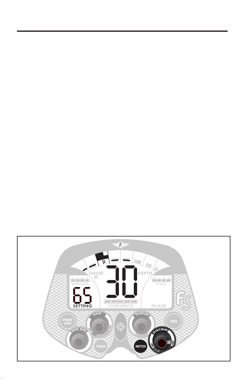
UUnnddeerrssttaannddiinngg tthhee DDiissppllaayy .. .. .. .. .. .. .. .. .. .. .. .. .. .. .. .. .. .. .. .. .. ..1199--2200
MMooddee IInnddiiccaattiioonn .. .. .. .. .. .. .. .. .. .. .. .. .. .. .. .. .. .. .. .. .. .. .. .. .. .. .. ..1199
TTaarrggeett CCaatteeggoorriieess .. .. .. .. .. .. .. .. .. .. .. .. .. .. .. .. .. .. .. .. .. .. .. .. .. .. ..1199
DDiissccrriimmiinnaattiioonn IInnddiiccaattoorrss .. .. .. .. .. .. .. .. .. .. .. .. .. .. .. .. .. .. .. .. .. ..1199
TTaarrggeett IIDD .. .. .. .. .. .. .. .. .. .. .. .. .. .. .. .. .. .. .. .. .. .. .. .. .. .. .. .. .. .. .. .. .. .. ..1199
DDeepptthh .. .. .. .. .. .. .. .. .. .. .. .. .. .. .. .. .. .. .. .. .. .. .. .. .. .. .. .. .. .. .. .. .. .. .. .. ..1199
CCoonnffiiddeennccee .. .. .. .. .. .. .. .. .. .. .. .. .. .. .. .. .. .. .. .. .. .. .. .. .. .. .. .. .. .. .. ..1199
BBaatttteerryy IInnddiiccaattoorr .. .. .. .. .. .. .. .. .. .. .. .. .. .. .. .. .. .. .. .. .. .. .. .. .. .. .. ..2200
%% FFee
33OO44
.. .. .. .. .. .. .. .. .. .. .. .. .. .. .. .. .. .. .. .. .. .. .. .. .. .. .. .. .. .. .. .. .. .. .. .. ..2200
PPhhaassee .. .. .. .. .. .. .. .. .. .. .. .. .. .. .. .. .. .. .. .. .. .. .. .. .. .. .. .. .. .. .. .. .. .. .. .. .. ..2200
SSeettttiinngg .. .. .. .. .. .. .. .. .. .. .. .. .. .. .. .. .. .. .. .. .. .. .. .. .. .. .. .. .. .. .. .. .. .. .. .. ..2200
SSeeaarrcchh TTeecchhnniiqquueess
. . . . . . . . . . . . . . . . . . . . . . . . . . . . . . .
2211
TTaarrggeett VVeerriiffiiccaattiioonn .. .. .. .. .. .. .. .. .. .. .. .. .. .. .. .. .. .. .. .. .. .. .. .. .. .. ..2211
PPiinnppooiinnttiinngg wwiitthh mmoottiioonn mmooddeess .. .. .. .. .. .. .. .. .. .. .. .. .. .. .. ..2211
TTaarrggeett PPiinnppooiinnttiinngg ((NNoo mmoottiioonn))
. . . . . . . . . . . . . . . . . . . . .
2222
UUnniitt SSppeecciiffiiccaattiioonnss
. . . . . . . . . . . . . . . . . . . . . . . . . . . . . . .
2233
Page 3
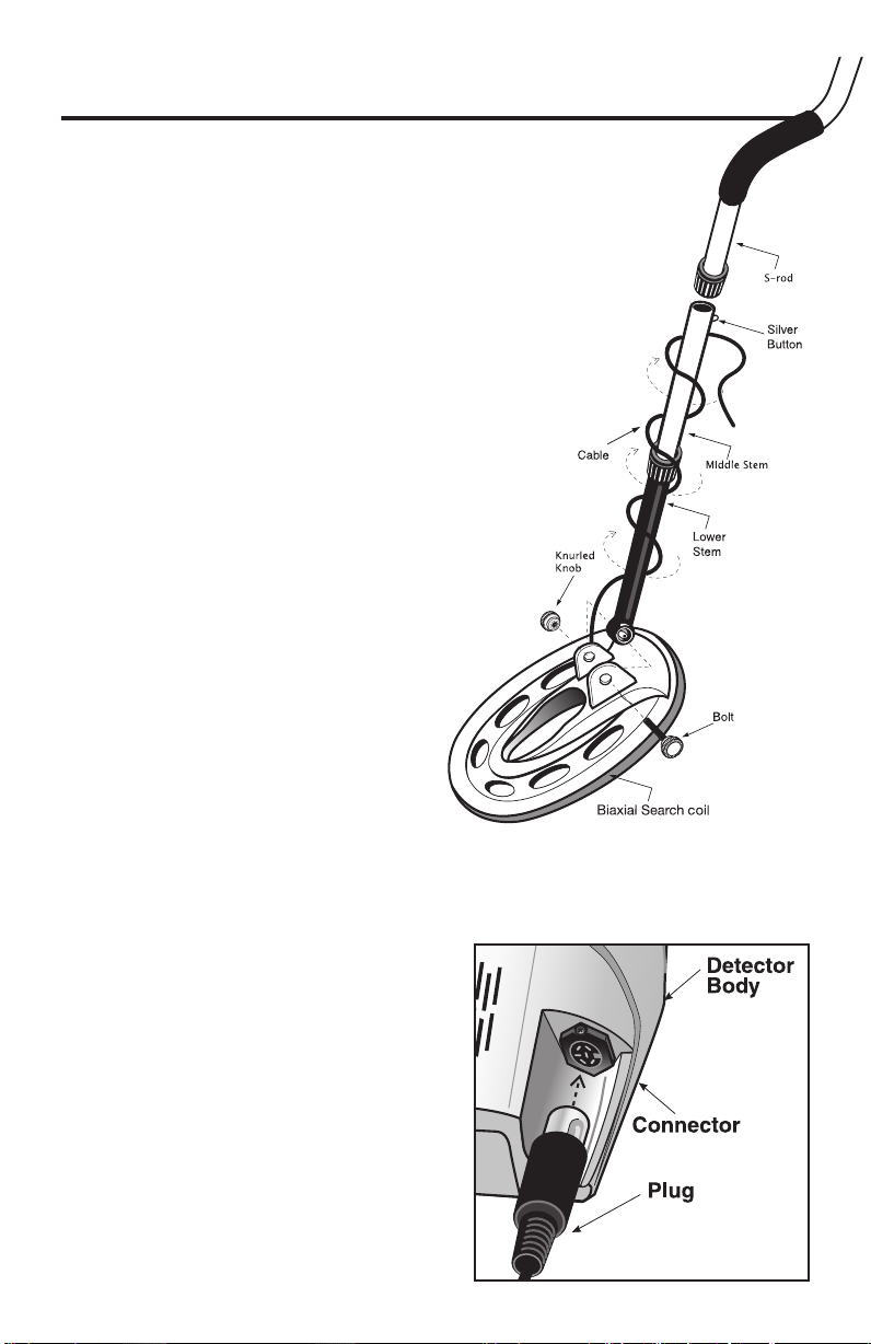
SETTING UP
No tools required.
11
Insert the lower stem (plastic tube) into the middle stem.
!
22
Position the stems with the silver buttons toward the
!
back.
Using the bolt and knob, attach the search coil to
the lower stem.
33
Press the button on the middle stem, and slide the
!
stem assembly into the s-rod.
Adjust the stem to a length that lets you
maintain a comfortable upright posture, with
your arm relaxed at your side, and the search
coil parallel to the ground in front of you.
44
Wind the cable securely around the stem.
!
55
Insert the plug into the matching
!
connector on the right underside of the
detector body. Be sure that the key-way
and pins line up correctly.
66
After the stem length is adjusted
!
to your height, tighten the two
locking collars to stabilize the
stems.
77
Secure the cable to the stem
!
with Velcro strips at the top and
bottom. Secure one at the bottom of the plastic tube, and one to the
aluminum tube, close to the detector housing. It is important to secure
the cable; a loose cable may result in erratic sounds.
Arm Rest Adjustment
If you wish to change the position of
the arm rest, remove the screw and
move the arm rest to one of the
alternate hole locations.
Caution: Do not force the plug in.
Excess force will cause
damage.
To disconnect the cable, pull
on the plug.
Do not pull on the cable.
33
Page 4
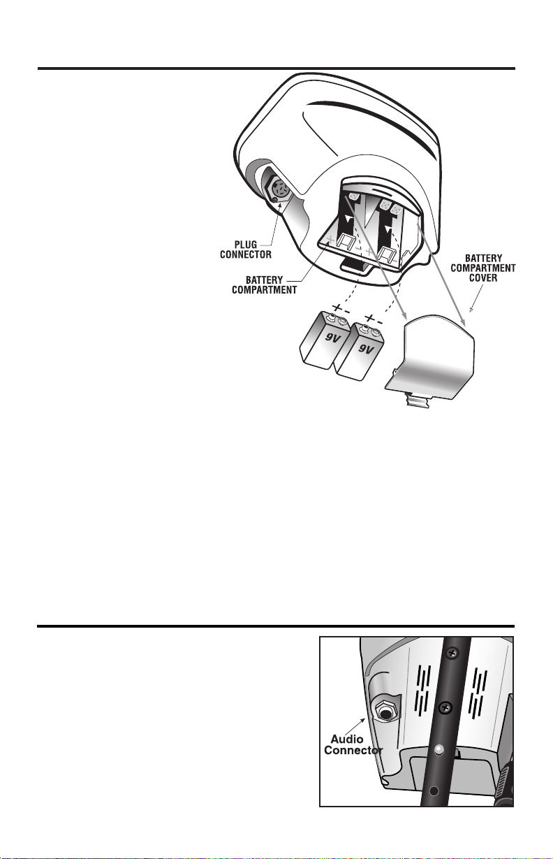
BATTERIES
TTwwoo 99--VVoolltt bbaatttteerriieess aarree
ssuupppplliieedd wwiitthh tthhee FF55..
The batteries have been
inserted backwards in the
compartment for storage
during transportation.
Please remove batteries,
turn them around, and install
correctly.
AALLKKAALLIINNEE
Use
only.
DDoo nnoott mmiixx oolldd aanndd nneeww
bbaatttteerriieess..
To install the batteries:
11
Remove the battery cover
by disengaging the clip at the
back.
DDoo nnoott hhiinnggee ddoooorr uuppwwaarrdd
straight back
22
Align the polarity of the batteries correctly, with the positive "+"
toward the coil plug connection, as indicated by the + indicator
on the housing.
33
Insert (2) 9-Volt
and press down on the back of the batteries to snap them into place.
Some brands of batteries will require moderate force to clear the
retaining tabs.
44
Replace the battery door.
Most metal detector problems are due to improperly installed
batteries, or the use of non-alkaline or discharged batteries.
ddeetteeccttoorr ddooeess nnoott ttuurrnn oonn,, pplleeaassee cchheecckk tthhee bbaatttteerriieess..
batteries
AALLKKAALLIINNEE
; pull
batteries, with the contacts pointed inward,
IIff tthhee
USING HEADPHONES
Using headphones (not supplied) improves
battery life, and prevents the sounds from
annoying bystanders.
It also allows you to hear subtle changes in the
sound more clearly, particularly if searching in a
noisy location. For safety reasons, do not use
headphones near traffic or where other
dangers are present. This device is to be used
with interconnecting cables/headphone
cables shorter than three meters.
44
Page 5
QUICK-START DEMONSTRATION
TARG ET
ID
D E P T H
11.. SSuupppplliieess NNeeeeddeedd
• A Nail • A Zinc Penny (dated after 1982)
• A Nickel • A Quarter
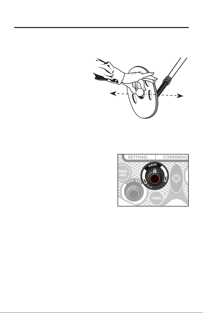
22.. PPoossiittiioonn tthhee DDeetteeccttoorr
a. Place the detector on a
table, with the search
coil hanging over the
edge. (or better, have a
friend hold the detector,
with the coil off the
ground).
b. Keep the search coil
away from walls, floors,
and metal objects.
c. Remove watches, rings
and other jewelry or metal objects from hands and wrists.
d. Turn off appliances or lights that cause electromagnetic
interference.
e. Pivot the search coil back toward the detector body.
33..PPoowweerr UUpp
a. Click on the On/Off/Gain knob
b. Set Gain Knob at the 12:00 position
c. Rotate threshold knob to setting= -3
44.. AAccttiivvee DDiissccrriimmiinnaattiioonn MMooddee
Click on “Discrim” knob and keep to
left, at lowest setting.
55.. WWaavvee eeaacchh oobbjjeecctt oovveerr tthhee sseeaarrcchh ccooiill
• Notice the low tone for the nail.
66.. WWaavvee aa ccooiinn cclloossee ttoo,, tthheenn ffaarrtthheerr aawwaayy,, ffrroomm tthhee sseeaarrcchh ccooiill
• Notice that pitch and volume increase as non-ferrous objects get
closer to the search coil.
77..PPrreessss tthhee TTOONNEESS ttoouucchhppaadd
Number of tones setting changes to d3.
88..WWaavvee eeaacchh oobbjjeecctt oovveerr tthhee sseeaarrcchh ccooiill
Notice the 3 different tones
• Low tone: nail
• Medium tone: nickel and zinc penny
• High tone: quarter
55
Page 6
QUICK-START DEMONSTRATION
TAR GE T
ID
D EP TH
(continued)
99.. RRoottaattee tthhee DDIISSCCRRIIMM kknnoobb uunnttiill 1155 aappppeeaarrss aatt tthhee lleefftt
ooff tthhee ddiissppllaayy
1100.. WWaavvee eeaacchh oobbjjeecctt oovveerr tthhee sseeaarrcchh ccooiill
Notice that the nail is not detected.
1111.. RRoottaattee tthhee DDIISSCCRRIIMM kknnoobb uunnttiill 6655 aappppeeaarrss aatt tthhee lleefftt ooff tthhee ddiissppllaayy
1122.. WWaavvee eeaacchh oobbjjeecctt oovveerr tthhee sseeaarrcchh ccooiill
— Notice that now only the quarter is detected.
— The other objects have been “discriminated out”
1133.. PPrreessss tthhee NNOOTTCCHH ttoouucchhppaadd 33 ttiimmeess uunnttiill tthhee ffllaasshhiinngg lliinnee
iiss oovveerr tthhee 55¢¢ iiccoonn
After a few seconds, the flashing stops
Notice that there is now no slash over the 5¢ icon
1144.. WWaavvee aallll oobbjjeeccttss oovveerr tthhee sseeaarrcchh ccooiill..
Notice that the nickel is now detected. You have “notched in”
the nickel.
In categories covered with a slash, objects will not be detected.
1155.. PPrreessss--aanndd--HHoolldd tthhee PPIINNPPOOIINNTT ttoouucchhppaadd
Hold an object over the search coil.
All metal objects are now detected.
The object’s DEPTH is displayed, in inches, in the center
of the display.
Pitch and volume increase as objects get closer to the coil.
55
65
7
5
85
9
9
GND DATA
STATUS
5
1
25
5
3
66
Page 7
CONTROL PANEL
TThhee TToouucchh PPaadd ccoonnttrroollss aarree aass ffoolllloowwss::
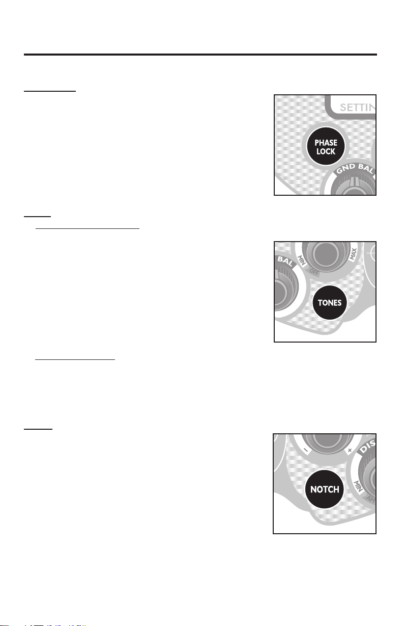
PHASE LOCK
Pressing “Phase Lock” will update the internal
ground balance setting.
We recommend pumping the coil, as described
in the GROUND BALANCING section of the
manual, when using this control. Be aware that
a momentary press of the PHASE LOCK button
will automatically transfer the currently
displayed PHASE value to the GROUND SETTING.
TONES
In Discrimination mode, the F5 indicates target type by audio tone.
The TONES button allows the user to select one
of four different ways to group target types by
tone.
Your selection depends on personal preference
and search objectives. For example, coin
shooters usually select d3 or d4. Relic hunters
might select d1 or d2, depending on search
area conditions.
In All-Metals mode
the base tone.
See page 16 for a detailed description of the tones provided for each
selection.
, the TONES button allows the user to vary the pitch of
NOTCH
The purpose of the NOTCH function is to
change the detection status of a target
category.
• If a category was not eliminated from
detection before being “notched,” then
notching the category will eliminate it from
detection.
• If a category was eliminated from detection
before being “notched,” (i.e. a “
covered the icon), then notching the category will return the
category to detection.
Touch Pad controls continued on next page
--
”
77
Page 8
CONTROL PANEL
TToouucchh PPaadd ccoonnttrroollss ccoonnttiinnuueedd
Upon the 1st press of NOTCH, a “--” will flash over the “Fe” symbol.
Each subsequent press will move the flashing “
The following target categories can be notched in or out:
Fe, Foil, 5¢, Tab, Zinc, 50+
After the 50+ category, pressing NOTCH will exit the NOTCH function.
To select a category for notching, press NOTCH until the flashing “
appears over that category’s icon. After a few seconds, the flashing “--”
will time out and the current target category will be notched.
Practice pressing NOTCH a few times and its function will become obvious.
The NOTCH feature is not available in Auto Tune Mode.
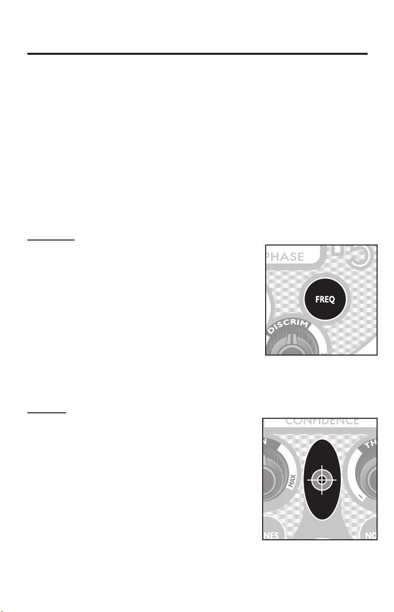
FREQUENCY
Use this control if detector behaves erratically
and you suspect electromagnetic
interference from some other electronic
device. The control will change the detector’s
operating frequency. Press until you find one
of the frequencies which minimizes the
interference.
Choices are:
1 – default frequency
2 – 1st alternate frequency
3 – 2nd alternate frequency
Changing frequency may require you to change the ground balance
setting. See section on ground balancing.
” to the right.
--
--
”
PINPOINT
This touchpad, in the middle of the panel,
activates the PINPOINT mode.
Press-and-Hold this touchpad for static
detection.
Volume and pitch increase with increase in
signal strength.
Target DEPTH, in inches, will be indicated in
the middle of the display.
The depth indicator is calibrated to coin-sized
objects. Objects other than coins will indicate
relative depth readings.
88
Page 9

CONTROL PANEL
TThhee CCoonnttrrooll KKnnoobb ffuunnccttiioonnss aarree aass ffoolllloowwss::
GND BAL
— Ground Balance
Control Knob
Rotate GND BAL to change
the detector’s internal Ground
Balance Setting.
By calibrating the detector to
the actual Ground Phase of
the soil you are searching, you
will cancel out signals from the
earth’s naturally occurring
minerals, thereby improving your ability to detect buried metal objects.
The default ground setting is 82.
The knob has no minimum or maximum set point; it rotates
continuously without a stop.
The faster you turn the knob, the more quickly the ground setting
changes. To make small changes to the ground setting, move the
knob slowly, one click at a time.
There are over 1,000 different ground balance settings, but only 100
different numbers are displayed on the screen, as 2-digit numbers
from 00 to 99. The displayed setting will change by one number for
roughly 10 clicks of the knob.
See section on Ground Balancing for a detailed description.
GAIN
The gain control increases, or multiplies, the signal from a buried metal
object.
Rotate the GAIN knob clockwise in order to increase the size of signals
generated. For maximum
detection of the smallest or
most deeply buried objects,
increase the gain. To minimize
the weakest signals, set the
gain at a low level.
There are 20 gain settings. 5 is
the lowest; 99 is the highest.
99
Page 10

CONTROL PANEL
CCoonnttrrooll kknnoobb ffuunnccttiioonnss ccoonnttiinnuueedd
THRESHOLD
The THRESHOLD control function
varies, depending on the mode
selected.
In DISCRIMINATION MODE,
nneeggaattiivvee
suppress sensitivity. The lower the
value, the greater the
suppression. This control can be
used to eliminate electrical interference or to eliminate response from
small trash objects.
threshold values
In discrimination mode,
ppoossiittiivvee
threshold values amplify the audio
response of weak target signals. Positive threshold selections make
weak targets easier to hear (if, for example detecting in a noisy
location). If it is necessary to reduce sensitivity, reduce GAIN while
maintaining positive threshold values.
In AUTOTUNE MODE, the threshold control can be used in two ways.
For searching at maximum sensitivity
, set threshold into the positive
region, with a comfortable background hum volume level. Then
reduce gain if necessary to reduce chatter.
For silence searching
, set threshold to a negative number, and also
reduce gain if necessary. Silent searching will result in the loss of
some sensitivity.
Threshold values range from -9 to 9. With the knob at the 12:00position, threshold will be between -1and -3.
DISCRIM (Mode Selection)
• Click into the far-left position,
and the detector enters ALL
METALS mode.
STATUS
25
5
1
55
6
5
3
5
7
5
8
5
GND DATA
• Click to the right, without
rotating, and the detector
enters DISCRIMINATION mode,
with multi-tone audio target
identification, and no metals
eliminated from detection.
• Rotate the knob to the right
to eliminate unwanted
metals from detection.
99
1100
Page 11

CONTROL PANEL
CCoonnttrrooll kknnoobb ffuunnccttiioonnss ccoonnttiinnuueedd
As you rotate the DISCRIM knob:
• The SETTING value will indicate the target-ID number to be
“discriminated out,” or eliminated from detection. All targets with
an ID less than or equal to the SETTING value will not be detected.
• A “
discriminated out.
” will appear over icons for those categories being
--
Note that the “
are discriminated out.
For example, if the DISCRIM knob is set at a SETTING of 55, a “
appear over “TAB.” Those objects in the tab category with values from
36 to 55 will not be detected. Objects with values of 56 and up will be
detected.
The audio and visual target discrimination systems are independent of
one another. In some situations, targets eliminated from visual
detection will still produce an audible response. Also, the audible
target identification may differ from the visual. The audio discrimiation
system provides more information about the target than the visual
system. Understanding the nuance of the detector’s audio feedback
requires some experience.
” will appear when all numbers within that category
--
--
STATUS
CCoonnttrrooll SSeettttiinnggss DDiissppllaayy
The setting for each control is displayed as a
2-digit number on the bottom left of the screen.
Each time you turn a control knob, or press FREQ
or TONES, the setting for that control is
immediately displayed above the word “SETTING.”
This 2-digit display value will revert back to the
Ground Balance setting after a control is not
adjusted for a few seconds.
When the SETTING value represents the Ground Balance setting,
“GND BAL” will be displayed next to the number.
” will
SSeettttiinngg MMeemmoorryy
The position of the GAIN, THRESHOLD, and DISCRIM control knobs always
indicates the setting of these controls.
The GND BAL setting, as well as the FREQ, TONES, and NOTCH values, are
not permanently saved to memory and will reset to default values when
the detector is powered off.
11111144
Page 12

GROUND BALANCING
What is Ground Balancing?
Why do I need to Ground Balance?
All soils contain minerals. Signals from ground minerals
are often tens or hundreds of times as strong as the
signal from a buried metal object. The magnetism of
iron minerals, found in nearly all soils, causes one
type of interfering signal. Dissolved mineral salts,
found in some soils, are electrically conductive,
causing another type of interfering signal.
Ground Balancing is the process by which the metal detector cancels
the unwanted signals coming from the ground minerals while still
detecting the signals from buried metal objects. This is accomplished
by matching the detector’s ground balance setting to the phase of
the ground signal.
When the detector is calibrated to the soil, the result will be deeper target
detection, quieter operation, and more accurate target identification.
HHooww ttoo GGrroouunndd BBaallaannccee yyoouurr ddeetteeccttoorr::
Ground Balancing procedure with the “Phase Lock” touchpad.
11..
Turn the F5 on and select AM (All-Metals) mode.
22..
Find a clear piece of ground with no metal
present, using All-Metals or Pinpoint mode.
(Note: Pinpoint preferred)
33..
Set the threshold to a slight background hum.
(Note: default setting of “0” is adequate)
44..
Press and hold the Phase Lock touch pad, and
pump coil over clean ground.
(Note: pump coil from 1” off ground to 6-8” off ground)
55..
When the phase value “settles down” to only one or two numbers
in variation, release the Phase Lock touch pad while still pumping
the coil. Note that the Audio Response to the ground changed
and “EVENED OUT” when you released the button. Also note that
the Gnd Bal setting changed to match the Phase Value, giving
you a visual AND audio Ground Balance confirmation. After
balancing, you can hunt in All-Metals... or return to Disc Mode.
To maintain the best ground balance setting for your detector, the GND
BAL setting on the left of the screen should always approximate the
PHASE value on the right of the screen.
The most accurate PHASE value is the value displayed when “pumping”
the coil over the ground in an area free of metal.
1122
Page 13

GROUND BALANCING – Technical Information
Understanding ground conditions assists the user in setting up the
machine, knowing when to readjust ground balance, and in
understanding the responses of the machine while searching. The
Fisher F5 provides two kinds of ground data:
mineralization (the greater the amount of mineralization, the greater the
loss of detection depth & ID accuracy; this loss is more pronounced in
Discrimination Mode)
where the ground balance should be set).
22..
the type of mineralization (which affects mostly
11..
the amount of
FFee33OO
The Fe3O44-segment bar graph indicates the amount of ground
mineralization, independent of type, expressed as an equivalent volume
concentration of magnetite (Fe3O4). It updates every second. It is
sensitive to motion and will give the most accurate readings if you
“pump” the search coil up and down several times over the ground. The
presence of metal or “hot rocks” will cause the readings to be inaccurate.
If you stop moving the search coil, the bar graph will go blank.
Magnetic susceptibility is expressed in micro-cgs units. In a salt water
environment in the absence of iron minerals, the bar graph indicates
relative electrical conductivity.
In soils with greater than 4,000 micro-cgs units magnetic susceptibility, the
signal from the soil may saturate (“overload”) the circuits. This will not harm
the detector but the machine will not be usable in that condition. The
solution is to hold the search coil several inches above the soil surface so
it isn’t “seeing as much dirt”. By listening and watching you will know how
high you need to hold the search coil in order to avoid overload.
BBAARR GGRRAAPPHH
44
IINNDDIICCAATTIIOONN %% FFee33OO
H — HIGH 0.4 - 1.6 1,000 - 4,000
M — MEDIUM 0.1 - 0.4 250 - 1,000
L — LOW 0.025 - 0.1 60 - 250
VL — VERY LOW 0.006 - .025 15 - 60
none - - less than .006 less than 15
44
SSUUSSCCEEPPTTIIBBIILLIITTYY
The highest magnetic susceptibilities are usually found in soils developed
over igneous rocks, in alluvial ‘black sand” streaks on beaches, and in
red clay soils of humid climates.
The lowest magnetic susceptibilities are usually found in white beach sands
of tropical and subtropical regions, and soils developed over limestone.
1133
Page 14

GROUND BALANCING
75
85
99
GND DATA
–
Technical Information
motion. The most repeatable measurements can be achieved by
“pumping” the search coil up and down over the soil surface. The
presence of metal or “hot rocks” will result in inaccurate readings. If
motion of the search coil stops, the phase readout will produce
meaningless readings.
(continued)
PPHHAASSEE
The phase readout at the bottom-
right of the screen provides a two-
digit 0 - 99 numeric indication of
the magnetic “loss angle” of the
soil minerals. The numerical
scale is the same one used for
ground balancing. When the
phase readout (verified by
pumping the coil over the
ground) is indicating numbers
which are consistently above
or below your present
ground balance setting
(indicated on the lower left
of the display), you will
probably want to readjust
your ground balance. This
is especially important if
you’re operating in All
Metals mode.
The Phase readout requires
that the search coil be in
The numeric scale does not indicate actual degrees, but rather the
scaling of the signals used to balance the ground signal. These signals
are scaled to give the greatest phase resolution in nonconductive soils
high in magnetite, where the greatest resolution is needed.
Page 15

GROUND BALANCING
–
Technical Information
(continued)
PPHHAASSEE
IINNDDIICCAATTIIOONN CCOOMMMMEENNTTSS
continued
99 loss angle of -1.5 degrees
upper limit of ferrite balance tolerance band
83 loss angle = 0 degrees; nominal ferrite balance
71 loss angle = 1.5 degrees
lower limit of ferrite balance tolerance band
60 loss angle = 3.6 degrees
50 loss angle = 6.0 degrees
40 loss angle = 9.6 degrees
30 loss angle = 15.3 degrees
20 loss angle = 25.8 degrees
10 loss angle = 47 degrees
0 loss angle = 90 degrees
Electrical ferrite and magnetite (a naturally occurring form of ferrite) will
usually read about 83. However, due to calibration drift due to time
and temperature change, or the use of different search coils, ferrite
may read anywhere within the total tolerance band of 71 to 99 without
significant impairment of operation. Freshly weathered rocky soils and
sands (other than white beach sand) will usually read higher than 65.
Silt and loam soils will usually read above 55. Red clay soils will usually
read above 45 but lower than 75. Soils reading between 10 and 45
are usually low in mineralization as indicated by the Fe
usually electrically conductive, and are often high in smectite clays.
Soils in the range of 0 to 10 are rarely encountered other than in a moist
saline or alkali environment with little or no iron mineralization. White
sands will usually give no reading.
O4bargraph, are
3
1155
Page 16

AUDIO TARGET IDENTIFICATION SYSTEM
Different types of metals will induce different types of sounds,
depending on your TONES setting.
There are 4 choices in DISCRIMINATION MODE
dd11..
Medium-to-high pitch tone, varying in proportion to
target signal strength. Large shallow objects will
produce a squeal. The variable audio pitch provides
you more information about the detected object.
Volume and Pitch increase with increase in signal
strength.
dd22..
Iron produces a low-pitch tone regardless signal
strength. Volume varies in proportion to signal
strength. Non-ferrous targets respond as in d1.
dd33..
Three different audio tones.
Low Tone: Iron
High Tone: Foil, 5¢, Tab and Zinc
Very High Tone: Dime, 25¢, and 50+
dd44..
Four Different audio tones
Low Tone: Iron
Medium Tone: Foil, Tab, and Zinc
High Tone: 5¢
Very High Tone: Dime, 25¢ and 50+
The default setting is d2.
To choose from the above selections, press the TONES touch pad.
Each press of the TONES touch pad cycles to the next selection.
:
There are 4 choices in ALL-METALS MODE
A1, A2, A3, A4 - pitch varies with each setting.
1166
Page 17

DEPTH AND TARGET DISPLAY
READING THE DISPLAY
The Liquid Crystal Display (LCD) shows
the PROBABLE identification of the
targeted metal, as well as the
PROBABLE depth of the target, in
inches.
The detector will normally register a
repeating, unchanging target
identification when a buried target
has been located and identified. If,
upon repeated passes over the same
spot, the target identification reads
inconsistently, the target is probably a
trash item, oxidized metal, or too
deep to be classified accurately. With
practice, you will learn to unearth
only the more repeatable signals.
The segment identifications are highly
accurate when detecting the objects
described on the screen. However, if
you register in a given category for an
unknown buried object, you could be
detecting a metallic object other
than the object described on the
screen, but with the same metallic
signature. Also, the greater the
distance between the target and the
coil, the less accurate the target
identification.
GGOOLLDD TTAARRGGEETTSS
register on the left side of the LCD
scale. Gold is categorized depending
on its size. The smaller the gold object,
the further to the left it will register.
SSmmaallll ggoolldd iitteemmss
Fe or Foil.
MMeeddiiuumm--ssiizzeedd ggoolldd iitteemmss
register under 5¢ or Tab.
LLaarrggee ggoolldd iitteemmss
Gold objects will
will register under
will usually
will usually
register under Tab or Zinc.
SSIILLVVEERR TTAARRGGEETTSS::
normally register to the right of the
scale, under Dime, Quarter, or 50+,
depending on the size of the object.
The larger the object, the farther to
the right it will register.
IIRROONN::
Fe is the scientific designation
for Iron. Most iron objects will fall into
the Fe category. Very large iron
objects like a manhole cover will
usually fall into the 50+ category.
55¢¢::
Nickels and most newer pull-tabs
will register here.
TTAABB::
Older pull-tabs and ring-pulls
from beverage cans usually will
register here. Many gold rings will also
register here.
ZZIINNCC//11¢¢::
will register here. Many non-U.S. coins
will also register here.
Screw caps from glass bottles will
register here. Large gold rings, like a
class ring, could also register here.
DDIIMMEE::
pennies will register here.
CCaauuttiioonn::
visual references. Many other types of
metal can fall under any one of these
categories. While the F5 will eliminate
or indicate the presence of most
common trash items, it is impossible to
accurately classify ALL buried objects.
Newer pennies (post-1982)
Dimes and pre-1982 copper
The target indications are
Silver objects will
1177
Page 18

DEPTH AND TARGET DISPLAY
RReeaaddiinngg tthhee ddiissppllaayy ccoonnttiinnuueedd
DEPTH INDICATOR:
The Depth Indicator is calibrated for
coin-sized objects. It indicates the
probable depth of the target, in
inches.
middle of the LCD display, provides a
specific target value to help identify
buried targets more accurately. With
practice in the field, you will learn to
associate target values with the
probable identification of buried objects.
While holding the PinPoint touch pad,
and passing over a metal object
“depth” will appear next to the two-digit
number in the middle of the screen.
The target value can vary each time the
coil passes over the target, depending
upon the angle of the object and the
distance from the coil.
AAss aa ssttaarrttiinngg ppooiinntt,, rreeffeerr ttoo tthhee
TWO DIGIT TARGET INDICATOR
ttaabbllee bbeellooww..
The Two-digit target indicator, in the
TTAARRGGEETT RReeaaddoouutt
The table below lists some common approximate target value equivalents.
With experience in the field, you will recognize many types of metal objects
by their numeric value.
TTYYPPIICCAALL VVAALLUUEE
0-15 Iron
20-24 Pull-Tab Tail
30-32 Nickel, Old style pull tab
36-42 Pull-Tab (new style), Ring Pull
58-60 Zinc Penny
70 Dime & Copper Cent
80 Quarter
88 Half Dollar
92 Silver Dollar
PPOOSSSSIIBBLLEE OOBBJJEECCTTSS
(broken off),
Aluminum Foil
1188
Page 19

UNDERSTANDING THE DISPLAY
TAR GE T
ID
D EP TH
MMooddee IInnddiiccaattiioonn
The search mode is
briefly displayed in the
center of the screen
each time you
change modes, as
follows:
5
1
STATUS
6 7 8 9
BATTERY VOLTS
SETTING
25
TAR GE T
ID
GND
BAL
55
5
3
CONFIDENCE
65
7
5
8
5
99
GND DATA
D EP TH
VL L M H
% Fe3O
4
PHASE
All Metals
Discrimination
Pinpoint
TTaarrggeett CCaatteeggoorriieess
There are 8 categories, indicated at the top of the display.
When the search coil passes over a metal object in DISCRIMINATION
or ALL METALS mode, a rectangular-shaped icon will light up over the
category which describes the metal object.
DDiissccrriimmiinnaattiioonn IInnddiiccaattoorrss
When a “—” appears over the target category descriptions, all of the
targets in that category have been eliminated from detection.
Rotate the DISCRIM knob to choose the discrimination setting.
TTaarrggeett IIDD
A 2-digit number will appear when passing over a metal object in
DISCRIMINATION or ALL METALS mode. This 2-digit number
corresponds to the target categories at the top of the display.
DDeepptthh
When holding the PINPOINT touch pad, the 2-digit number in the center
of the display shows the distance to the object, in inches. This depth
indicator is calibrated to coin-sized objects. If the buried object is other
than a coin, the depth indicator provides a relative depth indication.
CCoonnffiiddeennccee
While the Target ID provides a target identification, it is not possible to
always be 100% accurate of the buried object’s classification due to
the large variety of buried metal objects. To assist with target
identification refer to this confidence meter.
If the detector is highly confident an object’s classification, all 5 bars
will illuminate.
One bar illuminated indicates a very low level of confidence in the
target identification.
1199
Page 20

TARG ET
ID
D E P T H
UNDERSTANDING THE DISPLAY
(continued)
BBaatttteerryy IInnddiiccaattoorr
Segments indicate the battery voltage, as printed on the display.
OO
%% FFee
33
44
This bar graph displays the magnetic mineralization factor, or magnetic
susceptibility, of the soil. The depth to which objects can be accurately
identified is strongly influenced by the magnetic susceptibility of the soil. High
Fe3O4values have a greater effect on detection depth in the Discrimination
mode than in the All Metal mode. For the most accurate Fe
3O4
reading,
pump the search coil as though you were ground canceling.
The % of Fe3O4ground minerals are displayed as follows:
H – high
M – medium
L – low
VL – very low
PPhhaassee
The two-digit PHASE number displayed on the screen indicates the type of
ground mineralization. The number is continuously displayed in all
detection modes except Pinpoint, and is continually updated. Ground
conditions can change within a given search area, sometimes slowly, and
sometimes quite abruptly. This number cannot be adjusted by the user.
Some typical ground mineralization types are:
0 – 10 Wet salt and alkali
5 – 25 Metallic iron
26 – 39 Very few soils in this range -- occasionally
some saltwater beaches
40 – 75 Red, yellow, and brown iron-bearing clay minerals
75 – 95 Magnetite and other black iron minerals
SSeettttiinngg
This 2-digit number on the bottom-left of the display can represent any
of the following:
• Internal Ground Balance setting (GND BAL): from 00 to 99
• Gain: 20 values from 5 to 99 in steps of 5
• Threshold: 19 values from -9 to 9
• Discrimination Setting: from 0 to 65
• Frequency: 1, 2, or 3
• Audio Tones Selection: d1, d2, d3, d4 or A1, A2, A3, A4
If the user is not moving any knobs or pressing any touchpads, then the
number represents the internal ground balance setting, and “GND
BAL” is illuminated.
“GND BAL” disappears when the user selects a control, and the
SETTING then represents the current value for the activated knob or
touch pad.
2200
Page 21

Page 22

TARGET PINPOINTING
After you have identified a target using a motion mode of detection,
press-and-hold the PINPOINT pad to identify the target’s exact
location. This technique can yield more information about the target’s
shape and size and also find its exact location to facilitate extraction.
PPiinnppooiinntt aass ffoolllloowwss::
11..
Position the search coil just barely off the ground, and to the side of
the target.
22..
Now move the search coil slowly across the target, and you can
locate it by the sound. The target is located directly under where
the sound is loudest.
NNaarrrrooww IItt DDoowwnn::
11..
To narrow the response further, position the center of the search coil
near the center of the response pattern, but not
directly over the center.
22..
Release the PINPOINT touch pad.
33..
44..
Repeat this narrowing procedure to narrow
the field of detection further.
NNoottee::
Depth indication is less accurate after
narrowing.
(in PINPOINT mode)
Press-and-hold PINPOINT pad again.
COIL DRIFT
If you plan to use the PINPOINT mode for continuous
searching, realize that drift will occur over time,
causing the detector to gain or lose sensitivity.
Periodic retuning of the detector is required to
minimize drift; release and press PINPOINT again
to retune.
2222
Page 23

UNIT SPECIFICATIONS:
MMeecchhaanniiccaall::
breakdown construction, nonmetallic telescoping lower rod,
adjustable position arm rest
WWeeiigghhtt::
SSttaannddaarrdd sseeaarrcchh ccooiill::
concentric, waterproof
BBaatttteerriieess::
OOppeerraattiinngg pprriinncciippllee::
OOppeerraattiinngg ffrreeqquueennccyy::
BBaassiicc sseennssiittiivviittyy::
LLaagg ccooeeffffiicciieenntt::
RReeaaccttiivvee oovveerrllooaadd::
RReessiissttiivvee oovveerrllooaadd::
GGrroouunndd bbaallaannccee rraannggee::
DDiissccrriimmiinnaattiioonn ggrroouunndd ssuupppprreessssiioonn::
methods
TTaarrggeett IIDD ggrroouunndd ssuupppprreessssiioonn::
BBaatttteerryy lliiffee::
OOppeerraattiinngg tteemmpp rraannggee::
OOppeerraattiinngg hhuummiiddiittyy rraannggee::
S-rod with electronics housing on rod, 3-piece
3.0 lbs (1.38 kg) with batteries installed
10 inch (25 cm) open-frame elliptical
two 9 volt rectangular alkaline (will run on one)
VLF induction balance
nominal 7.8 kHz, microprocessor controlled
9
2.5 x 10
92 milliseconds
40+ hours on good quality alkalines
root Hertz (detectivity)
5,000 micro-cgs (with standard search coil)
600 micro-cgs (with standard search coil)
from ferrite to salt water inclusive
combination of 2
rd
3
order
14 to 122 degrees F (-10 to +50 C)
0 - 90% noncondensing
nd
and 3rdorder
TREASURE HUNTER’S CODE OF ETHICS:
• Always check Federal, State, County and local laws before searching.
• Respect private property and do not enter private property without
the owner’s permission.
• Take care to refill all holes and try not to leave any damage.
• Remove and dispose of any and all trash and litter found.
• Appreciate and protect our inheritance of natural resources, wildlife
and private property.
• Act as an ambassador for the hobby, use thoughtfulness,
consideration and courtesy at all times.
• Never destroy historical or archaeological treasures.
• All treasure hunters may be judged by the example you set; always
conduct yourself with courtesy and consideration of others
2233
Page 24

55--YYEEAARR LLIIMMIITTEEDD WWAARRRRAANNTTYY
The F5 metal detector is warranted against defects in materials and
workmanship under normal use for five years from the date of purchase
to the original owner.
Damage due to neglect, accidental damage or misuse of this product is
not covered under this warranty. Decisions regarding abuse or misuse of
the detector are made solely at the discretion of the manufacturer.
PPrrooooff ooff PPuurrcchhaassee iiss rreeqquuiirreedd ttoo mmaakkee aa ccllaaiimm uunnddeerr tthhiiss wwaarrrraannttyy..
Liability under this Warranty is limited to replacing or repairing, at our
option, the metal detector returned, shipping cost prepaid to Fisher Labs.
Shipping cost to Fisher Labs is the responsibility of the consumer.
To return your detector for service, please first contact Fisher Labs for a
Return Authorization (RA) Number. Reference the RA number on your
package and return the detector within 15 days of calling to:
Fisher Labs
1465-H Henry Brennan Dr.
El Paso, TX 79936
Phone: 915-225-0333 ext.118
Warranty coverage does not include the cost of transporting the
detector back to an owner who is located outside of the United States of
America.
NOTE TO FOREIGN COUNTRY CUSTOMERS
This warranty may vary in other countries, check with your distributor for details.
Factory warranty follows the channel of distribution.
Warranty does not cover shipping costs.
All rights reserved, including the right to reproduce this book, or parts thereof, in any form.
Fisher®is a registered trademark of Fisher Research Labs
Copyright© 2009
www.fisherlab.com
MF5 B 1465-H Henry Brennan, El Paso, TX 79936 • (915) 225-0333 092209
 Loading...