

Fisher F19 Owner's Manual

OWNER’S MANUAL
TM
Use 9-volt
ALKALINE batteries.
Do not use
“Heavy Duty” batteries.
Do not use
ordinary “Zinc Carbon” batteries.

2
TABLE OF CONTENTS
Introduction . . . . . . . . . . . . . . . . . . . . . . . . . . . . . . . . . . . . . . . . . . . . . . . . . .3
Terminology . . . . . . . . . . . . . . . . . . . . . . . . . . . . . . . . . . . . . . . . . . . . . . . . . .4
Assembly . . . . . . . . . . . . . . . . . . . . . . . . . . . . . . . . . . . . . . . . . . . . . . . . . .5-6
Batteries . . . . . . . . . . . . . . . . . . . . . . . . . . . . . . . . . . . . . . . . . . . . . . . . . . . .7
Quick-Start Demo . . . . . . . . . . . . . . . . . . . . . . . . . . . . . . . . . . . . . . . . . . .8-9
Headphones . . . . . . . . . . . . . . . . . . . . . . . . . . . . . . . . . . . . . . . . . . .9
Basics Of Metal Detecting . . . . . . . . . . . . . . . . . . . . . . . . . . . . .10-11
Ground Minerals . . . . . . . . . . . . . . . . . . . . . . . . . . . . . . . . . . . . . . . .10
Trash . . . . . . . . . . . . . . . . . . . . . . . . . . . . . . . . . . . . . . . . . . . . . . . . .11
Identifying Buried Objects . . . . . . . . . . . . . . . . . . . . . . . . . . .11
Size and Depth of Buried Objects . . . . . . . . . . . . . . . . . . . . .11
electromagnetic Interference (e MI)
. . . . . . . . . . . . . . . . . . . .11
Operation and Controls . . . . . . . . . . . . . . . . . . . . . . . . . . . . . . . . . . . . . . . .12
Control Panel . . . . . . . . . . . . . . . . . . . . . . . . . . . . . . . . . . . . . . . . . . . . . . .13
Control Knobs
Off / On / Gain . . . . . . . . . . . . . . . . . . . . . . . . . . . . . . . . .13
Disc / All Metal / Threshold . . . . . . . . . . . . . . . . . . . . . . . .13
Touchpad Controls
Menu/
Ground Grab®(Computerized Ground Balancing)
. . . .14
+
and - . . . . . . . . . . . . . . . . . . . . . . . . . . . . . . . . . . . . . . .14
Pinpoint
. . . . . . . . . . . . . . . . . . . . . . . . . . . . . . . . . . . . . . .14
Operating in All Metal Mode
Ground Grab
®
(Computerized Ground Balancing) . . . . . . . .15
Setting the Controls . . . . . . . . . . . . . . . . . . . . . . . . . . . . . . . .15
Unwanted Noise . . . . . . . . . . . . . . . . . . . . . . . . . . . . . . . . . .15
Sweeping the Searchcoil . . . . . . . . . . . . . . . . . . . . . . . . . . . .15
r eading the Display . . . . . . . . . . . . . . . . . . . . . . . . . . . . . . .16
Target Scale . . . . . . . . . . . . . . . . . . . . . . . . . . . . . . . . . . . . .16
Operating in Discrimination Mode
Ground Grab
®
(Computerized Ground Balancing) . . . . . . . .17
Setting the Controls . . . . . . . . . . . . . . . . . . . . . . . . . . . . . . . .17
Gain . . . . . . . . . . . . . . . . . . . . . . . . . . . . . . . . . . . . . . . . . . . .17
Mode . . . . . . . . . . . . . . . . . . . . . . . . . . . . . . . . . . . . . . . . . . .17
MeNU . . . . . . . . . . . . . . . . . . . . . . . . . . . . . . . . . . . . . . . .17-19
Unwanted Noise . . . . . . . . . . . . . . . . . . . . . . . . . . . . . . . . . .20
Sweeping the Searchcoil . . . . . . . . . . . . . . . . . . . . . . . . . . . .20
Using Pinpoint . . . . . . . . . . . . . . . . . . . . . . . . . . . . . . . . . . . .20
r eading the Display . . . . . . . . . . . . . . . . . . . . . . . . . . . . .20-22
Ground Balancing . . . . . . . . . . . . . . . . . . . . . . . . . . . . . . . . . . .23-25
Ground Balancing Technical Info . . . . . . . . . . . . . . . . . . . . . . . . . .26
Target Display & Audio . . . . . . . . . . . . . . . . . . . . . . . . . . . . . . . . . .27
Gold Prospecting . . . . . . . . . . . . . . . . . . . . . . . . . . . . . . . . . . . . . .28
r elic Hunting . . . . . . . . . . . . . . . . . . . . . . . . . . . . . . . . . . . . . . . . .29
Hot r ocks . . . . . . . . . . . . . . . . . . . . . . . . . . . . . . . . . . . . . . . . . . . .30
electromagnetic Interference (e MI) . . . . . . . . . . . . . . . . . . . . . .31-32
Search Techniques . . . . . . . . . . . . . . . . . . . . . . . . . . . . . . . . . . . . .33
Target Pinpointing . . . . . . . . . . . . . . . . . . . . . . . . . . . . . . . . . . . . . .34
Optional 5”DD Searchcoil . . . . . . . . . . . . . . . . . . . . . . . . . . . . . . . . . . . . . .35
Device Specifications . . . . . . . . . . . . . . . . . . . . . . . . . . . . . . . . . . . . . . . . .36
Treasure Hunter’s Code of e thics . . . . . . . . . . . . . . . . . . . . . . . . . . . . . . . .36
Warranty . . . . . . . . . . . . . . . . . . . . . . . . . . . . . . . . . . . . . . . . . . . . . . . . . . .38
Accessories . . . . . . . . . . . . . . . . . . . . . . . . . . . . . . . . . . . . . . . . .Back Cover

3
Introduction to the F19
TM
The new F19™ is unique among relic hunting detectors for its versatile
function as an all-purpose treasure detector and also its high sensitivity to
small gold nuggets.
The controls, menu options and features are tailored to relic-hunting, including
a sophisticated ground balancing system, separate control over
signal gain and threshold and a unique discrimination control
system. These features also make for a great gold prospecting detector,
especially when the F19 is outfitted with the optional 5” DD
searchcoil. While the F19 makes for a highly competent coinshooting
detector, its user interface and features are not specifically
designed for this purpose. As a coin-shooter, you will notice that the
F19 exhibits slightly lower sensitivity to high-conductivity coins,
like a U.S. quarter; this is a result of its specialized design to
emphasize sensitivity to smaller, lower conductivity metals like relics and
gold nuggets.
The F19 is outfitted with a 10”DD closed elliptical searchcoil as standard
equipment since this searchcoil construction is best-suited to relic-hunting.
At the trashiest sites, you may find the smaller optional 5”DD searchcoil makes
pinpointing easier, is better suited to penetrate highly mineralized soils and
improves target separation.
Congratulations!
Congratulations on your purchase of the new F19™ metal detector. The F19™
has been custom designed to find the smallest targets, provide superior target
separation and features advanced discrimination control.
Whether you use your Detector in the backyard, at the shoreline, in the
mountains or fields afar, your investment will let you experience the excitement
of searching for yet to be discovered treasures and give you years of outdoor
enjoyment. Buried treasure can be as near as your own door step and stretch
from horizon to horizon. On your own or with friends, you’ll never run out of
places to use your F19.
This manual has been written to help you get optimal use of your detector, so we
hope you will read it thoroughly before your first outing and will also refer back to
this manual from time to time to reinforce features and methods as you become
more proficient in the field.
Happy Hunting from Fisher Research Labs!

4
TERMINOLOGY
The following terms are used throughout the manual, and are standard
terminology among detectorists.
RELIC
A relic is an object of interest by reason of its age or its association with
the past. Many relics are made of iron, but can also be made of bronze
or precious metals.
IRON
Iron is a common, low-grade metal that is an undesirable target in certain
metal detecting applications. examples of undesirable iron objects are old
cans, pipes, bolts and nails.
Sometimes, the desired target is made of iron. Property markers, for
instance, contain iron. valuable relics can also be composed of iron;
cannon balls, old armaments and parts of old structures and vehicles can
also be composed of iron.
FERROUS
Metals which are made of, or contain, iron.
ELIMINATION
r eference to a metal being "eliminated" means that the detector will not
emit a tone, nor display a Target-ID, when a metal object passes through
the searchcoil's detection field.
DISCRIMINATION
When the detector emits different tones for different types of metals, and
when the detector "eliminates" certain metals, we refer to this as the
detector "discriminating" among different types of metals.
Discrimination is an important feature of professional metal detectors.
Discrimination allows the user to ignore trash and otherwise undesirable
objects.
PINPOINTING
Pinpointing is the process of finding the exact location of a buried object.
Long-buried metals can appear exactly like the surrounding soil, and can
therefore be very hard to isolate from the soil.
V.C.O.
Meaning “voltage controlled oscillator,” the v.C.O. audio method causes
both the audio pitch and the volume to rise as signal strength increases.
v.C.O. improves the user's ability to interpret a target's size and depth.
very weak signals (for small or very deeply buried objects) have the
faintest volume and the lowest pitch. Larger objects, and those closer to
the searchcoil, will induce a higher volume and higher pitch sound.
GROUND BALANCING
Ground Balancing is the ability of the detector to ignore, or "see through,"
the earth's naturally occurring minerals, and only sound a tone when a
metal object is detected. This detector incorporates proprietary circuitry to
eliminate false signals from many mineralized soils.
According to FCC part 15.21 Changes or Modifications made to this device not expressly approved by
the party responsible for compliance could void the users authority to operate this equipment.
This equipment has been tested and found to comply with the limits for a Class B digital device,
pursuant to Part 15 of the FCC r ules. These limits are designed to provide reasonable protection
against harmful interference in a residential installation. This equipment generates, uses and can
radiate radio frequency energy and, if not installed and used in accordance with the instructions,
may cause harmful interference to radio communications. However, there is no guarantee that
interference will not occur in a particular installation. If this equipment does cause harmful
interference to radio or television reception, which can be determined by turning the equipment off
and on, the user is encouraged to try to correct the interference by one or more of the following
measures:
-- r eorient or relocate the receiving antenna.
-- Increase the separation between the equipment and receiver.
-- Connect the equipment into an outlet on a circuit different from that to which the receiver is
connected.
-- Consult the dealer or an experienced radio/Tv technician for help
This device complies with Industry Canada license-exempt r SS standard(s). Operation is subject
to the following two conditions: (1) this device may not cause interference, and (2) this device must
accept any interference, including interference that may cause undesired operation of the device.
This radio transmitter 8188A-F19MD has been approved by Industry Canada to operate with the
antenna types listed below with the maximum permissible gain and required antenna impedance
for each antenna type indicated. Antenna types not included in this list, having a gain greater than
the maximum gain indicated for that type, are strictly prohibited for use with this device.
Antennas:
1. 5” DD Coil, Part Number 5COIL-GBUG
2. 10” DD Coil,Part Number 10COILDD-Fr L
3. 11” DD Coil, Part Number 11COIL-GBUG
Under Industry Canada regulations, this radio transmitter may only operate using an antenna of a
type and maximum (or lesser) gain approved for the transmitter by Industry Canada. To reduce
potential radio interference to other users, the antenna type and its gain should be so chosen that
the equivalent isotropically radiated power (e.i.r.p.) is not more than that necessary for successful
communication.
Le présent appareil est conforme aux CNr d’Industrie Canada applicables aux appareils radio
exempts de licence. L’exploitation est autorisée aux deux conditions suivantes : (1) l’appareil ne
doit pas produire de brouillage, et (2) l’utilisateur de l’appareil doit accepter tout brouillage
radioélectrique subi, même si le brouillage est susceptible d’en compromettre le fonctionnement.
Le présent émetteur radio 8188A-F19MD a été approuvé par Industrie Canada pour fonctionner
avec les types d’antenne énumérés ci-dessous et ayant un gain admissible maximal et l’impédance
requise pour chaque type d’antenne. Les types d’antenne non inclus dans cette liste, ou dont le
gain est supérieur au gain maximal indiqué, sont strictement interdits pour l’exploitation de
l’émetteur.
Conformément à la réglementation d’Industrie Canada, le présent émetteur radio peut fonctionner
avec une antenne d’un type et d’un gain maximal (ou inférieur) approuvé pour l’émetteur par
Industrie Canada. Dans le but de réduire les risques de brouillage radioélectrique à l’intention des
autres utilisateurs, il faut choisir le type d’antenne et son gain de sorte que la puissance isotrope
rayonnée équivalente (p.i.r.e.) ne dépasse pas l’intensité nécessaire à l’établissement d’une
communication satisfaisante.
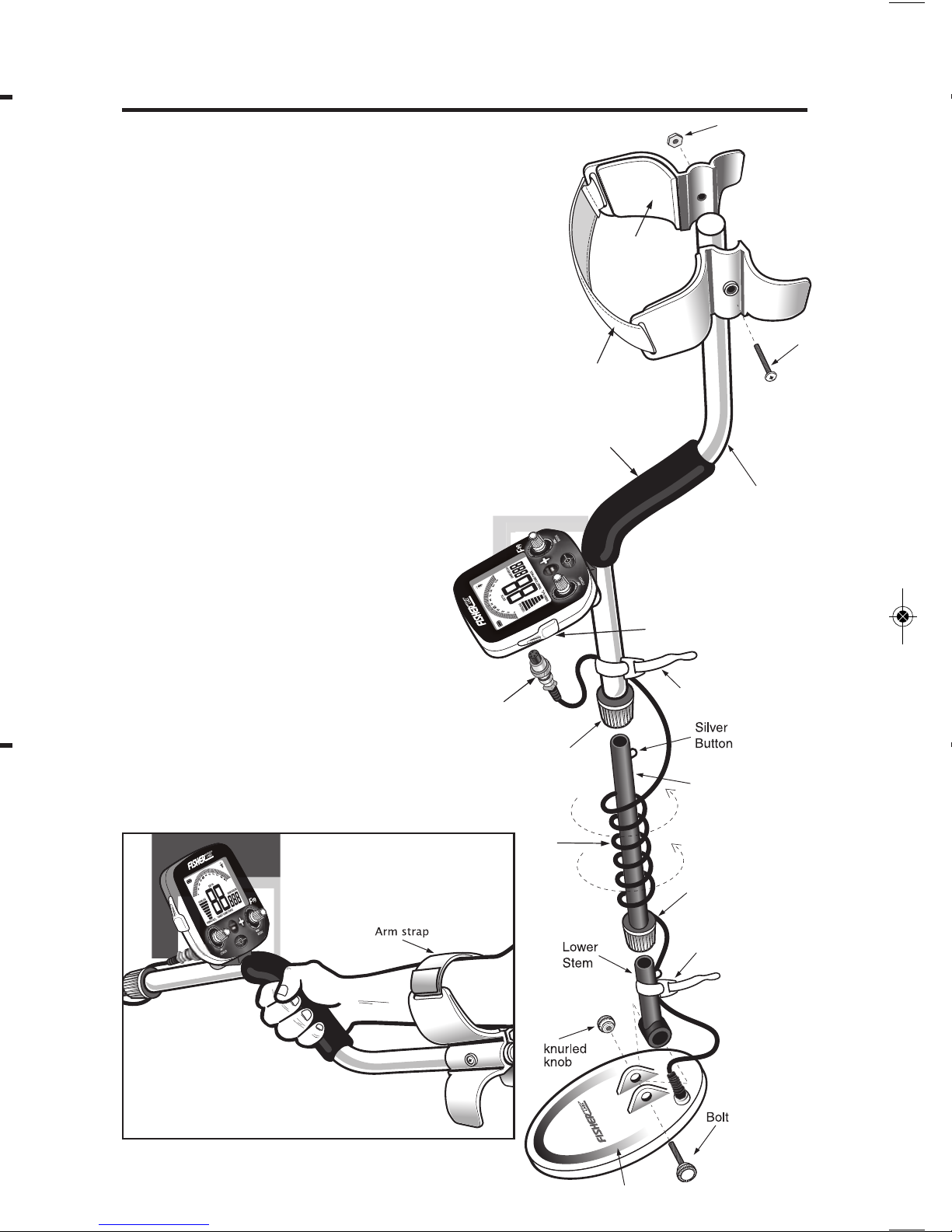
ASSEMBLY
Adjusting the Armrest
The armrest may be moved
forward or backward by removing
the single screw and nut, and then
repositioning the 2-piece armrest.
Users with shorter arms may find
the armrest more comfortable in
the forward position. In order to
move the armrest backward, the
plastic plug must be removed from
the aluminum tube.
Armrest Strap
Some users prefer to use the strap
when swinging the detector
vigorously, in order to hold the
detector securely against the arm.
The detector can always be used
without the strap, with no
compromise to detector balance
and stability under most conditions.
Hand-grip
Nut
Screw
Searchcoil
Cable
Cable
Plug
Searchcoil
S-Rod
Armrest
Arm Strap
Velcro
Strap
Middle
Stem
Velcro
Strap
Locking
Collar
Locking
Collar
1/4” Headphone Jack
VOLUME
V-BREAK
NOTCH WIDTH
DISCGND BAL
VOLUME
V-BREAK
NOTCH WIDTH
DISCGND BAL
5
6
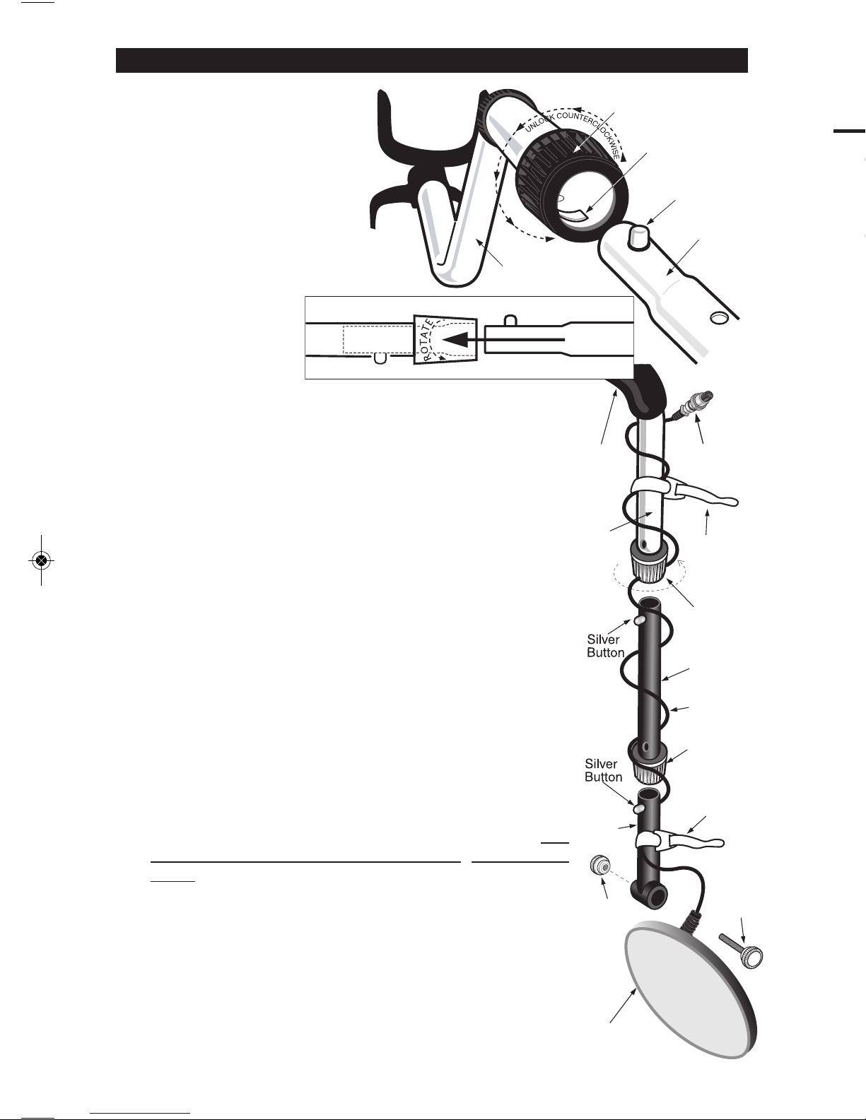
ASSEMBLY
Assembly is easy and
requires no tools.
●
1 Position S-rod upright.
●
2 rotate the
LOCKING COLLAr
fully in the
counterclockwise
direction.
●
3 Insert your finger
inside the tube and
make sure the INTer NAL CAM LOCK is flush with the
inside of the tube.
●
4
Insert the MIDDLe STeM into the S-r OD,
with the SILv e r BUTTON pointed upward
●
5 r otate the MIDDLe STeM until the SILv er BUTTON
snaps into the hole.
●
6 Twist the LOCKING COLLAr fully in the clockwise direction
until it locks.
●
7 r epeat this process on the LOWer STeM.
●
8 Using the BOLT and KNUr Le D KNOB, attach the
SeAr CHCOIL to the LOWer STeM.
●
9
Adjust the LOWer STeM to a length that lets you maintain a
comfortable upright posture, with your arm relaxed at your side,
and the SeAr CHCOIL parallel to the ground in front of you.
●
10
Wind the CABLe securely around the STeMS, leaving slack
at the bottom.
●
11
Connect CABLe PLUG to housing.
Do not twist the Cable or Plug. Turn Locking r ing only. Use
minimal finger pressure to start the threads. Do not crossthread. When the Locking r ing is fully engaged over the
threaded connector, give it a firm turn to make sure it is very
tight. When the Locking r ing is fully engaged over the
threaded connector, it may not cover all of the threads.
●
12
Tighten both LOCKING COLLArS.
S-ROD
LOCKING
COLLAR
INTERNAL
CAM LOCK
SILVE R BUTTON
MIDDLE
STEM
S-ROD
MIDDLE STEM
●
2
●
3
●
4
*
Note: v ery tall users can purchase the optional extended
Lower Stem (TUBe5X), for extended reach.
Caution:
Forcing in MIDDLe STeM with CAM
LOCK raised may form a burr on
cam lock. If this happens, remove
burr with knife to allow insertion.
Locking
Collar
Locking
Collar
S-Rod
Velcro
Strap
Velcro
Strap
Knurled
Knob
Handgrip
Searchcoil
Cable
Lower
Stem
Middle
Stem
Cable
Plug
Bolt
Searchcoil
S-ROD
MIDDLE STEM
●
4
●
5
Relic-Hunting and Coin-Shooting
with the Optional 5” DD Searchcoil
While the F19™ is a high performance, specialized relic hunting metal detector,
it is also a good multi-purpose detector. With the purchase of a 5” DD searchcoil,
you can bring more precision to your coin-shooting and gold prospecting
searches.
The standard 10” elliptical F19™ searchcoil is engineered for target separation
and a wide sweep. This searchoil is ideal for searching field stubble and forest
debris often associated with relic hunting sites.
If you want a smaller sweep area, the 5” DD should be considered.
Advantages of the 5” DD searchcoil over the standard 10” searchcoil are:
1. More separation between adjacent buried targets.
2. More sensitivity to the tiniest targets and gold pieces.
3. Fits into tight spaces.
For information about
the 5” DD searchcoil
(Part# 5COIL-GBUG,
MSRP=$159.99),
Please call
800-685-5050.
●
13
Secure cable with velcro straps as shown.

7
A 3-segment battery indicator at the top-left of the display indicates the
battery condition.
The detector requires a single 9-volt ALKALINE battery.
Do not use ordinary zinc carbon batteries.
Do not use “Heavy Duty” batteries.
Such low quality batteries may
work in the detector but have a short life and
are prone to leakage.
r echargeable batteries can also be used.
If you wish to use rechargeable batteries, we recommend using a
Nickel Metal Hydride rechargeable battery.
The battery compartment is located on the back side of the housing.
Slide the battery door to the side and remove it to expose the battery
compartment.
BATTERY LIFE
expect about 15 to 20 hours of life from a 9-volt alkaline battery, without use
of backlight.
Backlight increases power consumption and decreases battery life, with
significant power drain at maximum brightness.
r echargeable batteries can provide up to 8 hours of usage per charge.
SPEAKER VOLUME AND BATTERY CHARGE
You may notice the speaker volume drop when only one battery segment is
illuminated.
With one segment flashing, low speaker volume will be very apparent.
BATTERY INDICATOR
The 3-segment battery indicator has 4 stages of indication.
These indications are accurate for a 9-volt alkaline battery.
Segments Illuminated
Battery Voltage
3 -segments more than 8.4 volts
2 -segments more than 7.5 volts
1 -segment more than 6.8 volts
1 -segment flashing less than 6.8 volts
After the 1st segment begins flashing, expect the detector to shut off within 10
minutes.
A rechargeable battery will usually illuminate two to three segments
throughout most of its useful charge. But as soon as it drains to the 1-segment
level, it will then lose its charge very rapidly.
BATTERY DISPOSAL & RECYCLING
Alkaline batteries may be disposed of in a normal waste receptacle or
recycled. Non-Alkaline batteries should be recycled. In the state of California
all battery types must be recycled. Please refer to local municipalities for
detailed disposal and recycling requirements.
BATTERIES
8
SEARCH TECHNIQUES
Target Verification
After detecting a target, do the
following:
1. Walk around the target in a circle.
2. While circling the target, continue
sweeping the searchcoil across the
target.
3. Sweep once every 30° or 40° of
the circle.
If the tone does not change and
the Target-ID value is consistent as
you circle the target, you can be
highly confident of the target’s
identification.
If the tone or Target-ID changes
as you circle the target, you may
have multiple targets or an
irregularly shaped object.
If the tone completely
disappears at different angles, the
target may be trash or a low-value
metal.
If you are new to the hobby, dig all targets. With practice in the field, you
will soon be able to correlate audible and visual target feedback with
certain types of metal objects.
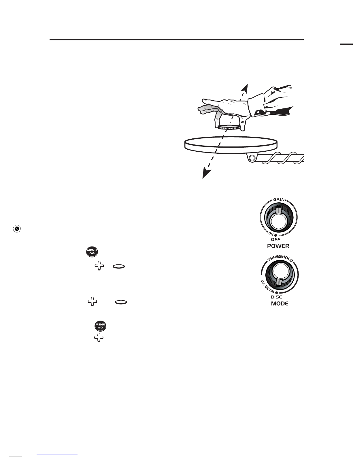
Pinpointing in Discrimination Mode:
1. Sweep over target in narrowing side-to-side pattern.
2. Take visual note of spot on ground where “beep” occurs.
3. Step 90° to the side of the target.
4. Sweep searchcoil over same area, at 90° to 1st sweep pattern.
5. This pinpoints the target location with an “X.”
I. Supplies Needed
• a Nail • a Zinc Penny (dated after 1982)
• a Nickel • a Quarter
II. Position the Detector
a. Place the detector on a table,
with the searchcoil hanging over
the edge. Or better, have a friend
hold the detector, with the
searchcoil off the ground.
b. Keep the searchcoil away from
walls, floors and metal objects.
c. r emove watches, rings and
jewelry.
d. Turn off fluorescent lights,
appliances and cell phones
whose electromagnetic emissions may
cause interference.
e. Pivot the searchcoil back.
III. Click on power with the left knob. Set the Gain at the 12:00
position for this demonstration.
IV. Click the right knob to the left to enter DISC setting.
V. Press until “v OLUMe ” is highlighted on display.
a. Press or until number on display is 12.
b. Wave the nail over the searchcoil. Notice volume.
c. Wave a coin over the searchcoil. Notice louder volume.
d. e nter the menu/volume control again.
Use and to change volume as you wave nail over
searchcoil. Notice the volume changing.
VI. a. Set volume at 20. Wave the nail over the searchcoil.
b. Press until DISC is highlighted on display.
c. Press repeatedly, while continuing to wave the nail.
The nail will be discriminated out. The Target-ID at which it is eliminated
depends on the size of the nail.
VII. Wave each object over the searchcoil.
Sweep coins flat and parallel to the searchcoil. This is how
you will usually find them buried.
a. Notice the 2-digit Target-IDs for each object.
b. Motion is required.
Objects must be in motion over the searchcoil to be
detected in this mode.
QUICK-START DEMONSTRATION
Quick-Start Demo continued on next page

9
IX. Click the MODE knob to the right.
The detector is now in the ALL MeTAL Mode
a. Keep GAIN set at the 12:00 position
b. r otate the THr e SHOLD knob slowly from the far counterclockwise
position to the full clockwise position.
Notice these attributes of the THr e SHOLD control, with no metal
over the searchcoil.
i. at low settings you will hear no sound
ii. at mid-scale, there will be a transition point from no sound to
a barely audible, choppy sound.
iii. at full scale you will hear a loud, constant tone. It may also have
an irregular or choppy sound, as a result of electromagnetic
interference emitted from other electrical devices.
USE WITH HEADPHONES
(not included)
The F19™ is equipped with a 1/4” headphone jack. Any headphones with a 1/4”
stereo plug will work; headphones with a mono plug will not work. Using
headphones extends battery life, and also prevents the sounds from bothering
bystanders. It also allows you to hear subtle changes in the sound more clearly,
particularly if searching in a noisy location. If gold prospecting, gold nuggets are
often very small, so closely monitoring changes in sound using headphones will
improve your gold prospecting results. For safety reasons, do not use headphones
near traffic or where other dangers are present. This device is to be used with
interconnecting cables/headphone cables shorter than three meters (ten feet).
VIII. Press-and-hold and hold the nickel over the searchcoil
a. Notice that motion is not required.
A motionless object induces a hum.
b. Notice the variable pitch & volume hum.
c. Move the nickel closer to and farther away from the searchcoil.
Notice the changing “depth” values.
QUICK-START DEMONSTRATION

10
ELECTROMAGNETIC INTERFERENCE (EMI)
You are likely to encounter electromagnetic interference (e MI) when using your F19™
metal detector. It is important that you recognize eMI and take appropriate measures
to deal with it. This will prevent you from giving up on a worthwhile search site, or from
returning a properly functioning detector for repair.
Symptoms of Electromagnetic Interference
eMI can cause a metal detector to chatter spontaneously, to lose sensitivity for no apparent
reason, or to cause a periodic wobbly audio sound. What you hear will depend on what
operating mode you are using, the detector’s settings, and the source of the electrical
interference. The most common manifestation is spontaneous chatter.
All metal detectors are susceptible to e MI, but they vary in what kinds of interference
affect them. In a given environment some metal detectors may be affected by eMI
whereas others may not.
Common sources of Electromagnetic Interference
Common sources of eMI include: overhead electric power lines, underground power lines,
other metal detectors, telephone lines carrying electronic data, computer systems, electric
fences, old Cr T-based televisions, cell phones, CB and emergency communication
radios, thunderstorms, fluorescent lights, metal vapor lamps, military aircraft with electronic
warfare countermeasures turned on, electric motors, v LF military communications systems
and automobile ignition systems. At home, in a store, or in an urban environment, there
may be several different sources of interference present simultaneously.
All metal detectors generate a certain amount of internal electronic noise. The F19™ is
specifically designed to enable you to work into the noise. experienced users, striving
for maximum depth, often adjust the machine to search with a constant audible
background sound, and then listen through that noise for the sound of real targets.
Stricter regulations in recent years have cut down on interference from electric light
dimmers and auto ignition systems. However there has also been a proliferation of
v LF-UHF wireless communication systems (cell phones, Bluetooth, Wi-Fi, etc.), which
often affect metal detectors. Overall, the potential for electromagnetic interference is
greater than it was just a few years ago.
Modern high-end metal detectors are a lot more sensitive than older units; this also
increases your detector’s vulnerability to eMI beyond what you may be accustomed to
with an older detector. Metal detectors are by their nature designed to detect magnetic
fields, and electric current always produces magnetic fields.
Coping with Electromagnetic Interference
The primary reason metal detectors provide a sensitivity (gain and/or threshold) control,
is so that users can reduce sensitivity in order to eliminate response to electrical
interference. Some users are reluctant to reduce sensitivity out of fear of losing depth.
At reduced sensitivity settings, you may lose some depth, but at least you can still
search. The Gain and Threshold knobs control the sensitivity and are your first
line of defense against EMI. The Threshold control only applies to the All Metal Mode.
THE BASICS OF METAL DETECTING
A hobby metal detector is intended for locating buried metal objects. When
searching for metals, underground or on the surface, you have the following
challenges and objectives:
1. Ignoring signals caused by ground minerals.
2.
Ignoring signals caused by metal objects that you do not want to find,
such as pull-tabs.
3. Identifying a buried metal object before you dig it up.
4. estimating the size and depth of objects to facilitate digging them up.
5. eliminating the effects of electromagnetic interference from other
electronic devices.
Your F19™ metal detector is designed with these points in mind.
1. Ground Minerals
All soils contain minerals. Signals from ground minerals can interfere with
the signals from metal objects you want to find. All soils differ, and can
differ greatly, in the type and amount of ground minerals present. You
therefore want to calibrate the detector to the specific ground conditions
where you are hunting. The detector incorporates both automated and
manual ground balancing features which will eliminate false signals from
most types of soils. To maximize the detector’s target identification
accuracy and depth of detection, use the Gr OUND Gr AB
®
COMPUTe r IZe D Gr OUND BALANCING function to calibrate the
detector to the ground where you are searching. See the section on
Gr OUND BALANCING for details.
The Basics continued on next page

1130
2. Trash
If searching for coins, you want to ignore items like aluminum foil, nails and
pull-tabs. These undesirable items are generally identified toward the lower
end of the 1-99 scale. You can listen to the sounds of all objects detected,
and decide on what you want to dig up. Or you can eliminate unwanted
metals from detection by using the DISCr IMINATION feature.
3. Identifying Buried Objects
Different types of metals are classified along the arc at the top of the screen
on a 1-99 scale from left to right. A 2-digit numerical reading is also
provided in the middle of the display for more precise target identification in
Discrimination Mode.
4. Size and Depth of Buried Objects
When using the detector in the motion DISC Mode, the relative depth of an
object is displayed to the left of the display over the SIGNAL strength
indicator. A more accurate depth reading is available using PINPOINT.
Pinpoint displays estimated target depth, in inches. Pinpoint does not
require the searchcoil to be in motion to detect metals. The ability to hold
the searchcoil motionless over the target also aids in tracing an outline of
the buried object, or in pinpointing the exact location of the object using
techniques described in the pinpointing section of this manual.
5. Electromagnetic Interference (EMI)
electromagnetic interference (e MI) can cause a metal detector to chatter
spontaneously, to lose sensitivity for no apparent reason, or to cause a
periodic wobbly audio sound. Common sources of eMI include power
lines, electronic communication equipment such as cellphones, fluorescent
lamps, military electronics such as radar, other metal detectors and
computer equipment.
Your first line of defense against eMI is to reduce the Gain and/or
Threshold. In areas with heavy eMI, operating at reduced sensitivity levels
will result in the loss of some depth, but at least the metal detector will be
usable.
See the section on eLe CTr OMAGNeTIC INTe r Fer eNCe for a more
thorough explanation of e MI and how to manage it.
THE BASICS OF METAL DETECTING
12
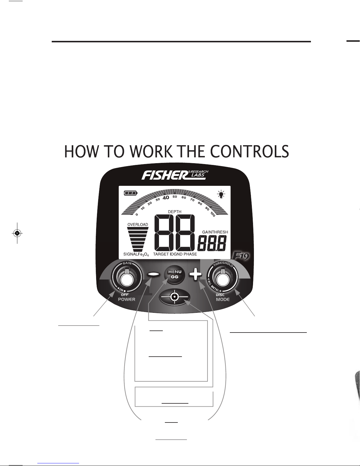
OPERATION & CONTROLS
VOLUME
V-BREAK
NOTCH WIDTH
DISCGND BAL
ON/OFF/GAIN:
• Click ON/OFF
• In DISC Mode rotate
to change GAIN
(sensitivity) from
1 to 100
• In ALL METAL Mode
rotate to change
GAIN from 5 to 100
in steps of 5
• In DISC Mode press
to cycle through
menu options
• In ALL METAL Mode
press-and-hold
while bobbing coil
to set ground balance
Press-and-hold to
activate PINPOINT feature
In DISC Mode:
Change setting of active menu option
In ALL METAL Mode:
Change Ground Balance setting from 0 to 99.9
MODE SELECTION/
THRESHOLD CONTROL
• Click left to operate
in Discrimination
Mode
• Click to right to
operate in ALL METAL
Mode.
• Rotate knob in
ALL METAL Mode to
change THRESHOLD from
-40 to 40
POWERING UP
NOTE: Immediately after powering on, your detector's unique 10-digit serial
number is displayed once on the LCD. Two digits are displayed at a time; five
2-digit numbers are displayed in sequence. This 10-digit serial number is the
same serial number imprinted on the label inside the battery compartment.
• Click the left knob clockwise to turn the detector ON.
• After clicking the knob on, continued clockwise rotation will increase the
“sensitivity” in DISC Mode or the “GAIN” in ALL Me TAL Mode.
• We suggest keeping the GAIN below 70 until you become familiar with
the detector’s operation.
Searching for coins and relics at Civil War or ghost town sites often
means detecting in heavy concentrations of iron and dealing with crop-stubble
or forest ground clutter.
The F19 can handle the toughest ground mineralization, capable of
ground balancing all the way to salt. With its fast retune speed and biaxial
searchcoil, the F19 creates superb target separation with impressive depth.
The 10” elliptical coil is ideal for working between brush, rocks and debris
commonly found at old abandoned sites. An expanded 40-point iron ID range
helps differentiate between larger iron objects and smaller nails and pieces.
With FeTone
be lowered separate from the volume level of non-ferrous targets, allowing
desired targets to be heard much easier.
The fine-tune adjustable Notch Width can be used to target specific
unwanted items, such as shell casings or bottle caps, and the enhanced
v -Break
®
, our v ariable Tone Breakpoint, allows the user to further customize
the detector’s settings to get unique audio on specific Target-ID ranges.
Combined, the Notch Width and v -Break features create endless variations
for fine tuning the detector to meet exact hunting needs.
An adjustable back-light on the display allows for hunting in low-light
conditions.
RELIC HUNTING
 Loading...