


Full Panel Detachable
FM Stereo/AM Receiver
Compact Disc Player
ISO Mounting with Removable Trim Ring
GB
E

SANYO MOBILE AUDIO
MODEL ECD-T1820
LIMITED WARRANTY
OBLIGATIONS
In order to obtain warranty service, the product must be delivered to and picked up from an Authorized Sanyo Factory Service Center at the
user's expense, unless specifically stated otherwise in this warranty. The names and addresses of Authorized Sanyo Service Center may be
obtained by calling the toll-free number listed below.
For product operation, authorized service center referral, service assistance or problem resolution, call
For accessories and/or parts not available from an authorized dealer, call
THIS WARRANTY IS VALID ONLY ON SANYO PRODUCTS PURCHASED AND USED IN THE UNITED STATES OF
AMERICA. THIS WARRANTY APPLIES ONLY TO THE ORIGINAL RETAIL USER, AND DOES NOT APPLY TO PRODUCTS USED FOR ANY INDUSTRIAL, PROFESSIONAL OR COMMERCIAL PURPOSE. THE ORIGINAL DATED BILL
OR SALE OR SALES SLIP MUST BE SUBMITTED TO THE AUTHORIZED SANYO SERVICE CENTER AT THE TIME
WARRANTY SERVICE IS REQUESTED.
Subject to the OBLIGATIONS above and EXCLUSIONS below, SANYO FISHER COMPANY(SFC) warrants this SANYO product against defects in materials and workmanship for the periods specified below. SFC will repair or replace (at its option) the product and any of its parts
which fail to conform to this warranty. The warranty period commences on the date the product was first purchased at retail.
This warranty does not cover (A) the adjustment of customer-operated controls as explained in the appropriate model's instruction manual, or
(B) the repair of any product whose serial number has been altered, defaced or removed.
This warranty shall not apply to the cabinet or cosmetics parts, knobs or routine maintenance.
This warranty does not apply to uncrating, setup, installation, removal of the product for repair or reinstallation of the product after repair.
This warranty does not apply to repairs or replacements necessitated by any cause beyond the control of SFC including, but not limited to,
any malfunction, defect or failure caused by or resulting from unauthorized service or parts, improper maintenance, operation contrary to furnished instructions, shipping or transit accidents, modification or repair by the user, abuse, misuse, neglect, accident, incorrect power line voltage, fire, flood or other Acts of God, or normal wear and tear.
The foregoing is in lieu of all other expressed warranties and SFC does not assume or authorize any party to assume for it any other obligation
or liability.
THE DURATION OF ANY WARRANTIES WHICH MAY BE IMPLIED BY LAW (INCLUDING THE WARRANTIES OF
MERCHANTABILITY AND FITNESS) IS LIMITED TO THE TERM OF THIS WARRANTY. IN NO EVENT SHALL SFC BE
LIABLE FOR SPECIAL, INCIDENTAL OR CONSEQUENTIAL DAMAGES ARISING FROM OWNERSHIP OR USE OF
THIS PRODUCT, OR FOR ANY DELAY IN THE PERFORMANCE OF ITS OBLIGATIONS UNDER THIS WARRANTY
DUE TO CAUSES BEYOND ITS CONTROL. SOME STATES DO NOT ALLOW LIMITATIONS ON HOW LONG AN IMPLIED WARRANTY LASTS AND/OR DO NOT ALLOW THE EXCLUSION OR LIMITATION OF CONSEQUENTIAL DAMAGES, SO THE ABOVE LIMITAIONS AND EXCLUSIONS MAY NOT APPLY TO YOU.
THIS WARRANTY GIVES YOU SPECIAL LEGAL RIGHTS. YOU MAY HAVE OTHER RIGHTS, WHICH VARY FROM
STATE TO STATE.
CUSTOMER INFORMATION 1-800-421-5013
Weekdays 8:00 AM - 5:00 PM Pacific Time
PARTS ORDER INFORMATION 1-800-726-9662
Weekdays 8:00 AM - 5:00 PM Pacific Time
LABOR PARTS
1 YEAR 1 YEAR
EXCLUSIONS
ATTENTION
For your protection in the event of theft or loss of this product, please fill in the information below for your own personal records.
Model No. Serial No.
Date of Purchase Purchase Price
Where Purchased
WARNING :
TO PREVENT FIRE OR SHOCK HAZARD, DO NOT EXPOSE THIS APPLIANCE TO RAIN OR MOISTURE.
(Located on back or bottom side of unit)
-1-

English
CONTENTS
COMPACT DISC CARE. . . . . . . . . . . . . . . . . . . . . . . . . . . . . . . . . . . . . . . . . . . . . . . . . . . . . . . 3
DIGITAL DISPLAY. . . . . . . . . . . . . . . . . . . . . . . . . . . . . . . . . . . . . . . . . . . . . . . . . . . . . . . . . . . 5
DETACHABLE FRONT PANEL. . . . . . . . . . . . . . . . . . . . . . . . . . . . . . . . . . . . . . . . . . . . . . . . . 6
GENERAL OPERATION . . . . . . . . . . . . . . . . . . . . . . . . . . . . . . . . . . . . . . . . . . . . . . . . . . . . . . 7
RADIO OPERATION . . . . . . . . . . . . . . . . . . . . . . . . . . . . . . . . . . . . . . . . . . . . . . . . . . . . . . . . . 9
CD OPERATION . . . . . . . . . . . . . . . . . . . . . . . . . . . . . . . . . . . . . . . . . . . . . . . . . . . . . . . . . . . 11
AUX OPERATION . . . . . . . . . . . . . . . . . . . . . . . . . . . . . . . . . . . . . . . . . . . . . . . . . . . . . . . . . . 13
ERROR SIGNS . . . . . . . . . . . . . . . . . . . . . . . . . . . . . . . . . . . . . . . . . . . . . . . . . . . . . . . . . . . . 14
CLOCK. . . . . . . . . . . . . . . . . . . . . . . . . . . . . . . . . . . . . . . . . . . . . . . . . . . . . . . . . . . . . . . . . . . 15
HINTS FOR PROPER AND SAFE OPERATION . . . . . . . . . . . . . . . . . . . . . . . . . . . . . . . . . . 16
TROUBLESHOOTING. . . . . . . . . . . . . . . . . . . . . . . . . . . . . . . . . . . . . . . . . . . . . . . . . . . . . . . 17
ACCESSORIES AND HARDWARE. . . . . . . . . . . . . . . . . . . . . . . . . . . . . . . . . . . . . . . . . . . . . 18
INSTALLATION . . . . . . . . . . . . . . . . . . . . . . . . . . . . . . . . . . . . . . . . . . . . . . . . . . . . . . . . . . . . 18
UNIT REMOVAL . . . . . . . . . . . . . . . . . . . . . . . . . . . . . . . . . . . . . . . . . . . . . . . . . . . . . . . . . . . 21
ELECTRICAL CONNECTIONS . . . . . . . . . . . . . . . . . . . . . . . . . . . . . . . . . . . . . . . . . . . . . . . . 22
LINE OUT CONNECTIONS. . . . . . . . . . . . . . . . . . . . . . . . . . . . . . . . . . . . . . . . . . . . . . . . . . . 23
SPECIFICATIONS . . . . . . . . . . . . . . . . . . . . . . . . . . . . . . . . . . . . . . . . . . . . . . . . . . . . . . . . . . 24
NOTE
This equipment has been tested and found to comply with the limits for a Class B digital device,
pursuant to Part 15 of the FCC Rules. These limits are designed to provide reasonable protection
against harmful interference in a residential installation. This equipment generates, uses, and can
radiate radio frequency energy and, If not installed and used in accordance with the instructions, may
cause harmful interference to radio communications. However, there is no guarantee that interference
will not occur in a particular installation. If this equipment does cause harmful interference to radio or
television reception, which can be determined by turning the equipment off and on, the user is
encouraged to try to correct the interference by one or more of the following measures:
- Reorient or relocate the receiving antenna.
- Increase the separation between the equipment and receiver.
- Connect the equipment into an outlet on a circuit different from that to which the receiver is connected.
- Consult the dealer or an experienced radio/TV technician for help.
CAUTION
• This unit is designed to operate on 12 volts DC, NEGATIVE ground electrical systems only.
• When fuse replacement is necessary, use only a 15 amp fuse. Do not replace with a higher rated fuse.
If the fuse blows often, carefully check all electrical connections for any short circuits and have your
car's voltage regulator checked also.
• Do not install the unit where it will be exposed to direct sunlight or hot air discharged from the car heater.
• Do not expose the unit to water or moisture.
• To avoid damaging the unit, never insert anything other than a compact disc into the disc slot.
• This unit should not be adjusted or repaired by anyone except qualified service personnel.
If servicing is required, return the unit to an authorized SANYO mobile audio dealer.
• Use of controls or adjustments or performance of procedures other than those specified herein may
result in hazardous radiation exposure.
• Changes or modifications not expressly approved by Sanyo may void the user's authority to operate
this equipment.
-2-

COMPACT DISC CARE
Dirt, dust, scratches and warpage can cause a deterioration in the sound or intermittent skipping some tracks
during play.
abel Side
• This unit has been designed to play compact
bearing the identification logo shown on the left.
Discs bearing other types of identification logos
may not play properly.
• Playback may not be possible due to the
characteristics of the CD recorder or the CD-R/RW
used, or due to scratches or dirt on the CD.
• For some CD-R/RWs, depending on the quality
of their recording or storage media used, playback
may not be possible due to deterioration of
recorded of material.
• Do not use non-conventional discs such as
heart-shaped, octagonal discs, etc.
The player could be damaged.
• Fingerprints and dust should be carefully wiped
from the signal surface of the disc (glossy side) with
a soft cloth.
Wipe in a straight motion from the inside to the
outside of the disc. Unlike conventional records,
the compact disc has no grooves to collect dust and
debris. Small dust particles will have no effect on
reproduction quality.
discs
• Do not insert a disc which is cracked into the unit.
• Do not apply paper or write anything on the disc.
• To prevent warping the disc, do not expose it to
direct sunlight, high humidity or high temperatures
for extended periods.
-3-
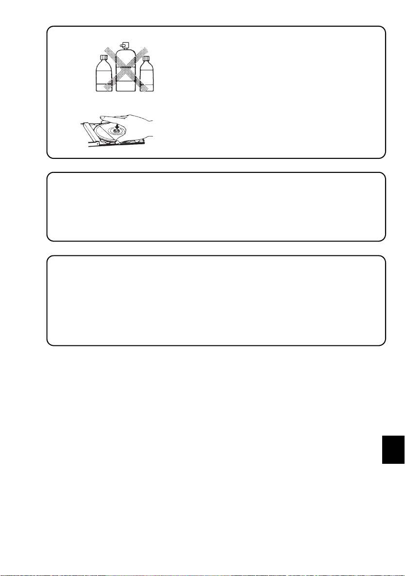
• Never use chemicals such as record cleaning
sprays, antistatic sprays or fluids, benzene or
thinner to clean compact discs. These chemicals
will permanently damage the plastic surface of
the disc.
• When not using the disc player for extended
Benzene Thinner Cleaning spray
periods, remove the compact disc and return it to
the plastic storage case. This will protect the disc
from dust and exposure to the sun.
• Mixed-mode CDs
This product can only play audio tracks on mixed-mode CDs.
The initial track contains non-audio data, and so it does not produce any sound.
Playback will start from the next track.
(Mixed-mode CDs are CDs which contain both non-audio data and audio tracks.)
• CDs containing copy control protection technology.
It is possible that some CDs with copy control protection (added to prevent computer
duplication) may not play on this unit.
This is due to the CD with copy control protection not conforming to CD standards and is
not due to a malfunction of this unit.
If there are any problems playing a CD with copy control protection, consult the store where
the CD was purchased.
-4-
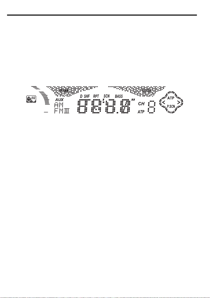
DIGITAL DISPLAY
-5-
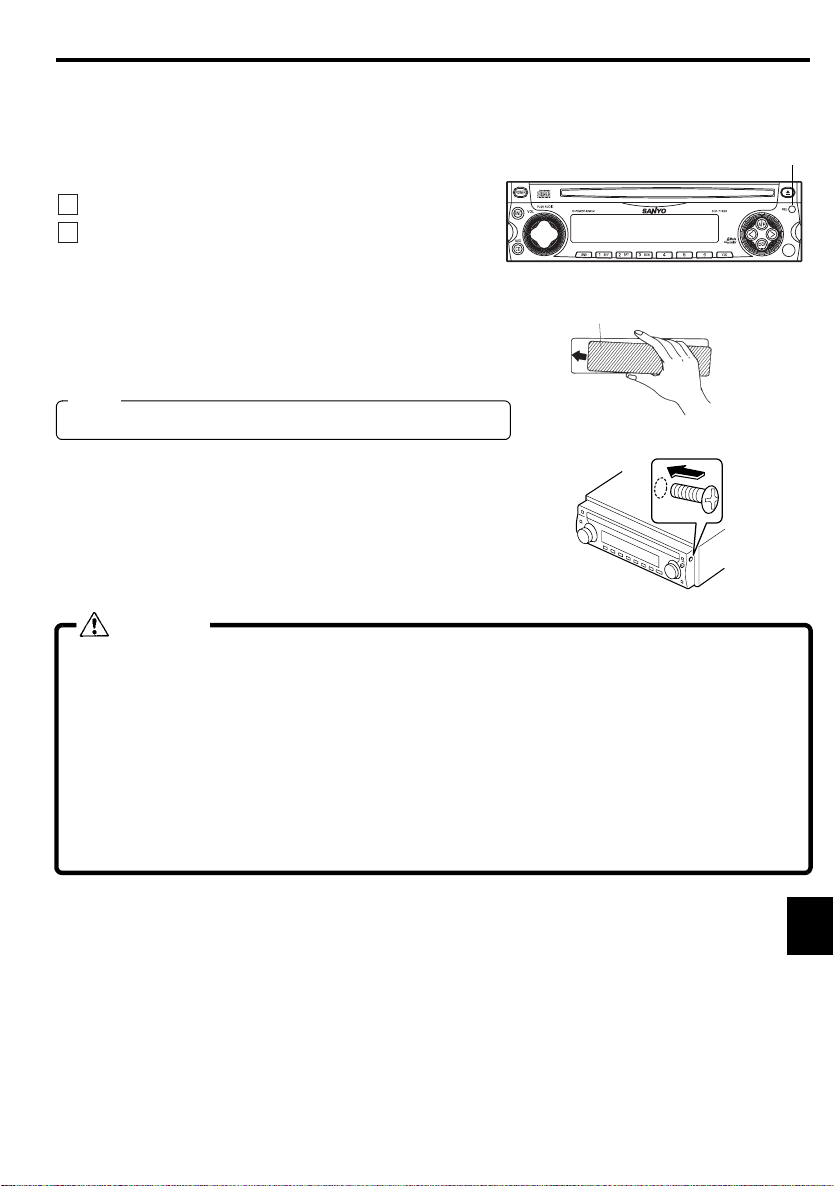
DETACHABLE FRONT PANEL
FRONT PANEL
The front panel is designed to be removable for antitheft purposes.
It is recommended that you remove and carry the front panel with you when you leave your car.
A carrying case is provided with the unit for this purpose.
HOW TO DETACH THE FRONT PANEL
1
Press the release knob (REL) to release the front panel.
2
Pull the entire panel to remove it from the unit.
HOW TO REPLACE THE FRONT PANEL
Align the left side of the panel with the stopper,
and then push the right side of the panel into the
unit until it clicks.
Note
The unit will not operate if it is installed incorrectly.
FRONT PANEL FIXING
The front panel can be installed so that it cannot be removed
to prevent theft or loss. Using the screw included with the
accessory kit, install it to the right side of the front panel.
RELEASE KNOB
CAUTION
• Do not attempt to remove the panel in a manner other than that described above.
• When installing the panel, do not force it into the unit.
• Do not touch the connection terminals of the panel or the unit. It may cause poor
contact.
• Use a clean, dry cloth when cleaning the terminals.
• Keep the panel out of direct sunlight and high temperatures.
• Prevent the panel from coming into contact with benzene, thinner, or insecticides.
• Do not drop the panel.
• Do not attempt to remove the radio front panel that takes your attention away from safety
driving you vehicle.
-6-
GENERAL OPERATION
TURNING THE POWER ON
Install the front panel and press the POWER button when ACC is on.
TURNING THE POWER OFF
Press the POWER button to stop the current operation.
The button dims when the power is off (ACC on).
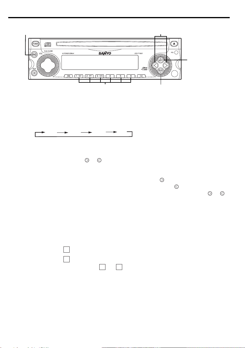
ELECTRONIC CONTROLS
Push the AUDIO button , then Push the AUDIO button to select the audio functions as shown in the
table below.
Turn the VOL knob to adjust the selected function ; bass, treble, balance, fade, or volume.
MODE
bAS(bass)
TRE(treble)
bAL(balance)
FAd(fader)
V(volume)
........................................ 1
...................................... 1
......................................... 2
Turn left (Min)
Down -5
Down -5
Left L9
Rear R9
Down 0
Turn right (Max)
UP +5
UP +5
Right R9
Front F9
UP 35
SOUND EFFECT BUTTON
Press the SND Button for less than 1.5 second.
Each time the button is pressed, the function changes as shown below.
1 FLA (FLAT) 2 ROC (ROCK) 3 CLA (CLASSIC) 4 POP (POPS) 5 JAZ (JAZZ) 6 HIP (HIP HOP)
......................................... 3
-7-
BASSXPANDER
Press the SND button for more than 1.5 second to switch ON/OFF of the BASS mode. When the BASS
mode is on, “bASS” is displayed and the bass enhances.
........................................................ 3
RADIO SELECTION BUTTON (BND)
Press the BND button to switch from CD player mode to radio.
Each time the button is pressed, the function changes as shown below.
FMI FMII AM
FMIII
CD OR AUX SELECTION BUTTON (CD/AUX)
Press the CD/AUX button to switch from radio mode to AUX or CD player mode.
CLOCK BUTTON (CLK)
Press the CLK button to switch between the clock and audio display. When an audio function is
performed while the time display is selected, the audio display will appear for 5 seconds, then the display
will return to the time mode.
............................................. 6
TO CANCEL THE BEEP TONES
1
Turn off the power by depressing the POWER button .
2
To cancel all beep tones, press the POWER button and the button simultaneously for more than
3 seconds and then "bP : oF" is displayed.
3
To turn on the beep tones again, perform the same procedure. The beep tones are set and "bP : on" is
displayed.
DEMO MODE ON/OFF
1
Turn off the power by depressing the POWER button .
2
To turn ON/OFF the demo mode, press the POWER button and the button simultaneously for
more than 3 seconds.
............................................... 1, 8
........................... 4
............... 5
................................. 1, 7
DEMO ON : Demo is displayed.
DEMO OFF : Display is OFF.
(DEFAULT : DEMO ON)
-8-
RADIO OPERATION
1
2
4
3
SELECTING RADIO MODE
Press the BND button to switch from CD player or AUX mode to the radio.
Each time the BND button is pressed, the selected band changes as shown below.
FMI FMII AM
RADIO TUNING
• Automatic tuning ............Press the or button for more than 0.5 second until it beeps twice if the
•
Manual tuning ................ To select higher frequency stations, press the button for less than 0.5
........................................................ 2
beep tones are on. When the button is released, the system will start automatic
tuning and stop at the next receivable station.
second.To select lower frequency stations, press the button for less than 0.5
second. To quickly scan up or down in frequency, press and hold the or
button. Release the button when the display approaches the desired frequency,
then press and release the button repeatedly until the desired frequency is
displayed.
........................................ 1
FMIII
5
STORING PRESET STATIONS
The preset buttons can be used to store 6 stations in each band (FMI, FMII, FMIII and AM) for convenient
access to your favorite stations.
• Programming stations
• Quick tuning.................... Select the desired band, then press one of the six preset buttons.
1
.....
Select the desired band, then tune in the station you want to store in memory.
2
Press and hold one of the preset buttons for more than 2 seconds.
Repeat steps
................................... 3
1 22
and to program additional stations.
-9-

ATP (AUTO TRAVEL PRESET) OPERATION
The Auto Travel Preset function searches for and memorizes the 6 strongest stations in one of the two
bands (FM, AM) in the order of signal strength.
This feature is useful when you are driving in an unfamiliar location and want to memorize local stations
without changing the standard preset stations.
A total of 12 stations (6 FM and 6 AM) can be programmed.
•
To set the stations
•
Quick Tuning of ATP Stations
• To scan programmed stations............. See “PRESET-SCAN-BUTTON OPERATION”.
...............................
.................
1
Select the desired band.
2
Press and hold the ATP button for more than 2 seconds.
“ATP” appears in the display.
When the stations have been memorized, scanning stops and the
strongest station is selected.
1
Select the desired band.
2
Press the ATP button if the “ATP” indicator does not appear in
the display.
3
While ATP is illuminated, press the ATP button and the unit
seeks ATP1-6. If there is no preset ATP, - 0 - appears in the
display.
................ 4
Notes
•
If no station can be received, “- 0 -” appears in the display.
•
If fewer than 6 stations can be received, the system will memorize as many stations as
possible, then select the strongest one.
•
If ATP mode is selected in FMII, FMIII band, FM ATP mode is selected.
To cancel the ATP, press the BND button . When ATP is canceled, the ATP indicator disappears and ATP
mode is canceled.
PRESET-SCAN-BUTTON OPERATION
This function scans each of the preset stations stored in the selected band (both manual preset and
auto travel presets).
1
Select the desired band or ATP mode.
Press the BND button for FMI, FMII, FMIII or AM. Press the ATP button to select the ATP mode.
2
Press the P.SCN button . The system will select and receive each preset station for ten-second.
3
To stop scanning and retain the station currently selected, press the P.SCN button again during this
ten-second period.
-10-
........................ 1, 4, 5
CD OPERATION
1
2
3 6 7 8 9 5 4
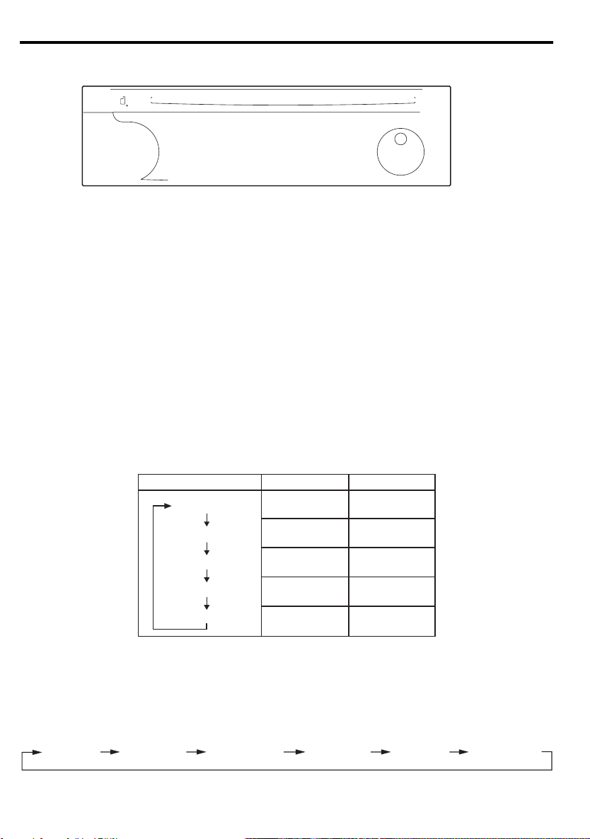
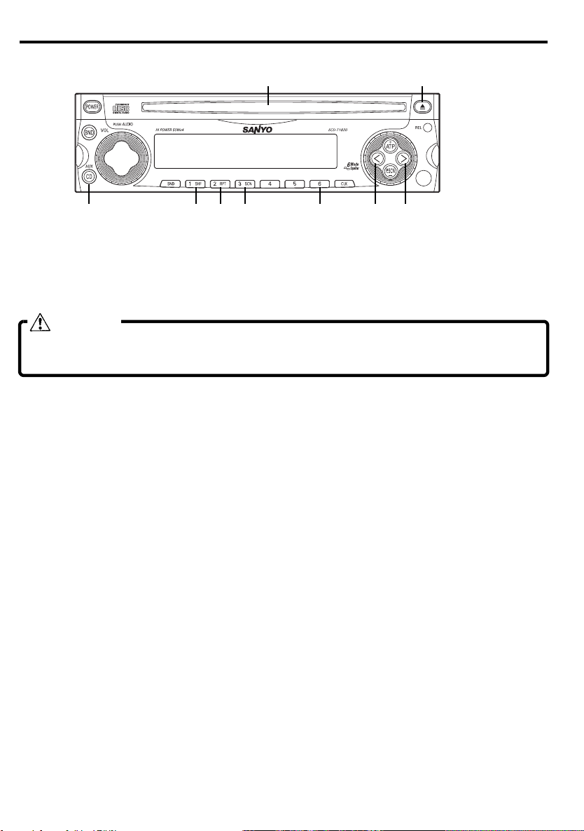
LOADING AND EJECTING THE CD
Insert a disc into the CD slot and the CD player will start playing.
Press the eject button to eject a disc.
CAUTION
• If the unit is already loaded with a CD, please do not attempt to insert another disc,
which may result in damage to both of the discs and the unit.
SWITCHING TO CD MODE
Press the CD button to switch from radio or AUX mode to CD player mode.
When the CD mode is switched on while a disc is loaded, play resumes from the point at which play was
stopped.
When the entire disc has played, the unit returns to the first track and play resumes.
The CD player continues playing the disc until the POWER button is pressed, the other mode is selected, or
the disc is ejected.
......................................... 3
............................ 1, 2
-11-
SKIPPING TRACKS
Press the button to skip to the beginning of the next track.
Press the button to skip to the beginning of the track currently playing.
Press the button twice to skip to the beginning of the previous track.
Press and hold the or button for more than 0.5 seconds to search quickly
(with sound) in the forward or reverse direction.
When the button is released, the CD resumes normal play.
................................................... 4, 5
SHUFFLE MODE
This function plays the tracks on a CD in random order.
Press the SHF button to begin shuffle play. The SHF indicator lights.
Press the or button twice to select another random track.
To cancel this mode, press the SHF button again or eject the CD.
Notes
If a disc is already loaded under the following conditions, shuffle play will resume
from the point at which play was stopped:
•
If the vehicle ignition is turned off, then on again.
•
If the power is switched off, then on again with the POWER button.
REPEAT MODE
Press the RPT button to play the current track repeatedly. The RPT indicator lights.
To cancel this mode, press the RPT button again or eject the CD.
Notes
If a disc is already loaded under the following conditions, repeat play will resume:
•
If the vehicle ignition is switched off, then on again.
•
If the power is switched off, then on again with the POWER button.
....................................................... 6
......................................................... 7
SCAN MODE (PLAYING THE BEGINNING
OF EACH TRACK)
This function plays the first 10 seconds of each track sequentially.
Press the SCN button to begin the scan mode. The SCN indicator lights.
To cancel this mode, press the SCN button again.
Note
Scan mode will be canceled when the vehicle ignition is turned off, or when the disc
is ejected.
..................................................... 8
SWITCHING BETWEEN THE TRACK NUMBER AND
CD PLAY TIME DISPLAYS
Each time the preset button "6" ➈ is pressed, the display switches between the track number display and the
CD play time display.
When the preset button "6" ➈ is pressed while the track number is displayed, "TRoF" is displayed, and the
display switches to the play time display.
When the preset button "6" ➈ is pressed while the CD play time is displayed, "TRon" is displayed, and the
display switches to the track number display.
......................................... 9
-12-

AUX OPERATION
Auxiliary mode allows for playing of an auxiliary audio source that is connected by a
commercial auxiliary cord to the AUX IN jack of this unit.
AUX CONNECTION
Connect the auxiliary audio source to the AUX IN jack of this unit with a commercial auxiliary cord.
SELECTING AUX MODE
Press the CD/AUX button to switch from radio or CD player mode.
Pressing the button will change the mode as explained in section “CD OR AUX SELECTION BUTTON (CD/
AUX)” in page 8.
CAUTION
• Before connection, set the volume for this unit to “ 0
auxiliary audio source within a range that will not cause distortion.
Notes
Noise may be emitted if the following actions are performed. Be sure to turn off this unit or
switch to another mode before performing these actions.
•
The auxiliary audio source is turned off.
•
The auxiliary cord is connected to or disconnected from the auxiliary audio source or the
AUX IN jack of this unit.
Notes
•
Please consult with an authorized SANYO mobile audio dealer where this unit was bought
for details about whether a given auxiliary audio source can be connected and the proper
auxiliary cord to use.
•
The volume and tone controls of the auxiliary audio source can be adjusted on this unit.
................................................... 1
............................................ 2
and also keep the volume of the
”
-13-
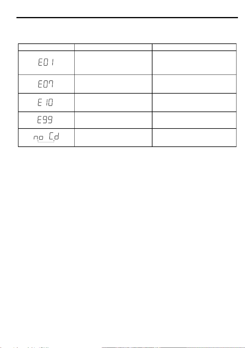
ERROR SIGNS
CD Player
If a problem should occur while operating the built-in CD player, one of the following error signs
may be displayed:
Error Sign
Cause
Press the eject button.
Abnormal CD mechanism function.
The disc is dirty.
CD is inserted upside down.
Abnormal amplifier. Check the speaker line code.
Internal connection check error. Contact the place of purchase.
No disc in the player. Insert the disc.
Turn the power off and then on again.
If it is not corrected, contact the place
of purchase.
Clean the disc.
Insert the CD properly.
Remedy
-14-

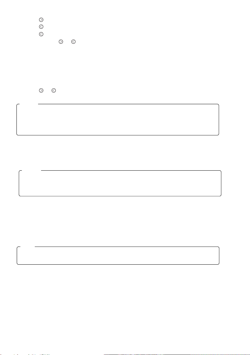
CLOCK
DISPLAY MODE CHANGE
The display on the unit can be changed by pressing CLK button . Press the CLK button to switch
between the clock and audio display. When a radio, tape and CD function is performed while the time display
is selected, the audio display will appear for 5 seconds, then the display will return to the time mode.
ADJUSTING THE TIME
To adjust the time, press the CLK button for more than 2 seconds. The time display blinks.
To adjust the minute, press the button .
To adjust the hour, press the button .
To advance the time rapidly, hold the or button continuously.
Press CLK button again to start the clock.
CLOCK RESET
Press CLK button for more than 2 seconds and the time display blinks. While blinking, press preset
button 6 to skip to the nearest half-hour as follows:
3:30
–
–
Example: 3:00
......................................................... 1, 4
3:29 3:00
3:59 4:00
......................................... 1
.............................................. 1, 2, 3
-15-

HINTS FOR PROPER AND SAFE OPERATION
•
Condensation
Moisture can condense on the optical lens of the CD player during humid or rainy days, or after the car
heater is turned on. If this occurs the disc player may not function properly. To remedy the situation,
remove the disc from the unit and wait approximately one hour. This should allow the moisture to
evaporate and restore normal operation.
•
Temperature Consideration
The unit may not operate correctly in extremely hot or cold temperatures. Avoid exposing the unit to
extremely high or low temperatures.
•
Interruptions in the sound (skipping)
When the car is driven on very rough surfaces, the sound from the CD player may skip and be interrupted.
This will not cause any damage to the disc or the player. If this occurs, wait for the road surface to
improve before using the CD player.
•
Safety
For safer driving, keep the volume at a moderate level to enable you to hear outside sounds (such as
emergency vehicle sirens).
•
Cleaning the unit
Clean the unit with a soft, dry cloth. Stains should be removed by wiping the surfaces with a soft cloth
immersed in lukewarm water and wrung dry. Never use strong chemicals or solvents. These will damage
the finish of the unit.
•
Disc care
When not using the disc player for extended periods, remove the compact disc and return it to the
plastic storage case. Do not leave a disc partially ejected from the player.
•
Servicing
Should a problem develop, do not open the unit or try to repair it yourself. If servicing is required, bring
the unit to a Sanyo Authorized Service Center.
-16-

TROUBLESHOOTING
Sometimes a simple operational error or a mistake in the wiring can appear to be a problem with the unit.
Before having the unit serviced, refer to the troubleshooting chart below.
Symptom Cause Solution
The compact disc does not play
when inserted into the unit.
No sound is coming out. The speaker code connection is
No power. The vehicle ignition is switched
The unit does not work properly
(Eject, Load, Play).
The sound from the CD player
skips.
No radio reception. The antenna cable is not
The radio does not stop on any
stations when automatic tuning
is used.
The volume control is turned
down.
The power connections are not
wired correctly.
imcomplete.
off.
The fuse is blown. Replace the fuse with another
The microcomputer has been
affected by electrical noise.
The road surface is rough. Wait for the road surface to
The unit is not mounted
securely.
The disc is defective. Try another disc. If it plays
The disc is dirty. Clean the disc as explained on
connected.
The signals are weak. Select a station using manual
Turn up the volume control.
Check the +12V and ground
connections.
Check the connection of the
speaker code, and press the
ON/OFF button.
Switch the ignition to the "ON"
or "ACC" position.
15A fuse.
Eject the disc, then insert it
again.
improve before playing a disc.
Install the unit securely.
properly, the first disc may be
defective.
pages 3-4.
Insert the antenna cable firmly
into the antenna jack on the
unit.
tuning.
-17-

ACCESSORIES AND HARDWARE
Mounting Bracket
(Half Sleeve) x 1
Removable Trim Ring
x 1
Rear Strap
(Brace) x 1
Unlock Levers
x 2
Screw M5 x 14
x 1
INSTALLATION
1. BEFORE INSTALLATION
When mounting the unit in a car, keep the unit as level as possible.
If the unit must be mounted at an angle, due to the design of the
vehicle, make sure the unit does not tilt by more than 30°.
Hex bolt M5 x 8
x1
Screw M2 x 8
x 1
-18-

2. ISO MOUNTING WITH REMOVABLE TRIM RING
When mounting the unit into a DIN-standard cutout (182 × 53 mm) in the dashboard or
console, attach the provided Removable Trim Ring to the unit.
182 mm
53 mm
REMOVABLE TRIM RING
3. INSTALLATION PROCEDURES
DASHBOARD
OR CONSOLE
HEX BOLT
REAR STRAP
(BRACE)
M5 x 14
182 mm
53 mm
DASHBOARD OR CONSOLE
AUDIO UNIT
MOUNTING BRACKET
(HALF SLEEVE)
REMOVABLE
TRIM RING
AUDIO UNIT
1. Insert the mounting bracket into the DIN-standard cutout (182 × 53 mm) in the dashboard or console.
2. Bend the mounting bracket stopper outward until the bracket fits snugly in the cutout.
3. Push the unit into the mounting bracket until it locks in place.
4. Secure the rear strap to the audio unit and vehicle dashboard.
-19-

4. Installation to TOYOTA/NISSAN Vehicles
Install the unit using the existing TOYOTA/NISSAN Mounting Bracket and Screws. Use mounting holes in
the unit chassis. "T" or "N" is engraved next to each mounting hole. Use "T" holes for Toyota vehicles and
"N" holes for Nissan vehicles.
TOYOTA/NISSAN
Mounting Bracket
Screw
Screw
CAUTION
ONLY USE M5 x 8 SCREW
(NOT INCLUDED WITH THIS
UNIT) AS ILLUSTRATED ABOVE.
USE OF ANY OTHER SCREW OR
HARDWARE MAY RESULT DAMAGE
TO HEAD UNIT.
-20-

UNIT REMOVAL
2
2
2
UNLOCK LEVERS
2
2
2
1. Insert the unlock levers into the slots on each side of the unit until they click into place.
Note
Take care not to insert the levers upside down.
2. While pressing the levers downward, pull the levers to remove the audio unit.
UNLOCK LEVERS
-21-

ELECTRICAL CONNECTIONS
1. ANTENNA SOCKET
4-speaker System
(White)
(White/Black)
(Gray)
(Gray/Black)
(Green)
(Green/Black)
(Violet)
(Violet/Black)
2. +12V Constant Power Supply (Yellow)
3. +12V Accessory/Switched (Red)
4. Ground Wire (Black)
5. Power Antenna (Blue/Red)
6. Amplifier Turn On (Blue/White)
Front Left
Speaker
Front Right
Speaker
Rear Left
Speaker
Rear Right
Speaker
ANTENNA
PLUG
CAUTION
• DO NOT connect any speaker wires to the metal body or chassis of the vehicle.
• DO NOT connect the speaker common (-) wires to each other.
• Connect each speaker wire directly to each speaker terminal.
• All speaker common (-) wires must remain floating.
Antenna socket
1
Insert the plug from the antenna installed in your vehicle into this socket. (If your vehicle has a dual
•
antenna system, a dual antenna to single antenna cable adaptor may be required.)
+12V Constant Power Supply (Yellow)
2
Connect this wire to the +12V power terminal which receives power continuously.
•
Connect to location drawing 10 A amperage or more.
•
+12V Accessory/Switched (Red)
3
Connect this wire to the terminal which receives power while the ignition switch is at ON or
•
ACCESSORY position.
If the ignition switch does not have an ACC position, connect this wire to a +12V
•
power terminal which receives power continuously. (Same as item 2.)
Connect to location drawing 100 mA amperage or more.
•
Ground wire (Black)
4
Connect this wire to the vehicle chassis.
•
Power Antenna (Blue/Red)
5
Connect this wire to the control terminal of a Power Antenna.
•
When not using a Power Antenna, this wire is not connected.
•
Amplifier Turn On (Blue/White)
6
Connect this wire to an external amplifier.
•
When not using an external amplifier, this wire is not connected.
•
-22-

Notes
• When using a two-speaker installation, the Green, Green/Black, Violet, Violet/Black wires,
which are used for a four-speaker installation, are not used. The ends of these wires must
be covered with electrical tape to prevent them from shorting to the unit or the vehicle chassis.
• When using a two-speaker installation, set the
FADER control to the center position.
• When fuse replacement is necessary remove
the blown fuse by using pliers.
Then install the new 15 amp. fuse.
Fuse 15A
NG OK
Burnt
LINE OUT CONNECTIONS
The unit has a line output terminals. You can use a separate amplifier to upgrade your system.
•
RCA Line-out Jacks (For Speakers)
Connect a patch cable (not supplied) from the White (left channel) and Red (right channel) RCA line output
•
jacks to the line input terminals of the external amplifier.
-23-

SPECIFICATION
FM TUNER SECTION
Frequency Range . . . . . . . . . . . . . . . . . . . . . . . . . . . . . . . . . . . . . . . . . . . . . . . . . . 87.5MHz
Usable Sensitivity . . . . . . . . . . . . . . . . . . . . . . . . . . . . . . . . . . . . . . . . . . . . . . . . . . . . . . . . . . . . . . 15dBf
50dB Quieting Sensitivity. . . . . . . . . . . . . . . . . . . . . . . . . . . . . . . . . . . . . . . . . . . . . . . . . . . . . . . . . 30dBf
Frequency Response (±3dB) . . . . . . . . . . . . . . . . . . . . . . . . . . . . . . . . . . . . . . . . . . . . . . 50Hz
I.F. Rejection . . . . . . . . . . . . . . . . . . . . . . . . . . . . . . . . . . . . . . . . . . . . . . . . . . . . . . . . . . . . . . . . . .100dB
Image Rejection. . . . . . . . . . . . . . . . . . . . . . . . . . . . . . . . . . . . . . . . . . . . . . . . . . . . . . . . . . . . . . . . .65dB
Signal-to-Noise Ratio. . . . . . . . . . . . . . . . . . . . . . . . . . . . . . . . . . . . . . . . . . . . . . . . . . . . . . . . . . . . .60dB
Selectivity. . . . . . . . . . . . . . . . . . . . . . . . . . . . . . . . . . . . . . . . . . . . . . . . . . . . . . . . . . . . . . . . . . . . . .65dB
Stereo Separation . . . . . . . . . . . . . . . . . . . . . . . . . . . . . . . . . . . . . . . . . . . . . . . . . . . . . . . . . . . . . . .27dB
Capture Ratio. . . . . . . . . . . . . . . . . . . . . . . . . . . . . . . . . . . . . . . . . . . . . . . . . . . . . . . . . . . . . . . . . . . .2dB
Antenna Impedance. . . . . . . . . . . . . . . . . . . . . . . . . . . . . . . . . . . . . . . . . . . . . . . . . . . . . . . . . . . . . . 75
AM TUNER SECTION
Frequency Range . . . . . . . . . . . . . . . . . . . . . . . . . . . . . . . . . . . . . . . . . . . . . . . . . . . . 530kHz
Usable Sensitivity (S/N 20dB) . . . . . . . . . . . . . . . . . . . . . . . . . . . . . . . . . . . . . . . . . . . . . . . . . . . 20dBµV
I.F. Rejection . . . . . . . . . . . . . . . . . . . . . . . . . . . . . . . . . . . . . . . . . . . . . . . . . . . . . . . . . . . . . . . . . . .80dB
Image Rejection. . . . . . . . . . . . . . . . . . . . . . . . . . . . . . . . . . . . . . . . . . . . . . . . . . . . . . . . . . . . . . . . .75dB
S/N Ratio . . . . . . . . . . . . . . . . . . . . . . . . . . . . . . . . . . . . . . . . . . . . . . . . . . . . . . . . . . . . . . . . . . . . . .50dB
Antenna Impedance . . . . . . . . . . . . . . . . . . . . . . . . . . . . . . . . . . . . . . . . . . . . . . . . . . . . . . . . . . . . . 50
CD SECTION
Disc size . . . . . . . . . . . . . . . . . . . . . . . . . . . . . . . . . . . . . . . . . . . . . . . . . . . . . . . . . . . . . . . . . . . . . .3”, 5”
Channels . . . . . . . . . . . . . . . . . . . . . . . . . . . . . . . . . . . . . . . . . . . . . . . . . . . . . . . . . . . . 2-channel stereo
Sampling Frequency . . . . . . . . . . . . . . . . . . . . . . . . . . . . . . . . . . . . . . . . . . . . . . . . . . . . . . . . . . 44.1kHz
D/A Converter . . . . . . . . . . . . . . . . . . . . . . . . . . . . . . . . . . . . . . . . . . . . . . . . . . . . . . . . . . . . . Twin, 1–bit
Pickup . . . . . . . . . . . . . . . . . . . . . . . . . . . . . . . . . . . . . . . . . . . . . . . Optical 3-beam semiconductor laser
Digital Filter . . . . . . . . . . . . . . . . . . . . . . . . . . . . . . . . . . . . . . . . . . . . . . . . . . . . . . . . . . . . . . . . . . . . . 4 fs
Frequency Response (±3dB). . . . . . . . . . . . . . . . . . . . . . . . . . . . . . . . . . . . . . . . . . . . . . . . 20Hz—20kHz
Total Harmonic Distortion . . . . . . . . . . . . . . . . . . . . . . . . . . . . . . . . . . . . . . . . . . . . . . . . . . 0.1% (1 kHz)
Dynamic Range . . . . . . . . . . . . . . . . . . . . . . . . . . . . . . . . . . . . . . . . . . . . . . . . . . . . . . . . . . . . . . . . .85dB
Signal-to-Noise Ratio. . . . . . . . . . . . . . . . . . . . . . . . . . . . . . . . . . . . . . . . . . . . . . . . . . . . . . . . . . . . .90dB
Wow and Flutter. . . . . . . . . . . . . . . . . . . . . . . . . . . . . . . . . . . . . . . . . . . . . . . . . Below measurable limits
Channel Separation (1kHz) . . . . . . . . . . . . . . . . . . . . . . . . . . . . . . . . . . . . . . . . . . . . . . . . . . . . . . . .85dB
AUDIO SECTION
RMS Power Rating (3% THD) . . . . . . . . . . . . . . . . . . . . . . . . . . . . . . . . . . . . . . . . . . . . 20W × 4 (14.4 V)
RMS Power Rating (10% THD) . . . . . . . . . . . . . . . . . . . . . . . . . . . . . . . . . . . . . . . . . . . 24W × 4 (14.4 V)
Maximum Output Power . . . . . . . . . . . . . . . . . . . . . . . . . . . . . . . . . . . . . . . . . . . . . .50W × 4CH (15.5 V)
Load Impedance . . . . . . . . . . . . . . . . . . . . . . . . . . . . . . . . . . . . . . . . . . . . . . . . . . . . . . . . . . . . . . . . . 4
GENERAL
Operating Voltage . . . . . . . . . . . . . . . . . . . . . . . . . . . . . . . . . . . . . . . . . . . . . . . . . . . 12V (10.5—15.5 V)
Operating Current Maximum . . . . . . . . . . . . . . . . . . . . . . . . . . . . . . . . . . . . . . . . . . . . . . . . . . . . . . . .13A
–
107.9MHz
–
12.5kHz
–
1710kHz
Ω
Ω
Ω
IMPORTANT INFORMATION
Because its products are subject to continuous improvement, SANYO reserves the right to modify
product designs and specifications without notice and without incurring any obligation.
-24-

-25-

Español
CONTENIDO
CUIDADO DE LOS DISCOS COMPACTOS . . . . . . . . . . . . . . . . . . . . . . . . . . . . . . . . . . . . . . 27
PANTALLA DIGITAL . . . . . . . . . . . . . . . . . . . . . . . . . . . . . . . . . . . . . . . . . . . . . . . . . . . . . . . . 29
PANEL FRONTAL EXTRAIBLE. . . . . . . . . . . . . . . . . . . . . . . . . . . . . . . . . . . . . . . . . . . . . . . . 30
FUNCIONAMIENTO GENERAL . . . . . . . . . . . . . . . . . . . . . . . . . . . . . . . . . . . . . . . . . . . . . . . 31
FUNCIONAMIENTO DE LA RADIO. . . . . . . . . . . . . . . . . . . . . . . . . . . . . . . . . . . . . . . . . . . . . 33
FUNCIONAMIENTO DEL CD . . . . . . . . . . . . . . . . . . . . . . . . . . . . . . . . . . . . . . . . . . . . . . . . . 35
FUNCIONAMIENTO DE LA AUX. . . . . . . . . . . . . . . . . . . . . . . . . . . . . . . . . . . . . . . . . . . . . . . 37
MENSAJES DE ERROR . . . . . . . . . . . . . . . . . . . . . . . . . . . . . . . . . . . . . . . . . . . . . . . . . . . . . 38
RELOJ . . . . . . . . . . . . . . . . . . . . . . . . . . . . . . . . . . . . . . . . . . . . . . . . . . . . . . . . . . . . . . . . . . . 39
SUGERENCIAS PARA EL FUNCIONAMIENTO CORRECTO Y SEGURO . . . . . . . . . . . . . . 40
LOCALIZACION DE AVERIAS . . . . . . . . . . . . . . . . . . . . . . . . . . . . . . . . . . . . . . . . . . . . . . . . 41
ACCESORIOS Y COMPONENTES. . . . . . . . . . . . . . . . . . . . . . . . . . . . . . . . . . . . . . . . . . . . . 42
INSTALACION . . . . . . . . . . . . . . . . . . . . . . . . . . . . . . . . . . . . . . . . . . . . . . . . . . . . . . . . . . . . . 42
DESMONTAJE. . . . . . . . . . . . . . . . . . . . . . . . . . . . . . . . . . . . . . . . . . . . . . . . . . . . . . . . . . . . . 45
CONEXIONES ELECTRICAS . . . . . . . . . . . . . . . . . . . . . . . . . . . . . . . . . . . . . . . . . . . . . . . . . 46
CONEXION DE SALIDAS DE AUDIO . . . . . . . . . . . . . . . . . . . . . . . . . . . . . . . . . . . . . . . . . . . 47
ESPECIFICACIONES . . . . . . . . . . . . . . . . . . . . . . . . . . . . . . . . . . . . . . . . . . . . . . . . . . . . . . . 48
NOTA
Este equipo ha sido sometido a pruebas y se ha comprobado que cumple con las especificaciones para
los dispositivos digitales de clase B, de acuerdo con el apartado 15 de la normativa FCC. Dichas
especificaciones se han establecido para garantizar una protección razonable contra interferencias
perjudiciales en instalaciones habitables. Este equipo genera, utiliza y puede radiar energía en forma
de radiofrecuencia de modo que, si no reinstala y se utiliza de acuerdo con las instrucciones, puede
causar interferencias que perturben las comunicaciones de radio. Sin embargo, no se garantiza que no
puedan producirse interferencias en una determinada instalación. Si este equipo origina interferencias
en la recepción de radio o televisión, manifiestas cuando se enciende y se apaga el equipo, se
recomienda al usuario que corrija las interferencias del modo siguiente:
- reoriente o cambie de lugar la antena receptora.
- aumente la distancia de separación entre el equipo y el receptor.
- conecte el equipo a otra toma o a un circuito distinto al que está conectado el receptor.
- consulte con el distribuidor o el técnico de radio/TV.
ATENCION
• Esta aparato está diseñado para funcionar sólo en sistemas eléctricos de toma de tierra NEGATIVA, de
12 voltios de CC.
• Cuando deba sustituir el fusible, utilice sólo fusibles de 15 amperios.
No lo sustituya con uno de amperaje superior. Si el fusible se funde a menudo, revise las conexiones eléctricas por si hubiera algún cortocircuito y, además, solicite servicio técnico para comprobar el regulador de
voltaje de su automóvil.
•
No instale el aparato en un lugar donde esté expuesto al solo al calor desprendido por la calefacción.
• No exponga el aparato al agua ni a la humedad.
• Para evitar dañar el aparato, no introduzca por la ranura de discos nada excepto discos compactos.
• La unidad debe ser revisada o reparada únicamente por personal calificade del servicio técnico.
Si precisa asistencia, devuelva el equipo a un concesionario SANYO autorizado para aparatos.
• El uso de los controles o ajustes o la realización de procedimientos distintos a los que aquí se especifican
pueden tener como resultado una exposición peligrosa a radiaciones.
• Los cambios o modificaciones no aprobados expresamente por Sanyo pueden invalidar la autoridad del
usuario para operar este equipo.
-26-

CUIDADO DE LOS DISCOS COMPACTOS
La suciedad, el polvo y las deformaciones en un disco pueden causar deterioros en el sonido o saltos de
algunas canciones durante la reproducción.
• Este aparato ha sido diseñado para la
reproducción de discos compactos que lleven el
logo de identificación mostrado a la izquierda. No
puede ser reproducido ningún otro tipo de discos.
• Podría no ser posible reproducir los discos debido
a las características del reproductor de CD o CDR/RW usado, o debido a rayones o polvo en el CD.
• En el caso de algunos CD-R/RWs, dependiendo
de la calidad de grabación o medio de
almacenamiento usado, podría no ser posible la
reproducción debido al deterioro del material
grabado.
• No use discos compactos no convencionales de
formas como corazones, octagonales, etc.
El reproductor de discos compactos se podría
dañar.
• Limpie con cuidado las huellas y el polvo de la
superficie de reproducción del disco usando un
paño suave.
Limpie siempre desde dentro hacia afuera en un
movimiento continuo. Al contrario de los discos
convencionales, el disco compacto no tiene surcos
Cara rotulada
donde se acumulen polvo y residuos. Las
partículas de polvo pequeñas no afectan la calidad
de reproducción.
• No introduzca en el aparato ningún disco que esté
rajado.
• No pegue papeles ni escriba nada sobre la
superficie del disco.
• Para impedir que el disco se deforme, no lo
exponga prolongadamente al sol, ni a la humedad
ni a temperaturas extremas.
-27-

• No limpie nunca los discos compactos con
productos químicos, teles como aerosoles
limpiador de discos, aerosoles o fluidos
antiestáticos, bencina o disolventes. Estos
productos químicos dañarían irreparablemente la
superficie plástica del disco.
Bencina Disolvente Aerosol Iimpiador
• Cuando no use el tocadiscos durante un periodo
prolongado de tiempo, saque el disco compacto y
guárdelo en el estuche plástico correspondiente.
Con ello protegerá el disco del polvo y del sol.
• CDs de modos mezclados
Este producto sólo reproduce pistas de CDs de modos mezclados.
La pista inicial tiene datos que no son de audio, y por lo tanto no produce ningún sonido.
La reproducción comenzará desde la pista siguiente. (Los CDs de modos mezclados son
CDs que contienen datos que no son de audio y pistas de audio.)
-28-

PANTALLA DIGITAL
-29-

PANEL FRONTAL EXTRAIBLE
El panel frontal se ha diseñado para que pueda extraerse y evitar así el robo del aparato.
Es recomendable que extraiga el panel frontal y lo lleve consigo cuando abandone el vehículo.
El aparato viene provisto de una funda de transporte a tal efecto.
COMO EXTRAER EL PANEL FRONTAL
1
Presione hacia abajo la perilla de liberación (REL)
para soltar el panel frontal.
2
Tire de él para extraerlo del aparato.
COMO REEMPLAZAR EL PANEL
FRONTAL
Alinee la parte izquierda del panel con el tope, y a
continuación empuje suavemente la parte derecha hasta
que se oiga un "clic".
FIJACION DE PANEL FRONTAL
El panel frontal se puede instalar de manera que no pueda
ser retirado para prevenir robos o pérdidas. Usando el tornillo
incluido con el juego accesorio, instálelo del lado derecho del
panel frontal.
-30-

FUNCIONAMIENTO GENERAL
1 2
5 3 6 784
PUESTA EN MARCHA DEL APARATO
Instale el panel frontal y pulse el botón POWER , cuando el ACC está encendido.
APAGAR LA UNIDAD
Pulse el botón POWER , para detener la operación actual.
El botón se apaga cuando la alimentación está desactivada (ACC activada).
CONTROLES ELECTRONICOS
Presione el botón AUDIO luego presione el botón AUDIO para seleccionar las funciones de audio tal
como se indica en el cuadro a continuación.
Gire la perilla VOL para ajustar la función seleccionada: grave, agudo, balance, desvanecido o volumen.
Nota
Mientras no se exhibe ningún otra modalidad, la perilla VOL funciona como un control de
volumen.
................................................ 1
.................................. 2
MODO
bAS(graves)
TRE(agudos)
bAL(balance)
FAd(desvanecido)
VOL(volumen)
Gire a la
Bajar
Bajar
Izquierda
Atrás
Bajar
........................ 1
Gire a la
izquierda
(Mín.)
-5
-5
L9
R15
0
derecha
Subir
Subir
Derecha
Frente
Subir
(Máx.)
+5
+5
R9
F15
35
BOTON DE EFECTO DE SONIDO
Presione el botón SND durante menos de 1,5 segundo.
Cada vez que se presiona el botón, la función cambia de la manera indicada a continuación.
1 FLA (FLAT) 2 ROC (ROCK) 3 CLA (CLASSIC) 4 POP (POPS) 5 JAZ (JAZZ) 6 HIP (HIP HOP)
............................... 3
-31-

BASSXPANDER
Pulse el botón SND durante más de 1,5 segundo para conectar /desconectar el modo de graves.
Cuando el modo de graves está conectado, en la pantalla aparece "bASS" y se resaltan los graves.
........................................................ 3
BOTON DE SELECCION DE RADIO (BND)
Pulse el botón BND para cambiar de modo de reproductor de CD o AUX a radio.
Cada vez que se pulsa el botón, la función cambia como se muestra a continuación.
FMI FMII AM
FMIII
BOTON DE SELECCION DE CD O AUX (CD/AUX)
Pulse el botón CD/AUX para cambiar de modo de radio a modo de AUX a reproductor de CD.
BOTON DE RELOJ (CLK)
Pulse el botón CLK para cambiar entre la visualización de la hora y la de audio. Cuando se utiliza
una función de audio mientras está seleccionada la visualización de la hora, la visualización de audio aparecerá durante 5 segundos y volverá al modo hora.
.......................................... 6
CANCELACION DE LOS TONOS DE PITIDO
1
Desconecte la alimentación oprimiendo el botón POWER .
2
Para cancelar todos los tonos de pitido, pulse el botón POWER y el botón
simultáneamente durante más de 3 segundos y luego se exhibirá "bP : oF".
3
Para volver a activar el tonos de pitido, repita el procedimiento. Los tonos de pitido que darán
definidos y se visualizará "bP : on".
MODO DEMO ON/OFF
1
Desconecte la alimentación oprimiendo el botón POWER .
2
Para encender y apagar el modo demo, oprima el botón POWER y el botón
simultáneamente durante más de 3 segundos.
............................................... 1, 8
................... 4
........ 5
................ 1, 7
DEMO ON : Aparece Demo en la pantalla.
DEMO OFF : La pantalla está apagada.
(POR DEFECTO : DEMO ON)
-32-

FUNCIONAMIENTO DE LA RADIO
1
2
4
3
SELECCION DE LA MODALIDAD DE RADIO
Pulse el botón BND para cambiar de modo de reproductor de CD o AUX a radio.
Cada vez que se pulsa el botón BND, la banda seleccionada cambia como se muestra a continuación.
FMI FMII AM
SINTONIZACION DE LA RADIO
• Sintonización automática..Pulse el botón o durante más de 0,5 segundo hasta que se emitan dos
pitidos están activados los pitidos sonoros. Cuando suelte el botón, el sistema
comenzará la sintonización automática y detendrá la búsqueda en la siguiente
emisora que pueda recibirse.
• Sintonización manual ........ Para seleccionar emisoras de frecuencia más alta, pulse el botón
menos de 0,5 segundo. Para seleccionar emisoras de frecuencia más baja, pulse
el botón
frecuencias mayores o menores pulse el botón
la frecuencia visualizada esté próxima a la que usted busca: a continuación pulse
y suelte brevemente el botón hasta visualizar la frecuencia deseada.
FMIII
.................................. 2
durante menos de 0,5 segundo. Si desea pasar rápidamente a
5
............... 1
o
. Suelte el botón cuando
durante
MEMORIZACION DE EMISORAS PRESINTONIZADAS
Los botones prefijados se pueden usar para almacenar 6 emisoras en cada banda (FMI, FMII, FMIII y
AM) para acceder a ellas con mayor facilidad.
•
Programarnando emisoras .... Seleccione la banda deseada y sintonice la emisora que quiere
•
Sintonización rápida................Seleccione la emisora que desee y pulse uno de los seis botones
1
memorizar.
2
Pulse y mantenga pulsado uno de los botones prefijados durante más
de 2 segundos
Repita los pasos y para programar emisoras adicionales
prefijados.
.
1 2
-33-
.. 3

FUNCIONAMIENTO DEL ATP
(AUTO TRAVEL PRESET)
La función Auto Travel Preset (Prefijado automático en viaje) busca y memoriza las 6 emisoras más
potentes en una de las 2 bandas (FM, AM) en orden de potencia de la señal.
Esta función resulta útil cuando se conduce por una zona que no es familiar, y se desea memorizar las
emisoras locales sin cambiar las emisoras estándar presintonizadas.
Pueden programarse un total de 12 emisoras (6 de FM y 6 de AM).
•
Para memorizar las emisora.................... Seleccione la banda deseada.
• Sintonización rápida de emisora ATP ..... Seleccione la banda deseada.
•
Para rastrear emisoras programadas......Consulte la sección "FUNCIONAMIENTO DEL BOTON DE
Notas
•
Si puede recibirse la emisora, aparecerá "- 0 -" en la exhibición.
•
Si sólo pueden recibirse menos de 6 emisoras, el sistema memoriza tantas emisoras como
puede, luego selecciona la más potente.
•
Si se selecciona el modo ATP en la banda, FMII, FMIII, se selecciona el modo FMI ATP.
......................................... 4
1
2
Pulse y mantenga pulsado el botón ATP durante más de 2
segundos. En la pantalla aparece "ATP".
Cuando se hayan memorizado las emisoras, la búsqueda se
detendrá y comenzará a recibirse la emisora más potente.
11
22
Pulse el botón ATP si el indicador "ATP" no aparece en la
pantalla.
3
Mientras ATP está encendido, presione un botón de ATP y el
aparato buscará ATP 1-6. Si no hay ninguna ATP prefijada,
aparecerá -0- en la exhibición.
RASTREO DE EMISORAS PREFIJADAS".
Para cancelar la función ATP, presione el botón BND . Cuando haya cancelado ATP, el indicador ATP
desaparecerá y se cancelará el modo ATP.
FUNCIONAMIENTO DEL BOTON DE
RASTREO DE EMISORAS PREFIJADAS
Esta función explora cada una de las emisoras preseleccionadas para la banda seleccionada (tanto para
preselección manual como automática).
1
Seleccione la banda deseada o el modo ATP.
Pulse el botón BND para FMI, FMII, FMIII o AM. Pulse el botón ATP para seleccionar el modo ATP.
2
Pulse el botón P.SCN . El sistema selecciona y recibe cada emisora prefijada durante 10 segundos.
3
Para detener la búsqueda y mantener la emisora seleccionada, pulse de nuevo el botón P.SCN
durante este período de 10 segundos.
-34-
..................... 1, 4, 5

FUNCIONAMIENTO DEL CD
1
2
3 6 7 8 9 5 4
CARGA Y EXPULSION DE CD
Al insertar el disco en la bandeja de CD se iniciará la reproducción.
Si pulsa el botón de expulsión se expulsará el disco.
ATENCION
• Si el aparato tiene un CD cargado, no intente insertar otro disco, pues los discos y el
aparato podrían resultar dañados.
CAMBIAR AL MODO CD
Pulse el botón CD para cambiar del modo de radio o de modo de AUX al modo de reproductor de CD.
Si se conecta el modo CD con un disco en la bandeja, la reproducción se inicia desde el punto en que se
detuvo.
Una vez reproducido todo el disco, la unidad reanuda la reproducción desde la primera pista.
La unidad de CD continuará la reproducción del disco hasta que se pulse el bot
seleccionado o el CD es expulsado
............................................ 3
................................... 1, 2
ó
n POWER, el otro modo es
-35-

SALTO DE PISTAS
Pulse el botón para ir al principio de la pista siguiente.
Pulse el botón para ir al principio de la pista que se está reproduciendo.
Pulse el botón dos veces para ir al principio de la pista anterior.
Pulse y mantenga pulsado el botón o durante más de 0,5 segundo para hacer una búsqueda
rápida (con sonido) en dirección hacia adelante o hacia atrás respectivamente.
Al soltar el botón, el CD reanuda la reproducción normal.
.................................................... 4, 5
MODALIDAD ALEATORIA
Esta función reproduce las pistas del CD en orden aleatorio.
Pulse el botón SHF dos veces para iniciar la reproducción aleatoria. El SHF indicador se enciende.
Pulse el botón o para seleccionar otra pista aleatoria.
Para cancelar este modo, vuelva a pulsar el botón SHF o expulse el CD.
Notas
Si hay un disco dentro de la unidad en las siguientes condiciones, la reproducción
aleatoria se reanudará desde el punto en que se detuvo:
•
Si se desconecta el contacto del vehículo y se vuelve a conectar.
•
Si se desactiva el reproductor y se vuelve a activar con el botón POWER.
MODALIDAD DE REPETICION
Pulse el botón RPT para reproducir repetidamente la pista actual. El RPT indicador se enciende.
Para cancelar este modo, vuelva a pulsar el botón RPT o expulse el CD.
Notas
Si hay un disco dentro de la unidad en las siguientes condiciones, la reproducción
repetida se reanudará:
•
Si se desconecta el contacto del vehículo y se vuelve a conectar.
•
Si se desactiva el reproductor y se vuelve a activar con el botón POWER.
.......................................... 6
.................................... 7
MODO DE EXPLORACION (REPRODUCCION DEL
PRINCIPIO DE LAS PISTAS O DE LOS DISCOS)
Esta función reproduce los primeros 10 segundos de cada pista sucesivamente.
Pulse el botón SCN para iniciar el modo de exploración. El SCn indicador se enciende.
Para cancelar este modo vuelva a pulsar el botón SCN .
Nota
El modo de exploración se cancelará si se desconecta el contacto del vehículo, o
si se expulsa el disco.
.......... 8
CAMBIANDO ENTRE EXHIBICION DE NUMERO DE
PISTA Y TIEMPO DE REPRODUCCION DE CD
Cada vez que se pulsa el botón prefijado "6" ➈, la exhibición cambia entre la exhibición de número de pista
y la exhibición de tiempo de reproducción de CD.
Cuando se pulsa el botón prefijado "6" ➈ mientras se exhibe el número de pista, se exhibe "TRoF", y la exhibición cambia a la exhibición del tiempo de reproducción.
Cuando se pulsa el botón prefijado "6" ➈ mientras se exhibe el tiempo de reproducción de CD, se exhibirá
"TRon", y la exhibición cambia a la exhibición de número de pista.
-36-
............. 9

FUNCIONAMIENTO DE LA AUX
El modo auxiliar le permite escuchar una fuente de sonido auxiliar conectada con un cable comercial auxiliar a la toma AUX IN de esta unidad.
12
CONEXION AUXILIAR
Conecte la fuente de sonido auxiliar a la toma AUX IN de esta unidad con un cable comercial auxiliar.
SELECCION DEL MODO AUXILIAR
Oprima el botón CD/AUX para cambiar desde el modo de radio o de reproductor de CD.
Oprimiendo el botón, cambiará el modo tal y como se explica en el apartado "BOTON DE SELECCION DE
CD O AUX (CD/AUX)" en la página 32.
ATENCION
• Antes de la conexión, ajuste el volumen de la unidad a " 0 " y mantenga el volumen de la
fuente de sonido auxiliar en un nivel que no provoque distorsiones.
Notas
Es posible que se emitan ruidos si se realizan las siguientes acciones. No olvide apagar
esta unidad o cambiar a otro modo antes de realizar estas acciones.
• Apagar la fuente de sonido auxiliar.
•
Conectar o desconectar el cable auxiliar de la fuente de sonido auxiliar o de la toma AUX
IN de esta unidad.
Notas
•
Consulte con el vendedor autorizado de sistemas de sonido móvil SANYO al que compró
esta unidad para obtener más información sobre el uso y conexión de determinadas fuentes de sonido auxiliares y sobre el cable auxiliar que debe utilizar.
• Los controles de volumen y tono de la fuente de sonido auxiliar se pueden regular en esta
unidad.
............................................... 1
............................ 2
-37-

MENSAJES DE ERROR
Reproductor de CD
Si se produjera alguna anomalía durante el funcionamiento del reproductor de CD incorporado, podría
aparecer alguno de los mensajes de error siguientes:
Mensaje de error
Causa
Pulse el botón de expulsión.
Error de mecanismo anormal.
El disco está sucio.
El disco se encuentra invertido.
Amplificador anormal. Verifique el código de línea de altavoz.
Error de verificación de conexión
interna.
Sin disco en el reproductor. Inserte el disco.
Apague y encienda el aparato otra vez.
Si no se corrije, póngase en contacto
con el establecimiento de compra.
Limpie el disco.
Expulse el disco e inserte otro
correctamente.
Consulte en el lugar donde lo compró.
Solución
-38-

RELOJ
23
4 1
CAMBIAR EL MODO DE VISUALIZACION
La información que aparece en la pantalla de la unidad se puede cambiar pulsando el botón CLK .
Pulse el botón CLK para cambiar la información en la pantalla entre la hora y el audio.
Cuando está seleccionado el modo de la hora al comenzara funcionar la radio, la cinta, y la CD, el modo
seleccionado aparece en la pantalla durante 5 segundos y después ésta vuelve al modo de la hora.
AJUSTE DE LA HORA
Si desea ajustar la hora, pulse el botón CLK durante 2 segundos, como mínimo.
La visualización de la hora parpadeará.
Para ajustar los minutos, pulse el botón .
Para ajustar la hora, pulse el botón .
Para hacer que la hora avance rápidamente, mantenga pulsado el botón o .
Vuelva a pulsar el botón CLK para poner en marcha el reloj.
............................................... 1, 2, 3
REPOSICIONAMIENTO DEL RELOJ
Pulse el botón CLK durante 2 segundos, como mínimo. La visualización de la hora parpadeará. En ese
momento, pulse el botón 6 para saltar a la media hora más próxima, tal como se muestra en el ejemplo
siguiente:
3:30
–
–
3:29 3:00
3:59 4:00
Por ejemplo: 3:00
Notas
• Este aparato emplea un reloj de 12 horas.
• Tanto la función de reloj como los ajustes previos de radio se conservan en la memoria
cuando se desconecta el equipo de audio.
................... 1
.......................... 1, 4
-39-

SUGERENCIAS PARA EL FUNCIONAMIENTO CORRECTO Y SEGURO
•
Condensación
La humedad puede condensarse en la lente óptica del tocadiscos, bien durante los días de lluvia o
simplemente tras haber encendido la calefacción del vehículo. Si ello ocurriera, el tocadiscos no puede
funcionar correctamente. Para remediar la situación, extraiga el disco del aparato y espere
aproximadamente una hora. La humedad se evaporará en ese intervalo y el aparato volverá a funcionar
normalmente.
•
Temperaturas extremas
El aparato no puede funcionar correctamente a temperaturas extremadamente frías o calientes. Evite
exponer el aparato a temperaturas extremadamente altas o bajas.
•
Interrupciones del sonido (saltos)
Puede ocurrir que, al conducir por carreteras en mal estado, se produzcan saltos o interrupciones del
sonido en el CD. Esto no causará ningún daño al disco ni al tocadiscos. Si se produjeran dichos saltos,
espere hasta que mejore la carretera.
•
Seguridad
Para conducir seguro, mantenga el volumen a un nivel moderado que le permita oír los sonidos exteriores
(tales como las sirenas de vehículos de emergencia).
•
Limpieza del aparato
Limpie el aparato con un paño suave y seco. Para quitar las manchas use un paño suave mojado en agua
templada y bien escurrido. No emplee nunca productos químicos o disolventes. Estos dañarían el acabado
del aparato.
•
Cuidado de los discos
Si no utiliza el tocadiscos durante un periodo prolongado de tiempo, extraiga el disco compacto y guárdelo
en el estuche plástico correspondiente. No deje ningún disco colocado en el porta discos del CD a medio
abrir.
•
Servicio técnico
Si surgiera cualquier problema, no abra el aparato ni intente repararlo por su cuenta. Si fuera necesario
efectuar alguna reparación, lleve el aparato a un Centro de servicio autorizado Sanyo.
-40-

LOCALIZACION DE AVERIAS
Algunas veces, un simple fallo en el funcionamiento o un error en el cableado puede parecer que sea debido
a un problema en el aparato. Antes de llevar el aparato a reparar, observe la siguiente tabla de localización
de avería.
Síntoma Causa Solución
El disco no es reproducido
cuando se ha insertado en el
aparato.
No sale ningún sonido. La conexión del código de
No llega corriente. No está puesto el contacto de
El aparato no funciona
correctamente (Expulsión,
Carga, Reproducción).
El sonido del tocadiscos "salta". La carretera está en mal
No hay recepción de radio. No se ha conectado el cable de
La radio no para en todas las
emisoras usando la
sintonización automática.
El control del volumen está
apagado.
Las conexión de alimentación
no son correctas.
altavoz es incompleta.
encendido del vehículo.
El fusible está fundido. Cambie el fusible por otro
El microcomputador está siendo
afectado por el ruido.
estado.
El aparato no está fijo. Instale la unidad firmemente.
El disco es defectuoso. Pruebe con otro disco. Si éste
El disco está sucio. Limpie el disco según
antena.
Las señales son débiles. Seleccione una emisora con la
Conecte el control de volumen.
Compruebe las conexiones de
+12 V y de masa.
Verifique la conexión del código
del altavoz, y pulse el botón
ON/OFF.
Accione el contacto de
encendido a "ON" o a "ACC".
nuevo de 15 A.
Extraiga el disco y vuélvalo a
insertar.
Espere a que mejore la
carretera.
se oye bien, el primero podría
estar defectuoso.
instrucciones en pág. 27-28.
Inserte el cable de antena con
firmeza en el jack de la antena
del aparato.
sintonización manual.
-41-

ACCESORIOS Y COMPONENTES
m
áx.
30 grados
INSTALACION
Bastidor de montaje
(semiprotector) x 1
Banda posterior
(Llave) x 1
Tornillo M5 x 14
JUEGO DE DESMONTAJE SEGURIDAD DEL
Marco de adorno removible
x 1
Horquillas de desbloqueo
INSTALACION
1. ANTES DE LA INSTALACION
Cuando monte la unidad en un automóvil, manténgala lo más
nivelada que sea posible.
Si es necesario montar la unidad formando un ángulo, debido al
diseño del vehículo, asegúrese de que ésta no está inclinada
más de 30 grados.
x 2
Tornillo hexagonal
x 1
M5 x 8 x 1
PANEL FRONTAL
Tornillo M2 x 8
x 1
-42-

2. MONTAJE ISO CON MARCO DE ADORNO REMOVIBLE
Cuando se monte la unidad en un receptáculo estándar DIN (182 x 53 mm) en el tablero de instrumentos o
en la consola, instale el marco de adorno removible en la unidad.
182 mm
53 mm
TABLERO DE INSTRUMENTOS
O CONSOLA
MARCO DE ADORNO REMOVIBLE
3. PROCEDIMIENTOS DE INSTALACION
TABLERO DE
INSTRUMENTOS
O CONSOLA
TORNILLO
HEXAGONAL
BANDA
POSTERIOR
(LLAVE)
M5 x 14
182 mm
53 mm
APARATO DE AUDIO
MARCO DE
ADORNO
BASTIDOR DE MONTAJE
REMOVIBLE
(SEMIPROTECTOR)
APARATO DE AUDIO
1. Inserte el bastidor de montaje en la abertura DIN-estándar (182 x 53 mm) del tablero de instrumentos
o de la consola.
2. Doble los topes del bastidor de montaje hacia afuera hasta que el bastidor quede encajado
exactamente en la abertura.
3. Introduzca el aparato de audio en el bastidor de montaje hasta que esté correctamente colocado y fijo.
4. Asegure la banda posterior al aparato de audio y el tablero de instrumentos del vehículo.
-43-

4. Instalación en vehículos TOYOTA/NISSAN
Instale la unidad utilizando los tornillos y los soportes de montaje TOYOTA/NISSAN existentes. Utilice los
orificios de montaje del chasis de la unidad. Las letras "T" o "N" figuran inscritas junto a cada orificio. Utilice
los orificios "T" para los vehículos Toyota y los orificios "N" para los vehículos Nissan.
Soporte de montaje
TOYOTA/NISSAN
Tornillo
Tornillo
ATENCION:
UTILCE UNICAMENTE UN
TORNILLO DEL TIPO M5 x 8
(NO INCLUIDO CON ESTA UNIDAD)
TAL COMO SE ILUSTRA MÁS
ARRIBA. EL USO DE OTRO
TIPO DE TORNILLO O DE
HARDWARE PUEDE ORIGINAR
DAÑOS EN ELCABEZAL DE LA
UNIDAD.
-44-

DESMONTAJE
Si está instalado el marco de adorno removible:
APARATO DE AUDIO
2
2
Si no se usa el marco de adorno removible:
2
HORQUILLAS DE DESBLOQUEO
APARATO DE AUDIO
2
2
2
1. Introduzca las horquillas de desbloqueo en la ranuras que hay a cada lado de la unidad hasta que encajen
en su sitio.
Nota
Tenga cuidado de no insertar las horquillas en posición invertida.
2. Mientras pulsa las horquillas hacia abajo, tire de ellas para retirar la unidad de audio.
HORQUILLAS DE DESBLOQUEO
-45-

CONEXIONES ELECTRICAS
1. ENCHUFE DE LA ANTENA
SISTEMA CON 4 ALTAVOCES
(BLANCO)
(
BLANCO/NEGRO
(GRIS/NEGRO)
(
VERDE/NEGRO
(PURPURA)
(PURPURA/NEGRO)
)
(GRIS)
(VERDE)
)
2. ALIMENTACION CONSTANTE DE CORRIENTE +12V (AMARILLO)
3. +12V ACCESORIO/CONMUTADO (ROJO)
4. CABLE DE MASA (NEGRO)
5. ANTENA ELECTRICA (AZUL/ROJO)
6. ACTIVACION DEL AMPLIFICADOR (AZUL/BLANCO)
ALTAVOZ
DELANTERO
IZDO
ALTAVOZ
DELANTERO
DCHO
ALTAVOZ
TRASERO
IZDO
ALTAVOZ
TRASERO
DCHO
CLAVIJA DE
LA ANTENA
ATENCION
• NO conecte ningún cable de altavoces a la carrocería metálica o al chasis del vehículo.
• NO conecte los cables comunes (-) de altavoces entre sí.
• Conecte directamente cada uno de los cables de altavoces al borne de altavoces
correspondiente.
• Todos los cables comunes (-) de altavoces deben tener una longitud holgada.
Enchufe de la antena
1
Inserte la clavija de la antena instalada en su vehículo en este enchufe. (Si su vehículo tiene un sistema
•
de doble antena, puede que sea necesario usar un adaptador de cable de antena doble a antena
sencilla.)
Alimentación constante de corriente +12 V (Amarillo)
2
Conecte este cable al borne de alimentación de +12 V que recibe corriente continuamente.
•
Conéctelo a una ubicación con amperaje de 10 A o más.
•
+12 V Accesorio/Conmutado (Rojo)
3
Conecte este cable al borne que reciba corriente mientras el interruptor de encendido está en ON o en
•
la posición ACC.
Si el interruptor de encendido no tiene una posición ACC, conecte este cable a un borne de corriente de
•
+12 V que reciba corriente continuamente. (lgual que el elemento 2).
Conéctelo a una ubicación con amperaje de 100 mA o más.
•
Cable de masa (Negro)
4
Conecte este cable al chasis del vehículo.
•
Antena eléctrica (Azul/Rojo)
5
Conecte este cable al terminal de control de una antena eléctrica.
•
Si no utiliza una antena eléctrica, no necesita conectar este cable.
•
Activación del amplificador (Azul/Blanco)
6
Conecte este cable a un amplificador externo.
•
Si no utiliza un amplificador externo, no necesita conectar este cable.
•
-46-

Notas
• Si se trata de una instalación de 2 altavoces no se usarán los cables verde, verde/negro,
violeta ni violeta/negro (éstos sólo para instalación con 4 altavoces).
Proteja las puntas de estos cables con cinta aislante para evitar un cortocircuito con el aparato
o el chasis del vehículo.
• Cuando se esté utilizando una instalación con 2
altavoces deberá ajustarse el control FADER
(regulación de volumen) en la posición central.
• Si es necesario cambiar un fusible utilice alicates
para extraer el fusible fundido, y coloque a
continuación un fusible nuevo de 15 amperios.
FUSIBLE
15 A
MAL
FUNDIDO
BIEN
CONEXION DE SALIDAS DE AUDIO
La unidad tiene terminales para salida de línea. Se puede usar un amplificador de separado para ampliar
•
el sistema.
Jacks de salida RCA (para los altavoces)
Conecte un cable de conexión (no suministrado) desde los conectores de la línea de salida RCA Blanco
•
(canal izquierdo) y Rojo (canal derecho) a los terminales de entrada de línea del amplificador externo.
-47-

ESPECIFICACIONES
SECCION DEL SINTONIZADOR DE FM
Rango de frecuencias . . . . . . . . . . . . . . . . . . . . . . . . . . . . . . . . . . . . . . . . . . . . . . . 87,5MHz–107,9MHz
Sensibilidad útil . . . . . . . . . . . . . . . . . . . . . . . . . . . . . . . . . . . . . . . . . . . . . . . . . . . . . . . . . . . . . . . . 15dBf
Sensibilidad en modo silencioso a 50 dB . . . . . . . . . . . . . . . . . . . . . . . . . . . . . . . . . . . . . . . . . . . . 30dBf
Respuesta de frecuencia (±3dB) . . . . . . . . . . . . . . . . . . . . . . . . . . . . . . . . . . . . . . . . . . . . 50Hz–12,5kHz
Rechazo de I.F. . . . . . . . . . . . . . . . . . . . . . . . . . . . . . . . . . . . . . . . . . . . . . . . . . . . . . . . . . . . . . . . .100dB
Rechazo de imagen. . . . . . . . . . . . . . . . . . . . . . . . . . . . . . . . . . . . . . . . . . . . . . . . . . . . . . . . . . . . . .65dB
Relación señal/ruido . . . . . . . . . . . . . . . . . . . . . . . . . . . . . . . . . . . . . . . . . . . . . . . . . . . . . . . . . . . . .60dB
Selectividad . . . . . . . . . . . . . . . . . . . . . . . . . . . . . . . . . . . . . . . . . . . . . . . . . . . . . . . . . . . . . . . . . . . .65dB
Separación de estéreo. . . . . . . . . . . . . . . . . . . . . . . . . . . . . . . . . . . . . . . . . . . . . . . . . . . . . . . . . . . .27dB
Indice de captura . . . . . . . . . . . . . . . . . . . . . . . . . . . . . . . . . . . . . . . . . . . . . . . . . . . . . . . . . . . . . . . . .2dB
Impedancia de la antena . . . . . . . . . . . . . . . . . . . . . . . . . . . . . . . . . . . . . . . . . . . . . . . . . . . . . . . . . . 75
SECCION DEL SINTONIZADOR DE AM
Rango de frecuencias . . . . . . . . . . . . . . . . . . . . . . . . . . . . . . . . . . . . . . . . . . . . . . . . . .530kHz–1710kHz
Sensibilidad útil (S/R 20dB) . . . . . . . . . . . . . . . . . . . . . . . . . . . . . . . . . . . . . . . . . . . . . . . . . . . . . 20dBµV
Rechazo de I.F. . . . . . . . . . . . . . . . . . . . . . . . . . . . . . . . . . . . . . . . . . . . . . . . . . . . . . . . . . . . . . . . . .80dB
Rechazo de imagen. . . . . . . . . . . . . . . . . . . . . . . . . . . . . . . . . . . . . . . . . . . . . . . . . . . . . . . . . . . . . .75dB
Relación S/R . . . . . . . . . . . . . . . . . . . . . . . . . . . . . . . . . . . . . . . . . . . . . . . . . . . . . . . . . . . . . . . . . . .50dB
Impedancia de la antena . . . . . . . . . . . . . . . . . . . . . . . . . . . . . . . . . . . . . . . . . . . . . . . . . . . . . . . . . 50
SECCION DEL CD
Tamaño del disco . . . . . . . . . . . . . . . . . . . . . . . . . . . . . . . . . . . . . . . . . . . . . . . . 3 pulgadas, 5 pulgadas
Canales . . . . . . . . . . . . . . . . . . . . . . . . . . . . . . . . . . . . . . . . . . . . . . . . . . . . . . . . . . Estéreo de 2 canales
Frecuencia de muestreo . . . . . . . . . . . . . . . . . . . . . . . . . . . . . . . . . . . . . . . . . . . . . . . . . . . . . . . 44,1kHz
Convertidor D/A . . . . . . . . . . . . . . . . . . . . . . . . . . . . . . . . . . . . . . . . . . . . . . . . . . . . . . . . . . . .Doble, 1 bit
Lector. . . . . . . . . . . . . . . . . . . . . . . . . . . . . . . . . . . . . . . . . . . . . Láser semiconductor óptico de 3 haces
Filtro de digital . . . . . . . . . . . . . . . . . . . . . . . . . . . . . . . . . . . . . . . . . . . . . . . . . . . . . . . . . . . . . . . . . . . 4 fs
Respuesta de frecuencias (±3dB) . . . . . . . . . . . . . . . . . . . . . . . . . . . . . . . . . . . . . . . . . . . . 20Hz–20kHz
Distorsión armónica total . . . . . . . . . . . . . . . . . . . . . . . . . . . . . . . . . . . . . . . . . . . . . . . . . . . 0,1% (1 kHz)
Escala dinámica. . . . . . . . . . . . . . . . . . . . . . . . . . . . . . . . . . . . . . . . . . . . . . . . . . . . . . . . . . . . . . . . .85dB
Relación señal/ruido . . . . . . . . . . . . . . . . . . . . . . . . . . . . . . . . . . . . . . . . . . . . . . . . . . . . . . . . . . . . .90dB
Distorsión y trémolo . . . . . . . . . . . . . . . . . . . . . . . . . . . . . . . . . . . . . . Por debajo de los límites medibles
Separación de canal (1 kHz) . . . . . . . . . . . . . . . . . . . . . . . . . . . . . . . . . . . . . . . . . . . . . . . . . . . . . .85dB
SECCION DE AUDIO
Especificaciones eléctricas RMS (3% THD) . . . . . . . . . . . . . . . . . . . . . . . . . . . . . . . . . 20W × 4 (14,4 V)
Especificaciones eléctricas RMS (10% THD) . . . . . . . . . . . . . . . . . . . . . . . . . . . . . . . . 24W × 4 (14,4 V)
Salida de potencia máxima . . . . . . . . . . . . . . . . . . . . . . . . . . . . . . . . . . . . . . . . . . . .50W × 4CH (15,5 V)
Impedancia de carga . . . . . . . . . . . . . . . . . . . . . . . . . . . . . . . . . . . . . . . . . . . . . . . . . . . . . . . . . . . . . . 4
GENERAL
Voltaje de funcionamiento . . . . . . . . . . . . . . . . . . . . . . . . . . . . . . . . . . . . . . . . . . . . . . 12V (10,5–15,5 V)
Corriente máxima de funcionamiento . . . . . . . . . . . . . . . . . . . . . . . . . . . . . . . . . . . . . . . . . . . . . . . . .13A
Ω
Ω
Ω
INFORMACION IMPORTANTE
Dado que sus productos están sujetos a mejoras continuas, SANYO se reserva el derecho de modificar
las especificaciones y los diseños de los productos sin previo aviso y sin incurrir por ello en ninguna
obigación.
-48-

Printed in China
21605 Plummer Street
Chatsworth, CA91311
1ED6P10A19900
Rev.0
 Loading...