

Instruction Manual
D103563X012
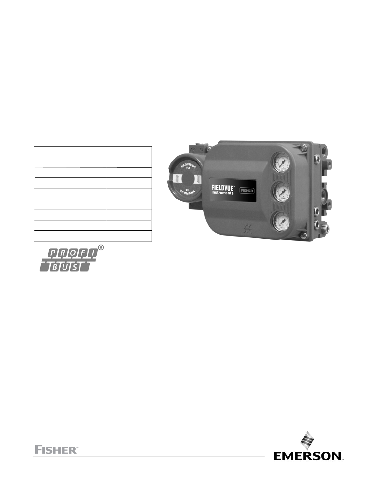
DVC6200p Digital Valve Controller
Fisher™ FIELDVUE™ DVC6200p Digital Valve
Controller
This manual applies to:
Device ID Number 0x1037
Device Revision 1
Hardware Revision 9
Firmware Revision 1.6.3.2.0
DD Revision 1.3/1.4
Instrument Level FD
Current GSD FC051037
Profile Specific GSD PA139710
DTM Revision 1.0
February 2021
www.Fisher.com


Instruction Manual
D103563X012
DVC6200p Digital Valve Controller
February 2021
Contents
Section 1 Introduction and Specifications 3.
Scope of Manual 3..............................
Conventions Used in the Manual 3................
Description 3..................................
Specifications 3................................
Related Information 7...........................
Educational Services 7...........................
Section 2 Wiring Practices 11.............
Quick Connect Cable Entry 11....................
Communication Connections 12..................
Section 3 Configuration 13...............
Transducer Block Mode 13......................
Guided Setup 14...............................
Manual Setup 14...............................
Reponse Control 15............................
Travel/Pressure Control 15..................
Travel Deviation Fallback 16.................
Travel Tuning Set 16.......................
Pressure Tuning Set 19.....................
Outblock Selection 19......................
Change Tuning and Integral Setting 20........
Performance Tuning 21.....................
Input Characterization 21...................
Output Synchronize 16.....................
Instrument 22................................
Enter Assembly Specification 23..............
Units 26.....................................
Security 26...................................
Classic View 26.................................
Alert Setup 27.................................
Travel Alerts 27...............................
Travel Limits 28...............................
Travel History Alerts 29.........................
Pressure Alerts 31.............................
Pressure A/B Alerts 31..........................
Temperature Alerts 32.........................
Electronics Alerts 32...........................
Memory Alerts 33.............................
Block Alerts 33................................
Proximity Alerts 33............................
Calibration Alerts 34...........................
AI Limits 34..................................
Section 5 Viewing Device
Variables and Diagnostics 41...........
Overview 41...................................
Status and Primary Purpose Variables 41..........
Device Information 41.........................
Service Tools 42................................
Active Alerts 42...............................
Diagnostics 42................................
Variables 42..................................
Maintenance 43...............................
Section 6 Maintenance and
Troubleshooting 45...................
Replacing the Magnetic Feedback Assembly 46......
Module Base Maintenance 46.....................
Tools Required 46.............................
Component Replacement 46....................
Removing the Module Base 47..................
Replacing the Module Base 48...................
Submodule Maintenance 49......................
I/P Converter 49...............................
Printed Wiring Board (PWB) Assembly 51..........
Pneumatic Relay 52............................
Gauges, Pipe Plugs or Tire Valves 52..............
Terminal Box 53................................
Removing the Terminal Box 53..................
Replacing the Terminal Box 53...................
Stroking the Digital Valve Controller Output 54......
Instrument Troubleshooting 54...................
Section 7 Parts 59......................
Parts Ordering 59...............................
Parts Kits 59...................................
Parts List 60...................................
Housing 60...................................
Common Parts 61.............................
Module Base 61...............................
I/P Converter Assembly 61......................
Relay 61.....................................
Terminal Box 62...............................
PWB Assembly 62.............................
Pressure Gauges, Pipe Plugs, or
Tire Valve Assemblies 62.....................
DVC6215 Feedback Unit 62......................
Section 4 Calibration 35.................
Calibration Overview 35.........................
Calibration 35..................................
Auto 35......................................
Manual 36...................................
Relay 36.....................................
Supply Pressure Sensor 39......................
Pressure A or B Sensor 38.......................
Auxiliary Terminal Calibration 40..................
Appendix A Principle of Operation 69......
Digital Valve Controller Operation 69..............
Appendix B Device Diagnostics 71.........
1

DVC6200p Digital Valve Controller
February 2021
Instruction Manual
D103563X012
Appendix C Blocks 73...................
Physical Block 73...............................
Transducer Block 84............................
Analog Output Function Block 103................
Discrete Output Function Block 109...............
Analog Input Function Block 114..................
Discrete Input Function Block 120.................
Alarm Transducer Block 124......................
Logbook Function Block 140......................
Appendix D Module Definitions, IO Bytes,
and Data Length 145..................
Glossary 155...........................
Index 159.............................
2

DVC6200p Digital Valve Controller
Instruction Manual
D103563X012
Introduction and Specifications
February 2021
Section 1 Introduction and Specifications
Installation, Pneumatic and Electrical Connections,
and Initial Configuration
Refer to the DVC6200 Series Quick Start Guide (D103556X012) for DVC6200p
installation, connection, and initial configuration information. If a copy of this quick
start guide is needed scan or click the field support code at the right, contact your
Emerson sales office
or visit our website at Fisher.com.
Scope of Manual
This instruction manual is a supplement to the DVC6200 Series Quick Start Guide (D103556X012) that ships with
every instrument. This instruction manual includes product specifications, reference materials, custom setup
information, calibration and maintenance procedures, and replacement part details for the DVC6200p digital valve
controller.
Scan or click
to access
field support
Note
All references to the DVC6200p digital valve controller include the DVC6205p base unit unless otherwise indicated.
Do not install, operate, or maintain a DVC6200p digital valve controller without being fully trained and qualified in
valve, actuator, and accessory installation, operation, and maintenance. To avoid personal injury or property damage,
it is important to carefully read, understand, and follow all of the contents of this manual, including all safety cautions
and warnings. If you have any questions about these instructions, contact your Emerson sales office before
proceeding.
Conventions Used in this Manual
Throughout this document, parameters are typically referred to by their common name or label.
Description
DVC6200p digital valve controllers are communicating, microprocessor‐based instruments. In addition to the
traditional function of converting a digital signal to a pneumatic output pressure, the DVC6200p digital valve
controller, using PROFIBUS PA communications protocol, gives easy access to information critical to process operation
as well as process control. It includes AO, AI, DO, and two DI function blocks in addition to the physical and transducer
blocks.
Using a compatible profibus configuration device, you can obtain information about the health of the instrument. You
can also obtain asset information about the actuator or valve manufacturer, model, and serial number. You can set
input and output configuration parameters and calibrate the instrument.
Using the PROFIBUS protocol, information from the instrument can be integrated into control systems.
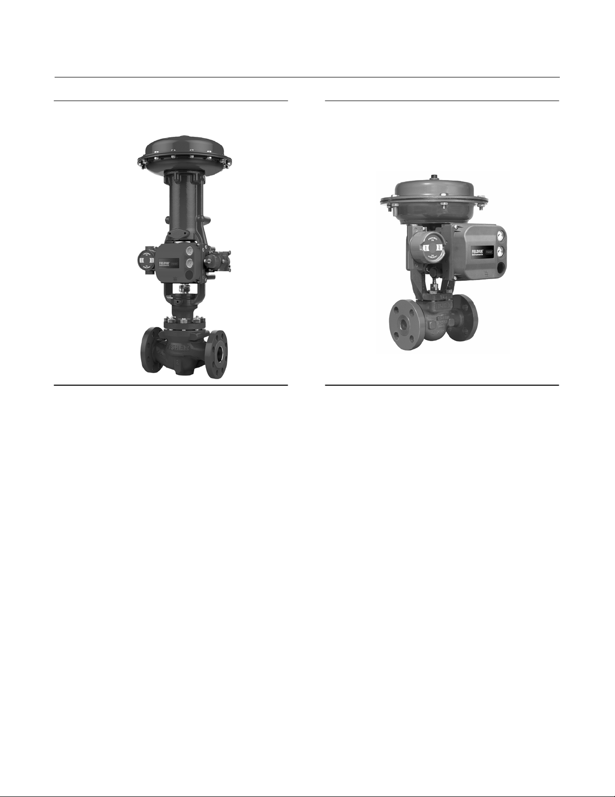
The DVC6200p can be mounted on single or double‐acting sliding‐stem actuators, as shown in figure 1‐1, or on rotary
actuators. It can also be integrally mounted to the Fisher GX control valve and actuator system, as shown in figure 1‐2.
The DVC6200p mounts on most Fisher and other manufacturers' rotary and sliding‐stem actuators.
3
DVC6200p Digital Valve Controller
Introduction and Specifications
February 2021
Instruction Manual
D103563X012
Figure 1‐1 FIELDVUE DVC6200p Digital Valve
Controller Mounted on a Fisher Sliding‐Stem Valve
Actuator
X1182-1_profibus
Figure 1‐2. FIELDVUE DVC6200p Digital Valve
Controller Integrally Mounted to a Fisher GX Control
Valve and Actuator System
W9616_profibus
Instrument Blocks
The digital valve controller is a block‐based device. For detailed information on the blocks within the digital valve
controller, see the Detailed Setup section of this manual.
The DVC6200p digital valve controller includes the physical and transducer block:
D Physical Block—The physical block contains the hardware specific characteristics associated with a device; it has no
input or output parameters. The physical block monitors and controls the general operation of other blocks within
the device. For example, when the mode of the physical block is Out of Service, it impacts all function blocks.
D Transducer Block—The transducer block connects the analog output function block to the I/P converter, relay, and
travel sensor hardware within the digital valve controller.
4

DVC6200p Digital Valve Controller
Instruction Manual
D103563X012
Introduction and Specifications
February 2021
Function Blocks
In addition to the physical and transducer block, the digital valve controller contains the following function blocks.
D Analog Output (AO) Function Block—The analog output function block accepts the output from another function
block (such as a PID block) and transfers it as an actuator control signal to the transducer block. If the DO block is
selected, the AO block is not functional.
D Discrete Output (DO) Function Block—The discrete output function block processes a discrete set point and sends it
to a specified output channel, which can be transferred to the transducer block for actuator control. In the digital
valve controller, the discrete output block provides both normally open or closed control and the ability to position
the valve in 5% increments for coarse throttling applications. If the AO block is selected, the DO block is not
functional.
D Analog Input (AI) Function Block—The analog input function block monitors the signal from a DVC6200p sensor or
internal measurement and provides it to another block.
D Discrete Input (DI) Function Block—The discrete input function block processes a single discrete input from a
DVC6200p and makes it available to other function blocks. In the digital valve controller, the discrete input function
block can provide limit switch functionality and valve position proximity detection.
D Alarm Transducer Block—The Alarm Transducer Block manages the device alarms. Active alarms are monitored and
displayed as active. Working with the Logbook Block those alarms active and configured are time/date stamped and
written to the Logbook block.
D Logbook Function Block—The Logbook Function Block will store any alarm that is active and configured to record an
occurrence of the alarm to the logbook. Logbook entries are written from active alarms in the Alarm Transducer
Block. Each Logbook entry is time/date stamped. A maximum of 260 log entries are allowed.
Specifications
Specifications for the DVC6200p digital valve controller are shown in table 1‐1.
5

DVC6200p Digital Valve Controller
Introduction and Specifications
February 2021
Table 1‐1. Specifications
Instruction Manual
D103563X012
Available Mounting
DVC6200p digital valve controller and DVC6215
feedback unit:
657/667 or GX actuators
Fisher rotary actuators,
applications
J Integral mounting to Fisher
J Integral mounting to
J Sliding‐stem linear
J Quarter‐turn rotary applications
DVC6205p base unit for 2 inch pipestand or wall
mounting (for remote-mount)
The DVC6200p digital valve controller or DVC6215
feedback unit can also be mounted on other
actuators that comply with IEC 60534-6-1, IEC
60534-6-2, VDI/VDE 3845 and NAMUR mounting
standards.
Function Block Suite
Standard (throttling) control includes AO, AI, DO, and
DI function blocks. Also included are a Logbook block
and an Alarm Transducer block.
Function Block Execution Times
AO Block: 6 ms
AI Block: 6 ms
DO Block: 6 ms
DI Block: 6 ms
Minimum Device Interval: 25 ms
Electrical Input
Voltage Level: 9 to 32 volts
Maximum Current: 19 mA
Reverse Polarity Protection: Unit is not polarity
sensitive
Termination: Bus must be properly terminated per
ISA SP50 guidelines
Digital Communication Protocol
PROFIBUS registered device
Certified to PROFIBUS Profile 3.02
Supply Pressure
(1)
Minimum Recommended: 0.3 bar (5 psig) higher
than maximum actuator requirements
Maximum: 10.0 bar (145 psig) or maximum pressure
rating of the actuator, whichever is lower
-continued-
Supply Medium
Air or Natural Gas
Supply medium must be clean, dry and
non-corrosive.
Per ISA Standard 7.0.01
A maximum 40 micrometer particle size in the air
system is acceptable. Further filtration down to 5
micrometer particle size is recommended. Lubricant
content is not to exceed 1 ppm weight (w/w) or
volume (v/v) basis. Condensation in the air supply
should be minimized.
Per ISO 8573-1
Maximum particle density size: Class 7
Oil content: Class 3
Pressure Dew Point: Class 3 or at least 10_C less than
the lowest ambient temperature expected
Output Signal
Pneumatic signal, up to full supply pressure
Minimum Span: 0.4 bar (6 psig)
Maximum Span: 9.5 bar (140 psig)
Action:
Steady-State Air Consumption
J Double, J Single Direct or J Reverse
(2)(3)
Standard Relay
At 1.4 bar (20 psig) supply pressure:
Less than 0.38 normal m
At 5.5 bar (80 psig) supply pressure:
Less than 1.3 normal m
3
/hr (14 scfh)
3
/hr (49 scfh)
Low Bleed Relay
At 1.4 bar (20 psig) supply pressure:
Average value 0.056 normal m
At 5.5 bar (80 psig) supply pressure:
Average value 0.184 normal m
Maximum Output Capacity
3
/hr (2.1 scfh)
3
/hr (6.9 scfh)
(2)(3)
At 1.4 bar (20 psig) supply pressure:
3
10.0 normal m
At 5.5 bar (80 psig) supply pressure:
29.5 normal m
Operating Ambient Temperature Limits
/hr (375 scfh)
3
/hr (1100 scfh)
(1)(4)
-40 to 85_C (-40 to 185_F)
-52 to 85_C (-62 to 185_F) for instruments utilizing
the Extreme Temperature option (fluorosilicone
elastomers)
-52 to 125_C (-62 to 257_F) for remote‐mount
feedback unit
6

Instruction Manual
D103563X012
Table 1‐1. Specifications (continued)
DVC6200p Digital Valve Controller
Introduction and Specifications
February 2021
Independent Linearity
(5)
Typical Value: ±0.50% of output span
Electromagnetic Compatibility
Meets EN 61326-1:2013
Immunity—Industrial locations per Table 2 of
the EN 61326-1 standard. Performance is
shown in table 1‐2 below.
Emissions—Class A
ISM equipment rating: Group 1, Class A
Lightning and Surge Protection—The degree of
immunity to lightning is specified as Surge immunity
in table 1‐2. For additional surge protection
commercially available transient protection devices
can be used.
Vibration Testing Method
Tested per ANSI/ISA‐75.13.01 Section 5.3.5. A
resonant frequency search is performed on all three
axes. The instrument is subjected to the ISA specified
1/2 hour endurance test at each major resonance.
Humidity Testing Method
Tested per IEC 61514-2
Electrical Classification
Hazardous Area Approvals
CSA— Intrinsically Safe, FISCO, Explosion‐proof,
Division 2, Dust Ignition‐proof
FM— Intrinsically Safe, FISCO, Explosion‐proof,
Non‐Incendive, Dust Ignition‐proof
ATEX— Intrinsically Safe, FISCO, Flameproof, Type n
Dust by intrinsic safety
IECEx— Intrinsically Safe, FISCO, Flameproof, Type n
Dust by intrinsic safety and enclosure
Electrical Housing
CSA— Type 4X, IP66
FM— Type 4X, IP66
ATEX— IP66
IECEx— IP66
CUTR— Customs Union Technical Regulations
(Russia, Kazakhstan, Belarus, and Armenia)
ESMA— Emirates Authority for Standardization and
Metrology - ECAS-Ex (UAE)
INMETRO— National Institute of Metrology, Quality
and Technology (Brazil)
KOSHA— Korean Occupational Safety & Health
Agency (South Korea)
KTL— Korea Testing Laboratory (South Korea)
NEPSI— National Supervision and Inspection Centre
for Explosion Protection and Safety of
Instrumentation (China)
PESO CCOE— Petroleum and Explosives Safety
Organisation - Chief Controller of Explosives (India)
SANS— South African Bureau of Standards
Contact your Emerson sales office
for
classification/certification specific information
Connections
Supply Pressure: 1/4 NPT internal and integral pad for
mounting 67CFR regulator
Output Pressure: 1/4 NPT internal
Tubing: 3/8‐inch recommended
Vent: 3/8 NPT internal
Electrical: 1/2 NPT internal or M20
Actuator Compatibility
Sliding‐Stem Linear
Linear actuators with rated travel between 6.35 mm
(0.25 inch) and 606 mm (23.375 inches)
Quarter‐Turn Rotary
Rotary actuators with rated travel between
45 degrees and 180 degrees
(6)
Weight
DVC6200p
Aluminum: 3.5 kg (7.7 lbs)
Stainless Steel: 8.6 kg (19 lbs)
DVC6205p: 4.1 kg (9 lbs)
DVC6215: 1.4 kg (3.1 lbs)
Other Classifications/Certifications
Natural Gas Certified, Single Seal Device— CSA, FM,
ATEX, and IECEx
Lloyds Register— Marine Type Approval
CCC— China Compulsory Certification
CML— Certification Management Limited (Japan)
Construction Materials
Housing, module base and terminal box:
A03600 low copper aluminum alloy (standard)
Stainless Steel (optional)
Cover: Thermoplastic polyester
Elastomers: Nitrile (standard)
Fluorosilicone (extreme temperature)
-continued-
7
DVC6200p Digital Valve Controller
Introduction and Specifications
February 2021
Table 1‐1. Specifications (continued)
Instruction Manual
D103563X012
Options
J Supply and output pressure gauges or
J Tire valves J Integral mounted filter regulator
J Low‐Bleed Relay
(7)
J Extreme Temperature
J Natural Gas Certified, Single Seal Device
J Remote Mount
Contact your Emerson sales office
(8)
J Stainless Steel
or go to Fisher.com
for additional information.
Declaration of SEP
Fisher Controls International LLC declares this
product to be in compliance with Article 4 paragraph
3 of the PED Directive 2014 / 68 / EU. It was designed
and manufactured in accordance with Sound
Engineering Practice (SEP) and cannot bear the CE
marking related to PED compliance.
However, the product may bear the CE marking to
indicate compliance with other applicable European
Community Directives.
NOTE: Specialized instrument terms are defined in ANSI/ISA Standard 51.1 - Process Instrument Terminology.
1. The pressure/temperature limits in this document and any other applicable code or standard should not be exceeded.
2. Normal m
3. Values at 1.4 bar (20 psig) based on a single-acting direct relay; values at 5.5 bar (80 psig) based on double-acting relay.
4. Temperature limits vary based on hazardous area approval. Lower temperature limit for CUTR Ex d approval with fluorosilicone elastomers is -53_C (-63.4_F).
5. Not applicable for travels less than 19 mm (0.75 inch) or for shaft rotation less than 60 degrees. Also not applicable for digital valve controllers in long-stroke applications.
6. Rotary actuators with 180 degree rated travel require a special mounting kit; contact your Emerson sales office for kit availability
7. The Quad O steady-state consumption requirement of 6 scfh can be met by a DVC6200p with low bleed relay A option, when used with up to 4.8 bar (70 psi) supply of
Natural Gas at 16_C (60_F). The 6 scfh requirement can be met by low bleed relay B and C when used with up to 5.2 bar (75 psi) supply of Natural Gas at 16_C (60_F).
8. 4‐conductor shielded cable, 18 to 22 AWG minimum wire size, in rigid or flexible metal conduit, is required for connection between base unit and feedback unit.
Pneumatic tubing between base unit output connection and actuator has been tested to 91 meters (300 feet). At 15 meters (50 feet) there was no performance
degradation. At 91 meters there was minimal pneumatic lag.
3
/hour - Normal cubic meters per hour at 0_C and 1.01325 bar, absolute. Scfh - Standard cubic feet per hour at 60_F and 14.7 psia.
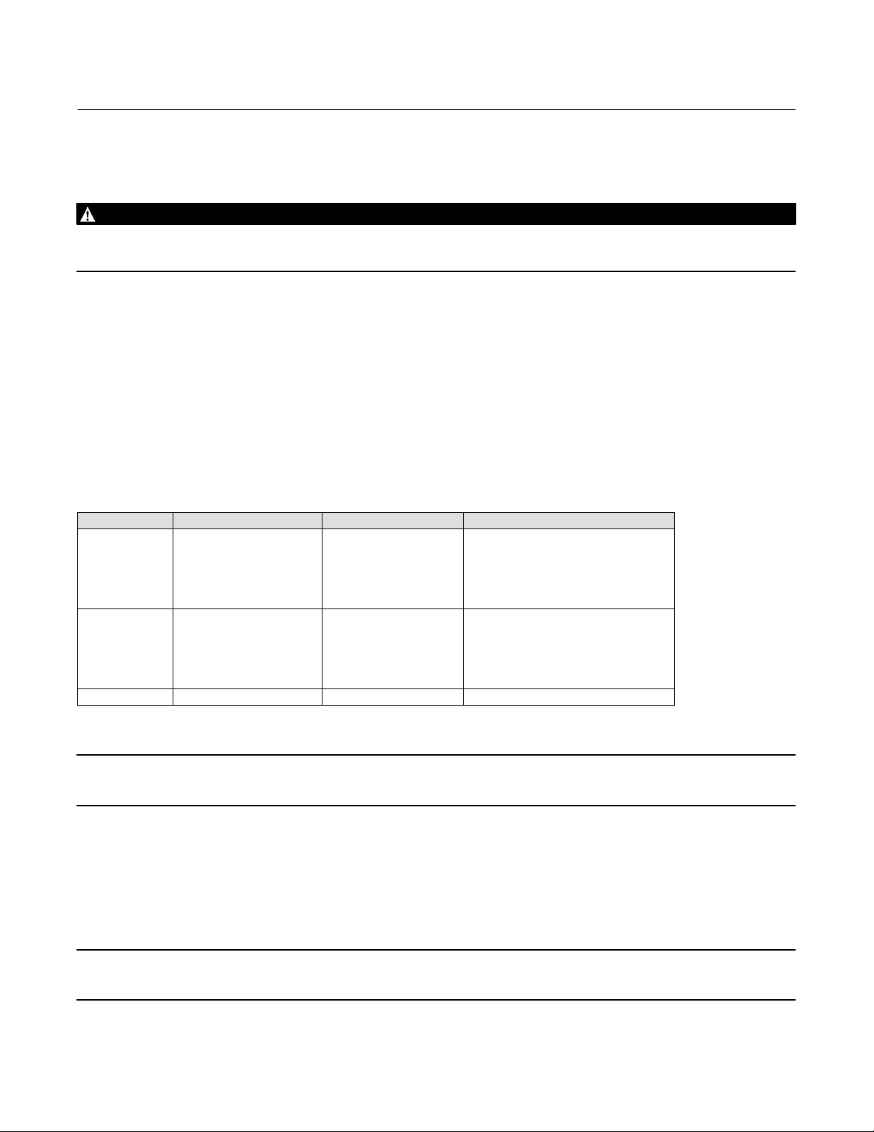
Table 1‐2. EMC Summary Results—Immunity
Port Phenomenon Basic Standard Test Level
Electrostatic discharge (ESD) IEC 61000‐4‐2
Enclosure
I/O signal/control
Performance criteria: +/- 1% effect.
1. A = No degradation during testing. B = Temporary degradation during testing, but is self‐recovering.
2. Excluding Simulate function, which meets Performance Criteria B.
Radiated EM field IEC 61000‐4‐3
Rated power frequency
magnetic field
Burst IEC 61000‐4‐4
Surge IEC 61000‐4‐5
Conducted RF IEC 61000‐4‐6
IEC 61000‐4‐8
4 kV contact
8 kV air
80 to 1000 MHz @ 10V/m with 1 kHz AM at 80%
1400 to 2000 MHz @ 3V/m with 1 kHz AM at 80%
2000 to 2700 MHz @ 1V/m with 1 kHz AM at 80%
30 A/m at 50/60 Hz
1 kV
1 kV
150 kHz to 80 MHz at 3 Vrms
Performance
Criteria
(2)
A
A
A
(2)
A
B
A
(1)
8

DVC6200p Digital Valve Controller
Instruction Manual
D103563X012
Introduction and Specifications
Related Information
PROFIBUS PA Installation and Wiring Guidelines
Refer to the DVC6200 Series Quick Start Guide (D103556X012) for installation and wiring information.
Related Documents
Other documents containing information related to the DVC6200p digital valve controller include:
February 2021
D DVC6200 Series Quick Start Guide (D103556X012
D CSA Hazardous Area Approvals - DVC6200 Series Digital Valve Controllers (D104203X012
D FM Hazardous Area Approvals - DVC6200 Series Digital Valve Controllers (D104204X012
D ATEX Hazardous Area Approvals - DVC6200 Series Digital Valve Controllers (D104205X012
D IECEx Hazardous Area Approvals - DVC6200 Series Digital Valve Controllers (D104206X012
D Device Setup and Accessing Communications and Calibration using Siemens SIMATIC Manager/PDM
(D103560X012
D Module Definitions, IO Bytes, and Data Length for DVC6200p PROFIBUS PA Digital Valve Controller (D104019X012
D Bulletin 62.1:DVC6200p FIELDVUE DVC6200p Digital Valve Controller (D103564X012
D Bulletin 62.1:DVC6200(S1) FIELDVUE DVC6200 Digital Valve Controller Dimensions (D103543X012
D Bulletin 62.1:Digital Valve Controller - Fisher FIELDVUE Digital Valve Controller Product Selection (D104363X012
All documents are available from your Emerson sales office or at Fisher.com.
)
)
)
)
)
)
)
)
)
Educational Services
)
For information on available courses contact:
Emerson Automation Solutions
Educational Services - Registration
Phone: +1-641-754-3771 or +1-800-338-8158
e‐mail: education@emerson.com
emerson.com/fishervalvetraining
9

DVC6200p Digital Valve Controller
Introduction and Specifications
February 2021
Instruction Manual
D103563X012
10
DVC6200p Digital Valve Controller
Instruction Manual
D103563X012
Installation
February 2021
Section 2 Wiring Practices2‐2‐
Quick Connect Cable Entry
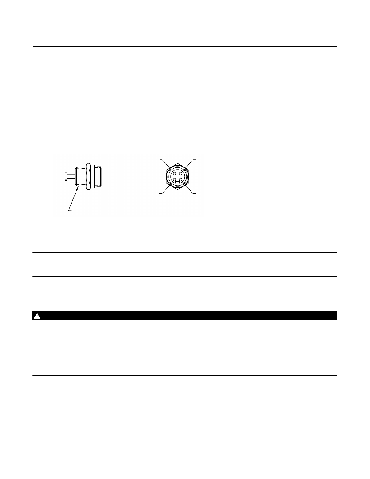
The DVC6200p is offered with a quick connect cable entry option, shown in figure 2‐1, for the PROFIBUS signal. The
quick connect cable entry provides an easier and more reliable interface to PROFIBUS devices and support modules by
providing a standard connection.
Figure 2‐1. Quick Connect Connector
1 (BROWN)
2 (GREEN/YELLOW)
1/2‐14 NPT
NOTE:
1. COLORS ARE WIRE COLORS.
GE61479-A
Note
The quick connect cable entry option is only available for intrinsically safe and non‐incendive installations.
3 (BLUE)
4 (GREY)
Refer to figure 7‐2 for identification of parts.
WARNING
Personal injury or property damage, caused by fire or explosion, can result from the discharge of static electricity. Connect
a 14 AWG (2.08 mm
gases are present. Refer to national and local codes and standards for grounding requirements.
To avoid static discharge from the plastic cover, do not rub or clean the cover with solvents. Clean with a mild detergent
and water only.
To avoid personal injury or property damage, do not use the Quick Connect option on instruments in explosion‐proof or
flameproof installations.
2
) ground strap between the digital valve controller and earth ground when flammable or hazardous
1. The quick connect cable entry should be installed on the digital valve controller at the factory. If it is, proceed to
step 3. If not continue with step 2.
2. To install the Quick Connect:
a. Remove the terminal box cap (key 4) from the terminal box (key 3).
b. Apply sealant to the threads of the quick connector.
11

DVC6200p Digital Valve Controller
Installation
February 2021
Instruction Manual
D103563X012
c. Insert the wire pigtail into the desired conduit opening on the terminal box. Tighten the quick connector in the
conduit opening.
d. The instrument is not polarity sensitive. Connect the blue wire to the negative LOOP terminal in the terminal
box. Connect the brown wire to the positive LOOP terminal. Isolate the green/yellow wire inside of the
DVC6200p, and ensure that the shield is totally isolated at the instrument end.
Note
The green/yellow wire is isolated inside the DVC6200p to help prevent ground loop issues.
e. Replace the terminal box cap on the terminal box and tighten until no gap remains. Secure the terminal box cap
by engaging the lock screw.
3. Connect the field wiring connector to the installed quick connector.
Communication Connections
A PROFIBUS PA secondary master interfaces with the DVC6200p digital valve controller from any wiring termination
point in the segment.
12
Instruction Manual
D103563X012
Section 3 Configuration3‐3‐
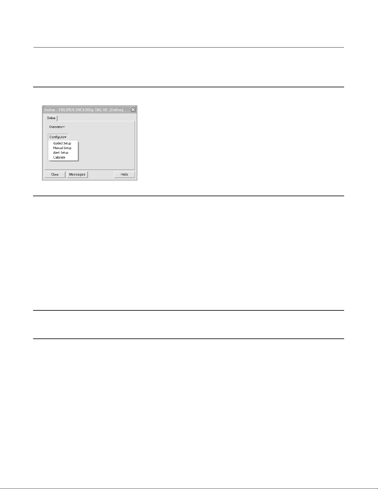
Figure 3‐1. Example of Typical Online Screen
DVC6200p Digital Valve Controller
Configuration
February 2021
Transducer Block Mode
Modes
The transducer block can be in one of two modes:
d Automatic (Auto)— This is the operational mode for this block. When the transducer block is in the Auto mode, all
other functions blocks will function normally.
d Out of Service (OOS)— Placing the transducer block in Out of Service mode changes the output to the zero power
(no I/P drive) condition.
Note
To setup and calibrate the instrument the transducer block mode must be in Auto and Write Locking (see page 26) must be Acyclic
Writeable.
13
DVC6200p Digital Valve Controller
Configuration
February 2021
Instruction Manual
D103563X012
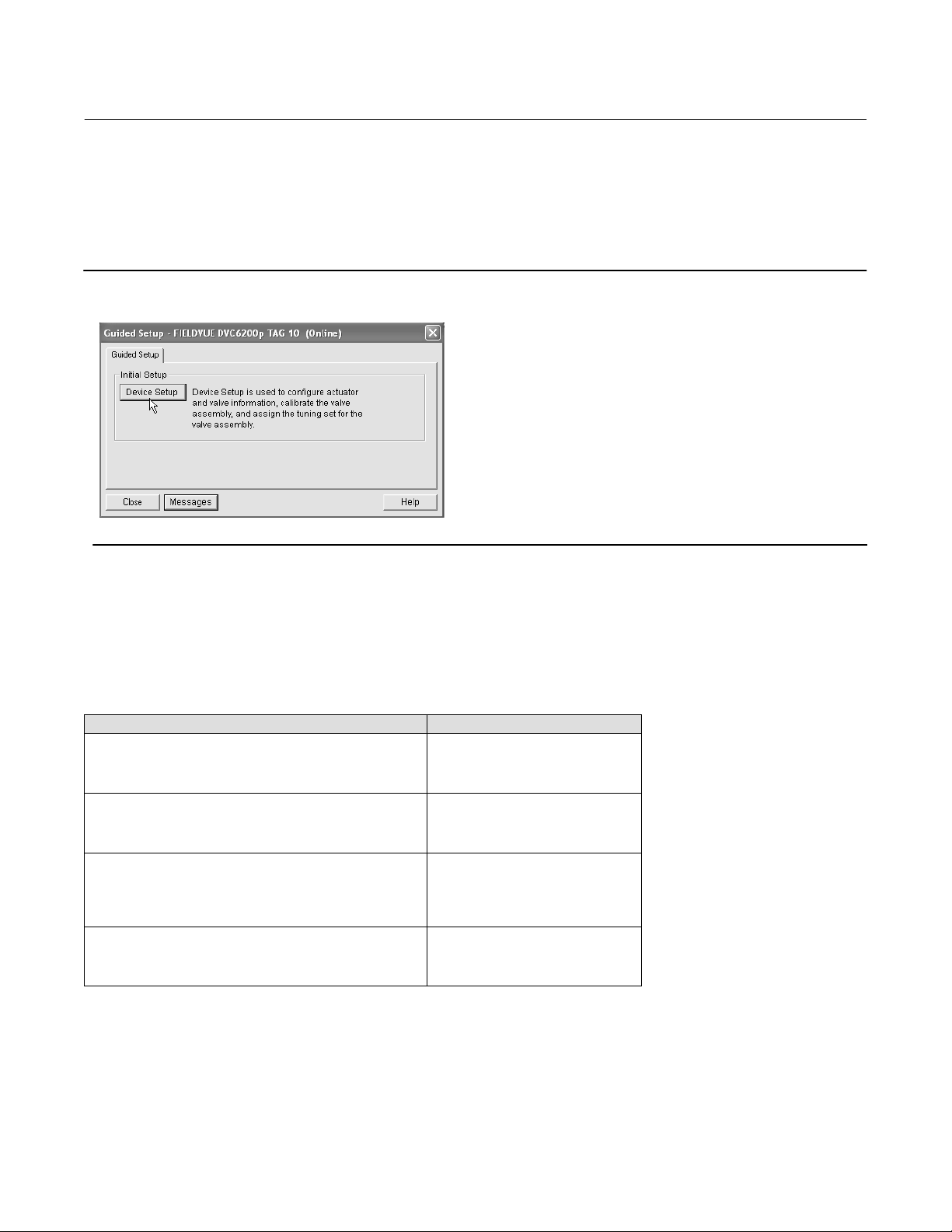
Guided Setup
D Device Setup— This procedure, accessible from the Guided Setup tab, as shown in figure 3‐2, is used to configure
actuator and valve information, calibrate the valve assembly, and assign the tuning set for the valve assembly.
Figure 3‐2. Example of Typical Guided Setup Tab
Manual Setup
Manual Setup allows you to configure the digital valve controller to your application. Table 3‐1 lists the default settings
for a standard factory configuration. You can adjust actuator response, set the various modes, alerts, ranges, travel
cutoffs and limits. You can also restart the instrument and set the protection.
Table 3‐1. Factory Default Settings
Setup Parameter Default Setting
Travel Cutoff Hi
Travel Cutoff Lo
Travel Integral Gain
Travel Calibration Trigger
Travel Integral Enable
Travel Integral Limit Hi
Travel Integral Limit Lo
Travel Integral Deadzone
Pressure Cutoff Hi
Pressure Cutoff Lo
Pressure Integral Deadzone
Pressure Integral Hi Limit
Pressure Integral Lo Limit
Input Characterization
Shutdown Trigger
Shutdown Recovery
Output Block Timeout
99.5%
0.5%
0 repeats/min
No
On
30%
-30%
0.25%
99.5%
-0.5%
0.25%
50.0%
-50.0%
Linear
All Off
All Auto Recovery
600 sec
14

DVC6200p Digital Valve Controller
Instruction Manual
D103563X012
Note
The DVC6200p may keep the Transducer Block Mode Out‐of‐Service if the instrument is not properly mounted.
To setup and calibrate the instrument, the Transducer Block Mode must be AUTO and the output block (AO or DO) must be OOS.
Protection must be None.
When performing procedures where you are prompted to change the mode, changes to Protection will be made automatically. If
you have a host system that overrides transducer block parameters ensure that the Protection setting is not
will result in transducer block parameters being overwritten. Refer to page 26 for additional information on setting Protection.
Configuration
February 2021
left as None. Doing so
Response Control
Travel/Pressure Control
D Travel/Pressure State indicates if the instrument is being used for travel control (position control) or as an I/P
(pressure control).
D Travel/Pressure Select
CAUTION
When using Pressure Fallback Manual Recovery or Pressure Fallback Auto Recovery, the valve travel has the potential of
moving rapidly, causing potential process instability when returning to Travel Control.
Note
Travel / Pressure Select must be set to Travel for double acting actuators.
Travel / Pressure Select determines if the instrument is setup for travel position or pressure control. Select Travel,
Pressure, Travel with Pressure Fallback/Auto recovery or Travel with Pressure Fallback/Manual Recovery. If the travel
sensor fails, and Travel with Pressure Fallback/Auto Recovery is selected, it will return to travel control when the travel
sensor starts working again. Travel with Pressure Fallback/Manual recovery will stay in pressure control until Travel
Pressure Select is changed to Travel or Travel with Pressure Fallback/Auto recovery. It is not necessary to enable the
Travel Sensor Alert for Pressure Fallback to occur.
D Travel Cutoff Hi defines the high cutoff point for the travel in percent (%) of pre‐characterized setpoint. Above this
cutoff, the travel target is set to 123.0% of the ranged travel. Travel Cutoff Hi is deactivated by setting it to 125.0%.
D Travel Cutoff Lo defines the low cutoff point for the travel in percent (%) of pre‐characterized setpoint. Below this
cutoff, the travel target is set to -23%. A Travel Cutoff Lo of 0.5% is recommended to help ensure maximum shutoff
seat loading. Travel Cutoff Lo is deactivated by setting it to -25.0%
D Pressure Tune Cutoff Hi defines the high cutoff point for the pressure in percent (%) of pre‐characterized setpoint.
Above this cutoff, the pressure target is set to 123.0%. A Pressure Cutoff Open of 99.5% is recommended to ensure
valve goes fully open. Pressure Tune Cutoff Hi is deactivated by setting it 125%.
15

DVC6200p Digital Valve Controller
Configuration
February 2021
D Pressure Tune Cutoff Lo defines the low cutoff point for the pressure in percent (%) of pre‐characterized setpoint.
Below this cutoff, the pressure target is set to -23%. A Pressure Tune Cutoff Lo of 0.5% is recommended to help
ensure maximum shutoff seat loading. Pressure Tune Cutoff Lo is deactivated by setting it to -25.0%.
D Pressure Range Hi is the high end of output pressure range. Enter the pressure that corresponds with 100% valve
travel when Zero Power Condition is closed, or 0% valve travel when Zero Power Condition is open. This pressure
must be greater than the Pressure Range Lo.
D Pressure Range Lo is the low end of the output pressure range. Enter the pressure that corresponds to 0% valve
travel when Zero Power Condition is closed, or 100% valve travel when Zero Power Condition is open. This pressure
must be less than the Pressure Range Hi.
Instruction Manual
D103563X012
Output Synchronize
Output Sync allows a bumpless transition from travel control mode to pressure control mode in the event of control
feedback switch.
D Bleed Rate is the time, in %/sec, for the transition to the user-specified setpoint. Select Enable or Disable.
Travel Deviation Fallback
D Travel Deviation Fallback occurs when a gross deviation exists between set point and actual travel. It switches to
Pressure Control and no longer uses the travel sensor to position the valve Select Enabled or Disabled.
D Fallback Point is the point, in percent (%) of travel, at which the instrument switches to Pressure Control.
D Fallback Time is the time, in seconds, that is required to reach the Travel Deviation Fallback Point.
D Deadband defines the Travel Deviation Fallback Deadband in percent (%).
D Minimum Supply is the minimum air supply, in psi or percent (%), required for the pressure control mode to activate
during Travel Deviation Fallback
Travel Tuning Set
WARNING
Changes to the tuning set may cause the valve/actuator assembly to stroke. To avoid personal injury or property damage
caused by moving parts, keep hands, tools, and other objects away from the valve/actuator assembly.
There are eleven Travel Tuning Sets to choose from. Each tuning set provides a preselected value for the digital valve
controller gain settings.
Tuning set C provides the slowest response and M provides the fastest response. Table 3‐2 lists the proportional gain,
velocity gain and minor loop feedback gain values for preselected tuning sets.
In addition, you can specify Expert tuning and individually set the proportional gain, velocity gain, and minor loop
feedback gain. Individually setting or changing any tuning parameter or running the Performance Tuner will
automatically change the tuning set to X (expert).
16

DVC6200p Digital Valve Controller
Instruction Manual
D103563X012
Table 3‐2. Gain Values for Preselected Travel Tuning Sets
Tuning Set Travel Proportional Gain Travel Velocity Gain Travel Minor Loop Feedback Gain
C
D
E
F
G
H
I
J
K
L
M
X (Expert) User Adjusted User Adjusted User Adjusted
Note
Use Expert tuning if standard tuning has not achieved the desired results.
4.4
4.8
5.5
6.2
7.2
8.4
9.7
11.3
13.1
15.5
18.0
3.0
3.0
3.0
3.1
3.6
4.2
4.8
5.6
6.0
6.0
6.0
35
35
35
35
34
31
27
23
18
12
12
Configuration
February 2021
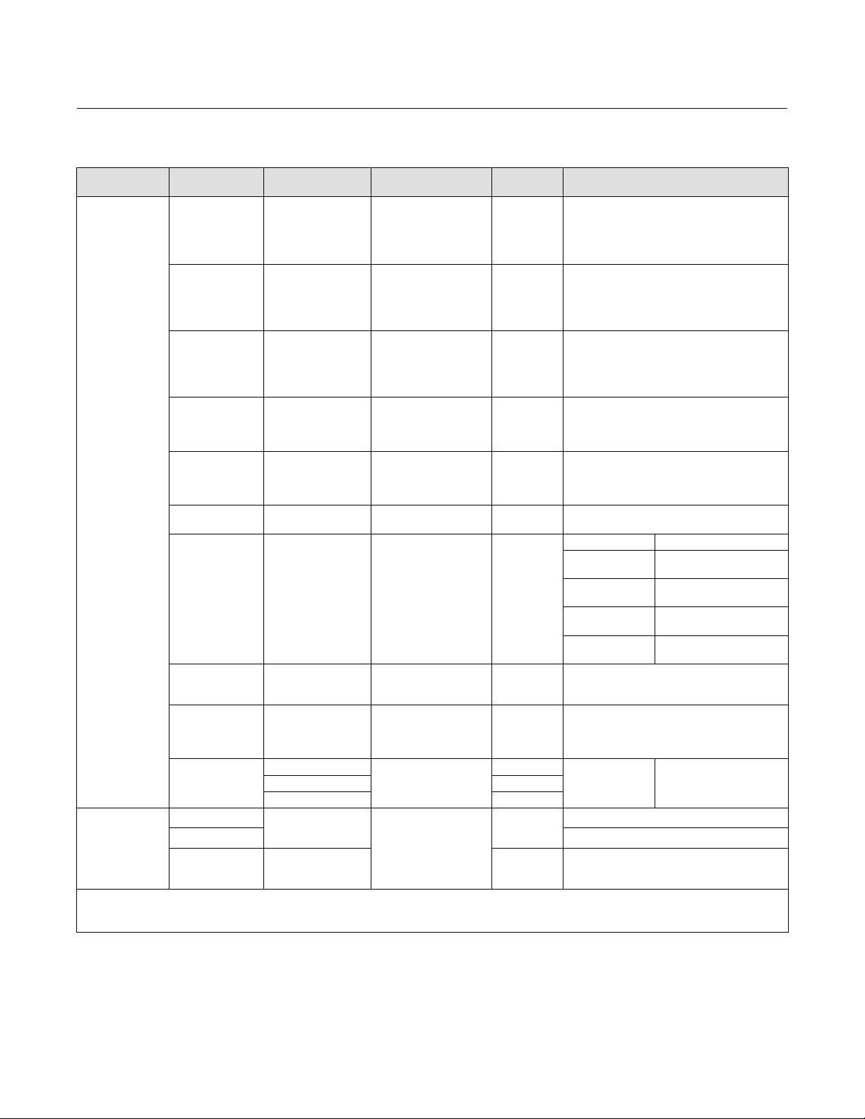
Table 3‐3 provides tuning set selection guidelines for Fisher and Baumann™ actuators. These tuning sets are
recommended starting points. After you finish setting up and calibrating the instrument, you may have to select either
a higher or lower tuning set to get the desired response.
For an actuator not listed in table 3‐3, you can estimate a starting tuning set by calculating the casing or cylinder
volume. Then, find an actuator in table 3‐3 with the closest equivalent volume and use the tuning set suggested for
that actuator.
17
DVC6200p Digital Valve Controller
Configuration
February 2021
Instruction Manual
D103563X012
Table 3‐3. Actuator Information for Initial Setup
Actuator
Manufacturer
Fisher
Baumann
NOTE: Refer to table 3‐5 for feedback connection (magnet assembly) information.
1. X = Expert Tuning. Proportional Gain = 4.2; Velocity Gain = 3.0; Minor Loop Feedback Gain = 18.0
2. Travel Sensor Motion in this instance refers to the motion of the magnet assembly.
3. Values shown are for Relay A and C. Reverse for Relay B.
Actuator Model Actuator Size Actuator Style
25
50
585C & 585CR
657
667
1051 & 1052
1061
1066 20, 27, 75 Piston Dbl w/o Spring Specify
1066SR
2052
3024
GX
Air to Extend
Air to Retract Towards the top of the instrument
Rotary
60
68, 80
100, 130
30, 30i
34, 34i, 40, 40i
45, 45i, 50, 50i
46, 46i, 60, 60i, 70,
70i & 80‐100
30, 30i
34, 34i, 40, 40i
45, 45i, 50, 50i
46, 46i, 60, 60i, 70,
70i, 76, 76i & 80‐100
20, 30
33
40
60, 70
30
40
60
68, 80, 100, 130
20
27, 75
1
2
3
GA 1.21
GA 1.31
GA 1.41
225
750 K
1200 M
16
32
54
10
25
54
Piston Dbl w/ or w/o
Spring. See actuator
instruction manual and
nameplate.
Spring & Diaphragm
Spring & Diaphragm
Spring & Diaphragm
(Window-mount)
Piston Dbl w/o Spring
Piston Sgl w/Spring
Spring & Diaphragm
(Window-mount)
Spring & Diaphragm
Spring & Diaphragm
Spring & Diaphragm
Starting
Tuning Set
E
F
J
L
M
H
K
L
M
H
K
L
M
H
I
K
M
J
K
L
M
G
L
H
K
M
E
H
K
(1)
X
C
E
H
E
H
J
Travel Sensor Motion
Relay A or C
User Specified
Away from the top of the instrument
Towards the top of the instrument
Away from the top of the instrument
Depends upon pneumatic connections. See
description for Travel Sensor Motion
Depends upon pneumatic connections. See
description for Travel Sensor Motion
Mounting Style Travel Sensor Motion
A
B
C
D
Away from the top of the instrument
For Po operating mode (air opens):
Towards the top of the instrument
For P
operating mode (air closes):
s
Away from the top of the instrument
Air to Open
Towards the top
of the instrument
Away from the top of the instrument
Away from the top of the
Towards the top of the
Towards the top of the
Away from the top of the
Away from the top of the
Specify
(2)
(3)
instrument
instrument
instrument
instrument
Air to Close
instrument
18
DVC6200p Digital Valve Controller
Instruction Manual
D103563X012
Configuration
February 2021
Pressure Tuning Set
WARNING
Changes to the tuning set may cause the valve/actuator assembly to stroke. To avoid personal injury or property damage
caused by moving parts, keep hands, tools, and other objects away from the valve/actuator assembly.
There are twelve Pressure Tuning Sets to choose from. Each tuning set provides a preselected value for the digital valve
controller gain settings.
Tuning set B provides the slowest response and M provides the fastest response. Tuning set B is appropriate for
controlling a pneumatic positioner. Table 3‐4 lists the proportional gain, pressure integrator gain and minor loop
feedback gain values for preselected tuning sets.
In addition, you can specify Expert tuning and individually set the pressure proportional gain, pressure integrator gain,
and pressure minor loop feedback gain. Individually setting or changing any tuning parameter will automatically
change the tuning set to X (expert).
Table 3‐4. Gain Values for Preselected Pressure Tuning Sets
Tuning Set Pressure Proportional Gain Pressure Integrator Gain Pressure Minor Loop Feedback Gain
B
C
D
E
F
G
H
I
J
K
L
M
X (Expert) User Adjusted User Adjusted User Adjusted
0.5
2.2
2.4
2.8
3.1
3.6
4.2
4.8
5.6
6.6
7.8
9.0
0.3
0.1
0.1
0.1
0.1
0.1
0.1
0.1
0.1
0.1
0.1
0.1
35
35
35
35
35
34
31
27
23
18
12
12
Note
Use Expert tuning only if standard tuning has not achieved the desired results.
Out Block Selection
Out Block Selection defines which output function block, Analog or Discrete, will control the setpoint of the valve.
Note
Select the AO function block if throttling control is required. Select the DO function block for on/off connectivity.
19

DVC6200p Digital Valve Controller
Configuration
February 2021
Instruction Manual
D103563X012
Change Tuning and Integral Settings
Travel Tuning
D Travel Tuning Set, there are eleven Travel Tuning Sets to choose from. Each tuning set provides a preselected value
for the digital valve controller gain settings.
D Travel Proportional Gain, for travel control tuning only. Changing this parameter will also change the tuning set to
Expert.
D Travel Velocity Gain, for travel control tuning only. Changing this parameter will also change the tuning set to
Expert.
D Travel MLFB Gain is the minor loop feedback gain for travel control only. Changing this parameter will also change
the tuning set to Expert.
D Travel Integral Gain (also called reset), is the ratio of the change in output to the change in input, based on the
control action in which the output is proportional to the time integral of the input.
D Travel Integral Dead Zone is a window around the Primary Setpoint in which the integral action is disabled. The dead
band is configurable from 0 to 2% corresponding to a symmetric window from 0% to +/-2% around the Primary
Setpoint. Integral Dead Zone is used to eliminate friction induced limit cycles around the Primary Setpoint when the
integrator is active. This dead zone value is used during the Auto Calibration of Travel procedure even if the travel
integral is disabled; in the case of Auto Calibration travel failures with piston actuators, this value should be set to
1%. Default value is 0.26%.
D Travel Integral Limit Hi provides an upper limit to the integrator output. The high limit is configurable from 0 to
100% of the I/P drive signal.
D Travel Integral Limit Lo provides a lower limit to the integrator output. The low limit is configurable from -100 to 0%
of the I/P drive signal.
D Travel Integral Enable is used to enable the integral setting to improve static performance by correcting for error
that exists between the travel target and actual travel.
Pressure Tuning
D Pressure Tuning Set, there are twelve Pressure Tuning Sets to choose from. Each tuning set provides a preselected
value for the digital valve controller gain settings.
D Pressure Proportional Gain, for pressure control tuning only. Changing this parameter will also change the tuning
set to Expert.
D Pressure Integral Gain (also called reset) is the ratio of the change in output to the change in input, based on the
control action in which the output is proportional to the time integral of the input. This feature is used during
pressure control for greater accuracy during pressure control/fallback. Changing this parameter will also change the
tuning set to Expert.
D Pressure Integral Dead Zone is a window around the Primary Setpoint in which the integral action is disabled. The
dead band is configurable from 0 to 2%.
D Pressure Integral Limit Hi provides an upper limit to the integrator output. The high limit is configurable from 0 to
100% of the I/P drive signal.
20

DVC6200p Digital Valve Controller
Instruction Manual
D103563X012
Configuration
February 2021
D Pressure Integral Limit Lo provides a lower limit to the integrator output. The low limit is configurable from -100 to
0% of the I/P drive signal.
D Pressure MLFB Gain is the minor loop feedback gain for the pressure control tuning set. Changing this parameter
will also change the tuning set to Expert.
Tuner
WARNING
During tuning the valve may move, causing process fluid or pressure to be released. To avoid personal injury and property
damage caused by the release of process fluid or pressure, isolate the valve from the process and equalize pressure on both
sides of the valve or bleed off the process fluid.
Tuner is used to determine digital valve controller tuning. It will move the valve slightly and monitor the effects of
small tuning changes until an optimum control response is achieved. Because the tuner can detect internal instabilities
before they become apparent in the travel response, it can generally optimize tuning more effectively than manual
tuning.
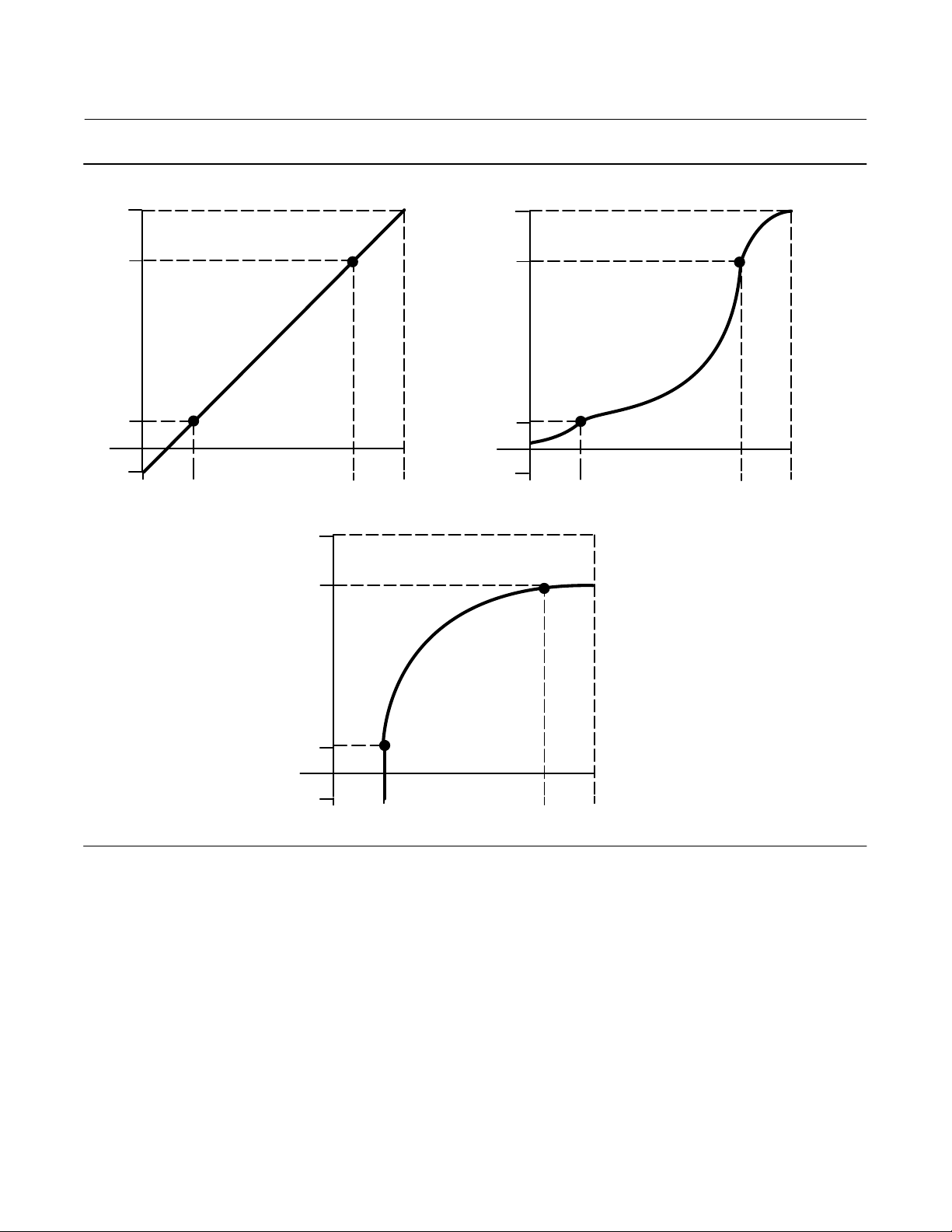
Input Characterization
Input Characterization defines the relationship between the travel target and the setpoint received from the output
block. Travel target is the output from the characterization function.
Linearization Table
You can select from the three fixed input characteristics shown in figure 3‐3 or you can select a custom characteristic.
Figure 3‐3 shows the relationship between the travel target and travel set point for the fixed input characteristics.
You can specify 21 points on a custom characteristic curve. Each point defines a travel target, in % of ranged travel, for
a corresponding set point, in % of ranged set point. Set point values range from -25.0% to 125%. Before modification,
the custom characteristic is linear. You cannot modify
Linearization Type
Select the linearization type:
No linearization (default is linear)
Linearization table
Equal percentage— a valve flow characteristic where equal increments of valve stem travel produce equal percentage
changes in existing flow, or
Quick opening— a valve flow characteristic where most of the change in flow rate takes place for small amounts of
stem travel from the closed position. The flow characteristic curve is basically linear through the first 40 percent of
stem travel.
the custom points if the Input Characterization is set to custom.
21
DVC6200p Digital Valve Controller
Configuration
February 2021
Instruction Manual
D103563X012
Figure 3‐3. Travel Target Versus Ranged Set Point, for Various Input Characteristics (Zero Power Condition = Closed)
125
100
Travel Target, %
0
-25
-25 0 125100
Set Point, %
Input Characteristic Linear
125
100
125
100
Travel Target, %
0
-25
-25 0 125100
Set Point, %
Input Characteristic Equal Percentage
Travel Target, %
0
-25
A6535‐1
-25 0 125100
Input Characteristic Quick Opening
Set Point, %
Instrument
Actuator Style— select spring & diaphragm, piston double‐acting without spring, piston single‐acting with spring, or
piston double‐acting with spring.
Valve Type— enter the type of valve, sliding‐stem or rotary, on which the instrument is mounted.
Feedback Connection— refer to table 3‐5 for Feedback Connection options. Choose the assembly that matches the
actuator travel range.
22
DVC6200p Digital Valve Controller
Instruction Manual
D103563X012
Note
As a general rule, do not use less than 60% of the magnet assembly travel range for full travel measurement. Performance will
decrease as the assembly is increasingly subranged.
The linear magnet assemblies have a valid travel range indicated by arrows molded into the piece. This means that the hall sensor
(on the back of the DVC6200p housing) has to remain within this range throughout the entire valve travel. The linear magnet
assemblies are symmetrical. Either end may be up.
Configuration
February 2021
Table 3‐5. Feedback Connection Options
Magnet Assembly
SStem #7 4.2-7 0.17-0.28 -
SStem #19 8-19 0.32-0.75 -
SStem #25 20-25 0.76-1.00 -
SStem #38 26-38 1.01-1.50 -
SStem #50 39-50 1.51-2.00 -
SStem #110 51-110 2.01-4.125 -
SStem #210 111-210 4.126-8.25 -
SStem #1 Roller > 210 > 8.25 60-90_
RShaft Window #1 - - 60-90_
RShaft Window #2 - - 60-90_
RShaft End Mount - - 60-90_
mm Inch Degrees
Travel Range
Maximum Supply Pressure— enter the maximum supply pressure in psi, bar, or kPa, depending on what was selected
for pressure units.
Relay Type— enter the Relay Type. There are three categories of relays that result in combinations from which to
select.
Relay Type: The relay type is printed on the label affixed to the relay body:
A = double‐acting or single acting
B = single‐acting, reverse
C= single‐acting, direct
Lo Bleed: The label affixed to the relay body indicates it is a low bleed version.
Zero Power Condition— identifies whether the valve is open or closed when instrument power is lost. If you are unsure
how to set this parameter, disconnect the segment loop power to the instrument. The resulting valve travel is the Zero
Power Condition.
Note
For bumpless restart of the valve on power-cycle ensure the IO_OPTS “Use Failsafe Value per Type on restart” parameter is
enabled. This parameter can be enabled in the Analog Output or Discrete Output block under the Manual Setup tab. Select Classic
View > AO or
DO Block > Mode and Manufacturer Specific > Use Failsafe Value per Type on Restart.
Enter Assembly Specification
Valve
D Valve Manufacturer— enter the identification number of the manufacturer of the valve on which the instrument is
mounted.
23

DVC6200p Digital Valve Controller
Configuration
February 2021
Instruction Manual
D103563X012
D Valve Model Number— enter the design letter or type number for the valve on which the instrument is mounted.
D Valve Serial Number—enter the serial number of the valve on which the instrument is mounted.
D Valve Type— enter the type of valve, sliding‐stem or rotary, on which the instrument is mounted.
D Valve Size— enter the size of the valve on which the instrument is mounted.
D Valve Class— enter the valve pressure class rating.
D Rated Travel— the nominal stroke of the valve in units that are the same as that of OUT_SCALE. Read only.
D Actual Travel— enter the actual travel in inches or mm for sliding-stem valves, or in degrees of rotation for rotary
valves.
D Shaft Stem Diameter— enter the valve stem diameter in inches or millimeters.
D Packing Type— enter the valve packing construction .
D Inlet Pressure— enter the valve inlet pressure in psig, kPa, Bar, inHg, inH
D Outlet Pressure— enter the valve outlet pressure in psig, kPa, Bar, inHg, inH
O, or kg/cm2.
2
O, or kg/cm2.
2
Trim
D Seat Type— enter the valve seat type.
D Leak Class— enter the valve leak class.
D Port Diameter— enter the valve port diameter in inches or mm.
D Port Type— enter the valve port type.
D Flow Direction— enter the flow direction through the valve.
D Push Down To— enter the effect on valve movement when the stem is moved down.
D Flow Tends To— enter the effect on valve travel with increasing flow.
D Unbalanced Area— enter the valve unbalanced area in in
2
, cm2 or mm2.
Actuator
D Actuator Manufacturer— enter the manufacturer's identification number of the actuator on which the instrument is
mounted.
D Actuator Model Number— enter the type number for the actuator on which the instrument is mounted.
D Actuator Serial Number— enter the serial number for the actuator on which the instrument is mounted.
D Actuator Size— enter the size of the actuator on which the instrument is mounted.
D Actuator Fail Action— sets actuator action to be performed upon loss of actuator air pressure .
24

DVC6200p Digital Valve Controller
Instruction Manual
D103563X012
Configuration
February 2021
D Feedback Connection —refer to table 3‐5 for Feedback Connection options. Choose the assembly that matches the
actuator travel range.
D Travel Sensor Motion— establishes the proper valve travel sensor (feedback) rotation/movement. For quarter‐turn
actuators determine rotation by viewing the rotation of the magnet assembly from the back of the instrument.
WARNING
If you answer YES to the prompt for permission to move the valve when setting the Travel Sensor Motion, the instrument
will move the valve through its full travel range. To avoid personal injury and property damage caused by the release of
pressure or process fluid, isolate the valve from the process and equalize pressure on both sides of the valve or bleed off the
process fluid.
Note
Travel Sensor Motion in this instance refers to the motion of the magnet assembly. Note that the magnet assembly may be
referred to as a magnetic array in user interface tools.
For instruments with relay A or C If increasing air pressure at output A causes the magnet assembly to move up, or the
actuator shaft to rotate counterclockwise, enter “Counterclockwise/Towards Top of Instrument.” If it causes the
magnet assembly to move down, or the actuator shaft to rotate clockwise, enter “Clockwise/Away From Top of
Instrument.”
For instruments with relay B If decreasing air pressure at output B causes the magnet assembly to move up, or the
actuator shaft to rotate counterclockwise, enter “Counterclockwise/Towards Top of Instrument.” If it causes the
magnet assembly to move down, or the actuator shaft to rotate clockwise, enter “Clockwise/Away From Top of
Instrument.”
D Lever Style— enter the lever style for rotary actuators as either Pivot Point or Rack and Pinion.
D Lever Arm Length—defines the lever arm length for rotary actuators.
D Effective Area — enter the actuator effective area in in
2
, cm2, or mm2.
D Air— select Opens or Closes, indicating the effect of increasing air pressure on the valve travel.
D Upper Bench Set— enter the upper actuator operating pressure.
D Lower Bench Set— enter the lower actuator operating pressure.
D Nominal Supply Pressure— enter the nominal instrument supply pressure.
D Spring Rate— enter the actuator spring rate in lbsSin or NSm.
Reference
D Trim Style 1— enter the valve trim style.
D Trim Style 2— enter the valve trim style.
D Stroking Time Open— enter the time required to stroke the valve from closed to open.
D Stroking Time Close— enter the time required to stroke the valve from open to closed.
Note
Stroking Time Open and Stroking Time Close are used as a point of reference only; they do not reflect the actual time required to
stroke the valve from closed to open or open to closed.
25

DVC6200p Digital Valve Controller
Configuration
February 2021
D Field Serial Number— enter the instrument serial number.
Units
Select the appropriate units for your application.
D Temperature Unit— _C or _F
Instruction Manual
D103563X012
D Pressure Unit— psig, kPa, Bar, inHg, inH
D Travel Unit— cm, mm, inch, or deg
D Length Unit— cm, mm, or inch
D Area Unit— in
D Spring Rate Unit— lbsSin or NSm
2
, cm2, or mm
2
O, or kg/cm
2
2
Security
Write Locking— select the appropriate level of software write protection.
D Acyclic Writeable— all parameters are writeable (not locked).
D Acyclic Write Refused— acyclic writes to all parameters are denied, except WRITE_LOCKING, TAB_ENTRY and
ACTUAL_POST_READ_NUMBER parameter.
Protection
To configure a parameter in the digital valve controller Protection must be set at or above that parameters protection
level. In addition, protection is provided for various transducer block parameters, as indicated in the Protect Category
column of table C‐3, to prevent inadvertently overwriting key data by the host system or user.
D None— will not protect any transducer block parameters.
D Calibration— will protect only Calibration transducer block parameters.
D Setup and Calibration— will protect only Setup and Calibration transducer block parameters.
D All— will protect all transducer block parameters.
Note
Device Setup Auto Travel and Manual Travel automatically change transducer block protection for the user.
See table C‐3 for individual parameter details.
Classic View
Classic view allows you to view all of the variables in the Physical, Transducer, and function blocks.
26

DVC6200p Digital Valve Controller
Instruction Manual
D103563X012
Configuration
February 2021
Alert Setup
Instrument Alert Conditions, when enabled, detect many operational and performance issues that may be of interest.
To view these alerts, you must open the appropriate status screen on a host system.
Configure Alert Category— select Failed, Maintenance, or Advisory.
Failed A failed alert indicates a failure within the device that will make the device or some part of the device
non‐operational.
Maintenance A maintenance alert indicates the device or some part of the device needs maintenance soon.
Advisory An advisory alert indicates informative conditions that do not have a direct impact on the device's
primary functions.
Supervision— if Supervision is selected, the Binary Message (BM) is immediately active. If Supervision is not selected,
you can choose between active and inactive BM.
Logbook— indicate if the alert should be stored in the Logbook function block. The logbook function block contains
binary messages and status information about the stored alerts. Each logbook entry is time/date stamped. A
maximum of 260 log entries are allowed.
Alarm Transducer
Active Messages
Active Messages provides an overview of the active alerts. Select the appropriate tab within Configure > Alert Setup to
view and set alarm limits. Alert details are covered by tab below.
Mode
The Alarm transducer block supports two modes of operation.
D Automatic (Auto)
D Out of Service (OOS)
Travel Alerts
Note
The alerts contained in this section are valid for both travel and pressure control.
Travel Target
Travel target is the output from the characterization function.
Travel
Travel displays the actual position of the valve in percent (%) of calibrated travel.
27

DVC6200p Digital Valve Controller
Configuration
February 2021
Instruction Manual
D103563X012
Travel Deviation
D Travel Deviation—Travel Deviation displays the absolute difference in percent between Travel Target and Actual
Travel.
D Deviation Alert Point— the alert point for the difference, expressed in percent (%), between the travel target and the
actual travel. When the difference exceeds the alert point for more than the Travel Deviation Time, the Travel
Deviation Alert is set.
D Deviation Time— the time, in seconds, that the travel deviation must exceed the Travel Deviation Alert Point before
the alert is set.
Travel Open
This alert is active if the Travel goes above the Travel Open Alert Point.
D Open Alert Point— the value of the travel in percent (%) or ranged travel, which, when exceeded, sets the Travel
Open Alert.
D Open Deadband— the travel, in percent (%) of ranged travel, required to clear a Travel Open alert once it has been
set.
Travel Closed
This alert is active if the Travel goes below than the Travel Closed Alert Point.
D Closed Alert Point— set when the value of the travel, in percent (%) of ranged travel, goes below the Travel Closed
Alert Point.
D Closed Deadband— the travel, in percent (%) of ranged travel, required to clear a Travel Closed alert once it has been
set.
Travel Limits
Travel Limit Hi Hi
This alert is active if the Travel exceeds the Travel Hi Hi Alert point. See figure 3‐4.
D Hi Hi Alert Point— the value of the travel, in percent (%) of ranged travel, which, when exceeded, sets the Travel Alert
Hi Hi alert.
D Hi Hi Deadband— the travel, in percent (%) of ranged travel, required to clear a Travel Hi Hi alert, once it has been
set.
Figure 3‐4. Travel Hi Alert Deadband
ALERT IS SET
TRAVEL ALERT
HIGH POINT
28
TRAVEL ALERT
DEADBAND
ALERT IS CLEARED
A6532

DVC6200p Digital Valve Controller
Instruction Manual
D103563X012
Configuration
February 2021
Travel Limit Lo Lo
This alert is active if the Travel is lower than the Travel Lo Lo Alert point. See figure 3‐5.
D Lo Lo Alert Point— set when the value of the travel, in percent (%) of ranged travel, goes below the Travel Lo Lo Alert
Point .
D Lo Lo Deadband— the travel, in percent (%) of ranged travel, required to clear a Travel Lo Lo alert once it has been
set.
Figure 3‐5. Travel Lo Alert Deadband
ALERT IS CLEARED
TRAVEL ALERT
DEADBAND
TRAVEL ALERT
ALERT IS SET
LO POINT
A6532‐1
Travel Limit Hi
This alert is active if the Travel exceeds the Travel Hi Alert point. See figure 3‐4.
D Hi Alert Point— the Travel Hi Alert set if the ranged travel rises above the Travel Hi Alert Point. Once the alert is set,
the ranged travel must fall below the alert high point set by the Travel Hi Deadband before the alert is cleared.
D Hi Deadband— the travel, in percent (%) of ranged travel, required to clear a Travel Hi Alert, once it has been set.
Travel Limit Lo
This alert is active if the Travel is lower than the Travel Lo Alert point. See figure 3‐5.
D Lo Alert Point— the Travel Lo Alert is set when the value of the travel, in percent (%) of ranged travel, goes below the
Travel Lo Alert Point.
D Travel Lo Deadband— the travel, in percent (%) of ranged travel, required to clear a travel lo alert, once it has been
set.
Travel History Alerts
Cycle Counter
This alert is active if the Cycle Counter exceeds the Cycle Counter Alert Point. It is cleared after you reset the Cycle
Counter to a value less than the alert point.
D Cycle Counter— records the number of times the travel changes direction. The change in direction must occur after
the deadband has been exceeded before it can be counted as a cycle. See figure 3‐6. You can reset the Cycle
Counter by configuring it as zero.
29

DVC6200p Digital Valve Controller
Configuration
February 2021
Figure 3‐6. Cycle Counter Deadband (set at 10%)
Deadband exceeded, and direction
changed, new Reference Point
established
Point at which
Deadband Reference
Point
A6533‐1
Deadband (+/- 5%)
cycle is counted
Instruction Manual
D103563X012
D Cycle Counter Limit— is the value of the Cycle Counter, in cycles, which, when exceeded, sets the Cycle Counter
Alert.
D Cycle Counter Deadband— the area around the travel reference point, in percent (%) of ranged travel, that was
established at the last increment of the Cycle Counter. This area must be exceeded before a change in travel
direction can be counted as a cycle. See figure 3‐6.
Travel Accumulator
This alert is active if the Travel Accumulator exceeds the Travel Accumulator Alert Point. The Travel Accumulator Alert
is set when the Travel Accumulator value exceeds the Travel Accumulator Alert Point. It is cleared after you reset the
Travel Accumulation to a value less than the alert point.
D Travel Accumulator— records the total change in travel, in percent (%) of ranged travel, since the accumulator was
last cleared. The value of the Travel Accumulator increments when the magnitude of the change exceeds the Travel
Accumulator Dead‐band. See figure 3‐7. You can reset the Travel Accumulator by configuring it to zero.
D Travel Accumulator Limit— the value of the Travel Accumulator, in percent (%) of ranged travel, which, when
exceeded, sets the Travel Accumulator Alert.
D Travel Accumulator Deadband— the area around the travel reference point, in percent (%) of ranged travel, that was
established at the last increment of the accumulator. This area must be exceeded before a change in travel can be
accumulated. See figure 3‐7.
Travel Sensor
This alert is active if the Travel Sensor reading is outside the functional range, or the sensor becomes disconnected.
30

Instruction Manual
D103563X012
Figure 3‐7. Travel Accumulator Deadband (set at 10%)
Deadband exceeded,
new Reference Point
established
DVC6200p Digital Valve Controller
Configuration
February 2021
Deadband Reference
Point
A6534
Deadband (+/- 5%)
This amount of change is
added to the Travel
Accumulator
Pressure Alerts
Supply Pressure Hi Alert
This alert is active when the supply pressure exceeds the Supply Pressure Hi Alert Point.
D Supply Pressure Hi Alert Point— when the supply pressure exceeds the supply pressure alert point, the supply
pressure alert is active.
Supply Pressure Lo Alert
This alert is active when the supply pressure is lower than the Supply Pressure Lo Alert Point.
D Supply Pressure Lo Alert Point— when the supply pressure falls below the supply pressure alert point, the supply
pressure alert is active. To disable the supply pressure alert, set Supply Pressure Alert Point to zero.
Supply Pressure Sensor
This alert is active if the Supply Pressure Sensor reading is outside the functional range.
Pressure Fallback
This alert is active if a travel sensor failure or a gross travel deviation has resulted in fallback to pressure control.
Pressure A/B Alerts
This alert is active if the configured Pressure Sensor reading (Port A or Port B) is outside the functional range.
31

DVC6200p Digital Valve Controller
Configuration
February 2021
Instruction Manual
D103563X012
Temperature Alerts
Temperature Hi
This alert is active if the temperature is greater than the Temperature Hi Alert Point.
D Temperature Hi Alert Point— active when the instrument temperature exceeds the Temperature Hi Alert Point.
Temperature Low
This alert is active if the temperature is lower than the Temperature Lo Alert Point.
D Temperature Lo Alert Point— active when the instrument temperature is lower than the Temperature Lo Alert Point.
Temperature Sensor
This alert is active if the Temperature Sensor reading is outside the functional range.
D Temperature—Degrees Fahrenheit or Celsius. The temperature is measured from a sensor mounted on the digital
valve controller's printed wiring board.
Electronics Alerts
Drive Current Alert
This alert is active when the difference between the expected Drive Current and the actual Drive Current has exceeded
the Drive Current Alert Time.
D Drive Current Alert Point— when the absolute difference between the Drive Current and Drive Signal exceeds the set
threshold for greater than the Drive Current Alert Time.
D Drive Current Alert Time— the maximum time, in seconds, that the Drive Current Alert Point can be exceeded
before the Drive Current Alert is active.
Drive Signal
The Drive Signal displays the commanded Drive Signal being sent to the I/P converter as a percentage of the maximum
drive.
This alert is active if one of the following conditions exist:
Where Zero Power Condition is defined as closed:
Drive Signal < 10% and Calibrated Travel > 3%
Drive Signal > 90% and Calibrated Travel < 97%
Where Zero Power Condition is defined as open:
Drive Signal < 10% and Calibrated Travel < 97%
Drive Signal > 90% and Calibrated Travel > 3%
32

DVC6200p Digital Valve Controller
Instruction Manual
D103563X012
Configuration
February 2021
Memory Alerts
Program Memory Alert
This alert is active if a pending Flash or NVM failure is present.
Static Memory Alert
This alert is active if a failure occurs in the FRAM memory where the static parameters are stored.
Processor Alert
This alert is active if a failure occurs in the I/O processor.
Block Alerts
Output Block Timeout
This alert is active if the analog or discrete output block has not executed for longer than the configured timeout.
D Output Execution Interval—the maximum time between updates from the AO or DO block to the transducer block
setpoint.
Blocks Set to Default
This alert is active if the physical block has undergone Restart with Defaults. This will stay active until the transducer
block is changed from Out of Service.
Proximity Alerts
Proximity Hi Hi Alert
This alert is active if the Travel is within the detection band set by the Travel Hi Hi Alert Point and the Travel Hi Hi
Deadband.
Proximity Hi Alert
This alert is active if the Travel is within the detection band set by the Travel Hi Alert Point and the Travel Hi Deadband.
Proximity Lo Lo Alert
This alert is active if the Travel is within the detection band set by the Travel Lo Lo Alert Point and the Travel Lo Lo
Deadband.
Proximity Lo Alert
This alert is active if the Travel is within the detection band set by the Travel Lo Alert Point and the Travel Lo Deadband.
33

DVC6200p Digital Valve Controller
Configuration
February 2021
Instruction Manual
D103563X012
Calibration Alerts
Auxiliary Terminal Shorted Alert
This alert is active when the Auxiliary Terminal is shorted, to perform auto calibration or auto tuning, for more than the
set time.
Calibration Automatic
This alert is active when Auto calibration is in progress.
Calibration by Hand
This is alert is active when Manual calibration is in progress.
AI Limits
The following alerts are active if the set limit is exceeded.
AI Hi Hi Limit Exceeded
AI Hi Limit Exceeded
AI Lo Lo Limit Exceeded
AI Lo Limit Exceeded
34

DVC6200p Digital Valve Controller
Instruction Manual
D103563X012
Calibration
February 2021
Section 4 Calibration 4-4-
Calibration Overview
When a DVC6200p digital valve controller is ordered as part of a control valve assembly, the factory mounts the digital
valve controller on the actuator and connects the necessary tubing, then sets up and calibrates the controller.
For digital valve controllers that are ordered separately perform Device Setup to configure and calibrate the
instrument. Calibration of the pressure sensors generally is unnecessary; however if pressure sensor calibration is
required follow the appropriate procedure below.
For detailed calibration information, refer to the following calibration procedures.
Calibration
WARNING
During calibration the valve will move full stroke. To avoid personal injury and property damage caused by the release of
pressure or process fluid, isolate the valve from the process and equalize pressure on both sides of the valve or bleed off the
process fluid.
D Auto Calibration —This procedure automatically calibrates the travel. The calibration procedure uses the valve and
actuator stops as the 0% and 100% calibration points.
D Manual Calibration —This procedure permits manual calibration of the travel. This calibration procedure allows you
to determine the 0% and 100% calibration points.
D Relay —This procedure permits adjustment of the pneumatic relay.
If a double‐acting relay is used, you will be prompted to run the relay adjustment when auto or manual calibration is
selected. Select Yes to adjust the relay, select No to proceed with calibration. For additional information, refer to Relay
Adjustment in this section.
Note
Relay Adjustment is only available for the double‐acting relay (Relay A).
D Pressure A— This procedure permits calibrating the pressure A sensor. Normally the sensor is calibrated at the
factory and should not need calibration.
D Pressure B —This procedure permits calibrating the pressure B sensor. Normally the sensor is calibrated at the
factory and should not need calibration.
D Supply Pressure —This procedure permits calibrating the supply pressure sensor. Normally the sensor is calibrated at
the factory and should not need calibration.
Auto Calibration
Select Auto Calibration on the Travel tab from the Configure > Calibrate menu.
35

DVC6200p Digital Valve Controller
Calibration
February 2021
Follow the prompts to automatically calibrate travel.
1. The auto calibration procedure is automatic. It is completed when the calibration menu shows the progress is 100%
complete.
During calibration, the instrument seeks the high and low end points. By searching for the end points, the
instrument establishes the limits of physical travel, i.e. the actual travel 0 and 100% positions. This also determines
how far the relay beam swings to calibrate the sensitivity of the beam position sensor.
2. Select the Calibration Type; Auto calibrate-Standard or Auto calibrate-Extended. Auto calibrate-Standard is used for
most applications. Actuators with boosters or special accessories may require Auto calibrate-Extended.
3. Enter the name of the person performing the calibration procedure.
4. Enter the location of the calibration procedure.
5. Enter the date of the calibration procedure.
6. Place the instrument in Auto mode for the valve to track input.
Instruction Manual
D103563X012
Manual Calibration
Select Manual Calibration on the Travel tab from the Configure > Calibrate menu.
Follow the prompts to manually calibrate travel.
Note
0% Travel = Valve Closed ; 100% Travel = Valve Open
1. From the adjustment menu, select the direction and size of change required to set the travel at 100% (move the
valve to any point between 10% and 90% open). Select the changes of 10%, 5%, 1%, -1%, -5% and -10%, respectively,
to choose the travel feedback movement. Select Next to implement the adjustment.
If another adjustment is required, repeat step 1. Otherwise, select Done and go to step 2.
2. From the adjustment menu, select the direction and size of change required to set the travel to 0% (move the valve
to close).
If another adjustment is required, repeat step 2. Otherwise, select Done and go to step 3.
3. Enter the name of the person performing the calibration procedure.
4. Enter the location of the calibration procedure.
5. Enter the date of the calibration procedure.
6. Place the Transducer Block Mode in Auto and verify that the travel properly tracks the input.
Relay
Select Relay on the A/B Pressure Sensor tab from the Configure > Calibrate menu. Follow the prompts to check relay
adjustment. Replace the digital valve controller cover when finished.
Note
Single-acting Relay B and C are not user‐adjustable.
36

DVC6200p Digital Valve Controller
Instruction Manual
D103563X012
Calibration
February 2021
Double‐Acting Relay
The double‐acting relay is designated by “Relay A” on a label affixed to the relay itself. For double‐acting actuators, the
valve must be near mid‐travel to properly adjust the relay. The valve will automatically be positioned when Relay is
selected.
CAUTION
Care should be taken during relay adjustment as the adjustment disc may disengage if rotated too far.
Rotate the adjustment disc, shown in figure 4‐1, until the output pressure displayed is between 50 and 70% of supply
pressure. This adjustment is very sensitive. Be sure to allow the pressure reading to stabilize before making another
adjustment (stabilization may take up to 30 seconds or more for large actuators).
If the low bleed relay option has been ordered stabilization may take approximately two minutes longer than the
standard relay.
Relay A may also be adjusted for use in single‐acting‐ direct applications. Rotate the adjustment disc as shown in figure
4‐1 for single‐acting direct operation.
Figure 4‐1. Relay A Adjustment (Shroud Removed for Clarity)
FOR SINGLE‐ACTING DIRECT
RELAYS: ROTATE ADJUSTMENT
DISC IN THIS DIRECTION UNTIL IT
CONTACTS THE BEAM
FOR DOUBLE‐ACTING RELAYS:
ROTATE ADJUSTMENT DISC IN
THIS DIRECTION TO DECREASE
OUTPUT PRESSURE
ADJUSTMENT DISC
W9034
FOR DOUBLE‐ACTING RELAYS:
ROTATE ADJUSTMENT DISC IN
THIS DIRECTION TO INCREASE
OUTPUT PRESSURE
37

DVC6200p Digital Valve Controller
Calibration
February 2021
Instruction Manual
D103563X012
Pressure Sensors
Note
Air must be applied to the DVC6200p to calibrate the pressure sensors. If no air is present there is potential to calibrate with a span
of zero, which will result in the pressure sensors not functioning.
Select the appropriate pressure sensor on the A/B Pressure Sensor tab from the Configure > Calibrate menu. Follow the
prompts to calibrate the pressure sensors.
Pressure A or
Pressure B
Note
Pressure A and B sensors are calibrated at the factory and should not require calibration.
WARNING
During calibration the valve will move full stroke. To avoid personal injury and property damage caused by the release of
pressure or process fluid, isolate the valve from the process and equalize pressure on both sides of the valve or bleed off the
process fluid.
1. Select a) Zero Only, or b) Zero and Span (gauge required).
1. The following message appears: The Pressure Sensor calibration procedure permits calibrating the Pressure A
Sensor. Normally this sensor is calibrated at the factory, and should not need Calibration.
2. Click OK when you have read this message.
3. The instrument will move the valve to Open. Once it has stopped moving and pressure is 0 psi, click EXIT.
4. Place the Transducer Block mode in Auto for the valve to track input.
38

DVC6200p Digital Valve Controller
Instruction Manual
D103563X012
Calibration
February 2021
Supply Pressure
Note
The pressure sensor is calibrated at the factory and should not require calibration.
To calibrate the supply pressure sensor, connect an external reference gauge to the output side of the supply
regulator. The gauge should be capable of measuring maximum instrument supply pressure.
1. Select a) Zero Only, or b) Zero and Span (gauge required).
a. If Zero Only calibration is selected, adjust the supply pressure regulator to remove supply pressure from the
instrument. When supply pressure is at 0 psi, press OK to continue. Once calibration is complete, go to step 5.
b. If Zero and Span calibration is selected, adjust the supply pressure regulator to remove supply pressure from the
instrument. When supply pressure is at 0 psi, press OK to continue. Once calibration is complete, proceed with
step 2.
2. Adjust the supply pressure regulator to the maximum instrument supply pressure.
3. Enter the new supply pressure (in psi) using the external pressure gauge value. Press OK.
4. From the adjustment menu, select the direction and size of adjustment to the displayed value. Selecting large,
medium, and small adjustments causes changes of approximately 3.0 psi/0.207 bar/20.7 kPa, 0.30 psi/0.0207
bar/2.07 kPa, and 0.03 psi/0.00207 bar/0.207 kPa, respectively. Adjust the displayed value until it matches the
supply pressure, select Done and go to step 5.
5. Place the Transducer Block mode in Auto for the valve to track input.
6. Calibration is now complete. Press OK.
39

DVC6200p Digital Valve Controller
Calibration
February 2021
Instruction Manual
D103563X012
Auxiliary Terminal Calibration
Note
This calibration method can be used when there is no Class2 master or other configuration software available. Prior to initiating
calibration ensure that the device has sufficient power and air supply.
WARNING
Changes to the instrument setup may cause changes in the output pressure or valve travel. Depending on the application,
these changes may upset process control, which may result in personal injury or property damage.
WARNING
During calibration the valve will move full stroke. To avoid personal injury and property damage caused by the release of
process fluid or pressure, isolate the valve from the process and equalize pressure on both sides of the valve or bleed off the
process fluid.
Travel calibration and auto tuning can be accomplished by shorting the auxiliary terminal connections, shown in
figure 4‐2, between 3 to 10 seconds. You can abort the procedure by shorting the auxiliary terminals for 1 second.
Pressure range will also be captured during this procedure.
Figure 4‐2. Short the Auxiliary Terminal Connections
Note
Calibration time varies depending on the type and size of the actuator. For a Fisher 667 size 30 actuator typical calibration time is
approximately 4-5 minutes.
40

DVC6200p Digital Valve Controller
Instruction Manual
D103563X012
Viewing Device Variables and Diagnostics
February 2021
Section 5 Device Information, Diagnostics, and Alerts5‐5‐
Overview
Status & Primary Purpose Variables
The overview section provides basic information about the current state of the instrument and gives you access to the
current values of:
D Device/Alert Status
D Communication Status
D Travel Setpoint
D Travel Target
D Travel
D Self Calibration Status
D Pressure Supply
D Pressure A
D Pressure B
D Drive Signal Value
Device Information
Device Information provides details about the instrument construction including:
D Device Identification Number
D Device ID (unique number used to prevent the instrument from accepting commands intended for other
instruments)
D Serial Numbers
D Firmware, Software, and Hardware Revisions
D Function Block availability
41

DVC6200p Digital Valve Controller
Viewing Device Variables and Diagnostics
February 2021
Instruction Manual
D103563X012
Service Tools
Alerts
Active Alerts
Instrument Alert Conditions, when enabled, detect many operational and performance issues that may be of interest.
Refer to Alert Setup on page 27 for alert information.
Alert History
Contains information about past alerts, including the date and time.
Diagnostics
Stroke Valve
Stroke Valve is used to confirm proper valve operation. Select from the following:
D Step to Target—steps the travel to the specified target.
D Ramp 10%/sec to Target—ramps the travel to the specified target at the rate of 10% per second of the ranged travel.
D Ramp 1%/sec to Target—ramps the travel to the specified target at the rate of 1.0% per second of the ranged travel.
D Exit Stroke Valve
Variables
AO Control — Pre-Characterization
D Travel is the value of the travel in % (percent) of ranged travel. Travel always represents how far the valve is open.
D Final Position Value
AO Control — Post-Characterization
D Travel Target is the output from the characterization function.
D Travel is the actual position of the valve in percent (%) of calibrated travel.
Pressures
D Pressure Supply is the value of the supply pressure in psi, bar, kPa, inHg, inH2O, or kg/cm2.
D Pressure A is the value of Output Pressure A in psi, bar, kPa, inHg, inH
D Pressure B is the value of Output Pressure B in psi, bar, kPa, inHg, inH
42
O, or kg/cm2.
2
O, or kg/cm2.
2

DVC6200p Digital Valve Controller
Instruction Manual
D103563X012
D Drive Signal Value indicates the drive signal, as a percentage of the maximum drive available, going from the
printed wiring board to the I/P converter. In most applications, the drive signal ranges between 50% and 75% of the
maximum drive signal.
D Travel/Pressure State indicates if the instrument is being used for travel control (position control) or as an I/P
(pressure control).
D Temperature is the internal temperature of the instrument in either degrees Fahrenheit or Celsius.
Viewing Device Variables and Diagnostics
February 2021
Run Time Variables
Max/Min Recorded Temperature
D Maximum Temperature shows the maximum temperature the instrument has experienced since installation.
D Maximum Temperature Time shows the date and time when the maximum temperature occurred.
D Minimum Temperature shows the minimum temperature the instrument has experienced since installation.
D Minimum Temperature Time shows the date and time when the minimum temperature occurred.
Max/Min Recorded Supply Pressure
D Maximum Supply Pressure shows the maximum supply pressure the instrument has experienced since installation.
D Maximum Supply Pressure Time shows the date and time when the maximum supply pressure occurred.
D Minimum Supply Pressure shows the minimum supply pressure the instrument has experienced since installation.
D Minimum Supply Pressure Time shows the date and time when the minimum supply pressure occurred.
Maintenance
Performance Tuner
WARNING
During performance tuning the valve may move, causing process fluid or pressure to be released. To avoid personal injury
and property damage caused by the release of process fluid or pressure, isolate the valve from the process and equalize
pressure on both sides of the valve or bleed off the process fluid.
Performance Tuner is used to determine digital valve controller tuning. It will move the valve slightly and monitor the
effects of small tuning changes until an optimum control response is achieved. Because the Performance Tuner can
detect internal instabilities before they become apparent in the travel response, it can generally optimize tuning more
effectively than manual tuning.
43

DVC6200p Digital Valve Controller
Viewing Device Variables and Diagnostics
February 2021
Instruction Manual
D103563X012
Restart Options
WARNING
Restarting the instrument may cause loss of process control. To avoid personal injury and property damage caused by the
release of pressure of process fluid, isolate the valve from the process and equalize pressure on both sides of the valve or
bleed off the process fluid.
You can restart the instrument to reset parameters, links, etc. within the instrument. However, due to the effect that a
restart can have on the instrument, and therefore the control loop, restarting the instrument should be used
cautiously and only as a last measure.
There are two different restarts: Restart Processor and Restart with Defaults.
When selecting either of these options, Restart informs you of the consequences of this action and asks if you want to
continue. Select Yes to perform the restart action, select No to select another action or exit. Restart informs you when
the restart is completed. You must acknowledge the message to continue.
Warm Start (Restart Processor)— Performing a Restart Processor has the same effect as removing power from the
instrument and re‐applying power. Configuration and calibration do not change.
Cold Start (Restart with Defaults)— Performing a Restart with Defaults should be done with care. This restart resets
most of the static and non‐volatile parameters for all of the blocks in the instrument to their initial value. After a
Restart with Defaults, you should place the instrument in service (the transducer block mode to auto) and run Device
Setup and download the instrument configuration from the control system to properly setup the instrument. You also
may need to re‐establish communication links and trends.
Reset Informational Parameters
Reset Functional Parameters
Default Bus Address— Reset bus address to 126.
Reset Power-up Count— Resets count to 0.
44

DVC6200p Digital Valve Controller
Instruction Manual
D103563X012
Maintenance and Troubleshooting
February 2021
Section 6 Maintenance and Troubleshooting6-6-
The DVC6200p digital valve controller enclosure is rated Type 4X and IP66, therefore periodic cleaning of internal
components is not required. If the DVC6200p is installed in an area where the exterior surfaces tend to get heavily
coated or layered with industrial or atmospheric contaminants, it is recommended that the vent (key 52) be
periodically removed and inspected to ensure there is no partial or full obstruction. If the vent appears to be partially or
fully obstructed, it must be cleaned or replaced. Lightly brush the exterior of the vent to remove contaminants and run
a mild water/detergent solution through the vent to ensure it is free of any obstruction. Allow the vent to dry before
reinstalling
WARNING
Personal injury or property damage can occur from cover failure due to overpressure. Ensure that the housing vent
opening is open and free of debris to prevent pressure buildup under the cover.
WARNING
.
To avoid static discharge from the plastic cover, do not rub or clean the cover with solvents. To do so could result in an
explosion. Clean with a mild detergent and water only.
WARNING
Avoid personal injury or property damage from sudden release of process pressure or bursting of parts. Before performing
any maintenance procedures on the DVC6200p digital valve controller:
D Always wear protective clothing, gloves, and eyewear.
D Do not remove the actuator from the valve while the valve is still pressurized.
D Disconnect any operating lines providing air pressure, electric power, or a control signal to the actuator. Be sure the
actuator cannot suddenly open or close the valve.
D Use bypass valves or completely shut off the process to isolate the valve from process pressure. Relieve process pressure
from both sides of the valve.
D Vent the pneumatic actuator loading pressure and relieve any actuator spring precompression.
D Use lock‐out procedures to be sure that the above measures stay in effect while you work on the equipment.
D Check with your process or safety engineer for any additional measures that must be taken to protect against process
media.
WARNING
When using natural gas as the supply medium, or for explosion-proof applications, the following warnings also apply:
D Remove electrical power before removing the housing cap. Personal injury or property damage from fire or explosion
may result if power is not disconnected before removing the cap.
D Remove electrical power before disconnecting any of the pneumatic connections.
D When disconnecting any of the pneumatic connections or any pressure retaining part, natural gas will seep from the
unit and any connected equipment into the surrounding atmosphere. Personal injury or property damage may result
45

DVC6200p Digital Valve Controller
Maintenance and Troubleshooting
February 2021
from fire or explosion if natural gas is used as the supply medium and appropriate preventive measures are not taken.
Preventive measures may include, but are not limited to, one or more of the following: ensuring adequate ventilation
and the removal of any ignition sources.
D Ensure that the cover is correctly installed before putting this unit back into service. Failure to do so could result in
personal injury or property damage from fire or explosion.
Instruction Manual
D103563X012
CAUTION
When replacing components, use only components specified by the factory. Always use proper component replacement
techniques, as presented in this manual. Improper techniques or component selection may invalidate the approvals and
the product specifications, as indicated in table 1‐1. It may also impair operations and the intended function of the device.
Using the digital valve controller, valve and instrument maintenance can be enhanced, thus avoiding unnecessary
maintenance. DVC6200p with digital communication provides easy access to to the condition of the valve through
alerts that provide descriptions of the alert and recommended actions for correcting problems.
Removing the Magnetic Feedback Assembly
To remove the magnet assembly from the actuator stem, perform the following basic steps.
1. Make sure that the valve is isolated from the process.
2. Remove the instrument terminal box cover.
3. Disconnect the field wiring from the terminal board.
4. Shut off the instrument air supply.
5. Disconnect the pneumatic tubing and remove the DVC6200p or the DVC6215 from the actuator.
6. Remove the screws holding the magnet assembly to the connector arm.
When replacing the instrument, be sure to follow the mounting guidelines in the Installation section of the quick start
guide (D103556X012
) that ships with the product. Setup and calibrate the instrument prior to returning to service.
Module Base Maintenance
The digital valve controller contains a module base consisting of the I/P converter, printed wiring board assembly, and
pneumatic relay. The module base may be easily replaced in the field without disconnecting field wiring or tubing.
Tools Required
Table 6‐1 lists the tools required for maintaining the DVC6200p digital valve controller.
Table 6‐1. Tools Required
Tool Size Component
Phillips Screwdriver
Hex key
Hex key
Hex key
Hex key
5 mm
1.5 mm
2.5 mm
6 mm
Relay, printed wiring board assembly, and cover screws
Terminal box screw
Terminal box cover screw
I/P converter screws
Module base screws
Component Replacement
When replacing any of the components of the DVC6200p, the maintenance should be performed in an instrument
shop whenever possible. Make sure that the electrical wiring and pneumatic tubing is disconnected prior to
disassembling the instrument.
46

DVC6200p Digital Valve Controller
Instruction Manual
D103563X012
Maintenance and Troubleshooting
February 2021
Removing the Module Base
Refer to figure 7‐2 or 7‐4 for key number locations.
WARNING
To avoid personal injury or equipment damage from bursting of parts, turn off the supply pressure to the digital valve
controller and bleed off any excess supply pressure before attempting to remove the module base assembly from the
housing.
1. Unscrew the four captive screws in the cover (key 43) and remove the cover from the module base (key 2).
2. Using a 6 mm hex socket wrench, loosen the three‐socket head screws (key 38). These screws are captive in the
module base by retaining rings (key 154).
Note
The module base is linked to the housing by two cable assemblies. Disconnect these cable assemblies after you pull the module
base out of the housing.
CAUTION
To avoid affecting performance of the instrument, take care not to damage the module base seal or guide surface. Do not
bump or damage the bare connector pins on the PWB assembly. Damaging either the module base or guide surface may
result in material damage, which could compromise the instruments ability to maintain a pressure seal.
3. Pull the module base straight out of the housing (key 1). Once clear of the housing, swing the module base to the
side of the housing to gain access to the cable assemblies.
4. The digital valve controller has two cable assemblies, shown in figure 6‐1, which connect the module base, via the
printed wiring board assembly, to the travel sensor and the terminal box. Disconnect these cable assemblies from
the printed wiring board assembly on the back of the module base.
Figure 6‐1. Printed Wiring Board Cable Connections
TERMINAL
BOX
MODULE BASE ASSEMBLY
PRINTED WIRING
BOARD
ASSEMBLY
W9924‐1 profibus
HOUSING
CABLE
TO TERMINAL BOX
CABLE TO TRAVEL SENSOR
47

DVC6200p Digital Valve Controller
Maintenance and Troubleshooting
February 2021
Instruction Manual
D103563X012
Replacing the Module Base
Refer to figure 7‐2 or 7‐4 for key number locations. Refer to figure 6‐2 for a view of the back of the PWB assembly
sub‐module.
Figure 6‐2. Back View of PWB Assembly Sub‐Module
S
S
TERMINAL BOX
CONNECTOR
PINS REMOVED FOR
GG06891
Note
To avoid affecting performance of the instrument, inspect the guide surface on the module and the corresponding seating area in
the housing before installing the module base assembly. These surfaces must be free of dust, dirt, scratches, and contamination.
Ensure the module base seal is in good condition. Do not reuse a damaged or worn seal.
CONNECTOR KEYING
TRAVEL SENSOR CONNECTOR
1. Ensure the module base seal (key 237) is properly installed in the housing (key 1). Ensure the O‐ring (key 12) is in
place on the module base assembly.
2. Connect the terminal box connector to the PWB assembly (key 50). Orientation of the connector is required.
3. Connect the travel sensor connector to the PWB assembly (key 50). Orientation of the connector is required.
4. Insert the module base (key 2) into the housing (key 1).
Note
For stainless steel digital valve controllers pipe thread sealant (key 64) is recommended under the head of the three socket head
screws (key 38) prior to attaching the module base to the housing in the next step.
5. Install three socket head screws (key 38) in the module base into the housing. If not already installed, press three
retaining rings (key 154) into the module base. Evenly tighten the screws in a crisscross pattern to a final torque of
16 NSm (138 lbfSin).
48

DVC6200p Digital Valve Controller
Instruction Manual
D103563X012
Maintenance and Troubleshooting
February 2021
CAUTION
Personal injury, property damage, or disruption of process control can result if the cable assemblies/wiring are damaged
when attaching the cover to the module base assembly
Ensure that the cable assemblies/wiring are positioned in the cavity of the module base so they do not get compressed or
damaged when attaching the cover to the module base assembly in step 6.
6. Attach the cover (key 43) to the module base assembly.
Submodule Maintenance
The digital valve controller's module base contains the following submodules: I/P converter, PWB assembly, and
pneumatic relay. If problems occur, these submodules may be removed from the module base and replaced with new
submodules. After replacing a submodule, the module base may be put back into service.
CAUTION
Exercise care when performing maintenance on the module base. Reinstall the cover to protect the I/P converter and
gauges when servicing other submodules.
In order to maintain accuracy specifications, do not strike or drop the I/P converter during submodule maintenance.
I/P Converter
Refer to figure 7‐2 or 7‐4 for key number locations. The I/P converter (key 41) is located on the front of the module
base.
Note
After I/P converter submodule replacement, calibrate the digital valve controller to maintain accuracy specifications.
Replacing the I/P Filter
A screen in the supply port beneath the I/P converter serves as a secondary filter for the supply medium. To replace this
filter, perform the following procedure:
1. Remove the I/P converter (key 41) and shroud (key 169) as described in the Removing the I/P Converter procedure.
2. Remove the screen (key 231) from the supply port.
3. Install a new screen in the supply port as shown in figure 6‐3.
4. Inspect the O‐ring (key 39) in the I/P output port. if necessary, replace it.
5. Reinstall the I/P converter (key 41) and shroud (key 169) as described in the Replacing the I/P Converter procedure.
49

DVC6200p Digital Valve Controller
Maintenance and Troubleshooting
February 2021
Figure 6‐3. I/P Filter Location
Instruction Manual
D103563X012
O‐RING LOCATED
IN I/P CONVERTER
OUTPUT PORT
W8072
SCREEN (FILTER) LOCATED IN
I/P CONVERTER SUPPLY PORT
Removing the I/P Converter
1. Remove the front cover (key 43), if not already removed.
2. Refer to figure 6‐4. Using a 2.5 mm hex socket wrench, remove the four socket‐head screws (key 23) that attach the
shroud (key 169) and I/P converter (key 41) to the module base (key 2).
3. Remove the shroud (key 169); then pull the I/P converter (key 41) straight out of the module base (key 2). Be
careful not to damage the two electrical leads that come out of the base of the I/P converter.
4. Ensure that the O‐ring (key 39) and screen (key 231) stay in the module base and do not come out with the I/P
converter (key 41).
Replacing the I/P Converter
1. Refer to figure 6‐3. Inspect the condition of the O‐ring (key 39) and screen (key 231) in the module base (key 2).
Replace them, if necessary. Apply silicone lubricant to the O‐ring.
2. Ensure the two boots (key 210) shown in figure 6‐4 are properly installed on the electrical leads.
Figure 6‐4. I/P Converter
SHROUD
(KEY 169)
50
I/P CONVERTER
(KEY 41)
W9328
BOOTS
(KEY 210)
SOCKET‐HEAD
SCREWS (4)
(KEY 23)

DVC6200p Digital Valve Controller
Instruction Manual
D103563X012
3. Install the I/P converter (key 41) straight into the module base (key 2), taking care that the two electrical leads feed
into the guides in the module base. These guides route the leads to the printed wiring board assembly submodule.
4. Install the shroud (key 169) over the I/P converter (key 41).
5. Install the four socket‐head screws (key 23) and evenly tighten them in a crisscross pattern to a final torque of 1.6
NSm (14 lbfSin).
6. After replacing the I/P converter, calibrate travel or perform touch‐up calibration to maintain accuracy
specifications.
Maintenance and Troubleshooting
February 2021
Printed Wiring Board (PWB) Assembly
Refer to figure 7‐2 or 7‐4 for key number locations. The PWB assembly (key 50) is located on the back of the module
base assembly (key 2).
Note
If the PWB assembly submodule is replaced, calibrate and configure the digital valve controller to maintain accuracy specifications.
Removing the Printed Wiring Board Assembly
1. Separate the module base from the housing by performing the Removing the Module Base procedure.
2. Remove three screws (key 33).
3. Lift the PWB assembly (key 50) straight out of the module base (key 2).
4. Ensure that the O‐rings (key 40) remain in the pressure sensor bosses on the module base assembly (key 2) after the
PWB assembly (key 50) has been removed.
Replacing the Printed Wiring Board Assembly
1. Apply silicone lubricant to the pressure sensor O‐rings (key 40) and install them on the pressure sensor bosses in the
module base assembly.
2. Properly orient the PWB assembly (key 50) as you install it into the module base. The two electrical leads from the
I/P converter (key 41) must guide into their receptacles in the PWB assembly and the pressure sensor bosses on the
module base must fit into their receptacles in the PWB assembly.
3. Push the PWB assembly (key 50) into its cavity in the module base.
4. Install and tighten three screws (key 33) to a torque of 1 NSm (10.1 lbfSin).
5. Reassemble the module base to the housing by performing the Replacing the Module Base procedure.
6. Setup and calibrate the digital valve controller.
Note
Calibration is required for either Travel or Pressure Control after PWB Assembly replacement.
Note that only one calibration is needed, depending on control selection.
51

DVC6200p Digital Valve Controller
Maintenance and Troubleshooting
February 2021
Instruction Manual
D103563X012
Pneumatic Relay
Refer to figure 7‐2 or 7‐4 for key number locations. The pneumatic relay (key 24) is located on the front of the module
base.
Note
After relay submodule replacement, calibrate the digital valve controller to maintain accuracy specifications.
Removing the Pneumatic Relay
1. Loosen the four screws that attach the relay (key 24) to the module base. These screws are captive in the relay.
2. Remove the relay.
Replacing the Pneumatic Relay
1. Visually inspect the holes in the module base to ensure they are clean and free of obstructions. If cleaning is
necessary, do not enlarge the holes.
2. Apply silicone lubricant to the relay seal and position it in the grooves on the bottom of the relay as shown in
figure 6‐5. Press small seal retaining tabs into retaining slots to hold relay seal in place.
Figure 6‐5. Pneumatic Relay Assembly
W8074
RELAY SEAL
3. Position the relay (with shroud) on the module base. Tighten the four screws, in a crisscross pattern, to a final
torque of 2 NSm (20.7 lbfSin).
4. Using the configuration software, verify that the value for Relay Type parameter matches the relay type installed.
5. After replacing the relay and verifying the relay type, calibrate travel or perform touch‐up calibration to maintain
accuracy specifications
Gauges, Pipe Plugs, or Tire Valves
Depending on the options ordered, the DVC6200p will be equipped with either gauges (key 47), pipe plugs (key 66),
or tire valves (key 67). Single‐acting instruments will also have a screen (key 236, figure 7‐3). These are located on the
top of the module base next to the relay.
Perform the following procedure to replace the gauges, tire valves, or pipe plugs. Refer to figure 7‐2 and 7‐3 for key
number locations.
52

DVC6200p Digital Valve Controller
Instruction Manual
D103563X012
1. Remove the front cover (key 43).
2. Remove the gauge, pipe plug, or tire valve as follows:
For gauges (key 47), the flats are on the gauge case. Use a wrench on the flats of the gauge to remove the gauge from
the module base. For double‐acting instruments, to remove the supply gauge remove one of the output gauges.
For pipe plugs (key 66) and tire valves (key 67), use a wrench to remove these from the module base.
3. Apply pipe thread sealant (key 64) to the threads of the replacement gauges, pipe plugs, or tire valves.
4. Using a wrench, screw the gauges, pipe plugs, or tire valves into the module base.
Maintenance and Troubleshooting
February 2021
Terminal Box
WARNING
Refer to the Maintenance WARNING at the beginning of this section.
Refer to figure 7‐2 or 7‐4 for key number locations.
The terminal box is located on the housing and contains the terminal strip assembly for field wiring connections.
Removing the Terminal Box
WARNING
To avoid personal injury or property damage caused by fire or explosion, remove power to the instrument before removing
the terminal box cover in an area which contains a potentially explosive atmosphere or has been classified as hazardous.
1. Loosen the set screw (key 58) in the cap (key 4) so that the cap can be unscrewed from the terminal box.
2. After removing the cap (key 4), note the location of field wiring connections and disconnect the field wiring from
the terminal box.
3. Separate the module base from the housing by performing the Removing the Module Base procedure.
4. Disconnect the terminal box wiring connector from the PWB assembly (key 50).
5. Remove the screw (key 72). Pull the terminal box assembly straight out of the housing.
Replacing the Terminal Box
Note
Inspect all O‐rings for wear and replace as necessary.
1. Apply lubricant, silicone sealant to the O‐ring (key 34) and install the O‐ring over the stem of the terminal box.
2. Insert the terminal box assembly stem into the housing until it bottoms out. Position the terminal box assembly so
that the hole for the screw (key 72) in the terminal box aligns with the threaded hole in the housing. Install the
screw (key 72).
53

DVC6200p Digital Valve Controller
Maintenance and Troubleshooting
February 2021
3. Connect the terminal box wiring connector to the PWB assembly (key 50).
4. Reassemble the module base to the housing by performing the Replacing the Module Base procedure.
5. Reconnect the field wiring as noted in step 2 in the Removing the Terminal Box procedure.
6. Apply lubricant, silicone sealant to the O‐ring (key 36) and install the O‐ring over the 2‐5/8 inch threads of the
terminal box. Use of a tool is recommended to prevent cutting the O‐ring while installing it over the threads.
7. Apply lithium grease (key 63) to the 2‐5/8 inch threads on the terminal box to prevent seizing or galling when the
cap is installed.
8. Screw the cap (key 4) onto the terminal box until no gap remains.
9. Install the set screw (key 58) into the cap (key 4). Secure the cap by engaging the set screw.
Instruction Manual
D103563X012
Stroking the Digital Valve Controller Output
After completing maintenance procedures, confirm proper valve operation by stroking the digital valve controller
output. Refer to page 42 in the Viewing Device Variables and Diagnostics section.
Instrument Troubleshooting
What to Do First
When a problem occurs, check the following first:
Mounting
D Is the feedback linkage connected correctly? Refer to the quick start guide (D103556X012) that ships with the
product.
Utility Connections
D Are pneumatic connections correct? Are there any air leaks? Refer to the quick start guide that ships with the
product.
D Is the air supply pressure sufficient to drive the valve?
D Is the digital valve controller correctly connected to the fieldbus? Refer to the quick start guide that ships with the
product.
D Is there power to the device? Is the terminal voltage between 9 and 32 volts? Refer to the quick start guide that
ships with the product.
D Is the segment terminated correctly? See host system documentation.
D Is the host system connected to the segment? See host system documentation.
If communication or output difficulties are experienced with the instrument, refer to the troubleshooting information
provided in table 6‐2.
Also see the Technical Support Checklist found on page 58.
54

Instruction Manual
D103563X012
Table 6‐2. Instrument Troubleshooting
Symptom Possible Cause Action
1 Instrument will not communicate. 1a No power to device
1b Internal device wiring problems.
1c Incompatible network settings 1c Change host parameters. Refer to host
1d Defective printed wiring board (PWB) assembly. 1d Replace printed wiring board (see page 51).
1e Defective terminal box. 1e Check continuity from each screw terminal to the
2 Device does not stay on segment. 2a Incorrect signal level.
2b Excess noise on segment.
2c Electronics failing. 2c. Replace printed wiring board assembly (see
3 A value cannot be written to a
parameter.
4 Function block actual mode does not
change with target mode.
3a Physical block parameter Write Lock may be set to
Locked.
3b If a transducer block parameter, the mode may be
incorrect or the parameter may be protected.
3c You have attempted to write a value that is outside
the valid range.
3d Function block or in/out block mode may be
incorrect.
4a Physical block actual mode is Out of Service. 4a Change Physical block target mode to Auto (refer to
4b Transducer block actual mode is not Auto. 4b Change transducer block target mode to Auto (see
4c Schedules that define when function blocks execute
are not set correctly.
4d Configuration error 4d Look for configuration error bit in BLOCK_ERR. By
DVC6200p Digital Valve Controller
Maintenance and Troubleshooting
February 2021
1a1 Ensure device is connected to the segment (see
host system documentation).
1a2 Measure the terminal voltage. Terminal voltage
should be between 9 and 32 VDC.
1a3 Check to be sure device is drawing current. There
should be approximately 19 mA.
1b1 Verify connectors are plugged into the printed
wiring board correctly (see Printed Wiring Board
Assembly on page 51).
1b2 Check continuity of cable between terminal box
and printed wiring board. If necessary, replace the
terminal box assembly (see page 53).
1b3 Check for damaged printed wiring board lands and
terminals. If necessary, replace the terminal box
assembly (see page 53).
documentation for procedure.
corresponding PWB connector pin. If necessary, replace
the terminal box assembly (see page 53).
2a1 Check that segment is properly terminated (see
host system documentation).
2a2 Wrong cable type or segment length too long.
2a3 Bad power supply or conditioner.
2b1 Check integrity of wiring connections. Follow
PROFIBUS PA wiring guidelines.
2b2 Check for corrosion or moisture on terminals in
terminal box (refer to page 53 for terminal box
maintenance information).
2b3 Check for bad power supply.
Replacing the PWB Assembly on page 51).
3a Change Write Lock to Not Locked (refer to page 26).
3b1 Check table C‐3. If necessary change the
transducer block target mode.
3b2 Check table C‐3. If necessary change data
protection.
3c Check the range values listed for the parameter
(refer to the parameter tables in Appendix C).
3.d. Confirm that block is in correct mode for writing to
any given parameter.
the Physical Block tab under Manual Setup > Classic
View or to host system documentation).
page 13, Transducer Block Mode, refer to the
Transducer Block tab under Manual Setup > Classic
View or to host system documentation).
4c Set the schedules using host system or
configuration tool. All function blocks must be in a
schedule that is downloaded to the device.
default, all enumerature type parameters are initialized
to 0 (undefined). They must be configured before the
block can be put into service.
-Continued-
55

DVC6200p Digital Valve Controller
Maintenance and Troubleshooting
February 2021
Table 6‐2. Instrument Troubleshooting (Continued)
5 Input or Output Block does not go to
mode target
6 Transducer block Setpoint
(POSITIONING_VALUE [57]) is not
being automatically updated from the
AO block.
7 Transducer block setpoint
Setpoint(D) (SETPOINT_D [81]) is not
being automatically updated from the
DO block.
8 Valve does not move when the set
point is changed
9 Valve does not stroke from 0 to 100%
with set point change
10 Deviation between set point and
actual valve position remains.
11 The valve cycles, does not stay on
set point.
12 Valve responds too slowly. 12a I/P converter input filter clogged or air blockage in
5a Physical block actual mode is Out of Service 5a Change Physical block target mode to Auto (refer to
5b Transducer block actual mode is not Auto. 5b Change transducer block target mode to Auto (see
5c Transducer has detected a hardware failure. 5c A bad status is passed to the block's READBACK or
5d Wrong output block is active. 5d Use Outblock Selection to select the desired output
6a Transducer block mode in not Auto. 6a Change transducer block mode to Auto.
6b AO block is not active. 6b Change Outblock Selection to AO Control.
7a Transducer block mode is not Auto. 7a Change transducer block mode to Auto.
7b DO block is not active. 8.b Change Outblock Selection to DO Control.
8a A function block actual mode is Out of Service or
Transducer Block Actual mode is Out of Service or
Manual.
8b Pneumatic connections are incorrect or supply
pressure is incorrect
8c The valve has failed. 8c Apply a pneumatic pressure to the valve actuator
8d The I/P converter or relay has failed. 8d Replace the I/P converter or relay (see page 50).
9a Insufficient supply pressure or leak in pneumatic
connections.
10a Digital valve controller output is in cutoff. 10a Check values for Travel Cutoff High and Travel
10b Digital valve controller is not calibrated correctly 10b Perform Auto or Manual Travel Calibration
10c Incorrect turning. Tuning that is too conservative will
result in excess error.
11a Large amount of packing friction.
I/P assembly nozzle block.
12b O‐ring(s) between I/P converter missing or hard and
flattened losing seal.
12c I/P assembly out of spec. 13c I/P assembly nozzle may have been adjusted.
12d Defective gasket. 12d Check gasket for closed holes, excessive
-Continued-
Instruction Manual
D103563X012
ActionPossible CauseSymptom
the Physical Block tab under Manual Setup > Classic
View or to host system documentation).
page 13, Transducer Block Mode, refer to the
Transducer Block tab under Manual Setup > Classic
View or to host system documentation).
FIELD_VAL parameter.
block. The deselected block will have a bad status for
READBACK.
8a1 Change the target mode to an operational mode
(see Appendix C or host system documentation).
8a2 Verify that the correct block (AO or DO) is
configured in Feature Select in the physical block. Only
the selected out block is able to set the transducer
setpoint and move the valve.
8b Check pneumatic connections and supply pressure.
Be sure supply pressure regulator is set correctly.
and check valve action.
9a Check supply pressure and supply pressure
regulator setting. Check for leaks around pneumatic
connections.
Cutoff Low (see page 15 of the Configuration Section or
host system documentation).
(see page 35.)
10c Perform Tuning procedure to adjust tuning and
optimize valve response (see page 21).
11a1 Perform Tuning procedure to adjust tuning and
optimize valve response (see page 21).
11a2 Use a larger size actuator.
12a1 Replace I/P converter filter (see Replacing the I/P
Filter on page 49).
12a2 Replace I/P converter (see page 50).
12b Replace O‐ring(s) (refer to page 49).
Verify drive signal (55% to 80%).
Replace I/P assembly if drive signal is continuously high
or low (see page 50).
deformation due to overtightening or “oozing”. If
necessary, replace gasket (see the beginning of this
section).
56

Instruction Manual
D103563X012
Table 6‐2. Instrument Troubleshooting (Continued)
12e Defective relay. 12e Remove relay, inspect for missing Belleville washer,
12f If responds slowly only upon air demand, there may
be a restriction in the air line, the supply run may be
excessively long, or the supply regulator may be
defective or capacity not large enough.
13 Instrument will not calibrate, has
sluggish performance or oscillates.
14 Instrument will not calibrate.
15. Erroneous pressure readings.
13a Travel sensor failed. 13a Replace the housing (key 1)
13b Travel feedback is out of accepted range 13b Check the mounting. Ensure the correcting
13c Cables not plugged into PWB correctly. 13c Inspect connections and correct.
13d Configuration errors. 13d Verify configuration. Use Device Setup.
13e Restricted pneumatic passages in I/P converter 13e Check screen in I/P converter supply port of the
13f O‐ring(s) between I/P converter assembly missing or
hard and flattened losing seal.
13g I/P converter assembly damaged/corroded/clogged. 13g Check for bent flapper, open coil (continuity),
13h I/P converter assembly out of spec. 13h I/P converter assembly nozzle may have been
13i Defective module base seal. 13i Check module base seal for condition and position.
13j Defective relay. 13j Depress relay beam at adjustment location in
13k Defective 67CFR regulator, supply pressure gauge
jumps around.
14a Configuration errors. 14a Verify configuration.
14b Magnet assembly is not correctly installed. 14b Check the mounting. Ensure the correcting
14c Cables not plugged into PWB correctly. 14c Inspect connections and correct.
15a Defective pressure sensor(s). 15a Replace PWB (see page 51).
15b Pressure sensor O‐ring(s) missing. 15b Replace O‐ring(s).
DVC6200p Digital Valve Controller
Maintenance and Troubleshooting
February 2021
ActionPossible CauseSymptom
missing valve spring, missing valve plug. Inspect “lip”
under top O‐ring for breakage due to relay removal.
Inspect O‐rings and replace if hard or damaged.
Replace parts or relay if I/P assembly good and air
passages not blocked (see page 52).
12f1 Check supply line to ensure it is not clogged or
damaged. Replace if necessary.
12f2 If supply run is excessively long, a volume tank
may need to be installed on the the supply side of the
pressure regulator
12f3 Replace supply regulator
mounting kit has been selected and the magnetic array
is properly installed.
module base. Replace if necessary. If passages in I/P
converter restricted, replace I/P converter (see page
50).
13f Replace O‐ring(s) (refer to the I/P Converter section
on page 49).
contamination, staining, or dirty air supply. Coil
resistance should be between 1680 ‐ 1860 ohms.
Replace I/P assembly if damaged, corroded, clogged, or
open coil (see page 50).
adjusted. Verify drive signal (55 to 80% for
double‐acting; 60 to 85% for single‐acting) with the
valve off the stops. Replace I/P converter assembly if
drive signal is continuously high or low (see page 50).
If necessary, replace seal. Refer to Module Base
Maintenance on page 46.
shroud, look for increase in output pressure. Remove
relay, inspect relay seal. Replace relay seal or relay if I/P
converter assembly good and air passages not blocked
(refer to page 52). Check relay adjustment (refer to
page 37 of the Calibration Section).
13k Replace 67CFR regulator.
mounting kit has been selected and the magnetic array
is properly installed.
57

DVC6200p Digital Valve Controller
Maintenance and Troubleshooting
February 2021
Instruction Manual
D103563X012
Technical Support Checklist
Have the following information available prior to contacting your Emerson sales office for support.
Reference
1. Instrument serial number as read from nameplate _________________________________________
2. What is the firmware version of the DVC6200p? _________________
3. What is the hardware version of the DVC6200p? ________________
4. What is the address of the DVC6200p? ________________________
Mode and Status
5. What are the DVC6200p Block Modes?
Actual Modes: Physical Block _____ Transducer Block_____ AO/DO Block _____
Target Modes: Physical Block _____ Transducer Block_____ AO/DO Block _____
Permitted Modes: Physical Block _____ Transducer Block_____ AO/DO Block _____
6. What is the status of the individual function blocks?
Operational
7. Does the digital valve controller respond to the control signal? Yes _________ No _________
If No, describe
8. Is it on Travel or Pressure control?
9. What are the following parameter readings?
Setpoint _________ Drive Signal _________%
Supply Pressure _________ Pressure A _________ Pressure B _________
Travel Target _________% Travel _________% Pressure B _________
10. What is the safe position of the valve? Fail Closed ____ Fail Open ____
Interface and Diagnostic Tools
11. What interface and diagnostic tools are available?___________________________________
12. Provide any available supporting documentation, such as Status Monitor, Detailed Setup, any alert readings.
Mounting
Reference
1. Actuator application: sliding-stem? _________ Rotary? _________
2. Which digital valve controller do you have? DVC6200p _________ DVC6205p/DVC6215 _________
3. What Make, Brand, Style, Size, etc. actuator is the DVC6200p mounted on? _________________________
Operational
4. What is the full travel of the valve?__________________________________
5. What is the Mounting Kit part number? ______________________________
Other
6. If mounting kits are made by LBP/Customer, please provide pictures of installation.
58

DVC6200p Digital Valve Controller
Instruction Manual
D103563X012
Parts
February 2021
Section 7 Parts7-7-
Parts Ordering
Whenever corresponding with your Emerson sales office about this equipment, always mention the controller serial
number.
WARNING
Use only genuine Fisher replacement parts. Components that are not supplied by Emerson should not, under any
circumstances, be used in any Fisher instrument. Use of components not supplied by Emerson may void your warranty,
might adversely affect the performance of the instrument, and could cause personal injury and property damage.
Parts Kits
Note
All Standard kits with elastomers include nitrile elastomers. Extreme
temperature kits include fluorosilicone elastomers.
Kit Description Part Number
1* Elastomer Spare Parts Kit (kit contains parts to
service one digital valve controller)
Standard 19B5402X012
Extreme Temperature 19B5402X022
2* Small Hardware Spare Parts Kit (kit contains parts
to service one digital valve controller) 19B5403X012
3* Seal Screen Kit [kit contains 25 seal screens (key 231)
and 25 O‐rings (key 39)] 14B5072X182
4* Integral Mount Seal Kit (for 667 size 30i - 76i and
GX actuators) [kit contains 5 seals (key 288)] 19B5402X032
5* Terminal Box Kit
Aluminum
Standard 19B5401X212
Standard, M20 19B5401X482
Standard, Natural Gas Certified 19B5401X232
Standard, Natural Gas Certified, M20 19B5401X512
Extreme Temperature 19B5401X222
Extreme Temperature, M20 19B5401X492
Extreme Temperature, Natural Gas Certified 19B5401X242
Extreme Temperature, Natural Gas Certified, M20 19B5401X522
Stainless Steel
Extreme Temperature 19B5401X252
Extreme Temperature, M20 19B5401X502
Extreme Temperature, Natural Gas Certified 19B5401X332
Extreme Temperature, Natural Gas Certified, M20 19B5401X532
Kit Description Part Number
6* I/P Converter Kit
Standard 38B6041X152
Extreme Temperature 38B6041X132
7* Spare Module Base Assembly Kit
[kit contains module base (key 2); drive screws, qty. 2,
(key 11); shield/label (key 19); hex socket cap screw, qty. 3,
(key 38); self tapping screw, qty. 2 (key 49); pipe plug, qty. 3
(key 61); retaining ring, qty. 3 (key 154); screen (key 236);
and flame arrestors, qty. 3 (key 243)]
Aluminum GE18654X012
Stainless Steel GE18654X022
8* Spare Housing Assembly Kit
[kit contains housing (key 1); vent assembly (key 52);
seal (only included in Housing A kits) (key 288);
seal (key 237); O‐ring (key 34); O‐ring (only used
with integrally mounted regulator) (key 5)]
Aluminum
Housing A (used for GX actuator)
Standard GE48798X032
Extreme Temperature GE48798X042
Housing B (used for all actuators except GX)
Standard GE48798X072
Extreme Temperature GE48798X082
Stainless Steel
Housing B (used for all actuators except GX)
Extreme Temperature GE48798X102
9* Spare I/P Shroud Kit
[kit contains shroud (key 169) and
hex socket cap screw, qty. 4 (key 23)] GE29183X012
*Recommended spare parts
59

DVC6200p Digital Valve Controller
Parts
February 2021
Instruction Manual
D103563X012
Kit Description Part Number
Note
The Remote Mount Feedback Unit kit is not orderable by part number
due to nameplate/approval requirements. Contact your Emerson sales
office for information on ordering this kit.
10 Remote Mount Feedback Unit Kit (see figure 7‐5)
[remote housing assembly (key25); hex socket set
screw (key 58); 1/2 NPT pipe plug (key 62); wire retainer, qty 2
(key 131); terminal cover (key 255); o-ring (key 256); gasket
(Housing A only, used for GX actuator) (key 287); seal
(Housing A only, used for GX actuator) (key 288)
11 Feedback Array Kit
Sliding Stem (Linear)
[kit contains feedback array and hex socket cap screws, qty. 2,
washer, plain, qty. 2, external tooth lock washer, qty. 2 (only
with aluminum feedback array kit) and alignment template.
210 mm (8-1/4 inch) kit contains feedback array and hex
socket cap screws, qty. 4, washer, plain, qty. 4, external tooth
lock washer, qty. 4 (only with aluminum feedback array kit),
alignment template and insert]. Stainless steel kits only for use
with stainless steel mounting kits.
7 mm (1/4-inch)
Aluminum GG20240X012
19 mm (3/4-inch)
Aluminum GG20240X022
Stainless steel GE65853X012
25 mm (1-inch)
Aluminum GG20240X032
Stainless steel GE65853X022
38 mm (1-1/2 inch)
Aluminum GG20240X042
Stainless steel GE65853X032
50 mm (2-inch)
Aluminum GG20240X052
Stainless steel GE65853X042
110 mm (4-1/8 inch)
Aluminum GG20240X082
Stainless steel GE65853X062
210 mm (8-1/4 inch)
Aluminum GG20243X012
Stainless steel GE65853X072
Rotary
[kit contains feedback assembly, pointer assembly, travel
indicator scale and M3 machine pan head screws, qty.2].
Stainless steel kits only for use with stainless steel mounting kits.
Aluminum GG10562X012
Stainless steel GG10562X022
Rotary array kit with coupler
[Kit contains feedback assembly and NAMUR coupler]
Aluminum GE71982X012
Stainless steel GE71982X022
Kit Description Part Number
12 Mounting Shield Kit
[kit contains shield, qty. 3 and machine
screws, qty. 6] GG05242X022
13 Gasket/Seal Kit, for use with GX actuator
[kit contains insulating gasket (key 287)
and seal (key 288) GE45468X012
Parts List
Note
Parts with footnote numbers are available in parts kits; see footnote
information at the bottom of the page.
Contact your Emerson sales office for Part Ordering information.
Standard parts with elastomers include nitrile elastomers. Extreme
temperature parts include fluorosilicone elastomers.
Key Description
Housing (see figure 7‐2 and 7‐4)
DVC6200p
1 Housing
52 Vent, plastic
74 Mounting Bracket (DVC6205p only)
271 Screen
287 Gasket, Housing A only (used for GX actuator)
288 Seal (used for 667 size 30i - 76i and GX actuators)
DVC6205p
1 Housing
11 Drive Screw (2 req'd)
20 Shield
52 Vent, plastic
74 Mounting Bracket
248 Screw, hex head (4 req’d)
249 Screw, hex head (4 req’d)
250 Spacer (4 req’d)
267 Standoff (2 req’d)
271 Screen
*Recommended spare
2. Available in the Small Hardware Spare Parts Kit
8. Available in the Spare Housing Assembly Kit
(8)
(2)
(8)
(8)
(2)
(8)
60

Instruction Manual
D103563X012
DVC6200p Digital Valve Controller
Parts
February 2021
Key Description Part Number
Common Parts
(see figure 7‐2, 7‐3, and 7‐4)
DVC6200p and DVC6205p
16* O‐ring
29 Warning label, for use only with LCIE hazardous area
33 Mach Screw, pan hd, SST
38 Cap Screw, hex socket, SST
43* Cover Assembly (includes cover screws)
48 Nameplate
49 Screw, self tapping (2 req'd)
61 Pipe Plug, hex socket
63 Lithium grease (not furnished with the instrument)
64 Pipe thread sealant, anaerobic (not furnished with the
65 Lubricant, silicone sealant (not furnished with the instrument)
154 Retaining Ring
236 Screen (required for relay B and C only)
237 Module Base Seal
(1)
(3 req'd)
classifications
Standard GG53748X012
Extreme temperature GG53748X022
Not required for relay A
Housing A with relay C (2 req'd ) (used for GX actuator)
Housing A with relay B (1 req'd) (used for GX actuator)
Housing B with relay B and C (1 req'd)
(used for all actuators except GX)
instrument)
(2)
(7)
(3 req'd)
(1)
(2)
(3 req'd)
(2)(7)
(7)
(3 req'd)
(8)
Figure 7‐1. Terminal Box of Natural Gas Certified
FIELDVUE DVC6200p Digital Valve Controller
WIRING CONNECTOR
GAS‐BLOCKING
PRESS‐FIT ADAPTOR
W9923‐1 profibus
Key Description Part Number
I/P Converter Assembly
(see figure 7‐2 and 7‐4)
DVC6200p and DVC6205p
(2)(9)
23 Cap Screw, hex socket, SST
39* O‐ring
41 I/P Converter
169 Shroud
210* Boot, nitrile
231* Seal Screen
(1)(3)(6)
(6)
(6)(9)
(not shown, see figure 6‐4)
(1)(6)
(2 req'd) (see figure 6‐4)
(1)(3)(6)
(4 req'd)
Module Base
(see figure 7‐2 and 7‐4)
DVC6200p and DVC6205p
2 Module Base
11 Drive Screw
12 O‐ring
19 Label, Shield Assembly
61 Pipe Plug, hex socket
243 Slotted Pin (flame arrestor)
*Recommended spare
1. Available in the Elastomer Spare Parts Kit
2. Available in the Small Hardware Spare Parts Kit
3. Available in the Seal Screen Kit
6. Available in the I/P Converter Kit
7. Available in the Spare Module Base Assembly Kit
8. Available in the Spare Housing Assembly Kit
9. Available in the Spare Shroud Kit
(7)
(7)
(2 req'd)
(1)
(7)
(7)
(3 req'd)
(7)
(3 req'd)
Relay (see figure 7‐2 and 7‐4)
DVC6200p and DVC6205p
24* Relay Assembly, (includes shroud, relay seal, mounting screws)
Standard
Standard Bleed
Housing A (used for GX actuator)
Single‐/acting direct (relay C) 38B5786X182
Single‐acting reverse (relay B) 38B5786X172
Housing B (used for all actuators except GX)
Single‐acting direct (relay C) 38B5786X132
Double‐acting (relay A) 38B5786X052
Single‐acting reverse (relay B) 38B5786X092
61

DVC6200p Digital Valve Controller
Parts
February 2021
Instruction Manual
D103563X012
Key Description Part Number
24* Relay Assembly, (includes shroud, relay seal, mounting screws)
Standard (continued)
Low Bleed
Housing A (used for GX actuator)
Single‐acting direct (relay C) 38B5786X202
Single‐acting reverse (relay B) 38B5786X192
Housing B (used for all actuators except G)
Single‐acting direct (relay C) 38B5786X152
Double‐acting (relay A) 38B5786X072
Single‐acting reverse (relay B) 38B5786X112
Extreme Temperature
Standard Bleed
Single‐acting direct (relay C) 38B5786X142
Double‐acting (relay A) 38B5786X032
Single‐acting reverse (relay B) 38B5786X102
Low Bleed
Single‐acting direct (relay C) 38B5786X162
Double‐acting (relay A) 38B5786X082
Single‐acting reverse (relay B) 38B5786X122
Loop Connections Terminal Box
(see figure 7‐2 and 7‐4)
DVC6200p and DVC6205p
4 Terminal Box Cap
34* O‐ring
36* O‐ring
58 Set Screw, hex socket, SST
72 Cap Screw, hex socket, SST
164 Terminal Box Assembly
(1)(5)
(1)(5)
(2)
(2)
Key Description
PWB Assembly
(see figure 7‐2 and 7‐4)
DVC6200p and DVC6205p
50* PWB Assembly
FD (Fieldbus Diagnostics)
Pressure Gauges, Pipe Plugs, or
Tire Valve Assemblies
(see figure 7‐3)
DVC6200p and DVC6205p
47* Pressure Gauge, nickel‐plated brass case, brass connection
Double‐acting (3 req'd); Single‐acting (2 req'd)
PSI/MPA Gauge Scale
To 60 PSI, 0.4 MPa
To 160 PSI, 1.1 MPa
PSI/bar Gauge Scale
To 60 PSI, 4 bar
To 160 PSI, 11 bar
PSI/KG/CM
To 60 PSI, 4 KG/CM
To 160 PSI, 11 KG/CM
2
Gauge Scale
2
2
Feedback Connections Terminal
Box (see figure 7‐4)
DVC6205p
4 Terminal Box Cap
34* O‐ring
36* O‐ring
58 Set Screw, hex socket, SST
62 Pipe Plug, hex hd, SST
262 Adapter
263* O-ring
264 Terminal Box Assembly, remote
62
(1)(5)
(1)(5)
(2)
66 Pipe Plug, hex hd
For units w/o gauges
67 Tire Valve, used with Tire Valve Option only
Double‐acting (3 req'd); Single‐acting (2 req'd)
DVC6215 Feedback Unit
(see figure 7‐5)
65 Lubricant, silicone sealant (not furnished
with the instrument)
256* O-Ring, fluorosilicone
*Recommended spare
1. Available in the Elastomer Spare Parts Kit
2. Available in the Small Hardware Spare Parts Kit
5. Available in the Terminal Box Kit

Instruction Manual
D103563X012
Figure 7‐2. FIELDVUE DVC6200p Digital Valve Controller
Housing Assembly
270
DVC6200p Digital Valve Controller
Parts
February 2021
GGE38642
HOUSING A—BACK VIEW
(USED FOR GX ACTUATOR)
HOUSING B—BACK VIEW
(USED FOR ALL ACTUATORS
EXCEPT GX)
DOUBLE‐ACTING DIRECT‐ACTING REVERSE‐ACTING
APPLY LUBRICANT, SEALANT, OR THREAD LOCK
APPLY LUBRICANT ON ALL O-RINGS UNLESS OTHERWISE SPECIFIED
GG06847 sheet 1 of 3
GG06861 sheet 1 of 3
63

DVC6200p Digital Valve Controller
Parts
February 2021
Figure 7‐2. FIELDVUE DVC6200p Digital Valve Controller Housing Assembly (continued)
SECTION C-C
SCALE 2 : 1
SECTION A-A
SECTION E-E
SCALE 2 : 1
Instruction Manual
D103563X012
APPLY LUBRICANT, SEALANT, OR THREAD LOCK
APPLY LUBRICANT ON ALL O-RINGS UNLESS OTHERWISE SPECIFIED
GG06847 sheet 2 of 3
Figure 7‐3. Gauge Configuration
DOUBLE‐ACTING DIRECT‐ACTING REVERSE‐ACTING
SST ONLY
SECTION F-F
SCALE 2 : 1
FOR PIPE PLUG OPTION REPLACE 47 WITH 66
FOR TIRE VALVE OPTION REPLACE 47 WITH 67
APPLY LUBRICANT, SEALANT, OR THREAD LOCK
APPLY LUBRICANT ON ALL O-RINGS UNLESS OTHERWISE SPECIFIED
GG06847 sheet 3 of 3
64

Instruction Manual
D103563X012
Figure 7‐4. FIELDVUE DVC6205p Base Unit Housing Assembly
DVC6200p Digital Valve Controller
Parts
February 2021
SECTION B-B
APPLY LUBRICANT, SEALANT, OR THREAD LOCK
APPLY LUBRICANT ON ALL O-RINGS UNLESS OTHERWISE SPECIFIED
GE40181
SECTION A-A
SECTION H-H
65
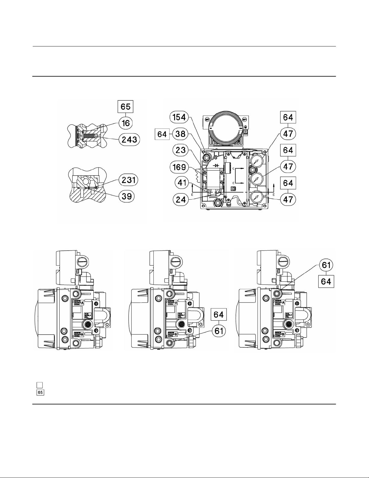
DVC6200p Digital Valve Controller
Parts
February 2021
Figure 7‐4. FIELDVUE DVC6205p Base Unit Housing Assembly (continued)
SST ONLY
SECTION C-C
SCALE 2 : 1
Instruction Manual
D103563X012
SECTION E-E
SCALE 2 : 1
DOUBLE‐ACTING SHOWN
DOUBLE‐ACTING DIRECT‐ACTING REVERSE‐ACTING
APPLY LUBRICANT, SEALANT, OR THREAD LOCK
APPLY LUBRICANT ON ALL O-RINGS UNLESS OTHERWISE SPECIFIED
GE40181
66

Instruction Manual
D103563X012
Figure 7‐4. FIELDVUE DVC6205p Base Unit Housing Assembly (continued)
DVC6200p Digital Valve Controller
Parts
February 2021
WALL MOUNTING
APPLY LUBRICANT, SEALANT, OR THREAD LOCK
APPLY LUBRICANT ON ALL O-RINGS UNLESS OTHERWISE SPECIFIED
GE40181
PIPE MOUNTING
67

DVC6200p Digital Valve Controller
Parts
February 2021
Figure 7‐5. FIELDVUE DVC6215 Remote Feedback Assembly
PARTS NOT SHOWN: 158
APPLY LUBRICANT/SEALANT
GE46670-B
HOUSING A
(USED FOR GX ACTUATOR)
Instruction Manual
D103563X012
SECTION A-A
PARTS NOT SHOWN: 158
APPLY LUBRICANT/SEALANT
GE40178-B
68
SECTION A-A
HOUSING B
(USED FOR ALL ACTUATORS EXCEPT GX)

DVC6200p Digital Valve Controller
Instruction Manual
D103563X012
Principle of Operation
February 2021
Appendix A Principle of OperationA‐A‐
Digital Valve Controller Operation
The DVC6200p digital valve controller has a single module base that may be easily replaced in the field without
disconnecting field wiring or tubing. The master module contains the following submodules: current‐to‐pneumatic
(I/P) converter, printed wiring board assembly, and pneumatic relay. The relay position is detected by sensing the
magnet on the relay beam via a detector on the printed wiring board. This sensor is used for the minor loop feedback
(MLFB) reading. The master module can be rebuilt by replacing the submodules. See figures A‐1 and A‐2.
Figure A‐1. FIELDVUE DVC6200p Digital Valve Controller Block Diagram
DIGITAL
SETPOINT
9–32 VOLT
FIELDBUS
VALVE TRAVEL FEEDBACK
SUPPLY
PRESSURE
VALVE AND ACTUATOR
AUXILIARY
TERMINALS
TERMINAL BOX
E1376
PRINTED
WIRING BOARD
DRIVE
SIGNAL
OUTPUT A
I/P
CONVERTER
PNEUMATIC
RELAY
OUTPUT B
VENT
The DVC6200p digital valve controller is a bus‐powered instrument that provides a control valve position in response
to a digital setpoint from the control room. The following describes a direct acting DVC6200p digital valve controller
mounted on a sliding-stem piston actuator, where the valve is closed with zero power to the instrument.
The setpoint is routed into the terminal box through a single pair of wires and then to the printed wiring board
assembly submodule where it is read by the microprocessor, processed by a digital algorithm, and converted into an
analog I/P drive signal.
As the setpoint increases, the drive signal to the I/P converter increases, increasing the I/P output pressure. The I/P
output pressure is routed to the pneumatic relay submodule. The relay is also connected to supply pressure and
amplifies the small pneumatic signal from the I/P converter. The relay accepts the amplified pneumatic signal and
provides two output pressures. With relay A, an increasing setpoint will produce increasing pressure at output A and
decreasing pressure at output B. With relay B an increasing setpoint will produce decreasing pressure at output B
69

DVC6200p Digital Valve Controller
Principle of Operation
February 2021
Instruction Manual
D103563X012
(output A is not available). With relay C an increasing setpoint will produce an increasing pressure on output A (output
B is not available). The output A pressure is used for double‐acting and single‐acting direct applications. The output B
pressure is used for double‐acting and single‐acting reverse applications.
Figure A‐2. FIELDVUE DVC6200p Digital Valve Controller Assembly
HOUSING
W9925‐1 profibus
TERMINAL BOX WITH COVER
PRINTED WIRING
BOARD ASSEMBLY
MODULE BASE ASSEMBLY
PNEUMATIC RELAY
I/P CONVERTER
GAUGES
COVER
As shown in figure A‐1, the increased output A pressure causes the actuator stem to move upward. The stem position
is sensed by the travel sensor. The stem continues to move upward until the correct stem position is attained. At this
point the printed wiring board assembly stabilizes the I/P drive signal. This prevents any further increase in the
pneumatic signal from the I/P converter.
As the digital setpoint decreases, the drive signal to the I/P converter submodule decreases, decreasing the I/P output
pressure. The pneumatic relay decreases the output A pressure and increases the output B pressure. The stem moves
downward until the correct position is attained. At this point the printed wiring board assembly stabilizes the I/P drive
signal. This prevents any decrease in the pneumatic signal from the I/P converter.
70

DVC6200p Digital Valve Controller
Instruction Manual
D103563X012
Appendix B Device Diagnostics8‐B‐B‐105.
Description of device related diagnosis
Unit_Diag_Bit(16) = "Error appears"
Unit_Diag_Bit(17) = "Error disappears"
Unit_Diag_Bit(35) = "Restart"
Unit_Diag_Bit(36) = "Coldstart"
Unit_Diag_Bit(37) = "Maintenance required"
Unit_Diag_Bit(39) = "Ident_Number violation"
Unit_Diag_Bit(40) = "Failure of the device"
Unit_Diag_Bit(41) = "Maintenance demanded"
Unit_Diag_Bit(42) = "Function Check"
Unit_Diag_Bit(43) = "Process nt rtn valid values"
Unit_Diag_Bit(55) = "Extension Available"
Device Diagnostics
February 2021
Extended Diagnostic Bytes - Manufacturer Specific
Unit_Diag_Bit(56) = "Dia Limits"
Unit_Diag_Bit(57) = "Dia Advisory"
Unit_Diag_Bit(58) = "Reserved"
Unit_Diag_Bit(59) = "Reserved"
Unit_Diag_Bit(60) = "Reserved"
Unit_Diag_Bit(61) = "Reserved"
Unit_Diag_Bit(62) = "Reserved"
Unit_Diag_Bit(63) = "Reserved"
Unit_Diag_Bit(64) = "Drive Current Alert"
Unit_Diag_Bit(65) = "Drive Signal Alert"
Unit_Diag_Bit(66) = "Program Memory Alert"
Unit_Diag_Bit(67) = "Static Memory Alert"
Unit_Diag_Bit(68) = "I/O Processor Alert"
Unit_Diag_Bit(69) = "Output Block Timeout"
Unit_Diag_Bit(70) = "Blocks Set To Default"
Unit_Diag_Bit(71) = "Travel Sensor Alert"
Unit_Diag_Bit(72) = "Port A Pressure Sensor Alert"
Unit_Diag_Bit(73) = "Port B Pressure Sensor Alert "
Unit_Diag_Bit(74) = "Supply Pressure Sensor Alert"
Unit_Diag_Bit(75) = "Temperature Sensor Alert"
Unit_Diag_Bit(76) = "Pressure Fallback"
Unit_Diag_Bit(77) = "Supply Pressure High"
Unit_Diag_Bit(78) = "Supply Pressure Low"
Unit_Diag_Bit(79) = "Temperature High"
71

DVC6200p Digital Valve Controller
Device Diagnostics
February 2021
Unit_Diag_Bit(80) = "Temperature Low"
Unit_Diag_Bit(81) = "Travel Deviation"
Unit_Diag_Bit(82) = "Travel Limit High High"
Unit_Diag_Bit(83) = "Travel Limit Low Low"
Unit_Diag_Bit(84) = "Travel Limit High"
Unit_Diag_Bit(85) = "Travel Limit Low"
Unit_Diag_Bit(86) = "Cycle Counter Alert"
Unit_Diag_Bit(87) = "Travel Accumulator Alert "
Unit_Diag_Bit(88) = "Travel Open"
Unit_Diag_Bit(89) = "Travel Closed"
Unit_Diag_Bit(90) = "Proximity High High"
Unit_Diag_Bit(91) = "Proximity High"
Unit_Diag_Bit(92) = "Proximity Low Low"
Unit_Diag_Bit(93) = "Proximity Low"
Unit_Diag_Bit(94) = "Auxiliary Terminal Shorted"
Unit_Diag_Bit(95) = "Calibration By Hand"
Unit_Diag_Bit(96) = "Calibration Automatic"
Unit_Diag_Bit(97) = "AI Hi Hi Limit Exceeded"
Unit_Diag_Bit(98) = "AI Hi Limit Exceeded"
Unit_Diag_Bit(99) = "AI Lo Lo Limit Exceeded"
Unit_Diag_Bit(100) = "AI Lo Limit Exceeded"
Unit_Diag_Bit(101) = "Reserved"
Unit_Diag_Bit(102) = "Reserved"
Unit_Diag_Bit(103) = "Reserved"
Instruction Manual
D103563X012
72

DVC6200p Digital Valve Controller
Instruction Manual
D103563X012
Blocks— Physical Block
February 2021
Appendix C BlocksC‐C‐
Physical Block
The physical block contains the hardware specific characteristics associated with a device; it has no input or output
parameters. The physical block monitors and controls the general operation of other blocks within the device. Most of
the physical block parameters are operational parameters that provide information about the instrument such as
identification, hardware information, available options, etc. and are read only. Configuration of the physical block
involves selecting features from those that are available and setting the mode.
Parameter List
D Read/Write Capability: RO - Read Only, RW - Read Write
D Mode: The block mode(s) required to write to the parameter
D Double indentation and shared Index Number indicates sub‐parameter.
Table C‐1. Physical Block Parameter Definitions
Label
PARAMETER_NAME
BLOCK_OBJECT
RESERVED
BLOCK_OBJECT
PARENT_CLASS
CLASS
DEV_REV
DEV_REV_COMP
DD_REVISION
Index
Number
RO /
Mode Valid Range
RW
0 RO -
0.1 250 Data Type: Unsigned8
0.2 1: Physical Block 1
1: Reserved
0.3
0.4 250
0.5 >0 1
0.6 1
0.7 0 Data Type: Unsigned16
2: Actuator
3-12: Reserved
-Continued-
2
Initial
Value
Data Type: DS‐32
First parameter of every block. Contains
characteristics of the block, eg. Block type and
profile number
Data Type: Unsigned8
Identifies the block.
Data Type: Unsigned8
Identifies which class the device belongs to.
Data Type: Unsigned8
Reserved
Data Type: Unsigned16
Contains information about the device's
revision. Increased when there is a new firmware
release.
Data Type: Unsigned16
Represents the lowest device revision which is
supported by the device.
Description
73

DVC6200p Digital Valve Controller
Blocks— Physical Block
February 2021
Table C‐1. Physical Block Parameter Definitions (Continued)
Label
PARAMETER_NAME
PROFILE
PROFILE_REVISION
EXECUTION_TIME
NUMBER_OF_PARAMETERS
ADDRESS_OF_VIEW_1
NUMBER_OF_VIEWS
Static Revision
ST_REV
Tag Description
TAG_DESC
Strategy
STRATEGY
Alert Key
ALERT_KEY
Target Mode
TARGET_MODE
Index
Number
RO /
RW
0.8
0.9
0.10 0 Data Type: Unsigned8
0.11 0x3c
0.12
0.13 0x01
1 RO 0 to 65535 0
2 RW ALL Null
3 RW ALL 0
4 RW ALL 0 to 255 0
5 RW ALL
Valid RangeMode
Octet 1: Number of PA
profiles within PI
Profile Class. Set to
0x40.
Octet 2:
0x01: Class A, all
standard params have
their own memory
place.
0x02: Class B, all
standard params have
their own memory
place.
0x81: Class A, all
standard params in 1
memory place.
0x82: Class B, all
standard params in 1
memory place.
253: Manufacturer
specific block
structures
Octet 1: Number
before the decimal
point
Octet 2: Number after
the decimal point
Octet 1 (MSB):
Slot
Octet 2 (LSB): Index of
View_1 parameter for
access.
7: OOS
3: Auto
-Continued-
Instruction Manual
Initial
Value
Data Type: Octet String
0x4002
0x0302
0x004C
Auto Target mode of the block
Profile Class given by PI, and description of
profile
Data Type: Unsigned16
Profile revision used for this device.
Data Type: Unsigned16
Number of used parameters in the block.
Data Type: Unsigned16
Address of View 1 parameter, see table C‐2.
Data Type: Unsigned8
Number of view objects of the block.
Data Type: Unsigned16
The revision level of the static data. Increments
by one each time a static parameter changes, or
a change of a table is accepted. Reset to 0 in
case of a cold start (ie if FACTORY_RESET = 1 is
set). Set to 1 if overflow.
Data Type: Octet String
The user description of the intended application
of the block.
Data Type: Unsigned16
User-specified value used in configuration or
diagnostics as a key in sorting block information
Data Type: Unsigned8
The identification number of the plant unit. This
information may be used in the host for sorting
alarms or events generated by blocks.
D103563X012
Description
74

Instruction Manual
D103563X012
Table C‐1. Physical Block Parameter Definitions (Continued)
Label
PARAMETER_NAME
Block Mode
MODE_BLK
ACTUAL 6.2
PERMITTED 6.3
NORMAL 6.4
Alarm Summary
ALARM_SUM
CURRENT 7.1
UNACKNOWLEDGED 7.2 0
UNREPORTED 7.3 0
DISABLED 7.4 0
Software Revision
SOFTWARE_REV
Hardware Revision
HARDWARE_REV
Manufacturer Id
DEVICE_MAN_ID
DEVICE_ID
DEVICE_SER_NUM
Index
Number
RO /
RW
6 RO
7 RO
8 RO
9 RO Factory Set
10 RO 0x13
11 RO Device ID
12 RO Null
Valid RangeMode
7: OOS
3: Auto
7: OOS
3: Auto
7: OOS
3: Auto
Octet 1
0 - 6: Reserved
7: Update Event - Set
after any STATIC
parameter is changed.
Octet 2: Reserved
-Continued-
Initial
Value
Auto
OOS + Auto
Auto
0
DVC6200p Digital Valve Controller
Blocks— Physical Block
February 2021
Description
Data Type: DS‐37
The actual, permitted, and normal modes.
Actual: The current mode of the block
Permitted: Allowed modes for TARGET_MODE
Normal: Desired operating mode
Data Type: DS‐42
Current alert status, unacknowledged states,
unreported states, and disabled states of the
alarms associated with the function block.
•Current active alerts cleared after 20s
(condensed status) or 10s (classic status)
•Unacknowledged, unreported, and disabled
not used.
Data Type: Visible string
Device's software revision
Data Type: Visible string
Device's hardware revision
Data Type: Unsigned16
Manufacturer identification number, used by an
interface device to locate the DD file for the
resource.
Data Type: Visible String
String containing the 16 character device ID
Of the form 0013DVCXXXXXXXXX, where
XXXXXXXXX = ELECTRONICS_SN
Data Type: Visible String
Serial number of the device. Set by factory.
75

DVC6200p Digital Valve Controller
Blocks— Physical Block
February 2021
Table C‐1. Physical Block Parameter Definitions (Continued)
Label
PARAMETER_NAME
DIAGNOSIS
Index
Number
RO /
RW
13 RO
Valid RangeMode
Octet 1
0-7: Reserved, set to 0
Octet 2
0-2: Reserved, set to 0
3: DIA_WARMSTART set after power up or
after executing
FACTORY_RESET =
2506 (A)
4: DIA_COLDSTART Set after executing
FACTORY_RESET = 1
(A)
5: DIA_MAINTENANCE
- Maintenance
required (R)
6: Reserved, set to 0
7: IDENT_NUMBER_
VIOLATION - set if
Ident_Number of the
running cyclic data
transfer and the value
of IDENT_NUMBER_
SELECTOR does not
match. If IDENT_
NUMBER_SELECTOR =
127 then this bit is
cleared (R)
Octet 3
0: DIA_
MAINTENANCE_ALARM
- Failure of device (R)
1: Reserved, set to 0
2: DIA_FUNCTION_
CHECK - Device is in
function check mode,
simulation or local
control (R)
3: Reserved, set to 0
4-7: Reserved, set to 0
Octet 4
0 - 6: Reserved
7: DIAGNOSIS_
EXTENSION available.
(R)
-Continued-
Initial
Value
0
Instruction Manual
D103563X012
Description
Data Type: Octet String
Used for all configuration, hardware, connection
failure or system problems in the device. If in
CONDENSED mode, not more than 1 bit is to be
set for a single diagnostic event. Only
CONDENSED mode is supported here.
(R): Indication remains active as long as the alert
is active
(A): Indication is set within 10s, and will be
cleared not later than 10s after the action is
completed
76

Instruction Manual
D103563X012
Table C‐1. Physical Block Parameter Definitions (Continued)
Label
PARAMETER_NAME
DIAGNOSIS_EXTENSION
Index
Number
RO /
RW
14 RO
Valid RangeMode
Octet 1
0: DIA_LIMITS - Limits
violation (R)
1: DIA_ADVISORY Advisory message
available (R)
Bits 2 - 7: Reserved
Octet 2
0: BM1 Drive Current Alert (R)
1: BM2 Drive Signal Alert (R)
2: BM3 - Program
Memory Alert (R)
3: BM4 - Static
Memory Alert (R)
4: BM5 I/O Processor Alert (R)
5: BM6 - Output Block
Timeout (R)
6: BM7 - Blocks Set To
Default (R)
7: BM8 Travel Sensor Alert (R)
Octet 3
0: BM9 - Port A
Pressure Sensor Alert
(R)
1: BM10 - Port B
Pressure Sensor Alert
(R)
2: BM11 - Supply
Pressure Sensor Alert
(R)
3: BM12 Temperature Sensor
Alert (R)
4: BM13 - Pressure
Fallback (R)
5: BM14 - Supply
Pressure High (R)
6: BM15 - Supply
Pressure Low (R)
7: BM16 Temperature
Octet 4
0: BM17 Temperature
Low (R)
1: BM18 Travel Deviation (R)
2: BM19 - Travel Limit
High High (R)
3: BM20 - Travel Limit
Low Low (R)
4: BM21 Travel Limit High (R)
5: BM22 - Travel Limit
Low (R)
6: BM23 - Cycle
Counter Alert (R)
7: BM24 - Travel
Accumulator Alert (R)
-Continued-
High (R)
DVC6200p Digital Valve Controller
Blocks— Physical Block
Initial
Value
0
Data Type: Octet String
Contains additional device alerts if
DIAGNOSIS_EXTENSION available bit is set in
DIAGNOSIS parameter
Octets 2 to 6 are related to the binary messages
in the Alarm Transducer block. The bits in Octets
2 to 6 will be set when the corresponding alert in
the Alarm TB is enabled and becomes active.
(R): Indication remains active as long as the alert
is active
(A): Indication is active within 10s, and will be
cleared not later than 10s after the action is
completed
Description
February 2021
77

DVC6200p Digital Valve Controller
Blocks— Physical Block
February 2021
Table C‐1. Physical Block Parameter Definitions (Continued)
Label
PARAMETER_NAME
DIAGNOSIS_EXTENSION (continued)
DIAGNOSIS_MASK
DIAGNOSIS_MASK_EXTENSION
Index
Number
RO /
RW
14 RO
15 RO
16 RO
Valid RangeMode
Octet 5
0: BM25 Travel Open (R)
1: BM26 Travel Closed (R)
2: BM27 - Proximity
High High (R)
3: BM28 Proximity High (R)
4: BM29 Proximity Low Low (R)
5: BM30 Proximity Low (R)
6: BM31 - Auxiliary
Terminal Shorted (R)
7: BM32 - Calibration
By Hand (R)
Octet 6
0: BM33 - Calibration
Automatic (R)
1: BM34 - AI Hi Hi
Limit Exceeded (R)
2: BM35 - AI Hi Limit
Exceeded (R)
3: BM36 - AI Lo Lo
Limit Exceeded (R)
4: BM37 - AI Lo Limit
Exceeded (R)
5 - 7: Reserved
See DIAGNOSIS,
parameter 13 for valid
Range
See DIAGNOSIS_
EXTENSION,
parameter 15 for valid
range
Initial
Value
0
0x00B80580
0x03FFFFFFFF
1F
Instruction Manual
D103563X012
Description
Data Type: Octet String
Contains additional device alerts if
DIAGNOSIS_EXTENSION available bit is set in
DIAGNOSIS parameter
Octets 2 to 6 are related to the binary messages
in the Alarm Transducer block. The bits in Octets
2 to 6 will be set when the corresponding alert in
the Alarm TB is enabled and becomes active.
(R): Indication remains active as long as the alert
is active
(A): Indication is active within 10s, and will be
cleared not later than 10s after the action is
completed
Data Type: Octet String
Definition of supported DIAGNOSIS information
bits. Set if the corresponding diagnosis is
supported.
Data Type: Octet String
Definition of supported DIAGNOSIS_EXTENSION
information bits. Set if the corresponding
diagnosis is supported.
DEVICE_CERTIFICATION
Write Lock
WRITE_LOCKING
78
17 Not used
0: Acyclic writes to all
parameters are
denied, except
WRITE_LOCKING,
18 RW ALL
TAB_ENTRY and
ACTUAL_POST_READ
_NUMBER parameter.
2457: All parameters
are writeable.
-Continued-
2457
Data Type: Unsigned16
Software write protection.

Instruction Manual
D103563X012
Table C‐1. Physical Block Parameter Definitions (Continued)
Label
PARAMETER_NAME
FACTORY RESET
DESCRIPTOR
Index
Number
RO /
RW
19 RW ALL
20 RW ALL null
Valid RangeMode
1: Reset parameters
to default values. The
setting of bus address
is not affected.
2: Reset informational
parameters. The
setting of bus address
is not affected.
3: Reset functional
parameters. The
setting of bus address
is not affected.
2506: Restart device.
Has the same effect as
power-cycling the
device. Only dynamic
parameters are reset.
2712: Reset bus
address to 126.
32768: Reset
Power_Up_Count to
0. Available to factory
only.
DVC6200p Digital Valve Controller
Blocks— Physical Block
Initial
Value
0
Data Type: Unsigned16
Allows a manual reset to be initiated. Several
degrees of reset are possible.
Note that writing some values may affect
communications.
Data Type: Octet String
User-defined text describing the device within
the application
Description
February 2021
DEVICE_MESSAGE
DEVICE_INSTAL_DATE
LOCAL_OP_ENA
IDENT_NUMBER_SELECTOR
HW_WRITE_PROTECTION
Data Type: Octet String
21 RW ALL null
22 RW ALL null
23 Not used
0: Profile specific id
number V3.x
1: Manufacturer
specific id number
24 RW ALL
25 Not used
V3.x
2 - 126: Reserved
127: Adaptation
mode, device is able
to communicate using
multiple id numbers
-Continued-
127
User-defined message describing the device
within the application or in the plant
Data Type: Octet String
Device installation date.
Data Type: Unsigned8
Selector for profile specific or manufacturer
specific identification number. Not affected by
FACTORY_RESET. Change of id number via this
parameter changes the characteristics of the
device's cyclic behavior, which is determined by
the associated GSD-file. The following
conditions apply:
1. The change is to be done when there is no
cyclic communication to the device.
2. Change to this parameter value during cyclic
communication to the device causes the
IDENT_NUMBER_VIOLATION bit of the
DIAGNOSIS parameter to be set. The cyclic data
transfer is not affected and the associated
Ident_Number of the device remains the same,
until either the cyclic transfer is aborted and
reinstalled, or a power down happens. During
the new re-establishment of the cyclic data
transfer the latest IDENT_NUMBER_SELECTOR
value and the associated Ident_Number is used.
3. Parameter cannot be modified when cyclic
data transfer is active. Response error code is
"Access, state conflict".
79

DVC6200p Digital Valve Controller
Blocks— Physical Block
February 2021
Table C‐1. Physical Block Parameter Definitions (Continued)
Label
PARAMETER_NAME
Feature
FEATURE
SUPPORTED 26.1 RO
ENABLED 26.2 RO
COND_STATUS_DIAG
Index
Number
RO /
RW
26
27 RW ALL
Valid RangeMode
Octet 1:
0: Diagnosis
Condensed_Status
supported
1: Diagnosis
Classic_Status
supported
2: Data exchange
broadcast supported
3: MS1 application
relationship supported
4: Profisafe
communication
supported
5-7: Reserved
Octets 2-4: Reserved
Octet 1:
0: Diagnosis
Condensed_Status
enabled
1: Diagnosis
Classic_Status enabled
2: Data exchange
broadcast enabled
3: MS1 application
relationship enabled
4: Profisafe
communication
enabled
5 - 7: Reserved
Octets 2-4: Reserved
0: Reserved
1: Condensed Status
and Diagnosis
2 - 255: Reserved
-Continued-
Initial
Value
0x01000000
0x01000000
1
Instruction Manual
D103563X012
Description
Data Type: DS-68
Indicates optional features implemented in the
device and the status of these features, whether
supported or not supported.
Data Type: Unsigned8
Indicates / configures the type of status and
diagnostic currently being active in the device
80

Instruction Manual
D103563X012
Table C‐1. Physical Block Parameter Definitions (Continued)
Label
PARAMETER_NAME
DIAG_EVEN_SWITCH
DIAG_STATUS_LINK 28.1 RW ALL
SLOT 28.2 RO ALL 0 0
INDEX (ABSOLUTE) 28.3 RO ALL 0 0
Reserved by PI 29-38
GLOBAL_STATUS
Reserved by PI 40-47
DEV_IDENT_NUMBER
Private Label Distributor
DISTRIBUTOR
Miscellaneous Options
MISC_OPTIONS
Electronics Serial Number
ELECTRONICS_SN
Field Serial Number
FIELD_SN
Index
Number
RO /
RW
28
39 RO
48 RO 0x1037
49 Not used
50 RO
51 RO Factory Set
52 RW ALL null
Valid RangeMode
STATUS (Bits 0 - 3):
0: GOOD - OK
1: GOOD maintenance required
2: GOOD maintenance
demanded
3: UNCERTAIN maintenance
demanded
4: BAD - maintenance
alarm
5: Uncertain - process
related, no
maintenance
6: BAD - process
related, no
maintenance
7: BAD - function check
/ local override
8: GOOD - function
check
DIAGNOSIS (Bits 4 - 7):
0: OK
1: DIA_MAINTENANCE
2: DIA_MAINTENANCE
_DEMANDED
3: DIA_MAINTENANCE
_ALARM
4:
DIA_INV_PRO_COND
5: DIA_FUNCTION_
CHECK
0: Failure
1: Maintenance
required
2: Function check
3: Limits
4: Advisory
Extended Parameters
0: Software Download
10: Travel Control
Capable
11: Pressure Control
Capable
12: Fallback Capable
-Continued-
Initial
Value
0
0x1C00
(Bits 10, 11
12)
DVC6200p Digital Valve Controller
Blocks— Physical Block
February 2021
Description
Data Type: Unsigned8
Allows mapping to DIAGNOSIS_EXTENSION.
Each byte corresponds to how each bit in
DIAGNOSIS_EXTENSION parameter will trigger
the corresponding bit in DIAGNOSIS parameter.
Byte to bit mapping in the same order.
Data Type: Unsigned8
Points to the next Diag_Event_Switch structure.
Data Type: Unsigned16
Information on Alarm Transducer Block Alarm's
Status
Data Type: Unsigned16
Device's manufacturer specific identification
number, provided by PNO during device
registration
Data Type: Unsigned32
Indicates which miscellaneous licensing options
are enabled.
Data Type: Visible String
Electronics serial number set by manufacturing.
Data Type: Visible String
Instrument serial number set in the field.
81

DVC6200p Digital Valve Controller
Blocks— Physical Block
February 2021
Table C‐1. Physical Block Parameter Definitions (Continued)
Label
PARAMETER_NAME
Time Since Reset
TIME_SINCE_RESET
POWER_UP_COUNT
STBY_SOFTWARE_REV
FB_AVAILABLE
DEVICE_TIME
Fraction of a minute 57.1 0-999 0
Fraction of an hour 57.2 0-59 0
Fraction of a day 57.3 0-23 0
Day of Week + Day of Month 57.3
Month 57.3 1-12 1
Year 57.3 84
DEVICE_ADDRESS
STACK_LIB_VERSION
Index
Number
RO /
Mode Range
RW
53 RO 0 - 0xFFFFFFFF 0
54 RO 0 - 0xFFFFFFFF 0
55 RO
0: AO
1: DO
2: AI
3: DI
56 RO
57 RW ALL 0
58 RW OOS 0-126 126
59 RO
4: PID
5: IS
6: OS
7: MAI
8: CS
9: LB
Upper 3 bits: 0 =
Sunday, 1=Monday …
6 = Saturday
Lower 5 bits: 1 … 31
Initial
Value
0x20F
1
Instruction Manual
D103563X012
Description
Data Type: Unsigned32
Number of seconds since the last time
DVC6200p was restarted. Restart due to power
up or restart command.
Data Type: Unsigned32
Number of power cycles since leaving factory.
Affected by FACTORY_RESET in the following
manner:
Reset default parameters (1): Resets to 1
Restart device (2506): Increment by 1
Reset Power_Up_Count (32768): Resets to 0
Data Type: Visible String
Device's standby software revision. Reserved for
future use.
Data Type: Octet String
Indicates which function blocks are available to
license in the firmware
Data Type: BinaryDate
Device date and time
Data Type: Unsigned16
Number of milliseconds
Data Type: Unsigned8
Minute
Data Type: Unsigned8
Hour
Data Type: Unsigned8
Upper 3 bits = Day of week
Lower 3 bits = Day of month
Data Type: Unsigned8
Month
Data Type: Unsigned8
Year
Data Type: Unsigned8
Indicates devices address. Only writeable during
device setup. Not affected by FACTORY RESET.
Data Type: Visible String
Identifies which version of Stack Library is
present in the device.
82

Instruction Manual
D103563X012
View Lists
View lists allow the values of a set of parameters to be accessed at the same time.
Table C‐2. Physical Block, View 1
Index Number Parameter
1 ST_REV
6.1 MODE_BLK.ACTUAL_MODE
6.2 MODE_BLK.PERMITTED_MODE
6.3 MODE_BLK.NORMAL_MODE
7.1 ALARM_SUM.CURRENT
7.2 ALARM_SUM.UNACKNOWLEDGED
7.3 ALARM_SUM.UNREPORTED
7.4 ALARM_SUM.DISABLED
13 DIAGNOSIS
DVC6200p Digital Valve Controller
Blocks— Physical Block
February 2021
83

DVC6200p Digital Valve Controller
Blocks— Transducer Block
February 2021
Instruction Manual
D103563X012
Transducer Block
The transducer block accepts a signal from an output block as a set point to position a valve using a pneumatic
actuator. Input to the transducer block is in percent. Closed is 0%, and open is 100%. The transducer block contains
setup and calibration information and can be tuned to closely match the actuator. Input characterization permits
modifying the overall characteristic of the instrument‐actuator‐valve combination in order to modify the installed gain
characteristic of the loop. The transducer block can also be used to perform instrument and valve diagnostics and
trigger performance alerts.
Parameter List
D Read/Write Capability: RO - Read Only, RW - Read Write
D Mode: The block mode(s) required to write to the parameter
D Protection Category: Indicates whether or not the parameter is writable while the PROTECTION parameter
is set to a particular level.
-N/A indicates a read‐only parameter that is never writable, regardless of the value of the PROTECTION parameter
-NONE indicates a read‐only parameter that is always writable, regardless of the value of the PROTECTION parameter
-CAL indicates a parameter that is only writable while the value of the PROTECTION parameter is “NONE”.
-SETUP indicates a parameter that is only writable while the value of the PROTECTION parameter is “NONE” or “CAL”.
-ALL indicates a parameter that is writable while the value of the PROTECTION parameter is “NONE”, “CAL”, or “SETUP & CAL”.
D Double indentation and shared Index Number indicates sub‐parameter
Table C‐3. Transducer Block Parameter Definitions
Label
PARAMETER_NAME
BLOCK_OBJECT
RESERVED
BLOCK_OBJECT
PARENT_CLASS
CLASS
DEV_REV
DEV_REV_COMP
Index
Number
RO /
Mode Range Default Value
RW
0 RO -
0.1 250
0.2 3: Transducer Block 3
1-4: Reserved
0.3
0.4
0.5 1
0.6 1
5: Actuator
6-127: Reserved
1: Reserved
2: Electro-pneumatic
3-127: Reserved
-Continued-
Protect
Category
Data Type: DS‐32
First parameter of every block.
Contains characteristics of the block,
eg. Block type and profile number
Data Type: Unsigned8
Reserved
Data Type: Unsigned8
Identifies the block.
Data Type: Unsigned8
5
2
Identifies which class the device
belongs to.
Data Type: Unsigned8
Identifies the type of device.
Data Type: Unsigned16
Contains information about the
device's revision. Increased when
there is a new firmware release.
Data Type: Unsigned16
Represents the lowest device
revision which is supported by the
device.
Description
84

Instruction Manual
D103563X012
Table C‐3. Transducer Block Parameter Definitions (Continued)
Label
PARAMETER_NAME
DD_REVISION
PROFILE
PROFILE_REVISION
EXECUTION_TIME
NUMBER_OF_PARAMETERS
ADDRESS_OF_VIEW_1
NUMBER_OF_VIEWS
Static Revision
ST_REV
Tag Description
TAG_DESC
Strategy
STRATEGY
Alert Key
ALERT_KEY
Target Mode
TARGET_MODE
Index
Number
RO /
RW
0.7 0 Data Type: Unsigned16
Octet 1:
Number of PA profiles
within PI Profile Class. Set
to 0x40.
Octet 2:
0x01: Class A, all standard
params have their own
memory place.
0x02: Class B, all standard
0.8
0.9
0.10 0
0.11 0x86
0.12
0.13 0x01
1 RO 0 to 65535 0 N/A
2 RW ALL NULL SETUP
3 RW ALL 0 SETUP
4 RW ALL 0 to 255 0 SETUP
5 RW ALL
params have their own
memory place.
0x81: Class A, all standard
params in 1 memory
place.
0x82: Class B, all standard
params in 1 memory
place.
253: Manufacturer
specific block structures
Octet 1:
Number before the
decimal point.
Octet 2:
Number after the decimal
point.
Octet 1 (MSB):
Slot
Octet 2 (LSB):
Index of View_1
parameter for access.
7: OOS
3: AUTO
-Continued-
Default ValueRangeMode
0x4002
0x0302
0x0896
7 N/A
DVC6200p Digital Valve Controller
Blocks— Transducer Block
February 2021
Protect
Category
Data Type: Octet String
Profile Class given by PI, and
description of profile.
Data Type: Unsigned16
Profile revision used for this device.
Data Type: Unsigned16
Number of used parameters in the
block.
Data Type: Unsigned16
Address of View 1 parameter, see
table C‐4.
Data Type: Unsigned8
Number of view objects of the block.
Data Type: Uint16
The revision level of the static data.
Increments by one each time a static
parameter changes, or a change of a
table is accepted. Reset to 0 in case
of a cold start (ie if FACTORY_RESET
= 1 is set). Set to 1 if overflow.
Data Type: String
The user description of the intended
application of the block.
Data Type: Uint16
User-specified value used in
configuration or diagnostics as a key
in sorting block information.
Data Type: Uint8
The identification number of the
plant unit. This information may be
used in the host for sorting alarms or
events generated by blocks.
Data Type: Uint8
The requested block mode.
Description
85

DVC6200p Digital Valve Controller
Blocks— Transducer Block
February 2021
Table C‐3. Transducer Block Parameter Definitions (Continued)
Label
PARAMETER_NAME
Block Mode
MODE_BLK
ACTUAL 6.1 N/A
PERMITTED 6.2 OOS + Auto
NORMAL 6.3 AUTO
Alarm Summary
ALARM_SUM
CURRENT 7.1 0
UNACKNOWLEDGED 7.2 0 Not used
UNREPORTED 7.3 0 Not used
DISABLED 7.4 0 Not used
Reserved by PI 8
ACT_STROKE_TIME_DEC
ACT_STROKE_TIME_INC
Reserved by PI 11-16
TAB ENTRY
TAB_X_Y_VALUE
TAB_MIN_NUMBER
TAB_MAX_NUMBER
TAB_ACTUAL_NUMBER
DEADBAND
DEVICE_CALIB_DATE
Index
Number
RO /
RW
6 RO
7 RO
9 RO ALL 0 N/A Not used
10 RO ALL 0 N/A Not Used
17 RW OOS 1 to 21 1 SETUP
18 RW OOS
19 RO 2 SETUP
20 RO 21 SETUP
21 RO 2 to 21 2 SETUP
22 RW OOS 0 N/A Not used
23 RW OOS NULL SETUP
7: OOS
3: AUTO
Octet 1:
0 - 6: Reserved
7: Update Event - Set
after any STATIC
parameter is changed.
Octet 2: Reserved
1-4: (Float) X_VALUE
5-8: (Float) Y_VALUE
-Continued-
Default ValueRangeMode
- SETUP
Protect
Category
N/A
N/A
Instruction Manual
D103563X012
Description
Data Type: DS‐69
The actual, target, permitted, and
normal modes.
Actual: The current mode of the
block
Permitted: Allowed modes for
TARGET_MODE
Normal: Desired operating mode
Data Type: DS‐42
Current alert status,
unacknowledged states, unreported
states, and disabled states of the
alarms associated with the function
block.
Data Type: Octet String
Current active alerts. Cleared after
20s (condensed status) or 10s
(classic status).
Data Type: Unsigned 8
Identifies which element of the table
is in the TAB_X_Y_VALUE parameter
currently. Used to read or write
value to the table element.
This parameter is never protected by
any write locking mechanism.
Data Type: Float
Contains one value couple of the
table. Writes to this parameter must
be preceded by a valid
TAB_OP_CODE.
Notes: -25% to 125%. Each X value
must be > previous value, each Y
value must be > previous value.
Checked when TAB_OP_CODE = 3 is
issued. Up to 21 X_VALUEs and 21
Y_VALUEs
Data Type: Unsigned 8
Minimum number of table entries
required to implement the table.
Data Type: Unsigned 8
Maximum number of table entries
stored.
Data Type: Unsigned 8
Actual number of entries in the
table. Calculated after the table is
stored in the device.
Data Type: Octet String
Date of last calibration of the device.
If calibration is executed from AUX
terminals, this will be the timestamp
of calibration completion.
86

DVC6200p Digital Valve Controller
Instruction Manual
D103563X012
Table C‐3. Transducer Block Parameter Definitions (Continued)
Label
PARAMETER_NAME
DEVICE_CONFIG_DATE
LIN_TYPE
Reserved by PI 26-31 N/A
RATED_TRAVEL
SELF_CALIB_CMD
Index
Number
RO /
RW
24 RW OOS NULL SETUP
0: No linearization (linear)
1: Linearization table
25 RW OOS
32 RW OOS -25% to 125% 100 NONE
33 RW
240: Equal percentage
241: Quick opening
Others: Reserved
0: None
1: Reserved
2: Start self calibration
7: Reset "total valve travel
limit exceeded"
CB_TOT_VALVE_TRAV
and reset "Accumulated
valve travel"
TOTAL_VALVE_TRAVEL
10: Reserved
11 = Start self calibration
Extended
12 = Start manual
calibration
14 = Mark full closed
15 = Mark full open
16 = Manual calibration
final
18 = Execute Tuner
19 = Execute Tuner
(Graphite Packing)
20 = Execute Tuner
(Booster)
21 = Execute Tuner
(Graphite Packing &
Booster)
22 = Clear
SELF_CALIB_STATUS
255: Abort
-Continued-
Default ValueRangeMode
0 SETUP
0 CAL
Category
Blocks— Transducer Block
Protect
Data Type: Octet String
Date of last configuration of the
device.
Data Type: Unsigned8
Type of linearization.
Data Type: Float
Nominal stroke of the valve in units
same as that of OUT_SCALE. This
parameter is for informational
purposes only and has no effect on
the servo control.
Data Type: Unsigned8
Initiate calibration or tuner
procedure.
Description
February 2021
87

DVC6200p Digital Valve Controller
Blocks— Transducer Block
February 2021
Table C‐3. Transducer Block Parameter Definitions (Continued)
Label
PARAMETER_NAME
SELF_CALIB_STATUS
SERVO_GAIN_1
SERVO_RATE_1
SERVO_RESET_1
SETP_CUTOFF_DEC
SETP_CUTOFF_INC
Reserved by PI 40-44 NA N/A
TOTAL_VALVE_TRAVEL
TOT_VALVE_TRAVEL_LIM
TRAVEL_LIMIT_LOW
TRAVEL_LIMIT_UP
Index
Number
RO /
RW
0: Undetermined
1: Reserved
2: Aborted
3: Reserved
4: Error in mechanical
system (pressure
problem)
5-10: Reserved
12-127: Reserved
128: Self-calibration in
progress
129: Manual calibration in
progress
34 RO
35 RW ALL 0 <= value <= 32768 4.4 SETUP
36 RW ALL 0 <= value <= 32768 3 SETUP
37 RW ALL
38 RW OOS -25% to 125% 0.50% SETUP
39 RW OOS -25% to 125% 99.50% SETUP
45 RO NA N/A
46 RW ALL >=0% 1,000,000% SETUP
47 RW OSS
49 RW OOS
130: Quick Setup in
progress (If initiated from
AUX terminals)
131: tuner active
132: tuner error (no
movement)
133: tuner error
(Accessories unstable)
134: tuner error (Other)
135: Self-calibration error
(Other)
136: Aborted from AUX
terminals
254: Successful
255: No valid data (bad
sensor reading)
0 <= value <= 32768,
= 0 causes wind down
AO.OUT_SCALE.EU_AT_
0%-10% to
AO.OUT_SCALE.EU_AT_
100%+10%
AO.OUT_SCALE.EU_AT_
0%-10% to
AO.OUT_SCALE.EU_AT_
100%+10%
-Continued-
Default ValueRangeMode
0 N/A
9.4 SETUP
0% SETUP
100% SETUP
Category
Protect
Instruction Manual
D103563X012
Description
Data Type: Unsigned8
Result or status of the calibration
procedure. Initiating a new tuner or
calibration command will clear the
current bits.
Note: if the status is 'self-calibration
in progress' while power is cut off,
upon power being re-applied, this
parameter will show its last stored
value prior to the start of calibration.
Data Type: Float
Proportional gain. Used for travel
control only.
Data Type: Float
Derivative gain. Used for travel
control only.
Data Type: Float
Integral gain. Used for travel control
only. If set to 0, will cause integrator
to wind down.
Data Type: Float
Travel cutoff low
Data Type: Float
Travel cutoff high
Data Type: Float
Accumulated travel in %.
Data Type: Float
Limit for TOTAL_VALVE_TRAVEL in
%.
Data Type: Float
Lower limit of valve position in
percent of travel span,
corresponding to OUT_SCALE.
Data Type: Float
Upper limit of valve position in
percent of travel span,
corresponding to OUT_SCALE.
88

Instruction Manual
D103563X012
Table C‐3. Transducer Block Parameter Definitions (Continued)
Label
PARAMETER_NAME
TRAVEL_RATE_DEC
TRAVEL_RATE_INC
VALVE_MAINT_DATE
SERVO_GAIN_2
SERVO_RATE_2
SERVO_RESET_2
TAB_OP_CODE
Index
Number
RO /
RW
49 RW ALL 0 <= value <= 32768 0 NONE
50 RW ALL 0 <= value <= 32768 0 NONE
51 RW ALL Null CAL
52 N/A Not used
53 N/A Not used
54 N/A Not used
0: Not initialized
1: New operation
characteristic, first value
(TAB_ENTRY=1)
2: Reserved
55 RW OOS
3: Last value, end of
transmission, check
table, swap the old curve
with the new curve and
update
TAB_ACTUAL_NUMBER
4 - 6: Reserved
-Continued-
Default ValueRangeMode
0 SETUP
DVC6200p Digital Valve Controller
Blocks— Transducer Block
February 2021
Protect
Category
Data Type: Float
Closing time of the valve in seconds.
Controls how fast TRAVEL_TARGET
changes in response to
POSITIONING_VALUE. Example: If
the value of this parameter is
10secs, the valve will close at the
rate of 10%/sec. A value of 0 disables
rate limiting.
Data Type: Float
Opening time of the valve in
seconds. Controls how fast
TRAVEL_TARGET changes in
response to POSITIONING_VALUE.
Example: If the value of this
parameter is 10secs, the valve will
open at the rate of 10%/sec. A value
of 0 disables rate limiting.
Data Type: Octet String
Date of last valve maintenance
Data Type: Unsigned8
Controls the transaction of the
characterization table.
It is possible to read a table or parts
of the table without start and stop
interaction (TAB_OP_CODE 1 and 3).
The start is indicated by setting
TAB_ENTRY to 1.
Description
89

DVC6200p Digital Valve Controller
Blocks— Transducer Block
February 2021
Table C‐3. Transducer Block Parameter Definitions (Continued)
Label
PARAMETER_NAME
TAB_STATUS
POSITIONING_VALUE
VALUE
STATUS
Index
Number
RO /
RW
0: Not initialized
1: Good (new table is
valid)
2: Not monotonous
increasing (old table is
valid)
3: Reserved
4: Not enough values
transmitted (old table is
valid)
5: Too many values
transmitted (old table is
valid)
6 - 7: Reserved
8: Table is currently
loaded, set after
TAB_OP_CODE=1 and
before TAB_OP_CODE=3
(Additional access to
table not valid, old values
are valid)
9: Sorting and checking
of Table (Additional
56 RO
57 RO N/A
57.1 -25% to 125% 0
57.2 0
access to table not valid,
old values are valid)
10-19: Reserved
20: Not monotonous
increasing (table is not
initialized)
21: Reserved
22: Not enough values
transmitted (table is not
initialized)
23: Too many values
transmitted (table is not
initialized)
24 - 25: Reserved
26: Table is currently
loaded, set after
TAB_OP_CODE=1 and
before TAB_OP_CODE=3
(Additional access to
table not valid, table is
not initialized)
27: Sorting and checking
of Table (Additional
access to table not valid,
table is not initialized)
-Continued-
Default ValueRangeMode
0 N/A
Protect
Category
Instruction Manual
D103563X012
Description
Data Type: Unsigned8
Indicates the status of the
characterization table.
Data Type: 101
The actual command variable for the
device in units of OUT_SCALE, in
other words, setpoint in units of
OUT_SCALE, usually in percent.
Status BAD will drive the actuator to
the fail-safe position defined by
ACTUATOR_ACTION.
Data Type: Float
Physical target, or % of travel or
pressure range. Written by AO
channel 0x0839.
Data Type: Unsigned8
Indicates validity of VALUE, set by
out block OUT.STATUS..
90

DVC6200p Digital Valve Controller
Instruction Manual
D103563X012
Table C‐3. Transducer Block Parameter Definitions (Continued)
Label
PARAMETER_NAME
FEEDBACK_VALUE
VALUE
STATUS
VALVE_MAN
ACTUATOR_MAN
VALVE_TYPE
ACTUATOR_TYPE
ACTUATOR_ACTION
VALVE_SER_NUM
ACTUATOR_SER_NUM
ADD_GEAR_SER_NUM
ADD_GEAR_MAN
ADD_GEAR_ID
ADD_GEAR_INST_DATE
Reserved by PI 70-79 N/A
FINAL_POSITION_VALUE
Travel (Decharacterized)
VALUE
Travel Status (Decharacterized)
STATUS
Index
Number
RO /
RW
58 RO >=0 0 N/A
58.1 -25% to 125% 0
58.2 0
59 RW ALL Null SETUP
60 RW ALL Null SETUP
0: Sliding stem
61 RW ALL
62 RO
63 RW ALL
64 RW ALL NULL SETUP
65 RW ALL NULL SETUP
66 RW ALL NULL SETUP
67 RW ALL NULL SETUP
68 RW ALL NULL SETUP
69 RW ALL NULL SETUP
1: Part-turn rotary valve
2: Multi-turn rotary valve
0: Electro-pneumatic
1 - 3: Reserved
0: Not initialized
1: Opening (100%)
2: Closing (0%)
3: None / remains in
actual position
Default ValueRangeMode
0 SETUP
0 SETUP
0 SETUP
Category
Extended Parameters
80 RO N/A
80.1 -25 to 125% 0 N/A
80.2 0 N/A
-Continued-
Blocks— Transducer Block
Protect
Data Type: 101 The actual position
of the device in units of OUT_SCALE.
Controls AI channel 0x083A.
Data Type: Float
Physical position.
Data Type: Unsigned8
Indicates validity of VALUE.
Data Type: Octet String
Name of Valve Manufacturer.
Data Type: Octet String
Name of Actuator Manufacturer.
Data Type: Unsigned8
Type of valve.
Data Type: Unsigned8
Type of actuator.
Data Type: Unsigned8
Fail-safe position of the valve
assembly.
Data Type: Octet String
Serial number of the valve.
Data Type: Octet String
Serial number of the actuator.
Data Type: Octet String
Serial number of the additional
component (eg booster) mounted
between actuator and valve.
Data Type: Octet String
Manufacturer name of the additional
component (eg booster) mounted
between actuator and valve.
Data Type: Octet String
Manufacturer specific type
identification of the additional
component (eg booster) mounted
between the actuator and valve.
Data Type: Octet String
Installation date of the additional
component (eg booster) mounted
between actuator and valve.
Data Type: 101
Characterized Valve travel in percent
or characterized percent of pressure
range.
Data Type: Float
% of travel or pressure range,
controls AI channel 0x0850.
Data Type: Unsigned8
Indicates the validity of VALUE.
Description
February 2021
91

DVC6200p Digital Valve Controller
Blocks— Transducer Block
February 2021
Table C‐3. Transducer Block Parameter Definitions (Continued)
Label
PARAMETER_NAME
SETPOINT_D
VALUE
STATUS
TRAVEL_D
Travel (D)
VALUE
Travel(D) Status
STATUS
TRAVEL.TARGET
VALUE
STATUS
SUPPLY_PRESSURE
Supply Pressure
VALUE
Supply Pressure Status
STATUS
PRESSURE_A
Pressure A
VALUE
Pressure A Status
STATUS
PRESSURE_B
Pressure B
VALUE
Pressure B Status
STATUS
PRESSURE_DIFF
Pressure Differential
VALUE
Pressure Differential Status
STATUS
Index
Number
RO /
RW
81 RO N/A
0 = closed
81.1 N/A
81.2 N/A N/A
82 N/A
82.1 RO
82.2 RO N/A
83 N/A
83.1 RO -25% to 125%
83.2 RO Data Type: UINT8
84
84.1 RO N/A
84.2 RO N/A
85
85.1 RO N/A
85.2 RO N/A
86
86.1 RO N/A
86.2 RO N/A
87
87.1 RO N/A
87.2 RO N/A
1 = open
5,10,15.. = %
0 = closed
1 = open
5,10,15.. = %
-Continued-
Instruction Manual
D103563X012
Default ValueRangeMode
N/A
N/A
Protect
Category
Data Type: 101
Characterized Valve travel in percent
or characterized percent of pressure
range.
Data Type: Unsigned8
Discrete value of setpoint. Only
values of 0, 1, or increments of 5 up
to, and including 100 are allowed.
Written by DO channel 0x0851.
Data Type: Unsigned8
Indicates validity of value, set by out
block OUT.STATUS.
Data Type: Unsigned8
Discrete value of travel. Only values
of 0, 1, or increments of 5 up to , and
including 100 are allowed. Controls
DI channel 0x0852.
Data Type: Unsigned8
Indicates validity of value.
Data Type: 101
When the digital valve controller is
NOT in DO control, this parameter
takes its update from the
POSITIONING_VALUE. When the
digital valve controller is in DO
control, this parameter takes its
input from SETPOINT_D.
Data Type: Float
Physical target in % of travel or %
of pressure range. This is post
characterization. Controls AI
channel 0x0853.
Data Type: DS‐65
VALUE is pressure of air supply,
controls AI channel 0x0854. STATUS
indicates the validity of VALUE.
Data Type: DS‐65
Pressure of primary air output,
controls AI channel 0x0855.
STATUS Indicates the validity of
VALUE.
Data Type: DS‐65
VALUE is the Pressure on secondary
output, controls AI channel 0x0856.
STATUS indicates the validity of
VALUE.
Data Type:
VALUE is the difference between
PRESSURE_A and PRESSURE_B,
controls AI channel 0x0857.
STATUS indicates the validity of
VALUE.
Description
92
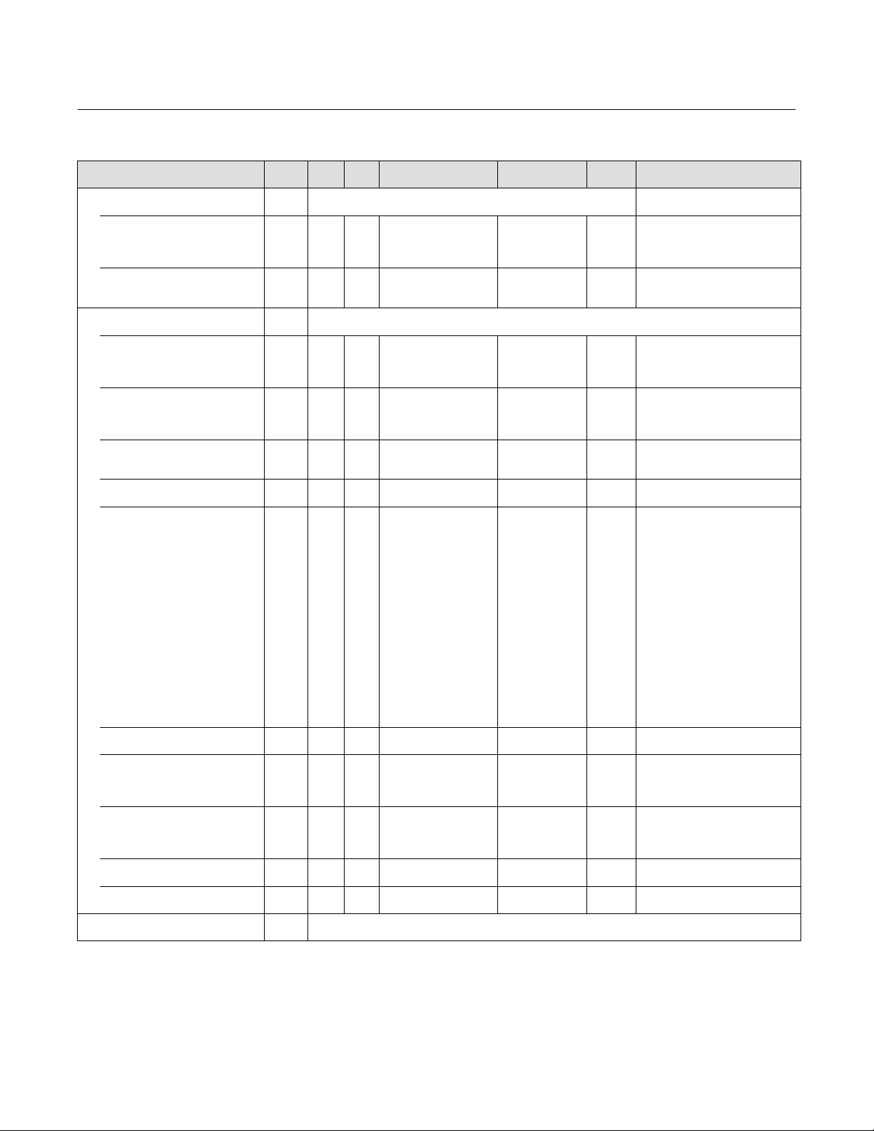
Instruction Manual
D103563X012
Table C‐3. Transducer Block Parameter Definitions (Continued)
Label
PARAMETER_NAME
Travel Pressure Control
TVL_PRESS_CONTROL
Travel/Pressure Select
TVL_PRESS_SELECT
Travel/Pressure State
TVL_PRESS_STATE
Basic Setup
BASIC_SETUP
Actuator Style
ACTUATOR_STYLE
Zero Power Condition
ZERO_PWR_COND
Travel Sensor Motion
TRAVEL_SENSOR_MOTION
Feedback Connection
FEEDBACK_CONN
Relay Type
RELAY_TYPE
Maximum Supply Pressure
MAX_SUPP_PRESS
Pressure Range Hi
PRESS_RANGE_HI
Pressure Range Lo
PRESS_RANGE_LO
Travel Tuning Set
TVL_TUNING_SET
Pressure Tuning Set
PRESS_TUNING_SET
TRAVEL_CAL
Index
Number
RO /
RW
88
1=Travel
88.1 RW ALL
88.2 RO N/A
89
89.1 RW OOS
89.2 RW OOS
89.3 RW OOS
89.4 RW OOS
89.5 RW OOS
89.6 RW ALL > 0, < = 150 35 psig SETUP Data Type: Float
89.7 RW OOS > 0, < = 150 15.0 psig SETUP
89.8 RW OOS > = 0, < = 150 3.0 psig SETUP
89.9 RW ALL
89.10 RW ALL
90
2=Pressure
3=TVL/PRESS Auto Recv
4=TVL/PRESS Man Recv
1=Travel
2=Pressure
1=Spring & Diaphragm
2=Piston‐Dbl w/o Spring
3=Piston‐Dbl w/Spring
4=Piston Sgl w/Spring
1=Valve Closed
2=Valve Open
1 = Counter Clockwise /
Towards Top of
Instrument
0x40-0x7F = SensorX
1=Relay A or C‐‐Double or
Single Direct
2=Relay B‐‐Single Reverse
5=Relay C‐Special App.
‐‐Single Direct
6=Relay B‐Special App.
‐‐Single Reverse
9=Lo‐Bleed Relay A or
C‐‐Double or Single
Direct
10=Lo‐Bleed Relay B‐‐
Single Reverse
13=Lo‐Bleed Relay C‐
Special App.‐‐Single
Direct
10=Lo‐Bleed Relay
B‐Special App.‐-Single
Reverse
1=B, 2= C, ...12=M
23=X
1=B, 2=C, ...12= M
23=X
-Continued-
DVC6200p Digital Valve Controller
Blocks— Transducer Block
Default ValueRangeMode
1 SETUP
N/A N/A
1 SETUP Data Type: Enum
1 SETUP
1 SETUP Data Type: Enum
0x40 SETUP Data Type: Enum
1 SETUP
2 SETUP
2 SETUP
Protect
Category
Data Type: Enum
Selects whether travel sensor or port
A pressure is used for feedback.
Data Type: Enum
Indicates which sensor is used for
feedback.
Data Type: Enum
Identifies whether the valve is open
or closed when instrument power is
lost.
Data Type: Enum
Note:
Bit 0: Direct
Bit 1: Reverse
Bit 2: Special App
Bit 3: Lo-Bleed
Data Type: Float
Defines pressure corresponding to
max pressure in pressure control
mode.
Data Type: Float
Defines pressure corresponding to
minimum pressure in pressure
control mode.
Data Type: Enum
Letter (B through M or X)
Data Type: Enum
Letter (B through M or X)
February 2021
Description
93

DVC6200p Digital Valve Controller
Blocks— Transducer Block
February 2021
Table C‐3. Transducer Block Parameter Definitions (Continued)
Label
PARAMETER_NAME
Travel Count
TVL_COUNT
Travel Hi Calibration
TVL_HI_CAL
Travel Lo Calibration
TVL_LO_CAL
Travel Fac Hi
TVL_FAC_HI
Travel Fac Lo
TVL_FAC_LO
Travel IP Bias
TVL_IP_BIAS
Travel MLFB Bias
TVL_MLFB_BIAS
Last Calibration Type
TVL_CAL_TYPE
SELF_CALIB_PROG
TRAVEL_TUNE
Travel Integral Enable
TVL_INTEG_ENABLE
Travel Integral Limit Hi
TVL_INTEG_LIM_HI
Travel Integral Limit Lo
TVL_INTEG_LIM_LO
Travel Integral Dead Zone
TVL_INTEG_DEADZ
Travel MLFB Gain
TVL_MLFB_GAIN
PRESS_CAL
Supply Pressure Scale
SUPP_PRESS_SCALE
Supply Pressure Offset
SUPP_PRESS_OFFSET
Pressure A Scale
PRESS_A_SCALE
Pressure A Offset
PRESS_A_OFFSET
Pressure B Scale
PRESS_B_SCALE
Pressure B Offset
PRESS_B_OFFSET
Pressure IP Bias
PRESS_IP_BIAS
Pressure MLFB Bias
PRESS_MLFB_BIAS
PRESS_TUNE1
Pressure Cutoff Hi
PRESS_CUTOFF_HI
Index
Number
RO /
RW
90.1 RO N/A
90.2 RW OOS
90.3 RW OOS
90.4 RO N/A Set by Factory N/A
90.5 RO N/A Set by Factory N/A
90.6 RW OOS 0% - 100% 70% CAL Data Type: Float
90.7 RW OOS 0 - 100% 50% CAL Data Type: Float
90.8 RW OOS
91 RO 0 N/A
92
92.1 RW ALL
92.2 RW ALL 0% - 100% 30% SETUP
92.3 RW ALL -100% - 0% -30% SETUP
92.4 RW ALL 0% - 2% 0.25% SETUP
92.5 RW ALL 0 <= value <= 32768 35 SETUP Data Type: Float
93
93.1 RW OOS 0 to 32768.0 CAL Data Type: Float
93.2 RW OOS 0 to 16383 CAL Data Type: Uint16
93.3 RW OOS 0 to 32768.0 CAL Data Type: Float
93.4 RW OOS 0 to 16383 CAL Data Type: Uint16
93.5 RW OOS 0 to 32768.0 CAL Data Type: Float
93.6 RW OOS 0 to 16383 CAL Data Type: Uint16
93.7 RW OOS 0-100% 70% CAL Data Type: Float
93.8 RW OOS 0-100% 50% CAL Data Type: Float
94
94.1 RW ALL -25 -125% 99.50% SETUP
TVL_FAC_LO <= value <=
TVL_FAC_HI
TVL_FAC_LO <= value <=
TVL_FAC_HI
0: Not Calibrated
1: Single Point Calibration
2: Auto Calibration
3: Manual Calibration
1=Off
2=On
-Continued-
Instruction Manual
Default ValueRangeMode
2 SETUP Data Type: Enum
Protect
Category
CAL
CAL
CAL
Data Type: Unsigned16
Raw feedback from pot A/D.
Data Type: Unsigned16
Valve travel in A/D counts when
I/P drive is at maximum.
Data Type: Unsigned16
Valve travel in A/D counts when
I/P drive is at zero.
Data Type: Uint16
Maximum value of travel sensor
counts. Set at factory.
Data Type: Uint16
Minimum value of travel sensor
counts. Set at factory.
Data Type: Enum
What was the last calibration done?
Data Type: UINT8
Indicates the progress of self
calibration.
Data Type: Float
Upper limit to the integrator output.
Data Type: Float
Lower limit to the integrator output
Data Type: Float
Window around the Primary
Setpoint in which the integral action
is disabled.
Data Type: Float
0.5% hysteresis on leaving cutoff.
D103563X012
Description
94

Instruction Manual
D103563X012
Table C‐3. Transducer Block Parameter Definitions (Continued)
Label
PARAMETER_NAME
Pressure Cutoff Lo
PRESS_CUTOFF_LO
Pressure Proportional Gain
PRESS_PROP_GAIN
Pressure Integral Gain
PRESS_INTEG_GAIN
Pressure Rate Gain
PRESS_RATE_GAIN
Temperature
TEMPERATURE
VALUE
STATUS
Travel Deviation
TRAVEL_DEVIATION
VALUE
STATUS
Drive Signal
DRIVE_SIGNAL
VALUE
STATUS
Drive Current
DRIVE_CURRENT
MLFB
MLFB
Cycle Count
CYCLE_COUNT
Temperature Units
TEMPERATURE_UNITS
Pressure Units
PRESSURE_UNITS
Travel Units
TVL_UNITS
Length Units
LENGTH_UNITS
Area Units
AREA_UNITS
Spring Rate Units
SPRING_RATE_UNITS
Index
Number
RO /
RW
94.2 RW ALL -25 -125% 0.50% SETUP
94.3 RW ALL > = 0, < 32 2.2 SETUP
94.4 RW ALL > = 0, < 32 0.1 SETUP
94.5 RW ALL > = 0, < = 512 0 SETUP
95
95.1 RO
95.2 RO N/A
96
96.1 RO N/A
96.2 RO N/A
97
97.1 RO 0 to 100% N/A
97.2 RO N/A
98 RO N/A 0 to 100% N/A Data Type: Float
99 RO N/A
100 RW ALL
101 RW ALL
102 RW ALL
103 RW ALL
104 RW ALL
105 RW ALL
106 RW ALL
> -76 F < 257 F or
equivalent in other units
-100% to 100% (when
device not in cutoff)
Write: Anything
Read: Actual
C=1001
F=1002
kPa=1133
bar=1137
psig=1143
inHg=1155
inH2O=1146
2
=1145
Kg/cm
cm=1012
mm=1013
in=1019
deg=1005
cm=1012
mm=1013
in=1019
cm2=1025
2
=1027
mm
2
=1030
in
N/m=1165
lb/in=1596
-Continued-
DVC6200p Digital Valve Controller
Blocks— Transducer Block
Default ValueRangeMode
N/A
C SETUP Data Type: Unsigned16
kPa SETUP Data Type: Unsigned16
mm SETUP
mm SETUP Data Type: Unsigned16
2
cm
N/m SETUP Data Type: Unsigned16
Protect
Category
Data Type: Float
0.5% hysteresis on leaving cutoff.
Data Type: Float
Proportional gain
Data Type: Float
Integral resets per second
Data Type: Float
Derivative gain
Data Type: Float
Electronics temperature - Controls
AI channel 0x085F.
Data Type: Unsigned8
Indicates validity of VALUE.
Data Type: Float
Absolute value of
FEEDBACK_VALUE(58) in % TRAVEL_TARGET(85). Controls AI
channel 0x0860.
Data Type: Unsigned8
Indicates validity of VALUE.
Data Type: Float
Controls AI channel 9
Data Type: Float Drive to I/P,
controls AI channel 0x0861.
Data Type: Unsigned8
Indicates validity of VALUE.
N/A Data Type: Float
CAL
SETUP Data Type: Unsigned16
Data Type: Unsigned32
Number of travel direction reversals
Data Type: Unsigned16
Travel units for spec sheet
ACTUAL_TRAVEL only
February 2021
Description
95
DVC6200p Digital Valve Controller
Blocks— Transducer Block
February 2021
Table C‐3. Transducer Block Parameter Definitions (Continued)
Label
PARAMETER_NAME
SPEC_SHEET_VALVE
Valve Size
VALVE_SIZE
Valve Class
VALVE_CLASS
Actual Travel
ACTUAL_TRAVEL
Shaft Stem Diameter
SHAFT_STEM_DIA
Packing Type
PACKING_TYPE
Inlet Pressure
INLET_PRESSURE
Outlet Pressure
OUTLET_PRESSURE
Valve Model Number
VALVE_MODEL_NUM
SPEC_SHEET_TRIM
Seat Type
SEAT_TYPE
Leak Class
LEAK_CLASS
Port Diameter
PORT_DIAMETER
Port Type
PORT_TYPE
Flow Direction
FLOWDIRECTION
Push Down To
PUSH_DOWN_TO
Flow Tends To
FLOW_TENDS_TO
Unbalanced Area
UNBALANCED_AREA
Trim Style 1
TRIM_STYLE_1
Trim Style 2
TRIM_STYLE_2
Index
Number
108.10 RW ALL NULL ALL Data Type: Octet String
RO /
RW
107
107.1 RW ALL NULL ALL Data Type: Octet String
107.2 RW ALL NULL ALL Data Type: Octet String
107.3 RW ALL 0 to 32768 (inch) 0.00 ALL Data Type: Float
107.4 RW ALL 0 to 32768 (inch) 0.00 ALL Data Type: Float
107.5 RW ALL NULL ALL Data Type: Octet String
107.6 RW ALL 0 to 32768 (psi) 0.00 ALL Data Type: Float
107.7 RW ALL 0 to 32768 (psi) 0.00 ALL Data Type: Float
107.8 RW ALL NULL ALL Data Type: Octet String
108
108.1 RW ALL NULL ALL Data Type: Octet String
0:
1: I
2: II
3: III
4: IV
5: V
6: VI
108.2 RW ALL
108.3 RW ALL 0 to 32768 (inch) 0.00 ALL Data Type: Float
108.4 RW ALL
108.5 RW ALL
108.6 RW ALL
108.7 RW ALL
108.8 RW ALL 0 to 32768 (in²) 0.00 ALL Data Type: Float
108.9 RW ALL NULL ALL Data Type: Octet String
7: BFW
8: STD AIR
9: BFW II
10: BFW III
11: BFW IV
12: BFW V
13: BFW VI
14: 1/10th of IV
15: Bubble Tight
0=
1=balanced
2=unbalanced
0=
1=up
2=down
0=
1=open
2=close
0=
1=open
2=close
-Continued-
Instruction Manual
Default ValueRangeMode
0 ALL
0 ALL Data Type: Enum
0 ALL Data Type: Enum
0 ALL Data Type: Enum
0 ALL Data Type: Enum
Protect
Category
Data Type: Enum
ANSI Seat Leakage Classification
D103563X012
Description
96

Instruction Manual
D103563X012
Table C‐3. Transducer Block Parameter Definitions (Continued)
Label
PARAMETER_NAME
SPEC_SHEET_ACT
Actuator Size
ACTUATOR SIZE
Effective Area
EFFECTIVE AREA
Air
AIR
LEVER_STYLE
Lower Bench Set
LOWER_BENCH_SET
Upper Bench Set
UPPER_BENCH_SET
Nominal Supply Pressure
NOMINAL_SUPPLY_PRESSURE
Spring Rate
SPRING_RATE
Stroking Time Open
STROKING_TIME_OPEN
Stroking Time Close
STROKING_TIME_CLOSE
Lever Arm Length
LEVER_ARM_LENGTH
ACT_MODEL_ENUM
ACT_SIZE_ENUM
Actuator Model Number
ACT_MODEL_NUM
DEVICE_RECORD
Temperature Maximum
TEMP_MAX
Temperature Maximum Time
TEMP_MAX_TIME
Temperature Minimum
TEMP_MIN
Temperature Minimum Time
TEMP_MIN_TIME
Supply Pressure Maximum
SUPP_PRESS_MAX
Supply Pressure Maximum Time
SUPP_PRESS_MAX_TIME
Supply Pressure Minimum
SUPP_PRESS_MIN
Supply Pressure Minimum Time
SUPP_PRESS_MIN_TIME
Index
Number
109.10 RW ALL 0 to 32768 (seconds) 0.00 ALL Data Type: Float
109.11 RW ALL 0 to 32768 (inch) 0.00 ALL Data Type: Float
109.12 RW ALL 0 ALL Data Type: Enum
109.13 RW ALL 0 ALL Data Type: Enum
109.14 RW ALL NULL ALL Data Type: Octet String
RO /
RW
109
109.1 RW ALL NULL ALL Data Type: Octet String
109.2 RW ALL 0.00 ALL Data Type: Float
0=
109.3 RW ALL
109.4 RW ALL
109.5 RW ALL 0 to 32768 (psi) 0.00 ALL Data Type: Float
109.6 RW ALL 0 to 32768 (psi) 0.00 ALL Data Type: Float
109.7 RW ALL 0 to 32768 (psi) 0.00 ALL Data Type: Float
109.8 RW ALL 0 to 187.1105 (N/m) 0.00 ALL Data Type: Float
109.9 RW ALL 0 to 32768 (seconds) 0.00 ALL Data Type: Float
110
110.1 RO N/A -32,768,00 N/A
110.2 RO N/A undefined N/A Data Type: BinaryDate
110.3 RO N/A 32768.00 N/A
110.4 RO N/A undefined N/A Data Type: BinaryDate
110.5 RO N/A -32,768.00 N/A
110.6 RO N/A undefined N/A Data Type: BinaryDate
110.7 RO N/A 32,768.00 N/A
110.8 RO N/A undefined N/A Data Type: BinaryDate
1=open
2=close
0=
1=Pivot Point
2=Rack & Pinion
-Continued-
DVC6200p Digital Valve Controller
Blocks— Transducer Block
Default ValueRangeMode
0 ALL Data Type: Enum
0 ALL Data Type: Enum
Protect
Category
These parameters can only reset
through VL/DD.
Data Type: Float
Highest temperature recorded
Data Type: Float
Lowest temperature recorded
Data Type: Float
Highest supply pressure recorded
Data Type: Float
Lowest supply pressure recorded
February 2021
Description
97

DVC6200p Digital Valve Controller
Blocks— Transducer Block
February 2021
Table C‐3. Transducer Block Parameter Definitions (Continued)
Label
PARAMETER_NAME
PROTECTION
RESERVED_A
RESERVED_AI
OUTPUT_SYNC
BLEED_RATE
ENABLE
DEVIATION_FALLBACK
DEV_FALLBACK_ENABLE
DEV_FALLBACK_POINT
DEV_FALLBACK_TIME
DEV_FALLBACK_DEADBAND
DEV_FALLBACK_MIN_SUPPLY
OUTBLOCK_SEL
Index
Number
RO /
RW
1 = None
111 RW ALL
112 RW ALL N/A NONE Data Type: Array, 118 x UINT8
113 RW ALL 0 NONE Data Type: Uint16
114 RW ALL NONE
114.1 0% < VALUE ≤ 100% 25%/sec
114.2
115
115.1 RW ALL
115.2 RW ALL 0% < VALUE ≤ 125% 25% SETUP
115.3 RW ALL 0 sec ≤ VALUE ≤ 120 secs 10sec SETUP
115.4 RW ALL 0% ≤ VALUE ≤ 100% 2% SETUP
115.5 RW ALL 5psi < VALUE ≤ 150psi 15 psi SETUP
116 RW OOS
2 = Calibration
3 = Setup & Calibration
4 = All
0=Disabled
1=Enabled
1=Disabled
2=Enabled
1: AO Block
2: DO Block
-Continued-
Default ValueRangeMode
1 (after "Restart w/
Defs)
2 (from the
factory)
FALSE
1 SETUP
1 SETUP
Protect
Category
NONE
Instruction Manual
D103563X012
Description
Data Type: ENUM
Write lock enable/disable
If setting is at or above a parameter's
protection level then that parameter
is read-only. Setup parameters are
any parameters that are meant to be
written by a user in order to change
its control behavior or how it reports
information. (Setup examples are:
Feedback Connection, Tuning
Constants, Cutoffs). Additional
parameters that do not effect
control are included when ALL
protection is invoked.
Allows a bumpless transition from
travel control mode to pressure
control mode in the event of control
feedback switch
Data Type: Float
Controls how quickly the new servo
transitions to the user-specified
setpoint
Data Type: Uint8
Enables the Output Synchronize
feature.
Feature to handle the case where
the linkage becomes detached, but
travel sensor reading still falls within
valid range, pressure control mode
should be enforced at this point.
Data Type: Enum
Enables the Deviation Fallback
feature.
Data Type: Float
Set deviation value, such that if
DEVIATION_FALLBACK.DEVIATION is
greater than or equal to this value,
then switch to pressure control
mode.
Data Type: Float
Time required to reach the
DEV_FALLBACK_POINT.
Data Type: Float
The deviation fallback deadband.
Data Type: Float
The minimum air supply pressure for
the pressure control mode to
activate during the DEVIATION
FALLBACK feature.
Data Type: ENUM
Controls which output block (AO or
DO) the transducer block will
respond to.
98
 Loading...