

Page 1

QUICK SETUP GUIDE
VisorALARM Manager Tool (Ver. 1.0)
1. Installation Requirements for PC
• Pentium III processor or higher.
• Minimum RAM memory: 128 Mbytes
• Operating system: Windows XP
• Free hard disk space: 40 Mbytes
• Minimum screen resolution: 1024x768, 256 colors.
• Ethernet 10/100BT network card.
2. Installing the application
Place the installation CD into the PC’s CD reader. This disk starts up automatically.
Subsequently, once you have inserted the CD, the following window will appear on your PC
screen.
Dm 381-I. V:1.0
TM
, Windows 2000TM.
Fig. 1.
VISOR-ALARM Quick Setup Guide
1
Doc. DM381-I
Rev. 1.0
Page 2
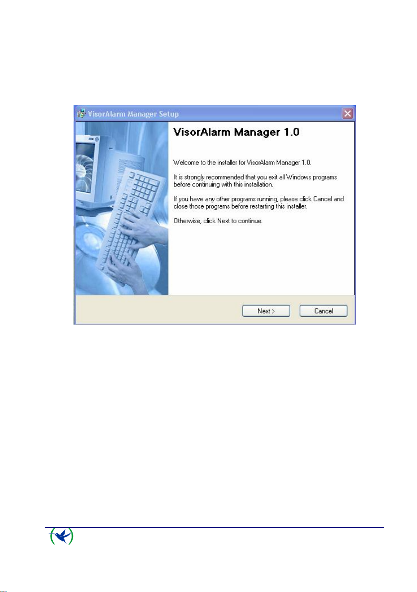
Select the SETUP option to begin the installation. The first screen to appear is the welcome
screen which recommends you close all programs before starting the installation process. This
is to prevent conflicts with files that are in execution when copying files from the installation
CD to the hard disk.
Fig. 2.
Click on the ‘Next’ option to continue installing. The subsequent window permits two modes
of using the application.
• Administrator mode, which permits you to read and modify The VisorALARM
configuration.
• Operator mode, which only allows you to read the device configuration.
VISOR-ALARM Quick Setup Guide
2
Doc. DM381-I
Rev. 1.0
Page 3
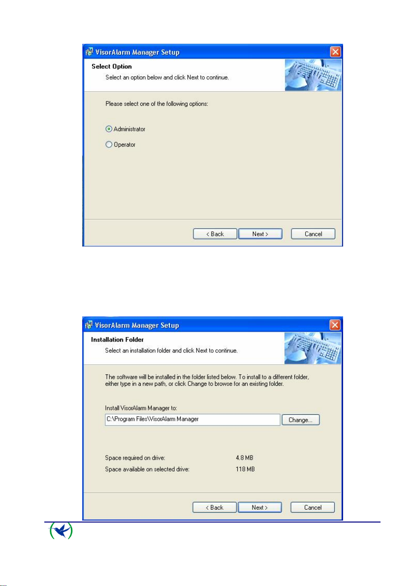
Fig. 3.
Click on ‘Next’ to continue installation. The next screen permits you to select the hard disk
file to install the VisorALARM-Manager application. The installation program shows a
default file. Should you not want to use this, you can select a different file to install the
application using the ‘Change’ button.
VISOR-ALARM Quick Setup Guide
3
Doc. DM381-I
Rev. 1.0
Page 4

Fig. 4.
Press ‘Next’ to continue installation. The subsequent window shows the application shortcut
default name: ‘VisorALARM Manager’.
Fig. 5.
Access the application through the WindowsTM Start up menu: “All programs\VisorALARM
Manager\VisorALARM Manager”.
The next window displays a summary on the previously selected options before carrying out
the actual installation.
VISOR-ALARM Quick Setup Guide
4
Doc. DM381-I
Rev. 1.0
Page 5

Fig. 6.
If you wish to change any of the options, just click on the ‘Back’ button until you find the
window containing the option you wish to change.
The ‘Next’ button initiates the installation process for the files in the selected file.
VISOR-ALARM Quick Setup Guide
5
Doc. DM381-I
Rev. 1.0
Page 6

Fig. 7.
Once the files have been copied, a window appears indicating the installation has been
successfully completed.
Fig. 8.
3. Connection between PC and VisorALARM
Once the VisorALARM-Manager has been correctly installed, you need to check that
connection between the PC and the VISORALARM can be carried out. The steps to execute
are as follows:
3.1. Check that both the VisorALARM and the PC are connected to the same Ethernet.
3.2. Check that the VisorALARM has detected the Ethernet when the Ethernet LAN1
connector LEDs light up. These are located on the rear panel. Likewise, check
that the WindowsTM in the PC indicates the status of the local area network
connection is connected.
3.3. The following step is to configure the PC IP address in order to access the
VisorALARM. There are two situations:
• The VisorALARM is already configured with factory settings. The factory IP
address for the VisorALARM is 192.168.0.200 with mask 255.255.255.0.
Configure the PC network interface with an address pertaining to the
VisorALARM subnet which does not have any other network device, i.e. any
address 192.168.0.X with mask 255.255.255.0, where X is a value between 1
and 254 with the exception of value 200 which is assigned to the
VisorALARM.
The procedure to configure the IP interface in a Windows XPTM is as follows:
1. Access Start\Control Panel\Network Connections.
VISOR-ALARM Quick Setup Guide
6
Doc. DM381-I
Rev. 1.0
Page 7

2. With the right hand mouse button, select Explorer. Select ‘Local
Area Connection’. With the right hand button, select ‘Properties’.
3. The configuration screen that appears is as follows:
Fig. 9.
4. Using the mouse double click on ‘Internet Protocol (TCP/IP)’ and a
window appears where you can enter the IP address, mask and link
port
VISOR-ALARM Quick Setup Guide
7
Doc. DM381-I
Rev. 1.0
Page 8

Fig. 10.
5. To save the configuration changes, select the ‘OK’ button on each of
the windows.
6. The changes are dynamic; consequently you do not need to reboot the
PC.
• The VisorALARM has already been configured. What we need to know is the
VisorALARM IP address and carry out the actions indicated in the previous
point.
3.4. The next step is to check the IP connectivity between the PC and the
VisorALARM. Execute the PING command from the PC to the VisorALARM.
The following window displays the correct operating situation for the PING. This
indicates there is IP connectivity from the PC to the VisorALARM.
VISOR-ALARM Quick Setup Guide
8
Doc. DM381-I
Rev. 1.0
Page 9

Fig. 11.
The following window is shown should the PING command fail. Consequently, it
will be necessary to recheck the IP configuration for both the VisorALARM and
the PC.
Fig. 12.
VISOR-ALARM Quick Setup Guide
9
Doc. DM381-I
Rev. 1.0
 Loading...