

Page 1

SWIFT®
Smart Wireless Integrated Fire Technology
Instruction Manual
Document LS10036-000FL-E Rev: J
4/13/2020 ECN:150692
Page 2

Fire Alarm & Emergency Communication System Limitations
While a life safety system may lower insurance rates, it is not a substitute for life and property insurance!
An automatic fire alarm system—typically made up of smoke
detectors, heat detectors, manual pull stations, audible warning
devices, and a fire alarm control panel (FACP) with remote notification capability—can provide early warning of a d eveloping fire. Such
a system, however, does not assure protection against property
damage or loss of life resulting from a fire.
An emergency communication system—typically made up of an
automatic fire alarm system (as described above) and a life safety
communication system that may include an autonomous control
unit (ACU), local operating console (LOC), voice communication,
and other various interoperable communication methods—can
broadcast a mass notification message. Such a system, however,
does not assure protection against property damage or loss of life
resulting from a fire or life safety event.
The Manufacturer recommends that smoke and/or heat detectors
be located throughout a protected premises following the
recommendations of the current edition of the National Fire
Protection Association Standard 72 (NFPA 72), manufacturer's
recommendations, State and local codes, and the
recommendations contained in the Guide for Proper Use of System
Smoke Detectors, which is made available at no charge to all
installing dealers. This document can be found at http://
www.systemsenso r.com/appguides/. A study by the Federal
Emergency Management Agency (an agency of the United States
government) indicated that smoke detectors may not go off in as
many as 35% of all fires. While fire alarm systems are designed to
provide early warning against fire, they do not guarantee warning o r
protection against fire. A fire alarm system may not provide timely or
adequate warning, or simply may not function, for a variety of
reasons:
Smoke detectors may not sense fire where smoke cannot reach
the detectors such as in chimneys, in or behind walls, on roofs, or
on the other side of closed doors. Smoke detectors also may not
sense a fire on another level or floor of a building. A second-floor
detector, for example, may not sense a first-floor or basement fire.
Particles of combustion or “smoke” from a developing fire may
not reach the sensing chambers of smoke detectors because:
• Barriers such as closed or partially closed doors, walls, chimneys, even wet or humid areas may inhibit particle or smoke
flow.
• Smoke particles may become “cold,” stratify, and not reach the
ceiling or upper walls where de tectors are located.
• Smoke particles may be bl o w n awa y fr om de t ec t ors by ai r ou tlets, such as air conditioning vents.
• Smoke particles may be drawn into air returns before reaching
the detector .
The amount of “smoke” present may be insuf ficient to alarm smoke
detectors. Smoke detectors are designed to alarm at various levels
of smoke density. If such density levels are not created by a developing fire at the location of detectors, the detectors will not go into
alarm.
Smoke detectors, even when working properly, have sensing limitations. Detectors that have photoelectronic sensing chambers tend
to detect smoldering fires better than flaming fires, which have little
visible smoke. Detectors that have ionizing-type sensing chambers
tend to detect fast-flaming fires better than smoldering fires.
Because fires develop in different ways and are often unpredi ctable
in their growth, neither type of detector is necessarily best and a
given type of detector may not provide adequate warning of a fire.
Smoke detectors cannot be expected to provide adequate warning
of fires caused by arson, children playing with matches (especially
in bedrooms), smoking in bed, and violent explosions (caused by
escaping gas, improper storage of flammable materials, etc.).
Heat detectors do not sense particles of combustion and alarm
only when heat on their sensors increases at a predetermined rate
or reaches a predetermined level. Rate-of-rise heat detectors may
be subject to reduced sensitivity over time. For this reason, the rateof-rise feature of each detector should be tested at least once per
year by a qualified fire protection specialist. Heat detectors are
designed to protect property, not life.
IMPORTANT! Smoke detectors must be i nstalled in the same
room as the control panel and in rooms used by the system for the
connection of alarm transmission wiring, communications, signaling, and/or power. If de tectors are not so located, a developing fire
may damage the alarm system, compromising its ability to report a
fire.
Audible warning devices such as bells, horns, strobes, speakers and displays may not alert people if these devices are located
on the other side of closed or partly open doors or are located on
another floor of a building. Any warning device may fail to alert people with a disability or those who have recently consumed drugs,
alcohol, or medication. Please note that:
• An emergency communication system may take priority over a
fire alarm system in the event of a life safety emergency .
• Voice messagi ng systems must be designed to me et intelligibility
requirements as defined by NFPA, local codes, and Authorities
Having Jurisdiction (AHJ).
• Language and instructional requirements must be clearly disseminated on any local displays.
• Strobes can, under certain circumstances, cause seizures in
people with conditions such as epilepsy.
• Studies have shown tha t ce rt ain people, even when they hea r a
fire alarm signal, do not respond to or comprehend the meaning
of the signal. Audib le devices, such as h orns and bell s, can have
different tonal patterns and frequencies. It is the property
owner's responsibility to conduct fire drills and other training
exercises to make people aware of fire alarm signals and
instruct them on the proper reaction to alarm signals.
• In rare instances, the sounding of a warning device can cause
temporary or permanent hearing loss.
A life safety system will not operate without any e lectrical power. If
AC power fails, the system will operate from standby batteries only
for a specified time and only if the batteries have been properly
maintained and replaced regularly.
Equipment used in the system may not be technically compat ible
with the control panel. It is essent ial to use only equi pment li sted for
service with your control panel.
Telephone lines needed to transmit alarm signals from a premises
to a central monitoring station may be out of service or temporarily
disabled. For added protection against telephone line failure,
backu
p radio transmission systems are recommended.
The most common cause of life safety system malfunction is inadequate maintenance. To keep the entire life safety system in excellent working order, ong oing maintenance is required per the
manufacturer's recommendations, and UL and NFPA standards. At
a minimum, the requirements of NFPA 72 shall be followed. Environments with large amounts of dust, dirt, or high air velocity require
more frequent maintenance. A maintenance agre ement should be
arranged through the local manufacturer's representative. Maintenance should be scheduled as required by Nat ional and /or lo cal fire
codes and should be performed by authorized professional life
safety system installers only. Adequate written records of all inspections should be kept.
Limit-D2-2016
2 SWIFT® Smart Wireless Integrated Fire Technology Manual — P/N LS10036-000FL-E:J 4/13/2020
Page 3

Installation Precautions
Adherence to the following will aid in problem-free installation with long-term reliability:
WARNING - Several different sources of power can be connected to the fire alarm control panel. Disconnect all sources of
power before servicing. Control unit and associated equipment may
be damaged by removing and/or inserting cards, modules, or interconnecting cables while the unit is energized. Do not attempt to
install, service, or operate this unit until manuals are read and
understood.
CAUTION - System Re-acceptance Test after Software
Changes: To ensure proper system op eration, this product must be
tested in accordance with NFPA 72 after any programming operation or change in site-specific software. Re-acceptance testing is
required after any change, addition or deletion of system components, or after any modification, repair or adjustment to system
hardware or wiring. All components, circuits, system operations, or
software functions known to be affect ed by a change must be 10 0%
tested. In addition, to ensure that other operations are not inadvertently affected, at least 10% of initi ating devic es that are no t directly
affected by the change, up to a maximum of 50 devices, must also
be tested and proper system operation verified.
This system meets NFPA requirements for operation at 0-49º C/
32-120º F and at a relative humidity 93% ± 2% RH (non-condensing) at 32°C ± 2°C (90°F ± 3°F). However, the useful life of the system's standby batteries and the electronic components may be
adversely affected by extreme temperature ranges and humidity.
Therefore, it is recommended that this system and its peripherals
be installed in an environment with a normal room temperature of
15-27º C/60-80º F.
Verify that wire sizes are adequate for all initiating and indicating
device loops. Most devices cannot tolerate more than a 10% I.R.
drop from the specified device voltage.
Like all solid state electronic devices, this system may operate
erratically or can be damaged when subjected to lightning induced
transients. Although no system is completely immu ne from lightning
transients and interference, proper grounding will reduce susceptibility . Overhead or out side aerial wiring is not recommended, due to
an increased susceptibility to nearby lightning st rikes. Consult with
the Technical Se rvices Department if any problems are anticipated
or encountered.
Disconnect AC power and batteries prior to removing or inserting
circuit boards. Failure to do so can damage circuits.
Remove all electronic assemblies prior to any drilling, filing,
reaming, or punching of the enclosure. When possible, make all
cable entries from the sides or rear. Before making modifications,
verify that they will not interfere with battery, tr ansformer, or printed
circuit board location.
Do not tighten screw terminals more than 9 in-lbs. Over-tightening may damage threads, resulting in reduced terminal contact
pressure and difficulty with screw terminal removal.
This system contains static-sensitive components. Always
ground yourself with a proper wrist strap before handling any circuits so that static charges are removed from the body. Use static
suppressive packaging to protect electronic assemblies removed
from the unit.
Units with a touchscreen display should be cleaned with a dry,
clean, lint free/microfiber cloth. If additio nal cleaning is required,
apply a small amount of Isopropyl alcohol to the cloth and wipe
clean. Do not use detergents, solvents, or water for cleaning. Do
not spray liquid directly ont o th e dis p la y.
Follow the instructions in the installation, operating, and programming manuals. These instructions must be followed to avoid
damage to the control panel and associated equipment. FACP
operation and reliability depend upon proper installation.
Precau-D2-11-2017
FCC Warning
WARNING: This equipment generat es, uses, and can radi-
ate radio frequency energy and if not installed and used in
accordance with the instruction manual may cause interference to radio communications. It has been tested and foun d
to comply with the limits for class A computing devices pursuant to Subpart C of Part 15 of FCC Rules, which is
designed to provide reasonable protection against such
interference when devices are operated in a commercial
environment. Operation of this equipment in a residential
area is likely to cause interference, in which case the user
will be required to correct the interference at his or her own
expense.
Canadian Requirements
This digital apparatus does not exceed the Class A limits for
radiation noise emissions from digital apparatus set out in
the Radio Interference Regulations of the Canadian Department of Communications.
Le present appareil numerique n'emet pas de bruits radioelectriques depassant les limites applicables aux appareils
numeriques de la classe A prescrites dans le Reglement sur
le brouillage radioelectrique edicte par le ministere des
Communications du Canada.
LiteSpeed™ and Lite-Connect™ are trademarks; and Fire-Lite® Alarms, Honeywell®, and SWIFT® are registered trademarks of Honeywell International Inc.
Microsoft® and Windows® are registered trademarks of the Microsoft Corporation. Chrome™ and Google™ are trademarks of Google Inc. Firefox® is a registered
trademark of The Mozilla Foundation.
©2020 by Honeywell International Inc. All rights reserved. Unauthorized use of this document is strictly prohibited.
SWIFT® Smart Wireless Integrated Fire Technology Manual — P/N LS10036-000FL-E:J 4/13/2020 3
Page 4

Software Downloads
In order to supply the latest features and functionality in fire alarm and life safety technology to our customers, we make frequent
upgrades to the embedded software in our products. To ensure that you are installing and programming the latest features, we
strongly recommend that you download the most current version of software for each product prior to commissioning any system.
Contact Technical Support with any questions about software and the appropriate version for a specific application.
Documentation Feedback
Your feedback helps us keep our documentation up-to-date and accurate. If you have any comments or suggestions about our online
Help or printed manuals, you can email us.
Please include the following information:
• Product name and version number (if applicable)
• Printed manual or online Help
• T opic Title (for online Help)
• Page number (for printed manual)
• Brief description of content you think should be improved or corrected
• Your suggestion for how to correct/improve documentation
Send email messages to:
FireSystems.TechPubs@honeywell.com
Please note this email address is for documentation feedback only. If you have any technical issues, please contact Technical
Services.
4 SWIFT® Smart Wireless Integrated Fire Technology Manual — P/N LS10036-000FL-E:J 4/13/2020
Page 5

Table of Contents
Section 1: Overview .......................................................................................................................................................... 9
1.1: Purpose ..............................................................................................................................................................................................................9
1.2: Assumed Knowledge .........................................................................................................................................................................................9
1.3: Additional References........................................................................................................................................................................................9
1.4: About this Manual..............................................................................................................................................................................................9
1.5: About the Mesh Network.................................................................................................................................................................................10
1.6: Abbreviations...................................................................................................................................................................................................10
1.7: Cybersecurity Recommendations ....................................................................................................................................................................10
Section 2: W-GATE Wireless Gateway .......................................................................................................................... 11
2.1: Description.......................................................................................................................................................................................................11
2.2: Agency Approvals............................................................................................................................................................................................11
2.2.1: FCC.......................... ............................. ............................. ............................ .......................................................................................11
2.2.2: Federal Institute of Telecommunications ..................... ............................... .........................................................................................11
2.3: Specifications...................................................................................................................................................................................................11
2.3.1: Environmental Specifications................................... ............................................................................................................................12
2.4: Magnetic Sensors.............................................................................................................................................................................................12
2.4.1: Mesh Formation Magnetic Sensor............................................................................. ...........................................................................12
2.4.2: Magnetic Sensor ......................................................... ..........................................................................................................................12
2.5: LED Indicators.................................................................................................................................................................................................12
2.6: Installing the Gateway .....................................................................................................................................................................................12
2.6.1: Before Installing .............................. .......................................................... .. .........................................................................................12
2.7: Mounting and Wiring.......................................................................................................................................................................................13
2.7.1: Mounting........................................ ............................. ............................. .............................................................................................13
2.7.2: Wiring.... ............................. ............................. ............................. ........................................................................................................14
2.7.3: Gateway Powered by the SLC..............................................................................................................................................................15
2.7.4: Gateway Powered by an External, Regulated +24VDC Source...........................................................................................................15
2.8: Configuration and Programming .....................................................................................................................................................................16
2.8.1: Assign a Profile.....................................................................................................................................................................................16
2.8.2: Remove a Profile ..................................................................................................................................................................................17
Remove a Profile from a Gateway using SWIFT Tools.........................................................................................................................17
Remove a Profile from a Gateway without using SWIFT Tools............................................................................................................18
2.8.3: Create a Mesh Network ....................................... ............................. ....................................................................................................18
2.8.4: SLC Configuration.............. ..................................................................................................................................................................19
2.9: Operations........................................................................................................................................................................................................20
2.9.1: Modes of Operation ............................................... ....................................................... ........................................................................20
Start-up Mode ......................................... ............................. ............................ .......................................................................................20
Factory Default Mode..................................... ............................. ............................. ..............................................................................21
Profile Configured ..................................................................................................................................................................................21
Mesh Formation......................................................................................................................................................................................21
Initial Mesh Restructuring Mode............................................................................................................................................................21
Normal Mode................. ............................. ............................. ............................. .. ................................................................................21
Rescue Mode............................................. ............................. ............................. ....................................................................................21
Mesh Restructuring Mode ......................................................................................................................................................................22
Bootloader Mode ....................................................................................................................................................................................22
Mesh Upgrade.........................................................................................................................................................................................22
Neighboring Network Scan ....................................................................................................................................................................22
2.9.2: LED Patterns. ............................ ............................. ...............................................................................................................................22
2.9.3: Lock/Unlock the Gateway ....................................................................................................................................................................22
Lock/Unlock the Gateway Using SWIFT Tools.....................................................................................................................................22
Password Reset .......................................................................................................................................................................................23
2.9.4: Enable/Disable Max Gateway Trouble Reporting
Completed Wireless Network..................................... .......................................................... ..................................................................23
Possible Wireless Mesh Overlap ................................................................................... .........................................................................23
Disabling Max Gateway Reporting .............................. ............................... ...........................................................................................26
2.9.5: Weak Link Trouble Reporting..............................................................................................................................................................27
Disable Trouble Reporting at the Gateway Using SWIFT Tools...........................................................................................................27
2.9.6: Collapse Network Command............................. ...................................................................................................................................28
Collapse Mesh Network Using SWIFT Tools........................................................................................................................................28
2.9.7: Silence Network Command.... .......................................................... ....................................................................................................29
Silence Mesh Network Using SWIFT Tools ..........................................................................................................................................29
................................................................................................................................23
SWIFT® Smart Wireless Integrated Fire Technology Manual — P/N LS10036-000FL-E:J 4/13/2020 5
Page 6

Table of Contents
2.9.8: Overlapping Wireless Sensor Networks and Limitations........................ ............................... .. ............................................................30
2.9.9: Activation of Wireless Output Devices .............................................. ... ...............................................................................................30
2.9.10: Avoiding RF Interference...................................................................................................................................................................30
Section 3: W-DIS-D Wireless Display Driver................................................................................................................. 31
3.1: Description.......................................................................................................................................................................................................31
3.2: Agency Approvals...........................................................................................................................................................................................32
3.2.1: FCC.......................... ............................. ............................. ............................ .......................................................................................32
3.2.2: Federal Institute of Telecommunications.............................................................................................................................................32
3.3: Specifications...................................................................................................................................................................................................32
3.3.1: Environmental Specifications................................... ............................................................................................................................32
3.4: Magnetic Sensors.............................................................................................................................................................................................33
3.5: Display Driver LED Indicators........................................................................................................................................................................33
3.6: Mounting & Wiring.........................................................................................................................................................................................33
3.6.1: Mounting........................................ ............................. ............................. .............................................................................................33
3.6.2: Wiring.... ............................. ............................. ............................. ........................................................................................................34
3.7: Configuration...................................................................................................................................................................................................35
3.7.1: Assign a Profile.....................................................................................................................................................................................35
3.7.2: Mesh Formation...................... ............................. .................................................................................................................................36
3.7.3: Removing Profiles ................ ............................................................ ....................................................................................................36
Restoring to Factory Default Without Using SWIFT Tools...................................................................................................................36
Restoring to Factory Default Using SWIFT Tools........................... ............................. .........................................................................36
3.8: ANN-80-W Configuration ...............................................................................................................................................................................37
3.9: Display Driver Operations...............................................................................................................................................................................37
3.9.1: Modes of Operation Not in a Mesh Network .......................................................................................................................................38
Bootloader...............................................................................................................................................................................................38
Factory Default .......... ............................. ....................................................... .........................................................................................38
Profile Configured ..................................................................................................................................................................................38
3.9.2: Modes of Operation as a Mesh Participant.......... .................................................................................................................................38
Mesh Formation Mode............................................................................................................................................................................38
Initial Mesh Restructuring Mode............................................................................................................................................................38
Normal Mode................. ............................. ............................. ............................. .. ................................................................................38
Rescue Mode............................................. ............................. ............................. ....................................................................................38
3.9.3: SLC Operation............................................................ ............................. .............................................................................................38
3.9.4: LED Patterns. ............................ ............................. ...............................................................................................................................38
3.10: ANN-80-W Operations..................................................................................................................................................................................38
3.10.1: Annunciator Control Buttons and Visual Indicators ..........................................................................................................................39
3.10.2: Audible Indicators ..............................................................................................................................................................................39
3.10.3: Event Messages ..................................................................................................................................................................................40
RF Comm Loss.......................................................................................................................................................................................40
Trouble Wireless Mesh Formation In Progress......................................................................................................................................40
Low Bat
Trouble Jamming Event...... ....................................................................................................................................................................40
Trouble Duplicate Address.....................................................................................................................................................................40
Trouble Class A Missing 2nd Link.........................................................................................................................................................40
Trouble Wireless Gateway Initializing...................................................................................................................................................40
System Normal .......................................................................................................................................................................................40
Supervisory Tamper................................................................................................................................................................................40
Trouble Weak Link Low Signal Strength...............................................................................................................................................40
Key Bus Trouble................. ............................ .......................................................... ..............................................................................40
Capacity Exceeded ............................. ............................. ............................. ...........................................................................................41
Maximum Gateways...............................................................................................................................................................................41
RF Device No Answer............................................................................................................................................................................41
3.10.4: Clearing messages ..............................................................................................................................................................................41
tery Event....... ............................. ............................. ............................. ....................................................................................40
Section 4: Wireless Devices.......... ... ... ... .... ... ... .............................................................................................................. 42
4.1: Description.......................................................................................................................................................................................................42
4.2: Agency Approvals............................................................................................................................................................................................43
4.2.1: FCC.......................... ............................. ............................. ............................ .......................................................................................43
4.2.2: Federal Institute of Telecommunications ..................... ............................... .........................................................................................43
4.3: Specifications...................................................................................................................................................................................................44
4.4: Installing, Mounting, and Wiring Devices.......................................................................................................................................................44
4.4.1: Batteries..................... ............................. ............................. ............................. ....................................................................................44
6 SWIFT® Smart Wireless Integrated Fire Technology Manual — P/N LS10036-000FL-E:J 4/13/2020
Page 7

Table of Contents
4.5: Configuration and Programming .....................................................................................................................................................................44
4.5.1: Assigning Profiles. ... ............................. ................................................................................................................................................44
4.5.2: Mesh Formation...................... ............................. .................................................................................................................................45
Repeater ..................................................................................................................................................................................................45
4.5.3: Restoring a Device to Factory Default .................................................................................................................................................45
4.6: Device Operations ...........................................................................................................................................................................................47
4.6.1: Modes of Operation ............................................... ...............................................................................................................................47
Factory Default Mode..................................... ............................. ............................. ..............................................................................47
Site Survey Mode....................................................................................................................................................................................47
Profile Assigned Mode ...........................................................................................................................................................................47
Bootloader Mode ....................................................................................................................................................................................47
Mesh Participant Modes .........................................................................................................................................................................47
4.6.2: LED Indicators............. ............................. .......................................................... ..................................................................................48
Section 5: W-SYNC Wireless Synchronization Module ............................................................................................... 49
5.1: Description.......................................................................................................................................................................................................49
5.2: Wiring..............................................................................................................................................................................................................49
5.2.1: FACP .................................... .......................................................... ......................................................................................................49
5.2.2: ECC-50/100 Emergency Command Center .........................................................................................................................................50
5.2.3: HPFF8/HPFF12 NAC Expander ..........................................................................................................................................................51
Section 6: W-USB Adapter.............................................................................................................................................. 52
6.1: Introduction......................................................................................................................................................................................................52
6.2: Agency Approvals...........................................................................................................................................................................................52
6.2.1: FCC.......................... ............................. ............................. ............................ .......................................................................................52
6.2.2: Federal Institute of Telecommunications ..................... ............................... .........................................................................................52
6.3: Specifications...................................................................................................................................................................................................53
6.3.1: Electrical Specifications ................ ............................. ............................. .............................................................................................53
6.3.2: Serial Communication Specification ....................................................................................................................................................53
6.3.3: Mechanical Specifications................................................. ...................................................................................................................53
6.3.4: Environmental Specifications................................... ............................................................................................................................53
6.4: Driver Installation............................................................................................................................................................................................53
Appendix A: SWIFT Tools............................................................................................................................................... 57
A.1: Description......................................................................................................................................................................................................57
A.2: Launching SWIFT Tools.................................................................................................................................................................................57
A.2.1: Creating a New Jobsite ........................................................................................................................................................................57
A.2.2: Opening an Existing Jobsite ................................................................................................................................................................58
A.3: Connecting to the Gateway.............................................................................................................................................................................58
A.3.1: Accessing a Locked Gateway .................... ............................. ............................. ................................................................................58
A.3.2: Creating a New Password for a Gateway ............................................................................................................................................58
Appendix B: Site Survey................................................................................................................................................. 60
B.1: Conduct a Site Survey.....................................................................................................................................................................................60
B.1.1: Link Quality Test ........ ............................. ............................. ............................. ..................................................................................60
Basic Requirements of a Link Quality Test........... .......................................................... .......................................................................60
Conduct a Link Quality Test.............................. .......................................................... ...........................................................................60
Results of a Link Quality Test ................................................. ............................. ..................................................................................61
After a Link Quality Test........................................................................................................................................................................61
B.1.2: RF Scan Test .................... ............................ ........................................................ ................................................................................61
Conduct an RF Scan Test............... ............................. .......................................................... ..................................................................61
Status of an RF Scan Test... ............................ ............................. ............................. ..............................................................................61
B.1.3: Retrieving Site Survey Results .............. .......................................................... ....................................................................................62
Appendix C: Troubleshooting and Testing................................................................................................................... 63
C.1: Troubleshooting ..............................................................................................................................................................................................63
C.2: Testing the Gateway and Devices ...................................................................................................................................................................64
C.2.1: Testing LED Indicators........................................................................................................................................................................64
C.3: Testing the Wireless Network .........................................................................................................................................................................64
C.3.1: Network Topology................................................ ... ............................. ...............................................................................................65
Parent-Child Devices .............. ............................. ........................................................ ...........................................................................65
Orphan Devices................ ............................. .......................................................... ................................................................................65
Class A Compliance........................................ ............................. ............................. ..............................................................................65
C.3.2: History Events.................... .......................................................... ........................................................................................................65
SWIFT® Smart Wireless Integrated Fire Technology Manual — P/N LS10036-000FL-E:J 4/13/2020 7
Page 8

Table of Contents
C.3.3: Network Snapshots ..................... ............................. .. ............................. .............................................................................................65
C.3.4: Network Statistics ....... ............................. .......................................................... ..................................................................................65
C.3.5: Device Attributes .......................... ............................. ..........................................................................................................................65
Appendix D: LED Indicators........................................................................................................................................... 67
Appendix E: Firmware Upgrade/Downgrade Instructions........................................................................................... 74
E.1: W-USB Adapter Upgrade Procedure...............................................................................................................................................................74
E.2: Mesh Network Firmware Upgrade/Downgrade Procedure.............................................................................................................................75
E.3: Device, Gateway, and Display Driver Firmware Upgrade/Downgrade Procedure.........................................................................................75
E.4: Distributed Firmware Updates ........................................................................................................................................................................76
Index................................................................................................................................................................................. 77
8 SWIFT® Smart Wireless Integrated Fire Technology Manual — P/N LS10036-000FL-E:J 4/13/2020
Page 9

1.1 Purpose
The SWIFT® Network Manual provides an overview of the following:
• Wireless fire alarm system
• Instructions for installing and configuring the wireless devices
• Information on monitoring the status of the wireless devices
• Removal and replacement procedures of the Wireless Gateway and Display Driver
• Testing, maintenance, and firmware upgrade information of the Wireless Gateway and Display Driver
1.2 Assumed Knowledge
This document is created with the assumption that all use rs are familiar with working on a PC and laptop for configuration purposes.
Installers should be familiar with the fire alarm and related service standards. The terminology and level of details of this document
reflect this assumption.
1.3 Additional References
The table below provides a list of documents referenced in this manual, as well as documents for selected other compatible devices.
Fire•Lite SLC Wiring Manual 51309
ES-50X Series Fire Alarm Control Panel LS10129-000FL-E
ES-200X Series Fire Alarm Control Panel LS10131-000FL-E
MS-9200UDLS Fire Alarm Control Panel 52750
MS-9600(UD)LS Fire Alarm Control Panel 52646
ANN-80 Series Remote Fire Annunciator 52749
W-SD355 Wireless LiteSpeed Photo Detector with 4” Base I56-4081
W-SD355T Wireless LiteSpeed Photo/Heat Detector with 4” Base I56-4081
W-H355R Wireless LiteSpeed Rate Of Rise Heat Sensor with 4” Base I56-4082
W-H355 Wireless LiteSpeed Fixed Heat Sensor with 4” Base I56-4082
W-MMF Wireless Monitor Module I56-4083
W-CRF Wireless Relay Module I56-8503
W-BG12LX Wireless Pullstation I56-426X
WAV-RL Red Wall AV Base I56-6517
WAV-WL White Wall AV Base I56-6517
WAV-CRL Red Ceiling AV Base I56-6517
WAV-CWL White Ceiling AV Base I56-6517
SWIFT Wireless AV Bases I56-6517
W-SYNC Wireless Sync Module I56-6518
MDL3 Sync Module I56-3157
HPFF8 NAC Expander 53499
HPFF12 NAC Expander 53576
Section 1: Overview
1.4 About this Manual
This manual correlates with SWIFT Tools version 4.0 (and higher) an d the programming features included in that release. Devices not
running the current version of the software will not have the same capabilities. Ensure the latest version of SWIFT Tools is installed for
proper functionality.
Systems running version 4.0 (and higher) will:
• require device tamper to remove a profile (return to factory default) with a 60 minute timeout.
• have option to enable/disable max gateway trouble reporting.
• require device tamper to upgrade the firmware on individual devices.
Systems running 4.0 (and higher) will not be able to:
• create profiles in the gateway without using SWIFT Tools.
• distribute profiles from the gateway to devices.
• use devices as profile distributors.
SWIFT® Smart Wireless Integrated Fire Technology Manual — P/N LS10036-000FL-E:J 4/13/2020 9
Page 10

Overview About the Mesh Network
1.5 About the Mesh Network
All devices within the mesh network must be running the same firmware version. Refer to Appendix E, “Firmware Upgrade/Downgrade
Instructions” for more information.
Use of these products in combination with non-Honeywell products in a wireless mesh network, or to access, monitor, or control devices
in a wireless mesh network via the internet or another external wide area network, may require a separate license from Sipco, LLC. For
more information, contact Sipco, LLC or IntusIQ (Ipco), LLC at 8215 Roswell Rd, Building 900, Suite 950. Atlanta, GA 30350, or at
www.sipcollc.com or www.intusiq.com.
1.6 Abbreviations
The following table lists the abbreviations and their definitions used in this manual.C
Abbreviation Definition
AHJ Authority Having Jurisdiction
ANSI American National Standards Institute
dBm Units of RF power (0dBm = 1mW)
FACP Fire Alarm Control Panel
FCC Federal Communications Commission
ISM Band Industrial, Scientific and Medical Radio Bands
LCD Liquid Crystal Display
LED Light Emitting Diode
mA Milliampere
MHz Megahertz
NFPA National Fire Protection Association
PC Personal Computer
RF Radio Frequency
SLC Signaling Line Circuit
UI User Interface
UL Underwriters Laboratories
W-DIS-D Wireless Display Driver
W-GATE Wireless Gateway
1.7 Cybersecurity Recommendations
• When using SWIFT Tools to update the firmware of the gateway or devices, ensure updates are performed in a secure location
where no eavesdropping on the wireless signals is possible.
• Ensure the PC running SWIFT Tools has full disk encryption. Full encryption of any backed-up data is also recommended.
• The wireless gateway should be secured in a location which is only accessible to authorized personnel.
• When any SWIFT gateway or device is decommissioned from service, return the equipment to the factory default state by removing
profiles.
10 SWIFT® Smart Wireless Integrated Fire Technology Manual — P/N LS10036-000FL-E:J 4/13/2020
Page 11
2.1 Description
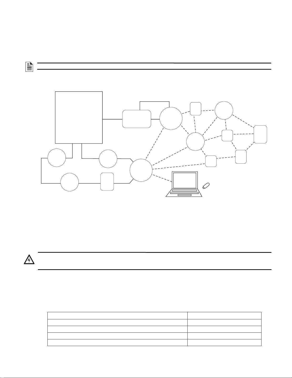
Figure 2.1 SWIFT Network
FACP
ANN-80-W
SLC
wired SLC devices
W-GATE
Gateway
SWIFT ANN Bus
ANN Bus
Driver
(W-DIS-D)
wireless mesh
network
SWIFT
Tools
W-USB
24VDC
Supply
!
The W-GATE is a device in a wireless fire system that acts as a bridge b etwe en fire ala rm control panels (FACPs) and wireless fire
devices. All wireless fire devices communicate with the gateway over the wireless network formed by the devices and the gateway.
The SWIFT Wireless Sensor Network includes a W-DIS-D (Wireless Display Driver). The W-DIS-D and an ANN-80-W are required for
the display of wireless-specific events. The W-DIS-D and ANN-80-W are explained in detail in Section 3.
NOTE: The W-DIS-D and ANN-80-W are not required for use with the ES-50X or ES-200X FACPs.
The gateway is powered by either the SLC loop or by any external +24VDC UL listed power supply. The gateway uses the LiteSpeed
protocol on the SLC to communicate with the panel and a proprietary wireless protocol to communicate with wireless fire devices. The
following graphic is an illustration of the components of the SWIFT Network.
Section 2: W-GATE Wireless Gateway
2.2 Agency Approvals
2.2.1 FCC
This device complies with part 15 of the FCC Rules. Operation is subject to the following two conditions:
1. This device may not cause harmful interference, and
2. This device must accept any interference received, including interference that may cause undesired operation.
3. FCC ID: PV3WFSGW
WARNING: DO NOT MAKE CHANGES TO THE EQUIPMENT
CHANGES OR MODIFICA TIONS NOT EXPRESSLY A PPROVED BY THE MANUFACTURER COULD VOID THE USER’S
AUTHORITY TO OPERATE THE EQUIPMENT.
2.2.2 Federal Institute of Telecommunications
This device utilizes the Honeywell915 rev A radio module and complies with IFETEL standard(s).
IFT: RCPHOSW14-1983
2.3 Specifications
Following are the specifications of the wireless gateway.
External Supply Electrical Ratings 18V-30V
SLC Electrical Ratings 15V-30V
Maximum current when using the external supply 40mA
Maximum current when using the SLC power supply 24mA
Specifications Data
SWIFT® Smart Wireless Integrated Fire Technology Manual — P/N LS10036-000FL-E:J 4/13/2020 11
Page 12
W-GATE Wireless Gateway Magnetic Sensors
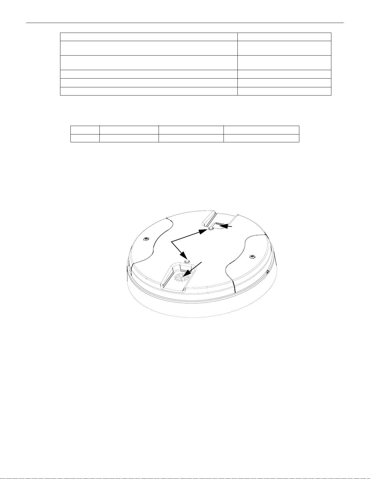
Figure 2.2 LEDs and Mesh Formation Sensor on the W-GATE
LEDs
Mesh
Formation
Magnetic
Sensor
cover.wmf
magnetic
sensor
Maximum SLC Resistance 50Ω
Minimum signal strength level needed at the receiver for a primary path with weak
link trouble reporting enabled.
Minimum signal strength level needed at the receiver for a secondary path or
primary path with weak link trouble reporting disabled.
Maximum ambient noise level -85dBm
Maximum RF Power Output +17dBm (Tx power level without antenna)
Radio Frequency Lower ISM Band (902 - 928MHz).
1 Ensure that the primary path signal strength level is within recommended guidelines to assure proper communication in the
mesh network.
-55dBm
Must be 18 dBm higher than the noise
floor down to a minimum of -80dBm
1
1
2.3.1 Environmental Specifications
System Operating Temperature Storage Temperature Humidity
Gateway 0°C-49°C / 32°F-120°F -10°C- 60°C / 14°F-140°F 10 to 93% RH, Non-condensing
2.4 Magnetic Sensors
Magnets must have a holding strength of 10 lbs or greater. Use either the north or south pole of the magnet to activate sensors.
2.4.1 Mesh Formation Magnetic Sensor
The mesh formation magnetic sensor (refer to Figure 2.2) transitions the gateway in and out of mesh formation mode. The initial activation of the sensor puts the gateway in mesh formation mode (as long as it contains a profile). A subsequent activation of the magnetic
sensor transitions the gateway out of mesh formation and into the initial mesh restructuring and normal mode. The gateway can be
placed back into mesh formation mode by activating the magnet sensor once again. The LED next to the profile magnet sensor turns on
green for ½ a second when the sensor is activated..
2.4.2 Magnetic Sensor
The square magnetic sensor can be used to start a communication session with SWIFT Tools. See Section A.3 on page 58 for more information.
2.5 LED Indicators
The two LEDs on the gateway blink in the same pattern to allow the LED to be viewed from any angle. LED patterns are explained in
Appendix D.
2.6 Installing the Gateway
2.6.1 Before Installing
Choose a location for the gateway that is clean, dry , and vibration-free. The area should be readily accessible with suf ficient room to easily install and maintain the gateway. Metal obstructions impede the radio frequency communication and should be avoided. Carefully
unpack the system and inspect for shipping damage if any. All wiring must comply with the national and local codes for fire alarm systems.
12 SWIFT® Smart Wireless Integrated Fire Technology Manual — P/N LS10036-000FL-E:J 4/13/2020
Page 13
Mounting and Wiring W-GATE Wireless Gateway
!
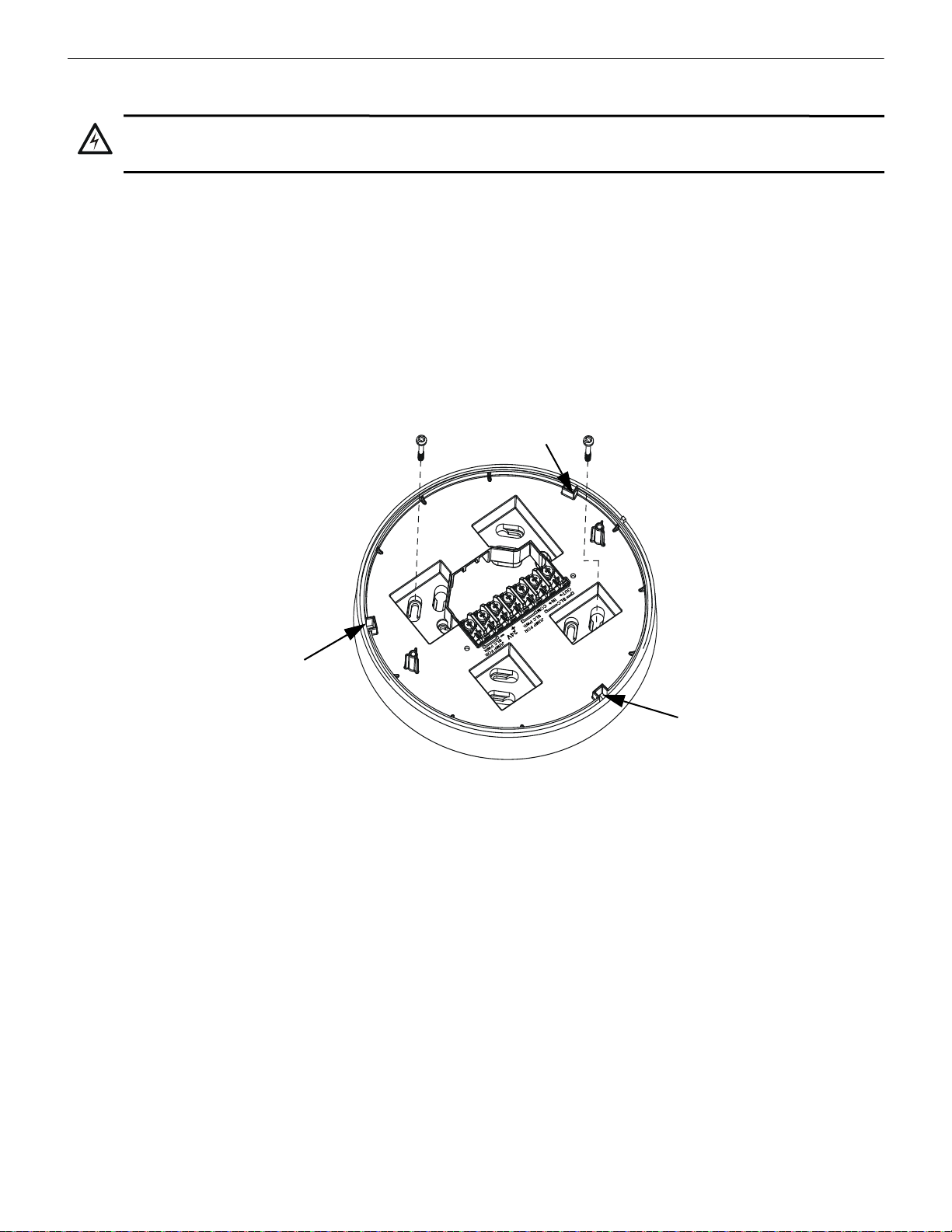
Figure 2.3 Mounting Plate for Wireless Gateway
2.2.wmf
locating pin
locating pin
locating pin
2.7 Mounting and Wiring
WARNING: POLYPROPYLENE ELECTRICAL INSULATION MATERIAL
ENSURE THAT THE POLYPROPYLENE ELECTRICAL INSULATION MATERIAL COVERING THE PRINTED CIRCUIT
BOARD INSIDE THE GATEWAY IS NOT REMOVED OR TAMPERED WHILE INSTALLING OR CLEANING.
2.7.1 Mounting
The gateway has two major pieces, the cover and the mounting plate. The mou nting pla te is mounte d to the wall or c eiling, and f ield wi ring is connected to it. The cover contains the printed circuit board and is fastened to the mounting plate once the wiring is completed.
Mount the mounting plate directly to an electrical box on the ceiling or wall. The plate mounts directly to a 4˝ square (with and without
plaster ring), 4˝ octagon, 3 1/2˝octagon, single gang or double gang junction boxes. If an electrical box is not available, the mounting
plate can be mounted to any flat surface and the wiring can be connected via the knockout points in the mounting plate.
To mount the gateway:
1. Pull the wiring through the opening in the mounting plate.
2. Mount the mounting plate to the junction box or ceiling. See Figure 2.3 below.
3. Connect field wiring to the terminals, as described in Section 2.7.2.
4. Connect necessary jumpers where applicable, as described in Section 2.7.3.
5. To mount the cover, align the locating pins on the cover to the corresponding slots in the mounting plate. See Figure 2.4.
6. Secure the cover by tightening the mounting screws.
SWIFT® Smart Wireless Integrated Fire Technology Manual — P/N LS10036-000FL-E:J 4/13/2020 13
Page 14
W-GATE Wireless Gateway Mounting and Wiring
Figure 2.4 Attaching Cover to Mounting Plate
2.3.wmf
locating pin
locating pin
locating pin
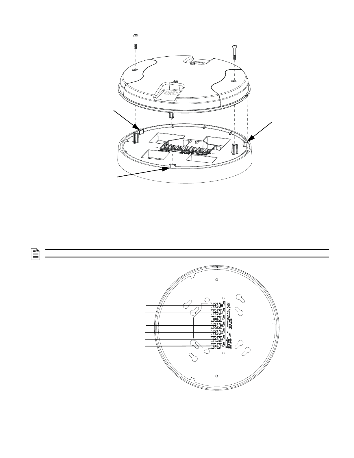
Figure 2.5 W-GATE Mounting Plate - Terminal Layout
A7 - SLC Out+/In+
A6 - SLC In+/Out +
A5 - SLC- (Common)
A4 - SLC Power Select 2
A3 - Power +24VDC
A2 - Power Ground
A1 - SLC Power Select 1
2.4.wmf
2.7.2 Wiring
• All wiring must be installed in compliance with the National Electrical Code and the local codes having jurisdiction.
• 12-18 AWG is recommended.
For wiring connections:
1. Strip about 3/8” of insulation from the end of the wire.
2. Slide the stripped end of the wire under the appropriate terminal and tighten the screw.
NOTE: Do not loop the wire under the screw terminals.
14 SWIFT® Smart Wireless Integrated Fire Technology Manual — P/N LS10036-000FL-E:J 4/13/2020
Page 15
Mounting and Wiring W-GATE Wireless Gateway
+
+
-
-
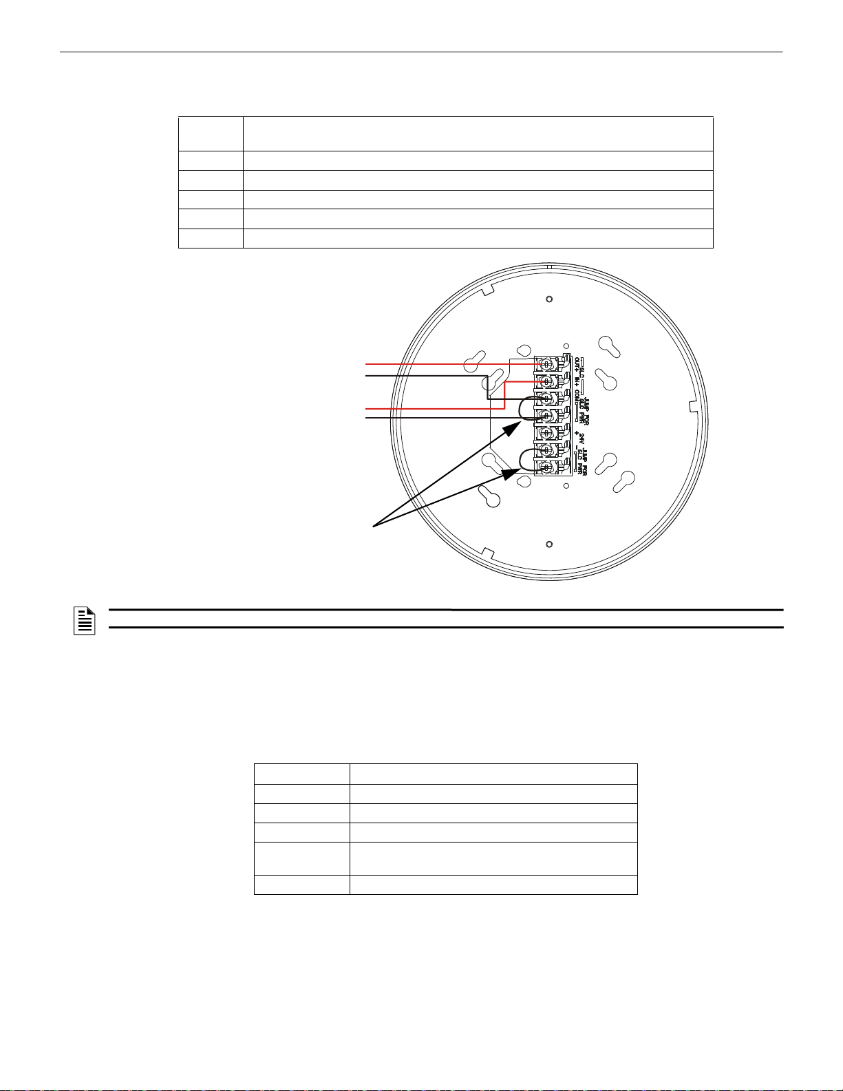
Figure 2.6 Wiring Connections: W-GATE Powered by the SLC
SLC out to next device (Class B)
or SLC return to FACP (Class A)
SLC in from FACP/device
jumpers
2.5.wmf
2.7.3 Gateway Powered by the SLC
To power the gateway using the signaling line circuit, connect the gateway as described in the table and graphic below:
Terminal
Pins
A5 and A7 SLC - (Common) & SLC Output +
A5 and A6 SLC - (Common) & SLC Input +
A4 and A5 Jumper selection to enable power from the SLC supply. (Insert Jumper when using SLC power.)
A3 Unused
A1 and A2 Jumper selection to enable power from the SLC supply. (Insert Jumper when using SLC power.)
Description
NOTE: Use of the same wire gauge is recommended if there are multiple connections to the same terminal.
The gateway provides isolation of short circuits on the SLC in Class A (Style 6) installations. SLC connections are power-limited by the
panel. An interruption in the SLC that causes a loss of power at the gateway for more than 100ms may result in a trouble condition and
loss of fire protection provided by the wireless devices for approximately 15 minutes. Use of an external +24V power source (not SLC
power) is recommended for installations that require fire protection in the presence of short circuits, including Class A applications and
applications that use isolator modules. Refer to the SLC Wiring Manual for more information on wiring using isolators.
2.7.4 Gateway Powered by an External, Regulated +24VDC Source
To power the gateway using an exter nal, regulated +24VDC source, connect the gateway as described in the table and drawing below.
Terminal Pins Devices Powered
A5 & A7 SLC Output
A5 & A6 SLC Input
A4 Unused
A2 & A3 +24VDC input. Voltage range from +18VDC to +30VDC.
Use only power-limited device circuits.
A1 Unused
SWIFT® Smart Wireless Integrated Fire Technology Manual — P/N LS10036-000FL-E:J 4/13/2020 15
Page 16
W-GATE Wireless Gateway Configuration and Programming
+
+
-
-
+
-
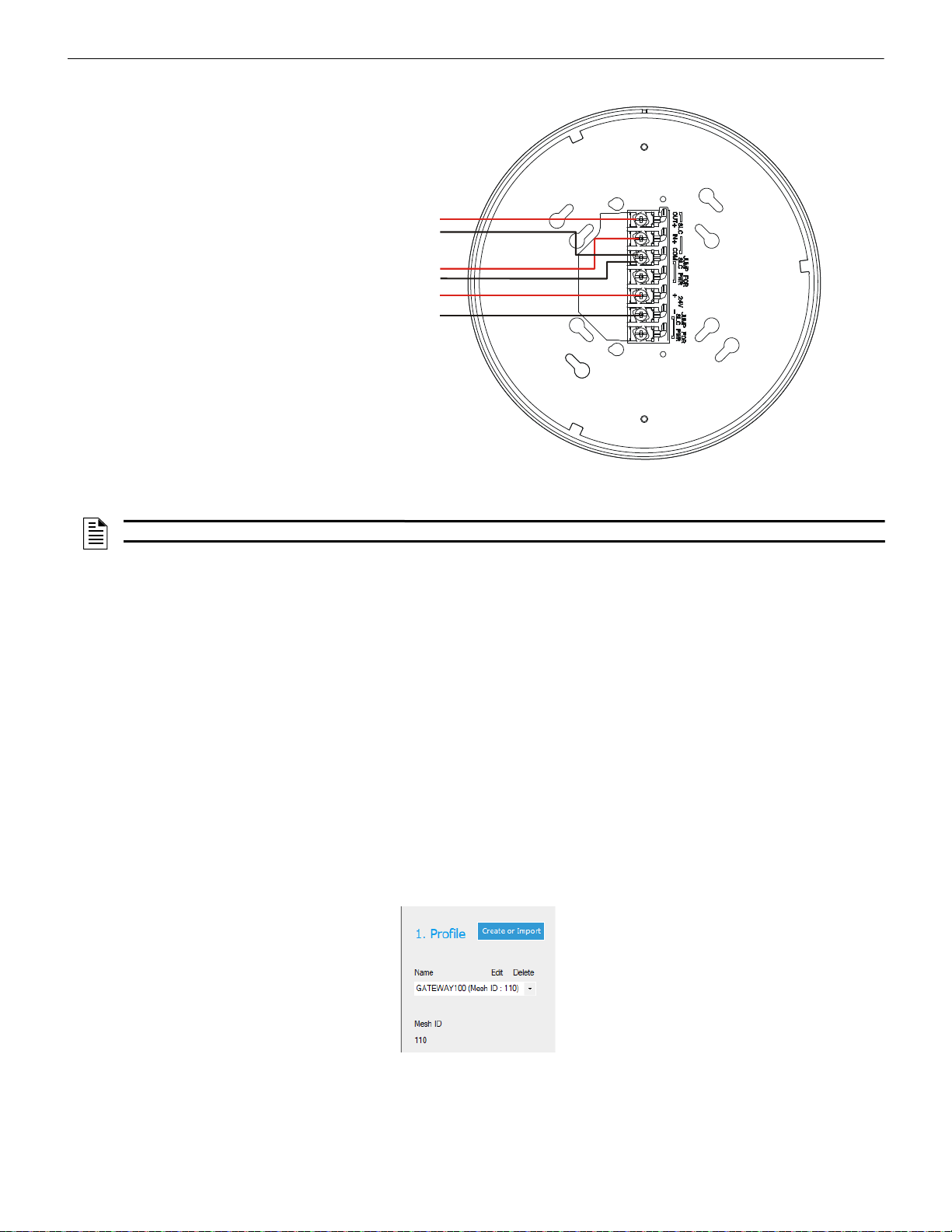
Figure 2.7 Wiring Connections: W-GATE Powered by an External , Regu la te d +2 4 VDC Sou rc e
SLC in from FACP/device
External +24VDC Power
SLC out to next device (Class B)
or SLC return to FACP (Class A)
2.6.wmf
Figure 2.8 Selecting a Profile
assignprofile_select.jpg
NOTE: It is recommended to use the same wire gauge if there are multiple connections to the same terminal.
The gateway provides isolation of short circuits of the SLC in Class A (Style 6) installations. SLC connections are power-limited by the
panel. +24VDC must be power-limited by the source.
2.8 Configuration and Programming
To successfully configure and/or program the gateway:
1. Create a profile. A profile binds a gateway and the devices in a mesh network together. The profile will contain a mesh ID that is
used when forming the associations. All devices, including the gateway, require a common profile.
2. Assign a profile using SWIFT Tools. Assign the profile to every device that will be a part of the mesh. This will enable all the
devices that have that profile to form associative links when the mesh is formed .
3. Form the mesh. The mesh cannot be formed until the profile is assigned to the gateway and to its devices.
Perform the follow steps using SWIFT Tools.
2.8.1 Assign a Profile
To assign a profile to the gateway using SWIFT Tools:
1. Connect the W -USB device to your lap top. For more information on the W-USB adapter, refer to Section 6, “W-USB Ad apter”, on
page 52.
2. Launch SWIFT Tools. Refer to Appendix A for more information.
3. From the Home Screen, select the Create Mesh Network function.
4. Create a new profile or Import an existing profile as required.
5. Select and open the profile to be assigned to the gateway from the Name drop-down box in the Profile section.
16 SWIFT® Smart Wireless Integrated Fire Technology Manual — P/N LS10036-000FL-E:J 4/13/2020
6. Power on the gateway within approximately 20 feet of the laptop running SWIFT Tools.
7. Place the devices with batteries installed within 20 feet of the laptop, with a minimum of 3 feet between each device. If the devices
were inadvertently installed in the building prior to assigning them profiles, either remove them to bring them near the laptop or
bring the laptop near each of the installed devices in order to assign them the profile.
Page 17
Configuration and Programming W-GATE Wireless Gateway
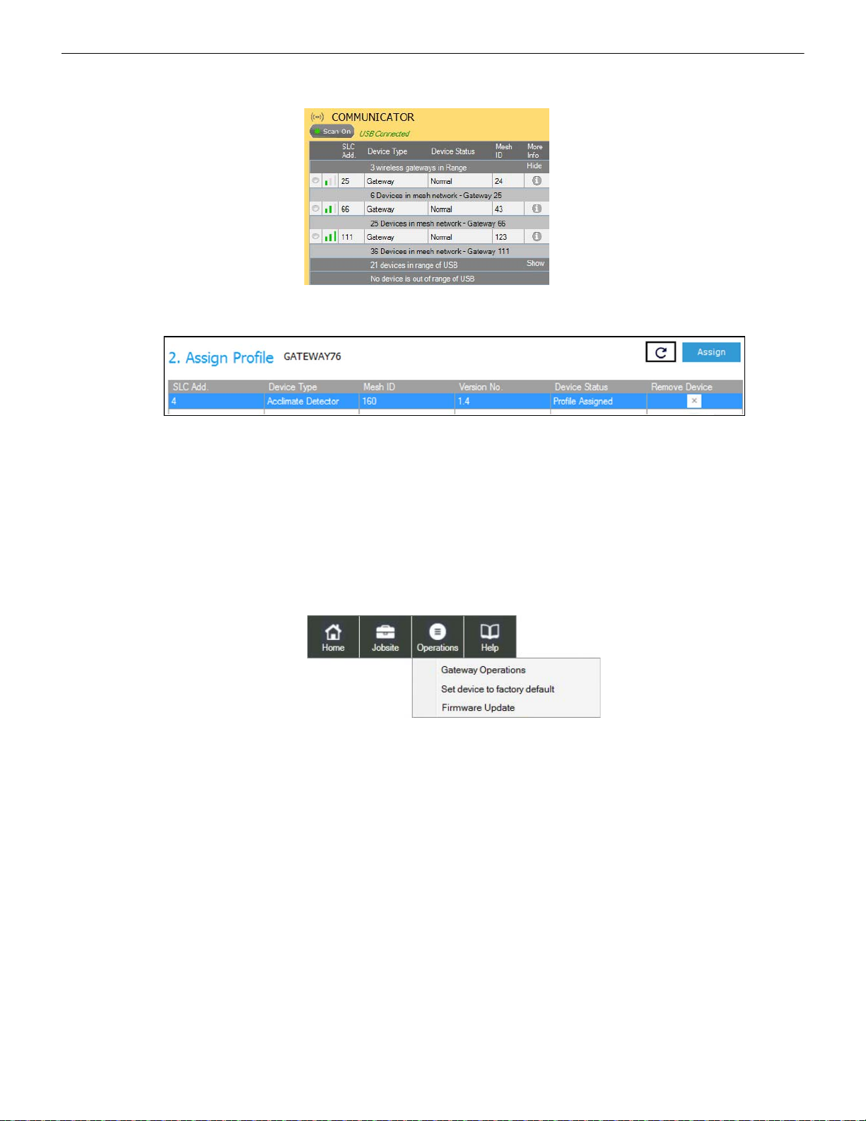
Figure 2.9 Gateway Selection
communicator_show_4,jpg
Figure 2.10 Assign a Profile
assignprofile_confirm2.jpg
Figure 2.11 Operations Menu
operations.jpg
8. Ensure that the Scan On selection box in the Communicator W indow is checked.
9. Select the gateway from the Communicator Window on the right side of the Tools screen.
10. Click Assign.
The gateway is now included in the list of devices with a profile assigned. The LEDs on the gateway will turn on green for 10 seconds
after the profile has been received.
2.8.2 Remove a Profile
Remove a Profile from a Gateway using SWIFT Tools
1. Connect the W-USB adapter to your laptop. For more information on the W-USB device, refer to Section 6, “W-USB Adapter”, on
page 52.
2. Launch SWIFT Tools. Refer to Appendix A, “SWIFT Tools” for more information on launching the SWIFT Tools application.
3. From the Home Screen, select the Site Sur v ey , Create Mesh Network, or Diagnostics function.
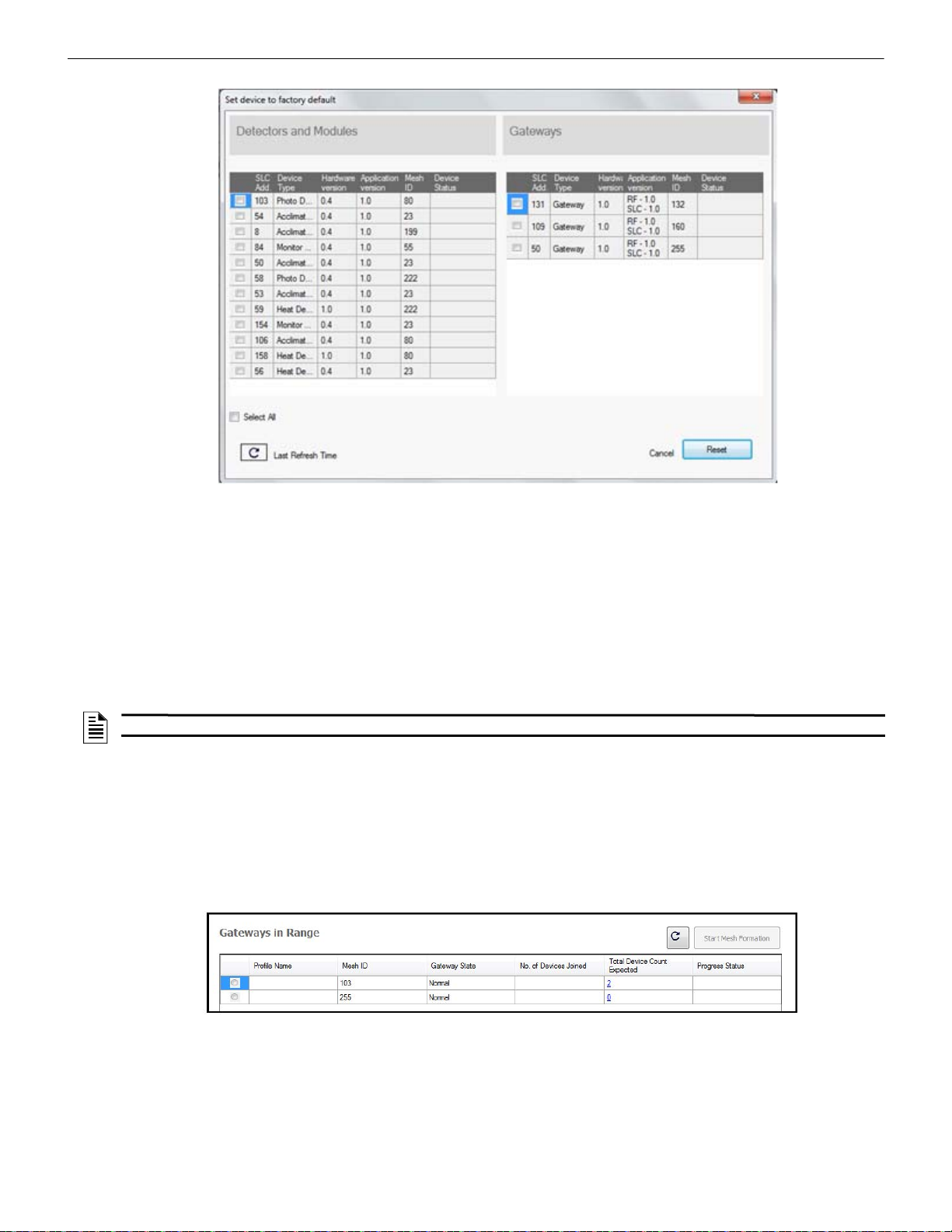
4. Click Operations and select Set device to factory default.
5. The Reset Devices screen appears, displaying the gateway and other devices that have a profile assigned. Click to select the
gateway and click Reset to remove the profile.
SWIFT® Smart Wireless Integrated Fire Technology Manual — P/N LS10036-000FL-E:J 4/13/2020 17
Page 18
W-GATE Wireless Gateway Configuration and Programming
resetdevices.jpg
Figure 2.12 Reset Devices Screen
meshoptools.png
Figure 2.13 Gateways in Range Table
The profile is removed and the gateway is reset to factory default state. Refer to Section 4.5.3 on page 45 for information on returning
devices to the factory default state.
Remove a Profile from a Gateway without using SWIFT Tools
1. Start with the gateway powered off. The process is performed during start-up.
2. Power on the gateway using SLC power or external +24V. Refer to Sections 2.7.3 and 2.7.4 for more information.
3. Verify the gateway is in the profile modification state. The gateway is in the profile modification state when both the LEDs on the
gateway double blink yellow every second for ten seconds.
4. Activate both magnetic sensors on the gateway within ten seconds of start-up while the double yellow blink is active. If the ten
second window is missed, power down the gateway and repeat the process starting at step 1.
The LEDs on the gateway will blink green every second for five seconds indicating that the profile is removed.
NOTE: If a gateway has been locked using SWIFT Tools, the ability to remove a profile using magnets is no longer available.
2.8.3 Create a Mesh Network
To create a mesh network using the SWIFT Tools, perform the following steps.
1. Connect the W -USB device to your lap top. For more information on the W-USB adapter, refer to Section 6, “W-USB Ad apter”, on
page 52.
2. Launch SWIFT Tools. Refer to Appendix A for more information.
3. From the Home Screen, select the Create Mesh Network function.
4. Proceed to the second step of the Create Mesh Networ k function by clicking the arrow marked Next at the bottom of the screen.
5. Click to select the desired gateway displayed in the Gateways in Range table.
6. The Enter password for Gateway screen is displayed. Enter the password and follow the on-screen instructions. Note that, once
accessed, the login will be valid for only 30 minutes. For additional information, refer to “Lock/Unlock the Gateway” on page 22.
7. Click Start Mesh Formation.
8. A message is displa yed. C lic k Yes to proceed or click No to cancel.
9. The Mesh Formation screen is displayed indicating that the mesh formation is in progress.
18 SWIFT® Smart Wireless Integrated Fire Technology Manual — P/N LS10036-000FL-E:J 4/13/2020
Page 19
Configuration and Programming W-GATE Wireless Gateway
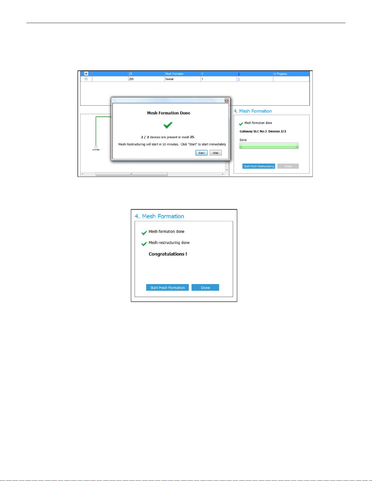
Figure 2.14 Completed Mesh Formation Screen
startmeshformation5.jpg
Figure 2.15 Completed Restructuring Screen
meshrestruct_end.jpg
• The Progress Status column indicates progress status of the selected gateway.
• The No. of Devices Joined column indicates the number of devices that are in the mesh network including the gateway.
• The Total Device Count Expected column indicates the number of devices expected to join including the gateway. This field is
editable. Click in to the field to edit the number of device count expected.
10. Once the expected count of devices have joined the mesh, a message is disp laye d to show that the Mesh formation is complete and
an option is given to choose to start mesh restructuring immediately or wait for any other devices to join.
11. Start Mesh Restructuring (by either waiting or clicking Start). Once Restructuring is initiated, the progress displays. When Mesh
Restructuring is complete, the following success message is shown. For further operating instructions, refer to Section 2.9,
“Operations”.
2.8.4 SLC Configuration
The gateway:
communicates with the control panel via the SLC.
is a LiteSpeed-only device.
does not support CLIP mode.
requires the use of an ANN-80-W for event details because FACPs have limited support for displaying all troubles from the
wireless device. Refer to the appropriate section below for configuration steps. (This does not apply to the ES-50X or ES-200X
Series panels.)
is only compatible with Gateway firmware version 2.1 or higher.
SWIFT® Smart Wireless Integrated Fire Technology Manual — P/N LS10036-000FL-E:J 4/13/2020 19
Page 20
W-GATE Wireless Gateway Operations
TENS
8
9
10
11
12
13
14
15
0
1
2
3
4
5
6
7
ONES
8
9
0
1
2
3
4
5
6
7
Figure 2.16 Address Rotary Switches
SLC-setaddtph.wmf
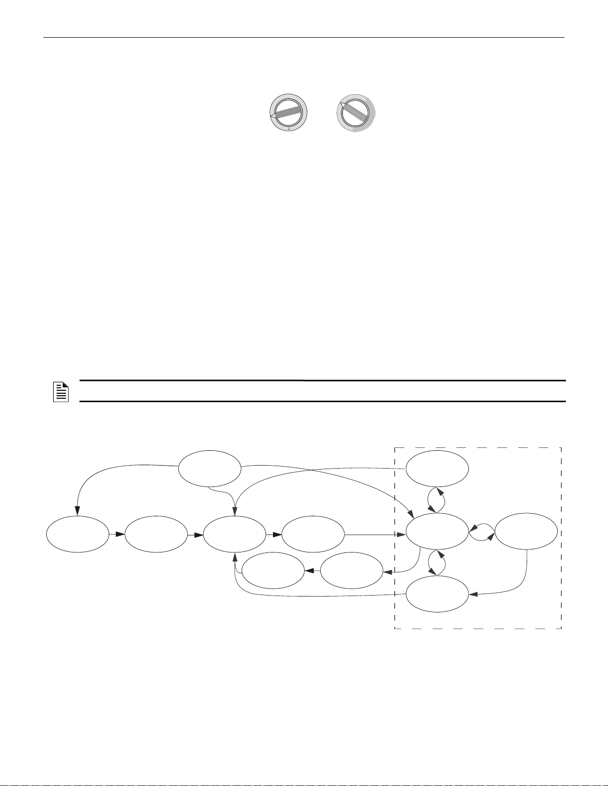
Figure 2.17 Gateway Modes Of Operation
Start-up
Factory
Default
Profile
Configured
Mesh
Formation
Initial Mesh
Restructuring
Normal Mode
Mesh
Restructuring
Rescue Mode
Fire Protection Provided
Neighboring
Network Scan
Mesh
Upgrade in
Progress
Mesh
Upgrade
Preparation
The gateway requires three consecutive SLC addresses for all FACPs except the ES Series, which requires only the one base address. Set
the base address using the rotary dials on the gateway prior to installa tion. Ensure the address and the next two addresses on the SLC
loop are available.
The base address uses the following configuration parameters:
• Module Type: Monitor Module
• Type Code Label: Wireless Gateway (for ES Series panels: Wireless = True)
The gateway does not cause any alarms at this address, but the SLC point is used for supervision of the gateway.
The base address +1 (not required with ES Series panels) uses the following configuration parameters:
• Module Type: Monitor Module
• Type Code Label:
Tamper
This address is a latching supervisory condition that goes active whenever a wireless detector in the mesh is removed from its base or a
module has its cover plate removed (tamper). This SLC point does not show the address of the tampered device. The ANN-80-W displays the device address information. The latching condition is cleared with a reset on the ANN-80-W.
The base address +2 (not required with ES Series panels) uses the following configuration parameters:
• Module Type: Monitor Module
• Type Code Label:
Trouble
This address is a latching or non-latching trouble condition, depending on the trouble event, that goes active whenever a wireless device
in the mesh is in a trouble condition. Refer to Section 3.10.3, “Event Messages”, on page 40 for the message displayed at the ANN-80-W
for the trouble event. Latching troubles are cleared with a reset on the ANN-80-W.
The specific address and trouble condition is displayed on the ANN-80-W.
NOTE: When a wireless relay, wireless AV base, or wireless sync module is in use, module device count must be limited to 99 modules
per loop. This includes wired and wireless modules that are on the same loop. The module address range must be within 1-99.
2.9 Operations
2.9.1 Modes of Operation
Start-up Mode
Start-up mode is a temporary mode of operation. During start-up mode a profile can be created or removed. The start-up period lasts for
10 seconds. If a particular unit contains a profile, the LEDs double blink yellow every second. If the unit does not contain a profile, the
LEDs double blink red every second.
During start-up, the gateway does not provide fire protection nor does it respond to the FACP. All the three SLC addresses will be an
INVALID RE PLY.
20 SWIFT® Smart Wireless Integrated Fire Technology Manual — P/N LS10036-000FL-E:J 4/13/2020
Page 21

Operations W-GATE Wireless Gateway
After start-up, the gateway proceeds to the factory default mode if no profile exists. In the presence of a profile, the gateway will proceed to mesh formation mode if it was previously part of a mesh network or normal mode if it was not previously part of a mesh network.
Factory Default Mode
Factory default mode is the initial mode of the gateway. In this mode, the gateway and peripheral devices do not provide any fire protection. The gateway does not communicate with wireless detectors or modules in factory default mode. The only wireless communication
in factory default mode is between the gateway and SWIFT Tools. SW IFT Tools must be within 20 feet of the gateway for proper communication. The gateway must be assigned a profile before continuing configuration.
The gateway reports “Factory Default” to the communicator display of SWIFT Tools.
The gateway’s base address will be normal and the supervisory point (base address + 1) will also be normal. The trouble point (base
address + 2) will indicate an open circuit.
Transitions back to Factory Default mode are not shown in the above diagram. However, any time the profile is removed from the gate-
way, it will return to Factory Default mode.
Profile Configured
The gateway enters the profile configured mode once a profile is assigned by SWIFT Tools. Profile configured mode is a temporary
mode before the gateway transitions to mesh formation or normal mode.
Mesh Formation
The gateway must have a profile before entering mesh formation mode. The gateway and the peripheral devices do not provide any fire
protection in this mode. The gateway enters mesh formation mode:
after creating a profile using the mesh formation sensor.
after activating the mesh formation sensor with a magnet when the gateway contains a profile.
automatically after start-up when the gateway was previously part of a mesh.
by a command from the SWIFT Tools application.
A gateway in mesh formation mode instructs all devices in the mesh to also transition to mesh format ion mode. The gateway and all
communicating devices search for new or lost devices with the same profile to join the network.
If the gateway automatically entered mesh formation after start-up, mesh formation will terminate 10 minutes after the last device has
joined or after all existing devices are recovered. If new devices are found or if mesh formation was initiated by the user, then mesh formation terminates after a period of 10 minutes without any new devices joining the mesh. At any point Mesh formation can be terminated by user interaction by activating the magnet sensor again or by using the SWIFT Tools application.
The gateway reports “Mesh Formation” to the communicator display of the SWIFT Tools application.
The gateway’s base address will be normal and the supervisory point (base address + 1) will also be normal. The trouble point (base
address + 2) will indicate an open circuit.
Initial Mesh Restructuring Mode
Initial mesh restructuring mode automatically runs after each mesh formation. The gateway and peripheral devices do not provide fire
protection during the initial mesh restructuring mode. Mesh restructuring analyzes signal strengths between devices. The gateway designates the primary and secondary communication paths between devices that provide a redundant path for all transmissions. Mesh
restructuring automatically terminates once all devices have a redundant communication path and signal strengths that meet the requirements of primary and secondary transmission paths. Any device that does not have a redundant path or meet the requirements for signal
strength will report a fault.
The gateway reports “Restructuring” to the communicator display of the SWIFT Tools application.
The gateway’s base address will be normal and the supervisory point (base address + 1) will also be normal. The trouble point (base
address + 2) will indicate an open circuit.
Normal Mode
Normal mode is the network’s standard operating state. The mesh network has been formed and is providing fire protection. The mesh
network will continuously search for additional devices with a matching profile to join the mesh. To avoid interference, the mesh network periodically checks for adjacent mesh networks created by Honeywell. The gateway reports “Normal” to the communicator display
of the SWIFT Tools application.
Rescue Mode
During normal mode, if an out-of-network device with a matching profile is discovered by the network, the gateway will trigger rescue
mode in all communicating devices. All devices in communication continue to provide fire protection during rescue mode but also
search for a lost or added device. Rescue mode automatic ally terminates 3 minutes after the last device is rescued and returns to normal
mode. The gateway does not report troubles during rescue mode but reports “Rescue” to the communicator display of the SWIFT Tools
application.
SWIFT® Smart Wireless Integrated Fire Technology Manual — P/N LS10036-000FL-E:J 4/13/2020 21
Page 22
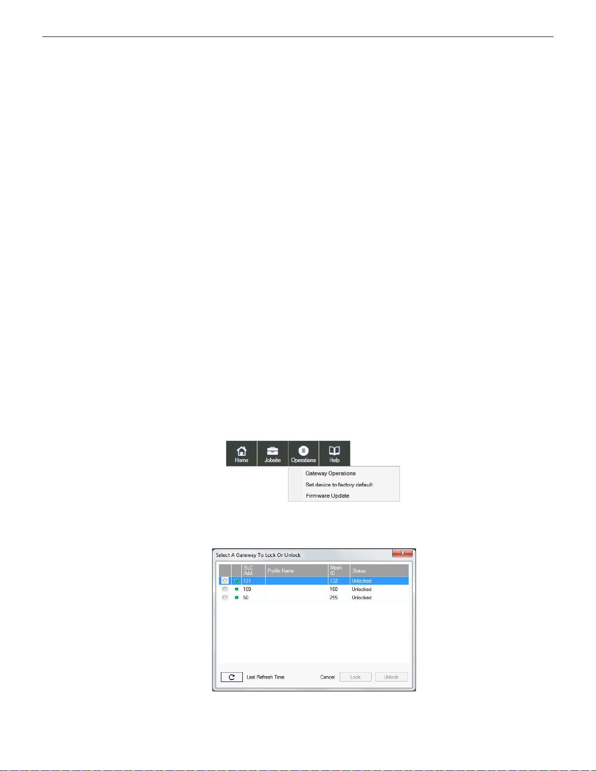
W-GATE Wireless Gateway Operations
Figure 2.18 Operations Menu
operations.jpg
lock_unlcok_gateway.jpg
Figure 2.19 Lock/Unlock Screen
Mesh Restructuring Mode
In addition to the initial mesh restructuring mode, mesh restructuring i s automati cally perform ed after any restoration of comm unication
to a device or to recover from a link failure (Class A fault). Mesh restructuring that occurs during normal mode does not generate a trouble message. During mesh restructuring, fire pro tection is provi ded by all devices that are participating in the mesh communication. The
gateway reports “Restructuring” to the communicator display of the SWIFT Tools application.
Bootloader Mode
The gateway enters the bootloader mode when its firmware is being updated using SWIFT Tools. The gateway does not communicate
with the F ACP during bootloader mode. The gateway reports “Bootloader” to th e communi cator dis play of the SWIFT Tools application.
Mesh Upgrade
Starting with version 3.0, firmware updates for the wireless mesh devices (detectors, monitor module, relay, etc.) can be broadcast over
the mesh network. Fire protection will not be provided during the upgrade process.
SWIFT tools will be used to initiate and monitor the upgrade process. During the upgrade process each device in the mesh will appear as
a no answer or invalid reply. Refer to Section E.4 on page 76 for more information on the mesh upgrade process.
Neighboring Network Scan
A Mesh network will identif y adja cent mesh networks for the purpose of avoiding communication collisions and for time synchronization to ensure end-to-end latency compliance. Fire protection will be provided during a neighboring network scan by all devices that are
participating in the mesh communication. The gateway reports “Neighboring Scan” to the communicator display of the SWIFT Tools
application.
2.9.2 LED Patterns
The LED indicator patterns are provided in Appendix D on page 67.
2.9.3 Lock/Unlock the Gateway
The gateway can be locked to prevent access to the magnetic sensors and to password-protect all wireless interactions. The lock function
can be performed by SWIFT Tools. When SWIFT Tools is used to lock the gateway, a password must be provided for all future interactions, including unlocking the gateway. If the gateway was previously loc ked with a password from SWIFT Tools, the previous password will be applied. Use this password for all future interactions with the SWIFT Tools application.
Lock/Unlock the Gateway Using SWIFT Tools
To lock/unlock the gateway:
1. Connect the W-USB device to your computer. For more information on the W-USB adapter, refer to Section 6.
2. Launch the SWIFT T ools applicati on. Refer to AppendixA, “SWIFT Tools” for more information.
3. From the Home Screen, select the Site Sur v ey , Create Mesh Network, or Diagnostics function.
4. Click Operations. The following screen is displayed.
5. Select Gateway Operations to lock/unlock the gateway. The Lock/Unlock Gateway screen displays the list of gateway/gateways
that are in the range of the W-USB adapter connected to your /Laptop.
6. Select desired gateway and click Lock or Unlock as required.
22 SWIFT® Smart Wireless Integrated Fire Technology Manual — P/N LS10036-000FL-E:J 4/13/2020
Page 23
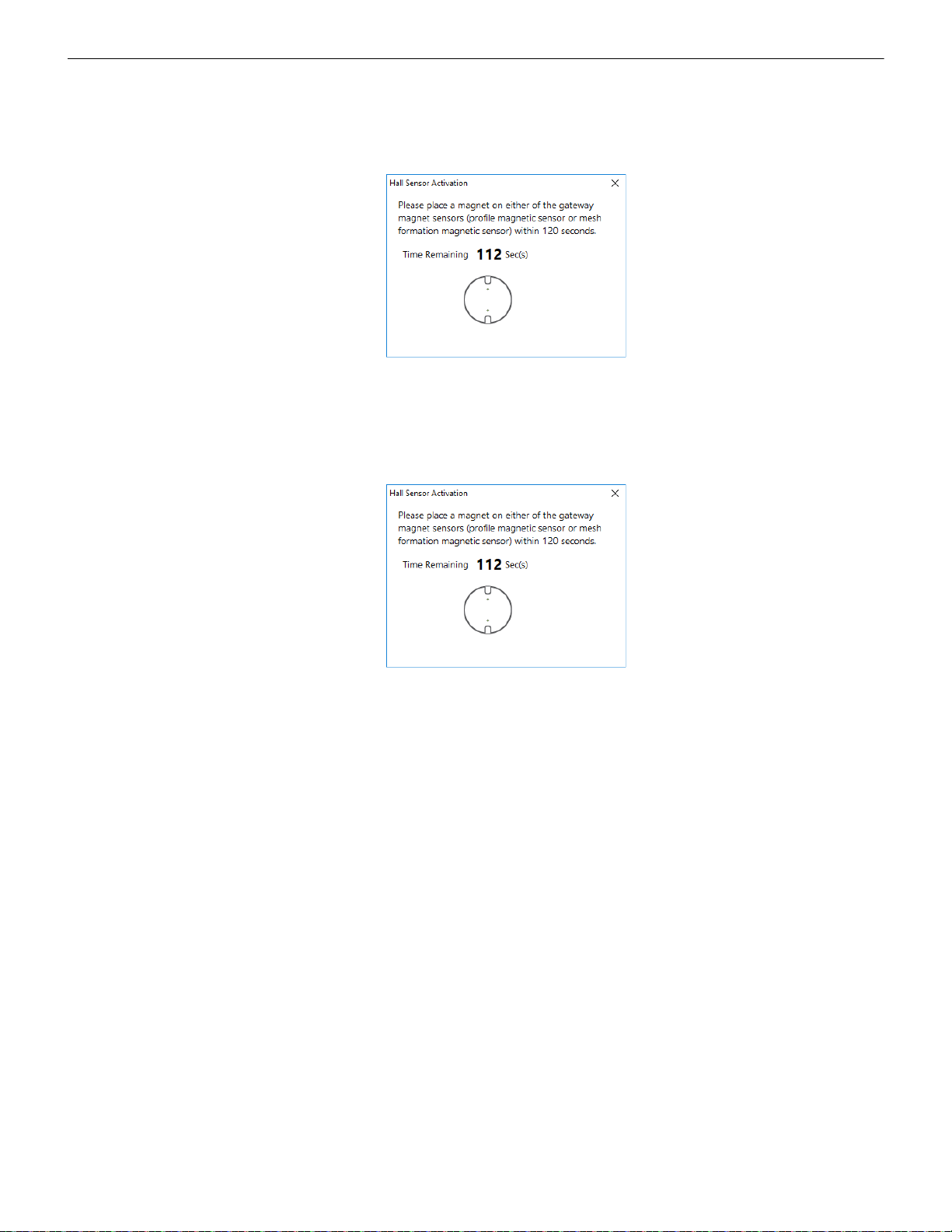
Operations W-GATE Wireless Gateway
hall sensor.png
hall sensor.png
• To lock the gateway
1. Click Lock. The Gateway Password screen is displayed.
2. Enter the verification password in the Verification Password field and click OK.
3. A Hall Sensor Activation window displays. The LED on the gateway blinks yellow indicating the gateway is waiting for
hall sensor activation.
4. Place a magnet on either of the gateway sensors within 120 seconds.
5. The LED blinks normal upon hall sensor activation. The gateway is locked and a confirmatory message is displayed.
• To unlock the gateway
1. Click Unlock. The Gateway Password screen is displayed.
2. Enter the verification password in the Verification Password field and click OK.
3. A Hall Sensor Activation window displays. On hall sensor activation, the LED on the gateway blinks yellow.
4. Place a magnet on either of the gateway sensors within 120 seconds.
5. The LED blinks normal upon hall sensor activation. The gateway is unlocked and a confirmatory message is displayed.
Password Reset
To reset the password, contact technical support.
2.9.4 Enable/Disable Max Gateway Trouble Reporting
This feature is used to determine if the permitted number of Honeywell SWIFT systems that can co-exist in range of each other without
reducing overall performance has been exceeded. The default setting is On (enabled).
Completed Wireless Network
Turning off the MAX GATEWAY trouble reporting in this case prevents subsequent installation attempts from causing a trouble on a
properly installed and commissioned system. When the wireless installation is completed and there are no possibilities of overlapping
systems, turn off MAX GATEWAY trouble reporting when all three of the following conditions are true:
1. The entire fire system installation has been com p leted.
2. There is no MAX GATEWAY trouble indication present in the completed system.
3. The system has been inspected, tested, and approved by the authority having jurisdiction.
Possible Wireless Mesh Overlap
Generally, only four SWIFT wireless mesh gateways, along wi th their associated devices, are permitted to be installed within an overlapping wireless region. The MAX GATEWAY trouble is generated when a fifth gateway mesh is detected and the maximum limit is
exceeded. When there is a MAX GATEWAY trouble present in the system, it is permit ted to turn of f MAX GATEWAY trouble reporting
after completing the following evaluation method with successful results. For the result to be successful, the signal strength between
devices in any one mesh must be at least 20 dB stronger than the signals seen from another mesh. If the 20 dB requirement is not met, or
if the evaluation cannot be performed due to access restrictions, the number of overlapping mesh systems must be reduced to four to
ensure the wireless system performs according to UL requirements. This could mean that additio nal mesh systems c annot be instal led in
the area.
SWIFT® Smart Wireless Integrated Fire Technology Manual — P/N LS10036-000FL-E:J 4/13/2020 23
Page 24
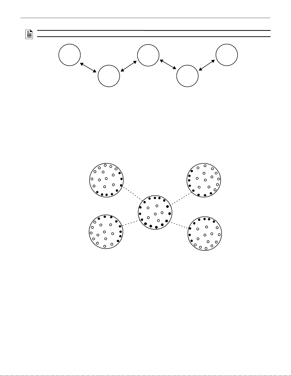
W-GATE Wireless Gateway Operations
mesh
#1
mesh
#2
mesh
#4
mesh
#3
mesh
#5
-
2
0
d
B
-
2
0
d
B
-
2
0
d
B
-
2
0
d
B
Figure 2.20 Basic Overlapping Mesh Example
Figure 2.21 Perform a Link Test with the Fifth Mesh
Mesh #1
Mesh #2
Mesh #5
Mesh #4
Mesh #3
NOTE: Signal strength is represented using negative numbers. So, 30 is 20 dB stronger than 50. Refer for Figure 2.23 for an example.
Evaluation Process
1. Locate all the SWIFT wireless mesh systems in the area. Access to all mesh gateways in the area and to the closest edge devices
between overlapping meshes is required and the SLC addresses of the edge devices must be known. The edge devices that must be
accessible are located at the ends of the dotted lines represented in Figures 2.21 and Figure 2.24. If location of devices or access to
them is not possible, the addition of a fifth wireless mesh is not permitted in this area.
2. Identify the devices on the edge of each mesh.
3. Find the closest edge device from each mesh to the closest edge of the new mesh. Except as noted in Figure 2.25, four pairs of
devices should be identified given there are five overlapping meshes in the area.
4. Perform a link test between each of the four device locations (Mesh 1 to Mesh 5, Mesh 2 to Mesh 5, Mesh 3 to Mesh 5, and Mesh 4
to Mesh 5) using a separate pair of test devices. Refer to Appendix B, “Site Survey” for instructions on how to perform a site
survey. Use SWIFT Tools to identify the signal strength/link quality for each of the four link tests and record these values.
24 SWIFT® Smart Wireless Integrated Fire Technology Manual — P/N LS10036-000FL-E:J 4/13/2020
Page 25

Operations W-GATE Wireless Gateway
Figure 2.22 Perform Link Test within Each Mesh
Mesh #1
Mesh #2
Mesh #5
Mesh #4
Mesh #3
Figure 2.23 Review Network Statistics
In this case, 25 would be the stronger link.
5. Use network statistics from the gateway to determine link strength between edge devices in each mesh.
6. Export network statistics to Excel for each gateway, and by using the SLC address tab for each edge device, review the primary and
secondary parent link strengths for each edge device in each mesh system.
7. Make a list of the strongest links for all edge devices in each mesh.
8. From the collection of values recorded in step 7, identify the lowest value on the list of thes e links in each mesh.
9. Compare that lowest value from each mesh to the corresponding link values in step 4.
10. If the values in step 8 are at least 20dB higher that the values in step 4, continue to step 11. If they are not, installation of Mesh #5 is
not allowed.
SWIFT® Smart Wireless Integrated Fire Technology Manual — P/N LS10036-000FL-E:J 4/13/2020 25
Page 26

W-GATE Wireless Gateway Operations
Figure 2.24 Perform a Link Test Across Existing Mesh Networks
Mesh #1
Mesh #2
Mesh #5
Mesh #4
Mesh #3
horizontal- adjacent buildings
high-rise building
mesh #1
m
esh #1
mesh #2
mesh #3
mesh #4
mesh
#5
m
esh #2
mesh #
4
mesh #3
m
e
s
h
#
5
m
e
s
h
#
4
m
e
s
h
#
3
m
e
s
h
#
3
m
e
s
h
#
2
m
e
s
h
#
1
m
e
s
h
#
4
m
e
s
h
#
1
m
e
s
h
#
2
Figure 2.25 Perform a Link Test in High-rise/Adjacent Bu il din gs
Note: Additional mesh networks can be installed in
adjacent buildings/stories in the high-rise (beyond
the five depicted here), provided the restrictions for
overlapping mesh networks are met.
11. Repeat this process from step 4, identifying device pair locations for each mesh (Mesh 1 to Mesh 2, Mesh 1 to Mesh 3, Mesh 1 to
Mesh 4, Mesh 2 to Mesh 3, Mesh 2 to Mesh 4, and Mesh 3 to Mesh 4).
12. If all the values are at least 20 dB higher in step 10, MAX GA TEWAY trouble reporting can be disabled.
NOTE: If the mesh networks are installed vertically in a high-rise building or horizontally in adjacent buildings, the evaluation in steps
4-11 only needs to be performed on the mesh edge devices between different meshes on adjacent floors.
Disabling Max Gateway Reporting
Once the criteria for disabling MAX GATEWAY troubles are met, follow the steps below to turn off reporting. Reporting must be disabled for every gateway in the area.
1. Connect the W-USB device to your computer. For more information on the W-USB adapter, refer to Section 6.
2. Launch the SWIFT Tools application. Refer to Appendix A, “SWIFT Tools” for more information.
3. From the Home Screen, select the Diagnostics function.
4. Select a Gateway from the communicator panel.
5. Click View Mesh. SWIFT Tools will display Lock/Unlock option. Refer to Section 2.9.3 on page 22 for additional information.
26 SWIFT® Smart Wireless Integrated Fire Technology Manual — P/N LS10036-000FL-E:J 4/13/2020
Page 27
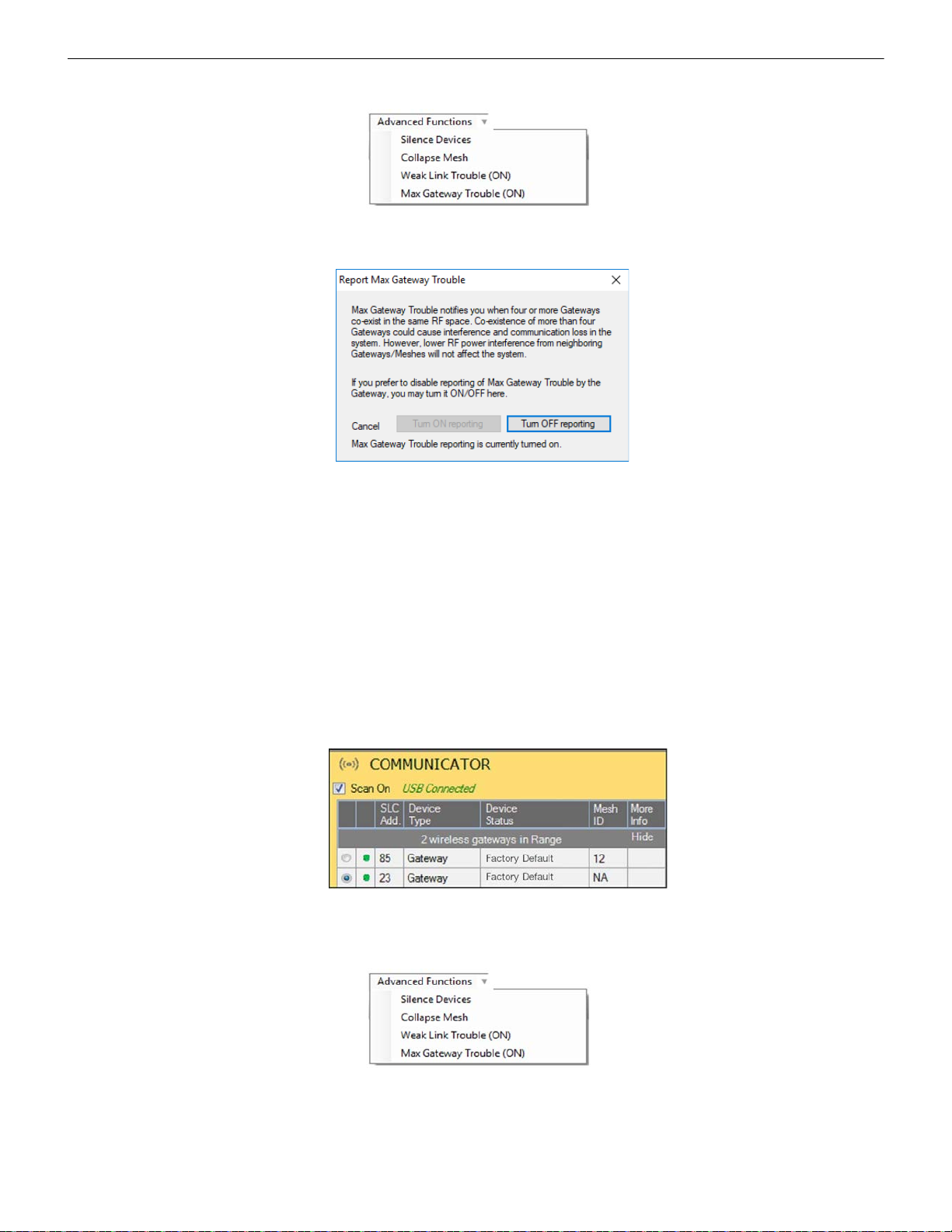
Operations W-GATE Wireless Gateway
advfuncdrop.wmf
Figure 2.26 Advanced Functions Options
Figure 2.27 Report Max Gateways Troubles Option
Figure 2.28 Communicator Panel
selcomm.png
advfuncdrop.wmf
Figure 2.29 Advanced Functions Options
6. Click Advanced Functions. A drop-down list is displayed.
7. Click Max Gateway troubles (On). The Max Gateway troubles screen is displayed.
8. Click Turn off reporting. The trouble reporting is now disabled.
2.9.5 Weak Link Trouble Reporting
The SWIFT Network uses two paths of communication for each device. To establish the link between devices as a viable communication
path, the signal strengths must meet the limits provided in Section 2.3. The SWIFT Network implements a higher threshold for primary
connections to provide an extra layer of robustness and immunity from interference. A weak link trouble condition is initiated for any
device that does not have at least one connection at the primary threshold. This is an optional setting that can be disabled to ignore the
weak link trouble condition. The trouble can be disabled at the gateway.
Disable Trouble Reporting at the Gateway Using SWIFT Tools
To disab le trouble reporting at the gateway through SWIFT Tools:
1. Connect the W-USB device to your computer. For more information on the W-USB adapter, refer to Section 6.
2. Launch the SWIFT Tools application. Refer to Appendix A, “SWIFT Tools” for more information.
3. From the Home Screen, select the Diagnostics function.
4. Select the desired gateway from the communicator panel.
5. Click View Mesh. SWIFT Tools will display Lock/Unlock option. Refer to Section 2.9.3 on page 22 for additional information.
6. Click Advanced Functions. A drop-down list is displayed.
SWIFT® Smart Wireless Integrated Fire Technology Manual — P/N LS10036-000FL-E:J 4/13/2020 27
Page 28

W-GATE Wireless Gateway Operations
Figure 2.30 Report Weak Links Troubles Option
!
advfuncdrop.wmf
Figure 2.31 Advanced Functions Options
Figure 2.32 Collapse Mesh Network Option
7. Click Weak links troubles (On). The Report weak links troubles screen is displayed.
8. Click Turn off reporting. The trouble reporting is now disabled.
2.9.6 Collapse Network Command
The collapse command is a diagnostic function to break the mesh network. All devices will retain the profile information but will be
removed from the mesh. The mesh can be reformed by activating mesh formation.
CAUTION: FIRE PROTECTION DISABLED
FIRE PROTECTION FROM WIRELESS DEVICES IS DISABLED WHEN A COLLAPSE NETWORK COMMAND IS
ISSUED.
Collapse Mesh Network Using SWIFT Tools
To collapse the mesh network using the SWIFT T ools:
1. Connect the W-USB device to your computer. For more information on the W-USB adapter, refer to Section 6.
2. Launch the SWIFT T ools applicat ion. Refer to AppendixA, “SWIFT Tools” for more information about the programming utility.
3. From the Home Screen, select the Diagnostics function.
4. Select a Gateway from the communicator panel.
5. Click View Mesh. SWIFT Tools will display Lock/Unlock option. Refer to Section 2.9.3 on page 22 for additional information.
6. Click Advanced Functions on top of the mesh display. A drop-down list is displayed.
7. Click Collapse Mesh. The Collapse mesh network screen is displayed.
28 SWIFT® Smart Wireless Integrated Fire Technology Manual — P/N LS10036-000FL-E:J 4/13/2020
Page 29
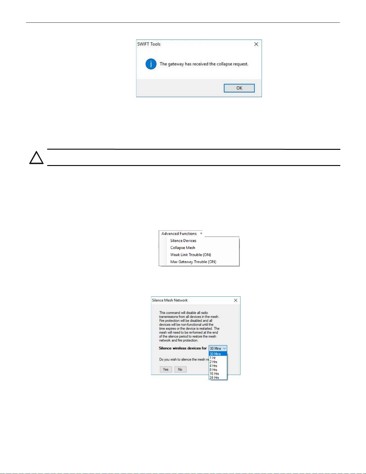
Operations W-GATE Wireless Gateway
Figure 2.33 Collapse Mesh Network Confirmation
!
advfuncdrop.wmf
Figure 2.34 Advanced Functions Options
Figure 2.35 Silence Mesh Network Screen
8. The network is now collapsed and a confirmation message is displayed as shown below.
2.9.7 Silence Network Command
The silence network command is a diagnostic function to turn off all radio communication from the wireless devices for a set amount of
time. All devices will re tain the profile information but will be removed from the mesh. The devices will not send or receive any wireless
communication until the set time expires or the device is rebooted. The mesh network can be reformed at the end of the silence period or
after the device is restarted.
CAUTION: FIRE PROTECTION DISABLED
FIRE PROTECTION FROM WIRELESS DEVICES WILL BE DISABLED WHEN A SILENCE COMMAND IS ISSUED.
Silence Mesh Network Using SWIFT Tools
To silence the mesh network:
1. Connect the W-USB device to your computer. For more information on the W-USB adapter, refer to Section 6.
2. Launch the SWIFT Tools application. Refer to Appendix A, “SWIFT Tools” for more information on the programming utility.
3. From the Home Screen, select the Diagnostics function.
4. Select a Gateway from the communicator panel.
5. Click View Mesh. SWIFT Tools will display Lock/Unlock option. Refer to Section 2.9.3 on page 22 for additional information.
6. Click Advanced Functions on top of the mesh display. A drop-down list is displayed.
7. Click Silence Devices. The Silence mesh network screen is displayed.
8. Select the time interval to silence the wireless devices from the dropdown list and click Yes.
SWIFT® Smart Wireless Integrated Fire Technology Manual — P/N LS10036-000FL-E:J 4/13/2020 29
Page 30

W-GATE Wireless Gateway Operations
Figure 2.36 Silence Mesh Network Confirm a tio n Me ss a ge
9. The network is silenced and confirmation is displayed as shown below.
2.9.8 Overlapping Wireless Sensor Networks and Limitations
The SWIFT Network technology shares the RF spectrum with other Honeywell Fire Wireless Sensor Network systems. Honeywell Fire
has generally established a limit of 4 overlapping networks (4 gateways maximum and their associated devices) to avoid congestion in
the RF spectrum. If more than 4 networks are detected, a MAX GATEWAY system trouble will be generated. To resolve this trouble, any
instances of disruptive overlap need to be removed. Refer to Appendix C, “Troubleshooting and Testing” for suggestions on removing
overlap between wireless networks. The trouble will be self-restoring up to 36 hours after the condition is resolved. To expedite the trouble resolution, transition the network that is reporting the trouble in and out of mesh formation mode.
2.9.9 Activation of Wireless Output Devices
Wireless input modules (pull stations and monitor modules) may be programmed to activate wired notification appliances anywhere in
the system and wireless input modules may be programmed to activate wireless output devices including relay modules, sync modules,
and AV devices within the same wireless mesh network. Wireless input modules are not permitted to be programmed to activate wireless
outputs in another wireless mesh. Wireless detector programming is not restricted since the alarm condition is determined by the fire
panel.
2.9.10 Avoiding RF Interference
The SWIFT wireless mesh network uses radio frequency hopping spread spectrum technology to communicate in the 900 MHz ISM
band (902MHz to 928MHz). Other commercial and industrial products also operate in this band. If two-way radios or other wireless
communication devices are used during the installation process, it is recommended that they be kept at least 4 feet away from the
Fire•Lite wireless devices or that they operate on a different frequency band to ensure rapid mesh formation.
A properly installed SWIFT wireless mesh network with primary link reporting enabled will be highly immune to RF interference from
other wireless products even when they are nearby. The use of the weak link reporting feature is highly recommended. If the system is
installed in a controlled environment where other 900 MHz ISM band devices will not be present, the primary link reporting feature may
be disabled to permit greater distances between installed devices if required.
The SWIFT wireless mesh network will be able to automatically de tect and avoid certain types of in-band channel interference (often
caused by two-way radios) by using an alternate channel set. The system will log detection and avoidance of this kind of interference in
the gateway history as “Walkie Talkie Mode” Entry or Exit.
30 SWIFT® Smart Wireless Integrated Fire Technology Manual — P/N LS10036-000FL-E:J 4/13/2020
Page 31
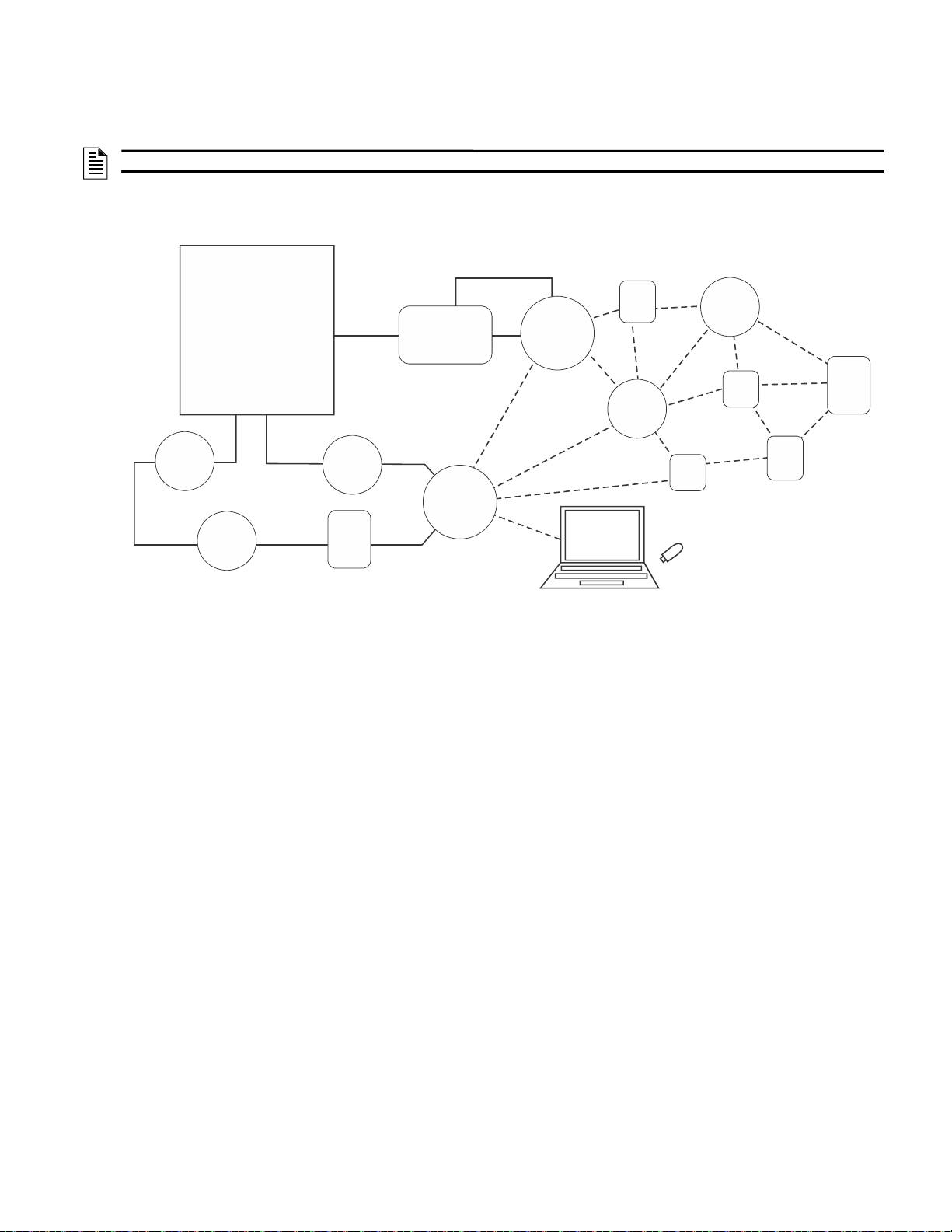
The SWIFT W ireless Sensor Network includes a W-DIS-D (Wireless Display Driver). The W-DIS-D and an ANN-80-W are required for
Figure 3.1 SWIFT Network
FACP
ANN-80-W
SLC
wired SLC devices
W-GATE
Gateway
SWIFT ANN Bus
ANN Bus
Driver
(W-DIS-D)
wireless mesh
network
SWIFT
Tools
W-USB
24VDC
Supply
the display of wireless-specific events. This section describes the wireless user interface display driver and how it is connected to the
ANN-80-W. In addition, this section provides information on how to install, configure, and monitor the messages on the ANN-80-W.
NOTE: The W-DIS-D and ANN-80-W are not required for use with the ES-50X or ES-200X FACPs.
3.1 Description
The W-DIS-D and ANN-80-W are required for the display of wireless-specific events.
Section 3: W-DIS-D Wireless Display Driver
The W-DIS-D is a part of the wireless network and has a specific SLC module address. The W -DIS-D and ANN-80-W display the wireless specific events that cannot be displayed on the FACP. These wireless events are related to the trouble and supervisory conditions that
are specific to the gateway and its devices. The wireless events are indicated at the FA CP as a generic trouble or as a supervisory event
via the gateway using the base address +1 and the base address +2 for supervisory and trouble events respectively. The specific event
details are sent to the ANN-80-W via the SWIFT ANN-BUS from the display driver. Th e following conditio ns lead to the trouble and
supervisory events.
Trouble Events
• Jamming (device communication loss due to RF interference)
• Duplicate address
• Battery low
• Class A missing second link
• Weak link low signal strength
• Mesh Restructuring
• Wireless mesh formation in progress
•RF comm loss
• Illegal address
• Maximum Gateway
• Maximum devices
• RF Device No Answe r
Supervisory Event
• Tamper
SWIFT® Smart Wireless Integrated Fire Technology Manual — P/N LS10036-000FL-E:J 4/13/2020 31
Page 32

W-DIS-D Wireless Display Driver Agency Approvals
!
3.2 Agency Approvals
3.2.1 FCC
This device complies with part 15 of the FCC Rules. Operation is subject to the following two conditions:
1. This device may not cause harmful interference, and
2. This device must accept any interference received, including interference that may cause undesired operation.
FCC ID: PV3WFSLCDUI
WARNING: DO NOT MAKE CHANGES TO THE EQUIPMENT
CHANGES OR MODIFICATIONS NOT EXPRESSLY APPROVED BY THE MANUFACTURER COULD VOID THE USER’S
AUTHORITY TO OPERATE THE EQUIPMENT.
3.2.2 Federal Institute of Telecommunications
This device utilizes the Honeywell915 rev A radio module and complies with IFETEL standard(s).
IFT: RCPHOSW14-1983
3.3 Specifications
Following are the specifications for the display driver.
Specifications Data
Operating Voltage Range 18VDC to 30VDC
Maximum current draw 30 mA
SWIFT ANN-BUS Driver: 1.5V - 3.4V and 60 mA max.
Radio Frequency Lower ISM band (915 MHz)
Maximum power output +17 dBm
Minimum signal strength level needed at the receiver for a primary path with
weak link reporting enabled
Minimum signal strength level needed at the receiver for a secondary path
(minimum signal to noise point) or a primary path with weak link trouble
reporting disabled
Note: All connections are power-limited.
Receiver: 0.2V - 6V
-55 dBm
Must be 18 dBm higher than the noise floor down
to -80 dBm
3.3.1 Environmental Specifications
System Operating Temperature Storage Temperature Humidity
Display Driver 0°C-49°C / 32°F-120°F -10°C-50°C / 14°F-120°F 10 to 93% RH, Non-condensing
For information on the ANN-80-W, refer to the ANN-80 Series Installation Document.
32 SWIFT® Smart Wireless Integrated Fire Technology Manual — P/N LS10036-000FL-E:J 4/13/2020
Page 33
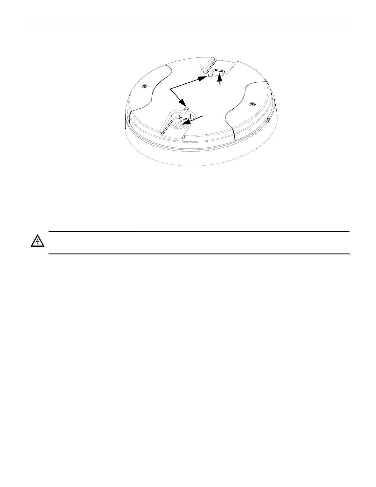
Magnetic Sensors W-DIS-D Wireless Display Driver
Figure 3.2 LEDs and Magnetic Sensors on W-DIS-D
LEDs
Mesh
Formation
Magnetic
Sensor
Profile
Magnetic
Sensor
cover.wmf
!
3.4 Magnetic Sensors
The display driver has two magnetic sensors. The sensors are used to remove a profile as described in Section 3.7.3 or to request a profile
as described in Section 3.7.1.
3.5 Display Driver LED Indicators
The two LEDs on the devices blink in the same pattern to allow the LED to be viewed from any angle. The LED patterns are provided in
Appendix D.
3.6 Mounting & Wiring
3.6.1 Mounting
WARNING: FORMEX SHEET
ENSURE THA T THE FORMEX SHEET INSIDE THE DISPLAY DRIVER IS NOT REMOVED OR TAMPERED WHILE
INST ALLING OR CLEANING.
The display driver has two major pieces, the cover and the mounting plate. The mounting plate is mounted to the wall or ceiling and field
wiring is connected to it. The cover contains the PC board and is fastened to the mounting plate once the wiring is connected.
Mount the mounting plate directly to an electrical box on the ceiling or wall. The plate mounts directly to a 4˝ square (with and without
plaster ring), 4˝ octagon, 3 1/2˝octagon, single gang or double gang junction boxes. If an electrical box is not available, the mounting
plate can be mounted to any flat surface and the wiring can be connected via the knockout points in the mounting plate.
To mount the display driver:
1. Pull the wiring through the opening in the mounting plate.
2. Mount the mounting plate to the junction box or ceiling. See Figure 3.3 below.
3. Connect field wiring to the terminals, as described in Section 3.6.2.
4. Connect necessary jumpers where applicable. Refer to Section 2.7.3.
5. To mount the cover, align the locating pins on the cover to the corresponding slots in the mounting plate. See Figure 3.4.
SWIFT® Smart Wireless Integrated Fire Technology Manual — P/N LS10036-000FL-E:J 4/13/2020 33
Page 34
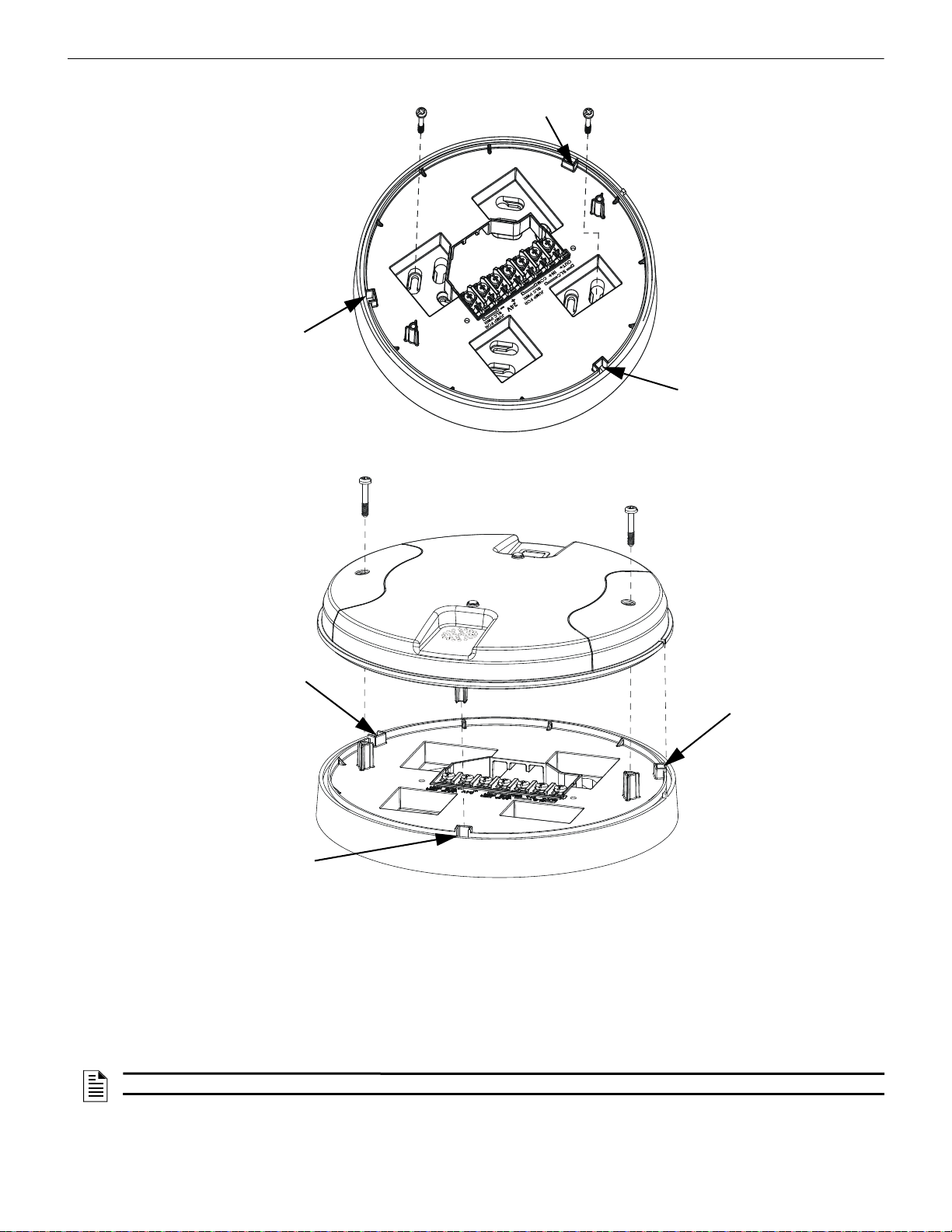
W-DIS-D Wireless Display Driver Mounting & Wiring
Figure 3.3 Mounting Plate for Wireless Display Driver
2.2.wmf
locating pin
locating pin
locating pin
Figure 3.4 Attaching Cover to Mounting Plate
2.3.wmf
locating pin
locating pin
locating pin
6. Secure the cover by tightening the mounting screws.
3.6.2 Wiring
• All wiring must be installed in compliance with the National Electrical Code and the local codes having jurisdiction.
34 SWIFT® Smart Wireless Integrated Fire Technology Manual — P/N LS10036-000FL-E:J 4/13/2020
• 12-18 AWG is recommended.
• Maximum wiring distance is 6,000 ft. (1,829 m).
For wiring connections:
1. Strip about 3/8” of insulation from the end of the wire.
2. Slide the stripped end of the wire under the appropriate terminal and tighten the screw.
NOTE: Do not loop the wire under the screw terminals.
Page 35
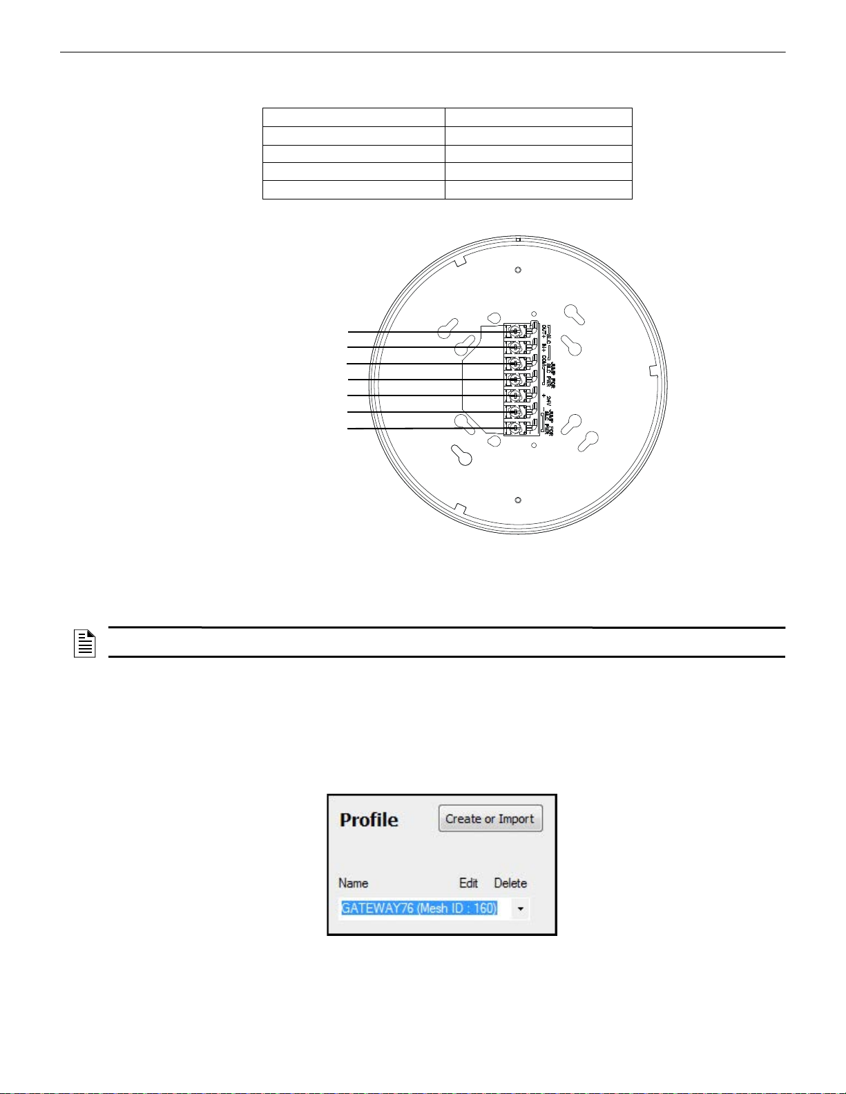
Configuration W-DIS-D Wireless Display Driver
Figure 3.5 W-DIS-D Mounting Plate - Terminal Layout
A7 - B (SWIFT ANN-BUS)
A6 - A (SWIFT ANN-BUS)
A5 - not used
A4 - not used
A3 - Power +24VDC
A2 - Power Ground
A1 - not used
2.4.wmf
Figure 3.6 Creating or Importing a Profile
assignprofile_select.jpg
The ANN-80-W and display driver require regulated +24VDC power supplied by either the host FACP or by a remote power supply.
Connect the display driver to the ANN-80-W as described in the table and graphic below
Display Driver Terminals ANN-80-W Series Terminals (TB1)
External power ground Terminal 1 (-)
External power +24VDC Terminal 2 (+)
A (SWIFT ANN-BUS) Terminal 3 (A)
B (SWIFT ANN-BUS) Terminal 4 (B)
Table 3.1 Wiring the Display Driver to the ANN-80-W Series
3.7 Configuration
The configuration of the display driver starts with assigning a profile. Assign the profile using SWIFT Tools.
NOTE: To assign a profile, the display driver must be in a factory default state. This is confirmed by a single red light that flashes on the
LED. To restore the display driver to factory default state, refer to Section 3.7.3.
3.7.1 Assign a Profile
To assign a profile to the display driver using SWIFT Tools:
1. Connect the W-USB device to your laptop. For more information on the W-USB adapter, refer to Section 6, “W-USB Adapter”.
2. Launch SWIFT Tools. Refer to Appendix A for more information.
3. From the Options Screen, select the Create Mesh Network function.
4. Create a new profile or Import an existing profile as required.
5. Select and open the profile to be assigned to the display driver from the Name drop-down box in the Profile section.
6. Power on the display driver within approximately 20 feet of the laptop running SWIFT Tools.
7. Ensure that the Scan On selection box in the Communicator W indow is checked.
SWIFT® Smart Wireless Integrated Fire Technology Manual — P/N LS10036-000FL-E:J 4/13/2020 35
Page 36

W-DIS-D Wireless Display Driver Configuration
Figure 3.7 Selecting the Display Driver
assignprofiledisp.png
Figure 3.8 Assigning a Profile
assignprofdisp2.png
Figure 3.9 Operations Menu
8. Select the display driver from the Communicator Window. The display driver is listed by its generic name, “Display Driver”.
9. Click Assign.
The display driver is now included in the list of devices with a profile assigned. The LEDs on the display driver will turn on green for 10
seconds after the profile has been received.
3.7.2 Mesh Formation
To add a display driver to a mesh, refer to “Create a Mesh Network” on page 18 or “Mesh Formation” on page 21.
3.7.3 Removing Profiles
Restoring to Factory Default Without Using SWIFT Tools
To remove a profile without using SWIFT Tools:
1. Start with the device powered off. The process is performed during start-up.
2. Power on the display driver using regulated, external +24V.
3. Verify the display driver is in the profile modification state. Both the LEDs on the display driver double blink yellow every second
for ten seconds in the profile modification state.
4. Activate both the magnetic sensors within ten seconds of starting up the display driver while the double yellow blink is active in the
display driver. If the ten second window is missed, power down the display driver and repeat the process starting at step 1.
5. The LEDs on the display driver will blink green every second for five seconds indicating that the profile is removed.
After following the above steps, the profile is erased and the display driver returns to factory default state.
Restoring to Factory Default Using SWIFT Tools
To remove a profile using SWIFT Tools:
1. Connect the W-USB device to your laptop. For more information on the W-USB adapter, refer to Section 6.
2. Launch SWIFT Tools. Refer to Appendix A for information.
3. From the options menu, select the Site Survey, Create Mesh Network, or Diagnostics function.
4. Click Operations and select Set device to factory default.
36 SWIFT® Smart Wireless Integrated Fire Technology Manual — P/N LS10036-000FL-E:J 4/13/2020
Page 37

ANN-80-W Configuration W-DIS-D Wireless Display Driver
resetdevices_dd.png
Figure 3.10 Reset Devices Menu
5. The Reset Devices screen appears, displaying the display driver and other devices that have a profile assigned. Click to select the
required device and click Reset Device to remove the profile.
The profile is removed and the device is reset to the factory default state.
3.8 ANN-80-W Configuration
To configure the ANN-80-W, set the dip switch address on the ANN-80-W to 1 when it is connected to the display driver. For more
information on setting addresses on the ANN-80-W, refer to the ANN-80 Series Product Installation Document.
3.9 Display Driver Operations
Ta ble3.2 outlines the wireless related events and the description at each display.
Events FACP Displays: Annunciator Displays:
Alarm (Detector or Module activations) Address specific to the initiating device. No Display
Tamper Generic Supervisory at GW +1 address Specific device with SLC address
RF related trouble conditions - Jamming,
Battery Low, Duplicate address, Class-A
missing second link, Weak link low signal
strength.
Wireless Device Missing from network No Answer/Invalid response for the specific
Gatewayinitializing, wireless mesh formation in
progress.
Illegal address Generic Trouble GW +2 address Address zero
Mesh capacity exceeded Generic Trouble GW +2 address Gateway base address
RF comm loss “No Answer” / “Invalid response” for the Display
Annunciator lost connection Open circuit at Display Driver SLC Address “Key Bus Trouble”
Normal No Display Mesh ID number
Generic Trouble GW +2 address Specific device with SLC address
“RF Device No Answer”
SLC Address
Generic Trouble GW +2 address “Gateway Initialization”
Driver SLC Address
(no address specified)
(no address specified)
“RF Comm Loss”
Table 3.2 Event Display Location Table
NOTE: One display driver is required for one gateway. Multiple gateway installations require a display driver for each gateway.
SWIFT® Smart Wireless Integrated Fire Technology Manual — P/N LS10036-000FL-E:J 4/13/2020 37
Page 38

W-DIS-D Wireless Display Driver ANN-80-W Operations
3.9.1 Modes of Operation Not in a Mesh Network
Bootloader
In this mode, the display driver cannot participate in a mesh and cannot provide fire protection. The display driver will be available in the
communicator window of SWIFT Tools with a status “Bootloader”. To get a device out of bootloader, refer to Section C.1, “Troubleshooting”.
Factory Default
In this mode, the display driver is not associated with the gateway. For further information on assigning a profile, refer to Section 3.7.1.
In this mode, the display driverwill be viewable in the communicator window of SWIFT Tools with a state of “Factory Default”. The
ANN-80-W will display RF COMM LOSS when the display driver is at Factory Default state.
Profile Configured
In this mode, the display driver is associated with the gateway but is not an active participant in the mesh network. For further information on mesh formation, refer to, “4.5.2, "Mesh Formation". T o remove a profile from adisplay driver, refer to section, “3.7.3, "Removing
Profiles". In this mode, the display driver will be viewable in the communicator window of SWIFT Tools with a state of “Active Scan”.
The ANN-80-W will display RF COMM LOSS when the display driver is at factory default state.
3.9.2 Modes of Operation as a Mesh Participant
Mesh Formation Mode
In this mode, the display driver is an active participant in a mesh that is forming. The LED will blink green then blink yellow every 7
seconds. For further information on mesh formation mode, refer to, “4.5.2, "Mesh Formation". The display driver will not communicate
directly with SWIFT Tools for display in the communicator. The status of the display driver must be obtained via the gateway. The
ANN-80-W will display ‘Mesh Formation in Progress’ during mesh formation mode.
Initial Mesh Restructuring Mode
In this mode, the mesh network is formed and is in the process of establishin g stronger communication paths. The LED will blink yellow
every 7 seconds. For further information on initial mesh restructuring mode, refer to the topic, "Initial Mesh Restructuring Mode". The
display driver will not communicate directly with SWIFT Tools for display in the communicator. The status of the display driver must be
obtained via the gateway. The ANN-80-W will display Gateway Initializing during the initial mesh restructuring mode.
Normal Mode
In this mode, the mesh network formation is complete. The LED will blink green every 14 seconds. If a device is in trouble, it will be
displayed at the ANN-80-W or the FACP. For information, refer to Section 3.10.3, “Event Messages”. The display driver will not communicate directly with SWIFT Tools for display in the communicator . Th e status of the display driver must be obtained via the gateway.
The ANN-80-W will display the mesh ID when the system is normal, or will display a wireless event as specified in Section 3.10.3,
“Event Messages”.
Rescue Mode
In this mode, devices that are active participants in the mesh search and retrieve the devices that have lost the communication link. The
rescue mode is indicated by the a green blink every 7 seconds. For more information on rescue mode refer to “Section 2.9.1, “Modes of
Operation” The display driver will not communicate directly with the SWIFT Tools for display in the communicator. The status of the
display driver must be obtained via the gateway. The ANN-80-W will display the mesh ID when the system is normal, or will display a
wireless event as specified in 3.10.3, "Event Messages".
3.9.3 SLC Operation
Program the SLC point on the display driver as a monitor point. When the communication to the ANN-80-W is missing or disrupted, the
SLC point will indicate an open circuit but will not initiate an alarm condition. Ref er to Figure 2.16 on page 20 for instructions on setting
the address wheels.
3.9.4 LED Patterns
The LED indicator patterns are provided in Appendix D on page 67.
3.10 ANN-80-W Operations
The ANN-80-W displays wireless-specific events for the associated mesh network. Alarm conditions and trouble events that are displayed by the FACP are not displayed at the ANN-80-W. The ANN-80-W incorporates an automatic resound of the piezo and trouble
indicator every 4 hours for active events.
38 SWIFT® Smart Wireless Integrated Fire Technology Manual — P/N LS10036-000FL-E:J 4/13/2020
Page 39
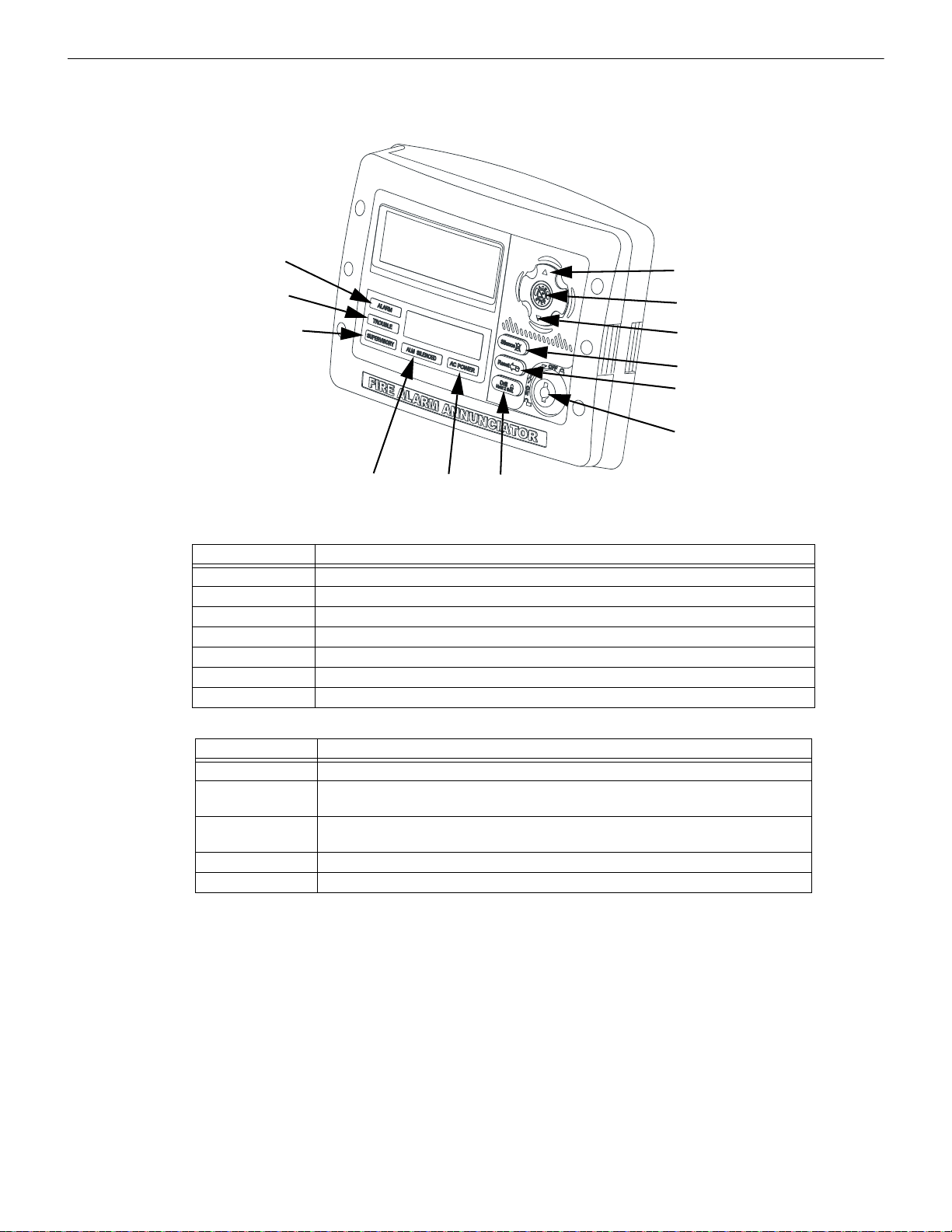
ANN-80-W Operations W-DIS-D Wireless Display Driver
Figure 3.11 Buttons and Indicators on the ANN-80-W
Up Arrow
Acknowledge
Down Arrow
Silence
Reset
Keyswitch shown
in OFF position
Drill
AC Power
Alarm Silenced
Supervisory
Trouble
Alarm
ann-80_iso2.wmf
3.10.1 Annunciator Control Buttons and Visual Indicators
When used as part of a wireless network with the display driver, use of the buttons and indicators on the ANN-80-W diff ers from regular
annunciator function. The button and indicator functions are displayed below and are explained in Tables 3.3 and 3.4.
Up Arrow Press the UP Arrow to scroll up through the messages.
Acknowledge button Press the ACK button to acknowledge the messages and silence the piezo.
Down Arrow Press the Down Arrow to scroll down through the messages.
Silence button Not Used
Reset button Press the Reset button to clear latching wireless events.
Keyswitch Use the Keyswitch to enable the Reset button.
Drill button Not Used
Alarm Not Used
Trouble The trouble LED blinks yellow for any unacknowledged trouble event and it turns on
Supervisory The Supervisory LED blinks yellow for any unacknowledged tamper event, and it turns
Alarm Silenced Not Used
AC Power Not used
3.10.2 Audible Indicators
Wireless events are sent to the FACP as generic trouble or supervisory events by the gateway. Details of those specific events are s ent to
the ANN-80-W by the display driver. The FACP piezo activates for the first trouble event and the first supervisory event. The FACP
piezo will not activate for additional trouble or supervisory events when the initial event is still active. The ANN-80-W piezo will not
activate for the first event but will sound for each event after the first event.
Press the ACK button to acknowledge the event and silence the piezo. The reset function can be enabled in the ANN-80-W using the
keyswitch. To enable the reset button, insert the key into the keyswitch and turn the keyswitch counterclockwise to the ON position.
Button Action
Table 3.3 ANN-80-W Button Functions
Indicator Action
steady for acknowledged trouble events
on steady for acknowledged tamper events
Table 3.4 ANN-80-W Visual Indicators
SWIFT® Smart Wireless Integrated Fire Technology Manual — P/N LS10036-000FL-E:J 4/13/2020 39
Page 40

W-DIS-D Wireless Display Driver ANN-80-W Operations
3.10.3 Event Messages
Wireless network event messages are displayed on the FACP and ANN-80-W. These messages are displayed based on their occurrences.
Use the up arrow and down arrow buttons to scroll through the messages. Trouble and supervisory events that are specific to a device
will specify the device address on the ANN-80-W. The FACP will display a trouble condition for the gateway +2 address for any wireless trouble. The FACP will indicate an activation for the gateway +1 address for any tamper event.
RF Comm Loss
RF COMM LOSS is displayed when the display driver is not in the network. This message is di splayed if the display driver is in bootloader, factory default, or profile assigned mode but not a part of a mesh network. RF COMM LOSS is a non-latching event that will
clear once the display driver joins a mesh network.
Trouble Wireless Mesh Formation In Progress
MESH FORMATION IN PROGRESS is displayed when the network is in mesh for mation mode. MESH FORMATION IN PROGRESS is a non-latching trouble event that will clear once the gateway exits mesh formation mode. The ANN-80-W must join the net-
work to show this message. If the ANN-80-W is not present in the network, RF COMM LOSS is displayed.
Low Battery Event
TROUBLE BATTERY LOW is displayed if:
• a device has a minimum of one week power left to perform the required operations.
Or
• there are less than 4 viable batteries installed.
The low battery event is a latching condition. To clear the low battery event, tamper the device and replace all four batteries. When a
device is tampered, it drops out of the mesh network and attempts to rejoin as soon as the batteries are replaced and the tamper event is
cleared. The wireless device and its address are displayed as a trouble on the ANN-80-W and generic trouble on the FACP. Initiate a
RESET at the ANN-80-W to clear the low battery event .
Trouble Jamming Event
TROUBLE JAMMING displays when a device is overloaded with an interfering RF signal but is able to send outgoing messages. A
jamming event is detected after 20 seconds of exposure to the jamming signal.The jamming event is displayed as a trouble event in the
ANN-80-W and generic trouble event on the F A CP. Jamming is a non-latching trouble. To clear the jamming trouble, remove any interference sources near the point that is reporting the trouble. For more information, refer to AppendixC.
Trouble Duplicate Address
Two wireless devices on the same mesh network that are set to the same address report a TROUBLE DUPLICATE ADDRESS. A
duplicate address is a non-latching trouble that will correct itself once the conflict has been resolved.
Trouble Class A Missing 2nd Link
The TROUBLE CLASS A message denotes a single connection path from the device. The wireless system is a class A system requiring
two communication paths for normal operations. To remedy the class A fault, ensure adequate device spacing or the use of a repeater
may be required. The wireless mesh is a self-healing network. If the trouble is not cleared within 5 minutes, additional actions may be
required. Refer to the troubleshooting section for tips on resolving class A fault conditions.
Trouble Wireless Gateway Initializing
The ANN-80-W displays GATEWAY INITIALIZATION when it is restructurizing for the first time. Gateway initializing is a non-
latching trouble that is active during the first mesh restructuring. The message will clear once the first mesh restructuring routine finishes.
System Normal
The ANN-80-W displays WIRELESS GW DISPLAY and the mesh ID number when the system is functioning normally and there are
no wireless troubles in the system.
Supervisory Tamper
SUPERVISORY TAMPER indicates that a detector is not firmly attached to its base or the cover plate is not properly attached to a
module. The Tamper events are displayed as supervisory events on the ANN-80-W, using the device address, and generic supervisory
events on the F ACP, using Base +2 of the gateway address. Tamper is a latching condition that requires a reset at the ANN-80-W to clear.
Trouble Weak Link Low Signal Strength
TROUBLE WEAK LINK indicates insufficient signal strength. To resolve a weak link, ensure there is adequate device spacing. The
use of a repeater may be required. Tamper any devices when moving them to a new location. Rest art mesh fo rmation once the repeater is
installed or devices rejoin the network, after the tamper is cleared. The gateway will re-evaluate the signal strength connectivity with the
neighboring devices and select suitable signal paths during the subsequent mesh restructuring.
Key Bus Trouble
A KEY BUS TROUBLE indicates that the ANN-80-W has lost connection with the display driver. Does not apply to the ES-50X or ES200X FACPs.
40 SWIFT® Smart Wireless Integrated Fire Technology Manual — P/N LS10036-000FL-E:J 4/13/2020
Page 41

ANN-80-W Operations W-DIS-D Wireless Display Driver
Capacity Exceeded
CAPACITY EXCEEDED indicates that there are alre ady fifty devices present in the mesh and one mo re device is trying to j oin the network.
Maximum Gateways
MAXIMUM GA TEWA YS EXCEEDED indicates that the number of overlapping gateways exceeds the limit of 4. The trouble will be
cleared only when the number of overlapping gateways is reduced to 4 or less. Refer to Appendix C for more information.
RF Device No Answer
RF Device No Answer is a generic trouble event to indicate one or more wireless devices currently or previously have lost communication with the mesh network. RF Device No Answer is a latching event that requires a reset at the ANN-80-W . RF Device No Answer will
be indicated 90 seconds after a device has lost communication with the mesh network. The device may have lost communication due to
a tamper event, dead battery, jamming, or device drop (complete loss of communication).
3.10.4 Clearing messages
The events that are non-latching will clear once the event returns to the normal state. Events that are latching require a reset at the ANN80-W. To reset messages, press the Reset button on the ANN-80-W . Refer to Figure 3.2. To reset messages at the panel, initiate a system
reset.
SWIFT® Smart Wireless Integrated Fire Technology Manual — P/N LS10036-000FL-E:J 4/13/2020 41
Page 42

4.1 Description
The SWIFT Network consists of the following devices:
W-SD355 - Wireless Photoelectric Smoke Detector FCC ID: AUBWFSSD
The wireless photoelectric smoke detector is powered by four CR123A batteries. It has a sensor head to detect smoke and LEDs to indicate the activation and trouble status.
Base address set by the code wheels on the sync module will use:
• Type Code: SMOKE (PHOTO); for ES Series panels, Wireless = True
W-SD355T - Wireless Photo/Heat Detector FCC ID: AUBWFSSD
The wireless photo/heat detector is powered by four CR123A batteries. It has a sensor head to detect heat and LEDs to indicate activation and trouble status.
Base address set by the code wheels on the sync module will use:
• Type Code: Photo w/Heat; for ES Series panels, Wireless = True
W-H355R - Wireless Rate of Rise Heat Detector FCC ID: AUBWFSSD
The rate of rise heat detectors are powered by four CR123A batteries. The detectors have LEDs to ind icate the ac tivation and tr ouble status.
Base address set by the code wheels on the sync module will use:
• Type Code: Heat Detect or Heat (Analog); for ES Series panels, Wireless = True
W-H355 - Wireless 135° Fixed Heat Detector FCC ID: AUBWFSSD
The fixed heat detectors are powered by four CR123A batteries. The detectors have LEDs to indicate the activation and trouble status.
Base address set by the code wheels on the sync module will use:
• Type Code: Heat Detect or Heat (Analog); for ES Series panels, Wireless = True
W-MMF - Wireless Addressable Monitor Module FCC ID: AUBWFSMM
The wireless monitor module is powered by four CR123A batteries. It can be connected to a switch within three feet of its location or
wired directly to the pull station. The module has LEDs to indicate the activation and trouble status.
Base address set by the code wheels on the sync module will use:
• Type Code: MONITOR; also, for ES Series panels, Wireless = True
W-CRF - Wireless Addressable Relay Module FCC ID: AUBWFSRM
The wireless relay module is powered by four CR123A batteries. It provides the system with a dry-contact output for activating a variety
of auxiliary devices, such as fans, dampers, control equipment, etc. Addr essability allows the dry contact to be activated , either manually
or through panel programming, on a select basis. The module has an LED to indicate the activation and trouble status.
Base address set by the code wheels on the sync module will use:
• Type Code: RELAY-1FC; also, for ES Series panels, Wireless = True
W-BG12LX - Wireless Addressable Pull Station FCC ID: AUBWFSPS
The wireless pull station is powered by four CR123A batteries. The module has an LED to indicate the activation and trouble status.
The pull station will occupy one module address.
• Type Code: Pull-Station; also, for ES Series panels, W ireless = T rue
SWIFT Wireless Addressable AV bases FCC ID: AUBWFSAV
The wireless AV base is powered by eight CR123A batteries. Four of the CR123A batteries are used to power the notification element
and four of the CR123A batteries are used to p ower the radio communication element. The module has an LED to indicate the activation
and trouble status. The module requires a non-compact wall or ceiling System Sensor L-series notification device (ordered separ ately). A
notification device with an audible component must be set to a non-coded setting (i.e. continuous or Temp3). Each AV Device requires
two (2) consecutive SLC addresses on the fire panel. Use the rotary code wheels on the AV device to set the base address. The AV
Device will also occupy the address following the base address. (Base +1)
The base address on the AV base will require the following configuration:
• Type Code: RELAY-1FC; for ES Series panels, Wireless = True
Base+1 address will use the following configuration:
• Type Code: CONTROL; also, for ES Series panels, Wireless = False
Wireless related trouble events will be indicated at the base address. Open circuit at the base+1 address will indicate a missing notification device. Short circuit at the base+1 address will indicate a incorrectly configured or faulted notification device.
Section 4: Wireless Devices
42 SWIFT® Smart Wireless Integrated Fire Technology Manual — P/N LS10036-000FL-E:J 4/13/2020
Page 43
Agency Approvals Wireless Devices
!
Both module points will be used to drive the output of the AV unit to the desired pattern below:
Base Address Base+1 Address Notification Pattern
OFF OFF Off
ON OFF Strobe Only (Audible Silenced)
ON ON Strobe & Audible active
OFF ON Magnet Test mode (Strobe & audible activate when magnet is placed on the unit)
NOTE: To configure an audible/visual unit to silence only the audible component with a signal silence command, configure both addresses
to activate for the alarm condition, the base address shall be non-silenceable and the base+1 shall be silenceable with the appropriate
resound settings.
W-SYNC - Wireless Addressable Sync Module FCC ID: AUBWFSSM
The wireless sync module is 24VDC externally powered and requires 4 supplemental CR123A batteries. The module has an LED to
indicate the activation and trouble status. The wireless sync module will occupy two consecutive SLC module addresses.
Base address set by the code wheels on the sync module will use:
• Type Code: RELAY-1FC; for ES Series panels, Wireless: = True
Base+1 address will use the following configuration:
• Type Code: CONTROL; for ES Series panels, Wireless = False
Wireless related trouble events will be indicated at the base address.
The end of line supervision of the monitor input and the power monitoring of the external 24VDC supply will be indicated at the base+1
address.
The following table indicates the output state.
Base Address Base+1 Address Control Output Signal Synchronization Output Signal
OFF OFF Low (inactive) Low (inactive)
ON OFF High (active) Strobe Only (Audible Silenced)
ON ON High (active) Strobe & Audible active
OFF ON High (active) Magnet Test mode
NOTE:
1. To configure a NAC circuit, with audible and visual units, to silence only the audible component with a signal silence command, configure
both addresses to activate for the alarm condition. The base address shall be non-silenceable and the base+1 shall be silenceable with the
appropriate resound settings.
2. When the sync module is being used for delivering only the synchronization signal (i.e. applications with the MDL3), it is recommended to
leave the base address point constantly active to eliminate any delay in initial synchronization.
NOTE: When a wireless relay, wireless AV base, or wireless sync module is in use with the MS-9600(UD)LS, module device count must
be limited to 109 modules per loop. This includes wired and wireless modules that are on the same loop. The module address range must
be within 1-109. When used with the ES-50X and ES-200X Series, the device count must be limited to 99 modules per loop. This includes
wired and wireless modules that are on the same loop. The module address range must be within 1- 99.
4.2 Agency Approvals
4.2.1 FCC
This device complies with part 15 of the FCC Rules. Operation is subject to the following two conditions:
1. This device may not cause harmful interference.
2. This device must accept any interference received, including interference that may cause undesired operation.
WARNING: DO NOT MAKE CHANGES TO THE EQUIPMENT
CHANGES OR MODIFICA TIONS NOT EXPRESSLY APPROVED BY THE MANUFACTURER COULD VOID THE USER’S
AUTHORITY TO OPERATE THE EQUIPMENT.
4.2.2 Federal Institute of Telecommunications
This device utilizes the Honeywell915 rev A radio module and complies with IFETEL standard(s).
IFT: RCPHOSW14-1983
SWIFT® Smart Wireless Integrated Fire Technology Manual — P/N LS10036-000FL-E:J 4/13/2020 43
Page 44

Wireless Devices Specifications
!
!
Figure 4.1 Creating or Importing a Profile
4.3 Specifications
The following are the specifications for the wireless devices.
Specification Data
Radio Frequency Lower ISM Band (902-928 MHz)
Maximum power output +17dBm
Minimum signal strength level needed at the receiver for a primary path
with weak link trouble reporting enabled.
Minimum signal strength level needed at the receiver for a secondary
path or primary path with weak link trouble reporting disabled.
Maximum ambient noise level -85dBm
Minimum battery life 2 years (where the activation of a wireless device is used for
Table 4.1 Wireless Device Specifications
-55dBm
Must be 18 dBm higher than the noise floor down to -80dBm
fire purposes only)
4.4 Installing, Mounting, and Wiring Devices
For information on installing the wireless devices, refer to the documents referenced in Section 1.3 on page 9.
4.4.1 Batteries
Install either Panasonic CR123A or Duracell DL123A batteries.
WARNING: RISK OF FIRE AND BURNS
DO NOT RECHARGE, OPEN, CRUSH, HEAT ABOVE 212°F (100°C), OR INCINERATE. KEEP BATTERY OUT OF
REACH OF CHILDREN AND IN ORIGINAL PACKAGE UNTIL READY TO USE. DISPOSE OF USED BATTERIES
PROMPTLY. REPLACE BATTERY WITH PANASONIC CR123A OR DURACELL DL123A. USE OF ANOTHER BATTERY
MAY PRESENT A RISK OF FIRE OR EXPLOSION.
WARNING: RISQUE D’INCENDIE ET DE BRÛLURES
NE PAS RECHARGER, OUVRIR, ÉCRASER, CHAUFFER AU-DESSUS DE 212°F (100°C) OU INCINÉRER. GARDEZ LA
BATTERIE HORS DE PORTÉE DES ENFANTS ET DANS L’EMBALLAGE D’ORIGINE JUSQU’À CE QU’ELLE SOIT
PRÊTE À L’EMPLOI. JETEZ RAPIDEMENT LES PILES USAGÉES. REMPLACEZ LA BATTERIE PAR PANASONIC
CR123A OU DURACELL DL123A. L’UTILISATION D’UNE AUTRE BATTERIE PEUT PRÉSENTER UN RISQUE
D’INCENDIE OU D’EXPLOSION.
4.5 Configuration and Programming
Device configuration starts with assigning a profile.
4.5.1 Assigning Profiles
To assign a profile, the device must be in a factory default state. A single red light flashes on the LED confirming that the device is in the
default state. To restore the device to factory default state, refer to Section 4.5.3, “Restoring a Device to Factory Default”.
SWIFT Tools must be used to assign a profile.
1. Connect the W-USB device to your computer. For more information on the W-USB adapter, refer to Section 6.
2. Launch the SWIFT Tools application. Refer to Appendix A, “SWIFT Tools” for more information on the programming utility.
3. From the Home Screen, select the Create Mesh Network function.
4. Create a new profile or import an existing profile as required.
5. Select and open the profile to be assigned to the gateway from the Name drop-down box in the Profile section.
6. Power on the device within approximately 20 feet of the laptop running SWIFT Tools.
7. Ensure that the Scan On selection box in the communicator panel is checked.
44 SWIFT® Smart Wireless Integrated Fire Technology Manual — P/N LS10036-000FL-E:J 4/13/2020
Page 45

Configuration and Programming Wireless Devices
Figure 4.2 Selecting a Device
assignprofile.png
Figure 4.3 Assigning a Profile
Figure 4.4 Operations Menu
8. Select the device from the Communicator panel.
9. Click Assign. The device is now included in the list of devices with a profile assigned. When the profile is assigned, the green
LEDs turn on steady for 10 seconds.
10. If more devices need to be assigned profiles, all devices that have been assigned profiles in the Assign Profile table must be
removed by clicking the “x” prior to adding the new devices.
NOTE: Only 49 devices can be assigned to one Gateway.
4.5.2 Mesh Formation
To add a device to a mesh, refer to the topic2.8.3, "Create a Mesh Network". To form a mesh network, ensure that the gateway is powered on and contains a profile. Activate the mesh formation (refer to Figure 2.2) magnetic sensor on the gateway.
Repeater
The SWIFT Network does not require the use of a dedicated repeater as all wireless devices act as repeaters. When the repeater function
is needed in a location where no specific fire function is required, a wireless monitor module or another device can be installed to act as
a repeater.
4.5.3 Restoring a Device to Factory Default
SWIFT Tools must be used to restore a device to its factory default state.
1. Connect the W-USB device to your computer. For more information on the W-USB adapter, refer to Section 6.
2. Launch the SWIFT Tools application. Refer to Appendix A, “SWIFT Tools” for more information on the programming utility.
3. From the Home Screen, select the Site Sur v ey , Create Mesh Network, or Diagnostics function.
4. Click Operations and select Set device to factory default.
SWIFT® Smart Wireless Integrated Fire Technology Manual — P/N LS10036-000FL-E:J 4/13/2020 45
Page 46

Wireless Devices Configuration and Programming
Figure 4.5 Magnetic Sensor on a Detector
magnetdet4.wmf
LED
LED
Magnet test
switch
Tamper
magnet
Figure 4.6 Magnetic Sensor on a Module
m
ag
n
e
tm
o
n
.
w
m
f
Magnetic
sensor
5. Tamper the device (or activate the hall sensor on the detector) and place powered-on devices that are to be reset in range of the WUSB adapter. Once the device has been tampered (or hall sensor activated), a 60 minute countdown will start for pr ofile removal.
46 SWIFT® Smart Wireless Integrated Fire Technology Manual — P/N LS10036-000FL-E:J 4/13/2020
Page 47

Device Operations Wireless Devices
Figure 4.7 Reset Devices Screen
resetdevices.jpg
6. The Reset Devices screen appears, displaying the gateway and other devices that have a profile assigned. Click to se lect the d esired
device and click Reset Device to remove the profile.
The profile is removed and the device is reset to the factory default state.
4.6 Device Operations
4.6.1 Modes of Operation
Factory Default Mode
In this mode, the devices are not associated with the gateway. A profile must be assigned to associate the device with the gateway. For
further information on assigning a profile, refer to Section 2.8.1, “Assign a Profile”, on page 16. A device cannot perform any fire protection in the factory default state. In default mode, the devices will be viewable in the communicator window of SWIFT Tools with the
state displayed as “Factory Default”. A device in factory default can be used for site survey.
Site Survey Mode
A site survey assesses and qualifies a site for installing a SWIFT network. The site survey view in SWIFT Tools gives the Radio Frequency (RF) assessment of the site. The tool reports the suggested device spacing based on the data collected during the site survey. This
helps to improve the reliability and performance of a SWIFT network in the wireless fire alarm system . A device cannot perform any fire
protection in the site survey mode. A device that is ready to enter site survey will indicate “pending site survey” in the comm unicator
section of SWIFT Tools. A device in site survey will not communicate with SWIFT Tools and will be listed as “offl ine” in the communicator section. For more information on performing a site survey, refer to Appendix B.
Profile Assigned Mode
In this mode, devices are associated with the gateway but are not active particip ant s in the mesh network. A device that is not in the tampered state can join a mesh network in formation or during rescue mode. For further information on mesh formation, refer to “Mesh Formation Mode” on page 48. For more information on rescue mode, refer to “Rescue Mode” on page 48.
Devices are not enabled for fire protection until they become part of a mesh network. A device will show an invalid reply or no answer
at the FACP.
In this mode, devices are viewable in the communicator window of SWIFT Tools. If the device has a profile and is in the tampered state,
it will indicate a status as “Profile Assigned-T amper”. A non-tampered device will indicate “active scan” as it searches for a mesh network.
Bootloader Mode
In this mode, a device is ready for an update. It cannot participate in a mesh network and cannot provide fire protection. The device is
viewable in the communicator window of SWIFT Tools with the status “Bootloader”. To remove a device from bootloader mode, refer to
Appendix C.
Mesh Participant Modes
Devices that are in the mesh network no longer communicate directly with SWIFT Tools. SWIFT Tools must communicate with the
gateway for status information on a device that has joined a mesh. The gateway will respond to the F ACP for the device at the address set
with the SLC rotary address wheels.
SWIFT® Smart Wireless Integrated Fire Technology Manual — P/N LS10036-000FL-E:J 4/13/2020 47
Page 48

Wireless Devices Device Operations
Mesh Formation Mode
In this mode, a device is an active participant in a mesh that is forming. The LED will blink green then yellow every 6 seconds. The
device cannot perform any fire protection in this state. For further information on mesh formation mode, refer to “Section 4.5.2”.
Initial Mesh Restructuring Mode
In this mode, the mesh network is formed and is in the process of establishin g stronger communication paths. The LED will blink yellow
every 6 seconds. The device cannot perform any fire protection in this state.
Normal Mode
In normal mode, the mesh network is formed and provides fire protection. The LED will blink every 18 seconds. The LED flash can be
disabled by panel configuration. If a device is in trouble, it is indicated by the trouble messages.
Rescue Mode
In rescue mode, a devices is an active participant of a mesh network. It will search and retrieve any device that has lost communication
with the network. Rescue mode is indicated by a green LED blink every 12 seconds for up to 3 minutes.
4.6.2 LED Indicators
The two LEDs on the devices blink in the same pattern to allow the LEDs to be viewed from any angle. The LED indicators are provided
in Appendix D on page 67.
48 SWIFT® Smart Wireless Integrated Fire Technology Manual — P/N LS10036-000FL-E:J 4/13/2020
Page 49

Section 5: W-SYNC Wireless Synchronization Module
ZONE 1
OUT
NAC 1
NAC 3
NAC 2
HORN
CONTOL
+
C
+
+
+
+
+
+
B+
B+
B+
A+
-
-
-
-
B-
B-
B-
A-
-
NC
-
-
-
-
+
+
ZONE 2
OUT
ZONE 1
IN
24VDC
NAC
SLAVE IN
ZONE 2
IN
SLAVE
OUT
SLAVE
IN
+
+
-
-
-
-
+
+
ZONE 1
OUT
HORN
CONTOL
+
+
-
-
-
-
+
+
ZONE 2
OUT
ZONE 1
IN
NAC
SLAVE IN
ZONE 2
IN
SLAVE
OUT
SLAVE
IN
+
+
-
-
-
-
+
+
Regulated, UL-Listed power
supply evaluated for life safety
Trouble Contacts
(if provided)
ELR*
ELR*
to next device or EOL
to next device or EOL
2 Class B (Style Y) Zones
1 Class A
(Style Z) Zone
to next device
to next device
MDL3
MDL3
Slave
Slave
to next MDL3’s NAC
SLAVE IN terminals
(4 MDL3 modules
to next MDL3’s NAC
SLAVE IN terminals
(4 MDL3 modules max.)
W-SYNC
synchronized output
Class B
(Style Y)
NACs
Class A
(Style Z)
NACs
*Note: If the power supply has trouble
contacts to be monitored, install 3.9K
Ω
ELR
supplied with W-SYNC on the power supply.
If not, install 3.9K
Ω
ELR on W-SYNC.
Figure 5.1 W-SYNC Wiring to FACP
5.1 Description
The wireless synchronization module works with wireless AV bases to provide audio and visual synchronization of a wireless notification appliance to a wired notification appliance. Synchronization is only available with notification appliances that use the System Sensor synchronization protocol. The W-SYNC also provides wireless control and monitoring of a Notification Appliance Circuit (NAC)
expander or power supply. It does not support the “whoop” pattern.
The wireless synchronization module operates from 24VDC power with supplemental battery support. A trouble will be generated at the
panel if batteries are not installed or at a low battery level. Synchronization is not available during supplemental battery operation. Fo r
more information on the W-SYNC, refer to Document I56-6518 that ships with the product.
5.2 Wiring
The W-SYNC may be wired to compatible FACPs using an MDL3 Sync Module or the HPFF8/HPFF12 NAC Expanders. The synchronized output wiring must be contained in the common enclosure of modules or wired in conduit in enclosures mounted within 20 feet of
each other in the same room with wiring in conduit.
When Class A zones are used, power supply wiring must be contained in the common enclosure with the W-SYNC, or the po wer supply
and W-SYNC must be in enclosures within 20 feet of each other in the same room with wiring in conduit.
5.2.1 FACP
Wire the W-SYNC to the FACP as shown below.
SWIFT® Smart Wireless Integrated Fire Technology Manual — P/N LS10036-000FL-E:J 4/13/2020 49
Page 50
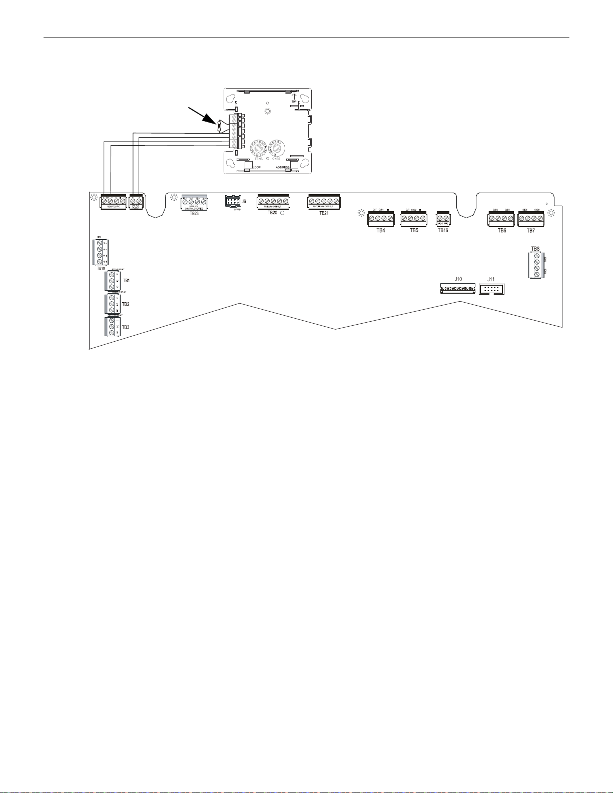
W-SYNC Wireless Synchronization Module Wiring
DISPLAY
24VDC Power
+ - + -
ECC-50/100
W-SYNC
3.9KΩ ELR
TB18
Sync
TB17
24VDC
Figure 5.2 W-SYNC Wiring to the ECC-50/100
synchronized output
5.2.2 ECC-50/100 Emergency Command Center
Wire the W-SYNC to the ECC-50/100 main circuit board as shown below.
50 SWIFT® Smart Wireless Integrated Fire Technology Manual — P/N LS10036-000FL-E:J 4/13/2020
Page 51

Wiring W-SYNC Wireless Synchronization Module
TB3
TB4
TB1
TB2
REF+ REF– + IN – IN
+ OUT
– IN
+ OUT
+ IN
– OUT
– OUT
SIGNAL 1
SIGNAL 2
BATT+ BATT–
A+
N/O
N/C
COMM
N/O
N/C
COMM
AC FAIL
TROUBLE
1L1 1L2 2L1 2L2
3L1 3L2
4L1 4L2A–
+
-
+ -
HPFF8/HPFF12
W-SYNC
3.9KΩ ELR
Figure 5.3 W-SYNC Wiring to HPFF8/HPFF12
C NC
24VDC Power
power supply
trouble input
synchronized
output
5.2.3 HPFF8/HPFF12 NAC Expander
When using the HPFF8 or HPFF12 to power the W-SNYC module, set the DIP switches on the HPFF8/HPFF12 as follows:
•SW1- OFF
•SW2- OFF
•SW3- OFF
•SW4- OFF
•SW5- ON
•SW6- OFF
Wire the W-SYNC to the HPFF8/12 as follows):
SWIFT® Smart Wireless Integrated Fire Technology Manual — P/N LS10036-000FL-E:J 4/13/2020 51
Page 52

6.1 Introduction
Figure 6.1 W-USB Adapter
!
The W-USB adapter is a software interface that can be connected to a PC (running SWIFT Tools) through a USB port. It communicates
with the RF devices using the same frequencies as the mesh protocol. This device is powered directly by the USB port.
The LED gives an indication of power and initialization status.
The W-USB adapter has an adjustable USB connector to facilitate connection by reducing the size when connected to a laptop/tablet.
Section 6: W-USB Adapter
Color Description
Red Device has power but is not initialized or the driver is missing.
Yellow Device is initialized and ready.
Blue Device is updating or failed to load properly. Complete the update or re-
power the device. If problems persist, contact technical support.
6.2 Agency Approvals
6.2.1 FCC
This device complies with part 15 of the FCC Rules. Operation is subject to the following two conditions:
1. This device may not cause harmful interference, and
2. This device must accept any interference received, including interference that may cause undesired operation.
FCC ID: PV3WFSADPT
WARNING: DO NOT MAKE CHANGES TO THE EQUIPMENT.
CHANGES OR MODIFICA TIONS NOT EXPRESSLY APPROVED BY THE MANUFACTURER COULD VOID THE USER’S
AUTHORITY TO OPERATE THE EQUIPMENT.
6.2.2 Federal Institute of Telecommunications
This device utilizes the Honeywell915 rev A radio module and complies with IFETEL standard(s).
IFT: RCPSYWU14-1829
52 SWIFT® Smart Wireless Integrated Fire Technology Manual — P/N LS10036-000FL-E:J 4/13/2020
Page 53

Specifications W-USB Adapter
Figure 6.2 Computer Management Screen
devcemanager6b.jpg
6.3 Specifications
6.3.1 Electrical Specifications
• Operating voltage: 4.3 VDC - 5.5 VDC (5VDC typical)
• Supply current: 25 mA - 85 mA (33 mA typical)
6.3.2 Serial Communication Specification
• USB standard 2.0
6.3.3 Mechanical Specifications
• USB Connector type A
• Length with connector closed: 3 in. (76.2 mm)
• Length with connector open: 3.8 in. (96.2 mm)
• Thickness on connector side: 0.5 in (13 mm)
• Thickness on antenna side: 0.3 in. (8.4 mm)
• Width: 1.2 in. (31.2 mm)
• Weight: 0.7 oz. (19.5 g)
6.3.4 Environmental Specifications
• Humidity: 10%RH - 93%RH, non-condensing
• Maximum operating temperature: 32°F - 122°F (0°C - 50°C)
• Storage temperature: 14°F - 140°F (-10°C - 60°C)
6.4 Driver Installation
NOTE: Install SWIFT Tools before attempting to install the driver.
To install a driver:
1. Insert the W-USB adapter into the PC. The W-USB ada pter is detected and is displayed in the Computer Management screen as a
SWIFT USB Communication Device.
SWIFT® Smart Wireless Integrated Fire Technology Manual — P/N LS10036-000FL-E:J 4/13/2020 53
Page 54

W-USB Adapter Driver Installation
Figure 6.3 Update Driver Software
devcemanager8.jpg
Figure 6.4 Browse Computer for Driver Software
devcemanager9.jpg
Figure 6.5 Browse Folder for Driver Software
devcemanager10.jpg
2. Right click on SWIFT USB Communication Device and select Update Driver Software.
3. Select the Browse my computer for driver software option.
4. The Browse dialog box appears. Click Browse. Navigate to the folder: C:\Program Files\Honeywell\Device Driver. Click Next.
54 SWIFT® Smart Wireless Integrated Fire Technology Manual — P/N LS10036-000FL-E:J 4/13/2020
Page 55
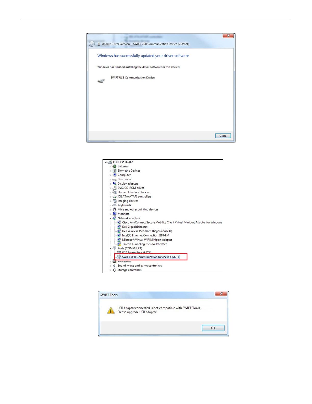
Driver Installation W-USB Adapter
Figure 6.6 Driver Software Update Confirmation
devcemanager11.jpg
Figure 6.7 New Communications Port
devcemanager7.jpg
devcemanager13.jpg
Figure 6.8 Incompatible W-USB Adapter Message
5. The confirmation message displays when the driver software is updated successfully.
The newly installed device will now display on the computer management screen under Ports.
If SWIFT Tools detects an incompatible W-USB adapter connected, it will prompt a message to update the W-USB adapter firmware.
If you get this error message, update the W-USB adapter through the Firmware Update feature in the Operations section of SWIFT
Tools.
SWIFT® Smart Wireless Integrated Fire Technology Manual — P/N LS10036-000FL-E:J 4/13/2020 55
Page 56

Notes
56 SWIFT® Smart Wireless Integrated Fire Technology Manual — P/N LS10036-000FL-E:J 4/13/2020
Page 57

A.1 Description
swifttools.wmf
Figure A.1 SWIFT Tools Screen
SWIFT Tools is a standalone desktop Windows® application. It is a configuration and maintenance tool for the gateway and devices of
the SWIFT Network. Site surveys, device configurations, and diagnostic functions are all part of SWIFT Tools. SWIFT Tools can be
installed on a PC or a laptop and communicates with the gateway and wireless devices through USB-based user interface. Connect the
W-USB to the computer to invoke the SWIFT Tools application. At any point, only one instance of SWIFT Tools can run on a laptop or
PC.
SWIFT Tools has the following utilities:
Site Survey view
Creating Mesh Network
Diagnostic view
SWIFT Tools works in a wireless environment with the gateway and devices within a range of approximately 20 feet.
SWIFT Tools is designed for systems running Microsoft Windows. Minimum system requirements are listed below.
Component Minimum Requirement
Operating System Windows 7 and Windows 8 (32 bit and 64 bit)
Hard Drive 20 GB hard drive space with minimum 1GB free space on hard disk.
RAM Minimum 512MB RAM
Processor speed 1GHz minimum (2.4 GHz recommended) Processor, 512K Cache
Regional Settings English (United States)
A.2 Launching SWIFT Tools
To launch SWIFT Tools,
1. Click Start, point to All Programs, click SWIFT Tool, and then SWIFT Tool. The following screen is displayed. Alternatively,
SWIFT Tools can be opened through a shortcut located on the desktop.
2. The SWIFT Tools screen is displayed. Create a new jobsite or open an existing one.
Appendix A: SWIFT Tools
Table A.1 System Requirements
A.2.1 Creating a New Jobsite
To create a new jobsite:
1. Click Create from the SWIFT Tools screen.
2. Enter the name of the new jobsite in the Jobsite Name field.
3. Enter the Location/Description if any, and click Create.
4. The Create Project dialog box opens. Navigate to the desired folder location where the project will be saved.
5. Click Save.
SWIFT® Smart Wireless Integrated Fire Technology Manual — P/N LS10036-000FL-E:J 4/13/2020 57
Page 58
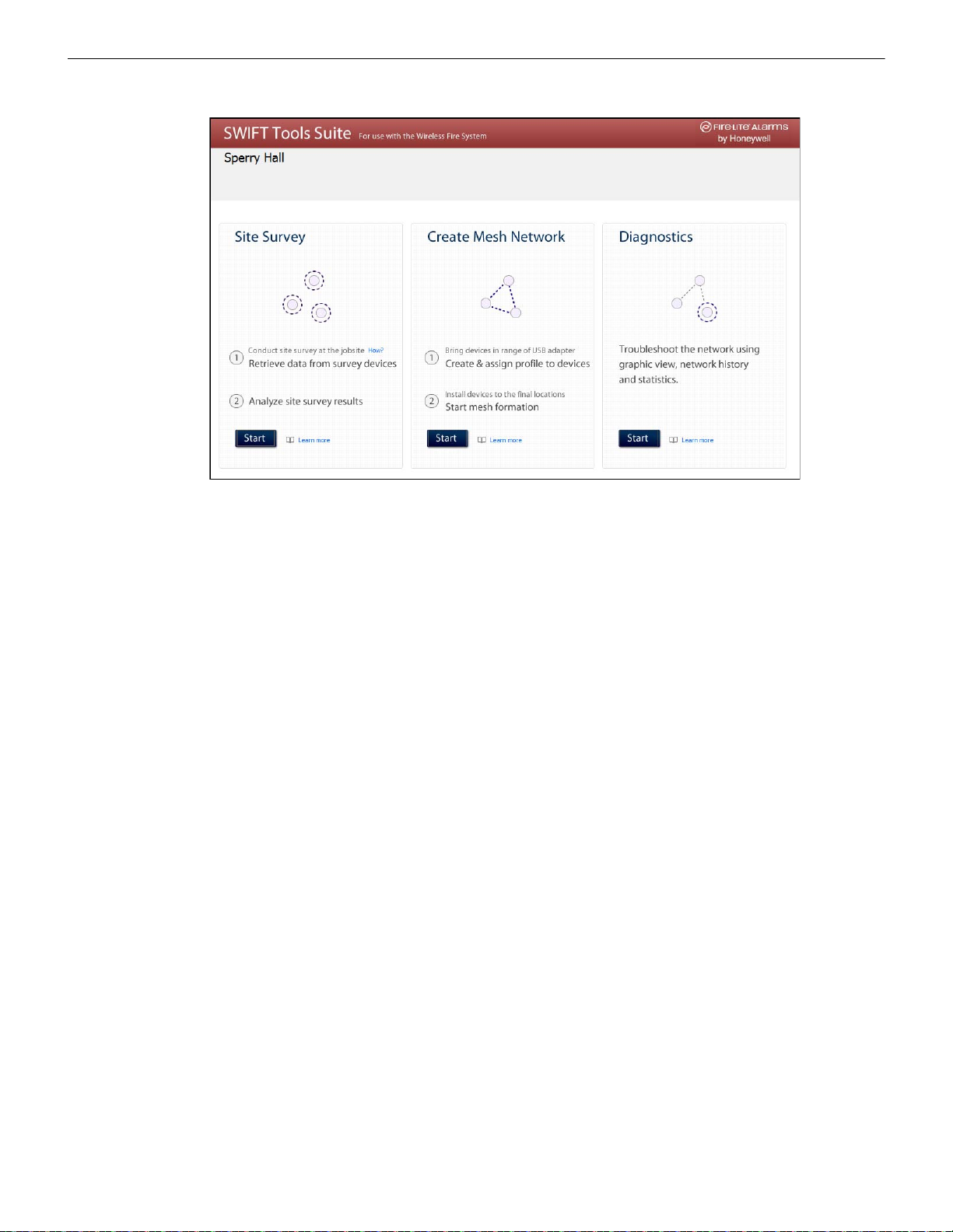
SWIFT Tools Connecting to the Gateway
homepage_fl.wmf
Figure A.2 Home Screen
The jobsite is created and the following screen is displayed. From this screen a site survey may be conducted, a mesh network may be
created, and troubleshooting may be performed. Click the Start button for the desired function.
For more information on performing a site survey , refer to Appendix B. To create a mesh network, see page 18. For help with diagnostics, refer to Appendix C.
A.2.2 Opening an Existing Jobsite
To open an existing jobsite:
1. Click Open from the SWIFT Tools screen.
2. Navigate to the folder containing the jobsite file. Select to highlight the file and click Open.
The existing jobsite is opened and Home screen is displayed. From this screen a site survey may be conducted, a mesh network may be
created, and diagnostics may be performed. Click the Start button for the desired function.
For more information on performing a site survey , refer to Appendix B. To create a mesh network, see page 18. For help with diagnos-
tics, refer to Appendix C.
A.3 Connecting to the Gateway
For security purposes, access to the gateway via SWIFT Tools requires the user be present inside the building and have physical access
to the gateway before they can establish a limited duration communication session that times out after a period of inactivity. To connect
to the gateway via SWIFT Tools, perform the following steps.
A.3.1 Accessing a Locked Gateway
1. Select the desired gateway.
2. Enter a valid password into SWIFT Tools.
3. SWIFT Tools will show a 120 second timer.
4. Use a magnet to activate either of the two sensors on the gateway within the 120 second time-frame. The LEDs will turn on steady
yellow. The gateway LEDs will blink green and then resume normal operation.
5. Communication between the T ools and the gateway is now available. The system has a 30 minute inactivity timer. If no activity is
detected within 30 minutes, the connection between the Tools and gateway will close. The user will need to repeat steps 1-3 to
reconnect.
A.3.2 Creating a New Password for a Gateway
1. Select the desired gateway.
2. Assign a valid password to SWIFT Tools.
3. SWIFT Tools will show a 120 second timer.
4. Use a magnet to activate either of the two sensors on the gateway within the 120 second timeframe.The gateway LEDs will turn on
steady yellow.
5. The LED resumes to normal operation once magnet is activated or the wait for Magnet Activati on tim es o ut. Communication
between the Tools and the gateway is now available till the user accesses. The system has a 30 minutes inactivity timer. If no
activity is detected within 30 minutes, the connection between the Tools and gateway will close. The user will need to repeat steps
1-3 to reconnect.
58 SWIFT® Smart Wireless Integrated Fire Technology Manual — P/N LS10036-000FL-E:J 4/13/2020
Page 59

Notes
SWIFT® Smart Wireless Integrated Fire Technology Manual — P/N LS10036-000FL-E:J 4/13/2020 59
Page 60

A site survey is recommended to assess and qualify the site prior to installing a SWIFT network. The site survey consists of a link quality
test and RF scan test. After both tests are completed, the results of the site survey can be obtained using SWIFT Tools. The information
provided by SWIFT Tools is used for site qualification, maximum device spacing identification, and configuring the network. This helps
to improve the reliability and performance of the wireless network in the wireless fire alarm system.
B.1 Conduct a Site Survey
B.1.1 Link Quality Test
A link quality test is a quick and repeatable test that pr ovides immediate feedback on device connectivity. The link quality test sends data
from one device to another to test for data loss and measure the signal strength. In a link test, the device addresses are set in the range of
001 to 150. A minimum of two devices are needed to conduct a link quality test.
A link test is conducted between two or more devices. The link test starts when a device that is in the “pending site survey” state has its
tamper condition cleared. The device will send a burst of data to the next address lower than its own address. The lower addressed device
will automatically return the link quality test resul ts for di splay using the device LEDs. For example, clearing the tamper condition on a
detector set to address 2 (D002) will make the detector enter the link quality test. D002 will send a burst of data to a device at address
001 (either detector or module). The device at address 001 will measure the signal strength and count the data received in the burst and
return the information to D002. The results of the test will be displayed at D002. The test can be repeated by tampering D002 to return it
to the “pending site survey” mode and then clearing the tamper.
Basic Requirements of a Link Quality Test
To conduct a link test:
two or more devices (detectors) are required.
devices must be in factory default state. The LEDs on the device will blink single or double red to confirm it is in the factory
default state. Refer to Section 4.5.3 on page 45 for more information on setting the device to factory default state.
device addresses can bet set in the range of 1 to 150.
Conduct a Link Quality Test
To con duct a link quality test:
1. Remove the batteries from the devices that will be used for the site survey and set the SLC address. To set an SLC address, use a
flathead screwdriver to adjust the rotary switches on the devi ce .
1. For the first device used in a site survey, set the SLC address to 001.
2. For each subsequent device, use the next highest SLC address (up to address 150). For example, the first device was set to 001,
set the second device to 002, and the third device to 003, etc.
2. Bring the first device (001) to the first location to conduct the test.
3. Insert one battery into the device. Inserting more than one battery deters the device from entering the site survey mode. The device
is ready for site survey mode if the LED blinks yellow every 5 seconds.
4. Clear the tamper condition to proceed with the test. To clear the tamper condition on a detector, insert the detector into the base and
twist to lock the detector completely into the base. To clear the tamper condition on a module, attach the faceplate to the module.
When the tamper is cleared, the LEDs on the device starts blinking yellow every ½ second for approximately 20 seconds. The
results appear in approximately 20 seconds and the LEDs on the first device change to solid red. This is due to the absence of a
lower-addressed device with which to form a pair. This result is expe cte d from the 1 st device when a link quality test is performed.
5. Bring the second device (002) to the second location and insert one battery into the device. The device is ready for site survey mode
if the LED blinks yellow every 5 seconds.
6. Clear the tamper condition to proceed with the test. To clear the tamper condition on a detector, insert the detector into the base and
twist to lock the detector completely into the base. To clear the tamper condition on a module, attach th e faceplate to the module.
When the tamper is cleared, the LEDs on the device starts blinking yellow every 1/2 second for approximately 20 seconds. The
results appear in approximately 20 seconds.
7. Repeat for subsequence devices.
8. The device will conduct a link test to the next lowest address; in this case device 001. The result of the link test from 002 to 001 is
displayed by the LEDs on device 002. Refer to Table B.1 below.
9. Once the link test is complete between 002 and 001, continue for address 003, 004, etc. for all devices that will be used in the site
survey. This test may be repeated any number of times. For devices addr essed to 101 or higher, the test must be repeated, if desired,
within five minutes of the last concluded test or the devices will start an RF scan test.
Appendix B: Site Survey
60 SWIFT® Smart Wireless Integrated Fire Technology Manual — P/N LS10036-000FL-E:J 4/13/2020
Page 61

Conduct a Site Survey Site Survey
Results of a Link Quality Test
The following table explains the LED patterns before and during a link quality test.
State Pattern LED Results & Description
Site survey pending Double blink every 5 seconds Red Device is tampered, ready and waiting to start a site survey link
Link quality test in progress Single blink every ½ seconds Yellow Transmission of data to another device.
Link quality test complete On steady Red Failure - no data received
Link quality test complete Single blink every 5 seconds Red Poor - partial data received or signal strength measured lower
Link quality test complete 2 blinks every 5 seconds Green Good - all data received at a signal strength acceptable for a
Link quality test complete 3 blinks every 5 seconds Green Great - all data received at a signal strength acceptable for a
Link quality test complete 4 blinks every 5 seconds Green Excellent - all data received at a signal strength acceptable for a
quality test
than the acceptable limit for a primary or secondary link (-81dBm
or lower)
secondary link but not for a primary link (-66dBm to -80dBm)
secondary link and marginally acceptable for a primary link
(-51dBm to -65dBm)
primary link (-50dBm or better)
Table B.1 LED Patterns of Link Quality Test Results
The LED pattern for a link quality test will continue to be displayed until the device is tampered or the batteries die for a device that is
addressed 100 or lower. For devices addressed 101 to 150, the result will be displayed until the device starts the RF Scan.
To repeat the link quality test, toggle the tamper state. To toggle the tamper state on a detector, twist the detector in the base counterclockwise as if removing the detector from the base, then twist it back in clockwise to lock it in. T o toggle the tamper state on a module,
remove the faceplate and then reconnect it. Once the device is tampered, it will return to the pending site sur vey state. Once the tamper is
cleared, the link quality test will be restarted. Only the results for the last link quality test are retained .
After a Link Quality Test
Retrieve the link quality test results for devices 001-100. To retrieve the site survey results, refer to the topicB.1.3, "Retrieving Site Survey Results"at the end of this section. For devices 101-150, wait to retrieve the link quality results until the device starts an RF Scan test.
B.1.2 RF Scan Test
A Radio Frequency scan test is conducted to assess and measure the background noise and interference from other wireless systems if
any, in the site. The RF Scan test can be conducted individually or following the link quality test. An RF Scan test will be conducted for
any device with an SLC address set between 101 and 150 at the end of a Link Quality Test.
Conduct an RF Scan Test
To conduct an RF scan test, follow the same procedure for a link quality test. However, the device addresses for an RF scan test must
start at 101 and have the subsequent devices address set as 102, 103, etc. Each device will conduct the link quality test as described
above, then transition to the RF scan test 5 minutes after the last link quality test is performed to or from that device.
If several devices are being tested, it is possible that some devices will start and complete the lin k test and progre s s to the RF scan test
while other devices are finishing the link quality test. The RF Scan test may take up to 70 minutes. The time remaining and the test status
are displayed at the device using the LEDs. The LED patterns are shown below.
Status of an RF Scan Test
State Pattern LED Status
In Progress- 70 minutes remaining 7 short blinks every 30 seconds
In Progress- 60 minutes remaining 6 short blinks every 30 seconds
In Progress- 50 minutes remaining 5 short blinks every 30 seconds
In Progress- 10 minutes remaining 1 short blink every 30 seconds
RF Scan Test Complete On Steady
Table B.2 RF Scan Test Status - LED Pattern
Red Bad
Green Good
Red Bad
Green Good
Red Bad
Green Good
Red Bad
Green Good
Red Bad
Green Good
SWIFT® Smart Wireless Integrated Fire Technology Manual — P/N LS10036-000FL-E:J 4/13/2020 61
Page 62

Site Survey Conduct a Site Survey
!
B.1.3 Retrieving Site Survey Results
To retrieve the site survey results:
1. Return the device to “Pending Site Survey” or “Factory Default” mode. This is done by tampering devices that have completed a
link quality test or by rebooting devices that have completed an RF scan test.
CAUTION: SITE SURVEY RESULTS WILL BE REPLACED
DO NOT CLEAR THE TAMPER ON A DEVICE THAT IS IN THE “PENDING SITE SURVEY” STATE OR THE EXISTING
RESULTS WILL BE REPLACED.
2. Plug the W -USB adapter into the laptop/PC where SWIFT Tools has been installed.
3. Bring the devices within a range of approximately 20 feet from the W-USB adapter connected to the laptop/PC.
4. Log into SWIFT Tools and retrieve the data.
62 SWIFT® Smart Wireless Integrated Fire Technology Manual — P/N LS10036-000FL-E:J 4/13/2020
Page 63

Appendix C: Troubleshooting and Testing
C.1 Troubleshooting
Problem Description Action
Class A fault condition Device has a single parent connection, and is
missing the redundant class A connection.
Jamming Jamming occurs when a device is overloaded
with an interfering RF signal and is unable to
process incoming messages, but is able to report
the condition to its parents.
Low battery One or more of the four batteries are
Duplicate address/
Illegal address
Mesh formation does
not find all devices
Mesh restructuring does
not end
Devices drop during
operation
Max gateway trouble
reported
Device does not rejoin
the mesh after battery
replacement
Low battery trouble
reported after battery
replacement
missing/dead and/or the device has a minimum
of one week of operation remaining.
Two or more wireless devices on the same mesh
network that are set to the same address report a
duplicate address trouble. An address set to zero
will report an illegal address.
A device does not connect to the gateway/mesh
network
The gateway/mesh network appears to be stuck
in mesh restructuring
A device drop event is indicated in history. Device drop is the predecessor to a No Answer/Invalid reply trouble.
The number of Honeywell SWIFT systems that
can co-exist in range of each other has been
exceeded.
Device is an invalid reply/no answer after
replacing the batteries.
Low battery trouble is still indicated after
replacement.
If a suitable parent is available, the background mesh restructuring
routine should self-heal the network. If the network does not self-heal
after ten minutes, reduce spacing between devices or utilize SWIFT
Tools for suggested repeater placement to add stronger parents.
Activate mesh formation to trigger a mesh restructuring routine to reevaluate the trouble condition after taking action.
A jammed device will automatically remove itself from the mesh
network after reporting the jamming. The device will attempt to selfheal and recover into the network. Identify any possible sources of the
jamming signal and see if the spacing from the device to the jamming
source can be increased to an acceptable range. A site survey RF
scan test can be used to categorize the jamming signal.
To clear the low battery event, tamper the device and replace all four
batteries. When a device is tampered, it drops out of the mesh
network and attempts to rejoin as soon as the batteries are replaced
and the tamper event is cleared. Once a low battery trouble is
indicated there is a minimum of one week of operation before the
device is non-functional.
Change the address of the device(s) to avoid duplication and error.
Verify the device has a profile. Verify that the profile matches the
profile in the gateway. Two different profiles may use the same mesh
ID. Remove and re-profile the device to guarantee the correct profile.
Verify the device is powered and the tamper condition is cleared.
Check to ensure the tamper magnet has not become dislodged.
Check the device spacing and the range from the device to the mesh.
A site survey link test can be used to verify connectivity from one
location to another.
Use SWIFT Tools or panel history to investigate for the presence of
interference such as Walkie talkie/ RFID reader or unstable devices
(dropping and joining). Interference such as Walkie talkie/ RFID
reader will prohibit restructuring from fully executing. Devices joining a
mesh will delay the restructuring event.
Inspect the area for any changes to the environment that could block
radio communication. Use a site survey RF Scan to check for any
interference and use a site survey link test to check the connectivity
from the device to its closest neighbor.
Use the network statistics provided by SWIFT Tools to identify the
interfering networks and the nature of the fault. The networks will be
listed by a unique number; this is not the serial number of the
gateway. One or more of the systems will need to be powered down to
clear the fault. Where possible, maximize the number of devices on a
mesh network to reduce the number of total mesh networks; i.e. use
one mesh network with 50 devices instead of two mesh networks with
25 each. Restructure the layout of the mesh networks to group
devices and the gateway to avoid overlap. It may take 36 hours for the
fault to clear. This can be expedited by toggling the state of mesh
formation.
Verify the tamper condition is cleared. Use mesh formation to have the
device rejoin the mesh network. Low battery and tamper are both
latching conditions. Ensure a reset has been initiated to
events.
Use the network statistics provided in SWIFT Tools to see the battery
voltage measured for each individual battery. Verify that each battery
is present and at a suitable voltage level. The low battery trouble is a
latching trouble, ensure a reset has been initiated since the
replacement.
clear those
SWIFT® Smart Wireless Integrated Fire Technology Manual — P/N LS10036-000FL-E:J 4/13/2020 63
Page 64

Troubleshooting and Testing Testing the Gateway and Devices
Problem Description Action
Site survey does not
find a link
SWIFT Tools does not
import site survey data
SWIFT Tools says
device/gateway is out of
range
Scan does not find any
devices
Site survey devices are
not displayed in the
communicator of
SWIFT Tools.
FACP reports invalid
reply/No Answer for the
gateway
FACP reports invalid
reply/No answer for the
wireless detectors
FACP reports invalid
reply/No answer for the
wireless modules
Device does not receive
a profile
Application download
fails
Device is in bootloader Device/Gateway is indicating the LED pattern for
Type Trouble A T y pe T rouble has occurred on AV device points
Key Bus trouble The ANN-80 has lost connection with the display
Solid red results for the link test Verify the addresses of the devices used during the test. The lower
addressed device must complete its link test before the device at the
next higher address starts the link test. Verify the devices are in range
of each other.
Selecting the device in the communicator in
SWIFT Tools does not have an effect
Device or gateway is not communicating to
SWIFT Tools
All devices are out of range Verify at least one device is in range of SWIFT Tools, the W-USB
Verify the device is in the pending site survey mode or factory default
Gateway is not communicating with the panel Verify the loop is running in LiteSpeedfor detectors and modules.
FACP does not recognize the detectors Verify the loop is running in LiteSpeedfor detectors. Verify using
FACP does not recognize the modules Verify the loop is running in LiteSpeed for the modules. Verify using
A profile request has been initiated but timed out
before receiving a profile
SWIFT Tools failed to finish a download Verify the number of devices in range of the W-USB adapter during
bootloader and it is indicated as being in
bootloader in the communicator of SWIFT Tools.
previously in a normal state after power is
reapplied to the panel.
driver.
The device does not have any site survey results to be imported. It
has not found a link during the link test and/or it has not collected any
data for an RF Scan.
Verify the device or gateway is powered on and in a state that
supports SWIFT Tools communication. For instance, a device in the
mesh network does not communicate to SWIFT Tools. It
communicates to the gateway. A device that has completed a site
survey does not communicate to SWIFT Tools until it returns to the
pending site survey state or factory default state. Move the W-USB
adapter in range of gateway/devices.
adapter is connected, and the scan is on. SWIFT Tools processes the
messages faster with multiple devices in range. If only one device is in
range it can take up to 1 minute for the scan to detect the device.
mode. The device will not communicate with SWIFT Tools while it is in
site survey mode.
Verify the gateway is set to a valid address.
SWIFT Tools that the detectors are part of the mesh network.
SWIFT Tools that the modules are part of the mesh network.
Ensure the gateway or distributor is still in distributor mode. Ensure
the device is in range of the gateway or distributor. If there are multiple
devices in range, the might be interfering with the profile transfer.
Move the distributor and device to a different area or shut down the
peripheral devices.
the download does not exceed the recommended limit of 10 devices.
Verify the device is in range and powered on during the download
process.
The device failed to load or initialize the application. Reboot the
device. If it is still in bootloader, the application will need to be updated
using SWIFT Tools. If problem persists, contact technical support.
Remove and reapply power to the Gateway by removing the SLC
connection or 24V supply wiring.
Check the connection between the ANN-80 and the display driver and
reboot the display driver..
C.2 Testing the Gateway and Devices
The gateway must be tested after installation and be part of a periodic maintenance program. The testing methods must satisfy the
Authority Having Jurisdiction (AHJ). The gateway provides optimum performance when tested and maintained in compliance with
NFPA 72 ordinances.
C.2.1 Testing LED Indicators
For more information on LED indicators, refer to Appendix D, “LED Indicators”, on page 67.
C.3 Testing the Wireless Network
Using the SWIFT Tools application, users can:
64 SWIFT® Smart Wireless Integrated Fire Technology Manual — P/N LS10036-000FL-E:J 4/13/2020
Page 65

Testing the Wireless Network Troubleshooting and Testing
• Diagnose and troubleshoot the wireless network and connectivity of the devices.
• Monitor the wireless network topology, quality of the communication links between the devices, live and historical event reports for
troubleshooting purposes.
• View the parent-child relationship and the signal strength between the two devices, and identify the device that has lost the
communication link with the wireless network.
In addition, SWIFT Tools:
• Communicates with the gateway to retrieve live information about the connectivity and status of the devices.
• Stores the wireless network data such as network map, parent-child information, device information, history events, and network
statistics.
The SWIFT Tools application allows retrieval of the following information for diagnosing and troubleshooting purposes.
• Network Topology
• History of Events
• Network Snapshots
• Network Statistics
• Device Attributes
C.3.1 Network Topology
Parent-Child Devices
The parent-child relationship between the devices in the wireless network is displayed using the directional arrows.
Orphan Devices
A device that is not linked with any other device in the wireless topology is an orphan device. The device is represented as an orphan
device due to one of the following reasons:
• The device was originally a part of the wireless network and was dropped.
• When the network topology was retrieved, the device detail was not retrieved.
• The network connections are saturated and parent-child connection with the device is not established.
Class A Compliance
Each device must comply with Class A guidelines. Every device must have two parent devices to be compliant with the Class A guidelines.
NOTE: The device image in SWIFT Tools is altered to depict that it does not meet the required guidelines.
NOTE: Class A guidelines are not applicable to the gateway.
Selecting a device from the graphical representation and clicking either left or right allows you to view the following details. The Network Topology window allows you to click either left or right on any connected or orphan device.
C.3.2 History Events
History events of the wireless network can be retrieved and viewed using SWIFT Tools for troubleshooting purposes. This report provides information on when the device gets connected with the wireless network, mode change, and slot change details.
C.3.3 Network Snapshots
Network snapshots can be retrieved and viewed using SWIFT Tools for troubleshooting purposes. The network snapshot helps to analyze how the wireless network is functioning over a period of time.
C.3.4 Network Statistics
Network statistics of the wireless network can be retrieved and viewed using SWIFT Tools for troubleshooting purposes. The network
statistics provide information on the attributes and RSSI of a device. The attributes provide information on the retransmission count and
device re-join events. The retransmission count is the number of times a device retransmits the wireless signal. The device re-join events
is the number of times the devices get disconnected from the wireless network and get connected with the wireless network. The RSSI of
a device displays the parent-child relationship between the devices.
C.3.5 Device Attributes
Device attributes can be retrieved and viewed using SWIFT Tools for troubleshooting purposes. The attributes of a device such as low
indication, removal indication, level, tamper fault, and others are retrieved.
SWIFT® Smart Wireless Integrated Fire Technology Manual — P/N LS10036-000FL-E:J 4/13/2020 65
Page 66

Notes
66 SWIFT® Smart Wireless Integrated Fire Technology Manual — P/N LS10036-000FL-E:J 4/13/2020
Page 67
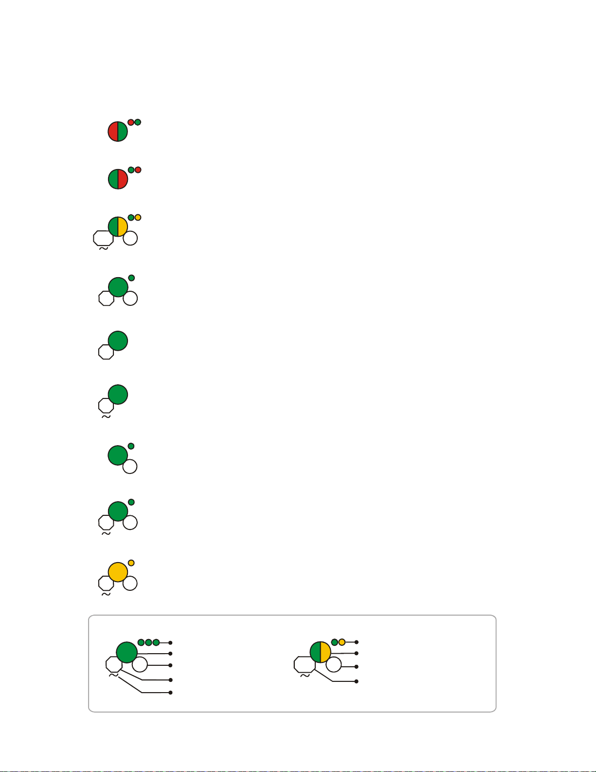
Appendix D: LED Indicators
LED Pattern Condition Action Required
Bootloader
normal
Bootloader
Firmware update
Mesh formation
Profile removed
Profile accepted
Normal mode/
background mesh
restructuring
Rescue mode
Device is ready to update
New application code is being downloaded
Gateway is forming the mesh and looking for
devices that are not in the mesh
Wait until all devices join the mesh
and then terminate mesh formation
Gateway has returned to the factory default
state
Gateway is now profile assigned
Normal operation of the gateway
Gateway and the mesh network are searching
for any device that is not in the mesh network
with the same profile
Legend
Number of blinks
LED color
Interval between blink patterns
Duration of LED state
Indicates value is approximate
Two blinks in this pattern
First blink is green, Second is yellow
7 seconds between blink patterns
Will transition to next state after
approximately 20 minutes
Example:
All units are in seconds. “M” indicates Minute. “V” indicates Variable.
ledgate1_4.0.wmf
6
20
M
1
5
10
18
12
3
M
Solid
7
20
M
10
1
Profile assigned
Gateway is starting up with a profile
Mesh update in
progress/Mesh
update -parent node
Gateway is updating the mesh/Parent nodes
are updating child nodes
4
M
Solid
Activate both magnetic sensors
simultaneously within 10 seconds to
remove a profile
Figure D.1 Gateway LED Patterns
The LED indicator patterns for the wireless gateway, display driver, and wireless devices are shown in the tables below.
SWIFT® Smart Wireless Integrated Fire Technology Manual — P/N LS10036-000FL-E:J 4/13/2020 67
Page 68

18
4
10
1
10
7
20
M
LED Pattern Condition Action Required
Normal mode
Address zero
trouble
Factory default
Waiting for a profile
The gateway is in the mesh and may be in trouble Refer to the FACP to identify the
trouble and possible solution
The gateway address is set to zero
Gateway is starting up without a profile
Gateway is in factory default mode
Legend
Number of blinks
LED color
Interval between blink patterns
Duration of LED state
Indicates value is approximate
Two blinks in this pattern
First blink is green, Second is yellow
7 seconds between blink patterns
Will transition to next state after
approximately 20 minutes
Example:
ledgate2_4.0.wmf
Ensure all devices in the mesh
have a valid address
Use SWIFT Tools to assign a profile
Figure D.2 Gateway LED Patterns (Continued)
Rescue mode
Gateway and the mesh are searching for any
device that is not in the mesh network with the
same profile. The gateway may be in trouble
12
3
M
Normal mode/
background mesh
restructuring
Rescue mode
Gateway is in the mesh
Gateway and the mesh network are searching for
any device that is not in the mesh network with the
same profile
18
12
3
M
Mesh update ready
Received command from SWIFT Tools to start
a firmware update
Solid
V
All units are in seconds. “M” indicates Minute. “V” indicates Variable.
5
M
6
1st mesh
restructuring
Mesh is formed and initializing Ensure all devices in the mesh have a
valid address
68 SWIFT® Smart Wireless Integrated Fire Technology Manual — P/N LS10036-000FL-E:J 4/13/2020
Page 69

LED Pattern Condition Action Required
Bootloader
normal
Slot request
rejected
Mesh formation
Bootloader
firmware update
Profile removed
Profile received
Rescue mode
Normal mode
Self test fail
Display driver is ready to update Use SWIFT Tools to initiate
download
Display driver is not permitted
into the mesh
Display driver is in the mesh and
looking for devices that are not in
the mesh
New application code is being
downloaded
Display driver has returned to the
factory default state
Display driver is now profile
assigned
Display driver is functioning as
normal and searching for lost
devices
Display driver is in the mesh
Display driver has failed internal self
diagnostics
Legend
Number of blinks
LED color
Interval between blink patterns
Duration of LED state
Indicates value is approximate
Two blinks in this pattern
First blink is green. Second is yellow
7 seconds between blink patterns
Will transition to next state after
approximately 20 minutes
Example:
ledlcd1_4.0.wmf
Confirm device count and
software version
Restart the device. If the
problem persists, contact
technical support
8
6
20
M
1
5
10
3
M
12
Solid
Solid
18
20
M
7
Figure D.3 Display Driver LED Patterns
Alarm/Active state
Display driver has been activated
All units are in seconds. “M” indicates Minute. “V” indicates Variable.
Profile removal
timeout started
Remove the profile from the hall
sensor-activated display driver
within 60 minutes
3
V
3
SWIFT® Smart Wireless Integrated Fire Technology Manual — P/N LS10036-000FL-E:J 4/13/2020 69
Page 70
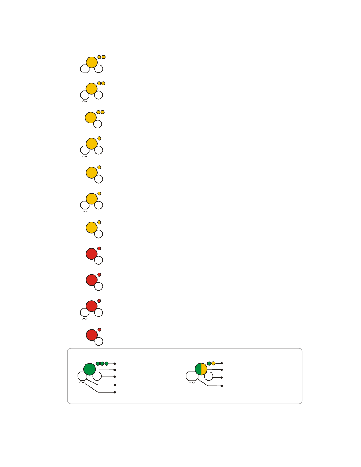
LED Pattern Condition Action Required
Searching for mesh
(in rescue mode)
Searching for mesh
(in formation mode)
1st mesh
restructuring
Normal mode
Waiting for profile
Profile is assigned and display
driver is searching for the mesh
Ensure the mesh is in rescue
mode or wait for timeout to
search mesh in formation mode
Profile is assigned and display
driver is searching for the mesh.
Mesh is formed and initializing
Display driver is in the mesh and
may be in a trouble condition
Display driver is in the factory
default state.
Legend
Number of blinks
LED color
Interval between blink patterns
Duration of LED state
Indicates value is approximate
Two blinks in this pattern
First blink is green. Second is yellow
7 seconds between blink patterns
Will transition to next state after
approximately 20 minutes
Example:
ledlcd2_4.0.wmf
Ensure the mesh is in
formation mode
Figure D.4 Display Driver LED Patterns (Continued)
Refer to the FACP to identify the
trouble and possible resolution
Use SWIFT Tools to assign a
profile or activate magnetic
sensor to search for a profile.
90
3
25
5
M
6
18
10
7
20
M
Rescue mode
Display driver is in the mesh and
looking for lost devices. The
display driver may be in trouble
12
3
M
Alarm/Active state
3
Display driver has been activated
Refer to the FACP to identify the
trouble and possible resolution
Normal mode Display driver is in the mesh
18
Rescue mode
Display driver is in the mesh and
looking for lost devices
12
3
M
Alarm/Active state
3
Display driver has been activated
All units are in seconds. “M” indicates Minute. “V” indicates Variable.
Profile assigned,
pending magnetic
sensor activations
Display driver is starting up with a
profile
Activate both magnetic sensors
simultaneously within 10
seconds to remove a profile
10
1
70 SWIFT® Smart Wireless Integrated Fire Technology Manual — P/N LS10036-000FL-E:J 4/13/2020
Page 71
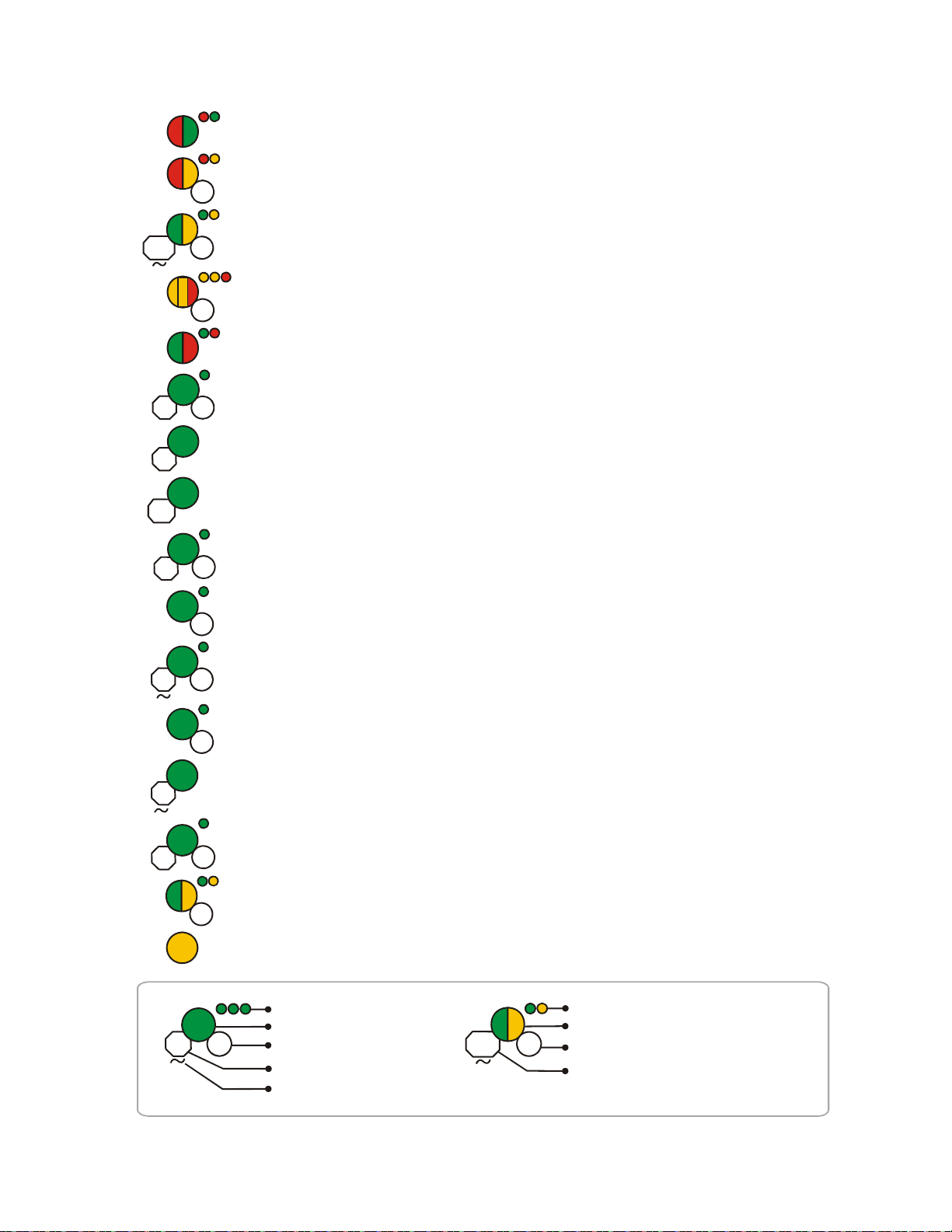
LED Pattern Condition Action Required
Bootloader normal
Slot request rejected
Mesh forming
Sustained tamper
Bootloader firmware
update
Profile received
Battery check: all
batteries are fresh
Profile removed
Device is ready to update
Device is not permitted into the mesh
Device is part of the mesh and looking
for devices that are not in the mesh
New application code is being
downloaded
Device now has a profile assigned
Maximum battery life remaining in
device
Device has returned to the factory
default mode
Legend
Number of blinks
LED color
Interval between blink patterns
Duration of LED state
Indicates value is approximate
Two blinks in this pattern
First blink is green. Second is yellow
7 seconds between blink patterns
Will transition to next state after
approximately 20 minutes
Example:
Confirm device count and software
version
Device is tampered
Solid
Solid
8
6
20
M
15
5
1
10
2.5
Ensure detector is seated in the base
and the module has the faceplate on
123
M
Rescue mode
Device is in the mesh and
looking for lost devices
Normal mode or
tested walktest
Device is in the mesh or it has
been tested in a walktest.
7
20
M
Figure D.5 Device LED Patterns
Use SWIFT Tools to initiate download
Self test fail Device has failed internal self
diagnostics.
Restart the device. If problem
persists, contact technical support
Solid
18
Mesh update -parent
node
The gateway is updating parent nodes
in the mesh
4
M
Solid
V
10
Mesh update idle
Devices that are included in mesh
update are complete and waiting for
the whole mesh to finish updating
Mesh updating
Green and yellow flicker pattern
indicates that data packets are being
received by the device.
0
leddev1_4.0.wmf
All units are in seconds. “M” indicates Minute. “V” indicates Variable.
3
V
Profile removal timeout
started
Remove the profile from the
tampered/hall sensor activated
device within 60 minutes
Active/Alarm state Device has been activated
3
SWIFT® Smart Wireless Integrated Fire Technology Manual — P/N LS10036-000FL-E:J 4/13/2020 71
Page 72

LED Pattern Condition Action Required
Legend
Number of blinks
LED color
Interval between blink patterns
Duration of LED state
Indicates value is approximate
Two blinks in this pattern
First blink is green. Second is yellow
7 seconds between blink patterns
Will transition to next state after
approximately 20 minutes
Example:
leddev2_4.0.wmf
7
20
M
Figure D.6 Device LED Patterns (Continued)
Battery Check: all
batteries present
Searching for mesh
(in rescue mode)
1st mesh
restructuring
Normal mode
Searching for mesh
(in formation mode)
Minimum of 6 months battery life
remaining
Mesh is formed and initializing
Device is in the mesh and may be in
trouble
Profile is assigned and device is
searching for the mesh
Profile is assigned and device is
searching for the mesh.
Tamper entry Device has just been tampered
Ensure the mesh is in rescue mode or wait for
timeout to search mesh in formation mode.
Discovered mesh Device discovered the mesh
Solid
2.5
90
3
Ensure the mesh is in formation mode
25
6
5
M
Refer to the FACP to identify the trouble and
possible resolution.
18
4
Ensure detector is seated in the base and the
module has a faceplate
Solid
6
Solid
Waiting for a profile
Pending site survey
Active/Alarm state
Battery Check:
weak
Device is in factory default mode
Device is in factory default mode and is
ready to enter site survey mode
Less than 6 months battery life left or
not all 4 batteries are present
Device has been activated
Use SWIFT Tools to assign a profile.
Ensure all 4 batteries are present or replace the
batteries
Clear the tamper condition within
1 minute to enter site survey mode
10
5
Solid
2.5
3
18
12
5
M
Normal mode Device is in the mesh
Rescue mode Device is in the mesh and looking for
lost devices
Rescue mode
Device is in the mesh, looking for lost
devices, and may be in trouble
12
3
M
Refer to the panel to identify the trouble and
possible solution
All units are in seconds. “M” indicates Minute. “V” indicates Variable.
3
Active/Alarm state Device has been activated
Replace batteries
3
Low battery cut-off Device is functioning
72 SWIFT® Smart Wireless Integrated Fire Technology Manual — P/N LS10036-000FL-E:J 4/13/2020
Page 73

Notes
SWIFT® Smart Wireless Integrated Fire Technology Manual — P/N LS10036-000FL-E:J 4/13/2020 73
Page 74
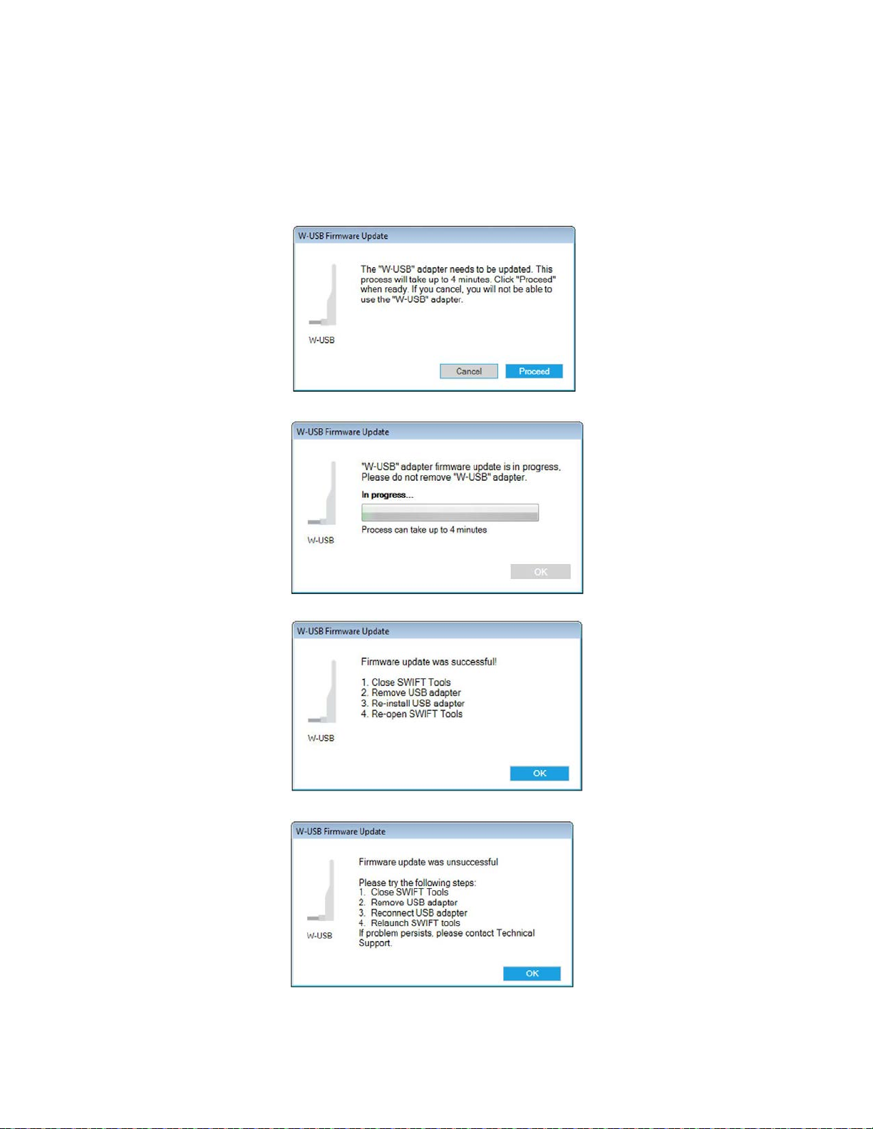
Appendix E: Firmware Upgrade/Downgrade Instructions
To ensure proper system operation, this product must be tested in accordance with NFPA 72 after any programming operation or change in
site-specific software.
E.1 W-USB Adapter Upgrade Procedure
The following procedure provides firmware upgrade instructions for the W-USB adapter. Ensure the latest version of SWIFT Tools is
installed. SWIFT Tools and firmware can be downloaded from www.firelite.com. There are multiple .bin files with the zip file. S ave the
files to a folder. The W-USB adapter wi ll auto-update if the SWIFT Tools and W-USB adapter versions are incompatible.
1. Insert the W-USB adapter into the PC and launch SWIFT Tools. A pop-up message confirming the W-USB adapter update will be
displayed.
2. Click Proceed. The following screen will display.
3. If the USB update is successful, the following screen will display.
4. If the USB update fails, the following screen will display.
74 SWIFT® Smart Wireless Integrated Fire Technology Manual — P/N LS10036-000FL-E:J 4/13/2020
Page 75
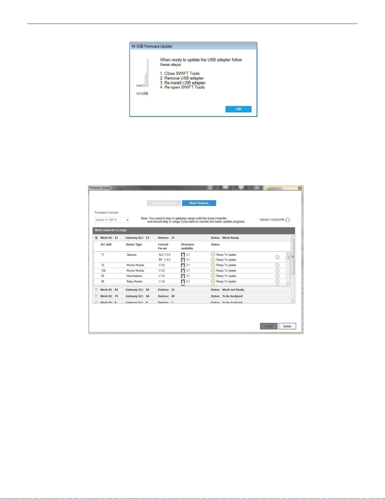
Mesh Network Firmware Upgrade/Downgrade Procedure Firmware Upgrade/Downgrade Instructions
5. If the USB update is declined by clicking Cancel at step 1, a re-update procedure will display.
E.2 Mesh Network Firmware Upgrade/Downgrade Procedure
The following procedure provides firmware upgrade and download instructions for the gateway mesh. Ensure the latest version of
SWIFT Tools is installed. SWIFT Tools and firmware can be downloaded from www.firelite.com. There are multiple .bin files with the
zip file. Save the files to a folder.
1. Launch SWIFT Tools and navigate to the home screen and select either Site Survey, Create Mesh Network, or Diagnostics.
2. Ensure the gateway is in range of the W-USB adapter and the PC running SWIFT Tools.
3. Click on the Operations menu and select Firmware Update.
4. Select the Mesh Network tab from the displayed screen. The Firmware Update screen is displayed.
5. Select the Service Pack from the Firmware Version drop-down box or click Choose File and then browse for the service pack zip
file from your local drive and click OK.
6. Select the respective gateway and follow the on-screen instructions and wait until the mesh feasibili ty che ck fini shes.
7. Click Update. As the mesh update progresses, the status bar will update.
E.3 Device, Gateway, and Display Driver Firmware Upgrade/Downgrade Procedure
The following procedure provides firmware upgrade and download instructions for the wireless devices, gateway, and display driver.
Ensure the latest version of SWIFT Tools is installed. SWIFT Tools and firmware can be downloaded from www.firelite.com. T her e are
multiple .bin files with the zip file. Save the files to a folder.
1. Launch SWIFT Tools and navigate to the home screen and select either Site Survey, Create Mesh Network, or Diagnostics.
2. Ensure devices are powered on and in range of the W-USB adapter and the PC running SWIFT Tools.
3. Tamper the device (or activate the hall sensor on the detector). Once the device has been tampered (or hall sensor activated), a 60
minute countdown will start for firmware upgrade.
SWIFT® Smart Wireless Integrated Fire Technology Manual — P/N LS10036-000FL-E:J 4/13/2020 75
Page 76

Firmware Upgrade/Downgrade Instructions Distributed Firmware Updates
!
4. Click on the Operations menu and select Firmware Update.
5. Select Service Pack from the Firmwar e Version drop-down box or click Choose File from the Firmware Version drop-down box
and browse for the service pack zip file from your local drive and click OK. The file will then load.
6. After selecting the respective service pack zip files, click Update.
E.4 Distributed Firmware Updates
Firmware updates for devices in the mesh network can be distributed via the mesh network from the gateway. SWIFT Tools is required
to initiate the firmware upgrade procedure.
An entire mesh network of devices can be upgraded assuming certain preconditions are met:
all devices are running application code version 4.0 or higher,
NOTE: Although version 3.0 supports updates via the mesh network, the nature of the security release in version 4.0 requires use of the
individual device update method described in Section E.3 above.
there are no active “low battery” troubles,
there are no active “class A” connectivity fault conditions,
the mesh is in “normal mode”.
Failure to meet the preconditions will be indicated via SWIFT Tools, and must be remedied before the mesh upgrade can continue.
CAUTION: NO FIRE PROTECTION
DURING THE UPDATE, THE MESH NETWORK WILL NOT PROVIDE FIRE PROTECTION.
All wireless points associated with the mesh network will be indicating a “no answer” trouble or “invalid reply”. There are two phas es to
the mesh upgrade procedure.
Phase 1 - Mesh upgrade preparation:
SWIFT Tools must stay in communication with the gateway during the mesh upgrade preparation phase.
The user will initiate the upgrade process via SWIFT Tools, and SWIFT Tools will proceed to automatically update the SLC application
code of the gateway, the RF application code of the gateway, and transfer the new device application code to the gateway. The user may
cancel the process at any point during the mesh upgrade preparation. Mesh upgrade preparation can take 5 to 15 minutes depending on
the number of downloads that are needed.
Phase 2 - Mesh upgrade in progress:
The gateway will distribute the new application image to the mesh network of devices during this phase. SWIFT T ools is not requ ired to
be in communication during this phase, but will provide indication of the progress of the upgrade when it is in communication. The distribution of the new application image may take up to 90 minutes depending on the number of devices in the mesh network.
The gateway will automatically execute mesh formation at the completion of the mesh upgrade. Any devices that did not successfully
complete the upgrade will need to be upgraded individually.
76 SWIFT® Smart Wireless Integrated Fire Technology Manual — P/N LS10036-000FL-E:J 4/13/2020
Page 77

Index
A
abbreviations 10
additional references 9
address 20
ANN-80-W
assign profile 35, 44, 47
assumed knowledge
attributes 65
audible indicators 39
37, 39
audible indicators 39
buttons 39
capacity exceeded
clearing messages 41
degraded connection
duplicate address 40
event messaging 40
key bus trouble
low battery 40
maximum gateways 41
mesh formation
system initialization trouble 40
tamper event 40
visual indicators
weak link 40
41
40
40
40
39
9
B
bootloader 22, 38, 47
buttons 39
ANN-80-W
39
C
capacity exceeded 41
Class A compliance
Class A trouble 40
clearing messages 41
CMM - 6/29/18 - Added the statement "The gateway requires three consecutive SLC addresses for
all FACPs except the ES Series, which requires
only one." for FireLite and conditioned the remaining para appropriately
collapse network command 28
communication
configuration 16, 35
ANN-80-W 37
configure profile
CR123A batteries 42
creating jobsite 57
65
20
58
21, 38
D
default 36, 38
degraded connection 40
device
attributes
bootloader
factory default 47
initial mesh restructuring mode 48
LED indicators
mesh formation 48
mesh participant 47
65
47
48
network snapshots 65
network statistics
normal mode 48
profile assigned 47
rescue mode
site survey 47
device operations 47
device spacing
devices 42
Class A compliance
configuration and programming 44
installing 44
orphan
parent-child 65
disable trouble reporting 27
display
display driver
specifications 32
dongle
duplicate address 40
60
65
37
52
65
48
65
E
event 37
event messaging 40
F
factory default 21, 36, 38, 45, 47
G
gateway 11
bootloader
collapse network 28
configuration 16
description
disable trouble reporting 27
factory default 21
initial mesh restructuring
LED indicators 12
lock/unlock 22
mesh formation
mesh restructuring 22
mesh upgrade 22
mounting
neighboring network scan 22
normal mode 21
password reset
power 15
profile configure 21
profile distribution
programming 16
remove profile 18
rescue mode
restrictions 30
RF interference
silence network 29
SLC configuration 19
SLC connections
specifications 11
start-up 20
weak link trouble
22
11
21
18, 21
13
23
19
21
30
15
27
14
wiring
GFANN-80
39
visual indicators 39
H
heat detector 42
I
initial mesh restructuring 21
initial mesh restructuring mode 48
installing devices 44
interference
isolator modules 15
30
J
jobsite
new 57
open 58
13
jumper
K
key bus trouble 40
L
latching 20
LED indicators 12, 18, 33, 48
link quality test
procedure 60
requirements 60
22
lock
low battery 40
60
M
magnet 58
magnetic sensor 12, 18, 33, 45
magnetic sensors 33
max gateway trouble
maximum gateways 41
mesh formation 18, 21, 36, 40, 45, 48
mesh formation mode
mesh network 20, 21
mesh participant 47
mesh restructuring
mesh upgrade 22
mode
mesh formation
normal 38
rescue 38
modes of operation
module
assigning profiles
batteries 42
module configuration 44
module installation
monitor module 42
mounting 13
23
38
21, 22
38
20, 47
44
44
SWIFT® Smart Wireless Integrated Fire Technology Manual — P/N LS10036-000FL-E:J 0/0/FLite 77
Page 78

Index
N
neighboring network 22
neighboring network scan 22
network installation restrictions
network limit 30
network snapshots 65
network statistics
network topology 65
normal mode
65
21, 38, 48
O
opening jobsite 58
operations
orphan devices 65
overlapping networks
20, 37
ANN-80 38
30
P
parent-child devices 65
password reset
profile
assigned 47
assigning
configure 21
remove 17
removing
profile configured 38
profile distribution 19
programming
pull station 42
23
35
18
16
R
related documents 9
remove profile 17, 18
repeater 40
reporting
max gateway trouble
rescue mode 21, 38, 48
restrictions
RF interference 30
RF scan test
RF spectrum 30
30
installation 30
61
status 61
23
30
SWIFT Tools
system initialization trouble 40
57, 64, 65
T
tamper 20
tamper event 40
testing 64
disable
21
22, 27
27
transmission
trouble 20, 40
trouble condition
trouble event 31
trouble reporting
troubleshooting 63
U
unlock 22
upgrade
mesh 22
V
visual indicators 39
W
walkie talkie mode 30
W-DIS-D 31
operations 37
specifications
weak link
trouble reporting 27
weak link trouble
W-GATE 11
specifications 11
wireless devices
wireless display driver 31
wireless gateway 11
14
wiring
W-USB 52
specifications 53
32
40
42
S
security 58
silence network command 29
RF 30
spread
47, 60
38
11, 32, 53
30
31
site survey
SLC configuration 19
SLC connections 15
SLC operation
smoke detector 42
specifications
spectrum 30
spread spectrum 30
start-up 20
supervisory event
78 SWIFT® Smart Wireless Integrated Fire Technology Manual — P/N LS10036-000FL-E:J 0/0/FLite
Page 79

Manufacturer Warranties and Limitation of Liability
Manufacturer Warranties. Subject to the limitations set forth herein, Manufacturer
warrants that the Products manufactured by it in its Northford, Connecticut facility
and sold by it to its authorized Distributors shall be free, under normal use and
service, from defects in material and workmanship for a period of thirty six months
(36) months from the date of manufacture (effective Jan. 1, 2009). The Products
manufactured and sold by Manufacturer are date stamped at the time of production.
Manufacturer does not warrant Products that are not manufactured by it in its
Northford, Connecticut facility but assigns to its Distributor, to the extent possible,
any warranty offered by the manufacturer of such product. This warranty shall be
void if a Product is altered, serviced or repaired by anyone other than Manufacturer
or its authorized Distributors. This warranty shall also be void if there is a failure to
maintain the Products and the systems in which they operate in proper working
conditions.
MANUFACTURER MAKES NO FURTHER WARRANTIES, AND DISCLAIMS ANY
AND ALL OTHER WARRANTIES, EITHER EXPRESSED OR IMPLIED, WITH
RESPECT TO THE PRODUCTS, TRADEMARKS, PROGRAMS AND SERVICES
RENDERED BY MANUFACTURER INCLUDING WITHOUT LIMITATION,
INFRINGEMENT, TITLE, MERCHANTABILITY, OR FITNESS FOR ANY
PARTICULAR PURPOSE. MANUFACTURER SHALL NOT BE LIABLE FOR ANY
PERSONAL INJURY OR DEATH WHICH MAY ARISE IN THE COURSE OF, OR AS
A RESULT OF, PERSONAL, COMMERCIAL OR INDUSTRIAL USES OF ITS
PRODUCTS.
This document constitutes the only warranty made by Manufacturer with respect to
its products and replaces all previous warranties and is the only warranty made by
Manufacturer. No increase or alteration, written or verbal, of the obligation of this
warranty is authorized. Manufacturer does not represent that its products will
prevent any loss by fire or otherwise.
Warranty Claims. Manufacturer shall replace or repair, at Manufacturer's discretion,
each part returned by its authorized Distributor and acknowledged by Manufacturer
to be defective, provided that such part shall have been returned to Manufacturer
with all charges prepaid and the authorized Distributor has completed Manufacturer's
Return Material Authorization form. The replacement part shall come from
Manufacturer's stock and may be new or refurbished. THE FOREGOING IS
DISTRIBUTOR'S SOLE AND EXCLUSIVE REMEDY IN THE EVENT OF A
WARRANTY CLAIM.
Warn-HL-08-2009.fm
SWIFT® Smart Wireless Integrated Fire Technology Manual — P/N LS10036-000FL-E:J 4/13/2020 79
Page 80

One Fire-Lite Place, Northford, CT 06472-1601 USA
USA - Phone: (203) 484-7161
Canada - Phone: (905) 856-8733
www.firelite.com
 Loading...