

Page 1
12 Clintonville Road, Northford, CT, 06472
THE SENSISCAN 2000
I
NSTALLATION
, O
PERATION, AND PROGRAMMING
M
ANUAL
Document # 15017
10/8/96 Rev:
P/N 15017:H ECN 96-200
H
Page 2

Installation Precautions - Adherence to the following will aid in problem-free installation with long-term reliability:
WARNING - Several different sources of power can be connected to the fire alarm
control panel. Disconnect all sources of power before servicing. Control unit and
associated equipment may be damaged by removing and/or inserting cards,
modules, or interconnecting cables while the unit is energized. Do not attempt to
install, service, or operate this unit until this manual is read and understood.
CAUTION - System Reacceptance Test after Software Changes: To ensure
proper system operation, this product must be tested in accordance with NFPA 72-
1993 Chapter 7 after any programming operation or change in site-specific software.
Reacceptance testing is required after any change, addition or deletion of system
components, or after any modification, repair or adjustment to system hardware or
wiring.
All components, circuits, system operations, or software functions known to be
affected by a change must be 100% tested. In addition, to ensure that other
operations are not inadvertently affected, at least 10% of initiating devices that are
not directly affected by the change, up to a maximum of 50 devices, must also be
tested and proper system operation verified.
This system meets NFPA requirements for operation at 0-49O C/32-120O F
and at a relative humidity of 85% RH (non-condensing) at 30O C/86O F.
However, the useful life of the system's standby batteries and the electronic
components may be adversely affected by extreme temperature ranges and
humidity. Therefore, it is recommended that this system and its peripherals be
installed in an environment with a nominal room temperature of 15-27O C/60-80
F.
Verify that wire sizes are adequate for all initiating and indicating device loops.
Most devices cannot tolerate more than a 10% I.R. drop from the specified device
voltage.
Like all solid state electronic devices, this system may operate erratically or can
be damaged when subjected to lightning induced transients. Although no system is
completely immune from lightning transients and interferences, proper grounding will
reduce susceptibility. Overhead or outside aerial wiring is not recommended, due to
an increased susceptibility to nearby lightning strikes. Consult with the Technical
Services Department if any problems are anticipated or encountered.
Disconnect AC power and batteries prior to removing or inserting circuit boards.
Failure to do so can damage circuits.
Remove all electronic assemblies prior to any drilling, filing, reaming, or punching
of the enclosure. When possible, make all cable entries from the sides or rear.
Before making modifications, verify that they will not interfere with battery,
transformer, and printed circuit board location.
Do not tighten screw terminals more than 9 in-lbs. Over tightening may damage
threads, resulting in reduced terminal contact pressure and difficulty with screw
terminal removal.
This system contains static-sensitive components. Always ground yourself with a
proper wrist strap before handling any circuits so that static charges are removed
from the body. Use static suppressive packaging to protect electronic assemblies
removed from the unit.
O
Follow the instructions in the installation, operating, and programming manuals.
These instructions must be followed to avoid damage to the control panel and
associated equipment. FACP operation and reliability depend upon proper
installation.
Fire Alarm System Limitations
An automatic fire alarm system - typically made up of smoke detectors, heat
detectors, manual pull stations, audible warning devices, and a fire alarm control
with remote notification capability can provide early warning of a developing fire.
Such a system, however, does not assure protection against property damage or
loss of life resulting from a fire.
Any fire alarm system may fail for a variety of reasons:
Smoke detectors may not sense fire where smoke cannot reach the detectors such
as in chimneys, in walls, or roofs, or on the other side of closed doors. Smoke
detectors also may not sense a fire on another level or floor of a building. A second
floor detector, for example, may not sense a first floor or basement fire. Further-
more, all types of smoke detectors - both ionization and photoelectric types, have
sensing limitations. No type of smoke detector can sense every kind of fire caused
by carelessness and safety hazards like smoking in bed, violent explosions,
escaping gas, improper storage of flammable materials, overloaded electrical
circuits, children playing with matches, or arson.
IMPORTANT! Smoke detectors must be installed in the same room as the
control panel and in rooms used by the system for the connection of alarm
transmission wiring, communications, signaling, and/or power. If detectors are
not so located, a developing fire may damage the alarm system, crippling its
ability to report a fire.
While installing a fire alarm system may make lower insurance
rates possible, it is not a substitute for fire insurance!
FCC Warning
Audible warning devices such as bells may not alert people if these devices are
located on the other side of closed or partly open doors or are located on another
floor of a building.
A fire alarm system will not operate without any electrical power. If AC power fails,
the system will operate from standby batteries only for a specified time.
Rate-of-Rise heat detectors may be subject to reduced sensitivity over time. For
this reason, the rate-of-rise feature of each detector should be tested at least once
per year by a qualified fire protection specialist.
Equipment used in the system may not be technically compatible with the control.
It is essential to use only equipment listed for service with your control panel.
Telephone lines needed to transmit alarm signals from a premise to a central
monitoring station may be out of service or temporarily disabled.
The most common cause of fire alarm malfunctions, however, is inadequate
maintenance. All devices and system wiring should be tested and maintained by
professional fire alarm installers following written procedures supplied with each
device. System inspection and testing should be scheduled monthly or as required
by National and/or local fire codes. Adequate written records of all inspections should
be kept.
WARNING: This equipment generates, uses, and can radiate radio frequency
energy and if not installed and used in accordance with the instruction manual, may
cause interference to radio communications. It has been tested and found to comply
with the limits for class A computing device pursuant to Subpart B of Part 15 of FCC
Rules, which is designed to provide reasonable protection against such interference
when operated in a commercial environment. Operation of this equipment in a
residential area is likely to cause interference, in which case the user will be required
to correct the interference at his own expense.
Technical Publishing Document PRECAULG.PM6 12/31/96
Canadian Requirements
This digital apparatus does not exceed the Class A limits for radiation noise
emissions from digital apparatus set out in the Radio Interference Regulations of the
Canadian Department of Communications.
Le present appareil numerique n'emet pas de bruits radioelectriques depassant les
limites applicables aux appareils numeriques de la classe A prescrites dans le
Reglement sur le brouillage radioelectrique edicte par le ministere des Communica-
tions du Canada.
Page 3

TABLE OF CONTENTS
SECTION ONE: GENERAL INFORMATION ............................................................. 4
Introduction ...........................................................................................................................4
Key Features .........................................................................................................................4
Related Documentation ........................................................................................................5
Minimum System Configurations ..........................................................................................6
SECTION TWO: INVENTORY ............................................................................... 7
The BE-2000 Basic Equipment Package..............................................................................8
Power Supplies .....................................................................................................................9
Modules............................................................................................................................... 10
Equipment for the Sensiscan 2000 .....................................................................................12
Cabinets .............................................................................................................................. 13
SECTION THREE: INSTALLATION ....................................................................... 14
Mount the cabinet backbox .................................................................................................16
Install a CHS-4 ....................................................................................................................16
Install the Main Power Supply .............................................................................................16
Install the AVPS ..................................................................................................................16
Mounting Modules............................................................................................................... 17
Mounting the CPU-2000 .....................................................................................................18
Connecting Row Ribbon Cables to Modules ......................................................................19
Mounting the RS-1459 in the CHS-4 ..................................................................................19
SECTION FOUR: FIELD WIRING THE MODULES ................................................. 20
UL Power-Limited Wiring Requirements .............................................................................2 1
The EIA-485 Interface .........................................................................................................24
NFPA Style B Field Wiring of Initiating Zone Modules ........................................................25
NFPA Style D Field Wiring of IZ-8F with IZE-A Expander................................................... 26
NFPA Style Y/Z Field Wir ing of the IC-4F and ICE-4F ........................................................27
Field Wiring of the CR-4F and the CRE-4F ........................................................................28
SECTION FIVE: THE POWER SUPPLIES............................................................. 29
The MPS-24AF/MPS-24AFE Main Power Supply...............................................................30
The MPS-24BF/MPS-24BFE Main Power Supply...............................................................33
Field Wiring of the Optional Audio Visual Power Supplies..................................................36
The R45-24/R45-24E Remote Battery Charger..................................................................37
SECTION SIX: APPLICATIONS ......................................................................... 38
Waterflow Alarm..................................................................................................................38
Supervisory Ser vice............................................................................................................ 38
Central Station ....................................................................................................................38
Digital Alarm Communicator Transmitters (DACT) .............................................................. 38
Tee-Tapping.........................................................................................................................44
Four-Wire Smoke Detectors................................................................................................45
Notification appliance circuit Power Configurations ............................................................ 46
Remote Command Inputs for the Sensiscan 2000 ............................................................. 48
SECTION SEVEN: PROGRAMMING .................................................................... 51
System Programming (Password 123-1232) ......................................................................52
Extended Programming Features (Password 123-3211)....................................................56
SECTION EIGHT: OPERATION.......................................................................... 58
CPU-2000 Circuits ..............................................................................................................59
Disabling/Enabling Circuits ................................................................................................. 61
SECTION NINE: SENSISCAN 2000 TESTING ....................................................... 62
Acceptance Test ..................................................................................................................62
Periodic Testing and Service...............................................................................................62
Operational Checks .............................................................................................................62
Battery Checks and Maintenance .......................................................................................63
Walk Testing the Sensiscan 2000 ....................................................................................... 63
APPENDIX A: SUPPLY CALCULATIONS ............................................................. 64
The Fire Alarm Circuit ......................................................................................................... 64
The Main Power Supply ......................................................................................................64
Sensiscan 2000 Programming Log.....................................................................................69
S2000 15017 Rev H 10/08/96 P/N 15017:H
3
Page 4

SECTION ONE: GENERAL INFORMATION
1.1 INTRODUCTION
The System 2000 is an expandable multi-zone Fire Alarm Control Panel designed with maximum flexibility and modularity
as a basic requirement. The heart of the system is the Central Processor Unit (CPU-2000) module which monitors and
directs the actions of all other modules in the system. Up to seven additional modules may be installed in various configurations. Internal communications are accomplished over a high-speed serial bus.
The CPU-2000 is provided with the Basic Equipment package. This module provides two Style Z and/or Style Y notification appliance circuits, Form-C alarm and trouble contacts, Remote Station alarm and trouble outputs, and a Municipal
Master Box output. A main power supply (MPS-24AF/MPS-24AFE or MPS-24BF/MPS-24BFE) and an initiating zone
module (IZ-4F or IZ-8F) must be added to make the basic system functional.
The basic system can be expanded using one or more of the following optional modules or boards:
IZ-8F Initiating Zone Module
IZ-4F Initiating Zone Module
IZE-AF Initiating Zone Expander
IC-4F Notification Circuit Module
ICE-4F Notification Circuit Expander
CR-4F Control Relay Module
AVPS-24F/AVPS-24FE Audio-Visual Power
Supply
CRE-4F Control Relay Expander
TC-2F Time Control Module
System expansion must comply with:
The physical limitations of the cabinet configuration.
The electrical limitations of the system power supplies (see Appendix A).
The capacity of the standby batteries (see Appendix A).
TC-4F Time Control Module
AFM-16ATF Annunciator Fixed Module
AFM-32AF Annunciator Fixed Module
AFM-16AF Annunciator Fixed Module
AFM-16ATX Annunciator Fixed Module
AFM-32AX Annunciator Fixed Module
UDACT-F Universal Digital Alarm Communicator Trans-
mitter
1.2 KEY FEATURES
Distributed microprocessor electronics.
Field programmable in nonvolatile memory.
Alarm and trouble resound.
Plug-in terminal blocks for ease of field wiring and service.
On/Off status indicators on all notification appliance circuits and control relays.
4
S2000 15017 Rev H 10/08/96 P/N 15017:H
Page 5

1.3 RELATED DOCUMENTATION
Before proceeding, the installer should be familiar with the following documents.
NFPA STANDARDS:
NFPA 12 Installation, Maintenance, and Use of Carbon Dioxide Extinguishing Systems
NFPA 12A Installation, Maintenance, and Use of Halon 1301 Extinguishing Systems
NFPA 12B Installation, Maintenance, and Use of Halon 1211 Extinguishing Systems
NFPA 2001 Clean Agent Fire Extinguishing Systems
NFPA 72-1993 Installation, Maintenance, and Use of Central Station Signaling Systems.
NFPA 72-1993 Local Protective Signaling Systems
NFPA 72-1993 Auxiliary Protective Signaling Systems
NFPA 72-1993 Use of Remote Station Protective Signaling Systems
NFPA 72-1993 Use of Proprietary Protective Signaling Systems
NFPA 72-1993 Automatic Fire Detectors
NFPA 72-1993 Installation, Maintenance, and Use of Notification Appliances for Protective Signaling Systems
NFPA 72-1993 Testing Procedures for Signaling Systems
UNDERWRITERS LABORATORIES DOCUMENTS:
UL 38 Manually Actuated Signaling Boxes
UL 217 Smoke Detectors, Single and Multiple Station
UL 228 Door Closers - Holders for Fire Protective Signaling Systems
UL 268 Smoke Detectors for Fire Protective Signaling Systems
UL 268A Smoke Detectors for Duct Applications
UL 346 Waterflow Indicators for Fire Protective Signaling Systems
UL 464 Audible Signaling Appliances
UL 521 Heat Detectors for Fire Protective Signaling Systems
UL 864 Standard for Control Units for Fire Protective Signaling Systems
UL 1481 Power Supplies for Fire Protective Signaling Systems
UL 1638 Visual Signaling Appliances
UL 1971 Signaling Devices for the Hearing Impaired
UNDERWRITERS LABORATORIES OF CANADA (ULC) LISTED
Standard CAN/ULC-S527-M87
OTHER:
EIA-485 Serial Interface Standards
NEC Article 300 Wiring Methods
NEC Article 760 Fire Protective Signaling Systems
** Applicable Local and State Building Codes
** Requirements of the Local Authority Having Jurisdiction
S2000 15017 Rev H 10/08/96 P/N 15017:H
5
Page 6

1.4 MINIMUM SYSTEM CONFIGURATIONS
At a minimum, the following Sensiscan components are required for compliance with NFPA standards 12, 12A, 12B and 72-
1993.
BE-2000 Basic Equipment Package which includes:
CPU-2000 Central Processor Module, Vented Dress Panel, CHS-4F Chassis, and connecting
cables.
An IZ-4F or IZ-8F Initiating Zone Module for up to eight Style B initiating device circuits.
The Main Power Supply (MPS-24AF/MPS-24AFE or MPS-24BF/MPS-24BFE)
Standby Batteries - refer to Standby Power Requirements, Appendix A.
A Sensiscan 2000 Cabinet (CAB-A3F or CAB-B3F)
In addition, the following equipment is required for the specific NFPA standards listed below.
An NFPA 72-1993 Proprietary Protected Premises Control Unit requires:
Potter Electronic Signal Co. Transmitter (Model EFT-C) with transformer (Model ULT, Stock. Number 1000391).
An NFPA 72-1993 Central Station Protected Premises Control Unit requires:
UDACT-F, 911A Digital Communicator or an Ademco No. 678 UL-F Digital Communicator
Sprinkler Supervisory and/or Waterflow Alarm Service requires a Control Relay Module.
An NFPA-12 Minimum Carbon Dioxide Extinguishing Control Unit, NFPA-12A Halon 1301 Fire Extinguishing Control
Unit, NFPA-12B Halon 1211 Fire Extinguishing Control Unit requires:
TC-2F or TC-4F Time Control Module.
NOTE
For wiring diagrams and more information on these applications, refer to Section6.
6
S2000 15017 Rev H 10/08/96 P/N 15017:H
Page 7

SECTION TWO: INVENTORY
The Sensiscan 2000 is offered under a Basic Equipment (BE-2000) package which provides the CPU-2000 module, the
VP-1F Vented Dress Panel, one CHS-4F Chassis, interconnecting cables and instruction manuals.
Other Components include modules and devices not provided in the Basic Equipment package. These components also
include several items necessary to complete a basic system, such as the main power supply, initiating modules, notification
modules, and control relay modules. See Section One for minimum system requirements.
This installation manual covers a basic system. For information on other devices, refer to the installation manuals of the
following products:
The AFM Annunciator Fixed Module, Document 15970
The AFM-16ATF Annunciator Fixed Module, Document 15210
The AFM-X Series Annunciator Modules, Document 15390
The TC-2F Time Control Module, Document 15971
The TC-4F Time Control Module, Document 15972
The FireLite Device Compatibility Document, Document 15384
The UDACT-F Manual, Document 50049
S2000 15017 Rev H 10/08/96 P/N 15017:H
7
Page 8
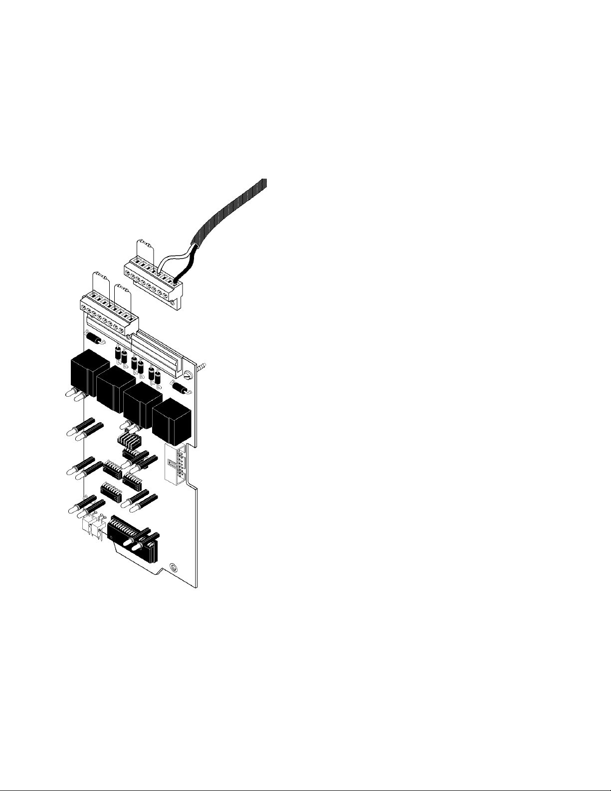
2.1 THE BE-2000 BASIC EQUIPMENT PACKAGE
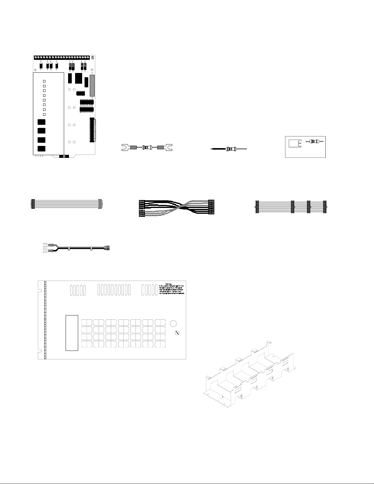
CPU-2000 CENTRAL PROCESSOR MODULE
This module is the heart of the system. It controls and monitors the system modules
and provides a full accounting of system status. In addition, the CPU contains two
notification appliance circuits, a Remote Signaling Municipal Tie Circuit, and FormC alarm and trouble contacts. Field programming of the system is accomplished from
this module via the use of the Programming Key. Slide-in labels for programming,
control, and system operation are provided with the CPU, as well as end-of-line and
dummy load resistors.
Power Ribbon
(71085)
Main Bell Power Harness
(71093)
End-of-Line Resistor
(ELR)
4.7K, 1/2 watt (71252)
Power Harness
(71086)
Dummy Load Resistor
4.7K, 1/2 watt (71245)
First-Row Ribbon Cable
(71087)
VP-1F Vented Dress Panel
Covers the top row of modules in the
cabinet.
KEY #___ PWD#___
Programming
Key (PKB)
CHS-4 Chassis
For the mounting of up to four modules or four AVPS-24F
Audio-Visual Power Supplies. The CHS-4 occupies one
row in the CAB-A3F or CAB-B3F cabinet.
8
S2000 15017 Rev H 10/08/96 P/N 15017:H
Page 9
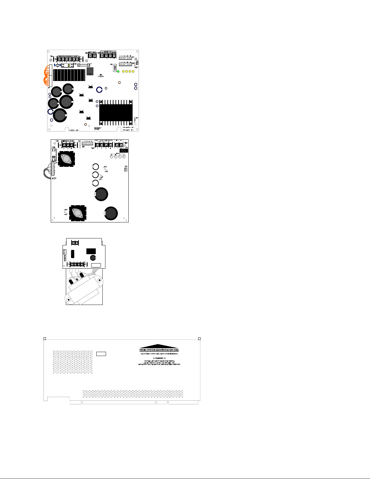
2.2 POWER SUPPLIES
MPS-24AF/MPS-24AFE
The MPS-24AF supplies the regulated power needed to run system modules. It
also supplies up to 3 amps of regulated notification appliance power, permitting
the use of a variety of standard UL-listed 24 VDC Notification Appliances
(refer to the FireLite Device Compatibility Document, Document 15384 for a
complete list of notification appliances). Up to one amp of resettable power is
available for four-wire smoke detectors. The MPS-24AF contains an integral
battery charger for 9.5 to 55 AH batteries.
MPS-24BF/MPS-24BFE
The MPS-24BF supplies the regulated power needed to run the system's modules. It also supplies up to 2.0 amps of RMS-regulated notification appliance
power, permitting the use of a variety of standard UL-listed 24 VDC notification appliances (see Document 15384 for a complete list). Up to 200mA of
resettable power is available for four wire smoke detectors. The MPS-24BF
contains an integral battery charger capable of charging batteries in the 6.5 to
17 AH range. Includes two sets of battery cables, one with 1/4" lug-type connectors for larger batteries and one set with 3/16" lug-type connectors.
AVPS-24F/AVPS-24FE AUDIO VISUAL POWER SUPPLY
Supplies power to notification appliance circuits only. Unfiltered, unregulated, 3.0 amps
maximum. Assumes one position on the CHS-4 Chassis. Provided with a trouble cable
for connection to the main power supply. See Document 15384 for a list of compatible,
UL-listed notification appliances. The AVPS-24F may be installed under any module
except the CPU or modules with expander board installed.
BP-3F BATTERY DRESS PANEL
Covers the main power supply and the batteries in the
cabinet (provides dead-front where required).
S2000 15017 Rev H 10/08/96 P/N 15017:H
9
Page 10
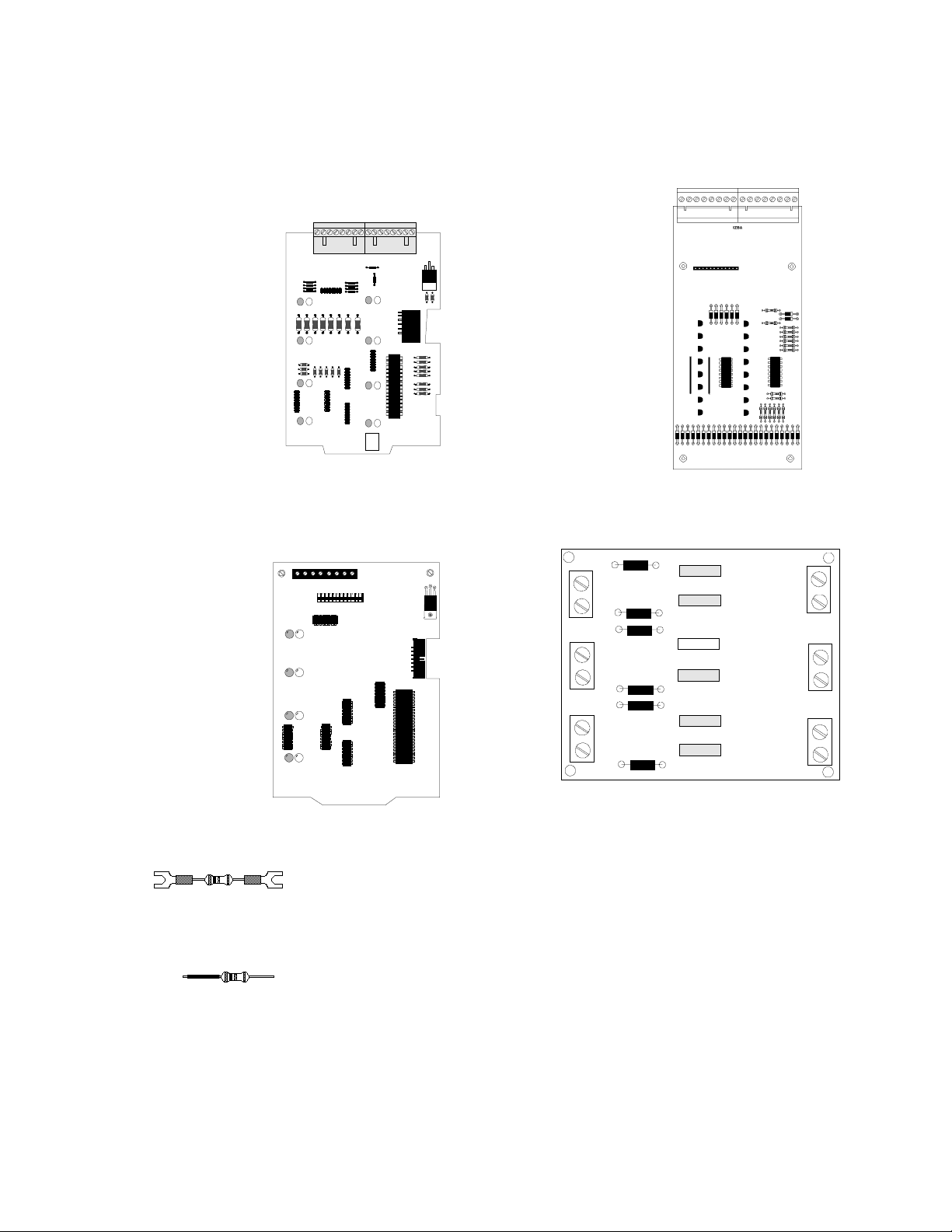
2.3 MODULES
IZ-8F INITIATING
ZONE MODULE
This module provides eight
Style B initiating device circuits. Circuits are power limited and can be programmed for
standard fire, Waterflow Alarm,
Supervisory service, Non
Alarm or Command Inputs.
Also provided are eight end-ofline and eight dummy load resistors.
IZ-4F INITIATING
ZONE MODULE
This module provides four
Style B initiating device circuits. Circuits are power limited and user programmable for
standard fire, Waterflow Alarm
or Supervisory service. Also
provided are four end-of-line
and four dummy load resistors.
IZE-AF INITIATING
ZONE EXPANDER
Converts the eight initiating device circuits on the Initiating
Zone Module (IZ-8F) to Style
D operation. The expander
plugs into the bottom of the IZ8F.
Note: This module will not support an IZE-AF Expander.
End-of-Line Resistor (ELR)
4.7K, 1/2 watt (71252)
Dummy Load Resistor
4.7K, 1/2 watt (71245)
10
RS-1459 MODULE
The RS-1459 module is used in conjunction with
the Remote Station or Municipal Box Output. The
RS-1459 is NOT required for the Municipal Box
Circuit if wiring remains in conduit, wire length is
less than 1000 meters, and wiring does not cross
any power lines. All conditions must be met according to page 23 of this manual (refer to Figure
4-3). For more information on the RS-1459 module, refer to the RS-1459 Product Installation Drawing, Document 50519.
S2000 15017 Rev H 10/08/96 P/N 15017:H
Page 11
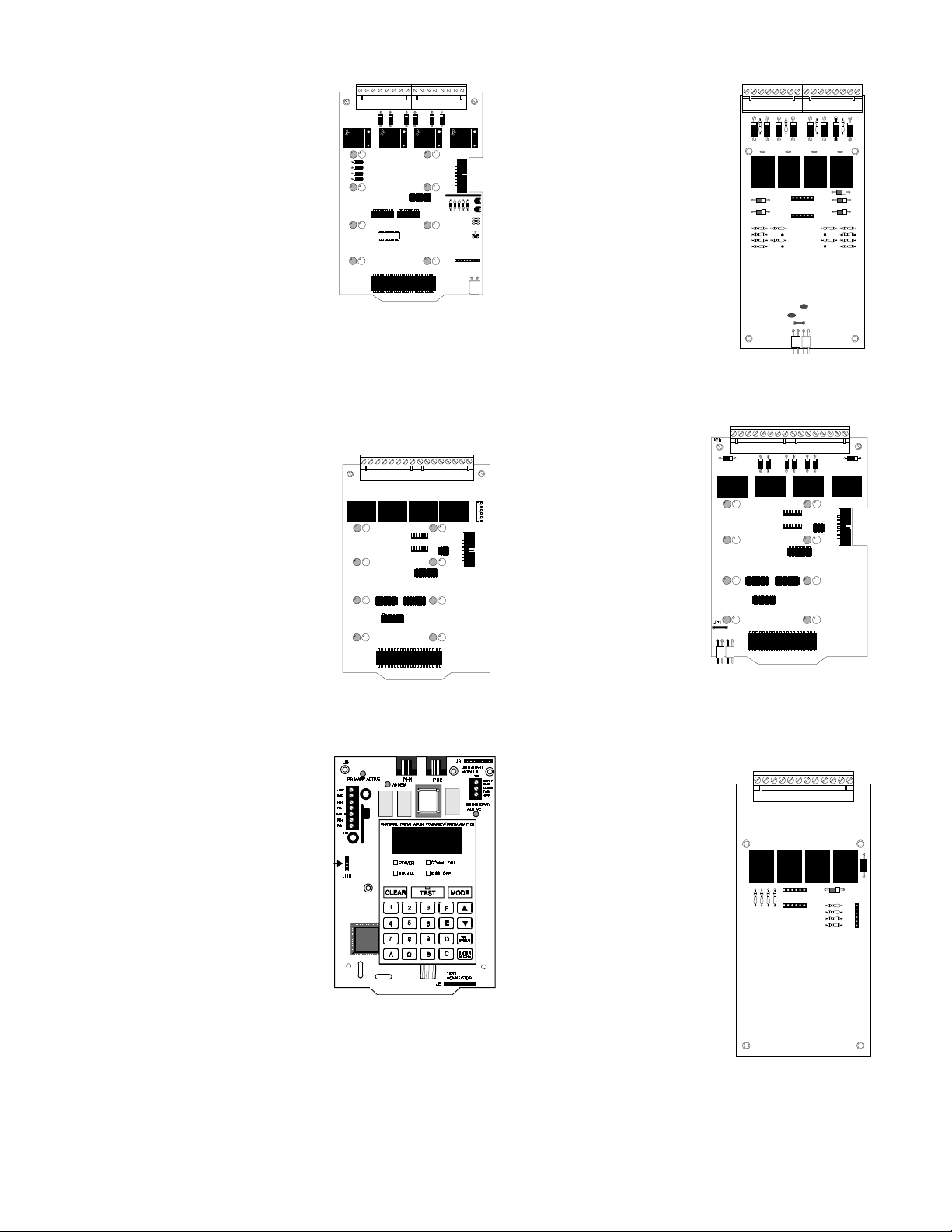
IC-4F INDICATING CIR-
CUIT MODULE
ICE-4F INDICATING CIR-
CUIT EXPANDER
Provides four notification appliance
circuits for Style Y or Style Z operation. Maximum signaling current is
3.0 amps (3 amps max per circuit).
Circuits are field programmable to
respond to a single initiating zone, a
group of zones, or all initiating
zones. End-of-line resistors, dummy
load resistors, and an Auxiliary Bell
Power Harness are provided with
each module. For California Code see Figure 4-7.
CR-4F CONTROL RELAY
MODULE
Provides four standard dry FormC alarm contacts rated for 5 amps
@ 120 VAC or 30 VDC (resistive).
Each relay is field programmable
to respond to a single device circuit, a group of circuits, or all initiating device circuits.
Expands the IC-4F to a total of eight
notification appliance circuits (either
Style Y or Style Z). Circuit ratings
are identical to those of the IC-4F.
An Auxiliary Bell Power Harness is
provided with each expander. The
expander plugs into the back of the
IC-4F.
TC-2F/TC-4F TIME
CONTROL MODULE
The TC-2F module can be
configured for one of five
functions. Pre-signal evacuation or dual code evacuation,
and standard release service,
triple-coded release, or IRI release. For more information,
refer to the TC-2F Manual.
The TC-4F can provide either
four releasing circuits or four
power-limited dual code
evacuation circuits. For more information, refer to the TC4F Manual.
THE UNIVERSAL DIGITAL
ALARM COMMUNICATOR/
TRANSMITTER
The UDACT-F may be used with
the FireLite MS-9200 and
Sensiscan 2000 control panels.
The UDACT-F transmits system
status to UL-Listed Central Station
Receivers via the public switched
telephone network. The UDACTF is compact in size and may be
mounted inside the host control
panel or may mount externally in
a separate enclosure. EIA-485 annunciator communications bus
and 24 volt (nominal) connections are required. The UDACT-F
is capable of reporting 198 points or 56 zones when used with
the MS-9200 and 56 zones when used with the Sensiscan 2000.
S2000 15017 Rev H 10/08/96 P/N 15017:H
CRE-4F CONTROL
RELAY EXPANDER
Expands the capacity of the
Control Relay Module (CR4F) to eight Form-C alarm relays. Relays are identical to
those on the CR-4F. The expander plugs into the back of
the CR-4F or IC-4F.
11
Page 12
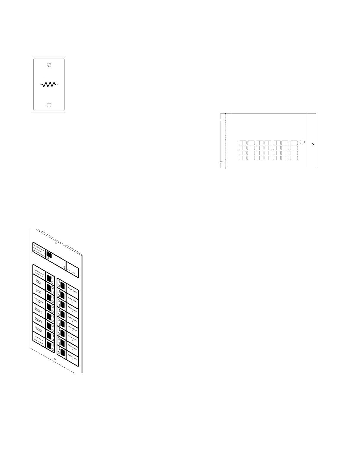
2.4 EQUIPMENT FOR THE SENSISCAN 2000
F-ELR
The F-ELR Resistor Assortment is required for use in Canada. It includes a variety of ELR
values for supervising IZ or IC circuits. The desired resistor mounts to a single ELR plate (illustrated). Included with the F-ELR:
47K, 27K, 10K, 6.8K, 4.7K, 2.2K, 1.8K, 470 and 120 ohm resistors.
CHS-4F
The CHS-4F expansion chassis package is required for all CAB-B3F installations. The CHS-4F includes the CHS-4 Chassis, the MP-1F Module Dress
Panel (illustrated), and an Expander Ribbon Cable.
AFM-16ATX
The AFM-16ATX Annunciator Control Module contains 16 red alarm and 16 yellow trouble LEDs, 16 momentary touchpad switches for controlling each point, a system trouble LED, an ON LINE/POWER LED, and a local piezo sounder with
a silence/acknowledge switch for audible indication of alarm and trouble conditions at each annunciator. The AEM-16ATF
Annunciator Expander Module expands the AFM-16ATX by 16 system points. One to three of these expander modules
can be supported by an AFM-16ATX to a maximum of 64 system points.
MP-1F Module Dress Panel
AFM-32AX
The AFM-32AX Annunciator Control Module contains 32 red alarm LEDs, a System Trouble LED,
an ON LINE/POWER LED, and a local piezo sounder with a silence/acknowledge switch for audible indication of alarm and trouble conditions at each annunciator. The AEM-32ATF Expander
Module expands the AFM-32AX by 32 system points. One expander module can be supported by
an AFM-32AX, providing a maximum of 64 points.
AFM-16ATF
The AFM-16ATF Annunciator Fixed Module contains 16 red alarm and 16 yellow trouble LEDs,
16 momentary touch-pad switches, a system trouble LED, an ON LINE/POWER LED, and a local
piezo sounder with a silence/acknowledge switch for audible indication of alarm and trouble conditions at each annunciator. Only One annunciator may be used in a system.
AFM-32AF
The AFM-32AF Annunciator Fixed Module contains 32 red alarm LEDs, a System Trouble LED,
an ON LINE/POWER LED, and a local piezo sounder with a Local Silence/Acknowledge switch
for audible indication of alarm and trouble conditions. Only one annunciator may be used in a
AFM-16ATX
system.
AFM-16AF
The AFM-16AF Fixed Annunciator module is intended for use in systems that require 16 alarm annunciator points or less.
Only one annunciator may be used in a system.
12
S2000 15017 Rev H 10/08/96 P/N 15017:H
Page 13
2.5 CABINETS
The CAB-A3F and CAB-B3F cabinet assemblies consist of a backbox and a locking door with two keys. The backbox and
door can be ordered separately or as a complete package.
CAB-A3F
CAB-B3F
TR-A3R/TR-B3R TRIM RING
For semi-flush mounting of the cabinet
S2000 15017 Rev H 10/08/96 P/N 15017:H
13
Page 14
SECTION THREE: I NSTALLATION
The control panel's modules communicate with the CPU
through a common ribbon cable connection.
The following procedures, diagrams, and instructions must be followed precisely to avoid damage to the control panel and
its associated equipment. Reliability depends to a great extent upon proper installation and maintenance.
Cabinet - Mount the cabinet and draw all field wiring through the knockouts provided. If the door is left-hanging,
❏❏
❏
❏❏
mount door hardware now, due to the main power supply resting on lower hinge.
NOTE
Do not draw wiring into the bottom nine inches of the cabinet or conflict with the power
supply and batteries may result.
Main Power Supply - Mount the main power supply to the cabinet as illustrated in Figure 3-3. Do not wire anything
❏❏
❏
❏❏
at this time!
Chassis- Mount all chassis. Refer to Figure 3-2 for installation of the CHS-4 chassis.
❏❏
❏
❏❏
Audio Visual Supplies - If any optional audio visual power supplies are to be employed, mount them to the chassis.
❏❏
❏
❏❏
Refer to Figure 3-4 for mounting of the AVPS-24F/AVPS-24FE to the CHS-4.
Audio Visual Cables - Connect the trouble cable(s) and Auxiliary Bell Power Harness to the audio visual power
❏❏
❏
❏❏
supply as illustrated in Figure 5-4.
❏❏
❏
❏❏
Preliminary System Wiring- The main power supply and any audio visual power supplies should be wired at this
time while the terminals are readily accessible. Refer to Section Five to wire the main power supply, audio visual
power supplies or the R45-24.
14
S2000 15017 Rev H 10/08/96 P/N 15017:H
Page 15

Module Ribbon Cables - Connect the 1st Row Ribbon Cable to the CPU as illustrated in Figure 3-8. For each
❏❏
❏
❏❏
additional row of modules installed in the cabinet, connect an Expander Row Ribbon Cable to the CPU.
CPU - Install the CPU module in the top left cabinet position as illustrated in Figure 3-7. Connect the Power Ribbon
❏❏
❏
❏❏
and Power Harness between the CPU and the main power supply as illustrated in the respective figure in Section Four.
Module Expander Boards - If expander boards are to be used with a module, install as illustrated in Figure 3-5.
❏❏
❏
❏❏
Modules - Mount each module in its respective chassis position as illustrated in Figure 3-6. Connect the CPU Row
❏❏
❏
❏❏
Ribbon Cable and the Expander Row Ribbon (in CAB-B3F installations) to the modules. Field-wire each module,
using the following figures for reference:
CPU-2000 Figure 4-3, 4-4
IZ-8F or IZ-4F (Style B) Figure 4-5
IZ-8F requires IZE-AF (for Style D) Figure 4-6
IC-4F/ICE-4F Figure 4-7 (ICE-4F Optional)
CR-4F/CRE-4F Figure 4-8 (CRE-4F optional)
TC-2F (Refer to the TC-2F Manual)
TC-4F (Refer to the TC-4F Manual)
AFM-16ATF, AFM-32AF,AFM-16AF,
AFM-16ATX,AFM-32AX (Refer to respective manual.)
UDACT-F Figure 6-1
Power-on-check - Apply AC power to the control panel. Do not connect the batteries at this time! To silence the
❏❏
❏
❏❏
audible trouble sounder, push the ACKNOWLEDGE switch on the CPU. The system should reflect the following
status.
On the CPU
Green AC POWER indicator should be on.
The BATTERY FAIL indicator will be on due to the absence of batteries.
SYSTEM TROUBLE and POWER FAILURE indicators should be on due to the absence of batteries.
MODULE FAILURE indicator may light shortly after AC power is applied (applies only to a system that has
not been previously configured).
On each module
The yellow trouble indicators may come on approximately ten seconds after AC power is applied (applies
only to a system that has not previously been configured).
On each AVPS
The yellow trouble indicators will light due to the absence of batteries.
On the main power supply
Failure of the AC POWER indicator, or the presence of indications not mentioned above may suggest an installation
problem. Carefully review the installation instructions to isolate the source.
Programming - To configure and program the system, refer to field programming in Section Seven.
❏❏
❏
❏❏
Batteries - Once the system has been programmed and is functional, connect the batteries. Ensure that all indicators
❏❏
❏
❏❏
except AC POWER are extinguished.
Testing - Fully field test the system by conducting the test procedure in Section Nine.
❏❏
❏
❏❏
Dress Panels - Complete installation of the system by installing the cabinet door first, followed by the dress panels
❏❏
❏
❏❏
(VP-1F and MP-1F).
S2000 15017 Rev H 10/08/96 P/N 15017:H
15
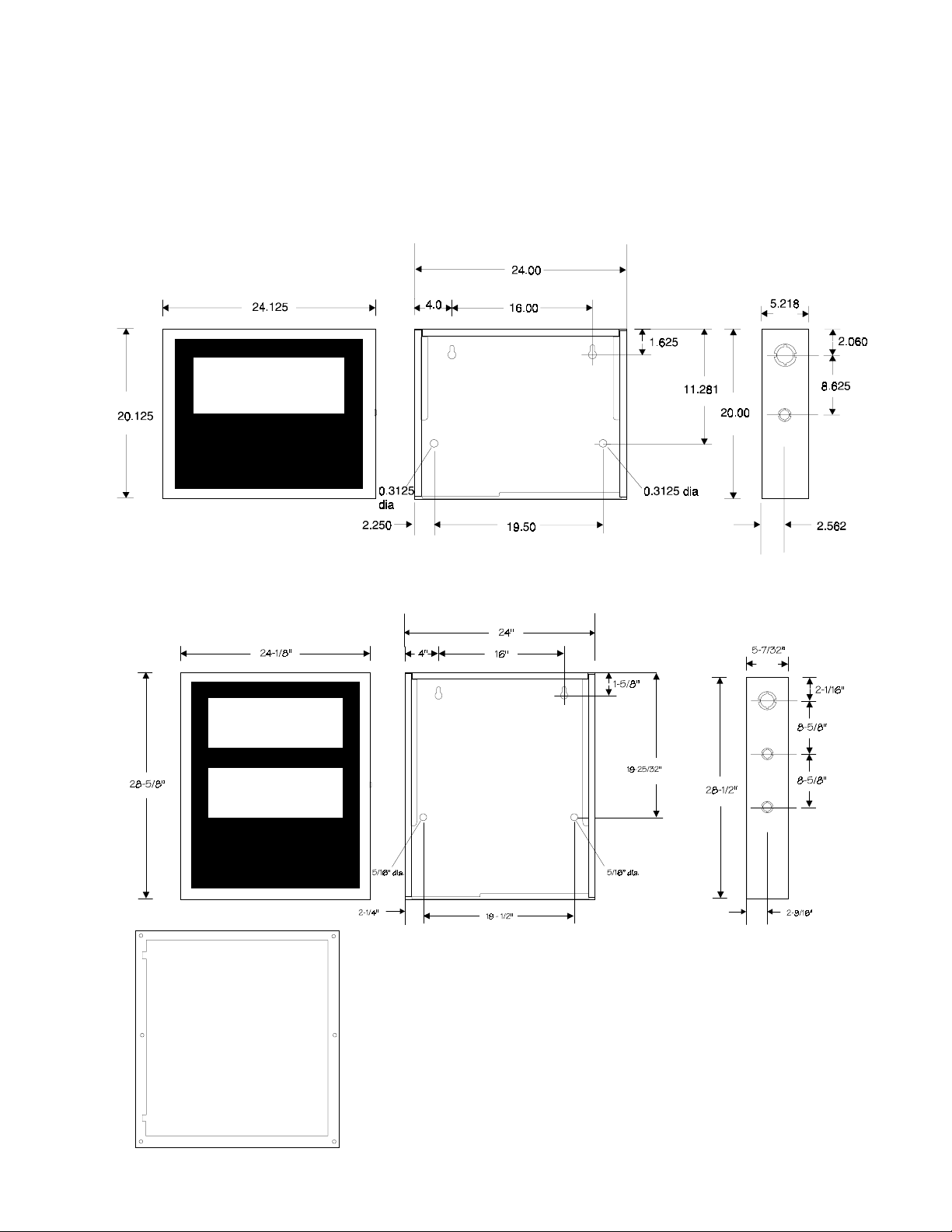
Page 16
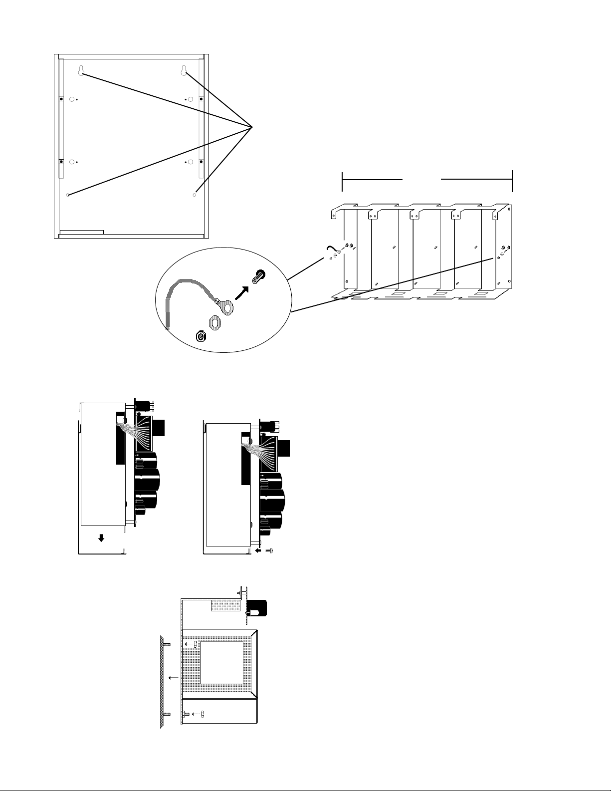
FIGURE 3-1 : MOUNT THE CABINET BACKBOX
Mount the backbox in a clean, dry, vibration free area, using the four
holes provided in the back surface of the cabinet.
Grounding Cable
17-15/16
FIGURE 3-2: INSTALL A CHS-4
Install a CHS-4 in each row of the cabinet that will employ Sensiscan 2000 modules. For proper grounding of
the modules to the cabinet, connect a grounding cable to
one of the chassis mounting screws as illustrated.
FIGURE 3-3: INSTALL THE MAIN POWER
SUPPLY
Place the MPS-24AF/MPS-24AFE (shown) or MPS-24BF/
MPS-24BFE into the bottom of the cabinet, ensuring that
the upper bracket engages the support bracket on the cabinet. Secure the bottom of the power supply to the bottom
cabinet support with the provided screws.
FIGURE 3-4: INSTALL THE AVPS
16
CHS-4
Install any optional AVPS-24F/AVPS-24FE over the screw
AVPS
S2000 15017 Rev H 10/08/96 P/N 15017:H
mounts on the CHS-4 and secure with the two provided nuts.
Page 17
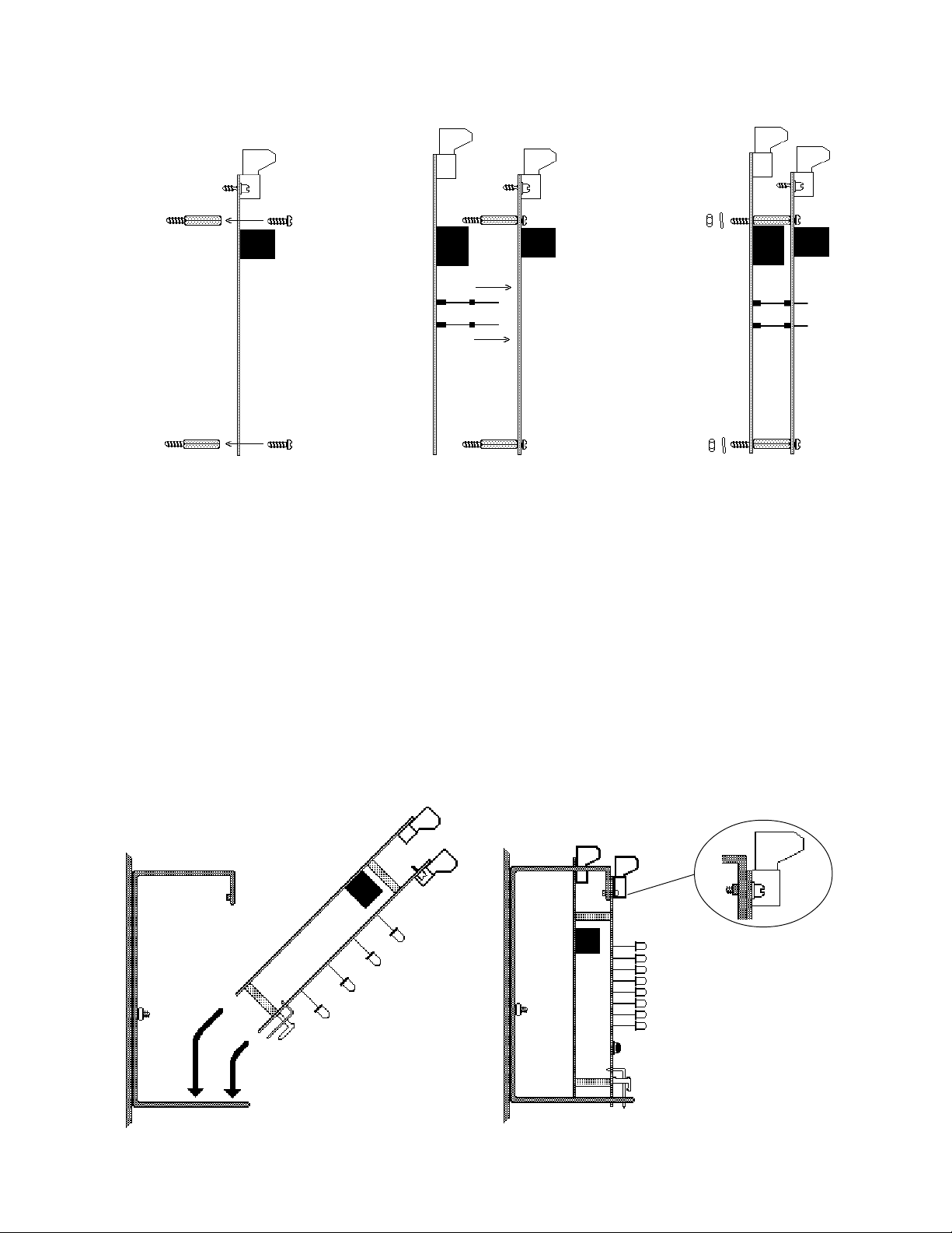
FIGURE 3-5: MOUNTING MODULE EXPANDERS
Module
Step 1:
Attach four standoffs to the
module using the four screws
provided.
Expander Module
Step 2:
Insert the pins on the expander board into
the connector on the module and press the
two boards together, ensuring that the pins
are properly aligned.
FIGURE 3-6: MOUNTING MODULES IN THE CHASSIS
Step 1:
Angle the module into the cabinet so that the upper
board edge slips into the cabinet slot as shown.
Step 2:
Push the upper end of the module into the cabinet and secure
with two module screws. Straighten LEDs so that they extend
from the board at a 90 degree angle.
Expander/Module
Step 3:
Secure the module/expander assembly with the four nuts and lock
washers provided.
Cabinet
Cabinet
S2000 15017 Rev H 10/08/96 P/N 15017:H
17
Page 18
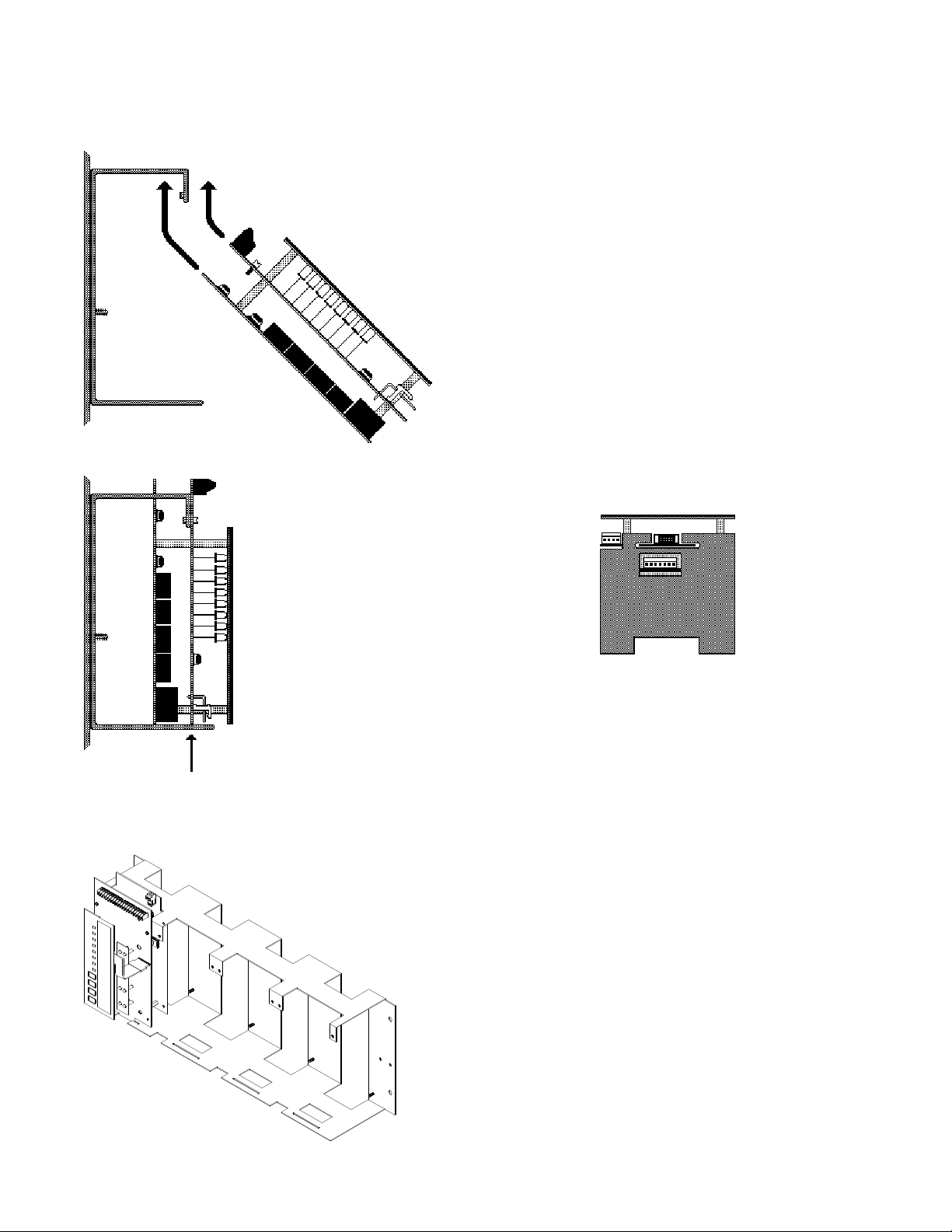
FIGURE 3-7: MOUNTING THE CPU-2000
Step 1:
Insert the CPU Module into the left-most
cabinet slot, angling the front end of the
module into position as shown.
Step 2:
Push the back end of the module down into the
cabinet and pull down until the upper board
engages the slot on the chassis as shown.
Bottom View
18
Step 3:
Align the module screws with the
thread-holes on the chassis and secure
in place.
S2000 15017 Rev H 10/08/96 P/N 15017:H
Page 19
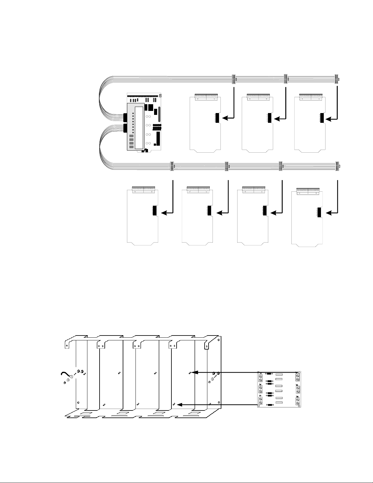
FIGURE 3-8: CONNECTING ROW RIBBON CABLES TO MODULES
The ribbon cable is notched at the module ends.
First Row
Ribbon
(71087)
Connect to upper-
most connector on
CPU.
Expander
Ribbon
(71088)
FIGURE 3-9: MOUNTING THE RS-1459 IN THE CHS-4
Mount the RS-1459 to two studs in any position on the back of the CHS-4. Use the provided standoffs and screws to mount
the module. Refer to Figure 4-3 for information on wiring the module.
RS-1459
CHS-4
S2000 15017 Rev H 10/08/96 P/N 15017:H
19
Page 20
SECTION FOUR: FIELD WIRING THE MODULES
The IC-4F Notification Circuit Module, as well
as the IZ, CR and TC modules feature removable
terminal blocks that ease installation and servicing of the control panel.
20
S2000 15017 Rev H 10/08/96 P/N 15017:H
Page 21
4.1 UL POWER-LIMITED WIRING REQUIREMENTS
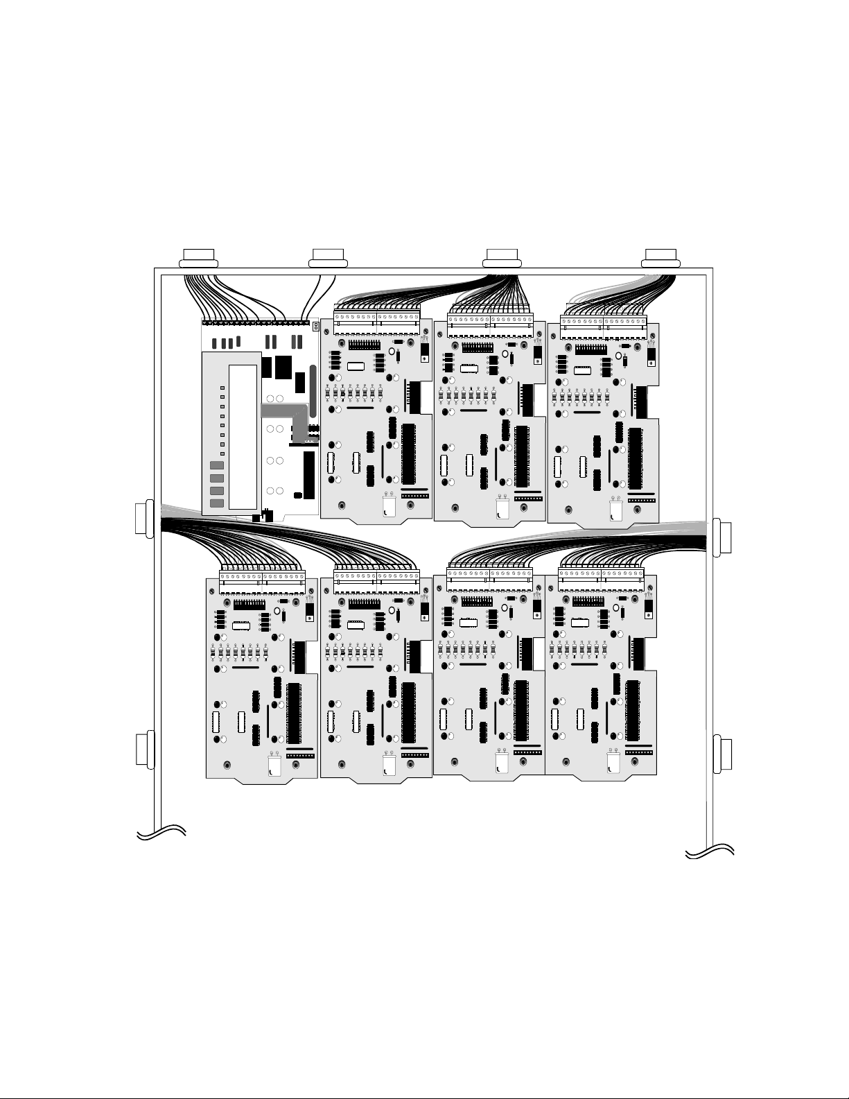
Power-limited and nonpower-limited circuit wiring must remain separated in the cabinet. All power-limited circuit wiring
must remain at least 0.25" away from any nonpower-limited circuit wiring. Furthermore, all power-limited and nonpowerlimited circuit wiring must enter and exit the cabinet through different knockouts and/or conduits. A typical wiring diagram
for the Sensiscan 2000 is shown below.
Nonpowerlimited
circuits
Power-limited
circuits
Nonpower-limited
circuits
Power-limited
circuits
Power-limited
circuits
Po werlimited
circuits
Power supplies in bottom of cabinet - see Figure 4-2
Figure 4-1: Typical Wiring Diagram for UL Power-limited Wiring Requirements
S2000 15017 Rev H 10/08/96 P/N 15017:H
21
Page 22
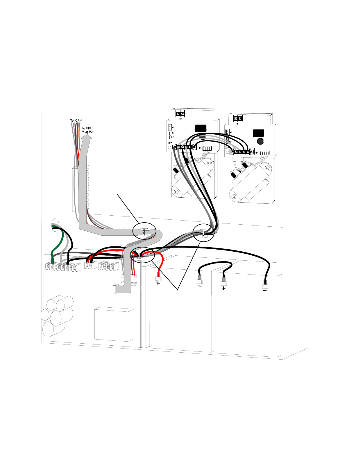
4.2 UL POWER-LIMITED WIRING REQUIREMENTS - POWER SUPPLIES
The diagram below shows a typical Sensiscan 2000 installation and is provided as a guide for proper wiring placement. The
AC and battery wiring are not power-limited. A separation of at least 0.25" must be maintained between power-limited and
nonpower-limited wiring. Install the tie wraps and adhesive squares as indicated below.
Adhesive square and tiewrap on back of cabinet
affixing power-limited
wiring.
22
Adhesive square and
tie-wrap on back of
cabinet and on top of
power supply chassis
affixing nonpowerlimited wiring.
Figure 4-2: Power-limited and Nonpower-limited Wiring for Power Supplies
S2000 15017 Rev H 10/08/96 P/N 15017:H
Page 23
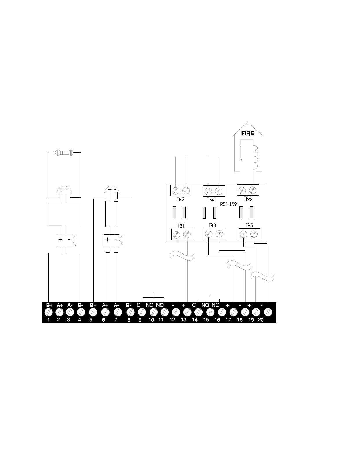
Typical Supervised Power-limited
Notification Appliance Circuits
Use only compatible, UL-listed notification appliances (see the Device Compatibility Document, 15378). Max current per circuit is 3.0
amps, subject to the limitations of the power
supply.
Style Y
4.7K, 1/2 watt ELR,
Part # 71252.
Non-Supervised
Remote Station Outputs
Non-Supervised, Power-limited
(Standby polarity shown)
24 VDC (nominal). 10 mA max rated
current. Internal resistance = 1360 ohms
(nominal).
Intended for connection to the polarity
reversal circuit of a remote station receiving unit (Fire-Lite Model RS-82) having
compatible ratings.
Remote Station
Trouble Output
Remote Station
Alarm Output
Municipal Box Output
Nonpower-limited, supervised for
open circuits. Max. Current (short
circuit) = 0.6 amps. Max. Voltage
(open circuit) = 27.6 VDC. Max.
Wire Resistance = 5 ohms.
Municipal Box Ratings
Trip current = 0.25 Amps (min)
Coil voltage = 3.65 VDC (min)
Coil resistance = 14.6 ohms (max)
UL-listed
24 VDC
Polarized Bell
UL-listed
24 VDC
Polarized Horn
Style Z
System
Trouble
Contacts
(power-limited
source only)
2A @ 30VDC
1A @ 120VAC
(resistive)
Programmable
Alarm
Contacts
(power-limited
source only)
5A @ 30VDC
5A @ 120VAC
(resistive)
Figure 4-3: Field Wiring the CPU
Municipal box wiring
must be run in conduit.
Municipal Box Output
Nonpower-limited and supervised (for open circuits). Wiring can leave the building.
1) The Remote Station Alarm Output and the Municipal Box Output must not be used simultaneously.
2) Notification appliance circuits, Remote Station Trouble output, and the Remote Station Alarm output are power-
limited and may be connected to limited-energy cable.
3) Wire notification appliances according to the manufacturer's instructions packaged with each device.
4) Terminal blocks will accept #12 to #22 AWG wire.
5) Size notification circuit wire for a maximum drop of 2 volts DC at the last device on the circuit.
6) The RS-1459 module is required when the Remote Station or Municipal Box Output is connected to a circuit that
exits the protected premises. Exception - The RS-1459 module is not required for the Municipal Box Circuit if
ALL of the following conditions exist: (1) wiring is in conduit, (2) wire length is less than 1000 meters, and (3)
wiring does not cross any power lines.
S2000 15017 Rev H 10/08/96 P/N 15017:H
23
Page 24

DUMMY-LOADING UNUSED CIRCUITS ON THE CPU
An unused notification circuit must be terminated with
one dummy load resistor.
If the Municipal Box Output is not to be used,
it must be terminated with a dummy load resistor.
4.7K, 1/2-watt Resistor
Part # 71245
4.7K, 1/2-watt Resistor
Part # 71245
THE EIA-485 INTERFACE
The Sensiscan 2000 communicates with the AFM serial annunciators through the EIA-485 interface on the CPU. Maximum
distance is 6000 feet and maximum resistance is 100 ohms.
EIA-485 Interface
Supervised and Power-limited
EIA-485 (+)
EIA-485 (-)
24
TB2
Figure 4-4: Connecting the EIA-485 Interface
S2000 15017 Rev H 10/08/96 P/N 15017:H
Page 25

FIGURE 4-5 NFPA STYLE B FIELD WIRING OF INITIATING ZONE MODULES
ABCD E*F*G*H*
b+ b- b+ b- b+ b- b+ b- b+ b- b+ b- b+ b- b+ b-
AE
BF
C G
4.7K, 1/2 watt ELR, Part # 71252.
Manual Pull Station
UL-listed two-wire
Photo smoke detector
2
5
DH
*NOTE: IZ-4F contains only circuits A, B, C and D.
1) Initiating device circuits are supervised, power limited and may be connected to limited-energy cable, except for initiating devices that require
24 VDC power.
2) Use only the compatible, UL-listed two-wire smoke detectors that are
listed in FireLite Document 15384.
3) For connection of four-wire smoke detectors, refer to Section Six.
4) Wire initiating devices according to the manufacturer's instructions pack-
aged with each device.
5) For Canada, model F-ELR End-of-Line Resistor Assembly required.
6) Maximum line resistance is 100 ohms.
UL-listed two-wire
Ion smoke detector
2
Typical NFPA Style B
Initiating Device Circuit
Supervised and Power-limited
Dummy load all unused circuits
with 4.7K ELR (71245).
S2000 15017 Rev H 10/08/96 P/N 15017:H
25
Page 26
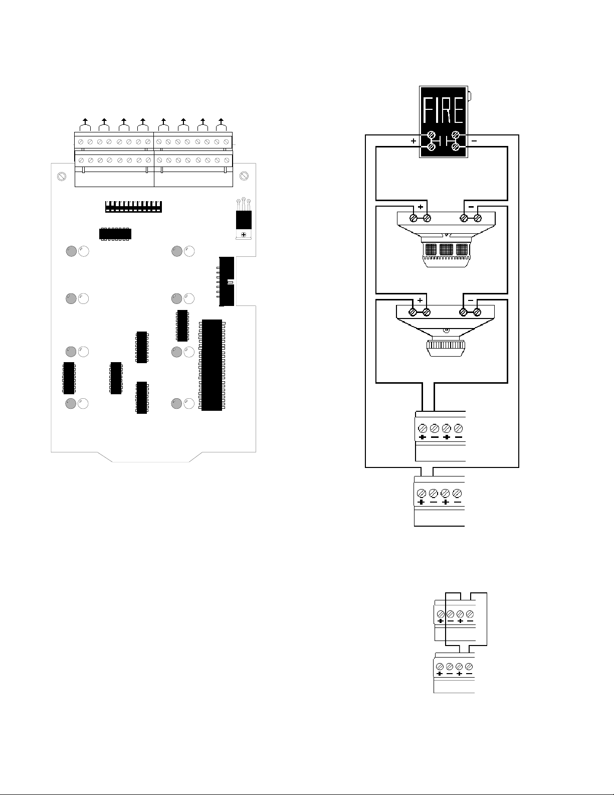
FIGURE 4-6: STYLE D FIELD WIRING OF IZ-8F INITIATING ZONE MODULE WITH IZE-AF
EXPANDER
ABCD E FGH
a+ a- a+ a- a+ a- a+ a- a+ a- a+ a- a+ a- a+ a-
b+ b- b+ b- b+ b- b+ b- b+ b- b+ b- b+ b- b+ b-
Manual Pull Station
AE
Two-wire Photo smoke detector
BF
C G
DH
IZ-8F/IZE-AF
1) Initiating device circuits are supervised, power limited and may be
connected to limited-energy cable, except for initiating devices that
require 24 VDC power.
2) Use only the compatible, UL-listed two-wire smoke detectors that
are listed in FireLite Document 15384.
3) For connection of four-wire smoke detectors, refer to Section Six.
4) Wire initiating devices according to the manufacturer's instructions
packaged with each device.
5) The IZ-4F does not support the IZE-AF expander module and therefore cannot be wired for Style D circuits.
6) Maximum line resistance is 100 ohms.
two-wire Ion smoke detector
2
Typical NFPA Style D
Initiating Device Circuit
Supervised and Power-limited
26
Dummy load all unused circuits
with a 4.7 ELR (71245).
S2000 15017 Rev H 10/08/96 P/N 15017:H
Page 27

FIGURE 4-7: NFPA STYLE Y/Z FIELD WIRING OF THE IC-4F INDICATING CIRCUIT MOD-
ULE AND ICE-4F EXPANDER
E F G H
b+ a+ a- b- b+ a+ a- b- b+ a+ a- b- b+ a+ a- b-
A B C D
b+ a+ a- b- b+ a+ a- b- b+ a+ a- b- b+ a+ a- b-
A E
Optional ICE-4F Indicating Circuit Expander. Positions E, F, G, and H
are active only with this board installed.
Typical
NFP A Style Y
Notification Appliance
Circuit
4.7K, 1/2 watt ELR,
Part # 71252.
5
Typical
NFPA Style Z
Notification Appliance
Circuit
UL-listed
24 VDC
Polarized Bells
UL-listed
24 VDC
Polarized Horns
Jumper
unused
circuits
B F
Jumper
unused
circuits
CG
D35
DH
JP2
J5 J6
Cut this diode for California Code
IC-4F/ICE-4F
1) Notification appliance circuits are supervised, power limited and may be connected to limited-energy cable.
2) Use only compatible, UL-listed notification appliances that are listed in Document 15384.
3) Wire notification appliances according to the manufacturer's instructions packaged with each device.
4) Max current per circuit is 3.0 amps, subject to the limitations of the source of power (MPS-24AF/MPS-24AFE, MPS24BF/
MPS-24BFE, or AVPS-24F/AVPS-24FE).
5) For Canada, model F-ELR End-of-Line Resistor Assembly is required.
6) Size wiring for a maximum voltage drop of two volts at the last device on the circuit.
7) The IC-4F is California Code programmable (microprocessor Rev. B or higher of IC-4F). To program for California Code, cut
diode D35.
8) Cut jumper JP1 and JP2 to separately power notification appliance circuits 1 & 2 or 3 & 4. Separate 3 amps max. power
supplies must be tied to J5 & J6.
S2000 15017 Rev H 10/08/96 P/N 15017:H
27
Page 28
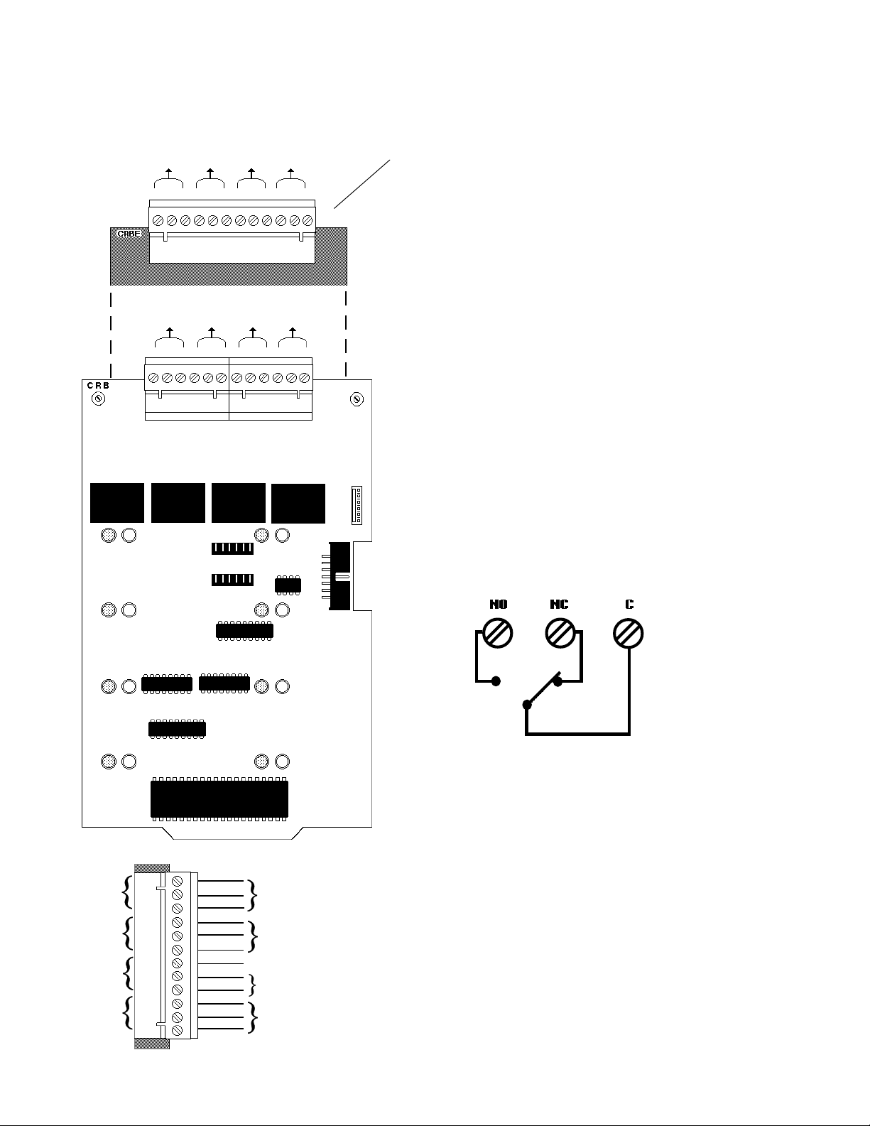
FIGURE 4-8: FIELD WIRING OF THE CR-4F CONTROL RELAY MODULE AND THE CRE-4F
CONTROL RELAY EXPANDER
EFGH
no nc c no nc c no nc c no nc c
* Optional CRE-4F Control Relay Expander. Positions E, F, G and H
are active only with this board installed.
ABCD
no nc c no nc c no nc c no nc c
AE
★
These Form-C gold-plated, silver alloy relay contacts are for
medium duty switching and are not intended for Motor Control or Pilot Duty.
UL contact ratings are 5 amps @ 125 volts AC (resistive) or
30 volts DC (resistive) and 2 amps @ 125 volts AC (inductive).
Activation of a CR-4F or CRE-4F relay occurs automatically when an alarm is detected on a selected (programmed)
Initiating Device Circuit.
Note: Refer to the power-limited label located on the FACP door.
Make a notation on the label for each circuit being employed as
a nonpower-limited circuit. (Refer to the example on the label).
★
★
★
Nonpower-limited and power-limited wiring must have a minimum
BF
CG
D H
distance of 0.25" wire to wire and must enter and exit from different
knockouts. If this module is used to drive nonpower-limited and
power-limited circuits, please follow the instructions below.
1) Skip a set of dry contacts to maintain the 0.25" required space
Relay 1
Relay 2
Relay 3
Relay 4
NO
NC
NO
NC
NO
NC
NO
NC
Power-limited
C
C
C
C
Circuit
Power-limited
Circuit
no connection
Nonpower-limited
Circuit
Nonpower-limited
Circuit
between power-limited and nonpower-limited circuits. The wiring
of this module must follow UL Power-limited Wiring Requirements.
2) If this module is needed to drive power-limited and nonpowerlimited relays that are next to each other, refer to the figure to the left
showing a typical connection.
Typical Form-C Contr ol Rela y in Standb y P osition
OR
28
S2000 15017 Rev H 10/08/96 P/N 15017:H
Page 29

SECTION FIVE: THE POWER SUPPLIES
Main Power Suppl y Bell
Power Harness
(71093)
Blue to Bell Pow er (+)
Black to Bell P o w er (-)
Three cables complete the electrical connection between the CPU and the main power supply.
CPU
(Bottom
View)
Power Ribbon
(71085)
Connects to P3
on the main
power supply
Main Power Harness
(71086)
to P2 on the main power
supply
S2000 15017 Rev H 10/08/96 P/N 15017:H
29
Page 30

5.1 THE MPS-24AF/MPS-24AFE MAIN POWER SUPPLY
The MPS-24AF/MPS-24AFE Main Power Supply is capable of powering the control panel continuously during standby and
alarm conditions. A total of 3.0 amps (internal0 @ 24 VDC regulated is available from the main power supply for operating
the system during Standby conditions. No more than 6 amps @ 24 VDC can be drawn from the MPS-24AF.
Figures 5-1 and 5-2 illustrate connections for primary and secondary power to the MPS-24AF Main Power Supply, as well
as terminal and harness connections for the control panel.
CONNECTING THE PRIMARY POWER SOURCE
Primary power required for the MPS-24AF is 120 VAC, 50/60 Hz, 1.8 amps and primary power for the MPS-24AFE is 220/
240 VAC, 50/60 Hz, 0.9 amps. With the breaker at the main power distribution panel turned off, remove the plastic insulating cover from Terminal Block TB1 on the main power supply and connect the system primary power source. Connect the
service ground to TB1 Terminal 2 and ground the power supply assembly to the cabinet with a Chassis Ground cable (71073)
to TB1 Terminal 1. Connect the primary Neutral line to TB1 Terminal 4 and the primary Hot line to TB1 Terminal 6. After
completion of these connections reinstall the plastic insulating cover over the terminal strip. Leave the main power breaker
off until installation of the entire system is complete.
CONNECTING THE SECONDARY POWER SOURCE (24 VDC)
Secondary power (batteries) is required to support the system during loss of primary power. These batteries reside in the
control panel cabinet, or in a separate R45-24 Remote Battery Charger cabinet which can be mounted up to 20 feet away
from the control panel (for connection of an R45-24, refer to Figure 5-6).
Connect the Battery Positive Cable (71071) to TB2 Terminal 1 (+) and the Battery Negative Cable (71072) to TB2 Terminal
2 (-). Do not connect the Battery Interconnect Cable (Part Number 71070) at this time. This connection will be made just
after initial primary system power-up.
FOUR-WIRE SMOKE DETECTOR POWER (24 VDC)
Up to one amp of current for four-wire smoke detectors can be drawn from TB3 Terminals 1 (+) and 2 (-). Power is removed
from these terminals during system reset. This 24 VDC regulated four-wire smoke detector power is power limited but must
be supervised via an UL-listed end-of-line power supervision relay. The power supervision relay is energized by the fourwire power circuit and its contact must be connected in series with an initiating device circuit.
NOTIFICATION APPLIANCE POWER (24 VDC)
Up to 3 amps of regulated power-limited current for powering notification appliances can be drawn from TB3 Terminals
3(+) and 4(). Power is not removed from these terminals during system reset. If a resettable power circuit is desired, cut
JP5 on the MPS-24AF (Note that a maximum of 2 amps is available with JP5 cut.) Note: On the Main Power Supply Bell
Power Harness, the fork lugs must be cut off and wires stripped for connection to the MPS-24AF.
ANNUNCIATOR POWER (24 VDC)
AFM Annunciators can be powered either from the four-wire smoke detector output or the notification appliance power
output. Both outputs provide filtered, regulated, power-limited source required by the annunciators. The power run to the
annunciators is supervised by the annunciator (Loss of Communications error).
SYSTEM HARNESS CONNECTIONS
Internal power for the system is provided via the power harness. Connect this harness from P2 on the main power supply to
the CPU. This same power can be fed to other boards or modules requiring internal power. Signaling between the CPU and
the main power supply is accomplished through connection of the Power Ribbon (71085) to P3 on the MPS-24AF.
30
S2000 15017 Rev H 10/08/96 P/N 15017:H
Page 31

FIGURE 5-1: FIELD WIRING THE MPS-24AF/MPS-24AFE POWER SUPPLY
Four-Wire Smoke Detector/Annunciator Power
24 VDC (20.4-26.4, 200 mV ripple), 1 amp max. Filtered, regulated and resettable.
Power-limited but must be supervised via a UL approved Power Supervision Relay.
+ -
Secondary Power
27.6 VDC, supervised and power-limited.
Fast charge = 2 amps, trickle charge = 20 mA.
Battery Battery +
Notification Appliance/Annunciator Power
+
Power-limited, filtered, regulated,
-
non-resettable , 3 amps (in alarm)
max. P ow er is supervised by output
module (such as an ICM-4F) in the
Sensiscan 2000.
120 VAC, 50/60 Hz, 1.8 amps for MPS-24AF
Primary Power
220/240 VAC, 50/60 Hz, 1.8 amps for MPS-24AFE
Neutral Out Hot In
Earth
Ground
Connect to
chassis via a
Grounding Cable
Assembly.
Neutral In Hot Out
Ground
Battery Fuse
Power Ribbon Connector
Power Harnesses (P2, P4)
Cut R27 to disable
Earth Fault
Detection.
AVPS-24F
Supervisory Cable
Connector
LED Indicators
Ground Fault
Battery Fail
AC Power Fail
(not used)
When employing an
R45-24/R45-24E
Remote Battery
Charger, remove
Jumper JP-1.
S2000 15017 Rev H 10/08/96 P/N 15017:H
* Cut JP5 to convert
Notification Appliance
power
(TB3 Terminals 3-4)
to a resettable,
2-amp maximum
circuit.
DO NOT CUT JP2.
31
Page 32

FIGURE 5-2 HARNESS CONNECTIONS FOR THE MPS-24A
If powering a notification circuit module from the
main power supply, connect the Auxiliary Bell Power
Harness (71091) from J6 on the CPU to J5 on the ICM4F or ICE-4F. See Section 6.9 for more information.
Bottom
view
of ICM-4F
or ICE-4F
(ICM-4F)
(ICE-4F)
Connector orientation
CPU
(bottom view)
7-position end
Main Pwer
Supply Bell
Power
Harness (71093)
Blue wire
+ -
Power Ribbon
(71085)
Wire at 8-position end
Power Harness
(71086)
Connect to P2 or P4.
MPS-24AF/
MPS-24AFE
Note position of Red
32
S2000 15017 Rev H 10/08/96 P/N 15017:H
Page 33

5.2 THE MPS-24BF/MPS-24BFE MAIN POWER SUPPLY
Note: The MPS-24BF has been designed to support single-cabinet row systems only.
This amounts to enough power for the CPU and up to three other modules as a maximum.
The MPS-24BF Main Power Supply is a supply capable of powering the system continuously during standby and alarm
conditions. A total of 750 mA @ 24 VDC regulated is available for operating the system during Standby conditions.
Figures 5-3 and 5-4 illustrate connections for primary and secondary power to the MPS-24BF Main Power Supply, as well
as terminal and harness connections.
CONNECTING THE PRIMARY POWER SOURCE
The MPS-24BF requires 120 VAC, 50/60 Hz, 1.8 amps primary power and the MPS-24BFE requires 220/240 VAC, 50/60
Hz, 0.9 amps. With the breaker at the main power distribution panel turned off, remove the plastic insulating cover from
Terminal Block TB1 and connect the system primary power source. Ground Cable per NEC requirements. Ground the
power supply assembly to the cabinet with a Chassis Ground cable (71073) to TB1 Terminal 2. Connect the primary Neutral
line to TB1 Terminal 3 and the primary Hot line to TB1 Terminal 4. Do not route 120 VAC wiring in the same conduit as
other control panel circuits. After completion of these connections reinstall the plastic insulating cover over the terminal
strip. Leave the main power breaker off until installation of the entire control panel is complete.
CONNECTING THE SECONDARY POWER SOURCE (24VDC)
Secondary power (batteries) is required to support the system during loss of primary power. These batteries reside in the
control panel cabinet. Connect the Battery Positive Cable to TB3 Terminal 1 (+) and the Battery Negative Cable to TB3
Terminal 2 (-). Do not connect the Battery Interconnect Cable at this time. This connection will be made just after initial
primary system power-up.
EARTH FAULT DETECTION
The MPS-24BF automatically employs detection of earth faults in the system (unless Resistor R55 is removed).
FOUR-WIRE SMOKE DETECTOR POWER (24VDC)
Up to 200mA of current for 24 VDC four-wire smoke detectors can be drawn from TB2 Terminals 1 (+) and 2 (-). Power is
removed from these terminals during system reset (unless Jumper JP1 is removed). This regulated four-wire smoke detector
power is power-limited but must be supervised via a UL-listed Power Supervision Relay. The power supervision relay is
energized by the four-wire power circuit and its contact must be connected in series with an initiating device circuit.
ANNUNCIATOR POWER (24VDC)
Up to 200mA of current suitable for powering an AFM-16ATF or AFM-32AF Annunciator can be drawn from TB2 Terminals 1 (+) and 2(-). The power is regulated, power-limited and is supervised by the annunciator.
NOTIFICATION APPLIANCE POWER (24 VDC)
Up to 2.0 amps of regulated power-limited current for powering Notification appliances can be drawn from TB2 Terminals
3 (+) and 4 (-). Power is not removed from these terminals during system reset. Do not connect any type of serial
annunciator (such as an AFM) or any device requiring filtered 24 VDC power to this circuit or damage may result!
SYSTEM HARNESS CONNECTIONS
Internal power for the system is provided via the Power Harness (71086). Connect this harness from P2 on the MPS-24BF
to the CPU. Signaling between the CPU and the main power supply is accomplished through connection of the Power
Ribbon (71085) to P3 on the MPS-24BF.
S2000 15017 Rev H 10/08/96 P/N 15017:H
33
Page 34

FIGURE 5-3 THE MPS-24BF MAIN POWER SUPPLY
Four-Wire Smoke Detector/Annunciator Power
+
+ 24 VDC (20.4-26.4, 200 mV ripple), 200 mA max.
Filtered, regulated and resettable*. Power-limited b ut
-
when used for four-wire detectors, must be supervised by a UL-listed Power Supervision Relay.
+
Primary Power
120 VAC, 1.8 amps max for MPS-24BF
220/240 VAC, 0.9 amps max for MPS-24BFE
Neutral Hot
Earth Ground
Chassis Ground
Connect to chassis with
a Grounding Cable Assembly (Cable # 71073).
Cut R55 to disable
Earth Fault Detection
-
Notification Appliance power (see Caution below)
+ 24 VDC power-limited, RMS-regulated, non-resettab le,
2.0 amps (in alarm) max. Power is super vised by output
module such as an IC-4.
powering annunciators.
CAUTION: The +24 VDC provided on TB2 Terminal 3 is
power-limited only when used with the minus return on
TB2 T erminal 4.
minal 2 with the +24 VDC power on TB2 Terminal 3.
27.6 VDC, 6.5 to 17 AH. Supervised and power-limited.
Fast charge =750mA max., trickle charge = 20 mA (typ).
Do not use the minus return on TB2 Ter-
Secondary Power
This output is not suitable for
Battery +
Battery -
AC Circuit
Breaker
Cut JP2 to disable the battery
charger when employing the R4524 Remote Battery Charger.
LED Indicators
Ground Fault
Battery Fail
AC Power Fail
Supervisory Cable to
optional AVPS
* Cut JP1 to make Four-Wire
Smoke Detector/Annunciator
Power on TB2 Ter minals 1 and 2
a non-resettable circuit.
34
S2000 15017 Rev H 10/08/96 P/N 15017:H
Page 35

FIGURE 5-4 MPS-24BF/MPS-24BFE HARNESS CONNECTIONS
Power Harness Connector Orientation
7-position end
CPU
(bottom view)
Note position of Red
Wire at 8-position end.
Power Harness
(71086)
Connect to P2
Red Wire
Blue wire
Black wire
Main Power
Supply Bell
Power
Harness (71093)
Connect to J5 on
the CPU-2000.
Power Ribbon
(71085)
+
-
S2000 15017 Rev H 10/08/96 P/N 15017:H
35
Page 36
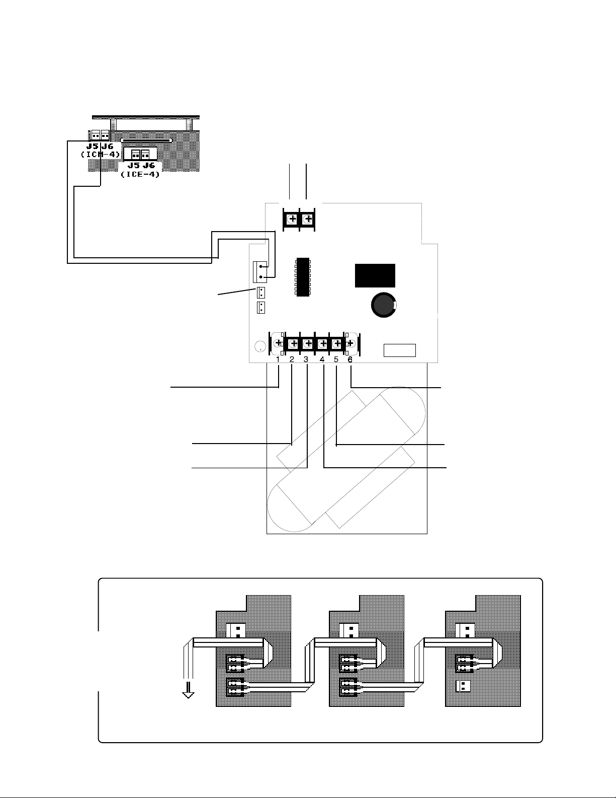
Figure 5-5 Field Wiring of the Optional Audio Visual Power Supplies (AVPS-24F/
AVPS-24FE)
24 VDC Bell Power
Unfiltered, unregulated, power-limited (3.0 amps max). Use Auxiliary
Bell Power Harness to provide power to notification circuit modules
(connect to J5 on IC-4F or ICE-4F).
+ -
1 2
Auxiliary Bell
Power Harness
Black wire
Blue wire
For the first or only A VPS-24F in a Sensiscan
2000, connect the AVPS-24F Trouble Cable
(71033) to P5 on the MPS-24AF or P4 on the
MPS-24BF for supervision. Otherwise connect as illustrated below.
P3
Trouble
LED
TB2
TB1
Earth Ground In
Connect to chassis or Earth
Ground Terminal on the
main power supply.
Secondary Power
(24 VDC Batteries)
Connect to:
MPS-24AF: TB2-1 (+) and TB2-2 (-)
MPS-24BF: TB3-1 (+) and TB3-2 (-)
For multiple
Audio Visual
Power Supplies
Earth Ground Out
Connect to TB1 Terminal 1
on next AVPS-24F.
+
-
Hot
Neutral
Primary Power
120 VAC for AVPS-24F
220/240 VAC for AVPS-24FE
MPS-24AF: TB1-5 (Neutral) and TB1-7 (Hot)
MPS-24BF: TB1-3 (Neutral) and TB1-4 (Hot).
Connect to:
36
To P5 on MPS-24AF;
or to P4 on the MPS24BF.
Last AVPS-24FFirst AVPS-24F
S2000 15017 Rev H 10/08/96 P/N 15017:H
Page 37

THE R45-24/R45-24E REMOTE BATTERY CHARGER
When the secondary requirements demand batteries that cannot be adequately charged by the main power supply employed,
an R45-24 Remote Battery Charger must be used. The R45-24 mounts in its own cabinet, up to 20 feet away (must be in the
same room as the control panel). The R45-24 is capable of charging 55 AH PS-12550 batteries, which are also contained in
the charger cabinet. For more information refer to the R45-24 Product Installation Drawing packaged with each unit.
CONNECTING THE PRIMARY POWER SOURCE
The R45-24 requires 120 VAC, 50/60 Hz primary power and the R45-24E requires 220/240 VAC, 50/60 Hz primary power.
With the breaker at the main power distribution panel turned off, connect the primary Hot line to Terminal 1 on the R45-24
and the primary Neutral line to Terminal 2. All connections between the Sensiscan 2000 and the R45-24 must be made in
conduit, using #12 AWG wire. Do not route VAC wiring in the same conduit as other Sensiscan 2000 circuits. Leave the
main power breaker off until installation of the entire system is complete.
CONNECTING THE SECONDARY POWER SOURCE (24VDC)
Do not connect AC power or batteries until the system is completely wired and ready for testing. Refer to Wiring Diagram
and instructions for the Fire-Lite R45-24 remote Battery Charger.
24 VDC. (supervised). Maximum charge current for standby batteries is 2 amps
Primary Power Sour ce
Hot Neutral
(fast charge) or 20mA (trickle charge). Use #12 AWG wire in conduit (20 feet or
less, in same room).
-
+
1 2 3 4
+ -
R45-24
MPS-24AF MPS-24BF
- +
PS-12550
12 VDC
55-AH
Battery
- +
PS-12550
12 VDC
55-AH
Battery
PS-12550
Battery
PS-12550
Battery
IMPORTANT!
1) Cut JP1 to disable on-board charger on the MPS-24AF.
2) Cut JP2 to disable on-board charger on the MPS-24BF.
TB2-2
TB2-1
Figure 5-6 Connecting the R45-24 Remote Battery Charger
TB2-6
TB2-5
S2000 15017 Rev H 10/08/96 P/N 15017:H
37
Page 38

SECTION SIX: APPLICATIONS
6.1 WATERFLOW ALARM
A waterflow alarm device may be connected to an IZ Series Initiating Zone Module circuit provided that the circuit is
programmed to activate at least one notification appliance circuit and one of the following conditions are met:
The initiating Device Circuit is programmed for waterflow operation
OR
the notification appliance circuit is programmed as non-silenceable.
6.2 SUPERVISORY SERVICE
Normally open supervisory devices may be connected to any Initiating Zone Module circuit provided that the circuit is
programmed for supervisory operation. This circuit must be dedicated to supervisory devices.
6.3 CENTRAL STATION
The Sensiscan 2000 can be employed as a protected premises Control Unit when used in conjunction with a compatible,
UL- listed electrically-activated transmitter or when used in conjunction with a compatible, UL-listed digital alarm communicator such as the 911A. (See Figure 6-1)
6.4 DIGITAL ALARM COMMUNICATOR TRANSMITTERS (DACT)
The Fire Alarm Control Panel (FACP) will support a Digital Alarm Communicator Transmitter (DACT) provided that the
panel is configured and programmed for DACT operation. Software P/N 73452 (or higher) will support DACTs that are
activated via relay contacts (911A), while Software P/N 73611 (or higher) will support the UDACT-F via the EIA-485
Annunciator Port.
The FACP must be programmed for DACT operation (see the Extended Programming Section). Programming the FACP for
DACT operation will delay the reporting of an AC loss condition for approximately eight hours (Software P/N 73452 or
higher) and modify the EIA-485 Annunciator Port protocol (Software P/N 73611 or higher) for UDACT-F operation.
The modified protocol is compatible with the AFM and LDM Annunciators. Annunciators and a UDACT-F can be connected to the EIA-485 Annunciator Port simultaneously. However, the modified EIA-485 protocol alters the assignment of
the first eight yellow annunciator LED's as shown in the table on the following page.
38
S2000 15017 Rev H 10/08/96 P/N 15017:H
Page 39

Annunciators and a UDACT-F can be connected to the EIA-485 Annunciator Port simultaneously. However, the modified
EIA-485 protocol alters the assignment of the first eight yellow annunciator LEDs as follows:
elbuorT
tnioP
wolleY(
)DEL
1elbuorTmetsyS
N/PerawtfoS
dna25437
rewol
tuohtiW
F-TCADU
elbuorTmetsyS
)ssolCAssel(
rehgihdna11637N/PerawtfoS
F-TCADUhtiW
elbuorTmetsyS
)ssolCAssel(
2decneliSlangiSdecneliSlangiSdecneliSlangiS
3desUtoNdesUtoNdesUtoN
4yrosivrepuSyrosivrepuSyrosivrepuS
5
6
7
tiucriCgnitacidnI
elbuorT1
tiucriCgnitacidnI
elbuorT2
eiTlapicinuM
elbuorT
tiucriCgnitacidnI
elbuorT1
tiucriCgnitacidnI
elbuorT2
eiTlapicinuM
elbuorT
tiucriCgnitacidnI
elbuorT1
tiucriCgnitacidnI
elbuorT2
dnG/yrettaBwoL
tluaF
8elbuorTlenaPliaFCAliaFCA
The FACP must be programmed for an annunciator whenever it's connected to a UDACT-F since the UDACT-F receives the
FACP status on the EIA-485 Annunciator Port. If the FACP is connected to both annunciators and a UDACT-F, all devices
except one must be configured as receive only. Refer to the table below for configuration and supervision arrangements.
seciveD
dellatsnI
F-TCADU
ylnO
F-TCADU
dna
rotaicnunnA
noitarugifnoCnoisivrepuSnoitarugifnoCnoisivrepuS
ylnOevieceR
F-TCADU)1etoN(rotaicnunnA
timsnarT/evieceR584-AIEaiV
timsnarT/evieceR584-AIEaiV
F-TCADUaiV
liaFmmoC
timsnarT/evieceR584-AIEaiV
1sserddA
ylnOevieceR
1sserddA
)2etoN(tuptuO
timsnarT/evieceR
1sserddA
ylnOevieceR
desivrepuS-nU
584-AIEaiV
584-AIEaiV
)3etoN(
1) Additional annunciators may be employed in the Receive Only Mode. The wiring to these annunciators will be
supervised only if the power and the EIA-485 circuits are wired sequentially and the Receive/Transmit device is
connected last.
2) The UDACT-F's Comm Fail Output (TB3, pin #2) must be connected to the AUX Trouble Input on the main power
supply (P5, pin #1 on MPS-24AF or P4, pin #1 on MPS-24B). See connection diagrams.
3) The power and the EIA-485 circuits are wired sequentially (the FACP connects to the annunciator and the annunciator connects to the UDACT-F).
S2000 15017 Rev H 10/08/96 P/N 15017:H
39
Page 40
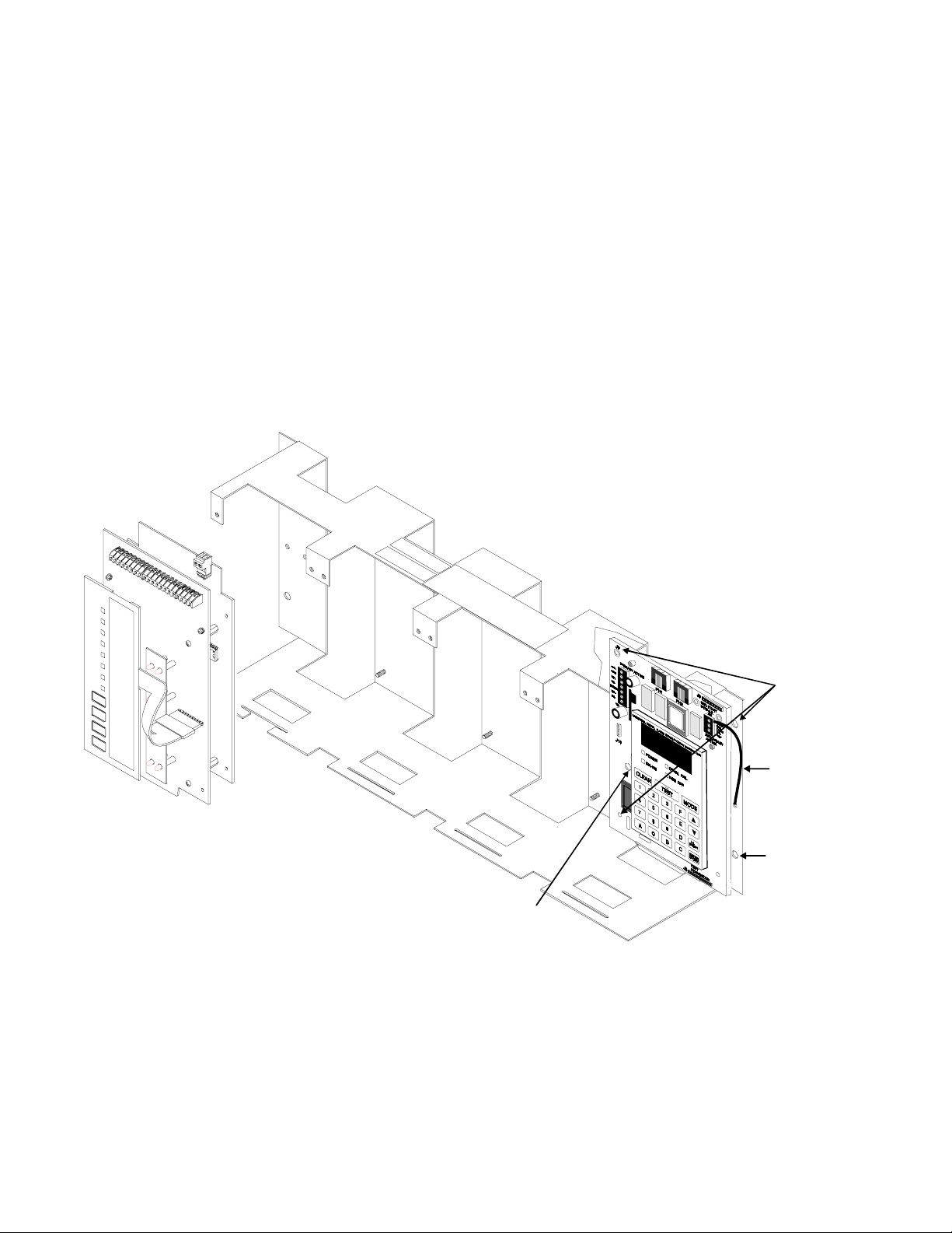
INSTALLING THE UDA CT-F
Remove all power from the control panel by disconnecting AC and batteries. Install the three supplied nylon support posts
for the top and bottom left of the UDACT-F, one aluminum/nylon and one aluminum standoff in the CHS-4 chassis slot in
which the UDACT-F is to be installed (refer to Figure 6-1). Position the UDACT-F on the standoffs and secure on aluminum standoff with a #6-32 screw. Alternatively, the UDACT-F may be mounted remotely using an ABS-8RF enclosure.
Ferrite cores are required for this application. Refer to the UDACT-F Manual, Document 50049 for more information.
Connect the communication line between the EIA-485 terminal block on the CPU-2000 and TB1 terminals 3 and 4 on the
UDACT-F being certain to observe polarity (refer to the Document 50049). Recommended wire is 12 AWG to 18 AWG
twisted pair. If no other devices are connected to the EIA-485, install a 120 ohm end-of-line resistor across UDACT-F TB1
terminals 3 and 4.
Connect the supplied Ground Strap from the UDACT-F Earth Ground terminal on TB3 to the CHS-4 chassis. Connect
24VDC filtered, regulated, non-resettable power to TB1 terminals 1 and 2 on the UDACT-F (refer to Document 50049).
CPU-2000
CHS-4
Aluminum Standoff
and screw
Figure 6-1: UDACT-F Mounting in CHS-4
UDACT-F
Nylon
Support
Posts
Ground
Strap
Nylon &
Aluminum
Standoff
40
S2000 15017 Rev H 10/08/96 P/N 15017:H
Page 41

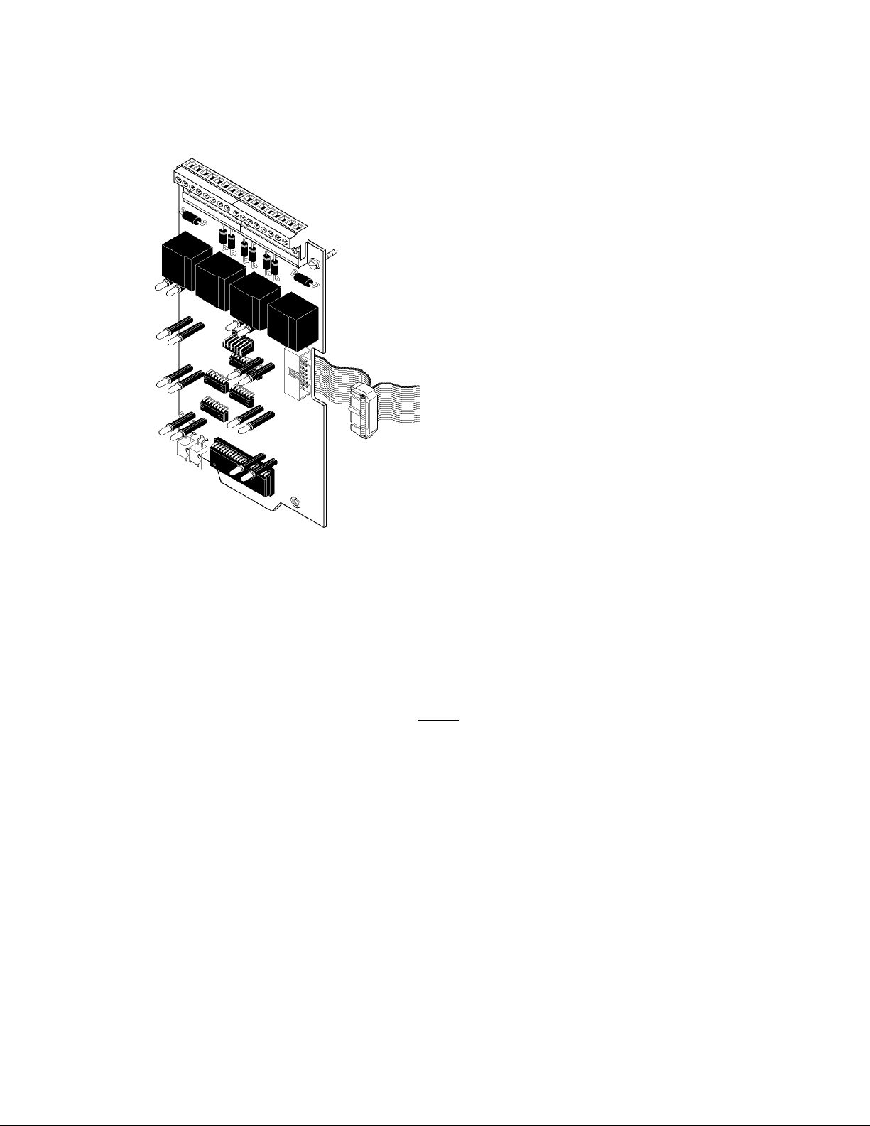
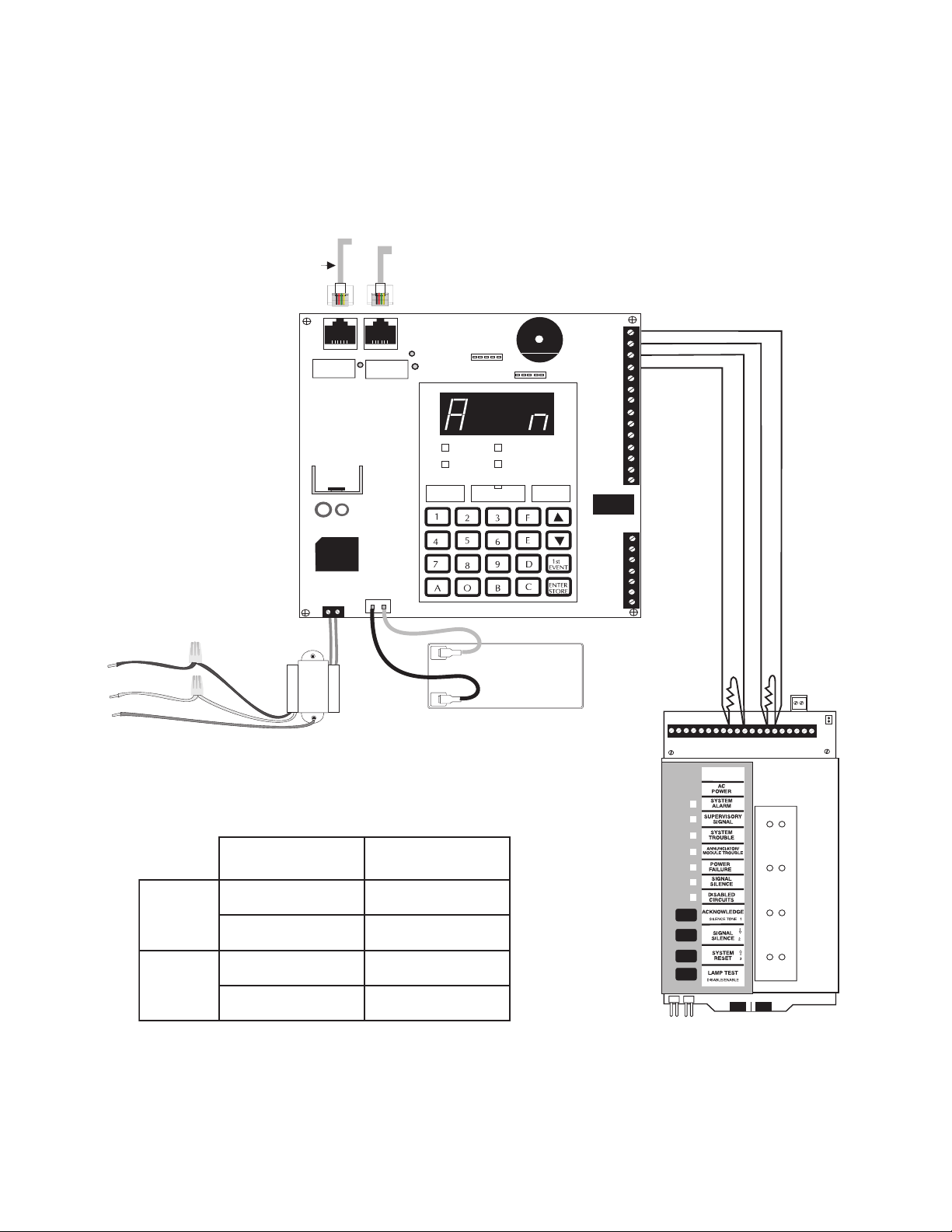
6.5 CONNECTION OF A 911A DIGITAL COMMUNICATOR
The Noti-Fire 911A Digital Alarm Communicator Transmitter (DACT) is a three-zone module designed for use with the
Sensiscan 2000 to provide for off-premises monitoring of this fire alarm control panel. For stand-alone installations, use the
911AC kit that includes a transformer and an enclosure(s) for both the 911A and the transformer. The 911A is self-powered
in this mode and is triggered by the alarm and/or trouble contacts received from the control panel. It communicates with a
digital receiver by means of one of two transmission formats, BFSK or Pulsed Fast Single Round format.
Power Requirements: 26.6VDC minimum, 30 mA in Normal; 138 mA while communicating; 166.8 mA with alarm &
trouble relays while communicating.
Retard time and Reset time must be programmed for zero second when connecting the alarm initiating circuit to an existing
control panel.
For more detailed instructions and connection and power information, refer to the Noti-Fire 911A manual, Document #7406200-005-A.
Trouble
Common
(+) 24 VDC
(+) 27.6 VDC
CPU
Alarm
911A
Wiring between the F A CP
and 911A must be in conduit.
mralA
yllamron
nepo
stcatnoc
elbuorT
yllamron
nepo
stcatnoc
CDV42+
nommoC
UPCA119SPM
41-1BT7dna6
51-1BT9dna8
9-1BT01
11-1BT11
23-2BT
44-2BT
MPS-24AF
S2000 15017 Rev H 10/08/96 P/N 15017:H
41
Page 42
6.6 MS-5012 AS A DAC T
Secondary
CPU
The MS-5012 may be used as a slave communicator to a master FACP. In slave configuration, five channels may be
triggered by the relay outputs of the master panel. Zone 1 is used for General Alarm, Zone 2 is used for general trouble, Zone
4 is used for supervisory. Zone 3 and 5 may be programmed to match the FACP relay function.
Phone Line
Modular Cable
P/N MCBL-6
Primary
Phone Line
120 VAC
HOT
Neutral
Ground
White
Green
Black
yellow
1 2
Primary
Active
yellow
Black
Secondary
Active
J2
Kissoff
AC POWER TROUBLE
ALARM
RESET SILENCE MODE
Red
+
-
J3
SUPERVISORY
12VDC
Battery
2-7AH
TB2
1
2
3
4
5
6
7
8
9
10
11
12
13
14
Alarm
Trouble
TB3
12
9
10 1112 1314 1516171819 20
56
4
3
78
TB1
AC wiring for the DACT/FACP
must be connected to the same
circuit.
2105-SMdraobrehtoM
1-2BT51-1BT
mralA
2-2BT41-1BT
3-2BT01-1BT
elbuorT
4-2BT9-1BT
NOTES:
1) Reference the MS-5012 manual for additional information.
2) Program the MS-5012 for slave application.
Figure 6-2A: Connecting the MS-5012 as a DACT
42
S2000 15017 Rev H 10/08/96 P/N 15017:H
Page 43

Figure 6-3: Transmitter Connections
Sensiscan 2000
CPU-2000
Form C Alarm contact programmed
to activate on General Alarm.
Form-C Trouble contact which will
automatically activate on any Trouble
condition.
6.7 PROPRIETARY PROTECTIVE SIGNALING
The Sensiscan 2000 can be employed as a Proprietary Protective Premises Control Unit when used in conjunction with a
compatible, UL-listed receiving unit.
1) Connection between Sensiscan 2000 and the transmitter is supervised by the transmitter.
2) Use transformer mode ULT STK NO. 100391 (listed, Class 2, 12 V, 10VA.). See Potter Electric Signal
Company Bulletin #748.
3) This Sensiscan 2000/Transmitter arrangement can be employed for an NFPA 72-1993 Central Station Fire Alarm
System, NFPA 72-1993 Remote Station Fire Alarm System, or NFPA 72-1993 Proprietary Fire Alarm System.
S2000 15017 Rev H 10/08/96 P/N 15017:H
43
Page 44

6.8 TEE-TAPPING
One Tee-Tap will be allowed on Style Y notification appliance circuits if a 10 K End-of-Line Resistor (Part # 71274) is used
on each branch as shown in Figure 6-4. Note: This application is not recommended by Factory Mutual (FM).
Listed
4.7K ELR
(Part # 71252)
10K ELR
(Part # 71274)
T ee-Tapped
Notification Appliance
Circuit
Standard
Style Y
Listed
10K ELR
(Part # 71274)
44
IC-4F Notification Circuit
Module or ICE-4F Expander
Figure 6-4: Tee-Tapping Notification Appliance Circuits
S2000 15017 Rev H 10/08/96 P/N 15017:H
Page 45
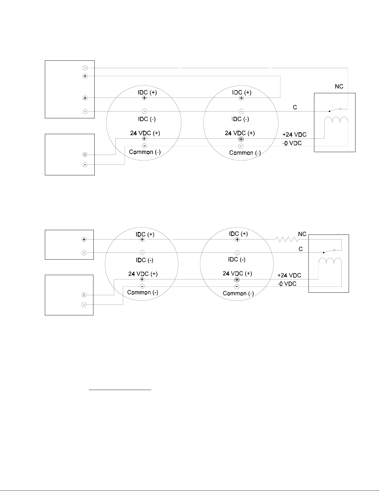
6.9 FOUR-WIRE SMOKE DETECTORS
Initiating devices requiring 24 VDC operating power can be wired as illustrated in Figures 6-4 and 6-5.
IZ Series
Initiating Device
Circuit
24VDC Power
Supply
Power-limited,
UL listed for Fire
Protective
Signaling
UL-listed 24 VDC
Four-Wire Smoke Detectors
UL-Listed Power
Supervision
Relay
MPS-24AF TB3 Term. 1 (+) & 2 (-)
MPS-24BF TB2 Term. 1 (+) & 2 (-)
Figure 6-4:
Employing Four-Wire Smoke Detectors (Style D)
All connections are supervised and power-limited
4.7K 1/2-watt EndOf-Line Resistor,
IZ-4F or
IZ-8F
Initiating Device
Circuit
24VDC Power
Supply
Power-limited,
UL listed for Fire
Protective
Signaling
MPS-24AF TB3 Term. 1 (+) & 2 (-)
MPS-24BF TB2 Term. 1 (+) & 2 (-)
Figure 6-5: Employing Four-Wire Smoke Detectors (Style B)
UL-listed 24 VDC
Four-Wire Smoke Detectors
All connections are supervised and power-limited
Notes on Style B and Style D field wiring:
1) The Power Supervision Relay coil leads must be connected to the last detector base 24V screw terminal.
2) Calculation of the maximum allowable resistance in the 24VDC detector power wiring:
Part #71245
UL-Listed Power
Supervision
Relay
RMAX = (20.6 - VOM)
where:
(N)(IS) + (NA)(IA) + (IR)
RMAX is the maximum total resistance of the 24V power circuits.
VOM is the minimum operating voltage of the detector or end of line relay, whichever is greater, in volts.
N is the total number of detectors on the 24V supply loop.
IS is the detector current in standby.
NA is the number of detectors on the 24V power loop which must function at the same time in alarm.
IA is the detector current in alarm.
IR is the end-of-line relay current.
S2000 15017 Rev H 10/08/96 P/N 15017:H
45
Page 46
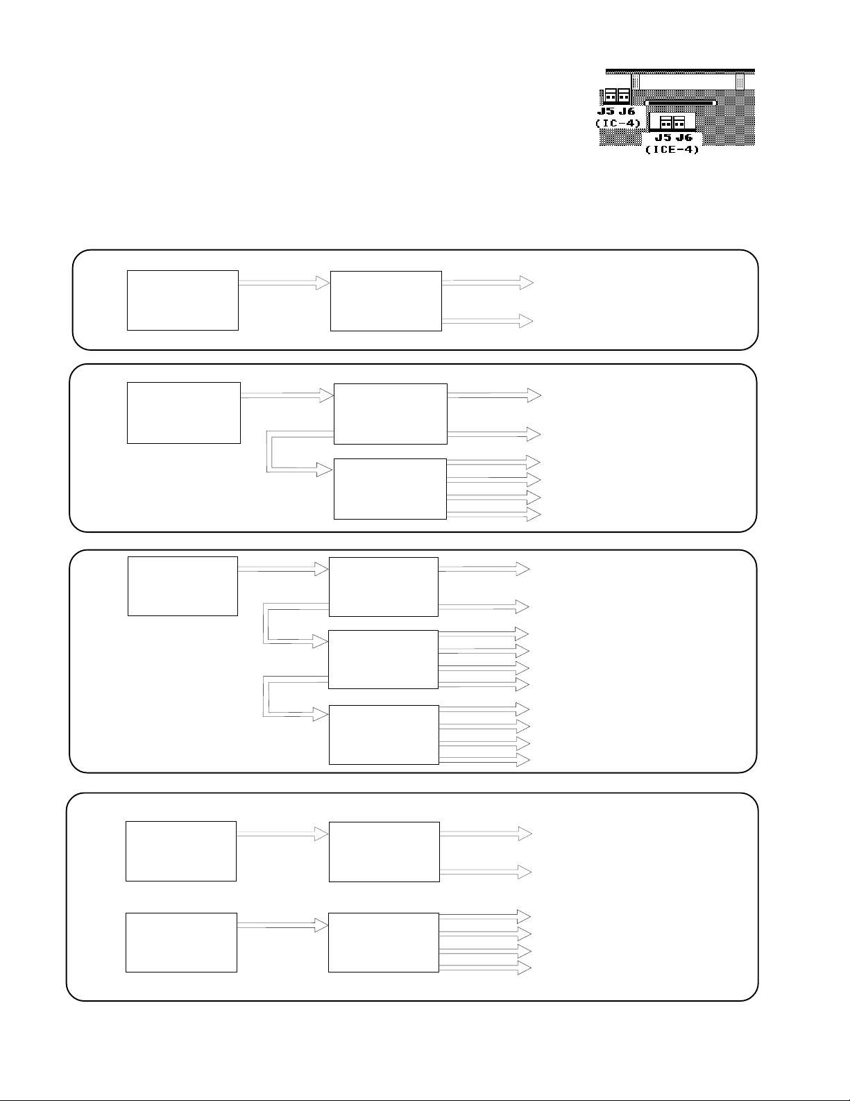
6.10 NO TIFICATION APPLIANCE CIRCUIT POWER CONFIGURATIONS
The total current drawn from a notification appliance circuit cannot exceed 3.0 amps (subject
to the limitations of the power supply). Figure 6-6 illustrates some of the typical power
supply/notification appliance circuit configurations possible with the Sensiscan 2000.
Figure 6-6: Typical Supply/Notification Circuit Configurations
J5
main
power
supply
main
power
supply
CPU
Module
J5
CPU
Module
J6
J5
IC-4F
These two notification appliance circuits share the total main power
supply current.
These six
Notification appliance
circuits share the total main
power supply current.
Bottom view of the
IC-4F/ICE-4F
main
power
supply
main
power
supply
AVPS-24F
J5
J6
J5
J6
J5
J5
J5
CPU
Module
IC-4F
ICE-4F
CPU
Module
IC-4F
These ten
Notification appliance
circuits share the total main power
supply current.
These two notification appliance circuits share the total
main power supply current.
These four notification appliance circuits share the total
3.0 amps of current on the
AVPS-24F.
46
S2000 15017 Rev H 10/08/96 P/N 15017:H
Page 47
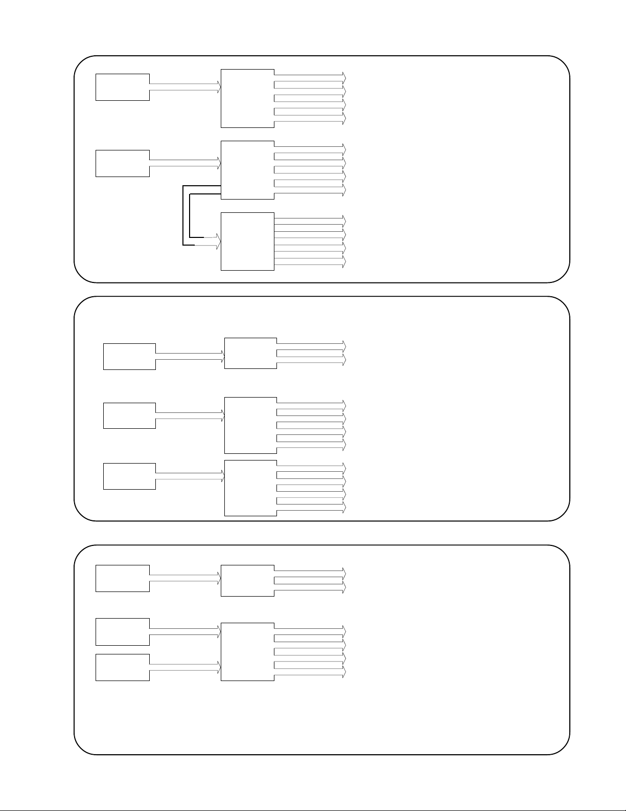
A VPS
J5
IC-4F
These four notification appliance circuits share 3.0 amps of one AVPS24F.
A VPS
Main
Power
Supply
A VPS
J5
IC-4F
J6
J5
ICE-4F
J5
Module
J5
IC-4F
CPU
These eight notification appliance circuits share 3.0 amps of one AVPS24F.
These two notification appliance circuits share 3.0 amps of one AVPS24F.
These four notification appliance circuits share 3.0 amps of one AVPS24F.
A VPS
J5
IC-4F
J5
Main
Power
CPU
Module
Supply
A VPS
J5
IC-4F
A VPS
J6
Whenever supplying an IC-4F or ICE-4F module with
two different sources of power (as in the abo ve illustration), cut jumper JP1 and JP2.
S2000 15017 Rev H 10/08/96 P/N 15017:H
These four notification appliance circuits share 3.0 amps of one AVPS24F.
These two notification appliance circuits share total current of the main
power supply.
These two circuits share 3.0 amps
of one A VPS-24F.
These two circuits share 3.0 amps
of one A VPS-24F.
47
Page 48

6.11 REMOTE COMMAND INPUTS FOR THE SENSISCAN 2000
The function of Acknowledge, Signal Silence, and Reset can be executed from remote switches. The switches are wired to
IZ-8F circuits which must be programmed for this special operation. Additional functions are outlined below, can also be
accomplished through IZ-8F circuits.
Presignal Inhibit: IZ-8F zone 1. Program zone as non-alarm and supervisory. This command is used to inhibit presignal
operation. Upon entering presignal, the CPU checks zone 1 on all IZ-8F modules. If the zone is active (shorted), all presignal
or PAS operations will be ignored.
Emergency Alert: IZ-8F zone 5. Program zone as non-alarm and supervisory. Use as an evacuation signal for tornados,
bomb-scares and other non-fire emergency situations. If the control panel is not in alarm, activation (short) on zone 5 will
activate all notification appliance circuits and output relays, that are mapped to zone 5, with a steady signal. Programmed
March Time or Temporal code is ignored. A fire alarm will take priority over an emergency alert. Notification appliance
circuit used for fire must be programmed for MTC or Code 3 operation. Emergency Alert is for local signalling only, do not
map to "Remote Signalling/Municipal Tie" outputs.
Acknowledge: IZ-8F zone 6. Program circuit as non-alarm and supervisory. Use to remotely execute an Acknowledge
command without the need of an AFM-16ATX annunciator.
Signal Silence: IZ-8F zone 7. Program circuit as non-alarm and supervisory. Use to remotely execute the Signal Silence
command without the need of an AFM-16ATX annunciator.
System Reset: IZ-8F zone 8. Program circuit as non-alarm and supervisory. Use to execute the Reset function without the
need of an AFM-16ATX annunciator.
Presignal
Inhibit
Function only as
regular Alarm
zones
Figure 6-7: Remote Command Input Connections
Emergency
Alert
Acknowledge
Signal
Silence
Reset
1) Initiating circuits used as command circuits are supervised, power-limited, and may be connected to limited-energy cable.
2) Maximum line resistance allowed due to wiring is 100 ohms.
48
S2000 15017 Rev H 10/08/96 P/N 15017:H
Page 49
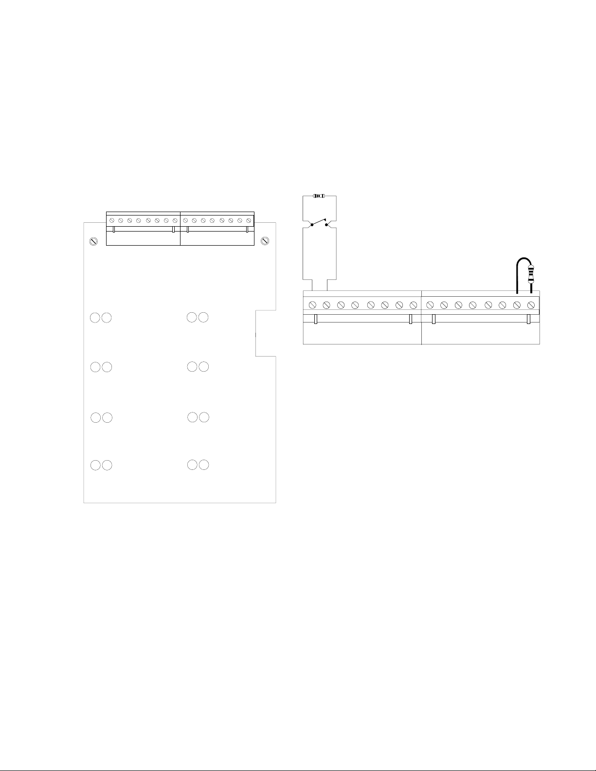
Figure 6-8: Remote Presignal Inhibit, Emergency Alert,
Acknowledge, Signal Silence and System Reset Switches (Style B).
ABCDEFGH
ññ ññ ññññ
B+ B- B+ B- B+ B- B+ B- B+ B- B+ B- B+ B- B+ B-
4.7K ELR
P/N 71252
Presignal Inhibit
Switch
IZ-8F
B+ B-
Dummy load all unused
circuits with 4.7K ELR,
Part # 71245
A
Presignal Inhibit
B
(standard zone)
C
(standard zone)
D
(standard zone)
E
Emergency Alert
F
Acknowledge
G
Signal Silence
H
System Reset
1) Switches used to control Presignal Inhibit, Acknowledge,
Signal Silence or System Reset must be key operated,
located within a locked cabinet, or arranged to provide
equivalent protection against unauthorized use.
2) Switches must be UL listed to switch 30 VDC at 50mA.
3) If a key operated switch is used, the key should be re-
movable in both open and closed positions, when used
for Presignal Inhibit. The keys should be removable in
the open position only when used for Acknowledge, Signal Silence or System Reset.
4) The Presignal Inhibit, Emergency Alert, Acknowledge,
Signal Silence or System Reset functions can be controlled
by a relay contact from a CR-4F/CRE-4F Relay Module,
which can be operated from switches on AFM-16ATX
Annunciators.
5) Locate Acknowledge, Signal Silence and System Reset
switches adjacent to a system annunciator so that system
status is available to the operator.
6) Remote Command Circuits are supervised and power limited. Maximum wire resistance per circuit is 100 ohms.
Circuits wired for Style B operation require a 4.7K EndOf-Line Resistor (P/N 71252) at the end of the line.
S2000 15017 Rev H 10/08/96 P/N 15017:H
49
Page 50

Figure 6-9: Remote Presignal Inhibit, Emergency Alert,
Acknowledge, Signal Silence and System Reset Switches (Style D).
12 345678
сс сссссс
A+ A- A+ A- A+ A- A+ A- A+ A- A+ A- A+ A- A+ A-
B+ B- B+ B- B+ B- B+ B- B+ B- B+ B- B+ B- B+ B-
Style D
Presignal Inhibit
Switch
Jumper all unused
circuits as shown
IZ-8F
A+ A-
IZE-8F
1
Presignal Inhibit
2
(standard zone)
3
(standard zone)
4
(standard zone)
5
Emergency Alert
6
Acknowledge
7
Signal Silence
8
System Reset
B+ B-
IZ-8F
Switches used to control Presignal Inhibit, Acknowledge, Signal Silence or System Reset must be key operated, located
within a locked cabinet or arranged to provide equivalent protection against unauthorized use.
1) Switches must be UL-listed to switch 30 VDC at 50mA.
2) If a key operated switch is used, the key should be removable in both open and closed positions when used for
Presignal Inhibit. The keys should be removable in the open position only when used for Acknowledge, Signal
Silence or System Reset.
3) The Presignal Inhibit, Emergency Alert, Acknowledge, Signal Silence or System Reset functions can be controlled
by a relay contact from a CR-4F/CRE-4F Relay Module, which can be operated from switches on AFM-16ATX
Annunciators.
4) Locate Acknowledge, Signal Silence and System Reset switches adjacent to a system annunciator so that system
status is available to the operator.
5) Remote Command Circuits are supervised and power limited. Maximum wire resistance per circuit is 100 ohms.
50
S2000 15017 Rev H 10/08/96 P/N 15017:H
Page 51

SECTION SEVEN: PROGRAMMING
7.1 GENERAL
The control panel is programmed entirely by using the four switches on the CPU. The eight LEDs are used to show the
programmer the status of programming. Each of these LEDs has two states - flashing and steady. On the programming label,
two functions are associated with each LED. The function marked with an "F" is indicated by a flashing LED. The function
marked with a "S" is indicated by steady LED illumination.
7.2 PREPARING FOR PROGRAMMING
Slide programming label into the Dress Panel. Insert the Programming Key through the dress panel into Plug J11 on the
CPU. Wait until ENTER PASSWORD LED and PRESS ENTER LED flash, then enter password.
7.3 ENTERING PASSWORDS
There are four different programming modes, each with its own password. They are as follows:
Reconfigure: 123-1231, System Programming: 123-1232, Extended Features: 123-3211, Clear Program 312-1233
After entering the appropriate password digits, press the ENTER switch.
7.4 CLEAR PROGRAM (P ASSWORD 312-1233)
Before reconfiguring the system, we recommend clearing the CPU's memory. To do this use the PROGRAM CLEAR
function. After PREPARING FOR PROGRAMMING enter the password 312-1233 then press and hold the ENTER key.
The LEDs on the modules will go through a scrolling sequence until finally only the ENTER PASSWORD and PRESS
ENTER LEDs are lit (approx. 10 sec.). PROGRAM CLEAR is now complete and the system is ready for reconfiguration.
NOTE: Program clear should only be executed on new systems or ones that have been significantly changed because all
previous programming will be removed!
7.5 RECONFIGURE MODE (PASSWORD 123-1231)
Upon entering the Reconfigure Mode, the CPU identifies what modules are in the system. The system must be reconfigured
the first time it is programmed and any time a module is removed or added. The Reconfigure Mode sets new modules to the
default conditions listed below (the program for modules that have been previously reconfigured remains unchanged)
No circuits are selected for waterflow, supervisory, or circuit verification.
No circuits are selected for coded output. All notification appliance circuits are silenceable.
Control relays are non-silenceable. All circuits are mapped for general alarm.
After entering the Reconfigure password and pressing CHANGE STATE key, the PASSWORD ACCEPTED LED and the
RECONFIGURE LED will illuminate. All correctly-installed modules will light their LEDs as follows:
IZ-8F: All red and yellow LEDs
IZ-4F: All red and yellow LEDs
IC-4F, ICE-4F: Four green LEDs on left. All eight will light if an expander has been installed.
CR-4F, CRE-4F: Four yellow LEDs on left. All eight will light if an expander has been installed
TC-2F, TC-4F: All eight green LEDs will light.
Press the ESCAPE switch to store the system configuration. Programming will advance to programming of the system.
Access Security
Additional access security for the system
can be obtained by setting a switch on
the lower CPU board to the Write Inhibit
position. When set to the Write Inhibit
position, the system will still give the
impression that it can be programmed,
but pressing the ENTER key will not result in the storing of any program data
all work will be lost.
Note: The panel's Disable feature will not function with Write Inhibit selected.
S2000 15017 Rev H 10/08/96 P/N 15017:H
The Security Switch can
be found in one of two
locations on the CPU.
Write Enable
position
Write Inhibit
position
51
Page 52

7.6 SYSTEM PROGRAMMING (PASSWORD 123-1232)
System programming may be entered directly by password or is automatically entered after reconfiguring the panel (by
pressing the Escape key).
After entering the system programming password , the green PASSWORD ACCEPT LED and the yellow PROGRAM/
SERVICE LED will illuminate. Programming of the system is performed sequentially. The first function to be programmed
is WATERFLOW.
WATERFLOW OPERATION
Notification appliance and other output circuits that
are activated in response to an alarm on a waterflow
initiating circuit cannot be silenced by the Signal
Silence switch.
Programming Waterflow Circuits
The WATERFLOW LED will flash to indicate the
Sensiscan 2000 is ready to be programmed for
waterflow circuits.
A flashing yellow initiating circuit LED serves as
the printer. It shows the programmer what circuit
is being programmed at that time. Press the STATE
CHANGE switch to select or deselect this circuit.
Pressing the POINT SELECT A switch advances
the pointer to the next initiating circuit. Pressing
the POINT SELECT B switch moves the pointer to
the previous initiating circuit.
When all waterflow circuits have been selected,
press the FUNCTION SELECT switch to store the
WATERFLOW programming information and advance programming to the next function - SUPERVISORY.
SUPERVISORY OPERATION
Activation of a device on a circuit programmed for supervisory will light the supervisory LED. The system trouble LED and
the system trouble outputs will not be activated. Supervisory circuits can be mapped to controlled outputs. Circuits can
detect the difference between the normally open supervisory switch and a break in the field wiring.
Programming Supervisory Circuits
The Supervisory LED will illuminate steadily on the CPU. The pointer LED will be at the first initiating circuit. Use the
STATE CHANGE switch to select or deselect that circuit for supervisory. The POINT SELECT switches move the pointer
to the other initiating circuits.
When all Supervisory circuits have been programmed, press the FUNCTION SELECT switch to store the programming
information and advance programming to the next function SILENCEABLE.
52
S2000 15017 Rev H 10/08/96 P/N 15017:H
Page 53

SILENCEABLE OPERATION
Silenceable circuits are controlled output circuits that, when activated, can be silenced by pressing the signal silence key on
the CPU. Do Not program the Remote Signalling / Municipal Tie output for silenceable operation.
Programming Silenceable Circuits
The SILENCEABLE LED will flash on the CPU. The pointer is represented by a flashing yellow LED on the first output
circuit. Use the STATE CHANGE switch to select or deselect the circuit for silenceable operation. The green LED will
illuminate when the circuit has been selected as silenceable. Use the POINT SELECT switches to move the pointer to the
other output circuits.
When all silenceable circuits have been programmed, press the FUNCTION SELECT switch to store the programming
information and advance programming to the next function CODED CIRCUITS.
CODED CIRCUIT OPERATION
Selecting controlled outputs for coded operation enables those outputs to pulse a selected code chosen later in the programming process (see code type). Outputs that are not selected for coded operation will turn on steady.
Programming Coded Circuits
The CODED CIRCUIT LED will illuminate steadily on the CPU. The pointer will be at the first output circuit. Use the
STATE CHANGE switch to select or deselect the circuit for coded operation. Use the POINT SELECT switches to move
the pointer to the other output circuits.
When all coded circuits have been selected, press the FUNCTION SELECT switch to store the programming information
and advance programming to the next function CODE TYPE.
CODE TYPE SELECTION
Allows for the selection of March Time Code (110 beats per minute) or Temporal (3-3-3) coding for circuits programmed as
coded in the previous step. Code type selection is on a system basis, therefore all coded circuits will sound the same code.
Circuits that were not selected as coded are unaffected by Code Type selection.
Special Requirements apply to codes and code type selection when the system employs a TC-2F or TC-4F module. See the
TC-2F Manual and the TC-4F Manual for more information
Programming Code Type
The CODE TYPE LED flashes. Use the STATE CHANGE switch to chose between the two codes:
Green LED for notification appliance circuit 1 on-Temporal
Yellow LED for notification appliance circuit 1 on-March Time
When code type is programmed, press the FUNCTION SELECT switch to store the programming information and advance
the programming to the next function VERIFIED ZONES.
Code Type
Temporal
March Time
Verified / PAS
VERIFIED/PAS
Alarm Verification increases the time required to initiate an alarm from two wire smoke detectors. When the system detects
an alarm on an initiating circuit programmed for verification, it will automatically reset the power to that circuit. Power is
then reapplied, beginning a verification period. Any alarm detected during this period will initiate an immediate system
alarm.
Verification should only be used on circuits where false alarm rate cannot be reduced to an acceptable level by other means.
Only alarm signals from two-wire smoke detectors can be verified since four-wire smoke detectors are not reset during
verification. Both two-wire smoke detectors and normally-open shorting-type initiating devices may be connected to the
same circuit, although verification will not affect the contact type devices.
S2000 15017 Rev H 10/08/96 P/N 15017:H
53
Page 54

Positive Alarm Sequence (PAS)
PAS adds a 15 second, post-alarm delay to signal activation. Pressing the ACKNOWLEDGE or SILENCE key before 15
seconds has expired will change the timer to its full value (1, 2, OR 3 MINUTES) programmed.
For proper operation of PAS, the following conditions must be met:
1) The control panel must be located so that an alarm signal can be acknowledged by trained personnel
within 15 seconds.
2) The system must be equipped with a presignal bypass switch.
3) The system must be configured so that activation of a second automatic fire detector bypasses presignal
and immediately activates alarm signals. To accomplish this, the installer must install one smoke detector per
conventional initiating device.
4) Zones selected for PAS operation shall contain smoke detectors only. These zones may not contain other
initiating devices such as manual stations, heat detectors, waterflow indicators, etc.
A fire alarm system that fails to meet the above requirements for PAS service will be classified as a presignal system
only.
Programming Verified or PAS Zones
The VERIFIED / PAS LED will illuminate steady. The pointer will be at the first initiating circuit. Use the STATE
CHANGE switch to select or deselect the circuit for verification. Use the POINT SELECT switches to move the pointer
to the other initiating circuits.
When all VERIFIED / PAS ZONES are programmed press the FUNCTION SELECT switch to store programing information and advance programming to the next function NON ALARM INPUTS.
NON ALARM INPUTS
A non-alarm input is an initiating circuit that, upon activation, will not light the System Alarm LED or cause the piezo to
sound, will not latch, will self-restore and can be mapped to activate output circuits. Note: If the system is in alarm, or
enters an alarm condition, non-alarm inputs WILL latch. When a short circuit occurs on a non-alarm circuit, the IZ red
LED is turned on, but the System Alarm LED and the piezo sounder are not activated. Non-alarm points have a lower
priority compared to regular IZ alarm zones. Non-alarm circuits are "tracking" (non-latching) in that they turn on when
the circuit is shorted and turn off when the circuit returns to normal (unless the system is in alarm). Non-alarm circuits use
the I/O map capability of the control panel and the mapped controls simply turn on/off as the non-alarm point turns on/off.
Non-alarm circuits are supervised for opens.
Applications
Non-Alarm circuits are used to monitor devices that are not fire initiating sensors. Examples of these applications are:
Building HVAC and energy management sensors such as thermostats or timers could be connected to Non-Alarm
points and used to open/close ventilation dampers connected to CR-4F relays. In the event of a fire situation, the
control panel could force the dampers in one position or the other, and subsequent non alarm state changes would
be ignored.
A manual drill switch could be connected to an IZ point and used to manually test the alarm system without
causing a System Alarm or activating a Remote Station.
Door locks connected to CR-4F/CRE-4F modules could be unlocked when a fire is detected by the Sensiscan 2000.
A Non-Alarm point could be used to manually unlock/lock the doors in non-fire situations.
Programming Non-Alarm Inputs
The NON ALARM INPUTS LED will flash. The pointer will be at the first initiating circuit. Use the STATE CHANGE
switch to select or deselect the circuit as a Non Alarm Input. The left-hand LED (red) on each point will illuminate when
the circuit is selected, and will extinguish when the circuit has been deselected. Use the POINT SELECT switches to move
the pointer to the other initiating circuits. Press the FUNCTION SELECT switch to store this programming and proceed to
programming the next function ANNUNCIATOR INSTALLATION.
54
S2000 15017 Rev H 10/08/96 P/N 15017:H
Page 55

ANNUNCIATOR INSTALLATION
Annunciator installation programming allows the programmer to tell the panel if a serial annunciator has been installed.
Programming Annunciator Installation
The ANNUNCIATOR INSTALL LED will illuminate steadily. An illuminated green LED for notification appliance circuit #2 represents an installed annunciator. Use the STATE CHANGE switch to
select or deselect annunciator installation. After programming annunciator installation, press the FUNCTION SELECT key to store the programming information and advance programming to the next function.
Annunciators
None
Annun
SILENCE INHIBIT
The SILENCE INHIBIT function prevents the operation of the Signal Silence switch for 30 seconds,
60 seconds or 5 minutes after the output circuits have been activated.
Programming Silence Inhibit
The SILENCE INHIBIT LED will flash. Use the STATE CHANGE switch to select Silence
Inhibit time as represented by the Alarm Relay LEDs.
After programming Silence Inhibit press the FUNCTION SELECT switch to store this information and select the next function I/O Map.
INPUT/OUTPUT MAP
The I/O map is the assignment of output circuits to be activated by particular initiating circuits. Unmapped initiating circuits will not generate a
system alarm. Unmapped controlled outputs will not operate.
Programming the I/O MAP
The I/O Map LED will illuminate steadily. The red LED pointer will
illuminate steadily on the selected initiating circuit. A yellow flashing
LED points to an output circuit. Pressing the STATE CHANGE switch
will select or deselect the output circuit to be activated by the initiating
circuit. Use the POINT B SELECT to scroll through each of the output
circuits and the STATE CHANGE switch to select/deselect the outputs
(after scrolling through all of the output circuits it will cycle back to the
first).
Silence Inhibit
None
30 sec
60 sec
5 min
After each of the output circuits has been selected/deselected, press the
POINT A SELECT switch to move the red pointer to the next initiating
circuit. Continue mapping outputs for each initiating circuit.
After programming the I/O map, press the FUNCTION SELECT key to
store I/O map programmed. If you do not press the FUNCTION SE-
LECT switch after programming the I/O Map, the I/O map will not
be saved. Yellow LEDs on initiating circuits show unmapped circuits.
Press ESCAPE switch to return to I/O mapping, or ENTER switch to
return to Waterflow. Remove the Programming Key to exit programming mode.
Note
After the system has been programmed, the Programming Key
must be removed to transfer the programming information
from temporary memory storage to nonvolatile memory.
S2000 15017 Rev H 10/08/96 P/N 15017:H
55
Page 56

EXTENDED PROGRAMMING FEATURES (PASSWORD 123-3211)
The following features are available in CPU EPROM U4 software numbered 73265 (or greater).
The AUTO SILENCE feature will automatically turn off all silenceable circuits after a pre-programmed delay. The delay
timer starts after a system alarm. Any subsequent alarms which occur before the auto silence activates will restart the delay
countdown at zero.
The PRESIGNAL DELAY delays the activation of all silenceable circuits mapped to a zone in alarm for a pre-programmed
length of time. A subsequent alarm aborts the delay and re-maps all alarm points. Pressing the SIGNAL SILENCE switch
before the delay time has expired aborts the delayed activation of the silenceable circuits. Note: When Pre-Signal Delay
has been selected, at least one notification appliance circuit must be programmed as non-silenceable. This will
ensure that at least one notification circuit will sound immediately after initiation of an alarm condition.
The POSITIVE ALARM SEQUENCE (PAS) function adds a timer. After a first alarm, the timer is set for 15 seconds. If
nothing happens in that 15 seconds, all signals are activated. If an ACKNOWLEDGE or SILENCE key (including annunciator keys) is pressed before 15 seconds, the timer changes to its full value (1, 2, or 3 minutes).
Note: When Pre-Signal has been selected, at least one notification appliance circuit must be programmed as non-silenceable.
This will ensure that at least one notification Circuit will sound immediately after initiation of an alarm condition.
NFPA 72-1993 requires the installation of a Day/Night/Weekend switch that can override PAS operation. This can be
accomplished by using a normally open switch to close an IZ-8F that has been programmed for NON-ALARM and SUPERVISORY operation. Note that the zone cannot have a notification appliance circuit mapped to it.
The switch totally inhibits all presignal function. On entering presignal mode, the CPU checks zone 1 in module 1. If this is
an IZ-8F zone set for NON-ALARM and SUPERVISORY, and it is active (switch is on), all presignal and PAS operation
will be ignored.
AC LOSS REPORT DELAY When a Digital Alarm Communicator Transmitter (DACT) is used, the reporting of an AC
Loss condition must be delayed. With software P/N 73452 (or higher), this function can be selected under extended programming features. When selected, the CPU's trouble contacts will not be activated for loss of AC power until approximately 8 hours after loss of power occurs.
The CALIFORNIA CODE mode adds a ten second timer to the two notification circuits on the CPU. When an alarm
occurs, the timer is started. At the end of the ten second period, all silenceable circuits are shut off for five seconds. NOTE:
The circuits on the CPU and the circuits on the IC-4F are controlled by different microprocessors and may not be in
synchronization with each other. At the end of the five seconds, the circuits are turned on again for 10 seconds. This cycle
repeats indefinitely.
In the event of an acknowledged alarm, the REMINDER mode pulses the piezo every 15 seconds. If an acknowledged
trouble exists, but not an alarm, the piezo will beep every two minutes.
56
S2000 15017 Rev H 10/08/96 P/N 15017:H
Page 57
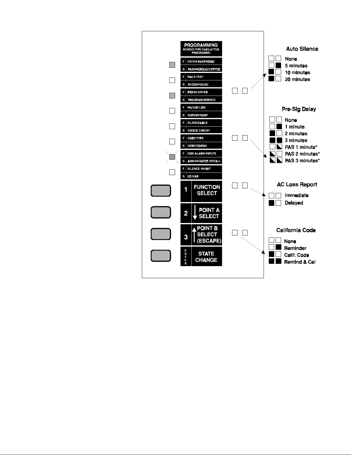
To program the features of AUTO SILENCE, PRESIGNAL DELAY, and
CALIFORNIA CODE, key in the password 123-3211 and push ENTER.
In addition to PASSWORD ACCEPTED
and PROGRAM/SERVICE LEDs, the
NON-ALARM LED will flash on the
CPU.
Press the ENTER switch to scroll through
the options for AUTO SILENCE until the
LEDs reflect the desired choice.
Press the FUNCTION SELECT switch
to store the option setting in memory and
advance to the next point to be programmed. Again, press the ENTER
switch until the LEDs reflect the desired
choice, followed by the FUNCTION SE-
LECT switch to store the data.
To exit extended programming at any
time, remove the programming key. The
123-3211 password does not allow access
to any other program features and does
not cause the system to reconfigure.
CPU-2000
*Applies only to zones selected as "Verified/PAS."
S2000 15017 Rev H 10/08/96 P/N 15017:H
57
Page 58

SECTION EIGHT: OPERATION
CPU LED Indicators
A green LED that indicates the presence of normal AC power. This LED is turned off
when the AC line voltage falls below normal.
A red LED that indicates an alarm condition. This LED initially flashes during alarm
(the CPU will also sound a continuous audible tone). Silencing or acknowledging the
alarm(s) turns the audible tone off and causes the LED to illuminate steadily. Subsequent
alarms will resound the audible tone and flash their LEDs. Alarm signals latch until the
control panel is reset.
A yellow LED that indicates activation of a circuit programmed to monitor supervisory
devices.
Indicates the presence of a trouble condition in the system.
Indicates the failure of a module in the control unit or an annunciator failure.
Indicates 1) that a power supply is not functioning correctly, 2) AC line voltage is below
normal, 3) improper battery voltage, or 4) that a ground fault exists. Additional information is displayed on internal LEDs located on power supply assemblies.
Indicates that an output circuit is silenced. Indication will remain until the reset switch is
depressed.
Indicates that a circuit(s) within the system has been manually disabled.
CPU Control Switches
Depressing ACKNOWLEDGE turns the audible tone off and switches LED operation
from flashing to steady. A subsequent trouble or alarm will resound the audible tone and
flash appropriate LEDs.
Returns all silenceable outputs, which were automatically activated by the alarm condition, to their non-alarm state. A subsequent alarm can reactivate alarm outputs.
The System Reset Switch will reset the system provided that the alarm condition is clear.
Holding this switch depressed will sequentially light (lamp test) all LEDs.
The Lamp Test Switch illuminates all the LEDs in the system for as long as the switch is
held down. This switch can also be used to disable or enable individual circuits.
Note: The CPU produces a pulsed tone for troubles, disabled outputs,
and supervisory conditions. A continuous tone is generated for alarms.
58
S2000 15017 Rev H 10/08/96 P/N 15017:H
Page 59

8.1 CPU-2000 CIRCUITS
The CPU Module contains: 1) Two supervised notification appliance circuits that can be used to control evacuation signaling
devices such as bells, chimes, horns, and strobes. 2) An alarm relay that can control external devices such as elevators, and
doors. 3) A Remote Signaling/Municipal Tie output for connection to a municipal fire department, central station, or a
remote monitoring station.
Notification Appliance Circuit #1
Green LEDs:
Each output has a green LED that
indicates activation of that circuit.
Notification Appliance Circuit #2
Municipal Box/Remote Signaling Tie
Form-C Alarm Relay
Yellow LEDs:
Each output circuit has a yellow LED that indi-
cates trouble conditions or disabled outputs. New
troubles are indicated by a flashing LED.
S2000 15017 Rev H 10/08/96 P/N 15017:H
59
Page 60
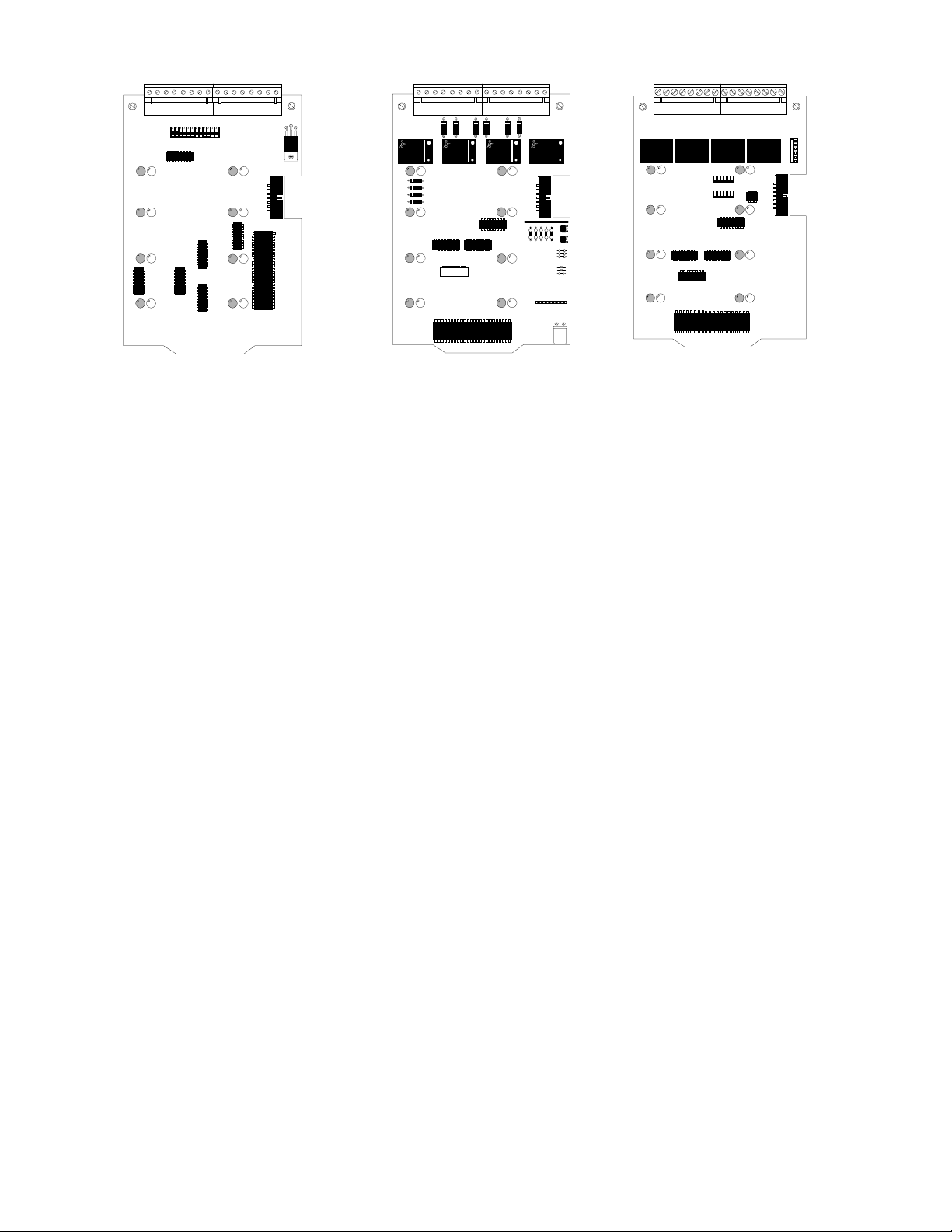
IZ Series
Initiating Zone Module
Each Initiating Zone Module will monitor up to eight initiating zones (groups)
of initiating devices (smoke detectors,
pull stations, heat detectors) for alarm
signals. It also checks the integrity of the
building wiring between the module and
the initiating devices. The IZ-4F and IZ8F modules convey the status of the initiating zones and their wiring to the CPU
module and at the direction of the CPU
will light the appropriate LEDs to display alarm and trouble conditions (broken wire, inactive circuit, etc.).
The red LEDs indicate alarm conditions.
New alarms are indicated by a flashing
LED and a steady audible tone. Silencing an alarm turns the audible tone off
and causes the LED to illuminate steadily.
The yellow LEDs indicate an initiating
zone trouble or a disabled zone. New
troubles are indicated by a flashing LED
and a pulsed audible tone. Silencing a
trouble turns the audible tone off and
switches LED operation from flashing
to steady. A subsequent trouble from a
different initiating zone will resound the
audible tone and flash its LED. Trouble
signals will self-restore as soon as the
trouble conditions are corrected.
IC-4F
Notification Circuit Module
Each Indicating Circuit Module will
control and monitor up to eight notification appliance circuits (with an ICE4F expander installed) of evacuation
signaling devices, such as bells, chimes,
horns, and lights. The IC-4F module
conveys the status of the notification
appliance circuits and their wiring to the
CPU module and at the direction of the
CPU will light the appropriate LEDs to
display activation and trouble conditions (broken wire, inactive circuit). The
notification appliance circuits activate
automatically during an alarm condition
according to a program instructions
stored in CPU nonvolatile memory.
The green LEDs indicate an activated
notification appliance output.
The yellow LEDs indicate a notification circuit trouble or a disabled circuit.
New troubles are indicated by a flashing LED and a pulsed audible tone. Silencing a trouble turns the audible tone
off and causes the LED to illuminate
steadily. A subsequent trouble from a
different circuit will resound the audible
tone and flash the associated trouble
LED. Trouble signals will self-restore
as soon as the trouble condition has
been corrected.
CR-4F
Control Relay Modules
Each Control Relay Module controls
up to eight relays (with a CRE-4F expander installed) which can be connected to control external devices including elevators, doors, and air handling equipment. These relays will be
activated automatically during an
alarm condition according to program
instructions stored in CPU module's
memory.
The green LEDs indicate that the associated control relay has been activated.
The yellow LEDs indicate that the associated control relay output has been
disabled.
60
This module is programmable for California Code. Cutting D35 programs this
card for California Code.
S2000 15017 Rev H 10/08/96 P/N 15017:H
Page 61
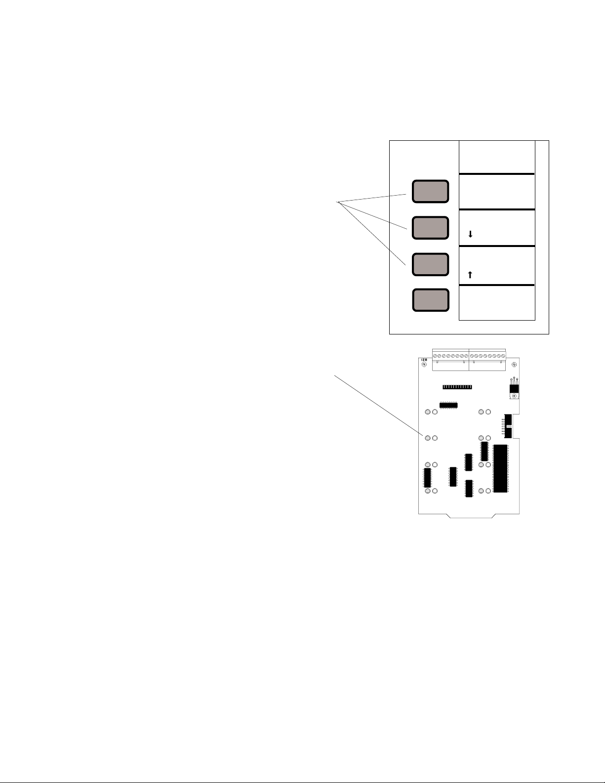
8.2 DISABLING/ENABLING CIRCUITS
Note: The disable feature will not work if the CPU Write Inhibit Switch has been set (refer to page 51 for details).
For servicing of the Sensiscan 2000, input or output circuits can be disabled. To disable a circuit, a 1-2-3 key sequence must
be entered and the operator must advance to the circuit to be disabled. **This does not work in program mode.
1) Press the LAMP TEST switch and hold it in throughout
the remainder of this procedure.
2) Press 1, 2, 3. If any circuits have been previously
disabled, they will be indicated by illumination of their
left-hand LED (red for initiating circuits, green for all
others).
The position of the circuit pointer is indicated by the
flashing yellow LED.
To move forward in the circuit map, press Switch 3
(SYSTEM RESET). To move backward in the
circuit map, press Switch 2 (SIGNAL SILENCE).
3) Move forward or reverse until the pointer stops at the
circuit to be disabled.
4) Press Switch 1 (ACKNOWLEDGE) to turn on the lefthand LED on the circuit to be disabled. When this
LED is on, the circuit has been disabled.
A circuit can be re-enabled by pressing Switch 1 until
the left-hand LED goes out.
5) Repeat steps 3 and 4 until all disabling/enabling has
been accomplished.
6) Release the LAMP TEST switch to exit Disable/Enable
mode. The control panel will return to operation with
the selected circuits disabled.
ACKNOWLEDGE
SILENCE TONE
1
SIGNAL
2
SILENCE
SYSTEM
RESET
3
LAMP TEST
DISABLE/ENABLE
Caution: Disabling a circuit will reduce or eliminate fire protection.
S2000 15017 Rev H 10/08/96 P/N 15017:H
61
Page 62

SECTION NINE: SENSISCAN 2000 TESTING
9.1 ACCEPTANCE TEST
Upon completion of the original installation and following subsequent modifications, a complete operational test should be
conducted on the entire installation for the purpose of verification of compliance with the applicable NFPA standards.
Testing should be conducted by a factory-trained distributor in the presence of a representative of the Authority Having
Jurisdiction and the Owner's Representative. Follow procedures contained in NFPA Standard 72-1993, Chapter 7, "Inspection, Testing and Maintenance."
9.2 PERIODIC TESTING AND SERVICE
Periodic testing and servicing of the Sensiscan 2000, all initiating devices and notification appliances, and any other associated equipment is essential to insure proper and reliable operation. Testing and servicing should be in accordance with the
schedules and procedures outlined in: 1) NFPA 72-1993, Chapter 7, "Inspection, Testing and Maintenance" and 2) the
service manuals and instructions for the peripheral devices contained in your system. Correct any trouble condition or
malfunction immediately.
9.3 OPERA TIONAL CHECKS
Between formal periodic testing and servicing intervals, the following operation checks should be performed monthly or
more frequently when required by the Authority Having Jurisdiction.
1) Check that the green "AC POWER" LED is illuminated.
2) Check that all yellow LEDs are off.
3) Holding "SYSTEM RESET" depressed should sequentially light all system LEDs.
4) Before proceeding, a) notify fire department and/or central alarm receiving station if alarm conditions are transmitted; b) notify facility personnel of test so that alarm sounding devices are ignored during test period. When
necessary, activation of alarm notification appliances can be prevented by disabling those circuits.
5) Activate an initiating device circuit via an alarm initiating device and check that all active notification appliances
function. Reset the alarm initiating device, the control panel, and any other associated equipment.
6) Repeat Step 5 for each initiating device circuit.
7) Remove AC power, activate an initiating device circuit via an alarm initiating device and check that active notification appliances sound, and alarm indicators illuminate. Measure the battery voltage while notification appliances
are activated. Replace any battery with a terminal voltage less than 21.6 volts. Replacement batteries may be
obtained from FireLite. Minimal replacement battery capacity is indicated on the control panel marking label.
Reapply AC Power. Note: This test requires fully charged batteries, if batteries are new or discharged due to a
recent power outage, allow the control panel to charge batteries for 48 hours before testing.
8) Check that all yellow LEDs are off and that the green "AC POWER" LED is illuminated.
9) Notify fire, central station and/or building personnel that test is complete.
62
S2000 15017 Rev H 10/08/96 P/N 15017:H
Page 63

9.4 BATTERY CHECKS AND MAINTENANCE
Maintenance-free sealed lead-acid batteries used in Sensiscan 2000 do not require the addition of water or electrolyte. They
are charged and are maintained in a fully charged state by the main power supply's float charger during normal system
operation. A discharged battery will charge at 1.5 amps (typically) and obtain its float voltage of 27.6 volts within 48 hours.
Replace any battery that is leaking or damaged. Replacement batteries may be obtained from Fire-Lite. Minimal replacement battery capacity is indicated on the control panel marking label. To check battery and system, Refer to Section "Operational Checks" above.
CAUTION!
Batteries contain Sulfuric Acid which can cause severe burns to the skin and eyes and
damage to fabrics. In the event a battery leaks and contact is made with the Sulfuric Acid,
immediately flush skin and/or eyes with water for at least 15 minutes. For eyes, seek imme-
diate medical attention. A good neutralizing solution for Sulfuric Acid is water and house-
hold baking soda. Care should be taken to insure proper handling of the battery to prevent
short-circuiting. Accidental shorting of the leads from uninsulated work benches, tools,
bracelets, rings, and coins should be avoided. Shorting the battery leads can damage the
battery, equipment, and could cause injury to personnel.
9.5 WALK TESTING THE SENSISCAN 2000
In order to execute Walk Test from the Sensiscan 2000, the CPU Programming Key must be inserted.
Enter the Walk Test password (123-1233) then press ENTER. Depress the Enter Switch again. The PASSWORD ACCEPTED LED will light and the WALK TEST LED will flash. Activate an initiating device and all output circuits that are
programmed as silenceable will activate for approximately four seconds. If an initiating device circuit is activated more
than once, the outputs will activate for approximately one second. Once an initiating circuit has been activated, its red LED
will flash. All of the red LEDs on the initiating circuit modules will illuminate. The green LEDs on all notification appliance
circuits that are silenceable will illuminate.
Testing Initiating Circuits for Trouble
Inducing a trouble into an initiating circuit will activate all output circuits that are programmed as silenceable. The outputs
will remain activated until the trouble is cleared. After a circuit is tested for trouble, the yellow LED for that circuit will
flash.
Testing Notification Appliance Circuits for Trouble
Inducing a trouble into a notification circuit will activate the particular circuit and pulse the circuit at one second on/off rate
until the trouble is cleared.
Exiting Walk Test
To exit Walk Test, remove the programming key.
NOTE: Four-wire smoke detectors cannot be tested under Walk Test.
S2000 15017 Rev H 10/08/96 P/N 15017:H
63
Page 64

APPENDIX A: SUPPLY CALCULA TIONS
A.1 THE FIRE ALARM CIRCUIT
The control panel requires connection to a separate dedicated AC fire alarm circuit, which must be labeled "FIRE ALARM."
This circuit must connect to the line side of the main power feed of the protected premises. No other equipment may be
powered from the fire alarm circuit. The AC circuit wire run must run continuously, without any disconnect devices, from
the power source to the fire alarm control panel. Overcurrent protection for this circuit must comply with Article 760 of the
National Electrical Code as well as local codes. Use #12 AWG wire with 600V insulation for this circuit.
eciveDseciveDfo#
EFA42-SPM/FA42-SPM
ro
EFB42-SPM/FB42-SPM
EF42-SPVA/F42-SPVA][X5.0/0.1
etomeRE42-54R/42-54R
regrahC
ylpitluM
yB
1X9.0/8.19.0/8.1
1X5.0/0.1
=*daoLmralAeriFyradnoceSrofnmuloCmuS spma
tnerruC
ni
spmA
tnerruClatoT
Table A-1: AC Fire Alarm Circuit
Note
Devices rated for 220/240 VAC operation ("E" products) will draw one half
of the current of devices rated for 120 VAC operation.
Use Table A-1 to determine the total amount of current, in AC amps, that the AC service must be capable of supplying to the
system.
A.2 THE MAIN POWER SUPPLY
The main power supply must be capable of powering all internal system devices (and several external types of devices)
continuously during non-fire alarm conditions. Use Table A-2A to determine the Non-Fire Alarm Load on the main power
supply regulator when a primary power is applied. A finite amount of additional current must be provided by the power
supply during a fire alarm condition. Use Table A-2B to determine the additional current needed during fire alarms. The
requirements for non-fire alarm and fire alarm current loads cannot exceed the capabilities of the power supply in either
case.
The MPS-24AF provides up to 3.0 amps of regulated current for operating the system in standby (non-fire alarm) and up to
6.0 amps during fire alarms. The MPS-24AF contains battery charging circuitry and a 1-amp regulated output for powering
four-wire smoke detectors. The MPS-24BF provides 750 mA of regulated power for system modules and 2.0 amps for
Notification Appliances.
64
S2000 15017 Rev H 10/08/96 P/N 15017:H
Page 65

SENSISCAN 2000 SYSTEM CURRENT DRAW CALCULATION TABLE (TABLE A-2A)
Note: The Primary Power Source Non-Alarm Current and Alarm Current columns of this table are not battery calculations.
They are simply current calculations to confirm that the main power supply can supply enough current to support the system
during Primary Non-Alarm and Fire Alarm conditions.
Note: Throughout these current calculation tables, the word "primary" refers to the FACP's primary source of power, i.e.
AC power. The word "secondary" refers to the FACP's backup batteries (or any other 24 VDC uninterruptable, regulated
power supply listed for Fire Protective Signaling and connected in place of the batteries).
Part One - Non-Alarm Current (Primary Power Source): This column of Table A-2A allows the user to calculate the
current that will be drawn from the main power supply during a non-alarm condition, with AC power applied. This current
draw cannot exceed 750 mA on the MPS-24BF or 3.0 amps on the MPS-24AF. This column does not account for current
drawn from TB2-3 and TB2-4 in non-alarm conditions on the MPS-24BF which is limited to 0.800 amps, exclusive of the
0.750 amps limit on the non-alarm current load. Current drawn from TB2-1 and TB2-2 cannot exceed 0.200 amps at any
time on the MPS-24BF.
Part Two - Fire Alarm Current (Primary AC Power): The second column of Table A-2A allows the system designer to
determine the additional current load that must be supported by the main power supply during a fire alarm condition with
primary power applied. This current drawn during a fire alarm cannot exceed 0.750 amps on the MPS-24BF. This column
does not account for current draw from TB2-3 and TB2-4 in fire alarm which is limited to 2.0 amps exclusive of the 0.750
amps fire alarm load. The fire alarm load cannot exceed 6 amps for the MPS-24AF and 2.3 amps for the MPS-24BF.
Note: Typically, a system should be designed around the capacity to activate all output circuits and relays, and
support fire alarms on no less than 10% of initiating device circuits (subject to the requirements of the Local
Authority Having Jurisdiction (LAHJ).
Concerning four-wire detectors: In Table A-2A, the current to be entered for four-wire smoke detectors is the
manufacturer's rated fire alarm current minus the manufacturer's rated non-fire alarm current.
Concerning notification appliances: The main power supply provides a regulated supply for notification appliance
circuits, permitting the use of any 24 VDC notification appliances UL listed for Fire Alarm Systems. Enter into
Table A-2A the respective current draws of notification appliances and other external devices to be powered by the
main power supply during a fire alarm.
Part Three - Non-Fire Alarm Current (Secondary battery power): The last column of Table A-2A allows the system
designer to calculate the secondary non-fire alarm current. This is the current that will be drawn from the main power supply
in a non-fire alarm condition during AC power loss. This figure is required to complete the standby battery calculations.
After adding up all the individual current draws, the total figure is then transferred to Table A-2C.
S2000 15017 Rev H 10/08/96 P/N 15017:H
65
Page 66

ecruoSrewoPyramirP ecruoSrewoPyradnoceS
yrogetaC
ytQ=]wardtnerruc[XlatotytQ
UPC1=]130.0[x130.01 =]322.0[x322.01 =]130.0[x130.0
EFA42-SPM/FA42-SPM
EFB42-SPM/FB42-SPM
EF42-SPVA/F42-SPVA][=]900.0[x][=]900.0[x][=]900.0[x
F8-ZI
FA-EZI
F4-RC,F4-CI
F4-ECI
F4-ERC
4-CT,2-CT
FA23-MFA,FTA61-MFA
FA23-MCA,FTA61-MCA
FA61-MFA
)09351.coD
ytilibitapmoCeciveDehtot
senoz03ot1
senoz04ot13
senoz94ot14
senoz65ot05
1
][
][
][
][
][
][
][
][
otrefer(XA23-MFA,XTA61-MFA
][
][
refer(srotceteDekomSeriW-2
][
)swardtnerrucroftnemucoD
][
][
)spma(tnerruCmralA-noN)spma(tnerruCmralA)spma(tnerruCmralA-noN
tnerruc[X
=]ward
=]460.0[x
=]260.0[x
=]740.0[x
=]400.0[x
=]700.0[x
=]100.0[x
elbacilppaton
=]700.0[x
=]040.0[x
=]040.0[x
=]520.0[x
=][x
=][x
=][x
=][x
=][x
ELBACILPPATON
1
][
][
][
][
][
][
][
][
][
][
][
][
][
][
][
][
][
][
=]460.0[x
=]260.0[x
=]740.0[x
=]300.0[x
=]270.0[x
=]560.0[x
=]560.0[x
=]270.0[x
=]650.0[x
=]650.0[x
=]560.0[x
=][x
=][x
=][x
=][x
=][x
=]021.0[x
=]061.0[x
=]002.0[x
=]042.0[x
latotytQ=]wardtnerruc[Xlatot
1
][
][
][
][
][
][
][
][
][
][
][
][
][
=]401.0[x
=]220.0[x
=]740.0[x
=]400.0[x
=]700.0[x
=]100.0[x
elbacilppaton
=]700.0[x
=]040.0[x
=]040.0[x
=]520.0[x
=][x
=][x
=][x
=][x
=][x
ELBACILPPATON
rotacinummoCA119
rotacinummoCTCADU
rewopgniwardsecivedrehtO
rewoPecnailppAnoitacifitoN
)3dna1setonees(
syaleRnoisivrepuSrewoP
)1etonees(
morfwarDeciveDgnisaeleR
stiucricF4-CT/F2-CT
)2dna1setonees(
stiucriCnoitatSetomeR
)1etonees(
srotceteDekomSeriW-4
)1etonees(
slatotrofnmulochcaemuS:latotmralaerif-non,yramirP:latotmrala,yramirP
][
][
][
gnidulcxeylppusrewopehtmorf
][
][
][
][
][
][=]810.0[x][=]810.0[x][=]810.0[x
][
][
=]030.0[x
=]040.0[x
=][x
=][x
=][x
=][x
=][x
=][x
ELBACILPPATON][=][x ELBACILPPATON
=][x
=][x
][
][
][
][
][
][
][
][
][
][
=]761.0[x
=]001.0[x
=][x
=][x
=][x
=][x
=][x
=][x
=][x
=][x
][
][
][
][
][
][
][
][
][
][
=]030.0[x
=]040.0[x
=][x
=][x
=][x
=][x
=][x
=][x
=][x
=][x
mralaerif-non,yradnoceS
:latot
Table A-2A: Sensiscan 2000 System Current Draw Calculations
Notes:
1) The total regulated load current supplied to external circuits cannot exceed 3.0 amps (MPS-24AF) or 0.200 amps (MPS-24BF).
2) MPS-24BF: Enter only notification appliance draw from TC-2F/TC-4F circuits. MPS-24AF: Enter total notification appliance draw for
entire system. Do not include power from AVPS-24F supplies!
3) The Alarm Load cannot exceed 6 amps for the MPS-24AF. For the MPS-24BF, the alarm load limit is 750 mA for both internal needs and
power drawn from TB2-1 and TB2-2. The alarm load limit is 2.0 amps from TB2-3 and TB2-4.
66
S2000 15017 Rev H 10/08/96 P/N 15017:H
Page 67

Maximum Secondary Power Fire Alarm Current Draw
Use Table A-2B to determine the maximum current requirements of secondary power source during fire alarm conditions.
The total obtained in Table A-2B is the amount of current that the batteries must be capable of supplying. This figure will
be used in Table A-2C to determine the size of the batteries needed to support five minutes of fire alarm operation.
Table A-2B assumes that while in a fire alarm condition, the batteries must feed the main power supply and any additional
supplies (AVPS-24F/AVPS-24FE) with the maximum rated power each supply can provide. Note: Due to the maximum
rating of 9 amps imposed when using PS-12250 batteries, it may be necessary to calculate the exact requirements of the
secondary supply. In that case, add the Secondary Non-Fire Alarm Load obtained in Table A-2A to the total fire alarm
current draw of all Notification Appliances in the system and substitute that figure in Table A-2B for the main power supply
and any additional supplies.
eciveD
epyT
rewoP
:seilppuS
ro
rebmuNledoM
EFA42-SPM/FA42-SPM
EFB42-SPM/FB42-SPM
EF42-SPVA/F42-SPVA
fo#
seciveD
1X
[
]
X0.3=
tnerruC
)spma(
0.6
ro
=
39.2
daoLmralAyradnoceSrofnmuloCmuS =spma
latoT
tnerruC
Table A-2B: Maximum Secondary Power Fire Alarm Current Draw
eriF-noNyradnoceS
drihtmorf(daoLmralA
)A2-AelbaT,nmuloc
X
mralAeriFyradnoceS
daoL
)B2-AelbaTmorf(
X
-noNyradnoceSderiuqeR
emiTybdnatSmralAeriF
)sruoh06ro42(
=
sruoH
emiTmralAeriFderiuqeR
,480.0retne,setunim5roF(
)52.0retne,setunim51rof
=
sruoHerepmAyradnoceSlatoTrofnmuloCmuS
=detaluclac
mralAeriF-noN
yradnoceS
pmAybdnatS
eriFyradnoceS
ruoHpmAmralA
tnemeriuqeR
=2.1XrotcafgnitaredehtybylpitluM
deriuqeRsruoHerepmAyradnoceSlatoT spma
Table A-2C: Secondary Power Standby and Fire Alarm Load
Notes:
1. NFPA 72-1993 Local, Central Station, and Proprietary Fire Alarm Systems require 24 hours of standby power followed by five
minutes in alarm. NFPA 72-1993 Auxiliary and Remote Station Fire Alarm Systems require 60 hours of standby power followed by
five minutes in alarm. Batteries installed in a system powered by a generator need to provide at least four hours of standby power.
2. If the total exceeds 55AH (17AH on the MPS-24BF), a UL-listed Uninterruptable Power Supply (UPS) with sufficient capacity is
needed. If the system does not have battery backup, a UPS must be installed in the same room as the FACP.
S2000 15017 Rev H 10/08/96 P/N 15017:H
67
Page 68

Calculating battery size needed
Table 8.2E sums the standby and alarm loads to
arrive at the battery size, in ampere hours, needed
to support the system. Each main power supply
has a specific range of batteries that can be
charged properly. Select batteries that meet or
exceed the Total Ampere-Hours calculated and
the are within the acceptable charger range:
Battery Charger Amp-Hour Range:
MPS-24AF (9-55AH)
MPS-24BF (6.5-17AH)
yrettaB
eziS
HA0.7
HA5.9
HA21
HA71
HA52
HA55
egatloV
gnitaR
stlov21
stlov6
stlov21
stlov21
stlov21
stlov21
rebmuN
deriuqeR
owt
ruof
owt
owt
owt
owt
traP
rebmuN
0721-SP
596-SP
02121-SP
07121-SP
05221-SP
00621-SP
eziStenibaC
F3B-BAC,F3A-BAC
F3B-BAC,F3A-BAC
F3B-BAC,F3A-BAC
F3B-BAC,F3A-BAC
F3B-BAC,F3A-BAC
F3B-BAC,F3A-BAC
68
S2000 15017 Rev H 10/08/96 P/N 15017:H
Page 69

Sensiscan 2000 Programming Log
stiucriCnoitacifitoNdeppaM
eludoM
noitisoP
tiucriC
rebmuN
enoZ
lebaLtiucriCgnitaitinI
epyT
mralA
yfireV
1DNI2DNIxoB.M
stiucriC0002-UPC
mralA
)#tiucriC&
noitsisoPeludoMtuptuOretnE(
yaleR
S2000 15017 Rev H 10/08/96 P/N 15017:H
epyTenoZ
retteLenOretnE
F eriF- R yaleR-
W wolfretaW- CT lortnoCemiT-
S yrosivrepuS- VA lausiVoiduA-
N mralAnoN-
dnegeL
epyTnoitacifitoN
)s(retteLretnE
MSR etomeR-
lapicinuM/noitatS
-T eiT
69
Page 70

eludoM
noitisoP
tiucriC
rebmuN
lebaL
tiucriCnoitacifitoN
A11
A11
A11 TM/SR
A11
tiucriC
epyT
?dedoC?elbaecneliS
CAB-A3F
0002-UPC
A1B1C1D1
CAB-B3F
0002-UPC
A1B1C1D1
A2B2C2D2
:epyTedoC
:tibihnIecneliS
:ecneliSmralA
yaleDlangiS-erP
70
q laropmeT q emiThcraM
q enoN q .ces03 q .nim1 q .nim5
q enoN q .nim5 q .nim01 q nim02
q enoN q .nim1 q .nim2 q .nim3
Cabinet Module Position La y out
1. Cross out unused rows.
2. Fill module blocks with appropriate model number (IZ-8F, IZE-AF, IZ-4F, IC-4F, ICE-4F, CR-4F,
CRE-4F, TC-2F, TC-4F)
sgnitteSediW-metsyS
S2000 15017 Rev H 10/08/96 P/N 15017:H
epyTenoZ
enOretnE
retteL
F eriF- R yaleR-
W wolfretaW- CT lortnoCemiT-
S yrosivrepuS- VA lausiVoiduA-
N mralAnoN-
dnegeL
epyTnoitacifitoN
)s(retteLretnE
MSR etomeR-
lapicinuM/noitatS
-T eiT
Page 71

Notes
S2000 15017 Rev H 10/08/96 P/N 15017:H
71
Page 72

Limited Warranty
Fire-Lite® warrants its products to be free from defects in materials and workmanship
for eighteen (18) months from the date of manufacture, under normal use and service.
Products are date stamped at time of manufacture. The sole and e xclusive ob ligation
of Fire-Lite® is to repair or replace, at its option, free of charge for parts and labor, any
part which is defective in materials or workmanship under normal use and service.
For products not under Fire-Lite® manufacturing date-stamp control, the warranty is
eighteen (18) months from date of original purchase by Fire-Lite®'s distributor unless
the installation instructions or catalog sets forth a shorter period, in which case the
shorter period shall apply. This warr anty is void if the product is altered, repaired or
serviced by anyone other than Fire-Lite® or its authorized distributors or if there is a
failure to maintain the products and systems in which they operate in a proper and
workable manner . In case of defect, secure a Return Material Authorization f orm from
our customer service depar tment. Return product, transportation prepaid, to Fire-
Lite®, One Fire-Lite Place, Northford, Connecticut 06472-1653.
This writing constitutes the only warranty made by Fire-Lite® with respect to its products.
Fire-Lite® does not represent that its products will prevent any loss by fire or otherwise,
or that its products will in all cases provide the protection for which they are installed
or intended. Buyer acknowledges that Fire-Lite® is not an insurer and assumes no
risk for loss or damages or the cost of any inconvenience, transportation, damage,
misuse, abuse, accident or similar incident.
Fire-Lite® GIVES NO WARRANTY, EXPRESSED OR IMPLIED, OF
MERCHANT ABILITY, FITNESS FOR ANY P AR TICULAR PURPOSE, OR OTHERWISE
WHICH EXTEND BEY OND THE DESCRIPTION ON THE FACE HEREOF. UNDER
NO CIRCUMSTANCES SHALL Fire-Lite® BE LIABLE FOR ANY LOSS OF OR
DAMA GE T O PROPER TY, DIRECT , INCIDENTAL OR CONSEQUENTIAL, ARISING
OUT OF THE USE OF, OR INABILITY TO USE Fire-Lite® PRODUCTS.
FURTHERMORE, Fire-Lite® SHALL NOT BE LIABLE FOR ANY PERSONAL INJUR Y
OR DEATH WHICH MAY ARISE IN THE COURSE OF, OR AS A RESULT OF,
PERSONAL, COMMERCIAL OR INDUSTRIAL USE OF ITS PRODUCTS.
This warranty replaces all previous warranties and is the only warranty made by Fire-
Lite®. No increase or alteration, written or verbal, of the obligation of this warranty is
authorized.
"Fire-Lite" is a registered trademark.
One Fire-Lite Place, Northford, CT 06472
Phone: (203) 484-7161
FAX: (203) 484-7118
Technical Publishing Document WARFBG-D.P65 11/04/98
Page 73

Sensiscan 2000 Operating Instructions
NORMAL STANDBY OPERATION: 1) The green AC POWER indicator must be lit, 2) all alarm (red LEDs) and trouble
indicators (yellow LEDs) should be off.
ALARM CONDITION: Activation of a compatible detector or any normally open fire alarm initiating device will result in the
following action by the System 500 control panel: 1) activate alarm notification, control, and signaling outputs as programmed,
2) light the Red SYSTEM ALARM LED and the associated initiating circuit alarm LED(s), and 3) A steady audible tone will sound
until the alarm is acknowledged or silenced. The controlled outputs will remain activated and the associated alarm LEDs will
flash until the alarm has been silenced or acknowledged, or the system has been reset.
If PRESIGNAL DELAY has been pro-
grammed, the activation of all
silenceable
layed by the time marked at right. For
Positive Alarm Sequence (PAS): If the
ACKNOWLEDGE or SILENCE keys
are not pressed within 15 seconds of
initiation of a first (and only) alarm,
output signals will be activated. Otherwise, the programmed PAS 1, 2, or
three-minute time delay will take effect.
ACKNOWLEDGE (SILENCE TONE): Depressing the ACKNOWLEDGE switch will turn the audible tone off and switch
operation of associated LED(s) from flashing to steady. New alarms and/or troubles will resound the audible tone and flash
their associated LED(s).
ALARM SILENCING PROCEDURE: Alarm notification
appliance circuits, control relays and signalling circuits that
have been programmed as silenceable may be silenced by
depressing the SIGNAL SILENCE switch on the CPU control
panel (top left module). Subsequent alarms will reactivate
alarm outputs.
SIGNAL SILENCE should not pressed until it is
determined that an evacuation of the building is not required!
output circuits will be de-
None selected
❑❑
❑
❑❑
1 Minute
❑❑
❑
❑❑
2 Minutes
❑❑
❑
❑❑
3 Minutes
❑❑
❑
❑❑
PAS 1 Minute
❑❑
❑
❑❑
PAS 2 Minutes
❑❑
❑
❑❑
PAS 3 Minutes
❑❑
❑
❑❑
If ALARM SILENCE has been programmed, all
silenceable output circuits will be shut off after
the time marked at right.
None selected
❑❑
❑
❑❑
5 Minutes
❑❑
❑
❑❑
10 Minutes
❑❑
❑
❑❑
20 Minutes
❑❑
❑
❑❑
❑❑
❑
If SIGNAL SILENCE INHIBIT has
been programmed, Signal Silence will not function for the inhibit time marked at right.
❑❑
❑❑
❑
❑❑
❑❑
❑
❑❑
❑❑
❑
❑❑
None selected
30 Seconds
1 Minute
5 Minutes
ALARM RESET: After locating and correcting the alarm condition, reset the control panel by depressing the SYSTEM
RESET switch on the CPU control panel (top left module).
DISABLE/ENABLE: Refer to the System 2000 Installation Manual. WARNING: Disabling a circuit will reduce
or eliminate fire protection.
TROUBLE CONDITION: Activation of a trouble signal
under normal operation indicates a condition that requires immediate correction. Carefully note which indicators (LEDs) are illuminated and contact your local
service representative. The audible tone may be silenced by depressing the ACKNOWLEDGE switch,
subsequent trouble(s) will reactivate the audible tone.
Trouble LEDs will continue to display the trouble
condition(s) until the trouble(s) is corrected.
Sensiscan 2000 Programmer: Mark the check-boxes above as appropriate. This sheet must be framed and mounted adjacent to
control panel. For more information, refer to the Sensiscan 2000 Installation Manual
Local Service Representative
Name:
Company:
Address:
Telephone:
Page 74

CPU LABELS
Programming Operating (left) Operating (right)
PROGRAMMING
REMOVE THIS CARD
AFTER PROGRAMMING
F
ENTER PASSWORD
S
PASSW ORD ACCEPTED
F
WALK TEST
RECONFIGURE
S
PRESS ENTER
F
S
PROGRAM / SERVICE
WATERFLOW
F
SUPERVISORY
S
SILENCEABLE
F
CODED CIRCUIT
S
CODE TYPE
F
VERIFIED / PAS
S
NON ALARM INPUTS
F
ANNUNCIATOR INSTALL
S
SILENCE INHIBIT
F
I / O MAP
S
FUNCTION
1
SELECT
POINT A
2
SELECT
Sensiscan
2000
AC
POWER
SYSTEM
ALARM
SUPERVISORY
SIGNAL
SYSTEM
TROUBLE
ANNUNCIATOR OR
MODULE TROUBLE
AC/BATT/GND
F AULT
SIGNAL
SILENCE
DISABLED
CIRCUITS
ACKNO WLEDGE
SILENCE TONE
1
SIGNAL
SILENCE
2
INDICATING
CIRCUIT 1
INDICATING
CIRCUIT 2
REMOTE
SIGNALING
MUNICIPAL
TIE
S
lide-In Labels for the Fire•Lite
Sensiscan 2000 Fire Alarm Control Panel
These pages contain slide-in labels for the Sensiscan 2000. Remo v e these
pages and carefully cut out the labels for insertion in the CPU-2000 modules
and the VP-1F dress panel. The labels slip into the back side of the CPU's
faceplated and the back-side of the VP-1F.
Dress Plate Labels: Slide-in labels provide inf ormation directly ov er the
modules of the Sensiscan 2000. These module labels contain pre-printed
"zone" designators for up to 56 circuits. Up to four lines of custom information
can be typed into each zone window when the labels are cut on the upper line.
If up to five lines of custom information need to be typed, cut the labels on the
bottom line.
Note: To ensure the best fit, cut directly along
the dotted line surrounding each label.
3
E
N
T
E
R
POINT B
SELECT
ST ATE
CHANGE
SYSTEM
RESET
LAMP TEST
DISABLE / ENABLE
3
RELAY
ALARM
 Loading...