


第
页
FIBOCOM H330S Hardware
User Manual
Version:V1.2.2
Date:2018-12-22
1 页 共 49

Applicability Type
No. Type Note
1 H330S-Q50-00
2 H330S-Q30-00 NA
3 H330S-A30-00 NA
4 H330S-A50-00 NA
5 H330S-A30-20 NA
6 H330S-A50-20
7 H330S-Q50-20
8 H330S-Q30-20
9 H330S-Q30-10 NA
10 H330-A30-80 NA
11 H330S-A30-90 NA
12 H330S-Q30-90 NA
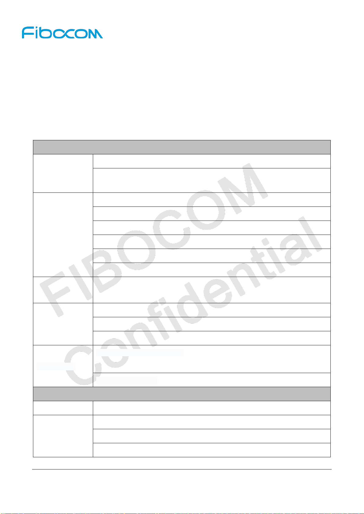
The difference of H330S series wireless module as listed below:
GSM/GPRS/EDGE
Type
Band(MHz)
H330S-Q50-00 850/900/1800/1900 850/900/1900/2100
Only MiniPCIe
Only MiniPCIe
NA
WCDMA
Band(MHz)
Analog Digital
Audio
HSDPA
(Mbps)
21 5.76
HSUPA
(Mbps)
H330S-Q30-00 850/900/1800/1900 850/900/1900/2100 7.2 5.76
H330S-Q30-90 850/900/1800/1900 850/900/1900/2100 7.2 5.76
H330S-A30-00 900/1800 900/2100 7.2 5.76
H330S-A50-00 900/1800 900/2100 21 5.76
H330-A30-80 900/1800 900/2100 7.2 5.76
H330S-A30-90 900/1800 900/2100 7.2 5.76
H330S-A30-20 900/1800 900/2100
H330S-A50-20 900/1800 900/2100 21 5.76
H330S-Q50-20 850/900/1800/1900 850/900/1900/2100 21 5.76
H330S-Q30-20 850/900/1800/1900 850/900/1900/2100 7.2 5.76
Reproduction forbidden without Fibocom Wireless Inc. written authorization - All Rights Reserved.
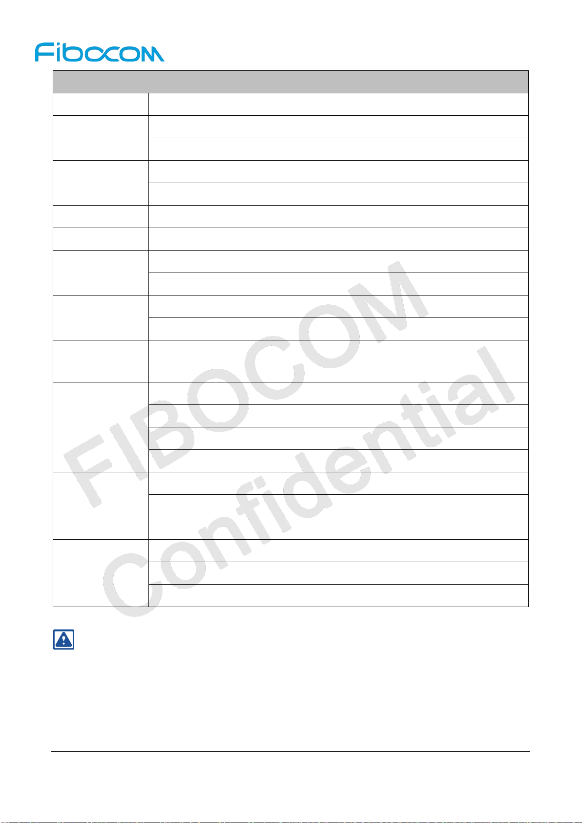
FIBOCOM H330S Hardware User Manual Page 2 of 49
support Support
No
Support
No
Support
7.2 5.76
GSM/GPRS/EDGE
WCDMA
Type
Band(MHz)
Band(MHz)
H330S-Q30-10 850/900/1800/1900 850/900/1900/2100
Audio
Analog Digital
No
Support 7.2 5.76
Support
HSDPA
(Mbps)
HSUPA
(Mbps)
Reproduction forbidden without Fibocom Wireless Inc. written authorization - All Rights Reserved.
FIBOCOM H330S Hardware User Manual Page 3 of 49
Copyright
Copyright ©2018 Fibocom Wireless Inc . All rights reser ved.
Without the prior written permission of the copyright holder, any company or individual is prohibi ted to
excerpt, copy any part of or the entire document, or t r ansm it t he doc ument in any form.
Attention
The document is subject to update from time to time owing to the product version upgrade or other
reasons. Unless otherwise specified, the document only serves as the user guide. All the statements,
information and suggestions contained in the document do not constitute any explicit or implicit
guarantee.
Trademark
The trademark is registered and owned by Fibocom Wireless Inc.
Reproduction forbidden without Fibocom Wireless Inc. written authorization - All Rights Reserved.
FIBOCOM H330S Hardware User Manual Page 4 of 49
Versions
Version Date Remarks
V1.1.1 2015-01-30 Update the range of operating temperatur e.
V1.1.2 2015-04-21 Add the description of “Top View” in PCB Layout
Update the description of copyright and attention.
V1.1.3 2015-05-10
Update the translation o f the w hole document.
V1.1.4 2015-07-27 Update the info of H330S and the logo.
V1.1.5 2015-09-22 Update the 12C and 12S descript io n of H330S-XXX-20
V1.1.6 2015-11-17 Update the maximum operating voltage to 4.2V
V1.1.7 2016-06-17 Add the H330S-Q30-20
V1.1.8 2016-11-29 Modify the description of VSPK
V1.1.9 2016-12-08 Add the H330-A30-80
V1.2.0 2016-12-30 Add the H330S-Q30-10,H330S-A30-90
V1.2.1 2018-04-28 Add the H330S-Q30-90
Update 1.2 Reference Standards
Delete 5.1.3 VIO, add 5.1.2 Logic Level
V1.2.2 2018-12-22
Add 5.1.3 Power Consum pt ion Max Value, update Typical Valu e
Add 7.2 Transmitting Power and 7.3 Receiver Sensitivity
Reproduction forbidden without Fibocom Wireless Inc. written authorization - All Rights Reserved.
FIBOCOM H330S Hardware User Manual Page 5 of 49

Contents
1 Foreword ............................................................................................................................................... 12
1.1 Introduction ................................................................................................................................... 12
1.2 Reference S t an dard s .................................................................................................................... 12
2 Product Overview ................................................................................................................................. 14
2.1 Description .................................................................................................................................... 14
2.2 Specifications ................................................................................................................................ 14
2.3 Appearance ................................................................................................................................... 16
3 Structure ............................................................................................................................................... 17
3.1 Dimension Diagram of Structure ................................................................................................... 17
3.2 PCB Layout Design ....................................................................................................................... 17
4 Hardware Introduction .......................................................................................................................... 18
4.1 Hardware Block Diagram .............................................................................................................. 18
4.2 Pin Definition ................................................................................................................................. 19
4.2.1 Pin Map ............................................................................................................................... 19
4.2.2 Description of Pin s .............................................................................................................. 19
5 Hardware Interface ............................................................................................................................... 26
5.1 Power Interface ............................................................................................................................. 26
5.1.1 Power Supply ...................................................................................................................... 26
5.1.2 Logic level ........................................................................................................................... 26
5.1.3 Power Consumption ........................................................................................................... 27
5.1.4 VRTC .................................................................................................................................. 29
5.2 Power on/off a nd Reset Signal
5.2.1 Pin Definition of Power on/off Control Sign al ..................................................................... 30
5.2.2 Power on Signal.................................................................................................................. 30
5.2.3 Power off Sig nal .................................................................................................................. 31
5.2.4 Reset Signal ....................................................................................................................... 32
..................................................................................................... 30
5.3 St atus Indicat ing Sign al................................................................................................................. 33
5.3.1 LPG Signal .......................................................................................................................... 33
5.3.2 SMI Signal .......................................................................................................................... 34
5.3.3 WAKE_UP Signal ............................................................................................................... 34
5.3.4 Other Work Indications ....................................................................................................... 34
5.4 USB Interface ................................................................................................................................ 35
Reproduction forbidden without Fibocom Wireless Inc. written authorization - All Rights Reserved.
FIBOCOM H330S Hardware User Manual Page 6 of 49

5.4.1 USB Interface Definition ..................................................................................................... 35
5.4.2 USB Interface Application ................................................................................................... 35
5.5 UART Interface ............................................................................................................................. 36
5.5.1 UART Int erface Des cripti on ................................................................................................ 36
5.5.2 UART Interface Applicati on ................................................................................................ 37
5.5.3 Ring Indication .................................................................................................................... 38
5.6 USIM Interface .............................................................................................................................. 38
5.6.1 USIM Pins ........................................................................................................................... 38
5.6.2 USIM Design ....................................................................................................................... 39
5.6.3 Points for Attention in USIM Design ................................................................................... 39
5.6.4 USIM Hot-Plugging ............................................................................................................. 40
5.6.4.1 Hardware Connection .............................................................................................. 40
5.6.4.2 Software S ettings ..................................................................................................... 40
5.7 Analog Audio Interface ................................................................................................................. 41
5.7.1 Definition of Audio Interface Signals .................................................................................. 41
5.7.2 Description of Audio Interface Application .......................................................................... 41
5.7.2.1 Audio Channel 1 ....................................................................................................... 42
5.7.2.2 Audio Channel 2 ....................................................................................................... 42
5.8 Digital Audio .................................................................................................................................. 43
5.8.1 I2S ....................................................................................................................................... 43
5.8.2 I2C ...................................................................................................................................... 43
5.8.3 PCM Port Description ......................................................................................................... 44
5.9 ADC Interface ................................................................................................................................ 44
5.10 Other Interfaces .......................................................................................................................... 44
6 Electrical and Environmental Features ................................................................................................. 45
6.1 Electrical Features ........................................................................................................................ 45
6.2 Environmenta l Fe atures ................................................................................................................ 45
7 RF Interface .......................................................................................................................................... 45
7.1 Operating Frequenc y Band ........................................................................................................... 45
7.1.1 Frequency Range o f M ain Antenna .................................................................................... 45
7.2 T rans mitt ing Power ....................................................................................................................... 46
7.3 Receiver Sensitivity ....................................................................................................................... 46
7.4 RF PCB Design ............................................................................................................................. 47
7.4.1 Wiring Principle ................................................................................................................... 47
Reproduction forbidden without Fibocom Wireless Inc. written authorization - All Rights Reserved.
FIBOCOM H330S Hardware User Manual Page 7 of 49

7.4.2 Impedance Design .............................................................................................................. 47
7.5 Antenna Design ............................................................................................................................. 47
7.5.1 Main Antenna Design Requir ements .................................................................................. 47
7.5.1.1 Antenna effici ency .................................................................................................... 47
7.5.1.2 S11 or VSWR ........................................................................................................... 48
7.5.1.3 Polarization ............................................................................................................... 48
7.5.1.4 Radiation patt ern ...................................................................................................... 48
7.5.1.5 Gain and directiv ity ................................................................................................... 48
7.5.1.6 Interference .............................................................................................................. 48
7.5.1.7 TRP/TIS .................................................................................................................... 49
Reproduction forbidden without Fibocom Wireless Inc. written authorization - All Rights Reserved.
FIBOCOM H330S Hardware User Manual Page 8 of 49

Federal Communication Commission
Interference Statement
This device complies with Part 15 of the FCC Rules. Operation is subject to the following two conditions:
(1) This device may not cause harmful interference, and (2) this device must accept any interference
received, including interf erence that may cause undesired operation.
This equipment has been tested and found to comply with the limits for a Class B digital device, pursuant
to Part 15 of the FCC Rul es. These limits are designed t o pr ovide re ason ab le prot ecti on agai nst har mful
interference in a residential installation. This equipment generates, uses and can radiate radio frequency
energy and, if not installed and used in accordance with the instructions, may cause harmful interference
to radio communications. However, there is no guarantee that interference will not occur in a particular
installation. If this equipment does cause harmful interfer ence to radio or t elevision recepti on, w hich can
be determined by turning the equipment off and on, the user is encouraged to try to correct the
interference by one of the following measures:
Reorient or relocate the receiving anten na.
Increase t he separation betw een t he equipment and receiver.
Connect the equipment into an outlet on a circuit different from that to which the receiver is
connected.
Consu lt t he dealer or an experienced radio/TV technician for help.
FCC Caution:
Any changes or modifications not expressly approved by the party responsible for compliance could
void the user's authority to operate this equipment.
This transmitter must not be co-located or operating in conjunction with any other antenna or
transmitter.
Reproduction forbidden without Fibocom Wireless Inc. written authorization - All Rights Reserved.
FIBOCOM H330S Hardware User Manual Page 9 of 49
Radiation Exposure Statement:
This equipment complies with FCC radiation exposure limits set forth for an uncontrolled environment.
This equipment should be installed and operated with minimum distance 20cm between the radiator &
your body.
This device is intended only for OEM integrators under the following conditions:
1) The antenna must be installed such that 20 cm is maintained between the antenna and
users, and the maximum antenna gain allowed for use with this device is -1 dBi.
2) The transmitter module may not be co-located with any other transmitter or antenna.
As long as 2 conditions above are met, further transmitter test will not be required. However, the OEM
integrator is still responsible for testing their end-product for any additional compliance requirements
required with this module installed
IMPORTANT NOTE: In the event that these conditions can not be met (for example certain laptop
configurations or co-location with another transmitter), then the FCC authorization is no longer considered
valid and the FCC ID can not be used on the final product. In these circumstances, the OEM integrator will
be responsible for re-evaluating the end product (including the transmitter) and obtaining a separate FCC
authorization.
End Product Labeling
This transmitter module is authorized only for use in device where the antenna may be installed such that
20 cm may be maintained between the antenna and users. The final end product must be labeled in a
visible area with the following: “Contains FCC ID: ZMOH330S”. The grantee's FCC ID can be used only
when all FCC compliance requirements are met.
Manual Information To the End User
The OEM integrator has to be aware not to provide information to the end user regarding how to install or
remove this RF module in the user’s manual of the end product which integrates this module. The end
user manual shall include all required regulatory information/warning as show in this manual.
Reproduction forbidden without Fibocom Wireless Inc. written authorization - All Rights Reserved.
FIBOCOM H330S Hardware User Manual Page 10 of 49

Innovation, Science and Economic
Development Statement
This device complies with ISED Innovation, Science and Economic Development license-exempt
RSS standard(s). Operation is subject to the following two conditions:
1) this device may not cause interference, and
2) this device must accept any interference, including interference that may cause undesired
operation of the device.
Le présent appareil est conforme aux CNR d'Industrie Canada applicables aux appareils radio
exempts de licence. L'exploitation est autorisée aux deux conditions suivantes:
1) l'appareil ne doit pas produire de brouillage, et
2) l'utilisateur de l'appareil doit accepter tout brouillage radioélectrique subi, même si le brouillage
est susceptible d'en compromettre le fonctionnement.
This Class B digital apparatus complies with Canadian ICES-003.
Cet appareil numérique de la classe B est conforme à la norme NMB-003 du Canada.
This device and its antenna(s) must not be co-located or operating in conjunction with any other
antenna or transmitter, except tested built-in radios.
Cet appareil et son antenne ne doivent pas être situés ou fonctionner en conjonction avec une autre
antenne ou un autre émetteur, exception faites des radios intégrées qui ont été testées.
The County Code Selection feature is disabled for products marketed in the US/ Canada.
La fonction de sélection de l'indicatif du pays est désactivée pour les produits commercialisés aux
États-Unis et au Canada.
Radiation Exposure Statement:
This equipment complies with IC radiation exposure limits set forth for an uncontrolled environment.
This equipment should be installed and operated with minimum distance 20cm between the radiator &
your body.
End Product Labeling:
This transmitter module is authorized only for use in device where the antenna may be installed such
that 20 cm may be maintained between the antenna and users. The final end product must be labeled in
a visible area with the following: “Contains IC: 21374-H330S”. The grantee's IC can be used only when
all ISED compliance requirements are met.
Antenna Requirements:
Antenna Design of this document.Generally,50 ohm impedance is required and S11 is recommended
less than -10 dB,the recommended antenna gain should be no bigger than 2.5 dBi.Antenna types that
do not meet these requirement are strictly prohibited for use with this device.
FIBOCOM H330S Hardware User Manual Page 11 of 49
This transmitter module(IC:21374-H330S) requires antennas of specifications of Chapter 7.5
Reproduction forbidden without Fibocom Wireless Inc. written authorization - All Rights Reserved.

1 Foreword
1.1 Introduction
The document describes the electrical characteristics, RF performance, dimensions and application
environment, etc. of H330S series wireless modules. With the assistance of the document and other
instructions, developers can quickly understand the performance of H330S series wireless modules and
develop products.
1.2 Reference Standards
The design of the product co mp lie s w it h t he f ollowing standards:
3GPP TS 27.007 -v6.9.0: AT command set for User Equipment ( UE)
3GPP TS 27.005 -v6.0.1: Use of Data Terminal Equipment -Data Circuit terminating Equipment
(DTE-DCE) interface for Short Message Service (SMS) and Cell Broad cast Service (CBS)
3GPP TS 23.040 -v6.9.0: Technical realization of Short Message Service (SMS)
3GPP TS 24.011 -v6.1.0: Point- to - Point (PP) Short Message Service (SMS) support on m obile
radio interface
3GPP TS 27.010 -v6.0.0: Terminal Equipment to User Equip m ent ( TE-UE) multiplexer protocol
3GPP TS 27.060 -v6.0.0: Packet domain; Mobile S t ation (MS) supp orting Pa cket Switched s ervices
3GPP TS 25.304-v6.10. 0: User Equipment (UE) procedures in idle mode and procedures for cell
reselection in connected mo de
3GPP T S 34.121-1 V7.5.0: Technical Sp ecif ication ; Rad io trans miss ion an d recept ion ( FD D); Part 1:
Conformance specificat i on
3GPP TS 25.308 -v6.4.0: High Speed Down link Packet Access (HSDPA); Overall description;
Stage 2
3GPP TS 25.309 -v6.6.0: FDD enhanced uplink; Overall description; Stage 2
3GPP TS 23.038 -v6.1.0: Alphabets and language - specific information
3GPP TS 21.111 -v6.3.0 : USIM and I C c ar d r equirements
3GPP TS 31.111 -v6.1 1. 0 "USIM Application Toolkit (USAT)"
3GPP TS 45.002 -v6.12.0: Multiplexing and multiple access on t he r adio path
3GPP TS 51.014 -v4.5.0: Specification of the SI M Application Toolkit for the Subscriber Identity
Module - Mobile Equipment (SIM-ME) interface
Reproduction forbidden without Fibocom Wireless Inc. written authorization - All Rights Reserved.
FIBOCOM H330S Hardware User Manual Page 12 of 49

3GPP TS 51.010 -1 -v6.7.0: Mobile Station (MS) confor man c e specification; Part 1: Conform ance
specification
3GPP TS 22.004 -v6.0.0: General on supplementary services
3GPP TS 23.090 -v6.1.0: Unstructured Supplementar y Service Data (USSD); Stage 2
3GPP TS 24.008 v6.19, Mobile radio interface Layer 3 specif ication;
Reproduction forbidden without Fibocom Wireless Inc. written authorization - All Rights Reserved.
FIBOCOM H330S Hardware User Manual Page 13 of 49
2 Product Overview
2.1 Description
H330S series modules are 3G wireless modules with high integration density, supporting GSM/GPRS/
EDGE and UMTS/HSDPA/HSUPA/HSPA+.
2.2 Specifications
Specifications
Operating
Frequency
Range
Data Rate
Operating
Voltage
Physical
Characteristics
UMTS (WCDMA/FDD): 850/900/1900/2100 MHz or 900/21 00MHz
GSM/GPRS/EDGE: 850/900/1800/1900 MHz or 900/ 1800MHz
UMTS/HSDPA/HSUPA 3G PP release 7
HSUPA 5.76Mbps (Cat 6)
HSDPA 21Mbps (Cat 14) or 7.2Mbps (Cat 8)
GSM 3GPP release 7
EDGE (E-GPR S) mu lti-slot class 33 (296kbps DL, 2 36. 8kbps UL)
GPRS multi-slot class 33 (107kbps DL, 85.6kbps UL )
Voltage: 3.3V ~ 4.2V Typical: 3.8V
Dimension: 33.8 x 27.8 x 2. 45mm
Interface: LGA
Weight: About 5.5 g
Normal operating Temperature: -30℃ ~ +7 5 ℃
Environment
Interfaces
Rf Interface Main Antenna
Function
Interface
Reproduction forbidden without Fibocom Wireless Inc. written authorization - All Rights Reserved.
FIBOCOM H330S Hardware User Manual Page 14 of 49
Restricted operating temperature①: -40℃ ~ + 8 5℃
Storage Temperature: -40℃ ~ + 8 5℃
1 x USB 2.0,2 x UART,MUX Over UART1,Multiple Profiles over USB
SPI Support (Not supported yet),I2C Support②,I 2S S upport②
HSIC,GPIO,A/D,RTC
Data Features
Protocol Stack Embedded TCP/IP and UDP/IP protocol stack
Multi-slot class 33(5 Down; 4 Up; 6 Total)
EDGE
Coding Scheme MCS1~9
Multi-slot class 33(5 Down; 4 Up; 6 Total)
GPRS
Coding Scheme CS1~4
CSD UMTS(14.4kbps), GSM(9.6kbps)
USSD Support
MO / MT Text and PDU modes
SMS
Cell broadcast
Analog Audio and Digital Audio
②
Audio
Voice coders: EFR/HR/FR/AMR
Audio Frequenc y
Control
Character Set
AT Commands
Accessories
Gain Control, Echo Cancellation, Noise Suppression, Sideto ne
IRA
GSM
UCS2
HEX
FIBOCOM proprietary AT c ommands
GSM 07.05
GSM 07.07
Firmware Loader Tool over USB/UART
User Manual
Developer Kit
Note
:
①
: For the temperat ure is out of the norm al tempera ture range: -30℃ ~ +75, some indexes may
slightly deviate from the related 3GPP codes.
②:H330S-XXX-20 serials module does not support Audio.
H330S-XXX-10 serials module supp or t Di gital Audio, and does not support Analog Audio.
Reproduction forbidden without Fibocom Wireless Inc. written authorization - All Rights Reserved.
FIBOCOM H330S Hardware User Manual Page 15 of 49

2.3 Appearance
The product appearance of H330S series wireless mo dule is shown as below:
Top view:
Bottom view:
Figure 2-1 Top View
Figure 2-2 Bottom View
Reproduction forbidden without Fibocom Wireless Inc. written authorization - All Rights Reserved.
FIBOCOM H330S Hardware User Manual Page 16 of 49

3 Structure
3.1 Dimension Diagram of Structure
Figure 3-1 Dimension Dia gra m of S tr ucture
3.2 PCB Layout Design
Figure 3-2 Recommended PCB Layout(Top View)
Reproduction forbidden without Fibocom Wireless Inc. written authorization - All Rights Reserved.
FIBOCOM H330S Hardware User Manual Page 17 of 49

JTAG
I2S
SPI
USIF
USB HS
ARM1176
MIPI HSI
PCM
32KHz XO
Ext. Memory
Interface
PMU
Digital RF
Interface
I2C
Audio DSP
2G Layer1
DSP/Timer
3G/HSPA
Layer1
Memories(ARM,ROM,cache)
MCP
Nand 1Gb + DDR
256Mb
1
2
0
-
p
i
n
L
G
A
C
o
n
n
e
c
t
o
r
I
n
t
e
r
f
a
c
Dig RF
v3.09
Control
DAC
RX
Diversity
VCTCXO
FE
Control
2G/3G
TX
2G/3G
RX
Main
Duplexer
PA Power
Management
RFPA
Main
Antenna
Switch
Module
SPI
Diversity
Duplexer
Diversity
Antenna Switch
Module
CLK
CLK in
Power Supply 3.3~4.2V
UART
USB
SPI
I2S
I2C
PCM
USIM
USIM
JTAG
VBACKUP
SMARTi-UE2
PMB 5712
X-Gold 62xx
PMB 98xx
Audio Codec
EAR +/-
MIC +/-
AUXO +/-
AUXI +/-
Vspeaker
Power_on
Reset_ALL_N
Reset_PMU_N
LDO
Output:1.8V
Ant_div
Ant_main
H330S Module:
GSM/GPRS/EDGE,WCDMA
ADC/DAC
MIPI
MMC
MMC
4 Hardware Introduction
4.1 Hardware Block Diagram
FIBOCOM H330S Hardware User Manual Page 18 of 49
Figure 4-1 Block Diagram
Reproduction forbidden without Fibocom Wireless Inc. written authorization - All Rights Reserved.

4.2 Pin Definition
4.2.1 Pin Map
TOP (View)
Figure 4-2 Pin Diagram
4.2.2 Description of Pins
The logic signal lever of H330S series is 1.8V. Pins of H330S series are described in t he table below:
Reproduction forbidden without Fibocom Wireless Inc. written authorization - All Rights Reserved.
FIBOCOM H330S Hardware User Manual Page 19 of 49

Reset
Pin # Pin Name I/O
Value
Idle
Description
Value
Power Supply
59 VBAT I
60 VBAT I
61 VBAT I
Main power supply, voltage range: 3.3V ~
4.2V.
62 VBAT I
Test pin for power supply of RF power
64 VPA O
amplifier .Idle state in a ctual use.
Test pin for transceiver power supply .
1 VTRX O
Idle state in actual use
46 VIO O 1.8V voltage output inside the modules.
47 VRTC I/O Backup battery input/output.
Power ON/OFF Signal
Power off control signal, internal 4.7K
48 POWER_OFF I PU PU
pull-up resistor
Power on control signal, int ernal 200K
49 POWER_ON I PU PU
pull-up resistor
Reset Signal
External reset signal input, internal 200K
77 RESET_ALL_N I PU PU
pull-up resistor
USIM Interface
Insert USIM card to test; active low;
4 USIM_CD I PU PU
Internal 390K pull-up resis t or .
5 USIM_VCC O USIM card power supply: 1.8V or 3.0V
6 USIM_RST O PP PP USIM card reset signal.
7 USIM_CLK O PP PP USIM card clock signal.
USIM card data signal, inter nal 4. 7K
8 USIM_DATA I/O PU PU
pull-up resistor.
High Speed SIM Interface
Reproduction forbidden without Fibocom Wireless Inc. written authorization - All Rights Reserved.
FIBOCOM H330S Hardware User Manual Page 20 of 49

Reset
Pin # Pin Name I/O
Value
Idle
Description
Value
High speed SIM card USB signal +
9 USIM_D+
(Temporarily not supported)
High speed SIM card USB signal 10 USIM_D-
(Temporarily not supported)
Audio Interface
13 AUXO+ O Speaker output signa l +
14 AUXO- O Speaker output signa l 15 EAR- O Earphone signal output 16 EAR+ O Earphone signal output +
17 MIC+ I Main MIC input signal +
18 MIC- I Main MIC input signal 19 AUXI- I Auxiliary MIC inpu t signal 20 AUXI+ I Auxiliary MIC input signal +
21 AGND GND Analog GND
Power supply input for the inter nal power
22 VSPK I
amplifier of audio codec c hip,
Advise to connect VBAT.
I2S
11 I2S2_CLK1 O PD PD I2S2 serial clock SCLK1
24 I2S2_CLK0 O T T I2S2 serial clock SCLK0 (Default: CLK0)
25 I2S2_WA0 O T T I2S2 field selection signal
26 I2S2_TX O T T I2S2 serial data output
27 I2S2_RX I T T I2S2 serial data input③
USB
31 USB_DP I/O USB data signal+
32 USB_DM I/O USB data signal33 USB_ID — USB ID signal
34 VUSB I USB Power Input
Reproduction forbidden without Fibocom Wireless Inc. written authorization - All Rights Reserved.
FIBOCOM H330S Hardware User Manual Page 21 of 49

Reset
Pin # Pin Name I/O
Value
Idle
Description
Value
92 USB_TEST — USB TEST signal
I2C
I2C data signal line, Internal 1K pull-up
28 I2C_SDA I/O PU PU
resistor
③
I2C clock signal line, Inter nal 1 K pull-up
29 I2C_SCL O PU PU
resistor.
UART1
35 UART1_RI O L L UART1 Ring Indicator
36 UART1_DSR I T T UART1 DTE Ready
37 UART1_DTR O H H UART1 DCE Ready
38 UART1_DCD O L L UART1 Carrier Detect
39 UART1_CTS I PU PU UART1 Clear To Send
40 UART1_RTS O L L UART1 Request To Send
41 UART1_TXD O PP PP UART1 Transmitted Data
42 UART1_RXD I PU PU UART1 Received Data
UART2
45 UART2_TXD O PP PP UART2 Transmitted Data
44 UART2_RXD I PU PU UART2 Received Data
ADC
50 ADC2 I ADC2, input voltage range:0~1.2V
51 ADC1 I ADC1, input voltage range:0~1.2V
EINT
56 WAKE_UP I PU PU Interrupt of external wake-up, active low.
57 EINT2 I PU PU External interrupt, ac t iv e low.
USB HSIC
HSIC USB data signal line
90 HSIC_USB_DATA
(not supported)
91 HSIC_USB_STRB HSIC USB pulse signal line
Reproduction forbidden without Fibocom Wireless Inc. written authorization - All Rights Reserved.
FIBOCOM H330S Hardware User Manual Page 22 of 49

Reset
Pin # Pin Name I/O
Value
Idle
Description
Value
(not supported)
Antenna
Main antenna interface,i m pedance
67 ANT_MAIN I
requirement: 50 ohm.
71 ANT_DIV I Only supported by some models
Others
GPIO . Used for HSIC IPC in special
3 DSP_AUDIO_IN1 O H H
software versions
54 CLKOUT0 O PP PP Digital audio clock output
89 SMI O L Sleep Mode Indicator
86 LPG O Status indicator
NC
23 NC
55 NC
52 NC
53 NC
73 NC
74 NC
75 NC
76 NC
78 NC
79 NC
80 NC
81 NC
82 NC
83 NC
84 NC
85 NC
Reproduction forbidden without Fibocom Wireless Inc. written authorization - All Rights Reserved.
FIBOCOM H330S Hardware User Manual Page 23 of 49

Reset
Pin # Pin Name I/O
Value
Idle
Description
Value
87 NC
88 NC
94 NC
95 NC
96 NC
101 NC
105 NC
106 NC
107 NC
108 NC
GND
2 GND
12 GND
30 GND
43 GND
58 GND
63 GND
65 GND
66 GND
68 GND
69 GND
70 GND
72 GND
93 GND
97 GND
98 GND
99 GND
100 GND
Reproduction forbidden without Fibocom Wireless Inc. written authorization - All Rights Reserved.
FIBOCOM H330S Hardware User Manual Page 24 of 49

Reset
Pin # Pin Name I/O
Value
Idle
Description
Value
102 GND
103 GND
104 GND
109 GND
110 GND
111 GND
112 GND
113 GND
114 GND
115 GND
116 GND
117 GND
118 GND
119 GND
120 GND
H:High Voltage Level
L:Low Voltage Level
PD:Pull-Down
PU:Pull-Up
T:Tristate
OD:Open Drain
PP:Push-Pull
:
Note
③: the pin28(I2C_SDA) and pin27(I2S2_RX) of the H330S-XXX-20 series is float ing, please don
not use.
Reproduction forbidden without Fibocom Wireless Inc. written authorization - All Rights Reserved.
FIBOCOM H330S Hardware User Manual Page 25 of 49

5 Hardware Interface
5.1 Power Interface
5.1.1 Power Supply
H330S modules require 3.3V~4.2V direct current power supply, which can provide the maximum GSM
emission current of 2A.
Input power supply requirem ents:
Parameter Minimum Value Recommended Valu e Maximum Value Unit
VBAT 3.3 3.8 4.2 V
Points for attention in d es i gn:
1. Supply voltage fluctuation shall be lower than 300m V.
2. Minimum supply voltage drop shall be higher than 3. 3V.
Filter capacitor of supply circuit is designed as follows:
Recommended
capacitor
1000uF Supply capacitance
10nF, 100nF Digital signal noise
8.2pF, 10pF 1800/1900/2100 MHz Filter RF interference
33pF, 39pF 850/900 MHz Filter RF interference
Application Description
Reduce power-supply fluctuation during phone call.
The capacitance value big ger is better
Filter the interference caused by clock and digital
signals
5.1.2 Logic level
As the power supply for the digital circuit inside the module, VIO can be used as the st at us indicator and
digital signals reference level of the module.
The H330S module 1.8V logic level definition as shown in the fo l low i ng table:
Parameters Minimum Typical Maximum Unit
1.8V logic level 1.773 1.8 1.827 V
Reproduction forbidden without Fibocom Wireless Inc. written authorization - All Rights Reserved.
FIBOCOM H330S Hardware User Manual Page 26 of 49

RTC mode
uA
WCDMA
DRX
5
DRX
9
DRX
6
DRX
8
DRX
9
Radio Off
AT+CFUN=4,Flight mode
1 TX slot
10
19
5
10
19
0
5
15
0
5
15
5
mA
Parameters Minimum Typical Maximum Unit
VIH 1.3 1.8 1.89 V
VIL -0.3 0 0.3 V
5.1.3 Power Consumption
Parameter Description Condition Typical Value Max Value Unit
I
OFF
67 80
I
IDLE
I
SLEEP
I
GSM-RMS
GSM
Idle mode
14.3 18
mA
14.8 18
DRX 2
2.5 5
Low power
mode(GSM)
2.1 5
2.0 5
Low power
mode(WCDM
2.9 5
2.3 5
mA
A)
2.2 5
2.1 3
5
300 360
GSM850
PCL
110 160
65 120
310 380
EGSM900
PCL
GSM voice -
1 Rx slot
110 160
65 120
mA
260 300
DCS1800
PCL
120 150
I
GPRS-RMS
FIBOCOM H330S Hardware User Manual Page 27 of 49
Reproduction forbidden without Fibocom Wireless Inc. written authorization - All Rights Reserved.
PCS1900
PCL
GPRS Class GSM850
90 120
260 300
120 150
90 120
520 560

33 -
PCL
10
5
10
0
10
0
10
8
15
8
15
2
10
2
10
5
10
5
10
0
5
0
5
22.5dBm
0dBm
22.5dBm
0dBm
22.5dBm
0dBm
Parameter Description Condition Typical Value Max Value Unit
260 300
4 TX slot
1 Rx slot
EGSM900
PCL
540 580
260 300
I
EGPRS-RMS
EGPRS
Class 33 4 TX slot
1 Rx slot
DCS1800
PCL
PCS1900
PCL
GSM850
PCL
EGSM900
PCL
DCS1800
PCL
PCS1900
PCL
GSM850
PCL
360 400
125 150
390 420
125 160
600 650
140 180
580 620
160 200
mA
385 420
135 180
575 620
135 180
2100 2300
540 700
EGSM900
PCL
DCS1800
I
GSM-MAX
Peak current
During TX
slot
PCL
PCS1900
PCL
Band5
(850)
I
WCDMA-RMS
WCDMA
Band2
(1900)
Band1
(2100)
Reproduction forbidden without Fibocom Wireless Inc. written authorization - All Rights Reserved.
FIBOCOM H330S Hardware User Manual Page 28 of 49
2200 2400
600 700
mA
1550 1700
540 700
1600 1800
540 700
535 560
170 200
670 700
mA
170 200
700 730
170 200

22.5dBm
0dBm
Parameter Description Condition Typical Value Max Value Unit
Band8
(900)
605 650
165 200
Note:
The data above is an aver age value obtained by testing some samples.
5.1.4 VRTC
VRTC is the power supply of the RTC inside the mo dul e, and it can be used as the backup power signal
as well.
Parameters Minimum Value Recommended Value Maximum Value Unit
VRTC output voltage 1.71 1.8 1.89 V
VRTC input voltage
0.5 1.8 1.89 V
(RTC is in normal)
VRTC input current
1.0 uA
(RTC is in normal)
The reference design of VRTC circuit is as follows:
Figure 5-1 VRTC Reference Design
Note:
R8 is a current-limiting resistor, used to ensure the VRTC module works properly, free from
being affected by peripheral circuits. R8≥1k ohm
VRTC power consumption current<1uA
Reproduction forbidden without Fibocom Wireless Inc. written authorization - All Rights Reserved.
FIBOCOM H330S Hardware User Manual Page 29 of 49

VBAT
POWER_ON
VDD_1V8
300mS
8mS
The value of C9 will affect the retaining time of RTC after VBAT powers off. The retaining
time of RTC can be roug hl y calculated by the following for m ul a:
T= (1.8-0.5)*C/1=1.3C, unit: second. Namely, if the value of C9 is 100uF, the retaining tim e of
RTC will be around 130s.
5.2 Power on/off and Reset Signal
5.2.1 Pin Definition of Power on/off Control Si gnal
H330S wireless modules provide three control signals to start up, shut down, and reset the modules.
Pins definition as listed be low :
Pin# Pin Name Electrical Level Description
48 POWER_OFF CMOS 1.8V Power off signal
49 POWER_ON CMOS 1.8V Power on signal
77 RESET_ALL_N CMOS 1.8V External reset signal input
5.2.2 Power on Signal
After the module is con nected to the power supply, the user can start up the module by setting low
POWER_ON signal low.
Timing seq uence requirement of the start up pulse:
Parameter Minimum Value Typical Value Maximum Value Unit
Pulse Width 100 300 3000 ms
The timing sequence cont r ol is s hown in the diagram below:
Figure 5-2 Timing Control
FIBOCOM H330S Hardware User Manual Page 30 of 49
Reproduction forbidden without Fibocom Wireless Inc. written authorization - All Rights Reserved.

VBAT
POWER_OFF
VDD_1V8
300mS
The recommended design of POWER_ON signal is as follows:
Figure 5-3 POWER_ON R eference De sign
5.2.3 Power off Signal
When setting POWER_OFF signal low, the module’s PMU (P ower Ma nageme nt Unit) w ill be r eset. Then,
the module will turn to shutdown state from operation state. The timing sequence requirements of the
pulse are as follows:
Parameter Minimum Value Typical Value Maximum Value Unit
Pulse Width 100 300 3000 ms
The timing sequence cont r ol is s hown in the diagram below:
Figure 5-4 Timing Control
The recommended design of POWER_OFF signal is as follows:
FIBOCOM H330S Hardware User Manual Page 31 of 49
Reproduction forbidden without Fibocom Wireless Inc. written authorization - All Rights Reserved.

Figure 5-5 POWER_OFF Reference Design
5.2.4 Reset Signal
H330S wireless modules support external reset function. It is feasible to reset the module back to the
original state by the Res et Sig nal.
When setting the Reset Signa l low f or 100 ms, t he modu le will be re set and res t arted. When the user us e s
the Reset function, the P MU in side the module will not lose power.
Note:
Reset signal is a sensitive signal line. In designing PCB layout , ple ase keep the line away from R F
interference, and make it well wrapped with ground wire. And it is advised to add an anti-shaking
capacitor at the place c los e to the module end.
The timing sequence requ irements of its pulse ar e as follows:
Parameters Minimum Value Typical Value Maximum Value Unit
Pulse Width 100 300 3000 ms
Recommended design:
Reproduction forbidden without Fibocom Wireless Inc. written authorization - All Rights Reserved.
FIBOCOM H330S Hardware User Manual Page 32 of 49

Figure 5-6 Reset Reco m me nded Design
5.3 Status Indicating Signal
The pins of status indic at ing signal as listed below:
Pin# Pin Name Description
86 LPG Status indicating
89 SMI Sleep St atus ind icat ing
56 WAKE_UP Sleep wake-up pin
1 VTRX Transceiver power supply signal, indicating the power status of the transceiver
64 VPA Power supply signal of R F power amplifier
5.3.1 LPG Signal
LPG signal description as listed below:
Status Mode
idle(unregistered) 600ms high level, 600ms low level
idle(registered) 75ms high level, 3S low level
Voice c ommunication (Call) low level
Data communicating 75ms high level, 75ms low level
Sleep (sleep mode) hig h level
Note:
High level voltage is 1.8V.
Reproduction forbidden without Fibocom Wireless Inc. written authorization - All Rights Reserved.
FIBOCOM H330S Hardware User Manual Page 33 of 49

largest power; 0V in the case of no transmission
5.3.2 SMI Signal
SMI signal description as l ist ed below :
Modes Description
Sleep Mode 2.5S High; 100ms Low,repeat this
Other Mode low level
5.3.3 WAK E_UP Signal
WAKE_UP is for waking up the module from Sleep mode, it is high level by default, but low level is
activated.
Module Mode WAKE_UP Sig n al Description
Low level Wake up the module from Sleep mode to Idle mode
Sleep
High level Keep the module in Sleep mode
Idle/Call Low/High level Keep the module in Idl e/ Call mode
When the module is in Sleep mode, the function of EINT1/WAKE_UP signal is as fo ll ow s:
When EINT1/WAKE_UP is at low level under the control of MCU GPIO, it will wake up the module to idle
mode.
When EINT1/WAKE_UP is at high level under the control of MCU GPIO, it will keep the module in sleep
mode.
5.3.4 Other Work Indications
Pin Name Electrical Level Description
VTRX 1.8V Work indication of RF Transceiver PMU
VPA 0-5V
In transmission, output V CC; 0.65V at the lowest power; 5V at t he
Note:
It is only used for indicating w or k conditions. Keep it in the idle state in actual use. It cannot be
used for other purposes.
Reproduction forbidden without Fibocom Wireless Inc. written authorization - All Rights Reserved.
FIBOCOM H330S Hardware User Manual Page 34 of 49

5.4 USB Interface
5.4.1 USB Interface De finition
Pin# Pin Name I/O Description
31 USB_DP I/O USB signal+
32 USB_DM I/O USB signal33 USB_ID — USB ID signal (NC is recommend ed)
34 VUSB I USB power input
92 USB_TEST — USB TEST signal(NC is recommended)
H330S wireless modules supp ort US B 2.0. Be for e conne ct ing it t o PC, it is ne cessar y t o inst a ll the relat ed
USB driver.
After inserting the H330S wireless modules to PC, the USB interface will work with the driver and map
seven ports on PC, as fo ll ow s:
One 3G Modem/ AT port for initiating data traffic
Three port s f or dispatching AT Command
Two ports for capturing LOG information of the software
One port reserv ed for future use
5.4.2 USB Interface A pplicatio n
Reference Circuit Design:
Figure 5-7 USB Interface Refere nce Circuit Design
Reproduction forbidden without Fibocom Wireless Inc. written authorization - All Rights Reserved.
FIBOCOM H330S Hardware User Manual Page 35 of 49

T101 and T102 shall be TVS with capacitance lower than 1pF; there is no specific limitation for the
capacitance of T103.
VUSB pin supplies power for USB. The recommended power supply range is 2.5V ~ 5.25V. In designing
VUSB, there must be input , or it c annot r ecognize USB port.
USB_DP and USB_DM are the high-speed differential signal line, and their highest transmission rate is
480Mbps. The following requirement s should be followed in designing PCB layout.
USB_DP and USB_DM signal lines should have the same length, and should be parallel; avoid right
angle wiring;
USB_DP and USB_DM signal lines s hould be wrapped with GND at the ends.
USB2.0 differential signal line should be laid at the signal layer closest t o the ground layer.
Ensure impeda nce matching; impedance is required to be 90ohm.
5.5 UART Interface
5.5.1 UART Interface Description
H330S wireless modules provide two UART for the users; one is stan dar d 8-line serial port, and the other
2-line serial port.
The 8-line serial port UART1 supports full serial port mode with flow control function, and all the AT
commands. Users can download software or receive and dispatch AT through UART1. The 2-line serial
port UART2 only suppor ts part of the AT comma nds.
Note:
UART2 only supports the ordinary query funct i on.
The definitions of UART1 and UART2 sig nal int erfaces are as follows:
UART1
Pin# Pin Name I/O Description
35 UART1_RI O UART1 Ring Indicator
36 UART1_DSR I UART1 DTE Ready
37 UART1_DTR O UART1 DCE Ready
38 UART1_DCD O UART1 Carrier Detect
Reproduction forbidden without Fibocom Wireless Inc. written authorization - All Rights Reserved.
FIBOCOM H330S Hardware User Manual Page 36 of 49

UART1
Pin# Pin Name I/O Description
39 UART1_CTS I UART 1 Clear to send
40 UART1_RTS O UART1 Request to send
41 UART1_TXD O UART1 Trans mitted Data
42 UART1_RXD I UART1 Received Data
UART2
Pin# Pin Name I/O Description
44 UART2_RXD I UART2 Received Data
45 UART2_TXD O UART2 Trans mitted Data
5.5.2 UART Interface Application
Connect UART1 of H330S wirel ess module (DCE) to PC, and the sig nal direction of (DTE) is as follow s:
MCU (DTE) appli ca t ion Signal Direction H330S module (DCE)
RXD
TXD
RTS
CTS
DSR
DTR
RI
DCD
UART1_TXD
UART1_RXD
UART1_CTS
UART1_RTS
UART1_DTR
UART1_DSR
UART1_RI
UART1_DCD
Connect UART2 of H33 0S wireless module (DCE) t o PC, and the signal direction of (DTE) is as f ol lows:
MCU (DTE) appli ca t ion Signal direction H330S module (DCE)
RXD
TXD
UART2_TXD
UART2_RXD
Note:
the high level of the module’s UART interface is 1.8V. If it needs to connect it to 2.8V or 3.3V IO
Reproduction forbidden without Fibocom Wireless Inc. written authorization - All Rights Reserved.
FIBOCOM H330S Hardware User Manual Page 37 of 49

interface, it is necessary t o s w it ch t he l evel.
In design: it is recommended to use SN74LVC2G07 to switch the level from 1.8V to 3.3V. During the
communication between UART1 and PC, firstly raise the level from 1.8V to 3.3V, and then, employ
SP3238 to switch the level. During the co mmunicati on betw een UAR T2 and PC, firstly raise the lev el from
1.8V to 3.3V, and then, employ SPIEX3232EEA to switch the level. Pay attention to the signal direction
when switching the level.
5.5.3 Ring Indication
UART1_RI signal is used to indicate the incoming calls and SMS, and dispatch pulses to the host
application.
Working modes Status
Default status Low level
Incoming call ring 1s high level, and 1s low level, repeat this.
New SMS 150ms pulse
5.6 USIM Interface
H330S series wireless modules support USIM and high speed SIM cards. For now, they do not support
8-line intelligent USIM.
5.6.1 USIM Pins
Pin# Pin Name I/O Function Description
5 USIM_VCC O USIM power sup ply signal
6 USIM_RST O USIM Reset signal
7 USIM_CLK O USIM clock signal
8 USIM_IO I/O USIM data signal
12 GND GND USIM ground signal
USIM Plug-in detection sign al
The internal module has been pulled up.
4 USIM_CD I
High level indicates that SIM card is not inserted.
Low level indicates that card is inserted.
Reproduction forbidden without Fibocom Wireless Inc. written authorization - All Rights Reserved.
FIBOCOM H330S Hardware User Manual Page 38 of 49

5.6.2 USIM Design
Reference Circuit Design:
Figure 5-8 USIM Interface Reference Circuit
Note:
In order to improve EMC performance, the SIM card slot should be close to the module to
the largest extent.
The filter capacitor on the SIM-card signal circuit should be placed close to SIM card pin to
the largest extent.
ESD device (like TVS) shall be added to the SIM-card signal circuit protection. ESD device
should be placed close to SIM car d pi n.
USIM_IO has b een pulle d up inside the module. N o need to p ull it up ag ain from the outs ide.
USIM_CD signal connection supports hot-plugging; active low. If the module detects the
signal at low level, it mean s there is a card in the module.
5.6.3 Points for Attention in USIM D esign
SIM card interface design is v er y important for the normal o per at i on of the module and SIM card.
The following points need to be complied with during the design:
SIM card layout and wir ing must keep away from EM I interferenc e sourc e, like RF antenna a nd digit a l
switch signal.
In order to ensure signal completeness, the wire distance between the module and SIM card should
Reproduction forbidden without Fibocom Wireless Inc. written authorization - All Rights Reserved.
FIBOCOM H330S Hardware User Manual Page 39 of 49

not exceed 100mm.
In order to avoid mut ual i nt erferen ce, U SIM_ CLK a n d USIM _IO signa ls shou ld be sep arat e d in w iring.
It would be best to wrap them with ground wire respectively.
SIM card signal line should be protected with ESD. These protective devices should have small
capacitance (like Zener diode, etc.). Users are recommended to select ESD devices with equivalent
capacitance low er t han 33pF. During layout, ESD device should be close to the SIM card interface.
5.6.4 USIM Hot-Plugging
H330S supports SIM car d status-detection function. This function al lows the hot-plugging of SIM card.
5.6.4.1 Hardware Connection
SIM card hot-plugging fun c t ion n eeds t o w ork with USIM_CD signal.
USIM_CD will be at high level without SIM card; after inserting SIM card, USIM_CD wi ll b e at low lev el.
In fig. 5-8, USIM_CD signal line is connected to U2’s Pin8 (SW2), and Pin7 (SW1) is connected to the
ground. When the SIM card is not inserted, S W2 will be at high level. When the SIM card is inserted, S W2
will be connected to S W1 and thus USIM_CD level will be pulled dow n.
5.6.4.2 Software Settings
“+MSMPD” configures AT command for the SIM card status-detection function.
If set AT +MSMPD=0, SIM card status-detection function will be closed, and the module will not detect
USIM_CD s ignal.
If set AT+MSMPD=1, SIM card status-detection function will be in operation, and the module will detect if
the SIM card is inserted by USIM_CD Pin.
If USIM_CD is at low level, w hich indicates SIM card is inserte d, the modul e will automati cally regist er it to
the network.
If USIM_CD is at high level or unconnected, which indicates SIM card is not inserted, the module will not
register it to the network.
Note:
The default of +MSMPD parameter is “0”.
Reproduction forbidden without Fibocom Wireless Inc. written authorization - All Rights Reserved.
FIBOCOM H330S Hardware User Manual Page 40 of 49

Power supply input for audio codec chip’s internal
5.7 Analog Audio Interface
5.7.1 Definition of Audio Interface Signals
H330S wireless modules provide two channels of audio signal input and two channels of audio signal
output.
Audio signal definition:
Pin# Pin Name I/O Description
13 AUXO+ O Audio channel 2 output signal +
14 AUXO- O Audio channel 2 output signal 15 EAR- O Audio channel 1 earphone signal output -
16 EAR+ O Audio channel 1 earphone signal outp ut +
17 MIC+ I Audio channel 1 MIC input signal +
18 MIC- I Audio channel 1 MIC input signal -
19 AUXI- I Audio channel 2 auxiliary MIC input sig nal -
20 AUXI+ I Audio channel 2 auxiliary MIC input signal +
21 AGND GND Audio G ND
22 VSPK I
Note:
Audio channel 2’s downlink can only be used when VS P K pow er supply is normal. Generally,
VSPK is connected directl y to VBAT.
power amplifier
Recommended to connect to VBAT
5.7.2 Description of Audio Interface Application
Audio input/output signals are differential signals that have good performance in anti-RF-interference.
When connecting to the p hone handle, it is not necessary t o add audio power amplifier.
As to PCB layout, the wires shou ld have the sa me length, and sh ould be p ara llel and as short as p ossib le.
The wires should be wrapped with ground wire. The input and output signals should be separated by
grounding. It would be best t o add ES D prot ection to the audio signal port.
Reproduction forbidden without Fibocom Wireless Inc. written authorization - All Rights Reserved.
FIBOCOM H330S Hardware User Manual Page 41 of 49

5.7.2.1 Audio Channel 1
Audio channel 1 is a diff erential audio port for calls thr ough phone handle.
Audio channel 1: level fea t ur es of MI C input interface
Parameters Test conditions Minimum Value Typical Value Maximum Value Unit
Bias voltage Without load 2.5 2.6 V
Gain
0 16 dB
stepping gain: 2dB
Designed load
2.2 Kohm
impedance
Audio channel 1: level fea t ur es of E AR output interface:
Parameters Test conditions Minimum Value Typical Value Maximum Value Unit
Output voltage Without load 1.4 Vpp
Designed load
32 ohm
impedance
DC Bias voltage 1 V
5.7.2.2 Audio Channel 2
Audio channel 2 is a diff erential audio port for applic able to hands-free calls.
Programmable,
Audio channel 2: level fea t ur es of AUXI input interface:
Parameter Test conditions Minimum Value Typical Value Maximum Value Unit
Bias voltage No load 2.5 2.6 V
Programmable,
Gain
0 32 dB
steps gain:2dB
Load resistance 2.2 Kohm
Audio channel 2: level fea t ur es of AUXO output interface:
Parameter Test conditions Minimum Value Typical Value Maximum Value Unit
Out voltage No load 3.8 Vpp
Load resistance 8 ohm
Reproduction forbidden without Fibocom Wireless Inc. written authorization - All Rights Reserved.
FIBOCOM H330S Hardware User Manual Page 42 of 49

5.8 Digital Audio
H330S supports digital audio I2S interface that supports normal I2S mode and PCM mode. I2S interface
level is 1.8V on average.
I2S signal description:
Pin# Pin Name I/O Description
24 I2S2_CLK0 O Bit Clock
25 I2S2_WA0 O Left and right channel clock (LRCK)
26 I2S2_TX O Serial data output
27 I2S2_RX I Serial data input
28 I2C_DATA I/O I2C control signal input/output
29 I2C_SCL O I2C control clock signal
54 CLKOUT0 O 26MHz main clock output
5.8.1 I2S
H330S Signal Direction Audio CODEC I2S Port
I2S2_CLK0 I2S_CLK
I2S2_WA0 I2S_LRCK
I2S2_RX I2S_SDIN
I2S2_TX I2S_SDOUT
CLKOUT0 I2S_MCLK
5.8.2 I2C
H330S Signal Direction Audio CODEC I2C Port
I2C_SDA I2C_SDA
I2C_SCL I2C_SCL
Description:
I2S interface can be configured as client-serv er work mode.
Suitable for various audio sampling frequencies(48KHz, 44.1KHz, 32KHz, 24KHz, 22.5KHz, 16KHz,
12KHz, 11.025KHz and 8KHz).
Reproduction forbidden without Fibocom Wireless Inc. written authorization - All Rights Reserved.
FIBOCOM H330S Hardware User Manual Page 43 of 49

5.8.3 PCM Port Descript ion
H330S Signal Direction Audio CODEC P C M Port
I2S2_CLK0 (PCM_CLK, PCM clock signal )
I2S2_WA0 (PCM_SYNC, PCM frame
synchronization signal )
I2S2_RX (PCM_DIN, PC M dat a input)
I2S2_TX (PCM_DOUT, PCM data output)
Note:
PCM interface can be configured as client-ser v er work mode.
Support short frame synchronization at 16, 32, 48, and 64 bit mode
Support burst and continuous mode trans mission
Suitable f or v arious audio sa mpling fre que ncies( 48K Hz, 44.1KHz , 32K Hz, 24KHz , 22.5KHz ,
16KHz, 12KHz, 11.025KHz and 8KHz).
PCM_SYNC (PCM frame
PCM_CLK (PCM clock signal)
synchronization signal )
PCM_DOUT (PCM data output)
PCM_DIN (PCM data input)
5.9 ADC Interface
H330S supports ADC detection, including two channels (ADC1 and ADC2), with precision of 10bit. ADC
input voltage is requ ired t o be 0~ 1. 2V.
ADC signal description:
Pin# Pin Name I/O Description
50 ADC2 I ADC detection channel 2
51 ADC1 I ADC detection channel 1
5.10 Oth er Interfaces
The module support GPIO port when reusing w ith other function port s, but does not support MIPI、MMC、
DAC ports yet.
Reproduction forbidden without Fibocom Wireless Inc. written authorization - All Rights Reserved.
FIBOCOM H330S Hardware User Manual Page 44 of 49

6 Electrical and Environmental Features
6.1 Electrical Features
The table below lists the range of H330S’ s ele ct rical characteristics:
Parameters Minimum Value Maximum Value Unit
Power supply signal 0 4.2 V
Digital signal 0 1.9 V
6.2 Environmental Features
This table below shows the environmental features of H330S.
Parameters Minimum Value Maximum Value Unit
Operational Temperature -30 +75 °C
Restricted operating temperature
Storage Temperature -40 +85 °C
[1]
Note
for the temperature is out of the normal te mperatur e range: -30℃ ~ +75, some indexes may slightly
deviate from the related 3 G PP codes.
:
[1]
-40 +85 °C
7 RF Interface
There are small dif ferences between different models. Please refer to t he f irst table in chapter two.
7.1 Operating Frequency Band
7.1.1 Frequency Range of Main Antenna
Operating Band Tx Rx
UMTS 2100 1920–1980 MHz 2110–2170 MHz
UMTS 1900 1850–1910 MHz 1930–1990 MHz
Reproduction forbidden without Fibocom Wireless Inc. written authorization - All Rights Reserved.
FIBOCOM H330S Hardware User Manual Page 45 of 49

33±2
33±2
30±2
30±2
Operating Band Tx Rx
UMTS 850 824–849 MHz 869–894 MHz
UMTS 900 880–915 MHz 925–960 MHz
GSM 850 824–849 MHz 869–894 MHz
GSM 900 880–915 MHz 925–960 MHz
DCS 1800 1710–1785 MHz 1805–1880 MHz
PCS 1900 1850–1910 MHz 1930–1990 MHz
7.2 Transmitting Power
The transmitting power for each band of the H330S module as shown in the following table:
Mode Band
GSM850
GSM900
GSM
DCS1800
PCS1900
Band I 24+1.7/-3.7 22.5±1
Band II 24+1.7/-3.7 22.5±1
WCDMA
Band V 24+1.7/-3.7 22.5±1
Band VIII 24+1.7/-3.7 22.5±1
3GPP
Tx Power(dBm) Note
Requirement(dBm)
32.5±1
32.5±1
29.5±1
29.5±1
7.3 Receiver Sensitivity
The receiver sensitivity for each band of the H330S module as shown in the following table:
Mode Band
GSM850 -102 -108 BER<2.439%
GSM900 -102 -108 BER<2.439%
GSM
DCS1800 -102 -108 BER<2.439%
PCS1900 -102 -108 BER<2.439%
Reproduction forbidden without Fibocom Wireless Inc. written authorization - All Rights Reserved.
FIBOCOM H330S Hardware User Manual Page 46 of 49
3GPP
Requirement(dBm)
Rx Sensitivity(dBm)
Note
Typical

Mode Band
3GPP
Requirement(dBm)
Band I -106.7 -109 BER<0.1%
Band II -104.7 -109 BER<0.1%
WCDMA
Band V -104.7 -109 BER<0.1%
Band VIII -103.7 -109 BER<0.1%
Rx Sensitivity(dBm)
Note
Typical
7.4 RF PCB Design
7.4.1 Wiring Principle
Because H330S has no RF connector, the user needs to connect a length of RF line to the antenna, or
design a connector on the board. So, it is recommended to use microstrip line for RF line. It should be as
short as possible with loss controlled below 0.2dB, and i mp edance of 50 ohm.
Reserve a π circuit (the earth terminals of the two parallel devices should be directly connected to the
main ground) between H330S module and the antenna connector (or feed point) for antenna tuning.
Figure 7-1π-type Circuit
7.4.2 Impedance Design
The impedance of RF signal lin e of a nt enna interface needs to be cont rolled at 50 ohm.
7.5 Antenna Design
7.5.1 Main Antenna Design Requirements
7.5.1.1 Antenna efficiency
Antenna efficien cy is the r atio of th e input p ower and radiant power. Because of the antenna’s return loss,
material loss and coupling loss, the radiant power is always lower than the input power. The ratio is
Reproduction forbidden without Fibocom Wireless Inc. written authorization - All Rights Reserved.
FIBOCOM H330S Hardware User Manual Page 47 of 49

recommended to be > 40% ( –4dB).
7.5.1.2 S11 or VSWR
S1 1 show s the m atching d egree of th e ant enna’s 50 ohm impedance, which affects ant enna ef ficien cy to
a certain extent. It is feasible to use VSWR testing method to measure the index. It is recommended that
S11 < –10dB.
7.5.1.3 Polarization
Polarization is the rotation direction of the electric field of the antenna at the direction of the largest
radiation.
It is recommended to use linear polarization; for diversity antenna, it is recommended to use different
polarization directions from that of the main antenna.
7.5.1.4 Radiation pattern
Radiation pattern refers to the electromagnetic field intensity at various directions in the far field of the
antenna. Half-wave doublet antenna is the perfect terminal antenna. In the case of built-in antenna, it is
recommended to use PIFA.
Antenna area: H 6 m m * W 10mm * L 100mm. It is recommended to use PIFA or IFA.
Antenna radiati on direction: Omni-directional.
7.5.1.5 Gain and directivity
Antenna directivity refers to the electromagnet ic field intensity at v ar ious d irec tions of the electro ma gnet ic
wave. Gain is the combination of the antenna efficiency and antenna directivity. It is recommended that
antenna gain ≤ 2.5dBi.
7.5.1.6 Interference
In addition to antenna performance, other interference from the PCB will also affect the module
performance. In order to ensure the high performance of the module, the interference must be under
control. Suggestions: keep speaker, LCD, CPU, FPC wiring, audio circuit, and power supply away from
the antenna; add appropriate separation and shie ld ing devices, or conduct filter ing on the path.
Reproduction forbidden without Fibocom Wireless Inc. written authorization - All Rights Reserved.
FIBOCOM H330S Hardware User Manual Page 48 of 49

7.5.1.7 TRP/TIS
Recommended TRP (Total Radiated Power):
Recommended TIS (Total Isotropic
Sensitivity) :
W850/W900/W1900/W2100>19dBm
GSM850>28dBm
GSM900>28dBm
DCS1800>25dBm
PCS1900>25dBm
W850/W900<-102dBm
W1700/W1900/W2100<-103dBm
GSM850<-102dBm
GSM900<-102dBm
DCS1800/PCS1900<-102dBm
Reproduction forbidden without Fibocom Wireless Inc. written authorization - All Rights Reserved.
FIBOCOM H330S Hardware User Manual Page 49 of 49
 Loading...