

Page 1

Page 2
Dear Customer,
Thank you for selecting Fiat and congratulations on your choice of a Fiat Stilo.
We have written this handbook to help you get to know all your new Fiat Stilo features and use it in the best possible way.
You should read it right through before taking the road for the first time.
You will find information, tips and important warnings regarding the driving of your car to help you derive the maximum from your
Fiat Stilo technological features.
You are recommended to read carefully the warnings and indications, marked with the respective symbols, at the end of the page:
personal safety;
the car’s wellbeing;
environmental protection.
The enclosed Warranty Booklet lists the services that Fiat offers to its Customers:
❒
the Warranty Certificate with terms and conditions for maintaining its validity
❒
the range of additional services available to Fiat Customers.
Best regards and good motoring!
This Owner Handbook describes all Fiat Stilo versions. As a consequence, you should consider
only the information which is related to the engine and bodywork version of the car you purchased.
Page 3
MUST BE READ!
K
REFUELLING
Petrol engines: only refuel with unleaded petrol with octane rating (RON) not less than 95 conforming to the Eu-
ropean specification EN 228.
Diesel engines: only refuel with diesel fuel conforming to the European specification EN590. The use of other products or mixtures may irreparably damage the engine with invalidation of the warranty due to the damage caused.
ENGINE STARTING
Petrol engines with mechanical gearbox: make sure that the handbrake is engaged; set the gearshift lever to
neutral; fully depress the clutch without pressing the accelerator, then turn the ignition key to AVV and release it as
soon as the engine has started.
Petrol engines with Selespeed gearbox: keep the brake pedal fully depressed; turn the ignition key to AVV and
release it as soon as the engine has started; the transmission sets to neutral automatically.
Diesel engines: turn the ignition key to MAR and wait for the warning lights Y and m to go off; turn the igni-
tion key to AVV and release it as soon as the engine has started.
PARKING ON FLAMMABLE MATERIAL
While working, the catalyst develops a very high temperature. Do not park the car over grass, dry leaves, pine needles or any other inflammable materials: risk of fire.
RESPECTING THE ENVIRONMENT
The car is fitted with a system that allows continuous diagnosis of the components correlated with emissions to ensure better respect for the environment.
Page 4

ELECTRICAL ACCESSORIES
If, after buying the car, you decide to add electrical accessories (that will gradually drain the battery), visit a Fiat
Dealership. They can calculate the overall electrical requirement and check that the car’s electric system can support the required load.
CODE card
Keep the code card in a safe place, not in the car. The code card shall be used for requesting additional keys.
SCHEDULED SERVICING
Correct maintenance of the car is essential for ensuring it stays in tip-top condition and safeguards its safety features, its environmental friendliness and low running costs for a long time to come.
THE OWNER HANDBOOK CONTAINS…
… information, tips and important warnings regarding the safe, correct driving of your car, and its maintenance. Pay
particular attention to the symbols
"
(personal safety) #(environmental protection) ! (the car’s wellbeing).
쇵
Page 5

4
SAFETY
DEVICES
CORRECT USE
OF THE CAR
WARNING
LIGHTS AND
MESSAGES
IN AN
EMERGENCY
CAR
MAINTENANCE
TECHNICAL
SPECIFICATIONS
INDEX
DASHBOARD
AND CONTROLS
DASHBOARD ........................................................................ 5
INSTRUMENT PANEL ......................................................... 6
SYMBOLS ................................................................................. 8
THE FIAT CODE SYSTEM................................................... 8
THE KEYS ................................................................................ 10
ALARM ..................................................................................... 17
IGNITION SWITCH.............................................................. 20
INSTRUMENTS....................................................................... 21
MULTIFUNCTION DISPLAY ............................................. 23
TRIP COMPUTER ................................................................. 34
SEATS ........................................................................................ 37
HEAD RESTRAINTS .............................................................. 41
STEERING WHEEL ............................................................... 42
REARVIEW MIRRORS........................................................... 43
HEATING/CLIMATE CONTROL SYSTEM .................... 44
HEATING AND VENTILATION ....................................... 46
MANUAL CLIMATE CONTROL SYSTEM .................... 48
AUTOMATIC TWO-ZONE
CLIMATE CONTROL SYSTEM ......................................... 51
EXTERNAL LIGHTS .............................................................. 57
WINDOW WASHING......................................................... 60
CRUISE CONTROL ............................................................. 64
CEILING LIGHTS .................................................................. 67
CONTROLS ........................................................................... 68
INTERIOR FITTINGS ............................................................ 70
“SKYWINDOW”(BLADE SUNROOF) ........................... 74
DOORS .................................................................................... 79
POWER WINDOWS ........................................................... 80
BOOT ........................................................................................ 81
BONNET .................................................................................. 92
ROOF RACK/SKI RACK ..................................................... 93
HEADLIGHTS.......................................................................... 94
ABS SYSTEM ........................................................................... 95
ESP SYSTEM ............................................................................ 97
EOBD SYSTEM ....................................................................... 99
SOUND SYSTEM.................................................................... 100
ACCESSORIES PURCHASED BY THE OWNER ......... 101
“DUALDRIVE” ELECTRIC POWER
STEERING SYSTEM .............................................................. 102
PARKING SENSORS ............................................................ 103
AT THE FILLING STATION .............................................. 105
PROTECTING THE ENVIRONMENT ............................ 108
DDAASSHHBBOOAARRDDAANNDDCCOONNTTRROOLLS
S
Page 6
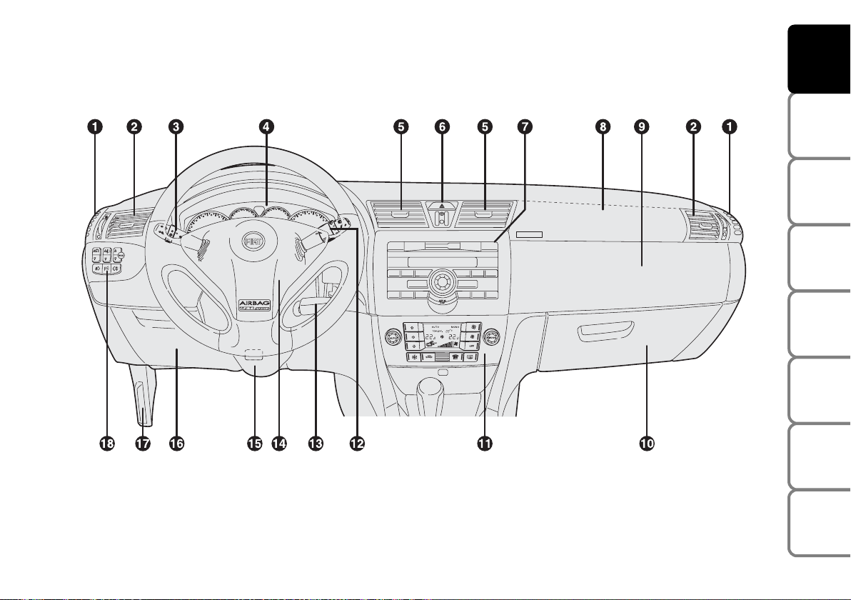
DASHBOARD
The presence and the position of the instruments and warning lights may vary according to the versions.
1. Side window air vent - 2. Adjustable and swivel air vent - 3. External light stalk - 4. Instrument panel - 5. Adjustable and swivel
air vent - 6. Hazard light switch - 7. Sound system controls - 8. Front passenger air bag - 9. Upper glovebox - 10. Lower glovebox
- 11. Controls for heating, ventilation and climate control - 12. Windscreen/rear window wiper/trip computer stalk - 13. Ignition
key and ignition switch - 14. Driver air bag - 15. Steering wheel locking/release stalk - 16. Control unit access door - 17. Bonnet
opening lever - 18. Set of switches for lights and menu opening/setting.
5
SAFETY
DEVICES
CORRECT USE
OF THE CAR
WARNING
LIGHTS AND
MESSAGES
IN AN
EMERGENCY
CAR
MAINTENANCE
TECHNICAL
SPECIFICATIONS
INDEX
DASHBOARD
AND CONTROLS
F0C0155m
fig. 1
Page 7
6
SAFETY
DEVICES
CORRECT USE
OF THE CAR
WARNING
LIGHTS AND
MESSAGES
IN AN
EMERGENCY
CAR
MAINTENANCE
TECHNICAL
SPECIFICATIONS
INDEX
DASHBOARD
AND CONTROLS
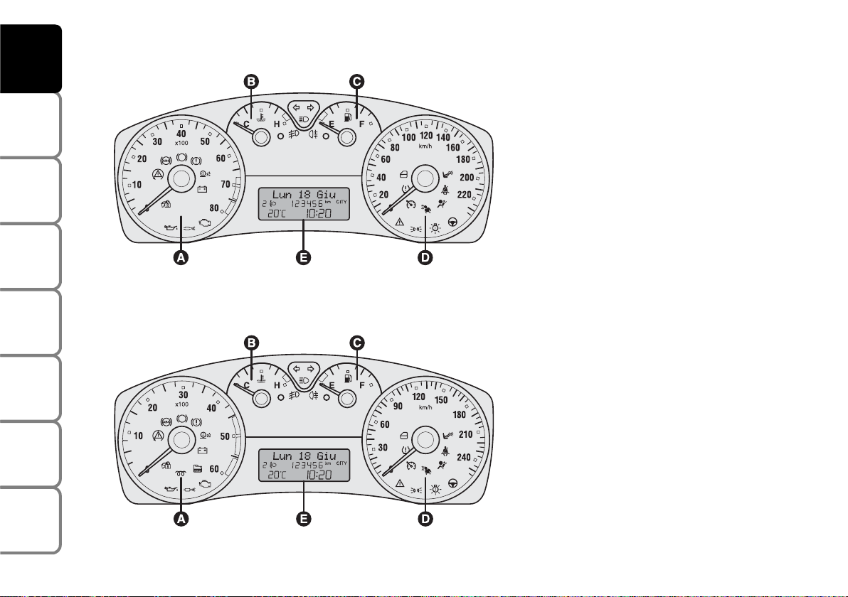
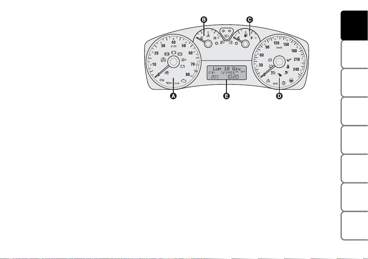
INSTRUMENT PANEL
1.416V - 1.616V - 1.816V versions
A Rev counter
B Engine coolant temperature gauge and
excessive temperature warning light
C Fuel level gauge with reserve warning
light
D Speedometer (speed indicator)
E Multifunction display.
The rev counter of versions with Selespeed transmission is fitted with warning
light t.
1.9 Multijet versions
A Rev counter
B Engine coolant temperature gauge and
excessive temperature warning light
C Fuel level gauge with reserve warning
light
D Speedometer (speed indicator)
E Multifunction display.
The rev counter of versions with Selespeed transmission is fitted with warning
light t.
F0C0521m
F0C0522m
fig. 3
fig. 2
Page 8
7
SAFETY
DEVICES
CORRECT USE
OF THE CAR
WARNING
LIGHTS AND
MESSAGES
IN AN
EMERGENCY
CAR
MAINTENANCE
TECHNICAL
SPECIFICATIONS
INDEX
DASHBOARD
AND CONTROLS
2.420V Selespeed Abarth versions
A Rev counter
B Engine coolant temperature gauge and
excessive temperature warning light
C Fuel level gauge with reserve warning
light
D Speedometer (speed indicator)
E Multifunction display.
F0C0523m
fig. 4
Page 9
8
SAFETY
DEVICES
CORRECT USE
OF THE CAR
WARNING
LIGHTS AND
MESSAGES
IN AN
EMERGENCY
CAR
MAINTENANCE
TECHNICAL
SPECIFICATIONS
INDEX
DASHBOARD
AND CONTROLS
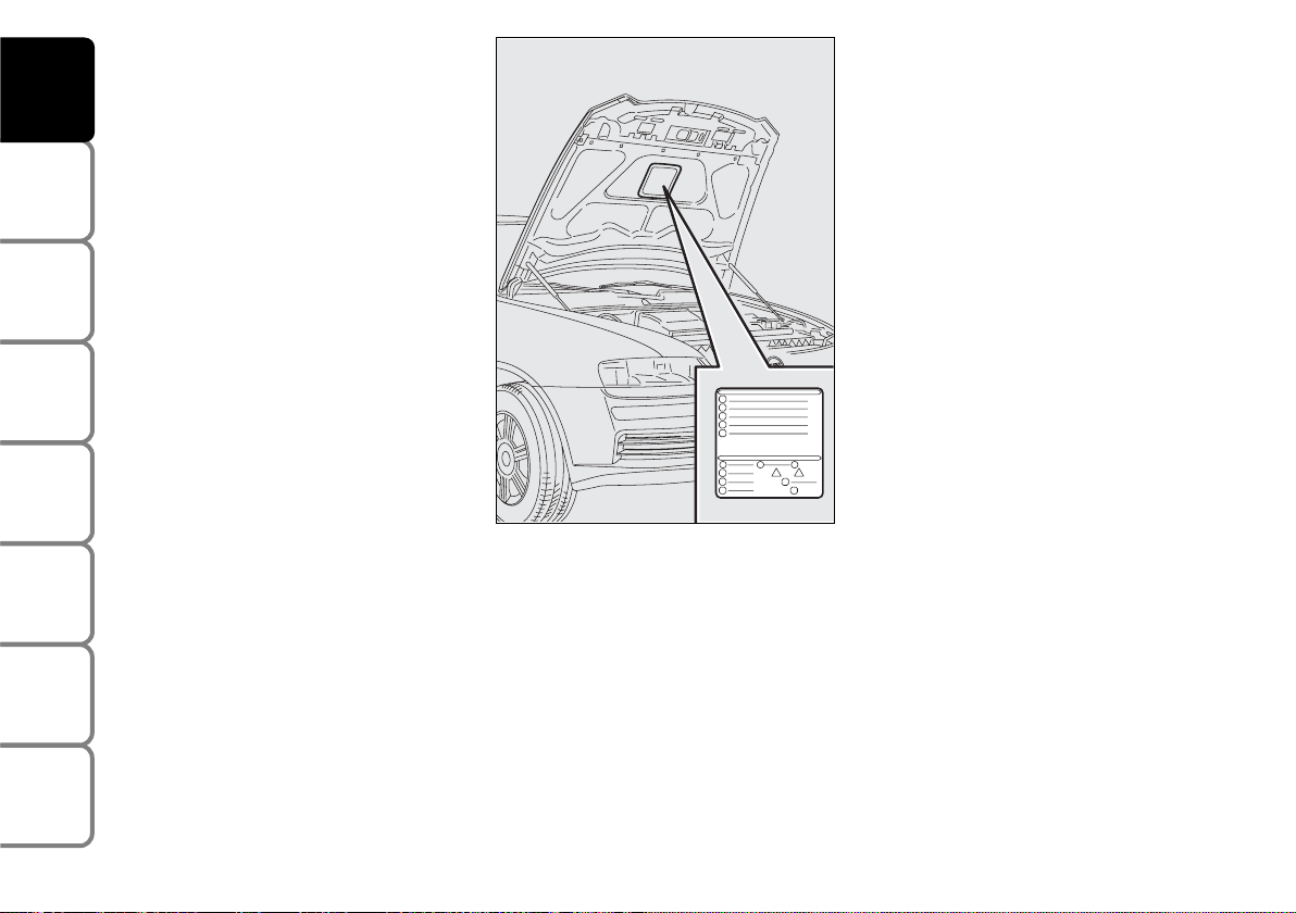
SYMBOLS
Special coloured labels have been attached
near or actually on some of the components of your car. These labels bear symbols that remind you of the precautions
to be taken as regards that particular component.
The plate summarising the symbols used
can be found under the bonnet fig. 5.
THE FIAT CODE SYSTEM
To further protect you car from theft, it
has been fitted with an engine immobilising system. This system is automatically activated when the ignition key is removed.
An electronic device, in fact, is fitted in
each ignition key grip. The device transmits a radio-frequency signal when the engine is started through a special aerial built
into the ignition switch. The modulate signal, which changes each time the engine is
started, is the “password” by means of
which the control unit recognises the key
and enables to start the engine.
fig. 5
F0C0145m
Page 10
9
SAFETY
DEVICES
CORRECT USE
OF THE CAR
WARNING
LIGHTS AND
MESSAGES
IN AN
EMERGENCY
CAR
MAINTENANCE
TECHNICAL
SPECIFICATIONS
INDEX
DASHBOARD
AND CONTROLS
OPERATION
Each time the car is started turning the ignition key to MAR, the Fiat CODE system control unit sends a recognition code
to the engine control unit to deactivate
the inhibitor.
The code is sent only if the Fiat CODE
system control unit has recognised the
code transmitted from the key.
Each time the ignition key is turned to
STOP, the Fiat CODE system deactivates
the functions of the engine electronic control unit.
If the code has not been recognised correctly, the instrument panel warning light
Y will turn on.
In this case, the key should be moved to
the STOP position and then back to
MAR; if the lock continues, possibly try
again with the other key provided with the
car. If it is still not possible to start the car
contact a Fiat Dealership.
IMPORTANT Every key has its own code,
which must be memorised by the system
control unit. To memorise new keys, up
to a maximum of eight, apply solely to Fiat Dealership taking with you the CODE
card and the keys, a personal identity document and the car’s ownership documents. The codes of the keys not provided during the new memorising procedure
are erased from the memory. This is to
ensure that any lost or stolen keys can no
longer be used to start the car.
The electronic components inside the key may be damaged
if the key is submitted to sharp
knocks.
Warning light Y coming
on when driving
❒
If the warning light Y turns on, this
means that the system is running a selftest (for example for a voltage drop).
❒
If the warning light Y continues to stay
on, contact a Fiat Dealership.
Page 11
10
SAFETY
DEVICES
CORRECT USE
OF THE CAR
WARNING
LIGHTS AND
MESSAGES
IN AN
EMERGENCY
CAR
MAINTENANCE
TECHNICAL
SPECIFICATIONS
INDEX
DASHBOARD
AND CONTROLS
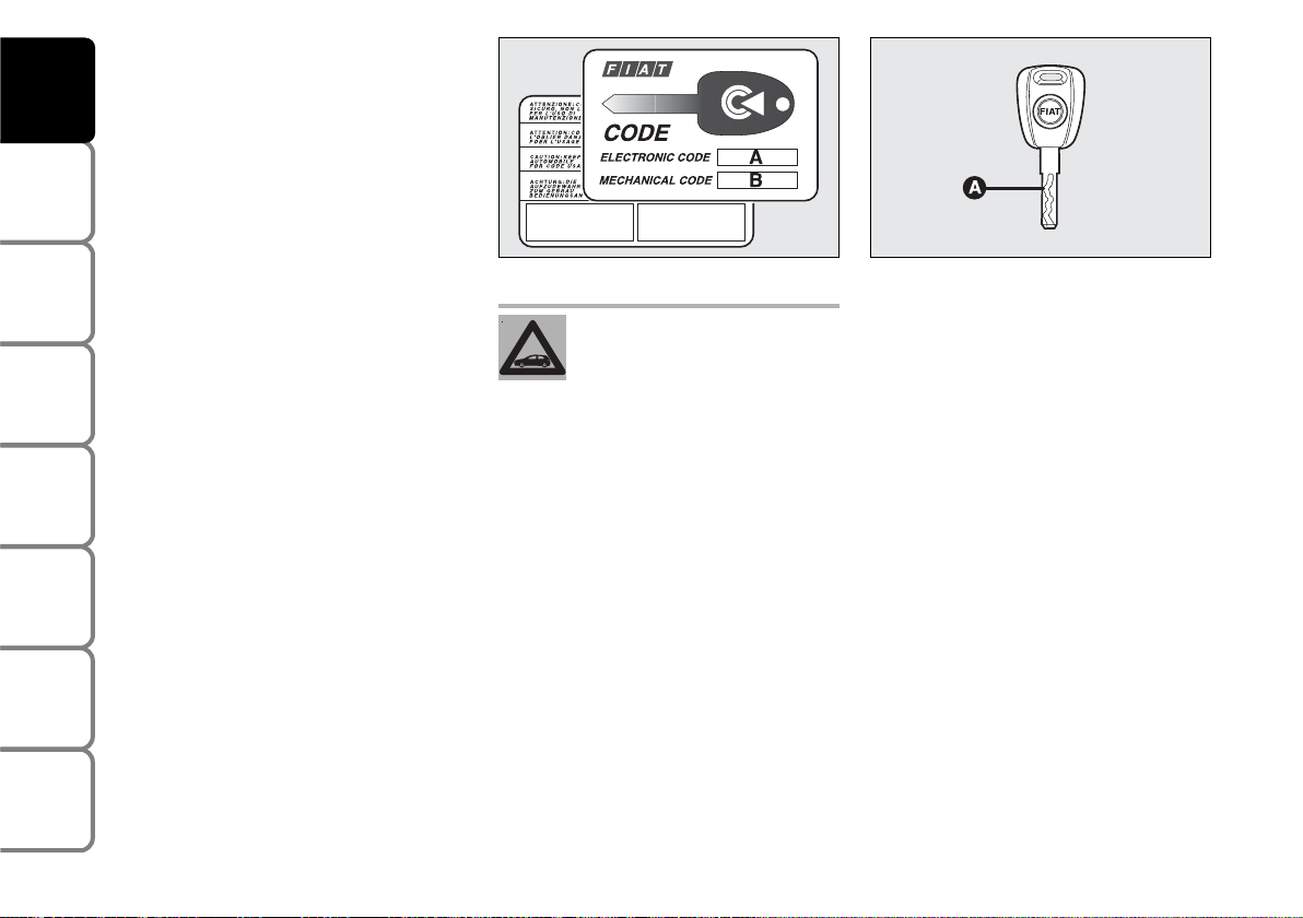
THE KEYS
CODE CARD
Together with the keys you will receive
the CODE card fig. 6 to be presented to
Fiat Dealership when requesting additional
keys.
IMPORTANT In order to ensure perfect
efficiency of the electronic devices contained inside the keys, they should never
be exposed to direct sunlight.
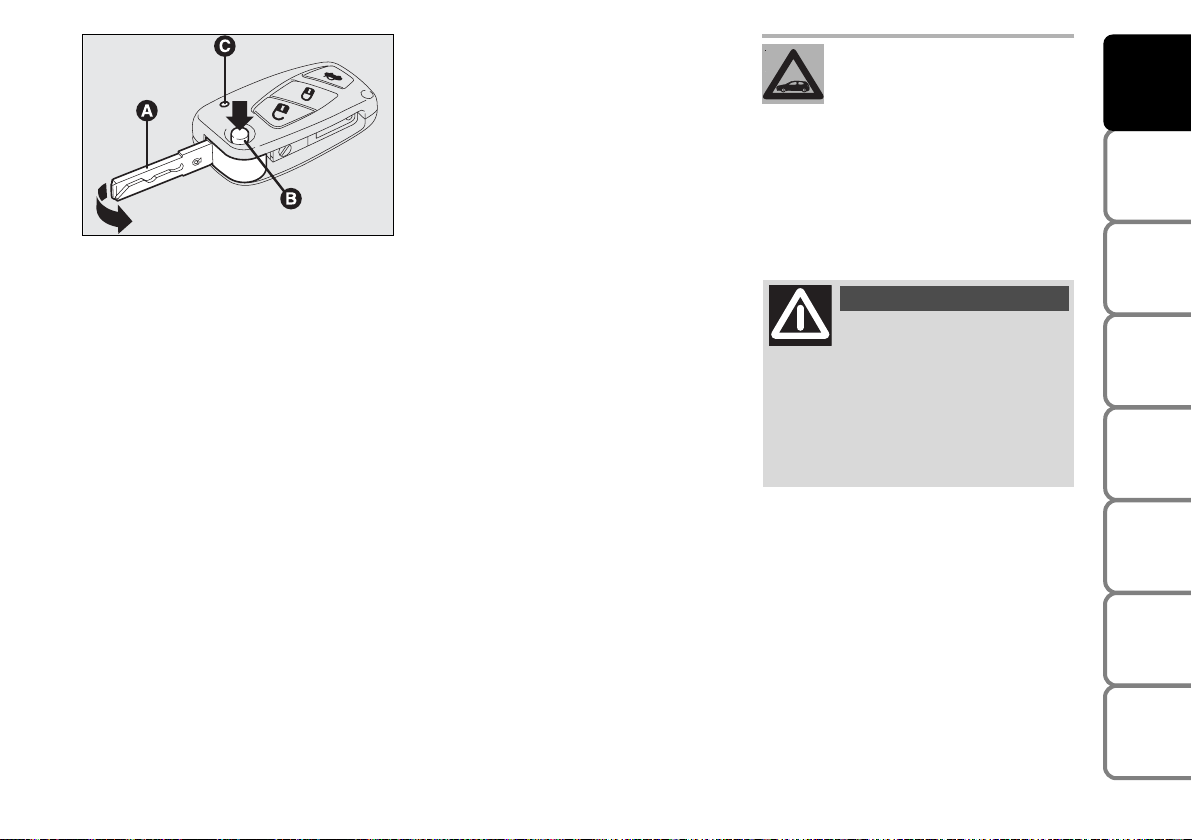
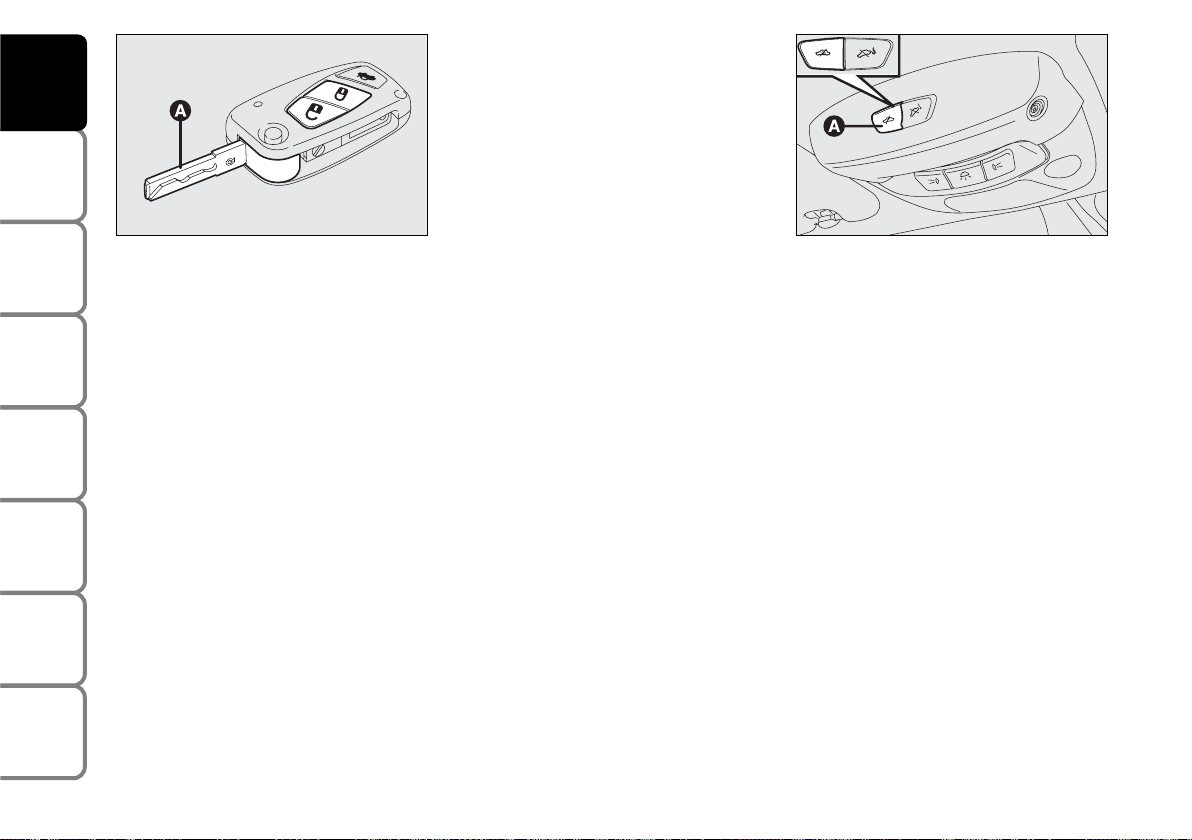
KEY WITHOUT REMOTE
CONTROL (where provided)
The key is fitted with a metal insert Afig. 7, operating:
❒
the ignition switch
❒
doors and tailgate locks
❒
the fuel lid locking/unlocking (on versions featuring fuel filler cap with lock)
❒
windows and Skywindow sunroof
(where provided) opening/closing
❒
the dead lock device (where provided)
❒
the switch to deactivate the passenger’s
air bag and rear side bags (where provided).
All the keys and the CODE
card must be handed over to
the new owner when selling
the car.
fig. 6
F0C0001m
fig. 7
F0C0508m
Page 12
11
SAFETY
DEVICES
CORRECT USE
OF THE CAR
WARNING
LIGHTS AND
MESSAGES
IN AN
EMERGENCY
CAR
MAINTENANCE
TECHNICAL
SPECIFICATIONS
INDEX
DASHBOARD
AND CONTROLS
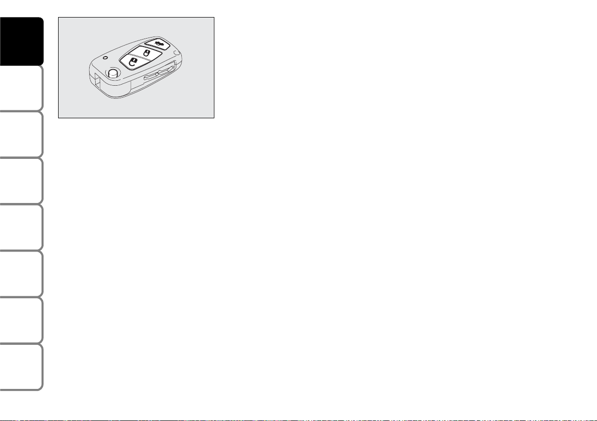
KEY WITH REMOTE CONTROL
The key is fitted with a metal insert Afig. 8, operating:
❒
the ignition switch
❒
doors and tailgate locks
❒
the fuel lid locking/unlocking (on versions featuring fuel filler cap with lock)
❒
windows and Skywindow sunroof
(where provided) opening/closing
❒
the dead lock device (where provided)
❒
the switch to deactivate the passenger’s
air bag and rear side bags (where provided).
fig. 8
F0C0327m
Button Ë for remote unlocking of doors,
tailgate and fuel filler cap. Button Áfor remote locking of doors, tailgate and fuel
filler cap. Button R for remote opening of the tailgate. Button B for power-assisted opening of the metal insert A.
To refit the metal insert into the key grip,
keep button B pressed and turn the metal insert in the direction shown by the arrow until hearing the click as it locks into
place. Then release button B. Led C
(where provided) comes on when sending the control to the alarm system receiver. To know the operating logics of
the key with remote control and every
possible and modifiable setting, see paragraph “Alarm” in this section.
If locking button
Á is inadver-
tently pressed from the pas-
senger compartment, when
getting out of the car only the doors
being used will unlock; the tailgate will
stay locked. To realign the system,
press again the locking/unlocking buttons Á / Ë.
Button B-fig. 8 should only
be pressed when the key is
away from the body, in particular
from the eyes and from objects that
can be spoilt (e.g. clothes). Make sure
the key can never be touched by others, especially children, who may inadvertently press the button.
WARNING
Page 13
12
SAFETY
DEVICES
CORRECT USE
OF THE CAR
WARNING
LIGHTS AND
MESSAGES
IN AN
EMERGENCY
CAR
MAINTENANCE
TECHNICAL
SPECIFICATIONS
INDEX
DASHBOARD
AND CONTROLS
Opening the doors and the tailgate
Briefly press button
Ë for remote un-
locking of doors and tailgate and simultaneous alarm (where provided) deactivation, timed switching on of the internal
ceiling lights and double flashing of direction indicators (for versions/markets
where applicable).
Press button Ë for more than 2 seconds
to open the windows and the Skywindow
(where provided).
For Multi Wagon versions, pressing twice
rapidly button Rwill open the rear
window lid (where provided).
Once doors are unlocked, if you do not
open one door or the tailgate within few
seconds, the system will lock all doors/tailgate again automatically.
Doors will be unlocked automatically if the
fuel inertial cut-off switch comes into operation.
Locking the doors and the tailgate
Briefly press button
Á for remote lock-
ing of doors and tailgate and simultaneous
alarm (where provided) activation, switching off of the internal ceiling lights and single flashing of direction indicators.
Press button Á for more than 2 seconds
to open the windows and the Skywindow
(where provided). If the button is briefly
pressed twice, the dead lock device is activated (see next paragraph “Dead lock
device”).
If one or more doors are open locking will
not be activated and the door led A-fig.
11 and direction indicators will flash rapidly. If only the tailgate is open the doors will
lock.
fig. 9
F0C0408m
Page 14
13
SAFETY
DEVICES
CORRECT USE
OF THE CAR
WARNING
LIGHTS AND
MESSAGES
IN AN
EMERGENCY
CAR
MAINTENANCE
TECHNICAL
SPECIFICATIONS
INDEX
DASHBOARD
AND CONTROLS
Opening the tailgate by the
remote control
Press and keep button R pressed to
open the tailgate by remote control even
if the alarm (where provided) is on.
Opening the tailgate is accompanied by the
direction indicators flashing twice; closing is accompanied by a single flash only if
the alarm is on.
If the alarm is on, when the tailgate is
opened the alarm system switches off volumetric protection and the tailgate
perimetral protection sensor.
IMPORTANT If the remote control does
not work properly, it is still possible to
carry out the above mentioned operations
by using the metal insert of the key.
When closing the tailgate again, volumetric and perimetral protection sensors are
restored.
Leds on the driver’s door
When locking the doors, led A-fig. 11
switches on for about 3 seconds and than
starts flashing (deterrence function).
Once doors are locked, if one or more
doors or the tailgate are not closed correctly, the led and direction indicators
start flashing quickly.
fig. 11
F0C0138m
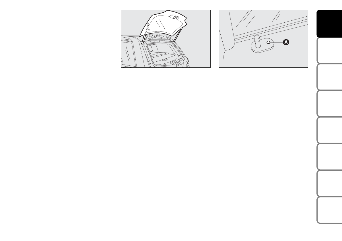
Opening the rear heated window
lid (MultiWagon versions)
On MultiWagon versions, pressing twice
button
R rapidly, obtains opening of the
rear heated window lid (see fig. 10).
fig. 10
F0C0414m
Page 15
14
SAFETY
DEVICES
CORRECT USE
OF THE CAR
WARNING
LIGHTS AND
MESSAGES
IN AN
EMERGENCY
CAR
MAINTENANCE
TECHNICAL
SPECIFICATIONS
INDEX
DASHBOARD
AND CONTROLS
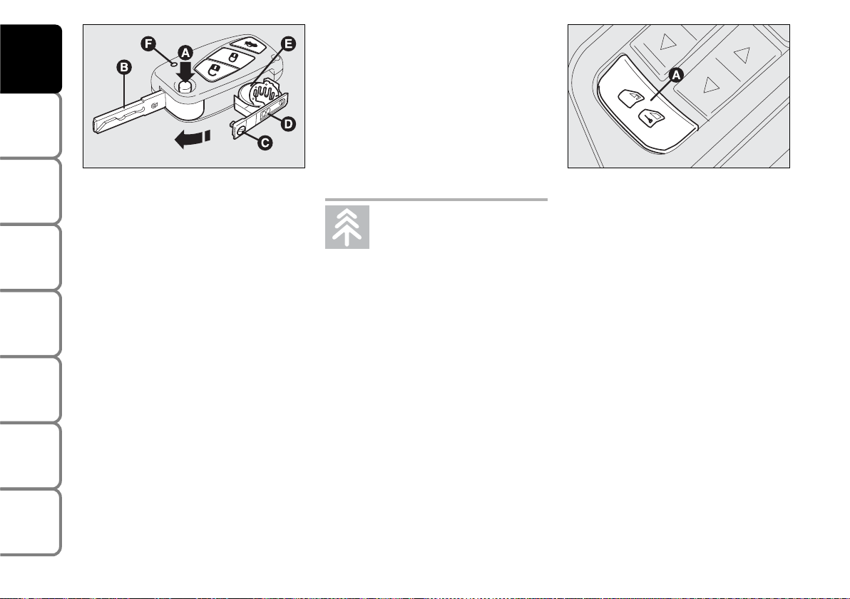
Replacing the battery of the
key with remote control
If, when pressing button Ë, Á, or R, the
led F-fig. 12 (where provided) on the key
flashes briefly only once, the battery
should be replaced with an equivalent one
that can be purchased at common stores.
Battery replacement:
❒
press button A and move the metal insert B to open position;
❒
turn the screw C to : using a fine bit
screwdriver;
❒
take out the battery case D and replace
the battery E making sure that the bias
is correct;
❒
re-insert the battery holder D in the
key and lock it turning the screw C to
;.
Request for additional remote
controls
The system can recognise up to 8 remote
controls. Should a new remote control be
necessary, contact a Fiat Dealership, taking with you the CODE card, a personal
identity document and the car’s ownership documents.
DEAD LOCK DEVICE
(where provided)
This safety device enables to inhibit:
❒
door internal handles and safety lock
button;
❒
button A-fig. 13 for locking/unlocking
the doors, placed on the driver door
panel mask;
thus hindering doors opening from inside
the passenger’s compartment in case of attempt to break-into (e.g. window breaking).
The dead lock device guarantees the best
protection against unwanted access. Therefore, it should be actuated every time the
car is parked and left unattended.
fig. 12
F0C0037m
Used batteries are harmful to
the environment. They should
be disposed of as specified by
law in the special containers
provided, or take them to a Fiat Dealership, which will deal with their disposal.
fig. 13
F0C0142m
Page 16
15
SAFETY
DEVICES
CORRECT USE
OF THE CAR
WARNING
LIGHTS AND
MESSAGES
IN AN
EMERGENCY
CAR
MAINTENANCE
TECHNICAL
SPECIFICATIONS
INDEX
DASHBOARD
AND CONTROLS
Device activation
The device is automatically activated on
every door in the following cases:
❒
turning twice the key without remote
control (where provided) in closing direction;
❒
pressing twice button Áof the key with
remote control.
Device activation is signalled by three
flashings of the direction indicators and
flashing of the led on the driver door panel (see the table on next page).
If one of the doors is not perfectly closed,
the dead lock device will not activate, thus
preventing that a person getting into the
car from the open door remains blocked
inside the passenger’s compartment when
she/he closes the door.
Device deactivation
The device is deactivated automatically on
every door in the following cases:
❒
when unlocking the doors;
❒
when unlocking only the driver’s door;
❒
when turning the ignition key to MAR.
Once the dead lock device
has been actuated, doors
cannot be opened from inside the car
in any way whatsoever. For this reason, make sure there are no persons
left inside the car.
WARNING
If the battery of the key with
remote control is down, the
dead lock device can only be activated through the metal insert of the key
in the revolving plugs of the doors as
described previously: in this case the
dead lock device is active only on the
rear doors.
WARNING
Page 17

16
SAFETY
DEVICES
CORRECT USE
OF THE CAR
WARNING
LIGHTS AND
MESSAGES
IN AN
EMERGENCY
CAR
MAINTENANCE
TECHNICAL
SPECIFICATIONS
INDEX
DASHBOARD
AND CONTROLS
The main functions that can be activated with the keys (with or without remote control) are the following:
Door opening
Key turning
counterclockwise
(driver side) or
clockwise
(passenger side)
Key turning
counterclockwise
(driver side) or
clockwise
(passenger side)
Pressing briefly
button Ë
Two flashings
Deterrence led
turning off
Door closing
Key turning
clockwise
(driver side) or
counterclockwise
(passenger side)
Key turning
clockwise
(driver side) or
counterclockwise
(passenger side)
Brief press on
button Á
1 flashing
Turned on fixed for
approx. 3 seconds
and followed by deterrence led flashing
Window and
Skywindow
opening (where
provided)
Turning (> 2
seconds) in opening
position
(counterclockwise
driver side; clockwise passenger side)
Turning (> 2
seconds) in opening
position (counterclockwise driver
side; clockwise
passenger side)
Prolonged pressing
(> 2 seconds) on
button Ë
Two flashings
Turning off
deterrence led
Window and
Skywindow
closing (where
provided)
Turning (> 2
seconds) in closing
position (clockwise
driver side;
counterclockwise
passenger side)
Turning (> 2
seconds) in closing
position (clockwise
driver side;
counterclockwise
passenger side)
Prolonged pressing
(> 2 seconds) on
button Á
1 flashing
Deterrence led
flashing
Dead lock
(where
provided)
Double key rotation
in closing direction
(clockwise driver
side; counterclockwise passenger side)
Double key rotation
in closing direction
(clockwise driver
side; counterclockwise passenger side)
Double pressing on
button Á
3 flashings
Double flashing and
then deterrent led
flashing
Tailgate
opening
Key rotation
clockwise
Key rotation
clockwise
Prolonged pressing (> 2 seconds)
on button R
Two flashings
Deterrent led
flashing
Type of
key
Key without
remote
control
(where
provided)
Key with
remote
control
Direction
indicators
flashing
(only with
key with
remote
control)
Led on
driver door
Page 18

17
SAFETY
DEVICES
CORRECT USE
OF THE CAR
WARNING
LIGHTS AND
MESSAGES
IN AN
EMERGENCY
CAR
MAINTENANCE
TECHNICAL
SPECIFICATIONS
INDEX
DASHBOARD
AND CONTROLS
ALARM
(where provided)
The alarm function is provided in addition
to all remote control functions previously described and it is controlled by the receiver located under the dashboard, next
to the fuse box.
WHEN THE ALARM IS
TRIGGERED
The alarm comes into action in the following cases:
❒
unlawful opening of one of the doors,
bonnet or boot (perimetral protection);
❒
attempt to start the engine (turning the
ignition key to MAR);
❒
battery cable cutting;
❒
presence of moving bodies in the passenger’s compartment (volumetric protection);
❒
abnormal raising/sloping of the car.
Depending on the markets, the cutting in
of the alarm causes operation of the siren
and direction indicators (for about 26 seconds). The ways of operating and the number of cycles may vary depending on the
markets.
A maximum number of sound/sight cycles
is however envisaged.
Volumetric and anti-raising protections
can be cut off by operating the front ceiling light controls (see paragraphs “Volumetric protection sensors” and “Anti-raising sensor” on the following pages).
IMPORTANT The engine immobiliser
function is guaranteed by the Fiat CODE
system, which is automatically activated
when the ignition key is removed.
HOW TO ACTIVATE THE
ALARM
With the doors, bonnet and boot shut and
the ignition key in the STOP position or
with the key removed, point the key with
remote control in the direction of the car,
then press and release the button
Á.
With the exception of certain markets,
the system sounds a “beep” and the doors
are locked.
Engagement of the alarm is preceded by
a self-diagnostic test. If a fault is detected
the system sounds a further warning
“beep” and the display shows the relevant
message (see section “Warning lights and
messages”).
In this case, switch the alarm system off by
pressing button
Ë, check that the doors,
bonnet and tailgate are properly shut, then
switch the alarm on again by pressing but-
ton Á.
Otherwise, the door, bonnet or tailgate
that is not shut properly will be excluded
from the alarm system control.
Page 19
18
SAFETY
DEVICES
CORRECT USE
OF THE CAR
WARNING
LIGHTS AND
MESSAGES
IN AN
EMERGENCY
CAR
MAINTENANCE
TECHNICAL
SPECIFICATIONS
INDEX
DASHBOARD
AND CONTROLS
If the doors, bonnet and boot are shut
correctly and the control signal is repeated, the system self-diagnostics has detected a system operating fault. It is therefore necessary to contact Fiat Dealership.
IMPORTANT When operating the central door locking with the metal insert A-
fig. 14 of the key, the alarm is not activated.
IMPORTANT The electronic alarm is built
in compliance with the law and regulations
of the different countries.
HOW TO DEACTIVATE
THE ALARM
Press button
Ë of the key with remote
control.
The system will react as follows (with the
exception of certain markets):
❒
two brief flashes of the direction indicators;
❒
two brief “beeps”;
❒
door unlocking.
IMPORTANT Operating the central door
locking with the metal insert of the key
will not deactivate the alarm.
VOLUMETRIC PROTECTION
SENSORS
The volumetric sensors are inside the
front ceiling light in the passenger’s compartment. To make sure that the volumetric sensors are working properly,
check that doors, boot, bonnet, windows
and Skywindow (where provided) are
shut.
Volumetric protection
deactivation
If it is necessary to switch on the alarm
when animals or people are in the car,
press button A-fig. 15 on the front ceiling light to deactivate the volumetric protection.
Deactivation is needed also in the presence of additional independent heater and
when it is switched on with the remote
control.
Protection cut-out stays on until activating the central door opening again.
fig. 14
F0C0335m
fig. 15
F0C0286m
Page 20
19
SAFETY
DEVICES
CORRECT USE
OF THE CAR
WARNING
LIGHTS AND
MESSAGES
IN AN
EMERGENCY
CAR
MAINTENANCE
TECHNICAL
SPECIFICATIONS
INDEX
DASHBOARD
AND CONTROLS
ANTI-RAISING SENSOR
The anti-raising sensor detects any abnormal car raising/sloping, even partial
(e.g.: attempt to remove a wheel).
This sensor can detect the smallest car
sideslip angle changes, both longitudinally
and transversally.
Sideslip angle changes lower than 0.5°/min.
(e.g.: slow tyre flattening) are not considered.
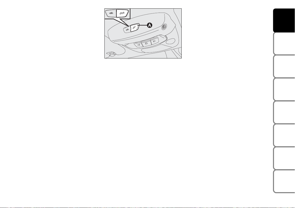
Anti-raising protection
deactivation
To deactivate the anti-raising protection
(for example when towing the car with
alarm on) press button A-fig. 16 on the
front ceiling light. Sensor cut-out stays on
until activating the central door opening
again.
INDICATIONS OF ATTEMPTS
TO BREAK IN
Any attempt to break in is indicated by
warning light
Y on the instrument pan-
el with the relevant message on the display (see section “Warning lights and messages”).
HOW TO CUT OFF THE ALARM
SYSTEM
To deactivate the alarm system completely (for instance during prolonged inactivity of the car) simply lock the car
turning the metal insert of the key with remote control in the lock.
IMPORTANT To cut-out the electronic
alarm if remote control batteries are
down or the system is failing, fit the key
into the ignition switch and turn it to
MAR.
fig. 16
F0C0287m
Page 21
20
SAFETY
DEVICES
CORRECT USE
OF THE CAR
WARNING
LIGHTS AND
MESSAGES
IN AN
EMERGENCY
CAR
MAINTENANCE
TECHNICAL
SPECIFICATIONS
INDEX
DASHBOARD
AND CONTROLS
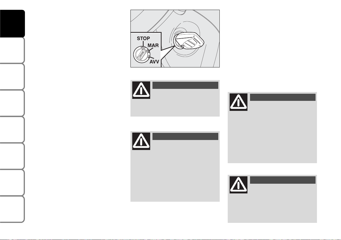
IGNITION SWITCH
The key can be turned to 3 different positions:
❒
STOP: engine off, key can be removed,
steering column locked. Certain electrical devices (e.g.: sound system, central door locking, electronic alarm, etc.)
can work.
❒
MAR: driving position. All electrical devices are powered.
❒
AVV: engine starting.
The ignition switch is fitted with a safety
mechanism that, in the event the engine is
not started, compels the driver to turn the
ignition key back to STOP before repeating the starting operation.
STEERING COLUMN LOCK
Engaging
When the key is at STOP remove the
key and turn the steering wheel until it
locks.
Disengaging
Rock the steering wheel slightly as you
turn the ignition key to MAR.
fig. 17
F0C0164m
If the ignition device is tam-
pered with (e.g.: attempted
theft), have it checked over by a Fiat
Dealership before restarting to drive.
WARNING
When getting out of the car,
always remove the key to
prevent any occupants from accidentally activating the controls. Remember to engage the handbrake
and if the car is parked on uphill slope
to engage the first gear. If the car is
facing downhill, engage the reverse
gear. Never leave unsupervised children in the car.
WARNING
It is absolutely forbidden to
carry out whatever aftermarket operation involving steering
system or steering column modifications (e.g.: installation of anti-theft
device) that could badly affect performance and safety, cause the lapse
of warranty and also result in noncompliance of the car with homologation requirements.
WARNING
Never remove the ignition
key while the car is moving.
The steering wheel would automatically lock as soon as you try to turn
it. This also applies when the car is
being towed.
WARNING
Page 22

21
SAFETY
DEVICES
CORRECT USE
OF THE CAR
WARNING
LIGHTS AND
MESSAGES
IN AN
EMERGENCY
CAR
MAINTENANCE
TECHNICAL
SPECIFICATIONS
INDEX
DASHBOARD
AND CONTROLS
INSTRUMENTS
REV. COUNTER fig. 18a
The rev counter shows engine rpm. The
needle pointed to the red area (danger)
indicates excessive high engine speed. Do
not drive for long periods with the needle
in this area.
IMPORTANT The electronic injection control system gradually shuts off the flow of
fuel when the engine is “over-revving” resulting in a gradual loss of engine power.
When the engine is idling, the rev counter
may indicate a gradual or sudden speed increase. This is normal as it takes place during normal operation, for example when
activating the climate control system or
the fan. In particular a slow change in the
speed preserves the battery charge.
fig. 18a
F0C0527m
fig. 18
F0C0530m
SPEEDOMETER fig. 18
It shows the car speed.
Page 23
22
SAFETY
DEVICES
CORRECT USE
OF THE CAR
WARNING
LIGHTS AND
MESSAGES
IN AN
EMERGENCY
CAR
MAINTENANCE
TECHNICAL
SPECIFICATIONS
INDEX
DASHBOARD
AND CONTROLS
If the needle reaches the red
area, stop the engine immediately and contact a Fiat Dealership.
fig. 19
F0C0528m
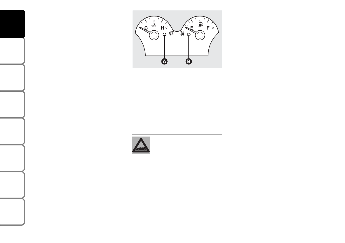
ENGINE COOLANT
TEMPERATURE GAUGE
This shows the temperature of the engine
coolant fluid and begins working when the
fluid temperature exceeds approx. 50°C.
Under normal conditions, the needle
should move to different positions of the
scale according to the conditions of use of
the car.
C - Low engine coolant temperature.
H - High engine coolant temperature.
FUEL LEVEL GAUGE
This shows the amount of fuel left in the
fuel tank.
The reserve warning light B- fig. 19 turns
on to indicate that approx. 8 litres of fuel
are left in the tank.
E - tank empty.
F - tank full (see the indications given in
paragraph “At the filling station").
Do not travel with the fuel tank almost
empty: the gaps in fuel delivery could damage the catalyst.
IMPORTANT If the needle sets at E with
warning light B flashing, it means that the
system is malfunctioning. Contact a Fiat
Dealership to have the system inspected.
The turning on of the warning light A-fig.
19 (together with the message shown on
the display) indicates that the coolant fluid temperature is too high; in this case,
stop the engine and contact a Fiat Dealership.
Page 24
23
SAFETY
DEVICES
CORRECT USE
OF THE CAR
WARNING
LIGHTS AND
MESSAGES
IN AN
EMERGENCY
CAR
MAINTENANCE
TECHNICAL
SPECIFICATIONS
INDEX
DASHBOARD
AND CONTROLS
MULTIFUNCTION
DISPLAY
Your car is fitted with the multifunction
display that shows all the useful information necessary when driving.
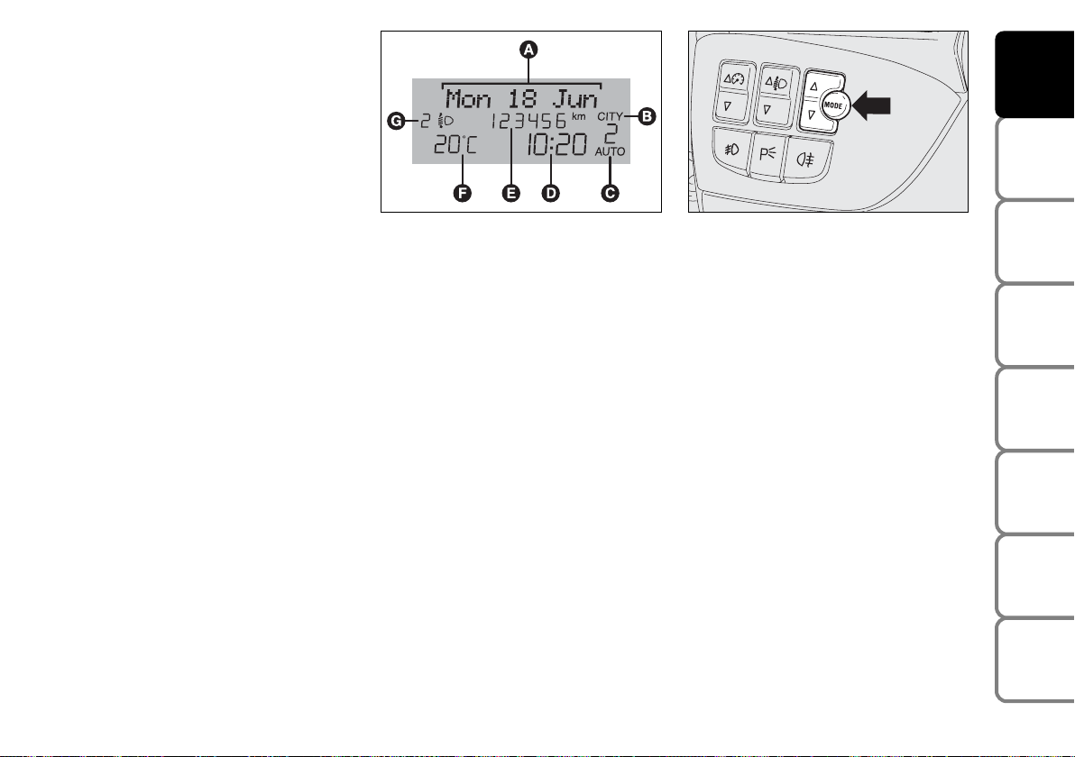
INFORMATION ON
“STANDARD” SCREEN fig. 20
The standard screen shows the following
indications:
A Date
B Dualdrive electric power steering en-
gagement, if any
C Selespeed mode (where provided) and
engaged gear display
D Clock
E Odometer (covered km or miles)
F External temperature
G Headlight aiming position (only with
dipped beam headlights on)
CONTROL BUTTONS fig. 21
Õ To scroll the display and the related
options upwards or to increase the
value displayed.
MODE Brief press to open the menu
and/or to move to next screen or to confirm the option required.
Long press to go back to the standard
screen.
Ô To scroll the display and the related op-
tions downwards or to decrease the
value displayed.
Note Buttons
Õ and Ô activate different
functions according to the following situations:
– to scroll the menu options upwards and
downwards;
– to increase or to decrease values during
settings.
fig. 21
F0C0022m
fig. 20
F0C3245g
Page 25

24
SAFETY
DEVICES
CORRECT USE
OF THE CAR
WARNING
LIGHTS AND
MESSAGES
IN AN
EMERGENCY
CAR
MAINTENANCE
TECHNICAL
SPECIFICATIONS
INDEX
DASHBOARD
AND CONTROLS
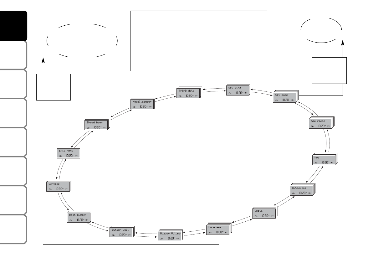
SETUP MENU fig. 22
The menu comprises a series of functions
arranged in a “circular fashion” which can
be selected through buttons Õ and Ô to
access the different select operations and
settings (setup) given below. For certain
options (Set time and Units) there is a submenu.
The setup menu can be activated by pressing briefly button MODE.
Single presses on buttons
Õ or Ô will
scroll the setup menu options. Handling
modes differ with each other according to
the characteristic of the option selected.
Note If the car is equipped with Connect/Navigator, phone and audio info can
be repeated on the multifunction display.
For other set-up menu adjustments and/or
settings, see the Connect/Navigator Supplement.
Selecting an option in the main menu
without submenu:
– press briefly button MODE to select
the menu option to set;
– press buttons Õ or Ô (by single presses) to select the new setting;
– press briefly button MODE to store the
new setting and to go back to the previously selected menu option.
Selecting an option in the main menu with
submenu:
– press briefly button MODE to display
the first submenu option;
– press buttons
Õ or Ô (by single press-
es) to scroll all submenu options;
– press briefly button MODE to select
the displayed submenu option and to enter the relevant setup menu;
– press buttons
Õ or Ô (by single press-
es) to select the new setting;
– press briefly button MODE to store the
new setting and to go back to the previously selected submenu option.
Page 26

25
SAFETY
DEVICES
CORRECT USE
OF THE CAR
WARNING
LIGHTS AND
MESSAGES
IN AN
EMERGENCY
CAR
MAINTENANCE
TECHNICAL
SPECIFICATIONS
INDEX
DASHBOARD
AND CONTROLS
Selecting “Set date” and “Set time”:
– briefly press button MODE to select
the first value to change (e.g. hours /minutes or year / month / day);
– press buttons Õ or Ô (by single presses) to select the new setting;
– briefly press button MODE to store the
new setting and to go to the next setup
menu option, if this is the last one you will
go back to the previously selected option
of the main menu.
Press button MODE for long:
– to quit the submenu if you are at submenu option setting level;
– to quit the main menu if you are at submenu level;
– to quit the main menu if you are at main
menu option setting level;
– to quit the set up menu if you are in the
main menu;
– only settings stored yet by the user (and
confirmed by pressing briefly button
MODE) will be saved.
The setup menu displaying is timed; when
quitting the menu due to timing expiry,
only settings stored yet by the user (and
confirmed by pressing briefly button
MODE) will be saved.
Page 27
26
SAFETY
DEVICES
CORRECT USE
OF THE CAR
WARNING
LIGHTS AND
MESSAGES
IN AN
EMERGENCY
CAR
MAINTENANCE
TECHNICAL
SPECIFICATIONS
INDEX
DASHBOARD
AND CONTROLS
Day
Year
Month
Español
English
Portuges
Deutsch
Français
Italiano
EXIT MENU
TRIP B DATA
SET TIME
SET DATE
SEE RADIO
KEY
AUTOCLOSE
UNITS
LANGUAGE
BUZZER VOLUME
BUTTON VOL.
BELT BUZZER
SERVICE
SPEED BEEP
Briefly press button MODE to start surfing from the standard
screen. To surf the menu use buttons Õ or Ô. For safety reasons, when the car is running, it is possible to access only the
reduced menu (for setting the “Speed limit” and “Automatic
headlight sensor sensitivity adjustment” (where provided).
When the car is stationary access to the whole menu is enabled. On cars provided with Connect/Navigator many functions are displayed on the navigator display.
MODE
briefly press
button
MODE
briefly press
button
Example:
fig. 22
HEADL. SENSOR
F0C2369g
Page 28

27
SAFETY
DEVICES
CORRECT USE
OF THE CAR
WARNING
LIGHTS AND
MESSAGES
IN AN
EMERGENCY
CAR
MAINTENANCE
TECHNICAL
SPECIFICATIONS
INDEX
DASHBOARD
AND CONTROLS
Speed limit (Speed Beep)
With this function it is possible to set the
car speed limit (km/h or mph); when this
limit is exceeded the driver is immediately alerted (see section “Warning lights and
messages”).
To set the speed limit, proceed as follows:
– briefly press button MODE, the display
will show wording (Speed Beep);
– press button
Õ or Ô to select activa-
tion (On) or deactivation (Off) of the
speed limit;
– if selecting (On), press button Õ or Ô
to select the required speed limit and then
press MODE to confirm.
Note The possible setting is between 30
and 250 km/h, or between 20 and 155
mph depending on the unit set previously (see paragraph “Distance unit (Distances)” described later. Every press on
button
Õ/Ô increases/decreases by 5
units. Keeping the button Õ/Ô pressed
obtains the automatic fast increase or decrease. When you are near the required
setting complete adjustment by single
presses.
– briefly press button MODE to go back
to the menu screen or press the button
for long to go back to the standard screen
without storing settings.
To abort the setting, proceed as follows:
– briefly press button MODE: (On) will
flash on the display;
– press button Ô: (Off) will flash on the
display;
– briefly press button MODE to go back
to the menu screen or press the button
for long to go back to the standard screen
without storing settings.
Automatic headlight sensor
sensitivity adjustment
(Headl. sensor) (where provided)
With this function it is possible to adjust
the light sensor sensitivity according to 3
levels (level 1 = min. level, level 2 = average level, level 3 = max. level); the higher the sensitivity is, the lower is the external light intensity required to switch on
the lights.
This operation can be performed also with
the car moving.
To set the light level required, proceed as
follows:
– briefly press button MODE, the previously set level will flash on the display;
– press button
Õ or Ô to select the re-
quired level;
– briefly press button MODE to go back
to the menu screen or press the button
for long to go back to the standard screen
without storing settings.
Page 29

28
SAFETY
DEVICES
CORRECT USE
OF THE CAR
WARNING
LIGHTS AND
MESSAGES
IN AN
EMERGENCY
CAR
MAINTENANCE
TECHNICAL
SPECIFICATIONS
INDEX
DASHBOARD
AND CONTROLS
Trip B On/Off (TripB data)
Through this option it is possible to activate (On) or deactivate (Off) the Trip B
(partial trip) (for further information see
“Trip computer”).
For activation / deactivation, proceed as
follows:
– briefly press button MODE: (On) or
(Off) will flash on the display (according to
previous setting);
– press button
Õ or Ô for setting;
– briefly press button MODE to go back
to the menu screen or press the button
for long to go back to the standard screen
without storing settings.
Setting the clock (Set time)
This function enables to set the clock
through two submenus: “Time” and
“Mode”.
To set the clock proceed as follows:
– briefly press button MODE, the display
will show the two submenus “Time” and
“Mode”;
– press button
Õ or Ô to scroll the two
submenus;
– select the required submenu and then
press briefly MODE;
– if selecting “Time”: briefly press button
MODE, “hours” will flash on the display;
– press button
Õ or Ô for setting;
– press button MODE, “minutes” will
flash on the display;
– press button
Õ or Ô for setting.
– if selecting “Mode”: briefly press button MODE, “12h” or “24h” will flash on
the display;
– press button Õ or Ô to select “24h” or
“12h”.
After setting, briefly press button MODE
to go back to the submenu screen or
press the button for long to go back to the
main menu screen without storing settings.
– press again button MODE for long to
go back to the standard screen or to the
main menu according to the current menu
level.
Page 30

29
SAFETY
DEVICES
CORRECT USE
OF THE CAR
WARNING
LIGHTS AND
MESSAGES
IN AN
EMERGENCY
CAR
MAINTENANCE
TECHNICAL
SPECIFICATIONS
INDEX
DASHBOARD
AND CONTROLS
Setting the date (Set date)
This function enables to update the date
(day – month – year).
To correct the date proceed as follows:
– briefly press button MODE: “year” will
flash on the display;
– press button
Õ or Ô for setting;
– briefly press button MODE: “month”
will flash on the display;
– press button
Õ or Ô for setting;
– briefly press button MODE: “day” will
flash on the display;
– press button Õ or Ô for setting.
Note Every press on button
Õ or Ô in-
creases/decreases by 1 unit. Keeping the
button pressed obtains automatic fast increase or decrease. When you are near
the required setting complete adjustment
by single presses.
– briefly press button MODE to go back
to the menu screen or press the button
for long to go back to the standard screen
without storing settings.
Audio info repetition (See radio)
With this function the display repeats information relevant to the sound system.
– Radio: selected radio station frequency
or RDS message;
– Audio CD/MP3 CD: CD and/or track
number;
To activate (On) or to deactivate (Off)
sound system info displaying proceed as
follows:
– briefly press button MODE: (On) or
(Off) will flash on the display (according to
previous setting);
– press button
Õ or Ô for setting;
– briefly press button MODE to go back
to the menu screen or press the button
for long to go back to the standard screen
without storing settings.
Door opening mode (Key)
This function enables to select the required door opening mode:
– briefly press button MODE, the display
will show the wording “Key”;
– press button
Õ or Ô to select option
“Open doors” or “Open all”;
– briefly press button MODE to go back
to the menu screen or press the button
for long to go back to the standard screen
without storing settings.
– “Open doors”: press button Ë to open
the doors (excluding the tailgate);
– “Open all”: press button
Ë to open the
doors and the tailgate.
Page 31

30
SAFETY
DEVICES
CORRECT USE
OF THE CAR
WARNING
LIGHTS AND
MESSAGES
IN AN
EMERGENCY
CAR
MAINTENANCE
TECHNICAL
SPECIFICATIONS
INDEX
DASHBOARD
AND CONTROLS
Automatic central door locking
when travelling (Autoclose)
When activated (On), this function locks
automatically the doors when the car
speed exceeds 20 km/h.
To activate (On) or to deactivate (Off) this
function proceed as follows:
– briefly press button MODE, the display
will show the wording “Travelling”. Wordings On or Off will flash (according to previous setting);
– press button
Õ or Ô for setting;
– briefly press button MODE to go back
to the menu screen or press the button
for long to go back to the standard screen
without storing settings.
Setting units (Units)
With this function it is possible to set the
units through three submenus: “Distances”, “Consumption” and “Temperature”.
To set the required unit proceed as follows:
– briefly press button MODE, the display
will show the three submenus;
– press button
Õ or Ô to scroll the three
submenus;
– select the required submenu and then
press briefly button MODE;
– if selecting “Distances”: pressing button
MODE briefly, the display will show “km”
or “mi” (according to previous setting);
– press button
Õ or Ô for setting;
– if selecting “Consumption”: pressing button MODE briefly, the display will show
“km/l ”, “l/100km” or “mpg” (according to
previous setting);
If set unit is “km”, the display will show fuel consumption in km/l or l/100km.
If set unit is “mi” the display will show fuel consumption in “mpg”.
– press button Õ or Ô for setting;
– if selecting “Temperature”: pressing button MODE briefly, the display will show
“°C” or “°F” (according to previous setting);
– press button
Õ or Ô to select the re-
quired level;
Page 32

31
SAFETY
DEVICES
CORRECT USE
OF THE CAR
WARNING
LIGHTS AND
MESSAGES
IN AN
EMERGENCY
CAR
MAINTENANCE
TECHNICAL
SPECIFICATIONS
INDEX
DASHBOARD
AND CONTROLS
After setting, briefly press button MODE
to go back to the submenu screen or
press the button for long to go back to the
main menu screen without storing settings.
– press again button MODE for long to
go back to the standard screen or to the
main menu according to the current menu
level.
Selecting the language (Language)
Display messages can be shown in different languages: Italian, French, Spanish, Portuguese, German, English.
To set the required language proceed as
follows:
– briefly press button MODE: the previously set “language” will flash on the display;
– press button
Õ or Ô for setting;
– briefly press button MODE to go back
to the menu screen or press the button
for long to go back to the standard screen
without storing settings.
Setting the buzzer volume
(Buzzer volume)
With this function the volume of the
buzzer accompanying any failure/warning
indication can be adjusted according to 8
levels.
To set the required the volume proceed
as follows:
– briefly press button MODE: the previously set volume “level” will flash on the
display;
– press button
Õ or Ô for setting;
– briefly press button MODE to go back
to the menu screen or press the button
for long to go back to the standard screen
without storing settings.
Page 33

32
SAFETY
DEVICES
CORRECT USE
OF THE CAR
WARNING
LIGHTS AND
MESSAGES
IN AN
EMERGENCY
CAR
MAINTENANCE
TECHNICAL
SPECIFICATIONS
INDEX
DASHBOARD
AND CONTROLS
Adjusting the button volume
(Button vol.)
With this function the volume of the
roger-beep accompanying the activation
of buttons MODE, Õ and Ô can be adjusted according to 8 levels.
To set the required the volume proceed
as follows:
– briefly press button MODE: the previously set volume “level” will flash on the
display;
– press button
Õ or Ô for setting;
– briefly press button MODE to go back
to the menu screen or press the button
for long to go back to the standard screen
without storing settings.
S.B.R. buzzer reactivation
(Belt buzzer)
This function can be only displayed after
Fiat Dealership has deactivated the S.B.R.
system (see paragraph “S.B.R. system” in
section “Safety devices”).
Scheduled Servicing (Service)
Through this function it is possible to display information connected to proper car
servicing.
To display scheduled servicing info proceed as follows:
– briefly press button MODE: service in
km or mi, according to previous setting,
will be displayed (see paragraph “Distance
unit”);
– press button
Õ or Ô to select display-
ing in days;
– briefly press button MODE to go back
to the menu screen or press the button
for long to go back to the standard screen
without storing settings.
Page 34

33
SAFETY
DEVICES
CORRECT USE
OF THE CAR
WARNING
LIGHTS AND
MESSAGES
IN AN
EMERGENCY
CAR
MAINTENANCE
TECHNICAL
SPECIFICATIONS
INDEX
DASHBOARD
AND CONTROLS
Note The “Service Schedule” includes car
maintenance every 30,000 km (or equivalent value in miles) or every year; this is
shown automatically, with the ignition key
at MAR, starting from 2,000 km (or equivalent value in miles) or 30 days from this
deadline and it is shown again every 200
km (or equivalent value in miles) or every
3 days. Below 200 km servicing indications
are displayed more frequently. Servicing
indication will be displayed in km or mi according to previous setting. When a programmed maintenance interval (coupon)
is near to come, turning the ignition key
to MAR, the display will show the message “Service” followed by the number of
km/mi or days to go before car servicing.
“Scheduled servicing” message is displayed
in km/mi or days according to the approaching service interval. Contact a Fiat
Dealership to carry out any service operation provided by the “Service schedule” or “Annual inspection plan”, and to
reset the display.
Exit Menu
This is the last function that closes the circular setting cycle listed in the initial menu
screen.
Briefly press button MODE to go back to
the standard screen without storing settings.
Press button
Ô to return to the first menu
option (Speed Beep).
Instrument panel, display and
button lighting adjustment
(Light rheostat)
With this function it is possible to adjust
the lighting (dimming/brightening) of the
instrument panel, sound system display,
Connect/Navigator display, two-zone climate control display and steering wheel
controls.
Press buttons Õ/Ô fig. 23 for light adjustment to carry out required light adjustment.
Return to standard screen is automatic or
by pressing briefly button MODE.
fig. 23
F0C0259m
Page 35

34
SAFETY
DEVICES
CORRECT USE
OF THE CAR
WARNING
LIGHTS AND
MESSAGES
IN AN
EMERGENCY
CAR
MAINTENANCE
TECHNICAL
SPECIFICATIONS
INDEX
DASHBOARD
AND CONTROLS
TRIP COMPUTER
GENERAL
The “Trip computer” displays information
(with ignition key at MAR), relating to the
operating status of the car.
This function comprises the “General trip”
concerning the “complete mission” of the
car (journey) and “Trip B”, concerning the
partial mission of the car; this latter function is “contained” (as shown in fig. 25)
within the complete mission. Both functions are resettable (reset - start of new
mission).
“General Trip” displays the figures relating to:
– Range
– Trip distance
– Average consumption
– Instant consumption
– Average speed
– Trip time (driving time).
“Trip B” displays the figures relating to:
– Trip distance B
– Average consumption B
– Average speed B
– Trip time B (driving time).
Note “Trip B” function can be excluded
(see paragraph “Trip B On/Off”). “Range”
and “Instant consumption” cannot be reset.
Values displayed
Range
This value shows the distance in km (or
mi) that the car can still cover before
needing fuel, assuming that driving conditions are kept unvaried. The display will
show “----” if the range value is below 50
km (or 30 mi).
Trip distance
This value shows the distance covered
from the start of the new mission.
Average consumption
This value shows the average consumption from the start of the new mission.
Instant consumption
This value shows instant fuel consumption
(this value is updated second by second). If
parking the car with engine on, the display
will show “----”.
Average speed
This value shows the car average speed as
a function of the overall time elapsed since
the start of the new mission.
Page 36

35
SAFETY
DEVICES
CORRECT USE
OF THE CAR
WARNING
LIGHTS AND
MESSAGES
IN AN
EMERGENCY
CAR
MAINTENANCE
TECHNICAL
SPECIFICATIONS
INDEX
DASHBOARD
AND CONTROLS
fig. 24
F0C0023m
Trip time
This value shows the time elapsed since
the start of the new mission.
IMPORTANT Lacking information, Trip
computer values are displayed with “----”.
When normal operating condition is reset, calculation of different units will
restart regularly. Values displayed before
the failure will not be reset.
TRIP button fig. 24
The TRIP button, set on right steering column stalk, shall be used (with ignition key
at MAR), to display and to reset the previously described values to start a new
mission:
– short push to display the different values;
– long push to reset and then start a new
mission.
New mission
New mission starts after:
– “manual” resetting by the user, by pressing the relevant button;
– “automatic” resetting, when the “trip
distance” reaches 4999,9 km or when the
“trip time” reaches 99.59 (99 hours and
59 minutes);
– after disconnecting/reconnecting the
battery.
Page 37

36
SAFETY
DEVICES
CORRECT USE
OF THE CAR
WARNING
LIGHTS AND
MESSAGES
IN AN
EMERGENCY
CAR
MAINTENANCE
TECHNICAL
SPECIFICATIONS
INDEX
DASHBOARD
AND CONTROLS
IMPORTANT The reset operation in the
presence of the screens concerning the
“General Trip” makes it possible to reset
also the “Trip B”. The reset operation in
the presence of the screens concerning
only the “Trip B” makes it possible to reset only the information associated with
this function.
Start of journey procedure
With ignition key at MAR, press and keep
TRIP button pressed for over 2 seconds
to reset.
Reset TRIP B
End of partial mission
Start of new partial mission
End of partial mission
Start of new
partial mission
Reset TRIP B
End of partial mission
Start of new
partial mission
Reset GENERAL TRIP
End of complete mission
Start of new mission
Reset GENERAL TRIP
End of complete mission
Start of new mission
End of partial mission
Start of new
partial mission
Reset TRIP B
Reset TRIP B
TRIP B
TRIP B
TRIP B
GENERAL TRIP
˙
˙
˙
˙
˙
˙
˙
˙
fig. 25
Page 38

37
SAFETY
DEVICES
CORRECT USE
OF THE CAR
WARNING
LIGHTS AND
MESSAGES
IN AN
EMERGENCY
CAR
MAINTENANCE
TECHNICAL
SPECIFICATIONS
INDEX
DASHBOARD
AND CONTROLS
fig. 26
F0C0158m
Fabric upholstery of your car
is purpose-made to withstand
common wear resulting from
normal use of the car. It is
however absolutely necessary to prevent hard and/or prolonged scratching/scraping caused by clothing accessories like metallic buckles, studs, “Velcro” fixings, etc. that stressing locally
the fabric could break yarns and damage the upholstery as a consequence.
Only make adjustments when
the car is stationary.
Once you have released the
lever, check that the seat is
firmly locked in the runners by
trying to move it back and
forth. Failure to lock the seat in place
could result in the seat moving suddenly and the driver losing control of
the car.
Tilting the back rest
(3-door versions)
To gain access to the rear seats, pull the
handle E upwards, the back rest folds and
the seat is free to run forwards. When resetting the back rest, the seat returns to
its original position (mechanical memory).
SEATS
FRONT SEATS fig. 26
Moving the seat backwards
or forwards
Lift the lever A (on the internal side of the
seat) and push the seat forwards or backwards: in driving position the arms should
rest on the rim of the steering wheel.
Seat height adjustment
(where provided)
Move the lever B upwards or downwards
to achieve the required height.
IMPORTANT Adjustment must be carried out only seated in the driver’s seat.
Back rest angle adjustment
Turn the knob C.
Lumbar adjustment
(where provided)
To adjust, turn the knob D.
Page 39

38
SAFETY
DEVICES
CORRECT USE
OF THE CAR
WARNING
LIGHTS AND
MESSAGES
IN AN
EMERGENCY
CAR
MAINTENANCE
TECHNICAL
SPECIFICATIONS
INDEX
DASHBOARD
AND CONTROLS
Seat warming
(where provided) fig. 27
With ignition key at MAR, press button
C to switch the seat warming on/off. The
led on the button will light up when the
function is on.
Front passenger’s seat
“table” tilting (where provided)
To tilt the seat, use lever A-fig. 28 and
fold the back rest at the same time.
To reset it to normal position, lift the back
rest in the direction opposed to the arrow until hearing the coupling click.
EASY ENTRY (3-door versions)
This function, operating regardless of the
ignition key position, facilitates access to
rear seats.
To access the rear seats lift handle A-fig.
29 and move the seat back forwards B:
the seat automatically slides forward.
fig. 27
F0C305m
fig. 28
F0C0415m
fig. 29
F0C0404m
Page 40

39
SAFETY
DEVICES
CORRECT USE
OF THE CAR
WARNING
LIGHTS AND
MESSAGES
IN AN
EMERGENCY
CAR
MAINTENANCE
TECHNICAL
SPECIFICATIONS
INDEX
DASHBOARD
AND CONTROLS
When the front seat back is returned to
its normal position, the seat returns to its
original position.
If, when returning to the original position,
it finds an obstacle (e.g.: rear passenger’s
knees) it stops; then moves forwards of
few centimetres and then it locks.
REAR SLIDING SEATS
(where provided)
Back rest angle adjustment
Lift handle A-fig. 30 and guide the back
rest adjusting it in one of the six available
positions.
Moving the seat backwards
or forwards
Lift lever B taking it in the middle and
move the seat backwards or forwards; the
two sides can be adjusted individually.
fig. 30
F0C0338m
Fabric upholstery of your car
is purpose-made to withstand
common wear resulting from
normal use of the car. It is
however absolutely necessary to prevent hard and/or prolonged scratching/scraping caused by clothing accessories like metallic buckles, studs, “Velcro” fixings, etc. that stressing locally
the fabric could break yarns and damage the upholstery as a consequence.
Page 41

40
SAFETY
DEVICES
CORRECT USE
OF THE CAR
WARNING
LIGHTS AND
MESSAGES
IN AN
EMERGENCY
CAR
MAINTENANCE
TECHNICAL
SPECIFICATIONS
INDEX
DASHBOARD
AND CONTROLS
The space obtained between the rear seat
back and the baggage compartment can be
covered with proper boot covers B-
fig. 31 (left-hand side) and D (right-hand
side).
To do this, take tongues A-fig. 31and C
and leading them delicately, hook covers
B-fig. 31 and D to the relevant fixings E-
fig. 32 located on the back of the rear seat
backs.
fig. 31
F0C0314m
fig. 32
F0C0315m
fig. 33
F0C0312m
Only make adjustments
when the car is stationary.
WARNING
Once you have released the
lever, check that the seat is
firmly locked in the runners by trying
to move it back and forth. Failure to
lock the seat in place could result in
the seat moving suddenly and the driver losing control of the car.
WARNING
For maximum safety, keep
the back of your seat upright, lean back into it and make sure
the seat belt fits closely across your
chest and hips.
WARNING
To guarantee proper seat belt fastening
when travelling, the seat back shall be adjusted in 4thposition fig. 33
Page 42

41
SAFETY
DEVICES
CORRECT USE
OF THE CAR
WARNING
LIGHTS AND
MESSAGES
IN AN
EMERGENCY
CAR
MAINTENANCE
TECHNICAL
SPECIFICATIONS
INDEX
DASHBOARD
AND CONTROLS
HEAD RESTRAINTS
FRONT
Head restraints are adjustable in height
and they lock automatically in the required
position.
❒
to raise: raise the head restraint until
hearing the locking click.
❒
to lower: press button A-fig. 34 and
lower the head restraint.
REAR
Rear seats are fitted with three head restraints.
To lift out head restraint: take it completely out from the seat back (position of
use) until hearing a click.
To bring it back to the original position
(non-use position): press button A-
fig. 35 and lower the head restraint down
into its seat.
IMPORTANT Rear seat passengers shall
always set the head restraints in the position of use.
fig. 34
F0C0123m
Remember that the head re-
straints should be adjusted
to support the back of your head and
not your neck. Only in this position
do they exert their protective action.
WARNING
To optimise head restraint
protective action, adjust the
seat back upright and keep your head
as close as possible to the head restraint.
WARNING
fig. 35
F0C0095m
Page 43

42
SAFETY
DEVICES
CORRECT USE
OF THE CAR
WARNING
LIGHTS AND
MESSAGES
IN AN
EMERGENCY
CAR
MAINTENANCE
TECHNICAL
SPECIFICATIONS
INDEX
DASHBOARD
AND CONTROLS
STEERING WHEEL
The driver can adjust the steering wheel
position both axially and in height.
Release the lever A-fig. 36 pulling it towards the steering wheel, then adjust it in
the most suitable position and lock it pushing the lever A fully forwards.
fig. 36
F0C0033m
It is absolutely forbidden to
carry out whatever aftermarket operation involving steering
system or steering column modifications (e.g.: installation of anti-theft
device) that could badly affect performance and safety, cause the lapse
of warranty and also result in noncompliance of the car with homologation requirements.
WARNING
Any adjustment of the steer-
ing wheel position must be
carried out only with the car stationary and the engine turned off.
WARNING
Page 44

43
SAFETY
DEVICES
CORRECT USE
OF THE CAR
WARNING
LIGHTS AND
MESSAGES
IN AN
EMERGENCY
CAR
MAINTENANCE
TECHNICAL
SPECIFICATIONS
INDEX
DASHBOARD
AND CONTROLS
REARVIEW MIRRORS
DRIVING MIRROR
The mirror is fitted with a safety device
that causes it to be released in the event
of a violent crash.
It can be moved using the lever A-fig. 37
to two different positions: normal or
antiglare.
DOOR MIRRORS
Manual adjustment
When required (for example when the
mirror causes difficulty in narrow spaces)
it is possible to fold the mirror moving it
from position A-fig. 38 to position B.
fig. 37
F0C0040m
fig. 38
F0C00144m
When driving the mirrors shall
always be in position A-fig. 38.
As the driver’s door mirror is
curved, it may slightly alter the
perception of distance.
Electrical adjustment
Proceed as follows:
❒
use switch A-fig. 39 to select the mirror required (left or right);
❒
to adjust the mirror move the joystick
B in the four directions.
fig. 39
F0C0529m
Page 45

44
SAFETY
DEVICES
CORRECT USE
OF THE CAR
WARNING
LIGHTS AND
MESSAGES
IN AN
EMERGENCY
CAR
MAINTENANCE
TECHNICAL
SPECIFICATIONS
INDEX
DASHBOARD
AND CONTROLS
HEATING/CLIMATE CONTROL SYSTEM
1. Upper fixed vent for defrosting or demisting windscreen - 2. Centre adjustable vent -3. Fixed vents for defrosting or demisting
side windows - 4. Side adjustable and swivel vents - 5. Lower vents - 6. Rear adjustable and swivel outlet - 7. Rear feet area fixed
vents.
fig. 40
F0C0002m
Page 46

45
SAFETY
DEVICES
CORRECT USE
OF THE CAR
WARNING
LIGHTS AND
MESSAGES
IN AN
EMERGENCY
CAR
MAINTENANCE
TECHNICAL
SPECIFICATIONS
INDEX
DASHBOARD
AND CONTROLS
SIDE SWIVEL OUTLETS AND
VENTS fig. 41
A - Fixed vent for side windows.
B - Air flow adjusting control:
ç
= completely closed
O
= completely open.
C - Control for directing air flow
(up/down, right/left).
CENTRAL VENTS fig. 42
A - Controls for directing air flow
(up/down, right/left).
B - Air flow adjusting controls:
ç
= completely closed
O
= completely open.
REAR VENT fig. 43
(where provided)
A - Controls for directing air flow
(up/down, right/left).
B - Air flow adjusting control:
ç
= completely closed
O
= completely open.
Certain versions feature an oddment compartment instead of the rear vent.
fig. 41
F0C0064m
fig. 42
F0C0031m
fig. 43
F0C0030m
Page 47

46
SAFETY
DEVICES
CORRECT USE
OF THE CAR
WARNING
LIGHTS AND
MESSAGES
IN AN
EMERGENCY
CAR
MAINTENANCE
TECHNICAL
SPECIFICATIONS
INDEX
DASHBOARD
AND CONTROLS
HEATING AND
VENTILATION
CONTROLS
A: Air temperature knob (mixing hot and
cold air)
B: Heated rear window on/off button
C: Fan knob
D: Air recirculation on/off button
E: Air distribution knob.
WARMING THE PASSENGER
COMPARTMENT
Proceed as follows:
❒
knob pointer A in the red section;
❒
knob pointer C on required speed;
❒
turn the knob E to:
≤to warm the feet and at the same
time demist the windscreen
μ to warm the feet and keep the face
cool (“bilevel” function)
w to warm the feet of the passengers
in the front and rear seats
❒
air recirculation off (button led
T
off).
F0C0380m
fig. 44
Page 48

47
SAFETY
DEVICES
CORRECT USE
OF THE CAR
WARNING
LIGHTS AND
MESSAGES
IN AN
EMERGENCY
CAR
MAINTENANCE
TECHNICAL
SPECIFICATIONS
INDEX
DASHBOARD
AND CONTROLS
FRONT WINDOW
FAST DEMISTING/DEFROSTING
Proceed as follows:
❒
rotate completely (pointer on -)
knob A to the right;
❒
turn knob C to -;
❒
turn knob E to -;
❒
air recirculation off (button led
T
off).
After demisting/defrosting use common
controls to maintain the optimum conditions of visibility and comfort.
Window demisting
In the event of considerable outside moisture and/or rain and/or considerable differences in temperature inside and outside the passenger compartment, perform
the following preventive demisting procedure:
❒
air recirculation off (button led
T
off);
❒
turn knob A to red section;
❒
turn knob C to 2ndspeed;
❒
turn knob E to
-
or to ≤ if the win-
dows do not demist.
HEATED REAR WINDOW
AND DOOR MIRROR
DEMISTING/DEFROSTING
Pressing button ( turns on this function
which is shown by the turning on of the
led on the button (.
This function is timed and switches off automatically after 20 minutes. To cut out
this function press again button (.
IMPORTANT Do not apply stickers on
the inside of the rear window over the
heating filaments to avoid damage that
might cause it to stop working properly.
FAN SPEED ADJUSTMENT
To ventilate the passenger’s compartment
properly, proceed as follows:
❒
Central and side vents: completely
open;
❒
Knob pointer A on blue section;
❒
knob pointer C on required speed;
❒
Knob pointer E to ¥;
❒
air recirculation off (button led
T
off).
RECIRCULATION
Pressing button
T
turns on this function which is shown by the turning on of
the led on the button. This function is particularly useful when the outside air is
heavily polluted (in a traffic jam, tunnel,
etc.). However, it is better not to use it
for long periods, especially if there are several people in the car.
IMPORTANT The inside air recirculation
system makes it possible to reach the required “heating” or “cooling” conditions
faster. Do not use the air recirculation
function on rainy/cold days as it would
considerably increase the possibility of the
windows misting inside.
Page 49

48
SAFETY
DEVICES
CORRECT USE
OF THE CAR
WARNING
LIGHTS AND
MESSAGES
IN AN
EMERGENCY
CAR
MAINTENANCE
TECHNICAL
SPECIFICATIONS
INDEX
DASHBOARD
AND CONTROLS
MANUAL CLIMATE
CONTROL SYSTEM
(where provided)
CONTROLS
A: Air temperature knob (mixing hot and
cold air)
B: Heated rear window on/off button
C: Fan knob
D: Compressor on/off switch
E: Air recirculation on/off button
F: Air distribution knob.
WARMING THE PASSENGER
COMPARTMENT
Proceed as follows:
❒
knob pointer A in the red section;
❒
knob pointer C on required speed;
❒
turn knob F to:
≤to warm the feet and at the same time
demist the windscreen
μto warm the feet and keep the face cool
(“bilevel” function)
w to warm the feet of the front and rear
passengers.
❒
air recirculation off (button led
T
off).
F0C0372m
fig. 45
Page 50

49
SAFETY
DEVICES
CORRECT USE
OF THE CAR
WARNING
LIGHTS AND
MESSAGES
IN AN
EMERGENCY
CAR
MAINTENANCE
TECHNICAL
SPECIFICATIONS
INDEX
DASHBOARD
AND CONTROLS
FRONT WINDOW
FAST DEMISTING/DEFROSTING
Proceed as follows:
❒
press button ❄;
❒
rotate completely (pointer on -)
knob A to the right;
❒
turn knob C to -;
❒
turn knob F to -;
❒
air recirculation off (button led
T
off).
After demisting/defrosting use common
controls to maintain the optimum conditions of visibility and comfort.
Window demisting
In the event of considerable outside moisture and/or rain and/or considerable differences in temperature inside and outside the passenger compartment, perform
the following preventive demisting procedure:
❒
press button ❄;
❒
air recirculation off (button led
T
off);
❒
turn knob A to red section;
❒
turn knob C to 2ndspeed;
❒
turn knob F to
-
or to ≤ if the win-
dows do not demist.
Climate control system is very useful to
speed up demisting since it dehumidifies
the air. Set controls to demisting function
and switch on the climate control system
by pressing button
❄
.
HEATED REAR WINDOW
AND DOOR MIRROR
DEMISTING/DEFROSTING
Pressing button ( turns on this function
which is shown by the turning on of the
led on the button (.
This function is timed and switches off automatically after 20 minutes. To cut out
this function press again button (.
IMPORTANT Do not apply stickers on
the inside of the rear window over the
heating filaments to avoid damage that
might cause it to stop working properly.
FAN SPEED ADJUSTMENT
To ventilate the passenger’s compartment
properly, proceed as follows:
❒
Central and side vents: completely
open;
❒
Knob pointer A on blue section;
❒
knob pointer C on required speed;
❒
Knob pointer F to ¥;
❒
air recirculation off (button led
T
off).
Page 51

50
SAFETY
DEVICES
CORRECT USE
OF THE CAR
WARNING
LIGHTS AND
MESSAGES
IN AN
EMERGENCY
CAR
MAINTENANCE
TECHNICAL
SPECIFICATIONS
INDEX
DASHBOARD
AND CONTROLS
AIR RECIRCULATION
Pressing button
T
turns on this function which is shown by the turning on of
the led on the button.
This function is particularly useful when
the outside air is heavily polluted (in a traffic jam, tunnel, etc.) However, it is better
not to use it for long periods, especially
if there are several people in the car.
IMPORTANT The inside air recirculation
system makes it possible to reach the required “heating” or “cooling” conditions
faster. Do not use the air recirculation
function on rainy/cold days as it would
considerably increase the possibility of the
windows misting inside.
CLIMATE CONTROL (cooling)
Proceed as follows:
❒
Knob pointer A on blue section;
❒
knob pointer C on required speed;
❒
Knob pointer F to ¥;
❒
Press buttons ❄and
T
(button leds
on).
Cooling adjustment
Proceed as follows:
❒
Turn off button
T
(button led off);
❒
Turn knob A to the right to raise temperature;
❒
Turn knob C to the left to reduce the
fan speed.
LOOKING AFTER THE SYSTEM
During winter, the climate control system
must be turned on at least once a month
for about 10 minutes. Before summer,
have the system checked at a Fiat Dealership.
Page 52

51
SAFETY
DEVICES
CORRECT USE
OF THE CAR
WARNING
LIGHTS AND
MESSAGES
IN AN
EMERGENCY
CAR
MAINTENANCE
TECHNICAL
SPECIFICATIONS
INDEX
DASHBOARD
AND CONTROLS
F0C0381m
fig. 46
AUTOMATIC
TWO-ZONE CLIMATE
CONTROL SYSTEM
(where provided)
Description
The car is fitted with a two-zone climate
control system which makes it possible to
separately adjust the air temperature on
the driver’s side and on the passenger’s
side.
The system is fitted with the AQS function (Air Quality System) that turns on inside air recirculation automatically when
it detects the presence of outside polluted air (for example when driving in the
city, queues and tunnels).
CONTROLS
A: Button for selecting the system auto-
matic mode (AUTO) and knob to adjust temperature on driver side
B: Air distribution selection button
C: Display showing climate control sys-
tem data
D: Knob for adjusting fan speed
E: Button for aligning the temperature
set on the passenger’s side with that
on the driver’s side (MONO) and
knob to adjust temperature on passenger side
F: Two-zone climate control on/off but-
ton
G: Rear window heating on/off button
H: MAX-DEF function button (front win-
dow fast defrosting/demisting)
I: Passenger compartment temperature
sensor
L: Inside air recirculation and AQS func-
tion on/off button
M: Climate control compressor on/off
button
Page 53

52
SAFETY
DEVICES
CORRECT USE
OF THE CAR
WARNING
LIGHTS AND
MESSAGES
IN AN
EMERGENCY
CAR
MAINTENANCE
TECHNICAL
SPECIFICATIONS
INDEX
DASHBOARD
AND CONTROLS
SWITCHING THE CLIMATE
CONTROL SYSTEM ON
The system can be started in different
ways, but it is advisable to set the temperatures required on the display; then
press button AUTO.
It is possible to personalise required temperatures (driver and passenger) with a
maximum difference of 7°C.
The climate control system compressor
works only with the engine running and
outside temperature above 4°C.
It is possible to personalise the choices
made automatically by the system intervening manually on the following controls:
❒
fan speed adjustment knob;
❒
air distribution selection button;
❒
inside air recirculation and AQS function on/off button;
❒
climate control compressor button.
It is inadvisable to use the in-
side air recirculation feature
with low outside temperature as the
windows might mist over quickly.
WARNING
HOW TO USE THE AUTOMATIC
FUNCTION (AUTO)
Press button AUTO; the system will automatically adjust:
❒
air inlet in the passenger’s compartment;
❒
air distribution in the passenger’s compartment;
thus cancelling all the previous manual adjustments.
When the climate control system is working automatically, FULL AUTO is displayed.
Page 54

53
SAFETY
DEVICES
CORRECT USE
OF THE CAR
WARNING
LIGHTS AND
MESSAGES
IN AN
EMERGENCY
CAR
MAINTENANCE
TECHNICAL
SPECIFICATIONS
INDEX
DASHBOARD
AND CONTROLS
FAN SPEED ADJUSTMENT
To adjust the fan speed, press button p.
The 12 selectable speeds are shown by the
lighting up of the bars on the climate control system display:
❒
max fan speed = all bars lit
❒
min fan speed = one bar lit.
The fan can be cut off (all bars off) only if
the climate control compressor has been
switched off pressing button ❄.
To restore automatic fan speed control,
after a manual adjustment, press button
AUTO.
FAST FRONT WINDOW
DEMISTING/DEFROSTING
(MAX-DEF function)
Pressing button
-
the climate control
automatically activates timed operation of
all the functions required to quicken
demisting/defrosting of the windscreen
and front side windows.
Functions are:
❒
switches on climate control compressor (if outside temperature exceeds
4°C);
❒
switches off inside air recirculation, if
on (button led
T
off);
❒
switches on heated rear window (button led -on) and door mirror coils;
❒
sets max air temperature;
❒
activates proper air flow.
HEATED REAR WINDOW
AND DOOR MIRROR
DEMISTING/DEFROSTING
Pressing button ( activates this function.
When this function is on, the button led
is on.
This function is timed.
IMPORTANT Press button
T
to obtain outside air inlet into passenger compartment.
Page 55

54
SAFETY
DEVICES
CORRECT USE
OF THE CAR
WARNING
LIGHTS AND
MESSAGES
IN AN
EMERGENCY
CAR
MAINTENANCE
TECHNICAL
SPECIFICATIONS
INDEX
DASHBOARD
AND CONTROLS
AQS (Air Quality System)
function activation
The AQS function, (message AQS on the
display), turns on air recirculation automatically when it detects the presence of
outside polluted air (for example when
driving in the city, queues and tunnels).
IMPORTANT When the AQS function is
active, after 15 minutes of consecutive internal air recirculation, the climate control system enables outside air inlet (regardless of air pollution level) for approx.
1 minute to change air inside the passenger compartment.
INSIDE AIR RECIRCULATION
ON/OFF AND AQS FUNCTION
(Air Quality System)
Press button
T
.
Inside air recirculation is controlled by
three operating logics:
❒
automatic control, indicated by message
AQS on the display and button led
T
off;
❒
forced switching off (inside air recirculation always off with air inlet from outside), button led
T
off;
❒
forced switching on (inside air recirculation always on with air inlet from outside), button led
T
on.
Pressing button OFF, the climate control
system turns on automatically the inside
air recirculation function (button led
T
on). In these conditions it is however possible to take air from the outside
(and vice versa) pressing button
T
(button led off).
With button OFF pressed (button led on),
the AQS (Air Quality System) function
cannot be activated.
IMPORTANT The inside air recirculation
system makes it possible to reach the required “heating” or “cooling” conditions
faster. It is however inadvisable to use it
on rainy/cold days as it would considerably increase the possibility of the windows misting inside, especially if the climate control system is off. It is advisable
to turn on the inside air recirculation system in queues or tunnels to avoid admitting polluted air from outside. The prolonged use of this function should however be avoided, especially with several
persons on board, to avoid the possibility of the windows misting inside.
Page 56

55
SAFETY
DEVICES
CORRECT USE
OF THE CAR
WARNING
LIGHTS AND
MESSAGES
IN AN
EMERGENCY
CAR
MAINTENANCE
TECHNICAL
SPECIFICATIONS
INDEX
DASHBOARD
AND CONTROLS
ALIGNMENT OF SET
TEMPERATURES
(MONO function)
Pressing button MONO automatically
aligns the temperature on the passenger’s
side with that on the driver’s side.
Turn the knob AUTO or MONO to
raise/reduce the temperature between the
two zones by the same value.
Press again button MONO to disable the
function.
CLIMATE CONTROL
COMPRESSOR ON/OFF
Press button
❄
to switch on the climate
control compressor.
Compressor on
❒
button led ❄on;
❒
symbol ❄on the display, lit.
Compressor off
❒
button led ❄off;
❒
symbol ❄on the display, off;
❒
inside air recirculation off;
❒
AQS function disabled.
With the climate control compressor off,
it is not possible to admit air to the passenger compartment with a temperature
below the outside temperature; in this
case symbol ò flashes on the display.
The switching off of the climate control
compressor remains in storage even when
the engine has been stopped. To restore
automatic control for switching on the climate control compressor, press button
❄
or AUTO, in which case, the other manual settings set will be cancelled.
AIR DISTRIBUTION SELECTION
Pressing one or more buttons
Q/E/Z
it is possible to choose manually 7 of the
possible air distributions to the passenger
compartment:
Q
Air flow to the windscreen and
front side window vents to demist
or defrost them.
Z
Air flow towards the front and
rear lower parts of the passenger
compartment. This type of distribution allows heating of the passenger compartment in the shortest time.
Q
Z
E
Splitting of the air flow between
front and rear vents, centre and
side dashboard outlets, rear outlet, windscreen and front side window demisting vents.
E
Air flow to the dashboard centre
and side outlets (passenger’s
body).
Page 57

56
SAFETY
DEVICES
CORRECT USE
OF THE CAR
WARNING
LIGHTS AND
MESSAGES
IN AN
EMERGENCY
CAR
MAINTENANCE
TECHNICAL
SPECIFICATIONS
INDEX
DASHBOARD
AND CONTROLS
Q
Splitting of the air flow between
Z
feet vents and windscreen and
front side window demisting/defrosting vents. This type of air
distribution allows satisfactory
heating of the passenger compartment while preventing possible misting of the windows.
Z
E
Splitting of the air flow between
feet vents (warmest air) and the
dashboard centre and side outlets
and the rear outlet (coolest air).
E
Q
Splitting of the air flow between
centre and side dashboard outlets,
rear outlet and windscreen and
side window demisting/defrosting
vents. This type of air distribution
allows satisfactory ventilation of
the passenger compartment while
preventing possible misting of the
windows.
IMPORTANT For operation of the climate control system, at least one of buttons
Q/E/Z
shall be activated. Deacti-
vation of all buttons
Q/E/Z
is therefore
not enabled by the system.
IMPORTANT To switch the system on
again, press button OFF; this operation resets all operating conditions stored before
switching off.
To restore automatic air distribution control after a manual selection, press button
AUTO.
SWITCHING THE CLIMATE
CONTROL SYSTEM OFF
Press button OFF.
The following information is displayed:
❒
writing OFF;
❒
outside temperature;
❒
inside air recirculation on (button led
T
on).
Page 58

57
SAFETY
DEVICES
CORRECT USE
OF THE CAR
WARNING
LIGHTS AND
MESSAGES
IN AN
EMERGENCY
CAR
MAINTENANCE
TECHNICAL
SPECIFICATIONS
INDEX
DASHBOARD
AND CONTROLS
EXTERNAL LIGHTS
The left-hand stalk controls the external
lights and the direction indicators.
The external lights can only be switched
on when the ignition key is at MAR.
LIGHTS SWITCHED OFF fig. 47
Knurled ring turned to O.
SIDELIGHTS fig. 47
Turn the knurled ring to 6.
The warning light
3 on the instrument
panel will turn on.
DIPPED BEAM HEADLIGHTS
fig. 47
Turn the knurled ring to 2.
The warning light 3 on the instrument
panel will turn on.
MAIN BEAM HEADLIGHTS fig. 47
When the knurled ring is at 2 push the
lever towards the dashboard (stable position).
The warning light 1 on the instrument
panel will turn on.
Pulling the lever towards the steering
wheel again, the main beams are turned
off and the dipped beams on.
FLASHING THE HEADLIGHTS
fig. 47
Pull the lever towards the steering wheel
(unstable position) regardless of the position of the knurled ring.
The warning light 1 on the instrument
panel will turn on.
fig. 47
F0C0042m
fig. 48
F0C0046m
DIRECTION INDICATORS fig. 48
Push the lever to (stable) position:
❒
up (position 1): right-hand direction indicator on
❒
down (position 2): left-hand direction
indicator on
Warning light
Î
or ¥will come on flashing on the instrument cluster at the same
time.
Page 59

58
SAFETY
DEVICES
CORRECT USE
OF THE CAR
WARNING
LIGHTS AND
MESSAGES
IN AN
EMERGENCY
CAR
MAINTENANCE
TECHNICAL
SPECIFICATIONS
INDEX
DASHBOARD
AND CONTROLS
Direction indicators are switched off automatically when the steering wheel is
straightened.
If you want the indicator to flash briefly to
show that you are about to change lane,
move the stalk up or down without clicking into position (unstable position). When
released the stalk will return to its home
position.
“FOLLOW ME HOME”
DEVICE fig. 49
This function allows the illumination of the
space in front of the car for a preset period of time.
Activation
With the ignition key at STOP or removed, pull the stalk towards the steering
wheel and operate it within 2 minutes
from when the engine is turned off.
At each single movement of the stalk, the
staying on of the lights is extended by 30
seconds up to a maximum of 2.5 minutes,
then the lights are switched off automatically.
Each time the lever is operated, the warning light
3 turns on together with the
message on the display (see “Warning
lights and messages” section).
Deactivation
Keep the stalk pulled towards the steering wheel for more than 2 seconds.
fig. 49
F0C0045m
Page 60

59
SAFETY
DEVICES
CORRECT USE
OF THE CAR
WARNING
LIGHTS AND
MESSAGES
IN AN
EMERGENCY
CAR
MAINTENANCE
TECHNICAL
SPECIFICATIONS
INDEX
DASHBOARD
AND CONTROLS
AUTOMATIC HEADLIGHTS
SENSOR (daylight sensor) fig. 50
(where provided)
It detects the changes of the external light
intensity of the car according to the light
sensitivity set: greater is the sensitivity,
smaller is the amount of external light necessary to control the switching-on of the
exterior headlights. The daylight sensor
sensitivity can be adjusted with the “Setup menu” on the display.
Activation
Turn the knurled ring to
2
A
: in this way,
the automatic activation of the side/taillights and dipped beam headlights are simultaneously enabled according to the external luminosity.
During the sensor operation lights can only be made flashing.
Deactivation
As a result of the sensor control, the main
beam headlights will switch off and, after
around 10 seconds, sidelights will switch
off too.
The light sensor is not able to detect the
fog presence, lights shall therefore be
switched on manually.
fig. 50
F0C0153m
Page 61

60
SAFETY
DEVICES
CORRECT USE
OF THE CAR
WARNING
LIGHTS AND
MESSAGES
IN AN
EMERGENCY
CAR
MAINTENANCE
TECHNICAL
SPECIFICATIONS
INDEX
DASHBOARD
AND CONTROLS
WINDOW WASHING
WINDSCREEN WASHER/
WIPER fig. 51
The device can only work when the ignition key is at MAR.
The right stalk can be moved to five different positions:
A: windscreen wiper off.
B: flick wipe.
With the stalk in position B, turning the
knurled ring F four possible intermittent
speeds are obtained:
,
= very slow intermittent
■
= slow intermittent.
■■
= intermittent medium.
■■■
= fast intermittent.
C: continuous slow;
D: continuous fast;
E: fast temporary (unstable position).
Operation in position E is limited to the
time the lever is held in this position.
When the lever is released, it returns to
position A automatically stopping the
wiper.
IMPORTANT When the wiper is on, engaging reverse gear automatically turns on
the rear window wiper.
fig. 51
F0C0048m
Never use the window wiper
to remove ice or snow from
the windscreen. In these con-
ditions, the wiper is submitted
to excessive effort that results in motor protection cutting in and wiper operation inhibition for few seconds as a
consequence. If operation is not restored contact Fiat Dealership.
Page 62

61
SAFETY
DEVICES
CORRECT USE
OF THE CAR
WARNING
LIGHTS AND
MESSAGES
IN AN
EMERGENCY
CAR
MAINTENANCE
TECHNICAL
SPECIFICATIONS
INDEX
DASHBOARD
AND CONTROLS
“Smart washing” function fig. 52
Pulling the stalk towards the steering
wheel (unstable position) operates the
windscreen washer.
Keeping the stalk pulled, with just one
movement it is possible to operate the
washer jet and the wiper at the same time;
indeed, the latter comes into action automatically if the stalk is pulled for more
than half a second.
The wiper stops working a few strokes after releasing the stalk; a further “cleaning
stroke”, after a few seconds, completes
the wiping operation.
RAIN SENSOR (where provided)
The rain sensor A-fig. 53 is behind the
driving mirror in contact with the windscreen and has the purpose of automatically adjust, during the intermittent operation, the frequency of the windscreen
wiper strokes as to the rain intensity.
The sensor has a range of adjustment that
gradually varies between wiper stationary
(no wiping) when the windscreen is dry,
to wiper at first continuous speed (continuous slow) with heavy rain.
Activation
Move the right-hand stalk downwards by
one position.
The activation of the rain sensor is signalled by a control acquisition “stroke”.
IMPORTANT Keep clean the glass in the
sensor area.
Turning the knurled ring F-fig. 51 it is
possible to increase the sensitivity of the
rain sensor, obtaining a quicker change
from stationary (no wiping) when the
windscreen is dry, to first continuous
speed (continuous slow).
The increase of the sensitivity of the rain
sensor is signalled by a control and acquisition “stroke”.
Operating the windscreen washer with
the rain sensor activated the normal washing cycle is performed at the end of which
the rain sensor resumes its normal automatic function.
fig. 52
F0C0049m
fig. 53
F0C0053m
Page 63

62
SAFETY
DEVICES
CORRECT USE
OF THE CAR
WARNING
LIGHTS AND
MESSAGES
IN AN
EMERGENCY
CAR
MAINTENANCE
TECHNICAL
SPECIFICATIONS
INDEX
DASHBOARD
AND CONTROLS
Deactivation
Turn the ignition key to STOP.
To the following starting operation (key
at MAR), the sensor will not be reactivated even is the stalk is on B-
fig. 51. In this event, to activate the rain
sensor, you have to move the stalk to A
or C and then again to B.
When the rain sensor is again activated
in this way, at least one windscreen wiper
stroke occurs, even if the windscreen is
dry.
Do not activate the rain sensor when washing the car in
an automatic washing station.
In the event of ice on the
windscreen, make sure to have
disconnected the device.
Make sure to have disconnected the device when
cleaning the windscreen.
WARNING
The rain sensor is able to recognize and
automatically adjust itself in the presence
of the following particular conditions:
❒
impurities on the controlled surface
(salt, dirt, etc.);
❒
streaks of water caused by worn wiper
blades;
❒
difference between day and night.
Page 64

63
SAFETY
DEVICES
CORRECT USE
OF THE CAR
WARNING
LIGHTS AND
MESSAGES
IN AN
EMERGENCY
CAR
MAINTENANCE
TECHNICAL
SPECIFICATIONS
INDEX
DASHBOARD
AND CONTROLS
REAR WINDOW WASHER/
WIPER fig. 54
The device can only work when the ignition key is at MAR.
Pushing the stalk towards the dashboard
(unstable position), the rear window
washer jet and the continuous rear window wiper operation are activated.
Operation ends when the stalk is released.
Turning the knurled ring A from
O
to
'
the rear window wiper with intermittent
operation is activated.
fig. 54
F0C0047m
HEADLIGHT WASHER fig. 55
Fiat Stilo headlight washers are “retractable”, i.e.: they are located inside the
front bumpers and they are activated (with
dipped beam headlights and/or main beam
headlights on) when the windscreen washer is operated.
IMPORTANT Check at regular intervals
correct operation and cleanness of nozzles.
fig. 55
F0C0270m
Never use the rear window
wiper to remove ice or snow
from the rear window. In these
conditions, the wiper is submitted to excessive effort that results
in motor protection cutting in and
wiper operation inhibition for few seconds as a consequence. If operation is
not restored contact Fiat Dealership.
Page 65

64
SAFETY
DEVICES
CORRECT USE
OF THE CAR
WARNING
LIGHTS AND
MESSAGES
IN AN
EMERGENCY
CAR
MAINTENANCE
TECHNICAL
SPECIFICATIONS
INDEX
DASHBOARD
AND CONTROLS
DEVICE ENGAGEMENT
Turn knurled ring A-fig. 56 to ON.
The device may only be engaged in the 4
th
or 5thgear. Travelling downhill with the
device engaged, the car speed may increase more than the memorised one.
When the device is activated, the warning
light Üon the instrument panel turns on
together with the message on the display
(see section “Warning lights and messages”).
TO MEMORISE SPEED
Proceed as follows:
❒
turn the knurled ring A-fig. 56 to ON
and press the accelerator pedal to the
required speed;
❒
turn the knurled ring B to (+) for at
least three seconds, then release it. The
car speed is memorised and it is therefore possible to release the accelerator
pedal.
In the case of need (when overtaking for
instance) acceleration is possible simply
pressing the accelerator pedal: releasing
the accelerator pedal, the car will return
to the speed memorised previously.
fig. 56
F0C0127m
CRUISE CONTROL
(constant speed
regulator)
(where provided)
It is a device able to support the driver,
with electronic control, which allows driving at speed over 30 km/h on long and
straight dry roads (e.g.: motorways), at a
desired speed, without pressing the accelerator pedal. Therefore it is not suggested to use this device on extra-urban
roads with traffic. Do not use it in town.
Page 66

65
SAFETY
DEVICES
CORRECT USE
OF THE CAR
WARNING
LIGHTS AND
MESSAGES
IN AN
EMERGENCY
CAR
MAINTENANCE
TECHNICAL
SPECIFICATIONS
INDEX
DASHBOARD
AND CONTROLS
TO RESET THE MEMORISED
SPEED
If the device has been disengaged for example pressing the brake or clutch pedal,
the memorised speed can be reset as follows:
❒
accelerate gradually until reaching a
speed approaching the one memorised;
❒
engage the gear selected at the time of
speed memorising (4thor 5thgear);
❒
press button C-fig. 56.
TO REDUCE MEMORISED SPEED
The speed memorised can be increased in
two ways:
❒
disengaging the device and then memorising the new speed;
or
❒
keeping the knurled ring B-fig. 56 to
(–) until reaching the new speed which
will be memorised automatically.
Each turn of the knurled ring will correspond to a slight reduction in speed (about
1 km/h), while keeping the knurled ring
turned will correspond to a continuous
speed reduction.
TO INCREASE THE MEMORISED
SPEED
The speed memorised can be increased in
two ways:
❒
pressing the accelerator and then memorising the new speed reached;
or
❒
turning the knurled ring B-fig. 56 temporarily to (+).
Each turn of the knurled ring will correspond to a slight increase in speed (about
1 km/h), while keeping the knurled ring
turned will correspond to a continuous
speed increase.
Page 67

66
SAFETY
DEVICES
CORRECT USE
OF THE CAR
WARNING
LIGHTS AND
MESSAGES
IN AN
EMERGENCY
CAR
MAINTENANCE
TECHNICAL
SPECIFICATIONS
INDEX
DASHBOARD
AND CONTROLS
DEVICE DISENGAGEMENT
Turn the knurled ring A-fig. 56 to OFF
or the ignition key to STOP. The device
is automatically deactivated also in one of
the following cases:
❒
pressing the brake or clutch pedal;
❒
ASR or ESP cut-in (where provided);
❒
gearshifting in versions with Selespeed
automatic transmission (where provided);
❒
involuntarily moving the Selespeed
lever (where provided) toN.
When travelling with the de-
vice on, never set the
gearshift lever to neutral and do not
move the Selespeed lever to N.
WARNING
In the event of device mal-
function or failure, turn the
knurled ring A-fig. 56 to OFF and
contact a Fiat Dealership after checking the protection fuse integrity.
WARNING
Page 68

67
SAFETY
DEVICES
CORRECT USE
OF THE CAR
WARNING
LIGHTS AND
MESSAGES
IN AN
EMERGENCY
CAR
MAINTENANCE
TECHNICAL
SPECIFICATIONS
INDEX
DASHBOARD
AND CONTROLS
CEILING LIGHTS
FRONT CEILING LIGHT fig. 57
Courtesy lights
Press button A to turn on/off the driver’s
courtesy light or button C to turn on/off
the passenger’s courtesy light.
With the key to STOP or removed, the
ceiling light will stay on for about 15 minutes, then it is automatically switched off.
Central light
It turns on automatically when opening a
door and it will turn off when closing the
door, about 10 seconds later.
If the door is left open, the light goes off
after about 3 minutes.
The bulb can also be turned on/off by
pressing button B.
Light turning on/off is gradual.
After switching on by button B, if the key
is at STOP or removed, the ceiling light
stays on for about 15 minutes, then it is
automatically switched off.
REAR CEILING LIGHT
(where provided) fig. 58
Versions without sunroof
Press button A to turn on/off the left rear
light or button B to turn on/off the right
rear light.
When the front ceiling light is on, also the
rear ceiling light will come on.
fig. 57
F0C0374m
fig. 58
F0C0055m
Page 69

68
SAFETY
DEVICES
CORRECT USE
OF THE CAR
WARNING
LIGHTS AND
MESSAGES
IN AN
EMERGENCY
CAR
MAINTENANCE
TECHNICAL
SPECIFICATIONS
INDEX
DASHBOARD
AND CONTROLS
Versions with sunroof fig. 59
To turn on/off the bulbs, press the ceiling lights A, located on rear doors.
Ceiling lights turn on:
❒
when a door is unlocked, and stay on
for about 10 seconds if no door is
opened;
❒
when removing the key from the ignition switch, they stay on for about 10
seconds and then go off automatically;
❒
when fuel cut-off switch is activated,
they stay on for about 15 minutes, and
then go off automatically.
Door locking causes immediate light
switching off.
CONTROLS
HAZARD LIGHTS fig. 60
They come on when switch A is pressed
regardless of the position of the ignition
key.
When the device is on, the switch flashes
and warning lights Îand ¥on the cluster
come on.
Press the switch A again to turn the lights
off.
FRONT FOG LIGHTS
(where provided)
To turn front fog lights on, press button
A-fig. 61 to activate these lights it is necessary to have the side/taillights switched
on.
Press the button again to turn the lights
off.
fig. 59
F0C0297m
fig. 60
F0C0081m
fig. 61
F0C0137m
The use of hazard lights is
governed by the Highway
Code of the country you are in. Keep
to the rules.
WARNING
Page 70

69
SAFETY
DEVICES
CORRECT USE
OF THE CAR
WARNING
LIGHTS AND
MESSAGES
IN AN
EMERGENCY
CAR
MAINTENANCE
TECHNICAL
SPECIFICATIONS
INDEX
DASHBOARD
AND CONTROLS
PARKING LIGHTS
These lights can only be turned on with ignition key at STOP or removed, by
pressing button B-fig. 61 for about 1 second.
Press the button again to turn the light off.
REAR FOG LIGHTS
To turn rear fog lights on, press button Cfig. 61, to activate these lights it is nec-
essary to have the dipped beams or front
fog lights switched on.
Press the button again to turn the lights
off.
Carefully inspect the car to find fuel leaks,
e.g. in the engine compartment, under the
car or near the tank.
If no fuel leaks are found and the car can
be started again, press button A to reset
the fuel system and the lights.
After a crash, remember to turn the ignition key to STOP to prevent battery rundown.
FUEL CUT-OFF SWITCH fig. 62
It is located next to the passenger’s door
post, at the bottom, and comes into operation in the case of a crash:
❒
cutting off fuel and switching off the engine;
❒
automatically unlocking the doors;
❒
switching on interior lights (for about
15 minutes).
When the device comes into operation,
the instrument panel warning light
è
comes on together with the message on
the display (see section “Warning lights
and messages”).
fig. 62
F0C0062m
If, after a crash, you smell fu-
el or see leaks from the fuel
system, do not reset the switch to
avoid fine risk.
WARNING
Page 71

70
SAFETY
DEVICES
CORRECT USE
OF THE CAR
WARNING
LIGHTS AND
MESSAGES
IN AN
EMERGENCY
CAR
MAINTENANCE
TECHNICAL
SPECIFICATIONS
INDEX
DASHBOARD
AND CONTROLS
INTERIOR FITTINGS
FRONT ARMREST
(where provided)
The armrest can be adjusted up and down.
To adjust, lift the armrest slightly and pull
the release device B-fig. 63.
An oddment compartment can be found
in the front armrest. Press button A to lift
the cover.
IMPORTANT Raise the armrest completely to prevent interfering with the
handbrake lever when operating it. When
the armrest is fully raised, take care not
to press button A accidentally to avoid
opening the oddment compartment cover and the falling of the objects contained
as a consequence.
REAR ARMREST
(where provided)
To use the rear armrest A-fig. 64, lower it as shown in the figure.
The armrest houses two compartments
B-fig. 65 for glass and/or can holder. To
use them pull the tab C in the arrow direction.
Inside the armrest, after lifting the cover,
there is an oddment compartment.
fig. 63
F0C0070m
fig. 64
F0C0073m
fig. 65
F0C0339m
Page 72

71
SAFETY
DEVICES
CORRECT USE
OF THE CAR
WARNING
LIGHTS AND
MESSAGES
IN AN
EMERGENCY
CAR
MAINTENANCE
TECHNICAL
SPECIFICATIONS
INDEX
DASHBOARD
AND CONTROLS
ODDMENT COMPARTMENTS
Upper oddment compartment on
passenger’s side
Open the oddment compartment Afig. 66 as shown by the arrow.
The oddment compartment can be heated/cooled by an air vent B-fig. 67 connected to the climate control system.
To open the vent operate lever B in the
arrow direction.
If the two-zone climate control system is
fitted, the temperature of this compartment will be the same as that on passenger side.
Lower oddment compartment on
passenger’s side
Open the oddment compartment moving
the handle C-fig. 68, as shown by the arrow.
When the oddment compartment is
opened, an interior courtesy light comes
on. Such light stays on for about 15 minutes after having turned the key to STOP.
If during this time a door or the boot are
opened, the light will come on again for
about 15 minutes.
Oddment compartments
under the seats
(where provided) fig. 69
On certain versions, under the driver seat
is fitted an oddment compartment; do not
use it to put inside objects heavier than
1,5 kg.
fig. 66
F0C0058m
fig. 67
F0C0376m
fig. 68
F0C0056m
fig. 69
F0C0032m
Never travel with the odd-
ment compartments open to
prevent risk of injuries in the event of
a crash.
WARNING
Page 73

72
SAFETY
DEVICES
CORRECT USE
OF THE CAR
WARNING
LIGHTS AND
MESSAGES
IN AN
EMERGENCY
CAR
MAINTENANCE
TECHNICAL
SPECIFICATIONS
INDEX
DASHBOARD
AND CONTROLS
CURRENT OUTLET (12V)
The current outlet is located on the central console and it only works with ignition key at MAR. If the smokers’ kit is requested, the current outlet will be replaced by the cigar lighter (see next paragraph).
CIGAR LIGHTER
(where provided)
It is located on the central console, at the
side of the handbrake lever.
Press button A-fig. 70 to switch on the
cigar lighter with ignition key at MAR.
After few seconds the button will return
to its initial position and is ready for use.
IMPORTANT Always check that the cigar lighter has turned off.
IMPORTANT The cigar lighter gets very
hot. Handle it with care and make sure
that it is not used by children: danger of
fire and/or burns.
ASHTRAY (where provided)
It consists of a spring-release removable
plastic container fig. 71, that can be located in the glass/can holder recesses on
the central console.
IMPORTANT Do not use the ashtray as
waste paper basket: it might set on fire in
contact with cigarette stubs.
TILTING SHELF (where provided)
Behind the passenger seatback, it is available (on certain versions) a tilting shelf A-
fig. 72.
To position it horizontally, pull it towards
the direction shown by the arrows; reverse this operation to reposition it.
IMPORTANT Do not position on the tilting shelf objects heavier than 3 kg: for safety purposes the shelf is released from its
housing when submitted to excessive
loads.
fig. 70
F0C0102m
fig. 71
F0C0475m
fig. 72
F0C0076m
Page 74

73
SAFETY
DEVICES
CORRECT USE
OF THE CAR
WARNING
LIGHTS AND
MESSAGES
IN AN
EMERGENCY
CAR
MAINTENANCE
TECHNICAL
SPECIFICATIONS
INDEX
DASHBOARD
AND CONTROLS
Resetting the shelf (after releasing)
Proceed as follows:
❒
fit the shelf B-fig. 73 so that the support fixed pin A is fitted inside the shelf
left rail;
❒
turn the shelf B until the lower edge
is touching the support A mobile pin C;
❒
press slightly in arrow direction to set
the shelf B in the position of use. Pin C
is inside the shelf right rail.
GLASS HOLDER
The central console houses two recesses A-fig. 74 for glasses, cups or cans.
ODDMENT COMPARTMENT
fig. 75
It is located in the central console, under
the front armrest.
SUN VISORS fig. 76
They are located at the sides of the driving mirror. They can be adjusted forwards and sidewards.
fig. 73
F0C0311m
Never travel with the shelf
tilted. The shelf or the objects on it can cause injuries in the
event of a crash.
WARNING
fig. 74
F0C0094m
fig. 75
F0C0071m
fig. 76
F0C0124m
Page 75

74
SAFETY
DEVICES
CORRECT USE
OF THE CAR
WARNING
LIGHTS AND
MESSAGES
IN AN
EMERGENCY
CAR
MAINTENANCE
TECHNICAL
SPECIFICATIONS
INDEX
DASHBOARD
AND CONTROLS
On certain versions, th passenger’s sun visor is fitted, on the back, with a courtesy
mirror with a light which enables to use
the mirror also with poor sunlight.
Lift the lid A to use the mirror.
When the ignition key is at STOP, the
light stays on for about 15 minutes: if in
this period a door or the tailgate is
opened, the light will stay on for another
15 minutes.
The passenger’s sun visor also carries the
symbols and the message concerning the
correct use of the child restraint system
with passenger’s air bag (for further information see paragraph “Front passenger’s Air bag” in section “Safety”).
“SKYWINDOW”
(BLADE SUNROOF)
(where provided)
This is a roof opening system consisting of
5 glass blades. The sunroof is equipped
with a sun curtain electronically controlled, which has the function to prevent
sun radiation.
SUNROOF OPENING
With ignition key at MAR turn knob Afig. 77 clockwise and select one of the 6
opening positions.
Do not open the sunroof if
there is snow or ice on it: it
could be damaged.
To guarantee proper sunroof
operation, routinely check
that water drain ducts at sun-
roof corners are clean; clean
also gaskets and sliding guides (with a
cloth soaked with water).
fig. 77
F0C0222m
When leaving the car, the ig-
nition key should be removed to prevent the sunroof from
being operated inadvertently and
harming anyone remaining in the car.
Improper use of the sunroof can be
dangerous. Before and during its operation ensure that any passengers
are not at risk from the moving roof
either by personal objects getting
caught in the mechanism or by being
injured by it directly.
WARNING
Page 76

75
SAFETY
DEVICES
CORRECT USE
OF THE CAR
WARNING
LIGHTS AND
MESSAGES
IN AN
EMERGENCY
CAR
MAINTENANCE
TECHNICAL
SPECIFICATIONS
INDEX
DASHBOARD
AND CONTROLS
GLASS BLADES OPENING
(knob turning clockwise)
With fully closed roof (curtain and blades),
control knob A-fig. 77 at “0”, glass blade
opening affects the curtain opening as follows:
❒
First knob click: rotary movement of
the first blade until reaching position A-
fig. 78; the curtain slides lined up to the
second blade.
❒
Second knob click: complete opening of
the first blade and movement of the
other ones towards the rear part fig.
79 together with movement of the sun
curtain.
❒
Third knob click: glass blades (2nd, 3
rd
and 4th) moving backwards and movement of the sun curtain.
❒
Fourth knob click: glass blades (2ndand
3rd) moving backwards and movement
of the sun curtain.
❒
Fifth knob click: second blade moving
backwards and movement of the sun
curtain.
So the Skywindow is completely open.
With closed blades and sun curtain
open
❒
First knob click: rotary movement of
the first blade until reaching position A,
and the sun curtain.
❒
Second knob click: complete opening of
the first blade and the other blades
moving backwards.
❒
Third knob click: glass blades (2nd, 3
rd
and 4th) moving backwards.
❒
Fourth knob click: glass blades (2ndand
3rd) moving backwards.
❒
Fifth knob click: second blade moving
backwards.
So the Skywindow is completely open.
To open the sunroof completely with one
single operation, turn the knob to the last
click (fifth).
fig. 78
F0C02236m
fig. 79
F0C00233m
Page 77

76
SAFETY
DEVICES
CORRECT USE
OF THE CAR
WARNING
LIGHTS AND
MESSAGES
IN AN
EMERGENCY
CAR
MAINTENANCE
TECHNICAL
SPECIFICATIONS
INDEX
DASHBOARD
AND CONTROLS
SUNROOF CLOSING
Glass blades closing (knob turning
counterclockwise) fig. 80
With blades and curtain open (knob Afig. 81 on fifth click), blades closing is not
affecting the curtain.
❒
First knob click: second blade moving
forwards.
❒
Second knob click: second blade moving forwards.
❒
Third knob click: second blade moving
forwards.
❒
Fourth knob click: second blade moving forwards and first blade rotation until reaching the spoiler position.
❒
Fifth knob click: blades closing completely.
To close the sunroof completely with one
single operation, turn the knob to “0”.
SUN CURTAIN
OPENING/CLOSING
To open the curtain press button Cfig. 81.
Curtain opening can be stopped as follows:
❒
pressing again the button C;
❒
when reaching the required opening
position, that can be as follows:
– with glass blades fully closed (equal to
roof opening from passenger compartment)
– with glass blades open partially: lined
up to the second blade
– with glass blades fully open: lined up
to the second blade and covering the
four open blades.
To close the curtain press button B-
fig. 81.
Curtain closing depends on glass blades
opening position: the sunshade curtain
cannot be closed completely if blades are
open.
Curtain closing can be stopped as follows:
❒
pressing again button B;
❒
when reaching the required opening
position, that can be as follows:
– with glass blades fully closed (equal to
roof opening from passenger compartment);
– with glass blades open partially: lined
up to the second blade;
– with glass blades fully open: the cur-
tain cannot be closed.
IMPORTANT Turning the ignition key to
STOP after having operated one of buttons B-fig. 81 or C, the selected operation will be completed.
fig. 80
F0C0532m
fig. 81
F0C0222m
Page 78

77
SAFETY
DEVICES
CORRECT USE
OF THE CAR
WARNING
LIGHTS AND
MESSAGES
IN AN
EMERGENCY
CAR
MAINTENANCE
TECHNICAL
SPECIFICATIONS
INDEX
DASHBOARD
AND CONTROLS
SUNROOF OPENING/CLOSING
With key without remote control
(where provided)
Opening: turn the key clockwise in the
door revolving plug.
Closing: turn the key counterclockwise in
the door revolving plug.
With key with remote control
Opening: prolonged pressing (for more
than 2 seconds) on button Ë.
Closing: prolonged pressing (for more
than 2 seconds) on button Á.
When buttons Á / Ë, are released, the
above functions are cut-off.
When opening, blades and curtain open at
the same time.
When closing, the curtain closes first and
then are closed the blades.
ANTI-CRUSHING SAFETY
SYSTEM
The anti-crushing safety system fitted on
the front curtain outline is active along the
whole closing range of the curtain and cuts
into operation when an obstacle (e.g.: finger, hand, etc...) is met. This safety device
guarantees the reversal for a short section.
In addition, the anti-crushing safety system
is active on the rear border of the first
blade and on the front outline of the second blade: in this case it is active on the
whole closing range of the curtain and cuts
into operation when an obstacle (e.g.: finger, hand, etc...) is met. This safety device
guarantees the reversal for a short section.
As concerns the first blade it is active on
the whole rotation range and guarantees
the reversal of the whole stroke.
After anti-crushing system activation, resetting can be carried out with the following 2 procedures:
❒
pushing knob A-fig. 83 upwards (reset
previously stopped movement);
❒
turning knob A to another position.
INITIALISATION PROCEDURE
Sunroof shall be re-initialised after disconnecting the battery or if the relevant
protection fuse is blown:
❒
turn knob A-fig. 81 to “0” (fully
closed);
❒
keep the knob pressed for over 5 seconds: the sunroof will close jerkily;
❒
keep the knob pressed and wait for
complete closing of the sunroof, until
the sun curtain clicks twice.
Sunroof is now initialised and it shall work
regularly. Otherwise, contact Fiat Dealership.
IMPORTANT Carry out the initialisation
procedure with the engine running. If stopping the initialisation procedure before
ending it, repeat it from the beginning.
Page 79

78
SAFETY
DEVICES
CORRECT USE
OF THE CAR
WARNING
LIGHTS AND
MESSAGES
IN AN
EMERGENCY
CAR
MAINTENANCE
TECHNICAL
SPECIFICATIONS
INDEX
DASHBOARD
AND CONTROLS
ANTI-CRUSHING SYSTEM
INHIBITION
Ice or other foreign matters in the sunroof rails could cause anti-crushing repeated operation. Therefore make sure
there is no obstacle.
In this case it is possible to inhibit the anti-crushing system by closing the roof
(within 5 seconds from system activation),
turning knob A-fig. 81 to 0 and keeping
it pressed upwards until closing.
IMPORTANT During this operation do
not release knob A; if releasing the knob
and then pressing it again, it will be necessary to carry out the initialisation procedure described in the previous paragraph.
IMPORTANT During this operation the
anti-crushing system is cut-out.
EMERGENCY OPERATION
If the electrical control device does not
work, the sunroof can be operated manually as follows:
❒
remove the front ceiling light Afig. 82 pressing on the sides of the plas-
tic shape as shown by the arrow;
❒
insert the proper emergency key Bfig. 83 (located inside the ceiling light)
into the seat C-fig. 84;
❒
turn the key to open or close (according to the rotation direction) the glass
blades.
Then, carry out the initialisation procedure described on previous page.
fig. 82
F0C0253m
fig. 83
F0C0400m
fig. 84
F0C0399m
Page 80

79
SAFETY
DEVICES
CORRECT USE
OF THE CAR
WARNING
LIGHTS AND
MESSAGES
IN AN
EMERGENCY
CAR
MAINTENANCE
TECHNICAL
SPECIFICATIONS
INDEX
DASHBOARD
AND CONTROLS
DOORS
CENTRAL DOOR LOCKING
SYSTEM
From the outside
With the doors closed, fit and turn the key
in one of the front door locks.
From the inside
From inside the car (with doors closed)
press the door lock/unlock button A-
fig. 85 located on the driver’s door control panel.
When operating the knob of a door, you
lock only the interested door. Should
power be lacking it is possible to
open/close the doors manually.
IMPORTANT The rear doors cannot be
opened from inside when the child lock
is engaged.
CHILD LOCK (5-door versions)
To prevent opening the rear doors from
the inside.
This device fig. 86 can be engaged only
with doors open:
❒
position 1 - engaged (door locked);
❒
position 2 - disengaged (door can be
opened from the passenger’s compartment).
The device is engaged even if the doors
are unlocked by the centralised system.
IMPORTANT Always use this device
when transporting children.
IMPORTANT After engaging the lock,
check by trying to open a rear door with
the internal handle.
fig. 85
F0C0142m
fig. 86
F0C0061m
Page 81

80
SAFETY
DEVICES
CORRECT USE
OF THE CAR
WARNING
LIGHTS AND
MESSAGES
IN AN
EMERGENCY
CAR
MAINTENANCE
TECHNICAL
SPECIFICATIONS
INDEX
DASHBOARD
AND CONTROLS
POWER WINDOWS
Power windows are fitted with anti-crushing safety device to detect the presence of
an obstacle in the window closing stroke.
If an obstacle is detected, the safety system will stop window closing and will reverse window stroke.
IMPORTANT In the event that the anticrushing function is activated 5 times in
only 1 minute, the system will automatically enter the “recovery” mode (self-protection). This conditions is pointed out by
the fact that, in the closing phase, the window goes up in jerks.
So, it is necessary to carry out the system restore procedure, acting as follows:
❒
open the windows;
or
❒
turn the ignition key to STOP and then
to MAR.
If no malfunction is present, the window
returns to its normal operation automatically. In the event of failure make reference to section “Warning lights and messages”.
IMPORTANT With the ignition key to
STOP or removed, the power windows
remain activated for about 2 minutes and
are deactivated immediately the moment
a door is opened.
CONTROLS
Driver side fig. 87
On the driver’s door panel are set the buttons for controlling, with ignition key at
MAR:
A: front left window opening/closing;
window opening or closing in “automatic continuous” mode;
B: front right window opening/closing;
window opening or closing in “automatic continuous” mode;
C: rear power window enabling/disabling
controls;
D: rear left window opening/closing; “au-
tomatic continuous” operation just
during window opening;
E: rear right window opening/closing;
“automatic continuous” operation just
during window opening.
fig. 87
F0C0063m
The system conforms to the
forthcoming standard
2000/4/EC concerning the safety of
passengers leaning out of the passenger compartment. At the same
time, the upper outer gasket is not
equipped with anti-crush protection
in order to guarantee protection
against unwanted access from outside
the car.
WARNING
Page 82

81
SAFETY
DEVICES
CORRECT USE
OF THE CAR
WARNING
LIGHTS AND
MESSAGES
IN AN
EMERGENCY
CAR
MAINTENANCE
TECHNICAL
SPECIFICATIONS
INDEX
DASHBOARD
AND CONTROLS
Press buttons A or B to open/close the
required window.
Pressing briefly one of the two buttons,
the window “jerks” , whereas a prolonged
pressing makes the window opening or
closing in “automatic continuous” mode.
When pressing again button A or B the
window stops in the required position.
BOOT
The boot tailgate (when unlocked) can be
opened only from the outside through the
electric opening handle under the shackle (saloon versions) fig. 88 or behind the
shackle (Multi Wagon versions) fig. 89.
If doors are unlocked the boot can be
opened at any time.
To open the tailgate use the key (with or
without remote control).
If the boot is not shut properly the warning light
´
comes on together with the
message on the display (see section
“Warning lights and messages”).
IMPORTANT With running car, never operate the tailgate shackle.
Improper use of the power
windows can be dangerous.
Before and during its operation ensure that any passengers are not at
risk from the moving glass either by
personal objects getting caught in the
mechanism or by being injured by it
directly. Always remove the ignition
key when getting out of the car to
prevent the power windows being operated accidentally and constituting
a danger to the passengers in the car.
WARNING
fig. 88
F0C0402m
fig. 89
F0C0365m
Page 83

82
SAFETY
DEVICES
CORRECT USE
OF THE CAR
WARNING
LIGHTS AND
MESSAGES
IN AN
EMERGENCY
CAR
MAINTENANCE
TECHNICAL
SPECIFICATIONS
INDEX
DASHBOARD
AND CONTROLS
OPENING FROM THE OUTSIDE
With key without remote control
(where provided) fig. 90
Unlock the lock (where provided) with
the metal insert in the ignition key.
Tailgate opening is facilitated by side gas
shock springs.
Opening the boot tailgate, the interior
boot ceiling light will come on: the bulb
will automatically switch off closing the
boot tailgate.
Such light will stay on for about 15 minutes after turning the key to STOP: if during this time a door or the boot are
opened, the light will come on again for
about 15 minutes.
With key with remote control
Press button
R
, even when the electronic alarm (where provided) is activated.
The tailgate opening is indicated by double flashing of direction indicators; closing
is indicated by one flashing (only if alarm
is on).
When opening the tailgate with the alarm
on, it disconnects:
❒
the volumetric protection;
❒
the anti-raising protection;
❒
the tailgate control sensor.
Such control functions are reset when
closing the tailgate.
TAILGATE EMERGENCY
OPENING FROM PASSENGER
COMPARTMENT
(Multi Wagon versions only)
In an emergency, the tailgate can be also
opened from the passenger compartment;
proceed as follows:
❒
take the screwdriver from the tool bag
and fit it into the hole on the rear boot
crossmember (see fig. 91);
❒
using the screwdriver, operate device
A-fig. 91 to open the tailgate.
fig. 90
F0C0385m
fig. 91
F0C0467m
Page 84

83
SAFETY
DEVICES
CORRECT USE
OF THE CAR
WARNING
LIGHTS AND
MESSAGES
IN AN
EMERGENCY
CAR
MAINTENANCE
TECHNICAL
SPECIFICATIONS
INDEX
DASHBOARD
AND CONTROLS
HEATED REAR WINDOW FLAP
OPENING (where provided)
(Multi Wagon versions)
Press button A-fig. 92: it is possible to
open the heated rear window flap to gain
access to the passenger compartment
fig. 93.
TAILGATE CLOSING
To close, lower the tailgate until the lock
clicks.
EXTENDING THE BOOT
The boot can be partially (1/3 or 2/3) or
totally extended splitting the rear seat.
In Multi Wagon versions, remove the baggage cover following the instructions in
paragraph “Baggage cover” to use the
boot maximum loading volume.
fig. 92
F0C0366m
fig. 93
F0C0414m
The addition of objects
(speakers, spoilers, etc.) on the
rear shelf or boot lid, except
those envisaged by the manufacturer, may prevent the gas filled
struts at the sides of the boot from
working properly.
When using the boot, make
sure the loads you are carrying do not exceed the permitted
weight (see section “Technical specifications”). Also make sure the items
in the boot are arranged properly to
prevent them being thrown forwards
and injuring passengers should you
brake sharply.
WARNING
Never travel with objects on
the rear shelf to prevent
them being thrown forwards and injuring passengers in case of accident
or sharp braking.
WARNING
Page 85

84
SAFETY
DEVICES
CORRECT USE
OF THE CAR
WARNING
LIGHTS AND
MESSAGES
IN AN
EMERGENCY
CAR
MAINTENANCE
TECHNICAL
SPECIFICATIONS
INDEX
DASHBOARD
AND CONTROLS
Partial extension
(1/3 or 2/3) fig. 94-95
The boot extension to the right makes it
possible to carry two passengers on the
rear seat left-hand side.
The boot extension to the left makes it
possible to carry one passenger on the
rear seat right-hand side.
Versions with fixed rear seat
Proceed as follows:
❒
lower completely the rear seat head restraints;
❒
move the seat belt sideways and check
that the belt is not twisted;
❒
pull the handle in the middle of the
cushion fig. 96, and tilt the required
cushion;
❒
lift seat back retaining lever A-fig. 97
and tilt the seat back forward. Lever lifting is shown by a “red band” B.
fig. 94
F0C0356m
fig. 95
F0C0357m
fig. 96
F0C0371m
fig. 97
F0C0378m
Page 86

85
SAFETY
DEVICES
CORRECT USE
OF THE CAR
WARNING
LIGHTS AND
MESSAGES
IN AN
EMERGENCY
CAR
MAINTENANCE
TECHNICAL
SPECIFICATIONS
INDEX
DASHBOARD
AND CONTROLS
Versions with rear sliding seat
(where provided)
Proceed as follows:
❒
lower completely the rear seat head restraints;
❒
move the seat belt sideways and check
that the belt is not twisted;
❒
operate the lever B-fig. 98 and adjust
the seat in the required position (e.g.
completely forward if you want to obtain maximum boot extension);
❒
lift lever A and fold the seat back.
To extend the boot totally
The boot total extension makes it possible to use its maximum loading volume.
Proceed as follows:
❒
for versions with rear sliding seat, fit
seat belt buckles into the proper seats
A-fig. 99;
❒
for versions with rear fixed seat, before
folding the seat back, fit the seat belt
tabs B-fig. 100 into the proper buckle C;
❒
lower completely the rear seat head restraints;
fig. 98
F0C0338m
fig. 99
F0C0433m
fig. 100
F0C0473m
Page 87

86
SAFETY
DEVICES
CORRECT USE
OF THE CAR
WARNING
LIGHTS AND
MESSAGES
IN AN
EMERGENCY
CAR
MAINTENANCE
TECHNICAL
SPECIFICATIONS
INDEX
DASHBOARD
AND CONTROLS
fig. 104
F0C0390m
❒
move the seat belt sideways and check
that the belt is not twisted;
❒
remove the rear parcel shelf and release the upper ends D-fig. 101 of the
two tie rods by removing eyelets from
the pins and pushing them in arrow direction
For versions with rear fixed seat: remove
the second shelf A-fig. 103 releasing pins
from their housings B, lifting first the front
part C-fig. 104 and then the rear part D
from both sides. To refit it, reverse the
above procedure.
fig. 101
F0C0086m
fig. 102
F0C0377m
fig. 103
F0C0173m
❒
after tilting the cushion, fold completely rear seat backs (as described previously) to have one single surface.
❒
release shelf pins B-fig. 102 from their
housings C and remove it.
Page 88

87
SAFETY
DEVICES
CORRECT USE
OF THE CAR
WARNING
LIGHTS AND
MESSAGES
IN AN
EMERGENCY
CAR
MAINTENANCE
TECHNICAL
SPECIFICATIONS
INDEX
DASHBOARD
AND CONTROLS
For versions with rear sliding seat (where
provided): remove the boot cover support
A-fig. 105 pushing it from the bottom upwards, first one side and then the other
one, until releasing it.
Lift seat back retaining lever A-fig. 106
set under the seat cushion (both on the
right and on the left), and tilt them forward to obtain a single surface. Use lever
A to adjust the seat back position.
Use lever B to adjust the space inside the
boot.
fig. 105
F0C0407m
fig. 106
F0C0338m
Page 89

88
SAFETY
DEVICES
CORRECT USE
OF THE CAR
WARNING
LIGHTS AND
MESSAGES
IN AN
EMERGENCY
CAR
MAINTENANCE
TECHNICAL
SPECIFICATIONS
INDEX
DASHBOARD
AND CONTROLS
fig. 110
F0C0354m
BOOT COVER
(Multi Wagon versions)
The boot cover A-fig. 107 can be rolled
up and removed.
To roll it up remove the two rear pins B-
fig. 108 from their housings.
IMPORTANT Guide the cover while
rolling it up by holding its handle C-
fig. 107.
It is possible to cover only half of the boot
setting the cover as illustrated in figure
109.
fig. 109
F0C0353m
fig. 108
F0C0352m
fig. 107
F0C0351m
Removing the boot cover
Roll the cover up to remove it and pull the
two hooks A-fig. 110 towards the luggage compartment inside part (as shown
by the arrows).
Then lift and remove the cover.
Page 90

89
SAFETY
DEVICES
CORRECT USE
OF THE CAR
WARNING
LIGHTS AND
MESSAGES
IN AN
EMERGENCY
CAR
MAINTENANCE
TECHNICAL
SPECIFICATIONS
INDEX
DASHBOARD
AND CONTROLS
To refit the cover, insert the reel ends in
their housings and make sure the fastening hooks are well fastened. Now extend
the cover by pulling its handles, as previously described, and hook the two rear
pins B-fig. 111.
IMPORTANT Do not put heavy objects on
the cover which may seriously damage it.
TO RETURN THE REAR SEAT
BACK TO ITS ORIGINAL
POSITION
Move the seat belt sideways and check
that the belt is not twisted.
Versions with rear fixed seat
Lift the seat backs and push them backward until both coupling mechanisms click
in place, check that the “red band” B-
fig. 112 at the side of levers A is no
longer visible.
The “red band” B indicates missing seat
back coupling.
Reposition the cushions in horizontal position keeping the centre seat belt tongue
raised.
fig. 111
F0C0352m
fig. 112
F0C0378m
The objects put on the cov-
er may be thrown forwards
and injure passengers should you
brake sharply or in the event of an accident.
WARNING
Make sure the seat back is
correctly hooked on both
sides (“red bands” B-fig. 112 not visible) to prevent seat back being
thrown forwards and injuring passengers should you brake sharply.
WARNING
Page 91

90
SAFETY
DEVICES
CORRECT USE
OF THE CAR
WARNING
LIGHTS AND
MESSAGES
IN AN
EMERGENCY
CAR
MAINTENANCE
TECHNICAL
SPECIFICATIONS
INDEX
DASHBOARD
AND CONTROLS
Versions with rear sliding seat
(where provided)
Lift lever A-fig. 113 (right and left) and
reposition the seat back in straight position.
Take out buckles from their housing to
have them ready for use.
ANCHORING THE LOAD
The boot houses 4 hooks (where provided) fig. 114 to which ropes can be attached which ensure that the load is properly secured.
IMPORTANT Never anchor to single
hooks a load exceeding 100 kg.
fig. 113
F0C0336m
fig. 114
F0C0034m
A heavy load that has not
been secured may cause se-
rious harm.
WARNING
If you want to carry reserve
fuel in a can, follow law regulations, only using a certified can,
suitably fastened to the load securing
eyelets. Even in this way the risk of
fire is increased in the case of an accident.
WARNING
Page 92

91
SAFETY
DEVICES
CORRECT USE
OF THE CAR
WARNING
LIGHTS AND
MESSAGES
IN AN
EMERGENCY
CAR
MAINTENANCE
TECHNICAL
SPECIFICATIONS
INDEX
DASHBOARD
AND CONTROLS
SKI TUNNEL (where provided)
This can be used to carry long objects (e.g.
skis), fitting them into the tunnel from the
boot.
To access it:
❒
lower the rear armrest A-fig. 116;
❒
press handle B-fig. 117 and lower the
flap. To close the flap pull tongue C.
IMPORTANT Always check that loads are
anchored properly to prevent them being
thrown against the passengers in case of
accident or sharp braking.
fig. 116
F0C0073m
fig. 117
F0C0379m
fig. 115
F0C0241m
CARGO BOX (where provided)
fig. 115
It consists of a special preformed box to
be used for housing objects located in the
boot of cars fitted with rear sliding seat
that enables to obtain uniform loading surface.
Page 93

92
SAFETY
DEVICES
CORRECT USE
OF THE CAR
WARNING
LIGHTS AND
MESSAGES
IN AN
EMERGENCY
CAR
MAINTENANCE
TECHNICAL
SPECIFICATIONS
INDEX
DASHBOARD
AND CONTROLS
BONNET
TO OPEN THE BONNET
Proceed as follows:
❒
pull lever A-fig. 118 in the direction of
the arrow;
❒
pull lever B-fig. 119 and lift the bon-
net.
IMPORTANT Bonnet raising is aided by
two side gas springs. Do not tamper with
these springs and guide the bonnet while
raising it.
IMPORTANT Before opening the bonnet,
check that windscreen wiper arms are not
lifted from the windscreen.
TO CLOSE THE BONNET
Lower the bonnet at approx. 20 cm from
the engine compartment and then let it
drop, ensuring that it is fully closed and
not just held in position by the safety
catch. If the bonnet does not close properly do not push it down but open it again
and repeat the above procedure. If the
bonnet is not shut properly, the warning
light
´
comes on together with the message on the display (see section “Warning
lights and messages”).
IMPORTANT Always check that the bonnet is closed properly to avoid its opening
while the car is travelling.
fig. 118
F0C0029m
fig. 119
F0C0383m
For safety reasons the bon-
net must be closed properly
to avoid its opening while the car is
travelling. Therefore, always check it
is properly closed and the catch engaged. Should you notice that the
catch is not perfectly engaged when
travelling, stop the car immediately
and close the bonnet.
WARNING
This should only be done
when the car is stationary.
WARNING
Page 94

93
SAFETY
DEVICES
CORRECT USE
OF THE CAR
WARNING
LIGHTS AND
MESSAGES
IN AN
EMERGENCY
CAR
MAINTENANCE
TECHNICAL
SPECIFICATIONS
INDEX
DASHBOARD
AND CONTROLS
ROOF RACK/
SKI RACK
The roof rack bars shall be secured to the
roof in points shown A. Lift tabs B-
fig. 120 using the screwdriver provided
in the kit to access the seats C for securing the roof rack/ski rack.
A roof rack/ski rack specially designed for
the car is available at Lineaccessori Fiat.
After few kilometers, check that fastening
screws are firmly tightened.
IMPORTANT Never exceed the max.
permissible loads (see section “Technical
specifications”).
Multi Wagon versions
The car is fitted with two longitudinal bars
which can be used, by adding specific accessories, to carry various objects (e.g.
skis, windsurf, etc…).
IMPORTANT Putting cross bars on longitudinal bars fig. 121 inhibits use of the
sunroof (Skywindow) (where provided),
since its opening interferes with the bars.
fig. 120
F0C0169m
fig. 121
F0C0349m
Open the tailgate with care
when carrying objects on the
roof rack bars to prevent impacts.
WARNING
IMPORTANT Never exceed the max.
permissible loads (see section “Technical
specifications”).
Page 95

94
SAFETY
DEVICES
CORRECT USE
OF THE CAR
WARNING
LIGHTS AND
MESSAGES
IN AN
EMERGENCY
CAR
MAINTENANCE
TECHNICAL
SPECIFICATIONS
INDEX
DASHBOARD
AND CONTROLS
HEADLIGHTS
ADJUSTING THE HEADLIGHT
BEAM
Proper adjustment of the headlight beams
is of vital importance for your safety and
comfort and also for the other road users.
To ensure you and other drivers have the
best visibility conditions when travelling
with the headlights on, the headlights must
be set properly. Contact Fiat Dealership
to have the headlights properly adjusted.
IMPORTANT When turning on gas discharge headlight lamps (where provided),
it is normal that there should be a vertical
movement of lenses, and consequently the
same will also happen to the light beam,
for the time required to achieve the correct headlight trim stabilisation, equal to
approx. 2 seconds.
HEADLIGHT AIMING DEVICE
This device can be operated with the ignition key at MAR and dipped beams on.
When the car is loaded, it slopes backwards. This means that the headlight beam
rises. In this case, it is necessary to return
it to the correct position.
To adjust the headlight slant
Press button A-fig. 122 located on the
mask aside the steering wheel column; if
the car is fitted with gas discharge headlights (xenon), slant adjustment is electronic and therefore button A is not present.
Press button A at arrow
N this will in-
crease by one position, press the arrow
O on the button, this will lower by one
position.
The display B-fig. 122 located on the instrument panel, provides the visual indication of the positions during the adjustment operation.
Correct positions as a function
of the load
Position 0 - one or two passengers on
front seats.
Position 1 - five passengers.
Position 2 - five passengers + load in the
boot.
Position 3 - driver + maximum admitted
load in the boot.
IMPORTANT Check beam aiming every
time the load carried changes.
fig. 122
F0C0533m
Page 96

95
SAFETY
DEVICES
CORRECT USE
OF THE CAR
WARNING
LIGHTS AND
MESSAGES
IN AN
EMERGENCY
CAR
MAINTENANCE
TECHNICAL
SPECIFICATIONS
INDEX
DASHBOARD
AND CONTROLS
FRONT FOG LIGHT
ADJUSTMENT
Contact Fiat Dealership to have the headlights properly adjusted.
HEADLIGHT BEAM
ADJUSTMENT ABROAD
The dipped beam headlights are adjusted
for circulation in the country in which the
car is marketed. In countries with opposite circulation, to avoid glaring oncoming vehicles, it is necessary to cover the
areas of the headlight using a special sticker tape provided for the purpose and available at Lineaccessori Fiat. Contact Fiat
Dealership.
ABS SYSTEM
The car is fitted with ABS braking system,
which prevents the wheels from locking
when braking, makes the most of road grip
and gives the best control when emergency braking under difficult road conditions.
System is completed by EBD (Electronic
Braking Force Distribution), which distributes the braking action between front
and rear wheels.
IMPORTANT To have the maximum efficiency of the braking system, it is necessary a setting period of about 500 km: during this period, it is better to avoid sharp,
repeated and prolonged brakes.
ABS SYSTEM INTERVENTION
When the ABS cuts in, you will feel the
brake pedal pulsating slightly and the system get noisier: it means that the speed
should be altered to fit the type of road
surface.
If the ABS system cuts in, it is a sign that
the grip between tyre and the road surface has reached the limit: you must slow
down to match the speed to the road grip
available.
If the ABS system cuts in it
is a sign that the grip between the tyre and the road surface
has reached the limit you must slow
down to match the speed to the road
grip available.
WARNING
Page 97

96
SAFETY
DEVICES
CORRECT USE
OF THE CAR
WARNING
LIGHTS AND
MESSAGES
IN AN
EMERGENCY
CAR
MAINTENANCE
TECHNICAL
SPECIFICATIONS
INDEX
DASHBOARD
AND CONTROLS
FAILURE INDICATIONS
ABS failure
ABS failure is indicated by the turning on
of warning light >on the instrument panel together with the dedicated message on
the display (see section “Warning lights
and messages”). In this case the braking
system is still efficient, though without the
aid of the ABS system. Drive carefully to
the closest Fiat Dealership to have the system checked.
EBD failure
If the warning lights >and x(together
with the message on the display) come on
this indicates a fault in the EBD system
(see section “Warning lights and messages”).
In this case with sharp braking the rear
wheels might lock too early, with the possibility of skidding. Drive extremely carefully to the nearest Fiat Dealership to have
the system checked.
BRAKE ASSIST
(emergency braking assistance)
(where provided)
The system, which cannot be cut out, recognizes emergency braking (on the ground
of the brake pedal operation speed) and
considerably increases the pressure in the
braking circuit.
Brake Assist is deactivated on the versions
equipped with ESP, in the event of ESP system failure (indicated by warning light
á
switching on together with the message
on the display).
When the ABS cuts in, and
you feel the brake pedal pulsating, do not remove your foot, but
keep it pressed; in doing so you will
stop in the shortest amount of space
possible under the current road conditions.
WARNING
If warning light xcomes on
(together with the message
on the display), stop the car immediately and contact the nearest Fiat
Dealership. Fluid leaks from the hydraulic system, in fact, can compromise the braking system, both traditional systems and systems with ABS.
WARNING
The ABS exploits the tyre-
road grip at the best, but it
cannot improve it; you should therefore take every care when driving on
slippery surfaces without taking unnecessary risks.
WARNING
Page 98

97
SAFETY
DEVICES
CORRECT USE
OF THE CAR
WARNING
LIGHTS AND
MESSAGES
IN AN
EMERGENCY
CAR
MAINTENANCE
TECHNICAL
SPECIFICATIONS
INDEX
DASHBOARD
AND CONTROLS
ESP SYSTEM (Electronic
Stability Program)
(where provided)
The ESP system is an electronic system
controlling the car stability in the event of
tyre grip loss.
The ESP system is therefore particularly
useful when grip conditions of the road
surfaces changes.
ABS SYSTEM INTERVENTION
It is signalled by the blinking of the warning light áon the instrument panel, to inform the driver that the car is in critical
stability and grip conditions.
ESP SYSTEM OPERATION
The ESP system is automatically activated when the car is started and cannot be
de-activated.
FAILURE INDICATIONS
In the event of failure, the ESP system is
automatically disconnected and the warning light áwill turn on glowing steadily on
the instrument panel, together with the
message on the display (see section
“Warning lights and messages”). In this
case, go to a Fiat Dealership as soon as
possible.
Performance of the ESP sys-
tem, in terms of active safety should not induce the driver to take
pointless and unnecessary risks. The
style of driving must in any case always be adapted to the conditions of
the road surface, visibility an traffic.
Road safety is always the driver’s responsibility.
WARNING
ESP SYSTEM INITIALISATION
(after disconnecting the battery)
After reconnecting the battery, to restore
regular operation of the ESP system, proceed as follows:
❒
turn the ignition key to MAR;
❒
turn the steering wheel 1/4 turn both
clockwise and counterclockwise (to
pass through position “straight
wheels”);
❒
turn the ignition key to STOP and then
back to MAR.
A few seconds later the warning light will
turn off; if it stays on contact Fiat Dealership.
These operations can also be performed
with the engine on.
During the use of the space-
saver spare wheel, the ESP
system carries on working. However,
you must remind that the space-saver
spare wheel has dimensions smaller
than the standard tyre and therefore
its grip is reduced as to the other car
tyres.
WARNING
For correct operation of the
ESP system, the tyres must
absolutely be of the same brand and
type on all wheels, in perfect conditions and, above all, of type, brand
and size specified.
WARNING
Page 99

98
SAFETY
DEVICES
CORRECT USE
OF THE CAR
WARNING
LIGHTS AND
MESSAGES
IN AN
EMERGENCY
CAR
MAINTENANCE
TECHNICAL
SPECIFICATIONS
INDEX
DASHBOARD
AND CONTROLS
ASR SYSTEM
(Antislip Regulation)
It is an integral part of the ESP system, it
controls car drive and cuts in automatically every time one or both driving
wheels slip.
According to slipping conditions, two different control systems are activated:
❒
if the slipping involves both the driving
wheels, the ASR function intervenes reducing the power transmitted by the
engine;
❒
if the slipping involves only one driving
wheel, the ASR system cuts in automatically braking the wheel that is slipping.
The action of the ASR is particularly helpful in the following circumstances:
❒
slipping of the inner wheel due to the
effect of dynamic load changes or excessive acceleration;
❒
too much power transmitted to the
wheels also in relation to the conditions
of the road surface;
❒
acceleration on slippery, snowy or
frozen surfaces;
❒
in the case of loss of grip on a wet surface (aquaplaning).
Switching on/off of the ASR system
The ASR system switches on automatically
each time the engine is started.
Switching on/off is indicated by the relevant message on the display (see section
“Warning lights and messages”).
When travelling ASR can be switched off
and on again pressing switch A-fig. 123
on the central console.
When the ASR is switched off this is
shown by the lighting up of the led on the
switch and by the relevant message on the
display (see section “Warning lights and
messages”).
If the ASR is switched off when travelling,
it will turn on again automatically the next
time the engine is started.
When travelling on snowy roads with
snow chains, it may be helpful to turn the
ASR off: in fact, in these conditions, slipping of the driving wheels when moving off
makes it possible to obtain better drive.
The performance of the sys-
tem, in terms of active safety should not induce the driver to take
pointless and unnecessary risks. The
style of driving must in any case always be adapted to the conditions of
the road surface, visibility an traffic.
Road safety is always the driver’s responsibility.
WARNING
fig. 123
F0C0066m
Page 100

99
SAFETY
DEVICES
CORRECT USE
OF THE CAR
WARNING
LIGHTS AND
MESSAGES
IN AN
EMERGENCY
CAR
MAINTENANCE
TECHNICAL
SPECIFICATIONS
INDEX
DASHBOARD
AND CONTROLS
Failure indications
In the event of malfunctioning, the ASR
system is automatically disconnected and
the warning light áwill come on with
fixed light on the instrument panel together with the message on the display
(see section “Warning lights and messages”). In this case contact Fiat Dealership as soon as possible.
MSR system
(engine braking torque control)
The car is fitted with a special system, integral with the ASR system, that in case of
sudden gear shifting, cuts in providing
torque to the engine thus preventing excessive driving wheel drive that, specially
in poor grip conditions, can lead to loss of
stability.
EOBD SYSTEM
The EOBD system (European On Board
Diagnosis) allows continuous diagnosis of
the components of the car correlated with
emissions.
It also alerts the driver, by turning on the
warning light
U
on the instrument panel (together with the message on the display) (see section “Warning lights and
messages”), when these components are
no longer in peak conditions.
The objective is:
❒
to keep the system efficiency under
control;
❒
warn when a fault causes emissions levels to increase;
❒
warn of the need to replace deteriorated components.
The system also has a diagnostic connector that can be interfaced with appropriate tools, which makes it possible to read
the error codes stored in the control unit,
together with a series of specific parameters for engine operation and diagnosis.
This check can also be carried out by the
traffic police.
When using the spare wheel,
the ASR system is excluded
and the warning light áon the instrument panel turns on glowing
steadily together with the message on
the display (see section “Warning
lights and messages”).
WARNING
For correct operation of the
ASR system, the tyres must
absolutely be of the same brand and
type on all wheels, in perfect conditions and, above all, of type, brand
and size specified.
WARNING
 Loading...