

Page 1

FIAT
PANDA
OWNER
HANDBOOK
Page 2

Page 3
Dear Customer,
Thank you for selecting Fiat and congratulations on your choice of a Fiat Panda.
We have written this handbook to help you get to know all your new Fiat Panda’s features and use it in the best possible way. You
should read it right through before taking the road for the first time. You will find information, tips and important warnings regarding the driving of your car to help you derive the maximum from your Fiat Panda’s technological features.
What’s more every single component of the Fiat Panda is fully recyclable. At the end of your car’s useful lifespan any Fiat Dealer
will be pleased to make arrangements for your car to be recycled (in compliance with current regulations in force). Nature benefits
in two ways: there’s no pollution from waste disposal, and the demand for raw materials is reduced.
You are recommended to read carefully the warnings and indications, marked with the respective symbols, at the end of the page:
personal safety;
the car’s wellbeing;
environmental protection.
The enclosed Warranty Booklet lists the services that Fiat offers to its Customers:
❒
the Warranty Certificate with terms and conditions for maintaining its validity
❒
the range of additional services available to Fiat Customers.
Best regards and good motoring!
This Owner Handbook describes all Fiat Panda versions. As a consequence, you should consider only the
information which is related to the engine and bodywork version of the car you purchased.
Page 4
MUST BE READ!
REFUELLING
Petrol engines: only refuel with unleaded petrol with octane rating (RON) not less than 95.
Diesel engines: only refuel with diesel fuel for motor vehicles (EN 590 Specification).
K
ENGINE STARTING
Petrol engines: make sure that the handbrake is engaged; set the gearshift lever to neutral; fully depress the clutch
without pressing the accelerator, then turn the ignition key to AVV and release it as soon as the engine has started.
Diesel engines: make sure that the handbrake is engaged; set the gearshift lever to neutral; fully depress the clutch
without pressing the accelerator, then turn the ignition key to MAR and wait for the warning lights Yand mto
go off; turn the ignition key to AVV and release it as soon as the engine has started.
PARKING ON FLAMMABLE MATERIAL
While working, the catalyst develops a very high temperature. Do not park the car over grass, dry leaves, pine needles or any other inflammable materials.
RESPECTING THE ENVIRONMENT
The car is fitted with a system that allows continuous diagnosis of the components correlated with emissions to ensure better respect for the environment.
Page 5

ELECTRICAL ACCESSORIES
If, after buying the car, you decide to add electrical accessories (that will gradually drain the battery), visit a Fiat
Dealership. They can calculate the overall electrical requirement and check that the car’s electric system can support the required load.
CODE card
Keep the code card in a safe place, not in the car. You should always keep the electronic card code written on the
CODE card with you in case you need to carry out an emergency start-up procedure.
SCHEDULED SERVICING
Correct maintenance of the car is essential for ensuring it stays in tip-top condition and safeguards its safety features, its environmental friendliness and low running costs for a long time to come.
THE OWNER HANDBOOK CONTAINS…
… information, tips and important warnings regarding the safe, correct driving of your car, and its maintenance. Pay
particular attention to the symbols
"
(personal safety) #(environmental protection) ! (the car’s wellbeing).
Page 6

DDDDAAAASSSSHHHHBBBBOOOOAAAARRRRDDDD AAAANNNNDDDD CCCCOOOONNNNTTTTRRRROOOOLLLLSS
SS
DASHBOARD
AND CONTROLS
SAFETY
DEVICES
OF THE CAR
CORRECT USE
WARNING
MESSAGES
LIGHTS AND
IN AN
EMERGENCY
CAR
MAINTENANCE
TECHNICAL
SPECIFICATIONS
INDEX
DASHBOARD ........................................................................ 5
SYMBOLS ................................................................................. 7
THE FIAT CODE SYSTEM .................................................. 7
THE KEYS ................................................................................ 8
INSTRUMENT PANEL ......................................................... 13
INSTRUMENTS....................................................................... 16
DIGITAL DISPLAY ................................................................ 18
MULTIFUNCTION DISPLAY ............................................. 19
RECONFIGURABLE MULTIFUNCTION DISPLAY .... 21
TRIP COMPUTER ................................................................. 29
SEATS......................................................................................... 32
HEAD RESTRAINTS .............................................................. 34
STEERING WHEEL ................................................................ 36
REARVIEW MIRRORS........................................................... 36
HEATING AND VENTILATION ....................................... 38
MANUAL CLIMATE CONTROL SYSTEM .................... 41
AUTOMATIC CLIMATE CONTROL SYSTEM.............. 44
EXTERNAL LIGHTS .............................................................. 48
WINDOW WASHING......................................................... 49
CEILING LAMP ....................................................................... 50
CONTROLS ........................................................................... 52
INTERIOR FITTINGS ........................................................... 53
SUNROOF .............................................................................. 55
DOORS .................................................................................... 57
POWER WINDOWS/WINDOW WINDERS .............. 59
BOOT ........................................................................................ 62
BONNET .................................................................................. 63
ROOF RACK/SKI RACK ..................................................... 65
HEADLIGHTS.......................................................................... 65
ABS SYSTEM ........................................................................... 67
ESP SYSTEM ............................................................................ 69
EOBD SYSTEM ....................................................................... 72
“DUALDRIVE” ELECTRIC POWER STEERING SYSTEM 72
PARKING SENSORS ............................................................ 74
SOUND SYSTEM.................................................................... 76
AT THE FILLING STATION................................................ 78
PROTECTING THE ENVIRONMENT ............................. 79
4
Page 7
DASHBOARD
C
H
F
E
1 2 3 4 5 6 7 5 8 9
17 16 15 14 13 12 1011
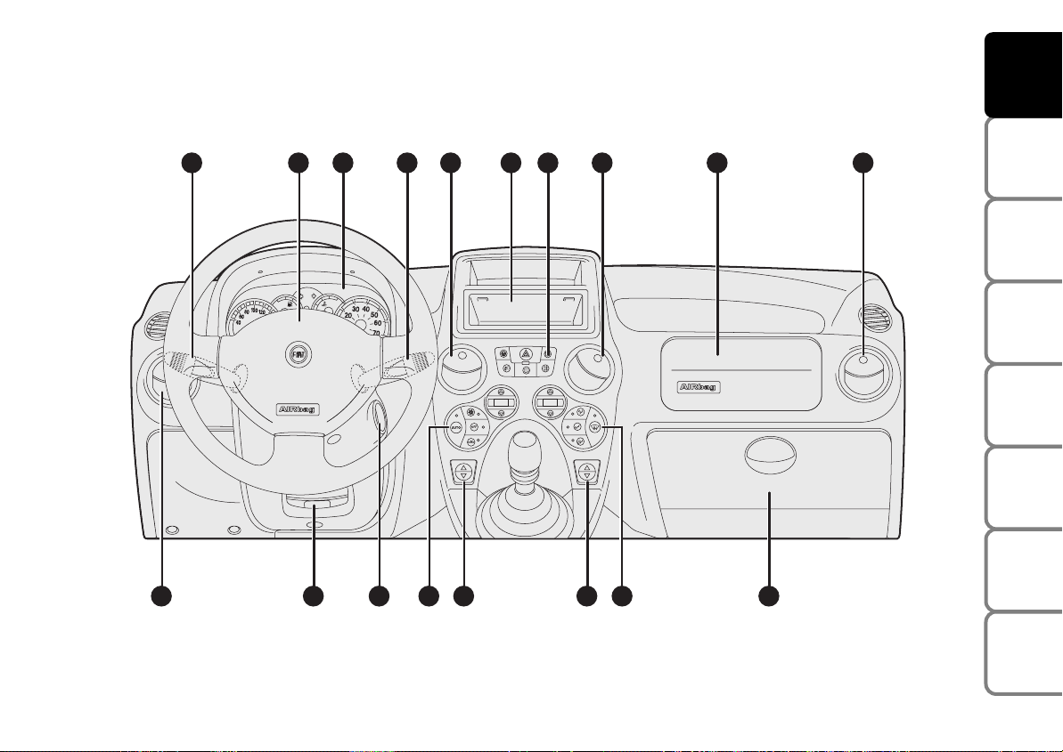
The presence and the position of the instruments and warning lights may vary according to the versions.
Left-hand drive versions
fig. 1
F0G0001m
DASHBOARD
AND CONTROLS
SAFETY
DEVICES
OF THE CAR
CORRECT USE
WARNING
MESSAGES
LIGHTS AND
IN AN
EMERGENCY
CAR
MAINTENANCE
TECHNICAL
SPECIFICATIONS
1. Light and direction indicator stalk - 2. Steering wheel with air bag - 3. Instrument panel - 4. Windscreen/rear window wiper lever
- 5. Central air vents - 6. Sound system compartment - 7. Various controls - 8. Passenger’s air bag - 9. Right-hand side air vent -
10. Glove compartment - 11. Air distribution controls - 12. Right power window control - 13. Left power window control - 14. Air
conditioner controls - 15. Ignition switch - 16. Steering wheel adjusting lever - 17. Left-hand side air vent.
INDEX
5
Page 8
DASHBOARD
C
H
F
E
AND CONTROLS
SAFETY
DEVICES
OF THE CAR
CORRECT USE
WARNING
MESSAGES
LIGHTS AND
IN AN
EMERGENCY
CAR
MAINTENANCE
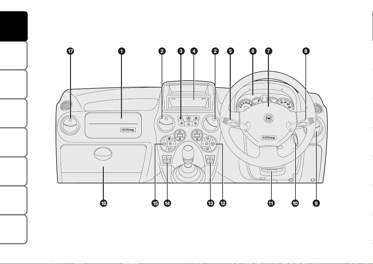
Right-hand drive versions
F0G0002m
TECHNICAL
SPECIFICATIONS
INDEX
6
fig. 2
1. Passenger’s air bag - 2. Central air vents - 3. Various controls - 4. Sound system compartment - 5. Light and direction indicator stalk
- 6. Instrument panel - 7. Steering wheel with air bag - 8. Windscreen/rear window wiper lever - 9. Right-hand side air vent - 10. Ignition switch - 11. Steering wheel adjusting lever - 12. Air distribution controls - 13. Right power window control - 14. Left power
window control - 15. Climate control system controls - 16. Glove compartment - 17. Left-hand side air vent.
Page 9
SYMBOLS
THE FIAT CODE SYSTEM
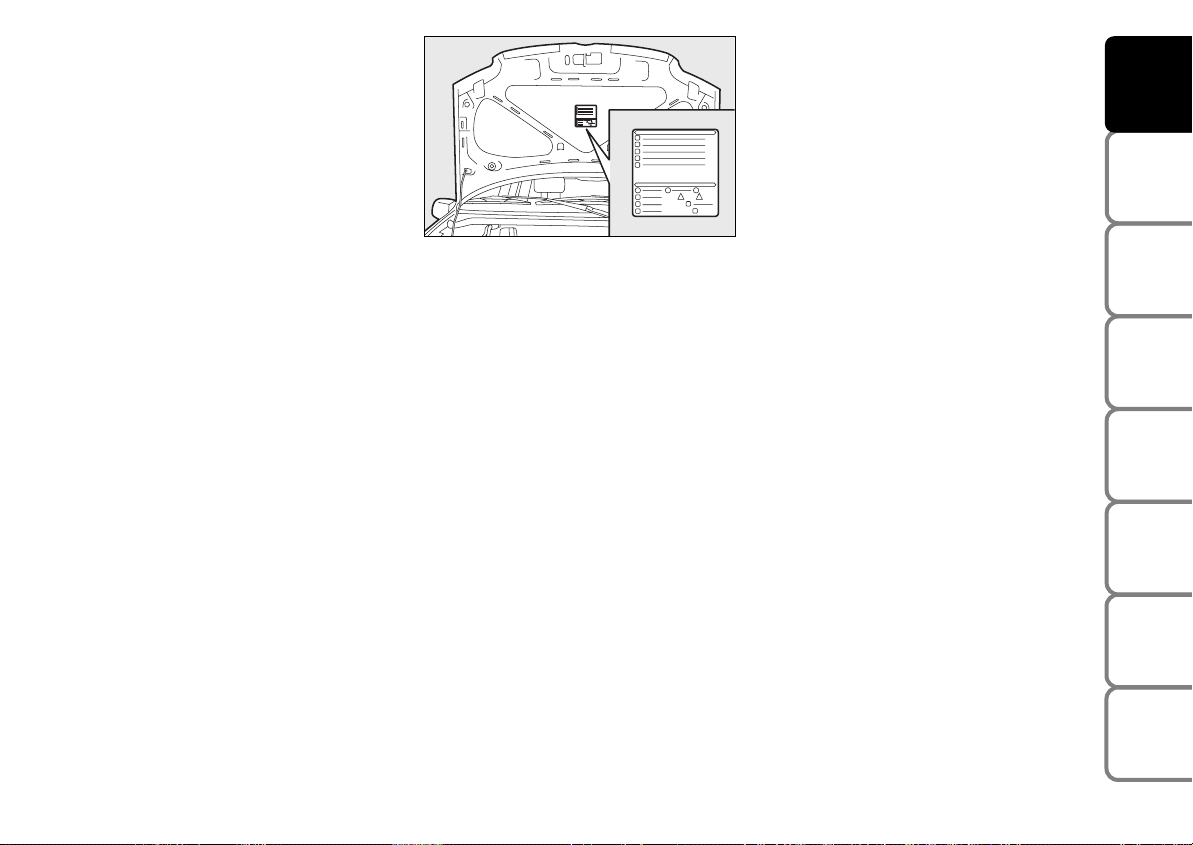
Special coloured labels have been attached
near or actually on some of the components of your Fiat Panda. These labels bear
symbols that remind you of the precautions to be taken as regards that particular component.
fig. 3
F0G0003m
The plate summarising the symbols used
can be found under the bonnet fig. 3.
To further protect your car from theft, it
has been fitted with an engine immobilising
system. This system is automatically activated when the ignition key is removed.
An electronic device, in fact, is fitted in each
ignition key grip. The device transmits a radio-frequency signal when the engine is
started through a special aerial built into the
ignition switch. The modulate signal, which
changes each time the engine is started, is
the password by means of which the control unit recognises the key and enables to
start the engine.
OPERATION
Each time the car is started turning the ignition key to MAR, the Fiat CODE system
control unit sends a recognition code to
the engine control unit to deactivate the inhibitor.
The code is sent only if the system control unit has recognised the code transmitted from the key.
Each time the ignition key is turned to the
STOP position, the Fiat CODE system
deactivates the functions of the engine
electronic control unit.
If the code has not been recognised correctly, the instrument panel warning light
turns on.
Y
DASHBOARD
AND CONTROLS
SAFETY
DEVICES
OF THE CAR
CORRECT USE
WARNING
MESSAGES
LIGHTS AND
IN AN
EMERGENCY
CAR
MAINTENANCE
TECHNICAL
SPECIFICATIONS
INDEX
7
Page 10
DASHBOARD
AND CONTROLS
SAFETY
DEVICES
OF THE CAR
CORRECT USE
WARNING
MESSAGES
LIGHTS AND
IN AN
EMERGENCY
CAR
MAINTENANCE
In this case, the key should be moved to
the STOP position and then back to
MAR; if the lock continues, possibly try
again with the other key provided with the
car. If it is still not possible to start the car,
follow the instructions given in the section
“In an emergency” and then contact a Fiat Dealership.
IMPORTANT Every key has its own code,
which must be memorised by the system
control unit. To memorise new keys, up
to a maximum of eight, apply solely to Fiat Dealership.
Warning light
coming on when
Y
driving
❒
If the warning light Yturns on, this
means that the system is running a selftest (for example for a voltage drop).
At the first stop, turn the ignition key
to STOP and then back to MAR: if no
failure is detected, warning light
will not come on.
❒
If the warning light Ystays on, repeat
the procedure described previously
leaving the key at STOP for over 30
seconds. Should the inconvenience persists, contact a Fiat Dealership.
❒
If the warning light Ystays on this
means that the code has not been
recognised. In this case the key should
be moved to the STOP position and
then back to MAR; if the lock continues, possibly try again with the other
keys provided with the car. If it is still
not possible to start the car, follow the
instructions given in section “In an
emergency” and then contact a Fiat
Dealership.
THE KEYS
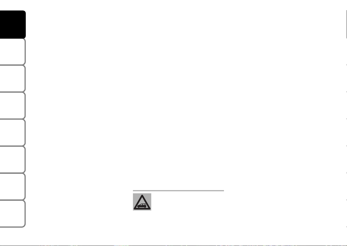
CODE CARD fig. 4
The car is delivered with two copies of the
key, and the CODE card which bears the
following:
Y
A the electronic code to be used for
emergency starting (see “Emergency
starting” in section “Correct use of the
car”).
B the mechanical key code to be given to
the Fiat Dealership when ordering duplicate keys.
Make sure you have the electronic code
A with you at all times in the event you
have to perform an emergency start-up.
IMPORTANT In order to ensure perfect
efficiency of the electronic devices contained inside the keys, they should never
be exposed to direct sunlight.
TECHNICAL
SPECIFICATIONS
INDEX
8
The electronic components
inside the key may be damaged if the key is submitted to
sharp knocks.
Page 11
DASHBOARD
AND CONTROLS
SAFETY
DEVICES
fig. 4
F0G0004m
All the keys and the CODE
card must be handed over to
the new owner when selling
the car.
fig. 5
KEY WITHOUT REMOTE
CONTROL fig. 5
The metal insert A operates:
❒
the ignition switch;
❒
the door and the tailgate locks;
❒
the fuel filler cap locking/unlocking
(where provided);
❒
the switch to deactivate the passenger’s
air bag (where provided).
F0G0188m
fig. 6
F0G0006m
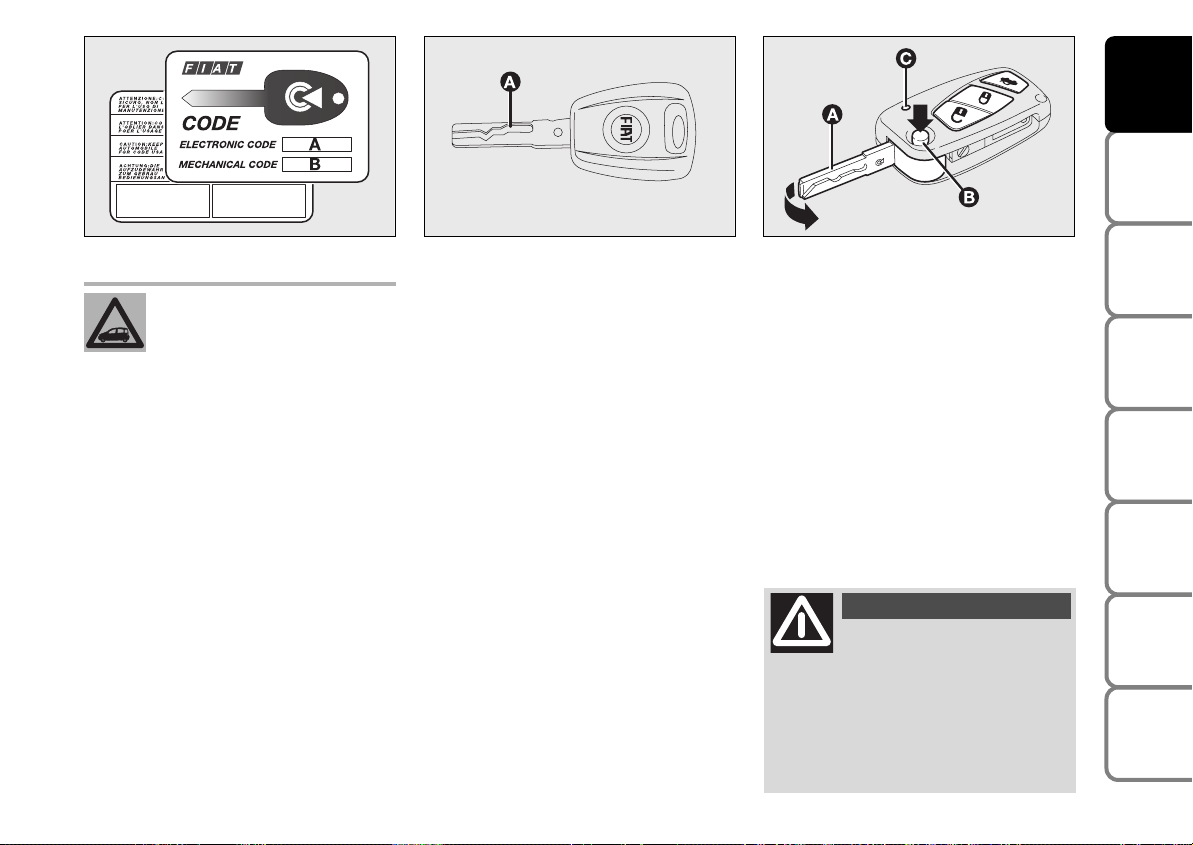
KEY WITH REMOTE CONTROL
(where provided) fig. 6 - fig. 6a
The metal insert A operates:
❒
the ignition switch;
❒
the door and the tailgate locks;
❒
the fuel filler cap locking/unlocking
(where provided);
❒
the switch to deactivate the passenger’s
air bag (where provided).
Press button B to open/to close the met-
al insert.
WARNING
Button B should only be
pressed when the key is
away from the body, in particular
from the eyes and from objects that
can be spoilt (e.g. clothes). Make sure
the key can never be touched by others, especially children, who may inadvertently press the button.
OF THE CAR
CORRECT USE
WARNING
LIGHTS AND
IN AN
EMERGENCY
CAR
MAINTENANCE
TECHNICAL
SPECIFICATIONS
INDEX
9
MESSAGES
Page 12

DASHBOARD
AND CONTROLS
SAFETY
DEVICES
OF THE CAR
CORRECT USE
WARNING
MESSAGES
LIGHTS AND
IN AN
EMERGENCY
CAR
MAINTENANCE
fig. 6/a
F0G0221m
Opening the doors
and the tailgate
Briefly press button Ë: for remote unlocking of doors and tailgate, timed switching of ceiling lights and double flashing of
direction indicators (for versions/markets
where provided).
Doors will be unlocked automatically if the
fuel inertial cut-off switch comes into operation.
Locking the doors and the tailgate
Briefly press (over 1 second) button Á: for
remote locking of doors and tailgate,
switching off of the internal ceiling light and
single flashing of direction indicators
(where provided).
If one of the doors remains open, all doors
will be closed and immediately re-opened;
in this case make sure all doors are locked
correctly and repeat the door lock procedure.
If 20 km/h speed is exceeded, the doors
will be locked automatically provided the
special function is set (only with reconfigurable multifunction display on versions
where provided).
Opening the tailgate
by the remote control
Press and keep button R pressed for
over 1 second to open the tailgate by remote control.
Tailgate opening is accompanied by the direction indicators flashing twice.
IMPORTANT If the remote control does
not work properly, it is still possible to
carry out the above mentioned operations
by using the metal insert of the key.
TECHNICAL
SPECIFICATIONS
INDEX
10
Page 13
DASHBOARD
AND CONTROLS
SAFETY
DEVICES
fig. 7
F0G0189m
REQUEST FOR ADDITIONAL
REMOTE CONTROLS
The system can recognise up to 8 keys
with incorporated remote control. Should
a new key with remote control be necessary, contact directly a Fiat Dealership,
taking with you the CODE card, a personal identity document and the car’s
ownership documents.
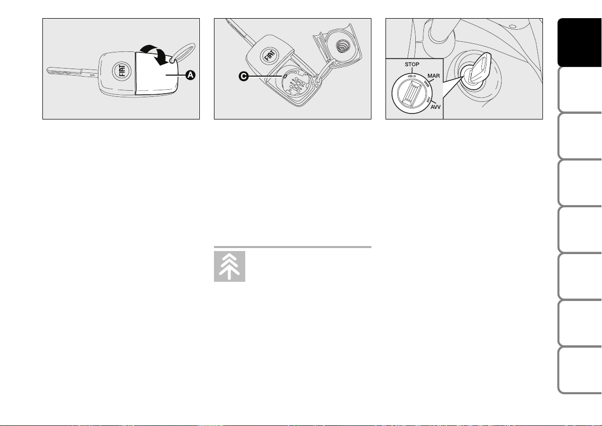
REPLACING THE BATTERY
OF THE KEY WITH REMOTE
CONTROL
If, when pressing button Ë, Á, or R, the
led on the key flashes briefly only once,
the battery should be replaced with an
equivalent one that can be purchased at
common stores.
Battery replacement:
❒
open the snap-fitted lid A-fig. 7 as
shown by the arrow
fig. 8
❒
remove the exhaust battery and replace
F0G0191m
it making sure that the bias is correct
(positive pole + up)
❒
new battery shall be fitted under catch
C-fig. 8; then refit the lid and press it
down until hearing the locking click.
Used batteries are harmful to
the environment. They should
be disposed of as specified by
law in the special containers
provided, or take them to a Fiat Dealership, which will deal with their disposal.
fig. 9
F0G0026m
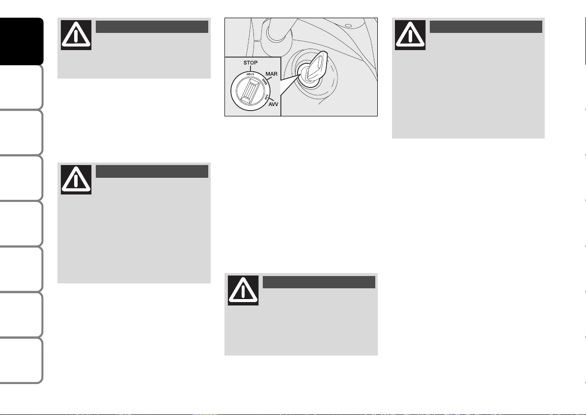
IGNITION SWITCH fig. 9
The key can be turned to 3 different positions:
❒
STOP: engine off, key can be removed,
steering column locked. Certain electrical devices (e.g. sound system, central door locking, etc.) can work
❒
MAR: driving position. All electrical devices are powered
❒
AVV: engine starting.
The ignition switch is fitted with a safety
mechanism that, in the event the engine is
not started, turns back the ignition key to
STOP before repeating the starting operation.
OF THE CAR
CORRECT USE
WARNING
LIGHTS AND
IN AN
EMERGENCY
CAR
MAINTENANCE
TECHNICAL
SPECIFICATIONS
INDEX
11
MESSAGES
Page 14
DASHBOARD
AND CONTROLS
SAFETY
DEVICES
OF THE CAR
CORRECT USE
WARNING
MESSAGES
LIGHTS AND
IN AN
EMERGENCY
CAR
MAINTENANCE
TECHNICAL
SPECIFICATIONS
WARNING
If the ignition device is tam-
pered with (e.g. attempted
theft), have it checked over by a Fiat
Dealership.
WARNING
When getting out of the car,
always remove the key to
prevent any occupants from accidentally activating the controls. Remember to engage the handbrake. If
the car is parked on uphill slope, engage the first gear; if the car is facing downhill, engage the reverse gear.
Never leave unsupervised children in
the car.
fig. 10
F0G0026m
STEERING COLUMN LOCK
fig. 10
Engaging
When the key is at STOP remove the key
and turn the steering wheel until it locks.
Disengaging
Rock the steering wheel slightly as you
turn the ignition key to MAR.
WARNING
Never remove the ignition
key while the car is moving.
The steering wheel would automatically lock as soon as you try to turn
it. This also applies when the car is
being towed.
WARNING
It is absolutely forbidden to
carry out whatever aftermarket operation involving steering
system or steering column modifications (e.g.: installation of anti-theft
device) that could badly affect performance and safety, cause the lapse
of warranty and also result in noncompliance of the car with homologation requirements.
INDEX
12
Page 15
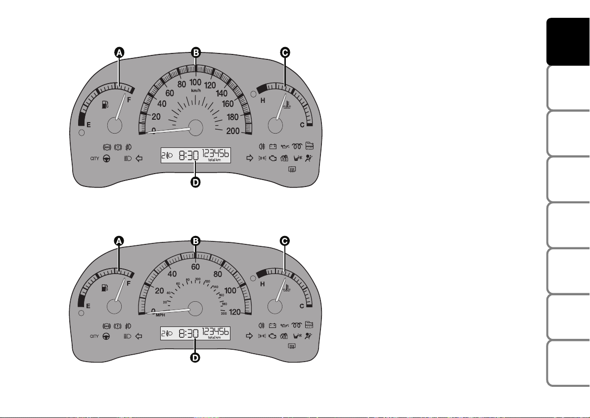
INSTRUMENT PANEL
Actual-Active VERSIONS
A Fuel level gauge with reserve warning
light
B Speedometer (speed indicator)
C Engine coolant temperature gauge and
excessive temperature warning light
D Digital display
Warning lights m and c are only pro-
vided on Diesel versions.
DASHBOARD
AND CONTROLS
SAFETY
DEVICES
OF THE CAR
CORRECT USE
fig. 11 - Left-hand drive versions
fig. 12 - Right-hand drive versions
F0G0250m
F0G0251m
WARNING
IN AN
CAR
TECHNICAL
INDEX
13
MESSAGES
LIGHTS AND
EMERGENCY
MAINTENANCE
SPECIFICATIONS
Page 16

DASHBOARD
AND CONTROLS
SAFETY
DEVICES
OF THE CAR
CORRECT USE
WARNING
MESSAGES
LIGHTS AND
IN AN
EMERGENCY
CAR
MAINTENANCE
Dynamic VERSIONS
A Speedometer (speed indicator)
B Fuel level gauge with reserve warning
light
C Engine coolant temperature gauge and
excessive temperature warning light
D Rev counter
E Multifunction display
Warning lights m and c are only provided on Diesel versions.
F0G0252m
fig. 13 - Left-hand drive versions
TECHNICAL
SPECIFICATIONS
INDEX
14
F0G0253m
fig. 14 - Right-hand drive versions
Page 17
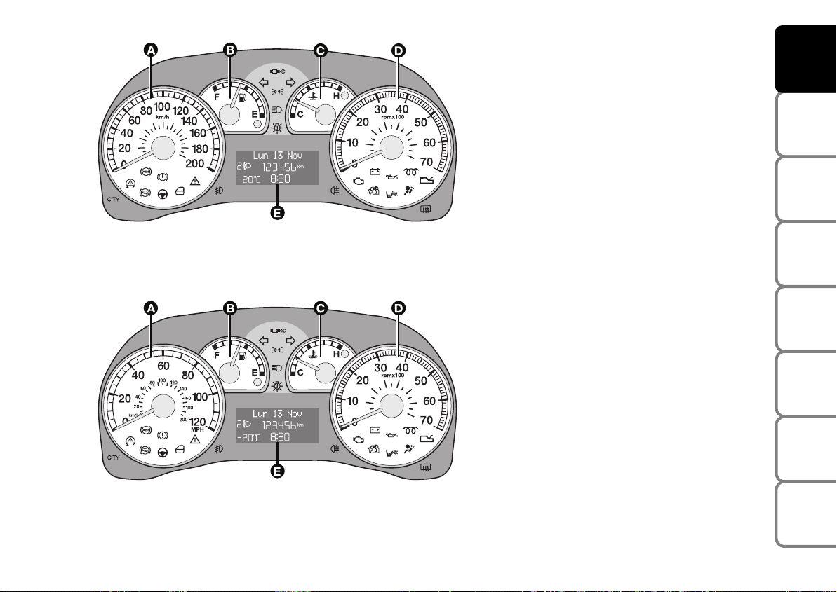
fig. 15 - Left-hand drive versions
F0G0635m
Emotion VERSIONS
A Speedometer (speed indicator)
B Fuel level gauge with reserve warning
light
C Engine coolant temperature gauge and
excessive temperature warning light
D Rev counter
E Reconfigurable multifunction display
Warning light
is only provided on
m
Diesel versions.
Warning light t is only provided on ver-
sions fitted with Dualogic gearbox (see
Supplement “Dualogic” attached to this
Owner Handbook).
DASHBOARD
AND CONTROLS
SAFETY
DEVICES
OF THE CAR
CORRECT USE
WARNING
MESSAGES
LIGHTS AND
IN AN
EMERGENCY
CAR
MAINTENANCE
fig. 16 - Right-hand drive versions
F0G0636m
TECHNICAL
INDEX
15
SPECIFICATIONS
Page 18
INSTRUMENTS
DASHBOARD
AND CONTROLS
SAFETY
DEVICES
OF THE CAR
CORRECT USE
WARNING
MESSAGES
LIGHTS AND
IN AN
EMERGENCY
CAR
MAINTENANCE
TECHNICAL
SPECIFICATIONS
Instrument background color and type
may vary according to the version.
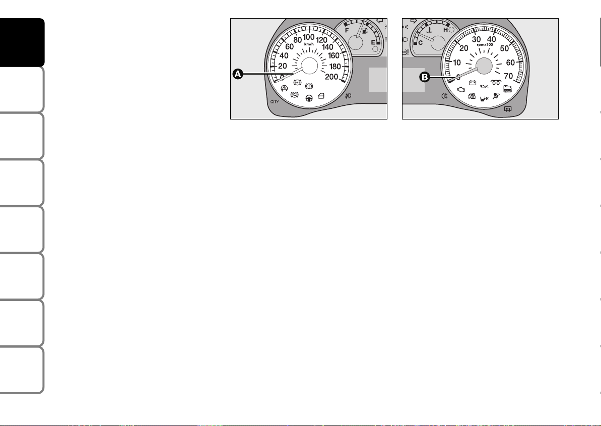
fig. 17
F0G0146m
SPEEDOMETER
(SPEED INDICATOR) fig. 17
The indicator A shows the car speed
(speedometer).
fig. 18
F0G0256m
REV COUNTER fig. 18
The indicator B shows the engine rev
number.
IMPORTANT The electronic injection
control system gradually shuts off the flow
of fuel when the engine is “over-revving”
resulting in a gradual loss of engine power.
When the engine is idling, the rev counter
may indicate a gradual or sudden highering of the speed.
This is normal as it takes place during normal operation, for example when activating the climate control system or the fan.
In particular a slow change in the speed
preserves the battery charge.
INDEX
16
Page 19
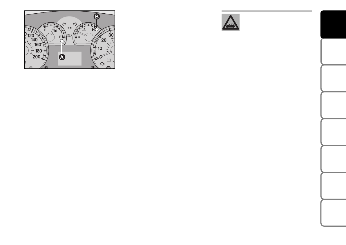
fig. 19
F0G0148m
FUEL LEVEL GAUGE fig. 19
This shows the amount of fuel left in the
fuel tank.
E tank empty.
F full tank.
The reserve warning light A to indicate
that approximately 5 litres of fuel are left
in the tank.
Do not travel with the fuel tank almost
empty: the gaps in fuel delivery could damage the catalyst.
IMPORTANT The needle sets to E with
warning light A flashing to indicate that the
system is failing. In this event contact Fiat
Dealership to have the system checked.
ENGINE COOLANT
TEMPERATURE GAUGE fig. 19
This shows the temperature of the engine
coolant fluid and begins working when the
fluid temperature exceeds approx. 50°C.
Under normal conditions, the needle
should hover around the middle of the
scale according to the working conditions.
C Low engine coolant temperature.
H High engine coolant temperature.
The turning on of the warning light B (on
certain versions with a message on the reconfigurable multifunction display) indicates that the coolant fluid temperature is
too high; in this case, stop the engine and
contact a Fiat Dealership.
If the needle reaches the red
area, stop the engine immediately and contact a Fiat
Dealership.
DASHBOARD
AND CONTROLS
SAFETY
DEVICES
OF THE CAR
CORRECT USE
WARNING
MESSAGES
LIGHTS AND
IN AN
EMERGENCY
CAR
MAINTENANCE
TECHNICAL
SPECIFICATIONS
17
INDEX
Page 20
DIGITAL DISPLAY
DASHBOARD
AND CONTROLS
SAFETY
DEVICES
OF THE CAR
CORRECT USE
WARNING
MESSAGES
LIGHTS AND
IN AN
EMERGENCY
CAR
MAINTENANCE
TECHNICAL
SPECIFICATIONS
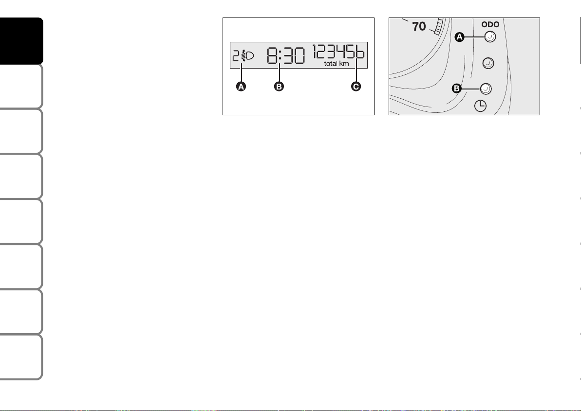
“STANDARD” SCREEN fig. 20
The standard screen shows the following
indications:
A Headlight aiming position (only with
dipped beam headlights on).
B Clock (always displayed, even with ig-
nition key removed and front doors
closed).
C Odometer (covered km or miles).
fig. 20
F0G0015m
Note With key removed (when opening
one of the front doors) the display will
turn on and show for a few seconds the
km or mi covered.
fig. 21
F0G027m
CONTROL BUTTONS fig. 21
A Press briefly for switching from total
to partial km/miles.
Long press (over 2 seconds) to reset
partial km/miles.
B Set clock.
SETTING THE CLOCK fig. 21
To set the clock hour press button B.
Every press on the button increases or decreases by one unit. Keeping the corresponding button pressed obtains automatic fast increase or decrease. When you
are near the required value, release the
button and complete adjustment with single presses.
INDEX
18
Page 21
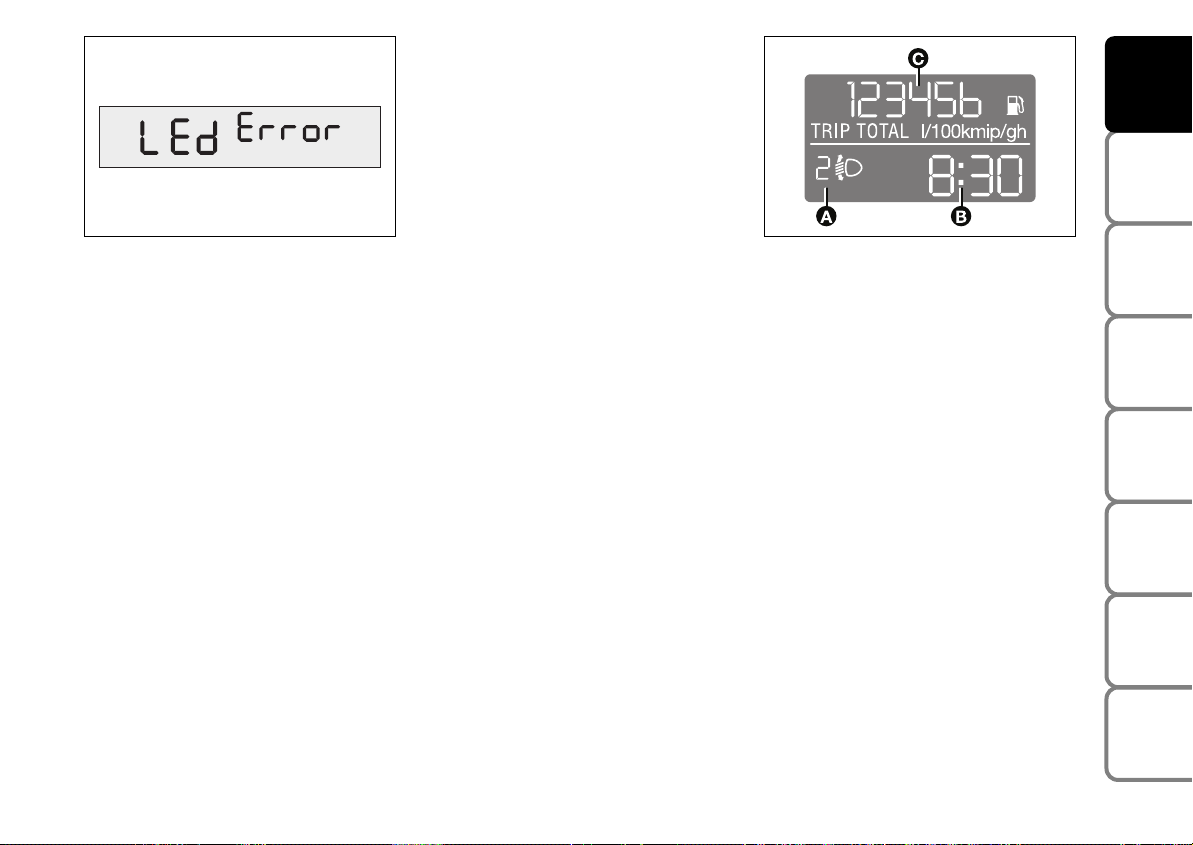
fig. 22
F0G0185m
WARNING LIGHT TEST fig. 22
The following warning lights are tested:
❒
handbrake on/low brake fluid level;
❒
ABS and EBD systems (where provided);
❒
ESP system (where provided);
❒
“Dualdrive” electrical power steering
failure (where provided).
The test is automatically run when the ignition key is turned to MAR and during
normal operation when a fault is signalled.
At the end of the initial warning light test,
the message “LEd Error” will flash on the
display for 10 seconds if a faulty warning
light is found.
MULTIFUNCTION
DISPLAY
STANDARD SCREEN fig. 23
The standard screen shows the following
indications:
A Headlight aiming position (only with
dipped beam headlights on).
B Clock.
C Odometer (covered km or miles).
fig. 23
F0G0016m
Note With key removed (when opening
one of the front doors) the display will
turn on and show for a few seconds the
clock and the km or mi covered.
DASHBOARD
AND CONTROLS
SAFETY
DEVICES
OF THE CAR
CORRECT USE
WARNING
MESSAGES
LIGHTS AND
IN AN
EMERGENCY
CAR
MAINTENANCE
TECHNICAL
SPECIFICATIONS
19
INDEX
Page 22
DASHBOARD
AND CONTROLS
SAFETY
DEVICES
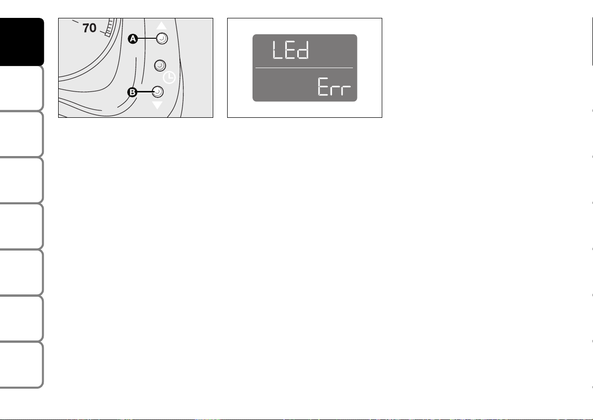
The test is automatically run when the key
is turned to MAR and during normal operation when a fault is signalled. At the end
of the initial warning light test, the message LEd Err will flash on the display for
10 seconds if a faulty warning light is found.
OF THE CAR
CORRECT USE
WARNING
MESSAGES
LIGHTS AND
IN AN
EMERGENCY
CAR
MAINTENANCE
TECHNICAL
SPECIFICATIONS
INDEX
20
fig. 25
F0I0142m
SETTING THE CLOCK fig. 25
To adjust the time, press button A to increase minutes, button B to decrease minutes. Every press on the button increases or decreases by one unit. Keeping the
corresponding button pressed obtains automatic fast increase or decrease. When
you are near the required value, release
the button and complete adjustment with
single presses.
fig. 26
F0G0152m
WARNING LIGHT TEST fig. 26
The following warning lights are tested:
❒
handbrake on/low brake fluid level;
❒
ABS and EBD systems (where provided);
❒
ESP system (where provided);
❒
“Dualdrive” electrical power steering
failure.
Page 23
RECONFIGURABLE
MULTIFUNCTION
DISPLAY
(where provided)
DASHBOARD
AND CONTROLS
The car can be provided with the reconfigurable multifunction display that shows
useful information, according to the previous settings made, necessary when driving.
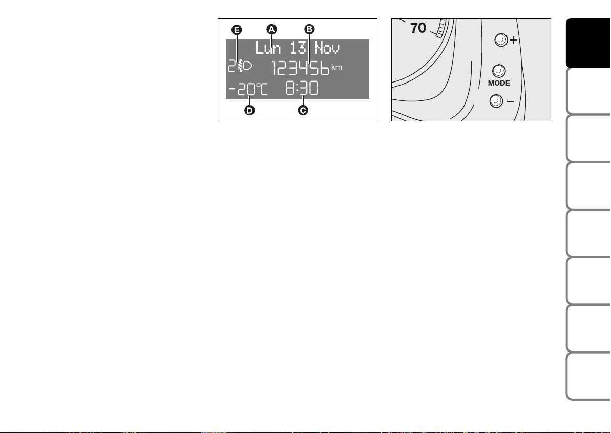
“STANDARD” SCREEN fig. 27
The standard screen shows the following
indications:
A Date
B Odometer (covered km or miles)
C Clock
D External temperature
E Headlight aiming position (only with
dipped beam headlights on).
Note When opening one of the front
doors, the display will turn on and show
for a few seconds the clock and the km or
mi covered.
fig. 27
CONTROL BUTTONS fig. 28
F0G0017m
+ To scroll the displayed menu and the
related options upwards or to increase
the value displayed .
MODE Brief press to open the menu
and/or to move to next screen
or to confirm the the option
required.
Long press to go back to the
standard screen.
– To scroll the displayed menu and the
related options downwards or to decrease the value displayed.
fig. 28
Note Buttons + and – activate different
functions according to the following situations:
To adjust light inside the passenger
compartment
– to adjust instrument panel, sound system and automatic climate control system
display brightness when standard screen
is active.
Setup menu
– to scroll the menu options upwards and
downwards;
– to increase or decrease values during settings.
F0G0630m
SAFETY
DEVICES
OF THE CAR
CORRECT USE
WARNING
MESSAGES
LIGHTS AND
IN AN
EMERGENCY
CAR
MAINTENANCE
TECHNICAL
SPECIFICATIONS
INDEX
21
Page 24

DASHBOARD
AND CONTROLS
SAFETY
DEVICES
OF THE CAR
CORRECT USE
WARNING
MESSAGES
LIGHTS AND
IN AN
EMERGENCY
CAR
MAINTENANCE
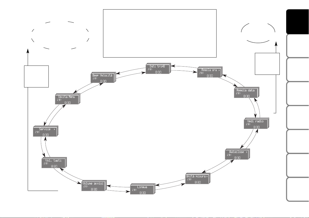
SETUP MENU fig. 29
The menu comprises a series of functions
arranged in a “circular fashion” which can
be selected through buttons + and – to
access the different select operations and
settings (setup) given in the following paragraphs.
For certain options (Hour and Unit) a submenu is provided.
The setup menu can be activated by pressing briefly button MODE.
Single presses on buttons + or – will scroll
the setup menu options.
Handling modes differ with each other according to the characteristic of the option
selected.
Selecting an option of the main menu without submenu:
– press briefly button MODE to select
the main menu option to set;
– press buttons + or – (by single presses) to select the new setting;
– press briefly button MODE to store the
new setting and to go back to the main
menu option previously selected.
Selecting an option of the main menu with
submenu:
– press briefly button MODE to display
the first submenu option;
– press buttons + or – (by single presses) to scroll all the submenu options;
– press briefly button MODE to select
the displayed submenu option and to open
the relevant setup menu;
– press buttons + or – (by single presses) to select the new setting for this submenu option;
– press briefly button MODE to store the
new setting and to go back to the previously selected submenu option.
Selecting “Date” and “Set Clock”:
– briefly press button MODE to select
the first value to change (e.g. hours /minutes or year / month / day);
– operate buttons + or – (by single press)
to select the new setting;
– briefly press button MODE to store the
new setting and to go to the next setup
menu option, if this is the last one you will
go back to the previously selected option of
the main menu.
Press button MODE for long:
– to quit the set up menu if you are in the
main menu;
– to quit the main menu if you are at another point of the menu (e.g.: at submenu
option setting level, at submenu level or
at main menu option setting level);
– to save only the settings stored yet (and
confirmed by pressing button MODE).
The setup menu displaying is timed; when
quitting the menu due to timing expiry,
only settings stored yet by the user (and
confirmed by pressing briefly button
MODE) will be saved.
TECHNICAL
SPECIFICATIONS
INDEX
22
Page 25
Example:
Italiano
Nederland
Polski
MODE
briefly
press
button
+
Português
+
Deutsch
–
–
English
Français
SERVICE
Español
+
–
EXIT MENU
Briefly press button MODE to start surfing from the
standard screen. To surf the menu use buttons + or –.
Note For safety reasons, when the car is running, it is
possible to access only the reduced menu (for setting
the “Beep limit”). When the car is stationary access to
the whole menu is enabled. On cars provided with the
Connect Nav+ system, many functions are displayed on
the navigator display.
+
+
–
TRIP B DATA
–
SPEED LIM.
SET TIME
SET DATE
AUTOCLOSE
Example:
+
–
SEE RADIO
Year
–
Day
DASHBOARD
Month
MODE
briefly
press
button
+
–
+
F0G1235g
AND CONTROLS
SAFETY
DEVICES
OF THE CAR
CORRECT USE
WARNING
MESSAGES
LIGHTS AND
IN AN
EMERGENCY
CAR
MAINTENANCE
fig. 29
BUTTON VOL.
+
–
BUZZER VOLUME
+
–
LANGUAGE
UNITS
–
–
TECHNICAL
+
SPECIFICATIONS
–
+
INDEX
23
Page 26

DASHBOARD
AND CONTROLS
SAFETY
DEVICES
OF THE CAR
CORRECT USE
WARNING
MESSAGES
LIGHTS AND
IN AN
EMERGENCY
CAR
MAINTENANCE
TECHNICAL
SPECIFICATIONS
INDEX
Speed limit (Speed Beep)
With this function it is possible to set the
car speed limit (km/h or mph); when this
limit is exceeded the driver is immediately alerted (see section “Warning lights and
messages”).
To set the speed limit, proceed as follows:
– briefly press button MODE, the display
will show the wording (Speed Beep);
– press button + or – to select speed lim-
it activation (On) or deactivation (Off);
– if the function has been activated (On),
press buttons + or – to select the required speed limit and then press MODE
to confirm.
Note The possible setting is between 30 and
200 km/h, or between 20 and 125 mph depending on the unit set previously (see paragraph “Setting the distance unit (Units)”) described later. Every press on button + / – increases/decreases by 5 units. Keeping the
button + / – pressed obtains the automatic
fast increase or decrease. When you are
near the required setting complete adjustment by single presses.
– briefly press button
MODE en or press
the button for long to go back to the standard screen without storing settings.
To cancel the setting, proceed as follows:
– briefly press button MODE: (On) will
flash on the display;
– press button –: (Off) will flash on the dis-
play;
– briefly press button MODE to go back
to the menu screen or press the button
for long to go back to the standard screen
without storing settings.
Trip B On/Off (tripB data)
Through this option it is possible to activate (On) or deactivate (Off) the Trip B
(partial trip).
For further information see “Trip computer”.
For activation / deactivation, proceed as
follows:
– briefly press button MODE: (On) or
(Off) will flash on the display (according to
previous setting);
– press button + or – for setting;
– briefly press button MODE to go back
to the menu screen or press the button
for long to go back to the standard screen
without storing settings.
Set clock (Set time)
This function enables to set the clock
through two sub-menus: “Time” and
“Mode”.
Proceed as follows:
– briefly press button MODE, the display
will show the two sub-menus “Time” and
“Mode”;
– press button + or – to surf the two sub-
menus;
– select the required option and then
press button MODE briefly;
– if selecting “Time”, briefly press button
MODE, “hours” will flash on the display;
– press button + or – for setting;
– briefly press button MODE, “minutes”
will flash on the display;
– press button + or – for setting;
24
Page 27

– if selecting “Mode”: briefly press button
MODE , “24h” or “12h” mode will flash
on the display;
– press button + or – to select “24h” or
“12h”.
After setting, briefly press button MODE
to go back to the submenu screen or
press the button for long to go back to the
main menu screen without storing settings.
– Press again button MODE for long to
go back to the standard screen or to the
main menu according to the current menu
level displayed.
Set date (Set Date)
This function enables to update the date
(day - month - year).
To correct the date proceed as follows:
– briefly press button MODE: “day” will
flash on the display;
– press button + or – for setting;
– briefly press button MODE: “month”
will flash on the display;
– press button + or – for setting;
– briefly press button MODE: “year” will
flash on the display;
– press button + or – for setting.
Note Every press on button + or – in-
creases/decreases by 1 unit. Keeping the
button pressed obtains automatic fast increase or decrease. When you are near
the required setting complete adjustment
by single presses.
– briefly press button MODE to go back
to the menu screen or press the button
for long to go back to the standard screen
without storing settings.
Audio repetition (See radio)
With this function the display repeats information relevant to the sound system.
– Radio: selected radio station frequency
or RDS message, automatic tuning activation or AutoSTore;
– audio CD, MP3 CD: track number;
– CD Changer: CD number and track
number;
– Tape: operating mode.
To activate (On) or to deactivate (Off)
sound system info displaying proceed as
follows:
– briefly press button MODE: (On) or
(Off) will flash on the display (according to
previous setting);
– press button + or – for setting;
– briefly press button MODE to go back
to the menu screen or press the button
for long to go back to the standard screen
without storing settings.
DASHBOARD
AND CONTROLS
SAFETY
DEVICES
OF THE CAR
CORRECT USE
WARNING
MESSAGES
LIGHTS AND
IN AN
EMERGENCY
CAR
MAINTENANCE
TECHNICAL
INDEX
25
SPECIFICATIONS
Page 28

DASHBOARD
AND CONTROLS
SAFETY
DEVICES
OF THE CAR
CORRECT USE
WARNING
MESSAGES
LIGHTS AND
IN AN
EMERGENCY
CAR
MAINTENANCE
Automatic door locking
with car
running (Autoclose)
When activated (On), this function locks
automatically the doors when the car
speed exceeds 20 km/h.
To activate (On) or to deactivate (Off) this
function proceed as follows:
– briefly press button MODE to go back
to the sub-menus;
– briefly press button MODE: (On) or
(Off) will flash on the display (according to
previous setting);
– press button + or – for setting;
– briefly press button MODE to go back
to the submenu screen or press the button for long to go back to the main menu
screen without storing settings;
– press again button MODE for long to
go back to the standard screen or to the
main menu according to the current menu
level displayed.
Set unit (Units)
With this function it is possible to set the
units through three sub-menus: “Distances”,
“Consumption” and “Temperature”.
To set the required unit proceed as follows:
– briefly press button MODE to display the
three sub-menus;
– press button + or – to surf the three submenus;
– select the required sub-menu and then
press briefly button MODE;
– if selecting “Distances”: briefly press button
MODE, the display will show “km” or
“mi” (according to previous setting);
– press button + or – for setting;
– if selecting “Consumption”: briefly press but-
ton MODE, the display will show “km/l”,
“l/100km” or “mpg” (according to previous
setting);
If the distance unit set is “km” the fuel consumption unit will be displayed in km/l or
l/100km.
If the distance unit set is “mi” the fuel consumption unit will be displayed in “mpg”.
– press button + or – for setting;
– if selecting “Temperature”: briefly press but-
ton MODE, the display will show “°C” or
“°F” (according to previous setting);
– press button + or – for setting;
After setting, briefly press button MODE
to go back to the submenu screen or
press the button for long to go back to the
main menu screen without storing settings.
– Press again button MODE for long to
go back to the standard screen or to the
main menu according to the current menu
level displayed.
TECHNICAL
SPECIFICATIONS
INDEX
26
Page 29

Selecting the language
(Set Language)
Display messages can be shown in different languages: Italian, German, English,
Spanish, French, Portuguese, Polish and
Dutch.
To set the required language proceed as
follows:
– briefly press button MODE: the previously set “language” will flash on the display;
– press button + or – for setting;
– briefly press button MODE to go back
to the menu screen or press the button
for long to go back to the standard screen
without storing settings.
Adjusting the failure/warning
buzzer volume (Buzzer Volume)
With this function the volume of the
buzzer accompanying any failure/warning
indication can be adjusted according to 8
levels.
To set the required the volume proceed
as follows:
– briefly press button MODE: the previously set volume “level” will flash on the
display;
– press button + or – for setting;
– briefly press button MODE to go back
to the menu screen or press the button
for long to go back to the standard screen
without storing settings.
Adjusting the button volume
(Vol. key)
With this function the volume of the
roger-beep accompanying the activation
of buttons MODE, + and – can be adjusted according to 8 levels.
To set the required the volume proceed
as follows:
– briefly press button MODE: the previously set volume “level” will flash on the
display;
– press button + or – for setting;
– briefly press button MODE to go back
to the menu screen or press the button
for long to go back to the standard screen
without storing settings.
DASHBOARD
AND CONTROLS
SAFETY
DEVICES
OF THE CAR
CORRECT USE
WARNING
MESSAGES
LIGHTS AND
IN AN
EMERGENCY
CAR
MAINTENANCE
TECHNICAL
INDEX
27
SPECIFICATIONS
Page 30

DASHBOARD
AND CONTROLS
SAFETY
DEVICES
OF THE CAR
CORRECT USE
WARNING
MESSAGES
LIGHTS AND
IN AN
EMERGENCY
CAR
MAINTENANCE
Scheduled Servicing (Service)
Through this function it is possible to display information connected to proper car
servicing.
Proceed as follows:
– briefly press button MODE: service in
km or mi, according to previous setting,
will be displayed (see paragraph “Units”);
– briefly press button MODE to go back
to the menu screen or press the button
for long to go back to the standard screen.
Note The “Service Schedule includes car
maintenance every 20,000 km (or 12,000
mi); this is shown automatically, with the
ignition key at MAR, starting from 2,000
km (or the equivalent value in miles) from
this deadline and it is shown again every
200 km (or the equivalent value in miles).
Below 200 km servicing indications are
displayed more frequently. Service indications will be displayed km or mi according
to previous unit setting. When a programmed maintenance interval (coupon)
is near to come, turning the ignition key
to MAR, the display will show the message “Service” followed by the number of
km/mi to go before car servicing. Contact
a Fiat Dealership to carry out any service
operation provided by the “Service schedule” and to reset the display.
Exit Menu
This is the last function that closes the circular setting cycle listed in the initial menu
screen.
Briefly press button MODE to go back to
the standard screen without storing settings.
Press button – to return to the first menu
option (Speed Lim.).
TECHNICAL
SPECIFICATIONS
INDEX
28
Page 31

TRIP COMPUTER
(where provided)
General features
The “Trip computer” is provided on cars
fitted with multifunction display or reconfigurable multifunction display. The
“Trip computer” displays information
(with ignition key at MAR) relating to the
operating status of the car. This function
comprises the “General trip” concerning
the “complete mission” of the car (journey) and “Trip B”, (only available on reconfigurable multifunction display), concerning the partial mission of the car; this
latter function (as shown in fig. 31) is “contained” within the complete mission.
Both functions are resettable (reset - start
of new mission).
“General Trip” displays the figures relating to:
– Range to empty
– Trip distance
– Average consumption
– Instant consumption
– Average speed
– Trip time (driving time).
“Trip B” (only available on reconfigurable
multifunction display), displays the figures
relating to:
– Trip distance B
– Average consumption B
– Average speed B
– Trip time B (driving time).
Note The “Trip B” function can be excluded (see paragraph “Trip B On/Off”).
“Range to empty” cannot be reset.
DASHBOARD
AND CONTROLS
SAFETY
DEVICES
OF THE CAR
CORRECT USE
WARNING
MESSAGES
LIGHTS AND
IN AN
EMERGENCY
CAR
MAINTENANCE
TECHNICAL
INDEX
29
SPECIFICATIONS
Page 32

DASHBOARD
AND CONTROLS
SAFETY
DEVICES
OF THE CAR
CORRECT USE
WARNING
MESSAGES
LIGHTS AND
IN AN
EMERGENCY
CAR
MAINTENANCE
Values displayed
Range to empty
This value shows the distance in km (or
mi) that the car can still cover before
needing fuel, assuming that driving conditions are kept unvaried. The display will
show “----” in the following cases:
– value lower than 50 km (or 30 mi)
– car left parked with engine running for
long.
Trip distance
This value shows the distance covered
from the start of the new mission.
Average consumption
This value shows the average consumption from the start of the new mission.
Instant consumption
This value shows instant fuel consumption
(this value is updated second by second).
If parking the car with engine on,
the display will show “----”.
Average speed
This value shows the car average speed as
a function of the overall time elapsed since
the start of the new mission.
Trip time
This value shows the time elapsed since
the start of the new mission.
IMPORTANT Lacking information, Trip
computer values are displayed with “----”.
When normal operating condition is reset, calculation of different units will
restart regularly. Values displayed before
the failure will not be reset.
TRIP button fig. 30
Button TRIP, set on the top of the right
steering column stalk, shall be used (with
ignition key at MAR) to display and to reset the previously described values to start
a new mission:
– short push to display the different values
– long push to reset and then start a new
mission.
New mission
New mission starts after:
– “manual” resetting by the user, by press-
ing the relevant button;
– “automatic” resetting, when the “Trip dis-
tance” reaches 3999.9 km or 9999.9 km
(according to the type of display) or when
the “Trip time” reaches 99.59 (99 hours
and 59 minutes);
– after disconnecting/reconnecting the
battery.
TECHNICAL
SPECIFICATIONS
INDEX
30
Page 33

TRIP
fig. 30
F0G0149m
IMPORTANT The reset operation in the
presence of the screens concerning the
“General Trip” makes it possible to reset
also the “Trip B”. The reset operation in
the presence of the screens concerning
only the “Trip B” makes it possible to reset only the information associated with
this function.
Start of journey procedure
With ignition key at MAR, press and keep
button TRIP pressed for over 2 seconds
to reset.
Exit Trip
To quit the Trip function: keep button
MODE pressed for over 2 seconds.
DASHBOARD
AND CONTROLS
SAFETY
DEVICES
OF THE CAR
CORRECT USE
Reset GENERAL TRIP
End of complete mission
Start of new mission
˙
˙
Reset TRIP B
End of partial mission
Start of new partial mission
fig. 31
TRIP B
GENERAL TRIP
Reset TRIP B
˙
˙
End of partial mission
Start of new
partial mission
TRIP B
Reset TRIP B
˙
˙
End of partial mission
Start of new
partial mission
TRIP B
Reset GENERAL TRIP
End of complete mission
Start of new mission
˙
˙
Reset TRIP B
End of partial mission
Start of new
partial mission
WARNING
IN AN
CAR
TECHNICAL
INDEX
31
MESSAGES
LIGHTS AND
EMERGENCY
MAINTENANCE
SPECIFICATIONS
Page 34

SEATS
DASHBOARD
AND CONTROLS
SAFETY
DEVICES
OF THE CAR
CORRECT USE
WARNING
MESSAGES
LIGHTS AND
IN AN
EMERGENCY
CAR
MAINTENANCE
TECHNICAL
SPECIFICATIONS
FRONT SEATS
WARNING
Only make adjustments
when the car is stationary.
Moving the seat backwards
or forwards fig. 32
Lift the lever A and push the seat forwards
or backwards: in the driving position the
arms should rest on the rim of the steering wheel.
WARNING
Once you have released the
lever, check that the seat is
firmly locked in the runners by trying
to move it back and forth. Failure to
lock the seat in place could result in
the seat moving suddenly and the driver losing control of the car.
fig. 32
F0G0029m
Back rest angle adjustment fig. 33
Turn the knob B.
fig. 33
fig. 34
F0G0030m
F0G0031m
Cushion adjustment
(where provided) fig. 34
Use lever D to raise or lower the back
of the cushion in order to obtain the required comfortable driving position.
INDEX
32
Page 35

The “fully tilted” position
shall only be used with car
stopped and seat moved forward.
DASHBOARD
AND CONTROLS
SAFETY
DEVICES
fig. 35
F0G00257m
REAR SLIDING SEATS
(where provided)
WARNING
Only make adjustments
when the car is stationary.
Adjustments from the passenger
compartment fig. 35
Moving the seat backwards or forwards
Raise lever A taking it in the middle and then
push the seat backwards or forwards. The
seat will lock when releasing the lever.
Back rest angle adjustment
Raise lever B and C to adjust respectively the right and left section of the back
rest.
fig. 36
F0G0258m
Adjustments from the boot fig. 36
Moving the seat backwards or forwards
Raise the central tab D and push the seat
forwards or backwards.
Adjusting/ tilting the seat back rest
Use tab E to adjust or to tilt the right back
rest and tab F to adjust or to tilt the left
back rest.
Guide the back rest during tilting.
WARNING
Once you have released the
lever, check that the seat is
firmly locked in the runners by trying
to move it back and forth. Failure to
lock the seat in place could result in
the seat moving suddenly and the driver losing control of the car.
OF THE CAR
CORRECT USE
WARNING
LIGHTS AND
IIN AN
EMERGENCY
CAR
MAINTENANCE
TECHNICAL
SPECIFICATIONS
INDEX
33
MESSAGES
Page 36

DASHBOARD
AND CONTROLS
SAFETY
DEVICES
OF THE CAR
CORRECT USE
WARNING
MESSAGES
LIGHTS AND
IN AN
EMERGENCY
CAR
MAINTENANCE
HEAD RESTRAINTS
FRONT fig. 37
According to versions front head restraints can be fixed or adjustable in height
(where provided); to adjust head restraints proceed as follows.
❒
To raise: raise the head restraint until
hearing the locking click.
❒
To lower: press button A and lower
the head restraint.
fig. 37
F0G0033m
WARNING
Any adjustment of the head
restraints must be carried
out only with the car stationary and
the engine turned off.
WARNING
Remember that the head re-
straints should be adjusted
to support the back of your head and
not your neck. Only in this position
do they exert their protective action.
WARNING
To optimise head restraint
protective action, adjust the
seat back upright and keep your head
as close as possible to the head restraint.
TECHNICAL
SPECIFICATIONS
INDEX
34
Page 37

REAR fig. 38
According to versions rear head restraints
can be fixed (for 5-seat versions) or adjustable. To use adjustable head restraints,
raise the head restraint from position 2
“position of non use” to position 1 “completely removed”.
To bring it back to the original position
“position of non use”, press button B and
push the head restraint down.
To take them out, press both buttons B
and C, raise them and then remove.
fig. 38
F0G0034m
The particular head restraint shape voluntarily interferes with the passenger’s
back leaning on the rear seat in order to
force him/her to lift the head restraint and
use it correctly.
IMPORTANT Rear seat passengers shall
always set the head restraints in the “completely removed” position.
DASHBOARD
AND CONTROLS
SAFETY
DEVICES
OF THE CAR
CORRECT USE
WARNING
MESSAGES
LIGHTS AND
IIN AN
EMERGENCY
CAR
MAINTENANCE
TECHNICAL
INDEX
35
SPECIFICATIONS
Page 38

STEERING WHEEL
REARVIEW MIRRORS
DASHBOARD
AND CONTROLS
SAFETY
DEVICES
OF THE CAR
CORRECT USE
WARNING
MESSAGES
LIGHTS AND
IN AN
EMERGENCY
CAR
MAINTENANCE
TECHNICAL
SPECIFICATIONS
The steering wheel can be adjusted in
height (where provided).
Release the lever A-fig. 39 pulling it towards the steering wheel, then adjust it in
the most suitable position and lock it pushing the lever A fully forwards.
fig. 39
F0G0061m
WARNING
Any adjustment must be carried out only with the car
stationary and the engine turned off.
DRIVING MIRROR fig. 40
The mirror is fitted with a safety device
that causes it to be released in the event
of a violent crash.
It can be moved using the lever A to two
different positions: normal or antiglare.
INDEX
36
Page 39

DASHBOARD
AND CONTROLS
SAFETY
DEVICES
fig. 40
F0G0036m
DOOR MIRRORS
Manual adjustment fig. 41-42
Use lever A to adjust mirror B from the
passenger compartment.
When required (for example when the
mirror causes difficulty in narrow spaces)
it is possible to fold the mirror moving it
from position 1 (open) to position 2
(closed).
fig. 41
fig. 42
F0G0197m
F0G0040m
WARNING
When driving the mirrors
shall always be in position 1.
On Actual versions, the door mirror shall
be adjusted from the outside; to adjust it
directly press slightly the four corners of
the mirror.
fig. 43
Electrical adjustment fig. 43
Proceed as follows:
❒
use switch B to select the mirror required;
❒
to adjust the mirror move the joystick
A in the four directions.
WARNING
As door mirrors are curved,
they may slightly alter the
perception of distance.
F0G0039m
OF THE CAR
CORRECT USE
WARNING
LIGHTS AND
IIN AN
EMERGENCY
CAR
MAINTENANCE
TECHNICAL
SPECIFICATIONS
INDEX
37
MESSAGES
Page 40

DASHBOARD
CITY
AND CONTROLS
SAFETY
DEVICES
OF THE CAR
CORRECT USE
WARNING
MESSAGES
LIGHTS AND
IN AN
EMERGENCY
CAR
MAINTENANCE
HEATING
AND VENTILATION
1. Vent for defrosting or demisting windscreen - 2. Centre adjustable and swivel
vent - 3. Side adjustable and swivel vent -
4. Fixed side vent to convey air to side
windows - 5. Side vents to convey air to
front seat passengers’ feet - 6. Side vents
to convey air to rear seat passengers’ feet.
SIDE AND CENTRE
ADJUSTABLE VENTS
fig. 44/a - 44/b
A Fixed vent for side windows.
B Side adjustable vents.
C Centre adjustable vents.
To use vents A and B press them as
shown by the arrow and turn them as required (they can be rotated to whatever
direction).
fig. 44
F0G0154m
TECHNICAL
SPECIFICATIONS
INDEX
38
fig. 44/a
F0G0023m
fig. 44/b
F0G0024m
Page 41

fig. 45
F0G0022m
CONTROLS fig. 45
Air temperature knob A (mixing
hot and cold air)
Red section = hot air
Blue section = cold air
Fan activation /speed adjustment
knob B
0 = fan off
1-2-3 = fan speed
- = fan top speed
Air recirculation on/off knob C
U = outside air intake
T = inside air recirculation
This function is particularly useful when
the outside air is heavily polluted (in a traffic jam, tunnel etc.). However, it is better
not to use it for long periods, especially
if there several people in the car.
IMPORTANT The inside air recirculation
system makes it possible to reach the required “heating” or “cooling” conditions
faster. Do not use the air recirculation
function on rainy/cold days as it could considerably increase the possibility of the
windows misting inside.
Air distribution knob D
¥ to convey air to the centre and side
vents;
µ to warm the feet and convey cooler
air to the dashboard vents;
w to heat with outside harsh tempera-
ture: close central and side vents to
convey as much air as possible to the
feet;
≤ to warm the feet and at the same time
demist the windscreen;
- for quick windscreen demisting.
VENTILATION
To ventilate the passenger’s compartment
properly proceed as follows:
❒
central and side vents: completely open;
❒
knob A turned to blue section;
❒
knob C turned to
❒
knob D turned to
❒
knob B turned to the required speed.
U;
¥;
HEATING
Proceed as follows:
❒
knob A turned to red section;
❒
knob D turned to the required symbol;
❒
knob B turned to the required speed.
DASHBOARD
AND CONTROLS
SAFETY
DEVICES
OF THE CAR
CORRECT USE
WARNING
MESSAGES
LIGHTS AND
IIN AN
EMERGENCY
CAR
MAINTENANCE
TECHNICAL
SPECIFICATIONS
INDEX
39
Page 42

DASHBOARD
AND CONTROLS
SAFETY
DEVICES
OF THE CAR
CORRECT USE
WARNING
MESSAGES
LIGHTS AND
IN AN
EMERGENCY
CAR
MAINTENANCE
TECHNICAL
SPECIFICATIONS
FAST HEATING
For fast heating of the passenger compartment, proceed as follows:
❒
knob A turned to red section;
❒
knob C turned to
❒
knob D turned to
❒
knob B turned to - (top fan speed).
T;
-;
Then use the controls to keep the required comfort conditions and turn knob
C to U.
IMPORTANT With cold engine, you have
to wait for a few minutes to let the system fluid reach the operating temperature.
FRONT WINDOW FAST
DEMISTING AND/OR
DEFROSTING
Proceed as follows:
❒
knob A turned to red section;
❒
knob C turned to
❒
knob D turned to
❒
knob B turned to - (top fan speed).
U;
-;
After demisting/defrosting, operate the
controls to keep the required comfort.
Preventive demisting procedure
In the event of considerable outside moisture and/or rain and/or considerable differences in temperature outside and inside the passenger compartment, perform
the following preventive demisting procedure:
❒
knob A turned to red section;
❒
knob C turned to
❒
knob D turned to - with the possi-
U;
bility of passing to position ≤ if the windows do not mist up;
❒
knob B turned to 2ndspeed.
fig. 46
F0G0143m
REAR WINDOW
DEMISTING/DEFROSTING fig. 46
Press button A to turn this function on;
when this function is on the instrument
panel warning light
will turn on.
(
This function is timed and switches off automatically after about 20 minutes. To cut
out this function press again button (.
IMPORTANT Do not apply stickers on
the inside of the rear window over the
heating filaments to avoid damage that
might cause it to stop working properly.
INDEX
40
Page 43

MANUAL CLIMATE
CONTROL SYSTEM
(where provided)
CONTROLS fig. 47
Air temperature knob A
(mixing hot and cold air)
Red section = hot air
Blue section = cold air
Fan activation and climate control
system on/off knob B
0 = fan off
1-2-3 = fan speed
= top fan speed
-
Press the knob to turn the climate control
system on, the knob led will turn on. Press
it again to turn it off, the knob led will turn
off.
fig. 47
F0G0600m
Air recirculation on/off knob C
U = outside air intake
T = inside air recirculation
This function is particularly useful when
the outside air is heavily polluted (in a traffic jam, tunnel etc.). However, it is better
not to use it for long periods, especially
if there several people in the car.
IMPORTANT The inside air recirculation
system makes it possible to reach the required “heating” or “cooling” conditions
faster. Do not use the air recirculation
function on rainy/cold days as it could considerably increase the possibility of the
windows misting inside.
Air distribution knob D
¥ air flow from central vents and side
outlets;
µ to warm the feet and keep the face
cool (“bilevel” function);
w to speed up passenger compartment
warming;
≤ to warm the passenger compartment
and at the same time demist the windscreen;
- to demist and defrost the windscreen
and front side windows.
VENTILATON
To ventilate the passenger’s compartment
properly proceed as follows:
❒
central and side vents completely open;
❒
turn knob A to the blue section;
❒
turn knob C to
❒
turn knob D to
❒
turn knob B to the required speed.
U;
¥;
DASHBOARD
AND CONTROLS
SAFETY
DEVICES
OF THE CAR
CORRECT USE
WARNING
MESSAGES
LIGHTS AND
IIN AN
EMERGENCY
CAR
MAINTENANCE
TECHNICAL
INDEX
41
SPECIFICATIONS
Page 44

DASHBOARD
AND CONTROLS
SAFETY
DEVICES
OF THE CAR
CORRECT USE
WARNING
MESSAGES
LIGHTS AND
IN AN
EMERGENCY
CAR
MAINTENANCE
HEATING
Proceed as follows:
❒
turn knob A to the red section;
❒
turn knob D to the required symbol;
❒
turn knob B to the required speed.
FAST HEATING
For fast heating of the passenger compartment, proceed as follows:
❒
turn knob A to the red section;
❒
turn knob C to
❒
turn knob D to
❒
turn knob B to - (top fan speed).
T;
-;
Then use the controls to keep the required comfort conditions and turn knob
C to U.
IMPORTANT With cold engine, you have
to wait for a few minutes to let the system fluid reach the operating temperature.
WINDSCREEN
AND FRONT SIDE WINDOW
FAST DEMISTING/DEFROSTING
(MAX-DEF function)
Proceed as follows:
❒
turn knob A to the red section;
❒
turn knob C to
❒
turn knob D to
❒
turn knob B to - (top fan speed).
U;
-;
After demisting/defrosting, operate the
controls to keep the required comfort.
IMPORTANT The climate control system
is very useful to speed up demisting since
it dehumidifies the air. Set controls to
demisting function and switch on the climate control system by pressing button
B; the knob led will turn on.
Preventive demisting procedure
In the event of considerable outside moisture and/or rain and/or considerable differences in temperature outside and inside the passenger compartment, perform
the following preventive demisting procedure:
❒
turn knob A to the red section;
❒
turn knob C to
U;
❒ turn knob D to - with the possibility
of passing to position ≤if the windows
do not mist up;
❒
turn knob B to 2ndspeed.
TECHNICAL
SPECIFICATIONS
INDEX
42
Page 45

CLIMATE CONTROL (cooling)
For fast cooling of the passenger compartment, proceed as follows:
❒
turn knob A to the blue section;
❒
turn knob C to
❒
turn knob D to
❒
press knob B to turn the climate con-
T;
¥;
trol system on; the knob led will turn
on;
❒ turn knob B to - (top fan speed).
Cooling adjustment
❒
turn knob A to the right to raise temperature;
❒
turn knob C to
❒
turn knob B to reduce the fan speed.
U;
LOOKING AFTER THE SYSTEM
During winter, the climate control system
must be turned on at least once a month
for about 10 minutes. Before summer,
have the system checked at a Fiat Dealership.
The system is filled with
R134a refrigerant which will
not pollute the environment
in the event of leakage. Under no circumstances should R12 fluid
be used as it is incompatible with the
system components.
fig. 48
F0G0143m
HEATED REAR WINDOW
DEMISTING/DEFROSTING fig. 48
Press button A to turn this function on;
when this function is on the instrument
panel warning light ( will turn on.
This function is timed and switches off automatically after about 20 minutes. To cut
out this function press again button (.
IMPORTANT Do not apply stickers on
the inside of the rear window over the
heating filaments to avoid damage that
might cause it to stop working properly.
DASHBOARD
AND CONTROLS
SAFETY
DEVICES
OF THE CAR
CORRECT USE
WARNING
MESSAGES
LIGHTS AND
IIN AN
EMERGENCY
CAR
MAINTENANCE
TECHNICAL
INDEX
43
SPECIFICATIONS
Page 46

DASHBOARD
AND CONTROLS
SAFETY
DEVICES
OF THE CAR
CORRECT USE
WARNING
MESSAGES
LIGHTS AND
IN AN
EMERGENCY
CAR
MAINTENANCE
TECHNICAL
SPECIFICATIONS
INDEX
AUTOMATIC CLIMATE
CONTROL SYSTEM
(where provided)
According to the temperature set by the
user, the climate control system automatically adjusts:
❒
temperature of the air sent to the passenger’s compartment;
❒
fan speed (continuous air flow variation);
❒
air distribution in the passenger’s compartment;
❒
compressor activation / deactivation (to
cool / dehumidify air);
❒
air recirculation on / off.
The system continuously works to keep constant the comfort inside the passenger compartment and to compensate any variation
of the outside climate conditions.
All the above functions can be changed
manually by selecting the required function/s and by changing the set parameters.
Manual setting does not impair automatic control of the other functions although
the AUTO button led is off.
Manual selections prevail over automatic
ones and remain in storage until the user
decides to resume automatic control by
pressing button AUTO (except when the
system cuts in for particular safety conditions).
fig. 49
F0G0601m
CONTROLS fig 49
Button AUTO - A
Automatic climate control system
function on/off
Pressing the AUTO button and setting
the required temperature, the system automatically adjusts the temperature, the
amount and distribution of the air admitted to the passenger compartment and
controls compressor operation.
Button √ - B
Compressor on/off
Pressing the button when the button led
is on, will deactivate compressor and turn
the button led off.
Pressing the button when the led is off will
activate compressor and turn the button
led on.
When turning the compressor off:
❒
the system will deactivate air recirculation to prevent window misting up;
❒
it is not possible to admit air to the passenger compartment with a temperature below the outside temperature
(the displayed temperature value will
flash when the system cannot guarantee the required comfort conditions);
❒
the fan speed can be set to zero manually (with compressor on, the fan
speed cannot be lower that one bar on
the display).
44
Page 47

Button OFF - C
Switching the climate control
system off
Press button OFF to turn the system off.
When turned off the system conditions are
the following:
❒
all leds off;
❒
temperature display off;
❒
air recirculation off;
❒
compressor off;
❒
fan off.
Under this condition, air recirculation can
be turned on or off without activating the
system.
IMPORTANT The system will store the
settings (except recirculation) performed
before turning off and will resume them
when pressing any button (if the function
corresponding to the button pressed is off
it will be turned on; if on it will be kept active). Press AUTO to turn the system in
automatic mode.
Button T - D
Air recirculation on/off
This function is particularly useful when
the outside air is heavily polluted (in a traffic jam, tunnel, etc.).
Button led on = recirculation on.
Button led off = recirculation off.
With low temperatures or compressor
off, air recirculation is deactivated to prevent window misting up.
IMPORTANT It is inadvisable to use air
recirculation on cold days as it would considerably increase the possibility of windows misting up inside.
During AUTO operation, due to safety reasons, after long recirculation activation (over
25 minutes) the system will deactivate automatically air recirculation for 1 minute to
enable outside air inlet.
Buttons ÕÔ- E
Temperature setting
Pressing button Õ will raise the passenger’s compartment temperature up to HI
value (maximum heating power).
Pressing button Ô will lower the passenger’s compartment temperature down to
LO value (maximum cooling power).
HI function
This functions can be switched on when
you wish to heat the passenger compartment as quickly as possible; air distribution and fan speed are controlled by the
system.
To turn this function off, set the required
temperature.
IMPORTANT If the system fluid is not
warm enough, top fan speed will not be
activated immediately to prevent air not
warm enough from entering the passenger compartment.
LO function
This function can be switched on when
you wish to cool the passenger compartment as quickly as possible; with this function switched on the compressor will be
turned on (if off) whereas air distribution
and fan speed are controlled by the system.
To turn this function off, set the required
temperature.
IMPORTANT With the function switched
on, however, all the manual settings can
be made.
DASHBOARD
AND CONTROLS
SAFETY
DEVICES
OF THE CAR
CORRECT USE
WARNING
MESSAGES
LIGHTS AND
IIN AN
EMERGENCY
CAR
MAINTENANCE
TECHNICAL
SPECIFICATIONS
45
INDEX
Page 48

DASHBOARD
AND CONTROLS
SAFETY
DEVICES
OF THE CAR
CORRECT USE
WARNING
MESSAGES
LIGHTS AND
IN AN
EMERGENCY
CAR
MAINTENANCE
TECHNICAL
SPECIFICATIONS
INDEX
46
Buttons ÕÔ- F
Fan speed adjustment
Press buttons Õ or Ô to increase or to
decrease the fan speed; the fan speed is
shown by the lit bars on the display.
The fan can be cut off only if the climate
control compressor has been switched off
(button B).
To restore automatic fan speed control,
press button AUTO.
Buttons ¥wµ- G H I
Air distribution
manual selection
Pressing these buttons it is possible to
choose manually one of the five possible air
distributions:
¥ Air flow to the windscreen and
front side window vents to
demist or defrost them.
w Air flow to central and side dash-
board vents to ventilate the chest
and the face during the hot season.
µ Air flow towards the front and
rear lower parts of the passenger
compartment. Due to the natural tendency of heat to spread upwards, this type of distribution al-
lows heating of the passenger
compartment in the shortest
time, also giving a prompt feeling
of warmth.
w+µ Splitting of the air flow between
the vents to the lower part of the
passenger compartment
(warmest air) and the dashboard
centre and side outlets (coolest
air).
¥+µ Splitting of the air flow between
the windscreen and side window
demisting/defrosting vents and
the lower part of the passenger
compartment. This type of air distribution allows satisfactory heating of the passenger compartment while preventing possible
misting of the windows.
The type of air distribution selected is
shown by lighting up of the relevant led on
the selected button.
To restore automatic air distribution control after a manual selection, press button
AUTO.
During automatic operation, under particular climate conditions, the system can
send air to the windscreen although the
relevant led does not turn on.
Button - - L
Fast front windows
demisting/defrosting
Press button - the climate control system
will automatically switch on all the functions required for fast windscreen and
front side window demisting/defrosting,
that is:
❒
switches on climate control compressor when climatic conditions are suitable;
❒
air recirculation off;
❒
maximum air temperature (HI);
❒
activates proper fan speed according to
engine coolant temperature;
❒
directs air flow to windscreen and front
side windows vents;
❒
turns heated rear window on.
IMPORTANT Fast demisting/defrosting
function stays on for about 3 minutes,
since engine coolant temperature exceeds
50 °C (petrol versions) or 35 °C (Diesel
versions).
When the demisting/defrosting function is
on, the button led - and the heated rear
window button led ( are on, whereas
the AUTO button led will turn off; when
this function is on, the only operations
possible are fan speed adjustment and
heated rear window switching off.
To turn the function off, press again button - or press button AUTO.
Page 49

SWITCHING THE CLIMATE
CONTROL SYSTEM ON
The system can be turned on in different
ways, it is however advisable to set the required temperature and then to press the
AUTO button. In this way the system
starts to work fully automatically to reach
the required comfort conditions as soon
as possible.
During automatic operation it is possible:
❒
to select the required temperature
(buttons
❒
to activate or to deactivate air recirculation
(button
❒
to activate fast window demisting/defrosting (button
❒
to select air distribution (buttons
µ -
❒
to select fan speed (buttons
ÔÕ- E);
T - D);
G H I
- -L);
¥w
);
ÕÔ- F).
The system will automatically modify its
settings according to set changes and the
button led will turn off. To restore automatic operation press again button AU-
TO.
LOOKING AFTER THE SYSTEM
During the winter, the climate control system must be turned on at least once a
month for about ten minutes.
Before summer, have the system checked
at a Fiat Dealership.
The system is filled with
R134a refrigerant which will
not pollute the environment
in the event of leakage. Under no circumstances should R12 fluid
be used as it is incompatible with the
system components.
fig. 50
F0G0143m
HEATED REAR WINDOW
DEMISTING/DEFROSTING fig. 50
Press button A to turn this function on;
when this function is on the instrument
panel warning light
( will turn on.
This function is timed and switches off automatically after about 20 minutes. To cut
out this function press again button (.
IMPORTANT Do not apply stickers on
the inside of the rear window over the
heating filaments to avoid damage that
might cause it to stop working properly.
DASHBOARD
AND CONTROLS
SAFETY
DEVICES
OF THE CAR
CORRECT USE
WARNING
MESSAGES
LIGHTS AND
IIN AN
EMERGENCY
CAR
MAINTENANCE
TECHNICAL
INDEX
47
SPECIFICATIONS
Page 50

EXTERNAL LIGHTS
DASHBOARD
AND CONTROLS
SAFETY
DEVICES
OF THE CAR
CORRECT USE
WARNING
MESSAGES
LIGHTS AND
IN AN
EMERGENCY
CAR
MAINTENANCE
TECHNICAL
SPECIFICATIONS
INDEX
The left-hand stalk operates most of the
external lights.
The external lights can only be switched
on when the ignition key is at MAR.
The instrument panel and the different
dashboard controls will come on with the
external lights.
LIGHTS SWITCHED OFF fig. 51
Knurled ring turned to symbol O.
SIDELIGHTS fig. 51
Turn the knurled ring to 6.
The warning light 3 on the instrument
cluster will come on at the same time.
DIPPED BEAM HEADLIGHTS
fig. 51
Turn the knurled ring to 2.
The warning light 3 on the instrument
cluster will come on at the same time.
MAIN BEAM HEADLIGHTS fig. 51
When the knurled ring is at 2, push the
lever towards the dashboard (stable position).
The warning light 1 on the instrument
cluster will come on at the same time.
fig. 51
F0G0122m
Pulling the lever towards the steering
wheel again, the main beams are turned
off and the dipped beams on.
FLASHING THE HEADLIGHTS
fig. 51
Pull the lever towards the steering wheel
(unstable position).
The warning light
cluster will come on.
1 on the instrument
PARKING LIGHTS fig. 51/a
With the ignition key at STOP or removed, turn lever to position 6. The instrument panel warning light 3 will
come on together with side/taillights and
number plate light.
Move the lever upwards a to turn the
right-hand sidelights on only; move it
downwards b to turn the left-hand ones
on. In both cases, warning light 3 will
not turn on.
fig. 51/a
F0G0126m
DIRECTION INDICATORS
fig. 51/a
Up (position a) = right-hand direction in-
dicator.
Down (position b) = left-hand direction
indicator.
Warning light ¥ or Î will come on flashing on the instrument cluster.
Indicators are switched off automatically
when the steering wheel is straightened.
If you want the indicator to flash briefly to
show that you are about to change lane,
move the stalk up or down without clicking into position (unstable position). When
released, the stalk will return to its home
position.
48
Page 51

“FOLLOW ME HOME” DEVICE
,
This function allows the illumination of the
space in front of the car.
Activation
With the ignition key at STOP or removed, pull the left-hand stalk towards the
steering wheel and operate it within 2
minutes from when the engine is turned
off.
At each single movement of the stalk, the
staying on of the lights is extended by 30
seconds up to a maximum of 210 seconds,
then the lights are switched off automatically.
Each time the lever is operated, the warning light 3 on the instrument cluster will
come on and the display will show the
time of activation.
The warning light comes on the first time
the lever is operated and will stay on up
to automatic function deactivation. Each
operation of the lever will extend lights
switching on time.
Deactivation
Keep the stalk pulled towards the steering wheel for more than 2 seconds.
WINDOW WASHING
The right stalk fig. 52 controls windscreen
wiper/washer and heated rear window
wiper/washer operation.
WINDSCREEN WASHER/WIPER
The device can only work when the ignition key is at MAR.
The stalk can be moved to five different
positions (4 speed levels):
A windscreen wiper off.
B intermittent.
C continuous slow.
D continous fast.
E fast temporary (unstable position).
Fast temporary operation is limited to the
time the lever is held in this position.
When the lever is released it returns to
position A automatically stopping the
wiper.
Windscreen wiper slowing down
according to car speed
(where provided)
On certain versions, when decelerating
until stopping the car will make the windscreen wiper to slow down automatically. Speed will be resumed automatically
when the car speed exceeds 10 km/h. The
windscreen speed can be changed manually at any moment.
fig. 52
F0G0127m
“Smart washing” function
Pulling the stalk towards the steering
wheel (unstable position) operates the
windscreen washer.
Keeping the stalk pulled, with just one
movement, it is possible to operate the
washer jet and the wiper at the same time;
indeed, the latter comes into action automatically if the stalk is pulled for more
than half a second. The wiper stops working a few strokes after releasing the stalk;
a further “cleaning stroke”, after a few seconds, completes the wiping operation.
Never use the window wiper
to remove ice or snow from
the windscreen. In these con-
ditions, the wiper is submitted
to excessive effort that results in motor protection cutting in and wiper operation inhibition for few seconds as a
consequence. If operation is not restored contact Fiat Dealership.
DASHBOARD
AND CONTROLS
SAFETY
DEVICES
OF THE CAR
CORRECT USE
WARNING
MESSAGES
LIGHTS AND
IIN AN
EMERGENCY
CAR
MAINTENANCE
TECHNICAL
SPECIFICATIONS
INDEX
49
Page 52

DASHBOARD
AND CONTROLS
SAFETY
DEVICES
OF THE CAR
CORRECT USE
WARNING
MESSAGES
LIGHTS AND
IN AN
EMERGENCY
CAR
MAINTENANCE
REAR WINDOW WASHER/
WIPER
The device can only work when the ignition key is at MAR.
Turn the knurled ring to
to operate the
'
rear window wiper.
With windscreen wiper on, turning the
knurled ring to ‘ will turn on the rear window wiper, that in this case will work (in
the different positions) with timing with
the windscreen wiper, but at half speed.
With windscreen wiper on, engaging reverse gear will automatically turn the rear
window wiper on, in continuous slow wiping mode.
The rear window wiper will stop when
disengaging reverse.
“Smart washing” function
Pulling the stalk towards the steering
wheel (unstable position) operates the
rear window wiper.
Keeping the stalk pulled, with just one
movement it is possible to operate the
washer jet and the wiper at the same time;
indeed, the latter comes into action automatically if the stalk is pulled for more
than half a second.
The rear window wiper stops working a
few strokes after releasing the stalk; a further “cleaning stroke”, after a few seconds, completes the wiping operation.
Never use the rear window
wiper to remove ice or snow
from the rear window. In
these conditions, the wiper is
submitted to excessive effort that results in motor protection cutting in and
wiper operation inhibition for few seconds as a consequence. If operation is
not restored contact Fiat Dealership.
CEILING LIGHT
FRONT CEILING LIGHT fig. 53
The transparent A can have three positions:
❒ side a pressed: light always on
❒ side b pressed: light always off
❒
central position (neutral): the light turns
on and off automatically when the door
is opened or closed.
IMPORTANT Before getting out of the
car, make sure the switch is at central position: lights off with doors closed in order to avoid draining the battery.
For “Active” versions, automatic switching
on/off takes place only after opening or
closing the driver’s door.
TECHNICAL
SPECIFICATIONS
INDEX
50
Page 53

fig. 53
F0G0032m
Ceiling light timing
(transparent central position)
Three different switching on modes are
provided:
❒
when opening a door three-minute timing will start and it will be repeated each
time a door is opened;
❒
approx. 10-second timing will start
when removing the ignition key within
two minutes from turning the engine
off;
❒
approx. 10-second timing will start
when opening the doors (by both remote control or key into driver’s door
lock).
Two switching off modes are provided:
❒
when closing all doors, the 3-minute
timing will go off and a 10-second one
will start. This timing will go off when
turning the key to MAR;
❒
when locking the doors (by both remote control or key into driver’s door
lock), the ceiling light goes off.
On Emotion and Dynamic versions, ceiling light will switch on and off gradually;
the ceiling light will switch off automatically 15 minutes after turning the engine
off.
fig. 54
F0G0230m
BOOT LIGHT fig. 54
For versions fitted with boot light, the bulb
comes on automatically when opening the
tailgate and it will go off at closing.
DASHBOARD
AND CONTROLS
SAFETY
DEVICES
OF THE CAR
CORRECT USE
WARNING
MESSAGES
LIGHTS AND
IIN AN
EMERGENCY
CAR
MAINTENANCE
TECHNICAL
INDEX
51
SPECIFICATIONS
Page 54

CONTROLS
DASHBOARD
AND CONTROLS
SAFETY
DEVICES
OF THE CAR
CORRECT USE
WARNING
MESSAGES
LIGHTS AND
IN AN
EMERGENCY
CAR
MAINTENANCE
TECHNICAL
SPECIFICATIONS
INDEX
52
DUALDRIVE ELECTRIC POWER
STEERING SYSTEM
(where provided) fig. 55
Press button A to turn the “CITY” function on (see paragraph “electric power
steering”). When this function is on, the
wording CITY on the instrument panel
will turn on. Press the button again to turn
the function off.
HAZARD LIGHTS fig. 55
To turn these lights on, press button B regardless of the position of the ignition key.
When the device is on, the switch is flashing and warning lights Î and ¥ on the clus-
ter come on.
Press again button B to turn the lights off.
The use of hazard lights is governed by the
Highway Code of the country you are in.
Keep to the rules.
FOGLIGHTS
(where provided) fig. 55
Press button C, to activate these lights it
is necessary to have the side/taillights
switched on.
With the foglights on, warning light 5 on
the instrument panel comes on.
Press the button again to turn these lights
off.
fig. 55
F0G0020m
REAR FOGLIGHTS fig. 55
Press button D, to activate these lights it
is necessary to have the dipped beam
headlights or the front fog lights switched
on.
With the lights on, warning light 4 on the
instrument panel comes on. Press the button again to turn the lights off.
HEATED REAR WINDOW fig. 55
Operate control E to turn on this function.
With the heated rear window on, warning light ( on the instrument panel comes
on. Press the button again to turn the
heated rear window off.
This function will turn off automatically after about 20 minutes.
fig. 56
F0G0028m
FUEL CUT-OFF SWITCH fig. 56
It is under the driver’s seat and comes into operation in the case of a crash:
❒
cutting off fuel and switching off the engine;
❒
automatically unlocking the doors;
❒
switching on interior lights (for about
15 minutes).
When the device comes into operation
the message “FPS on” is lit on the display.
For the reconfigurable multifunction display, message “Inertial switch intervened
- See Handbook” will be displayed.
Page 55

Carefully inspect the car to find fuel leaks,
e.g. in the engine compartment, under the
car or near the tank.
If no fuel leaks are found and the car can
be started again, press button A to reset
the fuel system and the lights.
After a crash, remember to turn the ignition key to STOP to prevent battery rundown.
INTERIOR FITTINGS
CIGAR LIGHTER AND ASHTRAY
(where provided) fig. 57
Press button A; after approximately 15
seconds the cigar lighter will return to its
initial position and is ready for use.
IMPORTANT Always check that the cigar lighter has turned off.
fig. 57
F0G0223m
DASHBOARD
AND CONTROLS
SAFETY
DEVICES
OF THE CAR
CORRECT USE
WARNING
If, after a crash, you smell fu-
el or see leaks from the fuel
system, do not reset the switch to
avoid fine risk.
WARNING
The cigar lighter gets very
hot. Be careful how you handle it and make sure it is not used by
children: danger of fire or burns.
The ashtray can be removed and can be
placed into the glass holder to be used also by rear passengers.
Do not use the ashtray as waste paper
basket: it might set on fire in contact with
cigarette stubs.
fig. 58
F0G0069m
SUN VISORS fig. 58
They are located at the sides of the driving mirror.
They can be adjusted forwards and sidewards.
A courtesy mirror is applied to the back
of the passenger’s side sun visor, while a
pocket is applied to the back of the driver’s side sun visor. On certain versions
the courtesy mirror is fitted also on the
driver’s sun visor.
WARNING
IIN AN
CAR
TECHNICAL
INDEX
53
MESSAGES
LIGHTS AND
EMERGENCY
MAINTENANCE
SPECIFICATIONS
Page 56

DASHBOARD
˙
˙
˙
˙
AND CONTROLS
SAFETY
DEVICES
OF THE CAR
CORRECT USE
WARNING
MESSAGES
LIGHTS AND
IN AN
EMERGENCY
CAR
MAINTENANCE
TECHNICAL
SPECIFICATIONS
INDEX
54
fig. 59
F0G0035m
GLOVEBOX ON PASSENGER’S
SIDE DASHBOARD fig. 59
Open the glovebox as indicated by the arrow.
On the dashboard, above the glovebox,
there is an oddment compartment for
small objects.
On certain versions, the glovebox has been
replaced with an open oddment compartment.
WARNING
Do not travel with the glove
boxes open: risk of passen-
ger’s injury in case of accident.
fig. 60
F0G0273m
ODDMENT COMPARTMENT
UNDER THE SEAT
(where provided) fig. 60
On Emotion versions, under the passenger’s seat there is an oddment compartment (if there is not the HI-FI system subwoofer).
To use it, raise the front side of the seat
cushion 1 to release it, then raise the back
of the cushion 2 (on the back rest side).
To close the oddment compartment, lower and fit the back of the cushion under
the back rest without forcing, then press
the front side of the cushion until locking
it into place.
fig. 61
fig. 62
F0G0038m
F0G0065m
GLASS HOLDER
The central console houses two recesses fig. 61 for glasses, cups or cans.
At the back there is a third recess fig. 62
to house a glass.
Page 57

fig. 63
F0G0130m
CURRENT SOCKET
(where provided) fig. 63
It is set on the central console and it is
power supplied with the ignition key at
MAR.
Open the protection lid A to use the
socket.
Correct operation is ensured only if the
accessories connected to it are fitted with
a standard plug, present on all Lineaccessori Fiat items.
IMPORTANT With the engine off and the
ignition key at MAR, a prolonged use (e.g.
for over 1 hour) of highly electric absorbing accessories may reduce the battery efficiency and therefore provoke misfire.
POWER SUNROOF
(SKY-DOME)
Upon request, the car can be fitted with
a power sunroof consisting of two glass
panes fig. 64 and sun curtains fig. 65:
A front mobile pane;
B rear fixed pane;
D sun curtains (two), to open: make sun
curtain slide as shown by the arrow.
fig. 64
fig. 65
F0G0198m
F0G0199m
DASHBOARD
AND CONTROLS
SAFETY
DEVICES
OF THE CAR
CORRECT USE
WARNING
MESSAGES
LIGHTS AND
IIN AN
EMERGENCY
CAR
MAINTENANCE
TECHNICAL
SPECIFICATIONS
Only accessories with power
not over 180W (maximum
absorption 15A) can be connected to the socket.
INDEX
55
Page 58

DASHBOARD
AND CONTROLS
SAFETY
DEVICES
OF THE CAR
CORRECT USE
WARNING
MESSAGES
LIGHTS AND
IN AN
EMERGENCY
CAR
MAINTENANCE
fig. 66
F0G0019m
OPENING/CLOSING fig. 66
Opening and closing are only possible with
the key at MAR.
Do not open the sunroof if
there is snow or ice on it: it
could be damaged.
Press button C to open:
❒
press the upper part 1 to close;
❒
press the lower part 2 to open. Sunroof
opening takes place in two steps, first
push on the button will open the sunroof partially, a second long push on the
button will open the sunroof fully; at
this step if you release the button, the
roof will lock in the position it is in at
the moment.
Open and close the sunroof only when the
car is stationary.
IMPORTANT In order to prevent possible noise, after closing the sunroof, you
are suggested to keep the sunroof closing button C pressed for over 2 seconds.
WARNING
Improper use of the sunroof
can be dangerous. Before
and during its operation ensure that
any passengers are not at risk from
the moving roof either by personal
objects getting caught in the mechanism or by being injured by it directly.
WARNING
Always remove the ignition
key when you get out of the
car to prevent the sunroof being operated accidentally and constituting
a danger to the people left in the car.
TECHNICAL
SPECIFICATIONS
INDEX
56
Page 59

DOORS
fig. 67
fig. 68
F0G0201m
F0G0200m
If there is a fault in the electrical
device fig. 67 and 68
Take the key E in the tool box (in the
boot) and manually open/close the sunroof fitting the key into the motor seat.
To reach the seat, remove the pressurefit cover F located on the central roof
cross member (dividing the sunroof mobile section from the fixed one).
LOCKING/UNLOCKING FROM
THE OUTSIDE fig. 69
To unlock
Turn the key to 1 and lift the handle.
With central door locking system (where
provided), when the key is turned all
doors are unlocked at the same time.
By remote control (where provided),
press button Ë to open the doors.
WARNING
Before opening a door,
make sure this can be done
in safety.
WARNING
Open the doors only when
the car is stationary.
fig. 69
F0G0043m
To lock
Turn the key to 2 with the door shut
properly.
With central door locking system (where
provided), all doors must be shut properly.
By remote control (where provided),
press button Á; to close the doors.
If one of the doors is not shut properly,
the central door locking system will fail.
IMPORTANT If one of the front doors is
open or the system is failing, central locking will not activate and after 6 attempts
in rapid sequence the device will be excluded for about 60 seconds.
DASHBOARD
AND CONTROLS
SAFETY
DEVICES
OF THE CAR
CORRECT USE
WARNING
MESSAGES
LIGHTS AND
IIN AN
EMERGENCY
CAR
MAINTENANCE
TECHNICAL
SPECIFICATIONS
INDEX
57
Page 60

DASHBOARD
AND CONTROLS
SAFETY
DEVICES
fig. 70
F0G0062m
To lock
Push lever A towards the door. Operating the driver’s door lever A will lock all
the doors. On the other doors the lever
will only lock the corresponding door.
With mechanical lock (i.e.: without centralised system), to lock a door you shall
operate the corresponding door lever; only for rear doors locking can be engaged
also with the door open.
fig. 71
F0G0063m
OF THE CAR
CORRECT USE
WARNING
MESSAGES
LIGHTS AND
IN AN
EMERGENCY
CAR
MAINTENANCE
TECHNICAL
SPECIFICATIONS
INDEX
58
LOCKING/UNLOCKING FROM
THE PASSENGER’S
COMPARTMENT fig. 70
To unlock
Pull lever A.
With central door locking system, oper-
ating the driver’s door lever A will unlock
all the doors. Lever A of the other doors
will only open the corresponding door.
CHILD LOCK fig. 71
To prevent opening the rear doors from
the inside.
This device can be engaged only with rear
doors open:
❒
position 1 - disengaged (door can
opened from the passenger’s compartment);
❒
position 2 - engaged (door cannot
opened from the passenger’s compartment).
The device will be engaged even if the
doors are unlocked electrically.
IMPORTANT Always use the device
when transporting children.
IMPORTANT After engaging the lock,
check by trying to open a rear door with
the internal handle.
Page 61

POWER
WINDOWS/WINDOW
WINDERS
FRONT POWER WINDOWS
(where provided) fig. 72
They work with the ignition key at MAR
and for two minutes after removing or
turning the key to STOP.
The two buttons are at the side of the
gearshift lever (one on each side) and control:
A Opening/closing the left-hand door
window.
B Opening/closing the right-hand door
window.
Keep the driver’s door button pressed for
a few seconds to open or close the window automatically (only with key at
MAR).
WARNING
Improper use of the electric
windows can be dangerous.
Before and during their operation ensure that any passengers are not at
risk from the moving glass either by
personal objects getting caught in the
mechanism or by being injured by it
directly.
fig. 72
F0G0025m
WARNING
Always remove the ignition
key when you get out of the
car to prevent the electric windows
being operated accidentally and constituting a danger to the people left
in the car.
fig. 73
F0G0064m
WINDOW WINDERS fig. 73
Window winders are fitted on the rear
doors of all versions. On certain versions
window winders are fitted also on front
doors.
Use handle A to open/close the windows.
DASHBOARD
AND CONTROLS
SAFETY
DEVICES
OF THE CAR
CORRECT USE
WARNING
MESSAGES
LIGHTS AND
IIN AN
EMERGENCY
CAR
MAINTENANCE
TECHNICAL
SPECIFICATIONS
INDEX
59
Page 62

BOOT
DASHBOARD
AND CONTROLS
SAFETY
DEVICES
OF THE CAR
CORRECT USE
WARNING
MESSAGES
LIGHTS AND
IN AN
EMERGENCY
CAR
MAINTENANCE
TECHNICAL
SPECIFICATIONS
OPENING THE TAILGATE
With key without remote control
fig. 74
Unlock the lock using the metal insert of
the ignition key A.
The opening of the boot is made easier by
the gas-filled struts on each side.
Opening the tailgate will switch the boot
light on: the light will go off automatically
when closing the tailgate.
The light will stay on for about 15 minutes
after turning the key to STOP: if during
this time, a door or the tailgate is opened,
the light will switch on again for 15 minutes.
fig. 74
F0G0178m
With key with remote control
(where provided)
Press button R.
Tailgate opening is indicated by a double
flashing of the direction indicators.
fig. 75
F0G0259m
Soft touch handle (powered
handle) (where provided) fig. 75
On certain versions, the tailgate (when unlocked) can only be opened from outside
the car using the powered handle C located beneath the shackle.
If doors are unlocked the boot can be
opened at any time.
To open it, one of the front doors shall be
opened or doors shall be unlocked using
the remote control or the key without remote control.
If the boot is not shut properly the instrument panel warning light ´ (if any) will
come on.
INDEX
60
Page 63

WARNING
Do not travel with the tail-
gate open: exhaust gases
may get into the passenger’s compartment.
DASHBOARD
AND CONTROLS
SAFETY
DEVICES
fig. 76
F0G0237m
RAISING THE REAR PARCEL
SHELF fig. 76
To stove luggage friendly you can raise the
rear parcel shelf until hearing the locking
click. Push it down to refit it.
fig. 77
F0G0067m
CLOSING THE TAILGATE fig. 77
To close, lower the tailgate until the lock
clicks.
On the tailgate inner side there are two
recesses B that make it easier to hold and
close the tailgate.
WARNING
When using the boot, make
sure the load you are carrying does not exceed the permitted
weight (see “Technical specifications”
chapter). Also ensure the items in the
boot are arranged properly to prevent them being thrown forward and
injuring passengers, should you brake
sharply.
WARNING
When travelling in areas
where it is difficult to find a
filling station and you wish to carry
a reserve fuel can, attain to the relevant law and use only certified cans,
well fastened to the load anchoring
hooks. Even in this way the risk of fire
is increased in the case of an accident.
WARNING
Open the tailgate with care
when carrying objects on the
roof rack bars to prevent impacts.
OF THE CAR
CORRECT USE
WARNING
LIGHTS AND
IN AN
EMERGENCY
CAR
MAINTENANCE
TECHNICAL
SPECIFICATIONS
INDEX
61
MESSAGES
Page 64

DASHBOARD
AND CONTROLS
SAFETY
DEVICES
OF THE CAR
CORRECT USE
WARNING
MESSAGES
LIGHTS AND
IN AN
EMERGENCY
CAR
MAINTENANCE
TECHNICAL
SPECIFICATIONS
INDEX
fig. 78
F0G0131m
EXTENDING THE BOOT
(versions with rear fixed seat)
fig. 78
Proceed as follows:
1) Remove the rear parcel shelf and fit it
behind the back rests. To remove the rear
parcel shelf, release catches A (one per
side) and pull the rear parcel shelf outwards.
2) Operate the levers on the seat back
outer side and tilt the seat back forwards
putting aside the seat belts.
For central seat belts with three anchor
point see paragraph “Use of the central
seat belt” in section “Safety devices”.
To restore the use of the rear seat: lift the
seat back and push it backwards until you
hear the locking click and make sure the
seat belts are at the front of the seat back.
The car can be fitted, as optional, with separate rear seats.
The boot extension possibilities offered
by the split seat are many and they should
be chosen according to the number of
passengers and the amount of luggage to
be carried:
❒
total extension with right and left side
of the seat tilted as described above;
❒
partial extension with left or right side
of the seat tilted and place only for No.
1 rear passenger.
IMPORTANT If in the boot there is a
rather heavy load and you are travelling at
night, check and adjust aiming of the main
beam headlights (see “Headlights” in this
section).
WARNING
A heavy load that has not
been secured may cause se-
rious harm.
fig. 79
F0G0257m
EXTENDING THE BOOT
(versions with rear sliding seat)
fig. 79 and 80
Partial extension
Use lever A (in the passenger’s compartment) or the central tab D in the boot to
move the seat forward.
Total extension
Remove the rear parcel shelf as previously described (see versions with rear fixed
seat).
Use lever A or central tab D in the boot
to move the seat to the required position
(e.g.: fully forward for total boot extension);
Lift lever B or C or pull side tabs E or F
in the boot to release the seat back rest
section to tilt; both if you want to tilt the
whole back rest.
62
Page 65

BONNET
fig. 80
F0G0258m
Restoring the seat position
To restore the use of the rear seat: lift the
seat back and push it backwards until you
hear the locking click and make sure the
seat belts are at the front of the seat back.
WARNING
Once you have released the
lever, check that the seat is
firmly locked in the runners by trying
to move it back and forth. Failure to
lock the seat in place could result in
the seat moving suddenly and the driver losing control of the car.
To open the bonnet fig. 81-82-83
Pull the red lever (under the dashboard)
as shown in the figure.
Lift lever A.
Open the bonnet and at the same time release the rod B from its clip C.
Insert the end of rod in its recess D on
the bonnet and leave it in safety position.
WARNING
The bonnet might fall vio-
lently if the support rod is
not positioned properly. This should
only be done when the car is stationary.
fig. 81
fig. 82
F0G0202m
F0G0074m
DASHBOARD
AND CONTROLS
SAFETY
DEVICES
OF THE CAR
CORRECT USE
WARNING
MESSAGES
LIGHTS AND
IN AN
EMERGENCY
CAR
MAINTENANCE
TECHNICAL
SPECIFICATIONS
63
INDEX
Page 66

DASHBOARD
C
B
AND CONTROLS
SAFETY
DEVICES
OF THE CAR
CORRECT USE
WARNING
MESSAGES
LIGHTS AND
IN AN
EMERGENCY
CAR
MAINTENANCE
WARNING
Before opening the bonnet,
check that windscreen wiper
arms are not lifted from the windscreen.
WARNING
If checks are needed in the
engine compartment, when
it is still hot, proceed with the utmost
care to avoid burns. Do not approach
the fan: it might start working also
with the ignition key removed. Wait
for the engine cool down.
WARNING
Scarves, ties and other loose
articles of clothing could
easily get caught up in moving parts.
This can be extremely dangerous.
fig. 83
F0G0075m
To close the bonnet fig. 83
Hold the bonnet up with one hand and,
with the other, remove rod B from recess
D and replace it in its clip C;
Lower the bonnet until it is about 20 cm
above the engine compartment, then let it
fall and make sure it is properly locked and
not just secured in safety position. In this
case do not press the bonnet but raise it
again and repeat the operation.
WARNING
For safety reasons the bon-
net must be closed properly
to avoid its opening while the car is
travelling. Therefore, always check it
is properly closed and the catch engaged. Should you notice that the
catch is not perfectly engaged when
travelling, stop the car immediately
and close the bonnet.
TECHNICAL
SPECIFICATIONS
INDEX
64
Page 67

ROOF RACK/
SKI RACK
FASTENERS fig. 84
The roof rack fastener seats A are shown
in the figure.
To secure the roof rack, remove plugs B
(two per side).
A roof rack/ski rack especially designed for
Fiat Panda is available from Lineaccessori
Fiat.
On some versions, bars carrying all objects can be provided as an optional.
fig. 84
F0G00203m
WARNING
After travelling a few kilometres, check that the at-
tachment fastening screws are tight.
Never exceed the permitted
weight (see section “Technical specifications”.
HEADLIGHTS
ADJUSTING THE HEADLIGHT
BEAM
The correct positioning of the headlight
beams is very important for the comfort
and safety not only of the person driving
the car but also all other road users. This
also covered by a specific law.
To ensure you and other drivers have the
best visibility conditions when travelling
with the headlights on, the headlights must
be set properly.
Have the headlight positioning checked at
a Fiat Dealership and adjusted if necessary.
Check the positioning of the headlight
beams whenever the weight or the load
position is changed.
DASHBOARD
AND CONTROLS
SAFETY
DEVICES
OF THE CAR
CORRECT USE
WARNING
MESSAGES
LIGHTS AND
IN AN
EMERGENCY
CAR
MAINTENANCE
TECHNICAL
INDEX
65
SPECIFICATIONS
Page 68

DASHBOARD
AND CONTROLS
SAFETY
DEVICES
fig. 85
F0G0141m
Correct positions according
to the load
Position 0 - one or two passengers on
front seats.
Position 1 - four passengers.
Position 2 - four passengers + load in the
boot.
Position 3 - driver + maximum admitted
load in the boot.
fig. 86
F0G0076m
OF THE CAR
CORRECT USE
WARNING
MESSAGES
LIGHTS AND
IN AN
EMERGENCY
CAR
MAINTENANCE
TECHNICAL
SPECIFICATIONS
INDEX
66
SLANT COMPENSATION fig. 85
The car is fitted with an electrical device
for correcting the headlight slant. The device can be operated with the ignition key
at MAR and the dipped beam headlights
are on.
When the car is loaded, it slopes backwards. This means the headlight beam rises.
In this case, it is necessary to return it to
the correct position using buttons + and
–.
The display shows the positions during the
adjustment.
ADJUSTING THE FRONT
FOGLIGHTS (where provided)
fig. 86
Have the headlight positioning checked at
a Fiat Dealership and adjusted if necessary.
Page 69

fig. 87
HEADLIGHT BEAM
ADJUSTMENT ABROAD fig. 87
Headlights are orientated as to drive inside the country of origin before selling
the car. When travelling in countries with
opposite driving direction, you need to
cover the headlight areas according to the
Road Code of the country you are travelling in.
F0G0196m
This is done using non-transparent sticker tape as shown in the figure. The figure
refers to passing from left-hand drive to
right-hand drive.
ABS SYSTEM
(where provided)
The car is fitted with an ABS braking system, which prevents the wheels from locking when braking, makes the most of road
grip and gives the best control when emergency braking under difficulty road conditions.
System is completed by EBD (Electronic
Braking Force Distribution), which distributes the braking action between front
and rear wheels.
IMPORTANT To have the maximum efficiency of the braking system, it is necessary a setting period of about 500 km: during this period, it is better to avoid sharp,
repeated and prolonged brakes.
DASHBOARD
AND CONTROLS
SAFETY
DEVICES
OF THE CAR
CORRECT USE
WARNING
MESSAGES
LIGHTS AND
IN AN
EMERGENCY
CAR
MAINTENANCE
TECHNICAL
INDEX
67
SPECIFICATIONS
Page 70

ABS INTERVENTION
When the ABS cuts in, you will feel the
DASHBOARD
brake pedal pulsating slightly and the system get noisier: it means that the speed
AND CONTROLS
should be altered to fit the type of road surface.
SAFETY
DEVICES
OF THE CAR
CORRECT USE
WARNING
MESSAGES
LIGHTS AND
IN AN
EMERGENCY
CAR
MAINTENANCE
TECHNICAL
SPECIFICATIONS
INDEX
68
WARNING
When the ABS cuts in, and
you feel the brake pedal pulsating, do not remove your foot, but
keep it pressed; in doing so you will
stop in the shortest amount of space
possible under the current road conditions.
WARNING
If the ABS system cuts in, it
is a sign that the grip between the tyre and the road surface
has reached the limit: you must slow
down to match the speed to the road
grip available.
WARNING
The ABS exploits the road
hold available as much as
possible but cannot increase it. You
should always drive carefully on slippery surfaces and avoid any unnecessary risks.
fig. 88
F0G0158m
FAILURE WARNINGS
ABS failure fig. 88
If warning light > lights up on the instru-
ment panel, together with the message on
the reconfigurable multifunction display
(where provided), see section “Warning
lights and messages”.
In this case the braking system will still be
effective, although without the anti-lock
device. Drive carefully to the nearest Fiat
Dealership to have the system checked.
fig. 89
F0G0159m
EBD failure fig. 89
It is indicated by the turning on of warning lights > and x on the instrument
panel, together with the message on the
reconfigurable multifunction display
(where provided), see section “Warning
lights and messages”.
In this case with sharp braking the rear
wheels might lock too early, with the possibility of skidding . Drive extremely carefully to the nearest Fiat Dealership to have
the system checked.
Page 71

WARNING
If only the warning light x
turns on together with the
message on the reconfigurable multifunction display (where provided),
stop the car immediately and contact
the nearest Fiat Dealership. Fluid
leaks from the hydraulic system, in
fact, can compromise the braking system, both traditional systems and systems with ABS.
ESP SYSTEM (Electronic
Stability Program)
(where provided)
GENERAL INFORMATION
The ESP system is an electronic system
controlling the car stability in the event of
tyre grip loss.
The ESP system is therefore particularly
useful when grip conditions of the road surfaces changes.
In addition to the ESP system, ASR system
(antislip regulation system) and HILL
HOLDER, also the MSR system (adjusting
the engine braking torque) and the HBA
system (improving the braking force during emergency braking) are provided.
ESP INTERVENTION
It is signalled by the blinking of the warning light á on the instrument panel, to inform the driver that the car is in critical
stability and grip conditions.
ESP system activation
The ESP system is automatically activated when the car is started and cannot be
de-activated.
Failure indications
In the event of failure, the ESP system is
automatically disconnected, the warning
light
á
comes on with fixed light on the
instrument panel, together with the message on the reconfigurable multifunction
display (where provided) and with the button led ASR OFF (see section “Warning
lights and messages”). In this case contact
a Fiat Dealership as soon as possible.
WARNING
Performance of the ESP sys-
tem, in terms of active safety should not induce the driver to take
pointless and unnecessary risks. The
style of driving must in any case always be adapted to the conditions of
the road surface, visibility an traffic.
Road safety is always the driver’s responsibility.
DASHBOARD
AND CONTROLS
SAFETY
DEVICES
OF THE CAR
CORRECT USE
WARNING
MESSAGES
LIGHTS AND
IN AN
EMERGENCY
CAR
MAINTENANCE
TECHNICAL
INDEX
69
SPECIFICATIONS
Page 72

DASHBOARD
AND CONTROLS
SAFETY
DEVICES
OF THE CAR
CORRECT USE
WARNING
MESSAGES
LIGHTS AND
IN AN
EMERGENCY
CAR
MAINTENANCE
TECHNICAL
SPECIFICATIONS
INDEX
HILL HOLDER SYSTEM
(where provided)
This system is an integral part of the ESP
system and it is provided to facilitate starting on slopes. It will activate automatically with the following conditions:
❒
Uphill: car at a standstill on a road with
a gradient higher than 2%, engine running, clutch and brake pedal pressed,
gearbox to neutral or engaged gear other than reverse;
❒
Downhill: car at a standstill on a road
with a gradient higher than 2%, engine
running, clutch and brake pedal pressed
and reverse gear engaged.
At pickup the ESP system control unit will
keep brake force on wheels until reaching
the torque suitable for starting, or in any
case for max. 2 seconds in order to pass
easily from the brake pedal to the accelerator pedal.
After two seconds without starting, the
system will deactivate automatically by releasing gradually the brake force. At releasing, the typical brake disengagement
noise indicating that the car is going to
move will be heard.
FAILURE INDICATIONS
System failure is indicated by the turning
on of warning light * on the instrument
panel, together with the message on the
reconfigurable multifunction display
(where provided), see section “Warning
lights and messages”.
IMPORTANT The Hill Holder system is
not a parking brake therefore, never leave
the car without having engaged the handbrake, turned the engine off and engaged
the first speed.
WARNING
During the use of the space-
saver spare wheel, the ESP
system carries on working. However,
you must remind that the space-saver
spare wheel has dimensions smaller
than the standard tyre and therefore
its grip is reduced as to the other car
tyres.
WARNING
For correct operation of the
ESP system, the tyres must
absolutely be of the same brand and
type on all wheels, in perfect conditions and, above all, of type, brand
and size specified.
ASR SYSTEM
(Antislip Regulation)
The ASR function controls car drive and
cuts in automatically every time one or
both driving wheels slip.
In slipping conditions, two different control systems are activated:
❒
if slipping involves both driving wheels,
the ASR function intervenes reducing
the power transmitted by the engine;
❒
if the slipping involves only one driving
wheel, the ASR system cuts in automatically braking the wheel that is slipping.
The action of the ASR is particularly helpful in the following circumstances:
❒
slipping of the inner wheel due to the
effect of dynamic load changes or excessive acceleration;
❒
too much power transmitted to the
wheels also in relation to the conditions
of the road surface;
❒
acceleration on slippery, snowy or
frozen surfaces;
❒
in the case of loss of grip on a wet surface (aquaplaning).
70
Page 73

MSR system
(engine braking torque control)
It is an integral part of the ASR system that
in case of sudden gear shifting, cuts in providing torque to the engine thus preventing excessive driving wheel drive that, specially in poor grip conditions, can lead to
loss of stability.
When travelling on snowy roads with
snow chains, it may be helpful to turn the
ASR off: in fact, in these conditions, slipping of the driving wheels when moving off
makes it possible to obtain better drive.
DASHBOARD
AND CONTROLS
SAFETY
DEVICES
fig. 90
F0G0267m
Switching the
ASR system on/off fig. 90
The ASR function switches on automatically each time the engine is started.
When travelling ASR can be switched off
and on again pressing button C ASR OFF.
System activation is indicated by the relevant message on the reconfigurable multifunction display (where provided).
When the ASR is switched off this is
shown by the lighting up of the led on the
button ASR OFF and by relevant message
on the reconfigurable multifunction display
(where provided). If the ASR is switched
off when travelling, it will turn on again automatically the next time the engine is
started.
WARNING
The performance of the sys-
tem, in terms of active safety should not induce the driver to take
pointless and unnecessary risks. The
style of driving must in any case always be adapted to the conditions of
the road surface, visibility an traffic.
Road safety is always the driver’s responsibility.
OF THE CAR
CORRECT USE
WARNING
LIGHTS AND
IN AN
EMERGENCY
CAR
MAINTENANCE
TECHNICAL
SPECIFICATIONS
INDEX
71
MESSAGES
Page 74

DASHBOARD
AND CONTROLS
SAFETY
DEVICES
OF THE CAR
CORRECT USE
WARNING
MESSAGES
LIGHTS AND
IN AN
EMERGENCY
CAR
MAINTENANCE
TECHNICAL
SPECIFICATIONS
INDEX
EOBD SYSTEM (petrol
versions)
The EOBD system (European On Board
Diagnosis) allows continuous diagnosis of
the components of the car correlated with
emissions. It also alerts the driver, by turning on the warning light Ufig. 91 on the
instrument panel together with relevant
message on the reconfigurable multifunction display (where provided), when these
conditions are no longer in peak conditions (see section “Warning lights and
messages”).
The objective is:
❒
to keep the system efficiency under
control;
❒
warn when a fault causes emissions levels to increase;
❒
warn of the need to replace deteriorated components.
The system has a diagnostic connector
that can be interfaced with appropriate
tools, which makes it possible to read the
error codes stored in the control unit, together with a series of specific parameters
for engine operation and diagnosis.
This check can also be performed by traffic controller agents.
fig. 91
F0G0161m
IMPORTANT After eliminating the inconvenience, to check the system completely, Fiat Dealerships are obliged to run
a bench test and, if necessary, road tests
which may also call for a long journey.
If turning the ignition key to
MAR, the warning light
U
does not turn on or if, while
travelling it turns on glowing
steadily or flashing (together with the
message on the reconfigurable multifunction display (where provided), contact Fiat Dealership as soon as possible. Warning light Uoperation can be
checked by means of special equipment by traffic agents. Always comply
with the traffic regulations in force in
the country where you are travelling.
“DUALDRIVE” ELECTRIC
POWER STEERING
SYSTEM
(where provided)
Certain versions feature a new electrically controlled power steering system called
“Dualdrive” working only with ignition key
at MAR and engine running, that can be
customised by the driver according to the
driving conditions.
IMPORTANT When turning quickly the
ignition key, power steering full operation
is obtained after 1-2 seconds.
72
Page 75

DASHBOARD
AND CONTROLS
SAFETY
DEVICES
fig. 92
F0G0145m
ACTIVATION/DEACTIVATION
CITY FUNCTION fig. 92 and 93
To connect/disconnect the CITY function,
press button A.
Connection of this function is signalled by
CITY warning light coming on.
When the CITY function is on, the steer-
ing wheel effort is lighter and thus parking
operations are easier: therefore this function is particularly useful for driving in city
centres.
fig. 93
F0G0162m
WARNING
It is absolutely forbidden to
carry out whatever aftermarket operation involving steering
system or steering column modifications (e.g.: installation of anti-theft
device) that could badly affect performance and safety, cause the lapse
of warranty and also result in noncompliance of the car with homologation requirements.
fig. 94
F0G0163m
FAILURE INDICATIONS fig. 94
Any failure is indicated by instrument panel warning light
g
coming on together
with the message on the reconfigurable
multifunction display (where provided),
see section “Warning lights and messages”).
In the event of electric power steering system failure, the car can be driven with mechanical steering.
IMPORTANT In some circumstances, factors independent from the electric power steering could cause the illumination of
the warning light
g
on the instrument
panel.
OF THE CAR
CORRECT USE
WARNING
LIGHTS AND
IN AN
EMERGENCY
CAR
MAINTENANCE
TECHNICAL
SPECIFICATIONS
INDEX
73
MESSAGES
Page 76

DASHBOARD
AND CONTROLS
SAFETY
DEVICES
OF THE CAR
CORRECT USE
WARNING
MESSAGES
LIGHTS AND
IN AN
EMERGENCY
CAR
MAINTENANCE
TECHNICAL
SPECIFICATIONS
INDEX
We suggest to stop immediately the car,
turn off the engine for about 20 seconds
and then re-start the car. If the warning
light
g
stays on together with the message on the reconfigurable multifunction
display (where provided), contact Fiat
Dealership.
IMPORTANT The steering may become
slightly stiff following parking manoeuvres
including a great deal of steering. This is
normal and caused by a system to prevent
motor overheating. No servicing is required. The electric power steering system will return to normal operation the
next time the car is used.
WARNING
Always switch the engine off,
remove the key from the
starting device and actuate the steering lock before carrying out any maintenance operation, especially when
the wheels are raised from the
ground. In case this is not possible
(e.g. when the key must be in MAR
position or the engine running); remove the electric power steering
main fuse before carrying out any
maintenance operation.
PARKING SENSORS
(where provided)
Parking sensors are located in the rear
bumper fig. 95 and their function is to in-
form the driver, through an intermittent
buzzer, about the presence of obstacles
behind the car.
ACTIVATION
The sensors are automatically activated
when the reverse gear is engaged.
The sound produced by the acoustic alarm
becomes louder when the distance between the car and the obstacle decreases.
BUZZER WARNINGS
When the reverse gear is engaged an intermittent acoustic signal is automatically
activated (short beep indicating that sensors are active).
The acoustic signal:
❒
becomes louder as the reduction of distance between the car and the obstacle decreases;
❒
becomes continuous when the distance
between the car and the obstacle is less
that 30 cm and stops if the distance raises;
❒
is constant if the distance is unvaried.
fig. 95
F0G0137m
Direction distances
Central action radius 120 cm
Side action radius 60 cm
If several obstacles are detected, the control unit indicates the nearest one.
74
Page 77

FAILURE INDICATIONS
In the event of sensor failures, the driver
is warned when engaging reverse by a 3second beep.
OPERATION WITH TRAILER
Parking sensor operation is deactivated
automatically when the trailer electric cable plug is fitted into the car tow hook
socket.
Sensors are reactivated automatically
when removing the trailer cable plug.
GENERAL WARNINGS
❒
When parking, take the utmost care to
obstacles that may be set above or under the sensors.
❒
Objects set close to the car rear part,
under certain circumstances are not detected and could therefore cause damages to the car.
❒
Indications sent by the sensors can be
altered by dirt, snow or ice deposited
on the sensors or by ultrasound systems (e.g.: truck pneumatic brakes or
pneumatic hammers) set nearby the
car.
WARNING
Parking manoeuvres howev-
er are always under the driver’s responsibility that shall always
check the absence of people (specially children) or animals in the manoeuvre space. This system is just a
help for the driver but she/he shall
never reduce attention during dangerous manoeuvres even if performed
at low speed.
DASHBOARD
AND CONTROLS
SAFETY
DEVICES
OF THE CAR
CORRECT USE
WARNING
MESSAGES
LIGHTS AND
For proper operation, the
parking sensors shall always
be clean from mud, dirt, snow
or ice. When cleaning the sensors, take the utmost care to prevent
their damaging; do not use therefore
dry or rough clothes. Sensors shall be
washed with clean water and car detergent, if required. In washing stations,
clean sensors quickly keeping the
vapour jet/high pressure washing nozzles at 10 cm at least from the sensors.
IN AN
CAR
TECHNICAL
INDEX
75
EMERGENCY
MAINTENANCE
SPECIFICATIONS
Page 78

DASHBOARD
AND CONTROLS
SAFETY
DEVICES
OF THE CAR
CORRECT USE
WARNING
MESSAGES
LIGHTS AND
IN AN
EMERGENCY
CAR
MAINTENANCE
TECHNICAL
SPECIFICATIONS
SOUND SYSTEM
When the sound system has not been requested the car is provided with two oddment compartments on the instrument
panel.
STANDARD SOUND SYSTEM
fig. 96
The system consists of:
❒
sound system power wires;
❒
oddment compartment;
❒
front and rear speaker compartments.
Remove the door panel to fit the speakers.
Have this operation carried out at a Fiat
Dealership.
The sound system is to be fitted in the apposite seat in the glove box compartment
which can be removed by pressing the two
retaining tongues A.
Here you can find power wires.
fig. 96
F0G0071m
If after buying the car, you
decide to install a sound system, contact Fiat Dealership
whose qualified personnel will
help you choose a sound system that
does not damage the battery charge.
Excessive electrical absorption damages the battery and makes its warranty no longer valid.
SOUND SYSTEM PRESETTING
(where provided)
In addition to what provided with the standard set-up, the car is also fitted with:
❒
two full range speakers, 165 mm diameter, 40 W power each on front doors;
❒
two full range speakers, 130 mm diameter, 35 W power each on rear doors;
❒
aerial power wire;
❒
front and rear speaker power wires;
❒
sound system power wires;
❒
aerial on the car roof.
SOUND SYSTEM
(where provided)
The complete system consists of the following:
❒
two full range speakers, 165 mm diameter, 40 W power each on front doors;
❒
two full range speakers, 130 mm diameter, 35 W power each on rear doors;
❒
aerial on car roof;
❒
radio with tape-recorder or sound system with CD player or sound system
with MP3 CD player (for its operation
and characteristics see the “Sound system” supplement attached to the present Handbook).
INDEX
76
Page 79

fig. 97
F0G0073m
With HiFi system (if required):
❒
two tweeters A-fig. 97 and two
woofers B, 40 W max power each on
front doors;
❒
two full range speakers, 40 W max
power each on rear doors;
❒
a subwoofer, 100 W power, under the
right seat;
❒
aerial on the roof;
❒
sound system with CD player or sound
system with MP3 CD player (for its operation and characteristics see the
“Sound system” supplement attached
to the present Handbook).
RADIO TRANSMITTERS AND
CELLULAR TELEPHONES
Cellular telephones and other radio transceiver equipment (e.g. HAM radio systems) must not be used inside the car unless a separate aerial is mounted on the
roof.
IMPORTANT The use of cellular telephones, HAM radio systems or other similar devices inside the passenger’s compartment (without an aerial) produces radio-frequency electromagnetic fields
which, amplified by the resonance effects
inside the passenger’s compartment, may
cause electrical systems equipping the car
to malfunction. This could compromise
safety in addition to constituting a potential hazard for the passengers.
Transmission and reception of these devices may be affected by the shielding effect of the car body.
ACCESSORIES PURCHASED
BY THE OWNER
If after buying the car, you decide to install
electrical accessories that require a permanent electric supply (alarm, satellite antitheft system, etc.) or accessories that in
any case burden the electric supply, contact Fiat Dealership, whose qualified personnel, besides suggesting the most suitable devices belonging to Lineaccessori Fiat, will also evaluate the overall electric absorption, checking whether the car’s electric system is able to withstand the load
required, or whether it needs to be integrated with a more powerful battery.
DASHBOARD
AND CONTROLS
SAFETY
DEVICES
OF THE CAR
CORRECT USE
WARNING
MESSAGES
LIGHTS AND
IN AN
EMERGENCY
CAR
MAINTENANCE
TECHNICAL
INDEX
77
SPECIFICATIONS
Page 80

DASHBOARD
AND CONTROLS
SAFETY
DEVICES
OF THE CAR
CORRECT USE
WARNING
MESSAGES
LIGHTS AND
IN AN
EMERGENCY
CAR
MAINTENANCE
TECHNICAL
SPECIFICATIONS
INDEX
AT THE FILLING
STATION
PETROL ENGINES
Use only unleaded petrol.
To prevent errors, the diameter of the fuel tank filler is too small to introduce a lead
petrol pump filler.
Use petrol with a rated octane number
(R.O.N.) not lower than 95.
IMPORTANT An inefficient catalyst leads
to harmful exhaust emissions, thus contributing to air pollution.
IMPORTANT Never use leaded petrol,
even in small amount or in an emergency,
as this would damage the catalyst beyond
repair.
DIESEL ENGINES
If the outside temperature is very low, the
diesel thickens due to the formation of
paraffins and could clog the fuel filter.
In order to avoid these problems, different
types of diesel are distributed according to
the season: summer type, winter type and
arctic type (cold, mountain areas).
If refuelling with diesel fuel not suitable for
the current temperature, mix diesel fuel
with DIESEL MIX additive in the proportions stated on the can, putting first the
antifreeze in the tank and then the diesel
fuel.
The car must only be filled
with diesel fuel for motor ve-
hicles, in compliance with Eu-
ropean Standard EN590. The
use of other products or mixtures may
irreparably damage the engine with invalidation of the warranty due to the
damage caused. In the event of accidentally filling with another type of fuel, do not start the engine and empty
the tank. If the engine has been run
even for only a very short time, in addition to the tank, it is also necessary
to drain out the whole fuel circuit.
fig. 98
F0G0041m
FUEL FILLER CAP fig. 98 and 99
The fuel filler cap B is fitted with an antiloss device C which fastens it to the flap
A so it cannot be mislaid.
To slacken the cap B first open the flap A.
The sealing of the tank may cause light
pressurising in the tank. A little breathing
off, while slackening the cap is absolutely
normal.
78
Page 81

fig. 99
F0G0042m
When refuelling, position the cap on the
device inside the flap as shown in the figure.
Do not put naked flames or
lighted cigarettes near the fuel filler hole as there is a dan-
ger of fire. Do not bend too
close to the hole either so as not to
breathe in harmful vapours.
PROTECTING THE
ENVIRONMENT
The devices for curtailing petrol engine
emissions are the following:
❒
three-way catalytic converter;
❒
Lambda sensor;
❒
fuel evaporation system.
In addition, do not let the engine run, even
for a test, with one or more spark plugs
disconnected.
The devices for curtailing diesel fuel engine emissions are the following:
❒
oxidising catalytic converter;
❒
exhaust gas recirculation system
(E.G.R.);
❒
diesel particulate filter (DPF).
WARNING
During normal service the
catalyst reaches high temperatures. Do not therefore park the
car over inflammable materials (grass,
dry leaves, pine needles, etc.): fire
hazard.
DASHBOARD
AND CONTROLS
SAFETY
DEVICES
OF THE CAR
CORRECT USE
WARNING
MESSAGES
LIGHTS AND
IN AN
EMERGENCY
CAR
MAINTENANCE
TECHNICAL
INDEX
79
SPECIFICATIONS
Page 82

DASHBOARD
AND CONTROLS
SAFETY
DEVICES
OF THE CAR
CORRECT USE
WARNING
MESSAGES
LIGHTS AND
IN AN
EMERGENCY
CAR
MAINTENANCE
DIESEL PARTICULATE FILTER
(DPF) (for 1.3 Multijet versions
75 HP)
The Diesel Particulate Filter is a mechanical filter, integral with the exhaust system,
that physically traps particulates present
in the exhaust gases of Diesel engines.
The diesel particular filter has been adopted to eliminate almost totally particulates
in compliance with current / future law
regulations.
During normal use of the vehicle, the engine control unit records a set of data (e.g.:
travel time, type of route, temperatures,
etc.) and it will then calculate how much
particulates has been trapped by the filter.
Since this filter physically traps particulates,
it shall be cleaned (reclaimed) at regular
intervals by burning carbon particles.
Reclaiming procedure is controlled automatically by the engine control unit according to the filter conditions and the
conditions of use of the vehicle.
During reclaiming the following phenomena could take place: idling slight increase,
fan activation, slight smoke increase, high
exhaust temperatures. These situations
shall not be considered as faults and they
do not affect vehicle performance and environment.
If the dedicated message is displayed, refer to paragraph “Warning lights and messages”.
TECHNICAL
SPECIFICATIONS
INDEX
80
Page 83

SSSSAAAAFFFFEEEETTTTYYYY DDDDEEEEVVVVIIIICCCCEEEESS
SS
SEAT BELTS ............................................................................ 82
PRETENSIONERS ................................................................... 84
CARRYING CHILDREN SAFELY....................................... 87
PRESETTING FOR MOUNTING THE
“ISOFIX TYPE” CHILD RESTRAINT SYSTEM .............. 91
FRONT AIR BAGS ................................................................. 93
SIDE AIR BAGS (Side bag - Window bag) ...................... 96
DASHBOARD
AND CONTROLS
SAFETY
DEVICES
OF THE CAR
CORRECT USE
WARNING
MESSAGES
LIGHTS AND
IN AN
EMERGENCY
CAR
MAINTENANCE
TECHNICAL
SPECIFICATIONS
81
INDEX
Page 84

SEAT BELTS
DASHBOARD
AND CONTROLS
SAFETY
DEVICES
OF THE CAR
CORRECT USE
WARNING
MESSAGES
LIGHTS AND
IN AN
EMERGENCY
CAR
MAINTENANCE
TECHNICAL
SPECIFICATIONS
USING THE SEAT BELTS fig. 1
The belt should be worn keeping the chest
straight and rested against the seat back.
To fasten the seat belts, take hold the
tongue A and insert it into the buckle B,
until hearing the locking click. At removal,
if it jams, let it rewind for a short stretch,
then pull it out again without jerking.
To unfasten the seat belts, press button
C. Guide the seat belt with your hand
while it is rewinding, to prevent it from
twisting. Through the reel, the belt automatically adapts to the body of the passenger wearing it, allowing freedom of
movement.
WARNING
Never press button C when
travelling.
fig. 1
F0G0053m
When the car is parked on a steep slope
the reel mechanism may block; this is normal. The reel mechanism prevents the
webbing coming out when it is jerked or
if the car brakes sharply, in a collision or
when cornering at high speeds.
The rear seat is fitted with inertial seat
belts with three anchor points and reel.
As an optional, (only for homologated 5seat cars) also the centre seat can be fitted with three anchor points and reel or
with lap belt with two anchor points for
versions/markets where applicable.
IMPORTANT Remember that in the
event of a violent collision, back seat passengers not wearing seat belts also represent a serious danger for front seat passengers.
fig. 2
F0G0054m
SEAT BELT HEIGHT
ADJUSTMENT (where provided)
Four different adjustments in height are
provided.
To adjust, press button A-fig. 2 and low-
er or raise the grip B.
Always adjust the height of the seat belt
to fit the person wearing it: this precaution could greatly reduce the risk of injury
in case of collision.
Correct adjustment is obtained when the
belt passes half way between the end of
the shoulder and the neck.
See texts and figures given in paragraph
“General instructions for using the seat
belts” in this section.
IINDEX
82
Page 85

WARNING
Make height adjustment
when the car is stationary.
WARNING
After adjustment, always
check that the slider is anchored in one of the positions provided. To do this, with the button A
released, exert a further pressure to
allow the anchor device to catch if release did not take place at one of the
preset positions.
fig. 3
F0G0195m
For certain versions, the front seat belts
have just one fixed anchoring point C-
fig. 3 on the door post.
fig. 4
F0G0224m
USING THE CENTRAL SEAT
BELT
Static lap belt with 2 anchor points
(for versions/markets where
applicable) fig. 4
To fasten the seat belt: fit the tongue A
into the buckle B until hearing the locking
click.
To unfasten the seat belt: press button C.
To adjust the belt: run the tape in the
buckle D, pulling the end E ) to tighten and
section F to loosen.
DASHBOARD
AND CONTROLS
SAFETY
DEVICES
OF THE CAR
CORRECT USE
WARNING
MESSAGES
LIGHTS AND
IN AN
EMERGENCY
CAR
MAINTENANCE
TECHNICAL
INDEX
83
SPECIFICATIONS
Page 86

DASHBOARD
AND CONTROLS
SAFETY
DEVICES
OF THE CAR
CORRECT USE
WARNING
MESSAGES
LIGHTS AND
IN AN
EMERGENCY
CAR
MAINTENANCE
TECHNICAL
SPECIFICATIONS
fig. 5
F0G0241m
Seat belt with three anchor points
(for versions/markets where
applicable) fig. 5
The seat belt has two webbings and a double buckle.
To use the seat belts, take the tongues out
of the reel compartment and pull the belt,
guide the belt to prevent it from twisting
then secure tongue G into buckle L fitted
with the black button M.
To fasten the belt, run the belt and secure
tongue I into the corresponding buckle N.
To fasten the belt: press button O and guide
the belt to prevent it from twisting.
Boot extension: unfasten the belt through
button M and guide the belt to prevent
it from twisting; overlap tongues I and G,
on the catch H in the reel compartment.
IMPORTANT After repositioning the
seats, restore proper seat belts conditions
for prompt use.
WARNING
Remember that in the case
of a violent collision, back
seat passengers not wearing seat belts
also represent a serious danger to the
passengers in the front.
PRETENSIONERS
To increase the efficiency of the front and
rear (where provided) seat belts, the Fiat
Panda is fitted with pretensioners. These
devices “feel”, through a sensor, that a violent crash is in progress and rewind the
seat belts a few centimetres. In this way
they ensure that the seat belt adheres perfectly to the wearer before the restraining action begins.
The seat belt locks to indicate that the device has intervened; the seat belt cannot
be drawn back up even when guiding it
manually.
IMPORTANT To obtain the highest degree of protection from the action of the
pretensioning device, wear the seat belt
keeping it firmly close to the chest and
pelvis.
A small amount of smoke may be produced. This smoke is in no way toxic and
presents no fire hazard.
The pretensioner does not require any
maintenance or greasing. Anything that
modifies its original conditions invalidates
its efficiency. If due to unusual natural
events (floods, sea storms, etc.) the device
has been affected by water and mud, it
must necessarily be replaced.
IINDEX
84
Page 87

WARNING
The pretensioner can only
be used once. After a collision that has triggered it, have it replaced at a Fiat Dealership. Pretensioner validity is written on the label
set on the door contour sheet metal.
Pretensioners should be replaced at
Fiat Dealership as this date approaches.
Operations which lead to
knocks, vibrations or localised
heating (over 100°C for a
maximum of 6 hours) in the
area around the pretensioners may
cause damage or trigger them. These
devices are not affected by vibrations
caused by irregularities of the road surface or low obstacles such as kerbs, etc.
Contact a Fiat Dealership for any assistance.
LOAD LIMITERS
To increase passenger’s safety, the front
and rear (where provided) seat belt reels
contain a load limiter which allows controlled sag in such a way as to dose the
force acting on the shoulders during the
belt restraining action in case of front
crash.
GENERAL INSTRUCTIONS FOR
USING THE SEAT BELTS
The driver must comply with (and have
the car occupants follow) all the local law
regulations concerning the use of seat
belts. Always fasten the seat belts before
starting.
Seat belts are also to be worn by expectant mothers: the risk of injury in the case
of accident is greatly reduced for them and
the unborn child if they are wearing a seat
belt. Of course they must position the
lower part of the belt very low down so
that it passes under the abdomen (as illustrated in fig. 6).
fig. 6
F0G0046m
WARNING
For maximum safety, keep
the back of your seat upright, lean back into it and make sure
the seat belt fits closely across your
chest and hips. Make sure that the
seat belts of the front and rear passengers are fastened at all times! You
increase the risk of serious injury or
death in a collision if you travel with
the belts unfastened.
WARNING
Under no circumstances
should the components of
the seat belts and pretensioners be
tampered with or removed. Any operation should be carried out by qualified and authorised personnel. Always contact a Fiat Dealership.
DASHBOARD
AND CONTROLS
SAFETY
DEVICES
OF THE CAR
CORRECT USE
WARNING
MESSAGES
LIGHTS AND
IN AN
EMERGENCY
CAR
MAINTENANCE
TECHNICAL
SPECIFICATIONS
INDEX
85
Page 88

DASHBOARD
AND CONTROLS
SAFETY
DEVICES
OF THE CAR
CORRECT USE
WARNING
MESSAGES
LIGHTS AND
IN AN
EMERGENCY
CAR
MAINTENANCE
TECHNICAL
SPECIFICATIONS
fig. 7
F0G0044m
IMPORTANT The belt should not be
twisted. The upper part should pass over
the shoulder and cross the chest diagonally. The lower part should adhere to the
pelvis (as illustrated in fig. 7) and not to
the abdomen of the passenger. Do not use
any objects (pegs, stoppers, etc.) to keep
the belts away from the body.
fig. 8
F0G0045m
IMPORTANT Each belt shall be used by
one person only: never travel with a child
sitting on the passenger’s lap with a single belt to protect them both fig. 8. Do
not fasten other objects to the body.
WARNING
If the belt has been subject-
ed to heavy stress, for example after and accident, it should be
changed completely together with
the anchors, anchor fastening screws
and the pretensioners. In fact, even if
the belt has no visible defects, it could
have lost its resilience.
HOW TO KEEP THE SEAT
BELTS ALWAYS IN EFFICIENT
CONDITIONS
Observe the following:
❒
always use the belt with the tap taut and
never twisted; make sure that it is free
to run without impediments;
❒
after a serious accident, replace the belt
being worn at that time, even if it does
not appear damaged. Always replace
the seat belt if pretensioners have been
activated;
❒
to clean the belts, wash by hand with
neutral soap, rinse and leave to dry in
the shade. Never use strong detergents, bleach or dyes or other chemical substance that might weaken the fibres;
❒
prevent the reels from getting wet:
their correct operation is only guaranteed if water does not get inside;
❒
replace the seat belt when showing significant wear or cut signs.
IINDEX
86
Page 89

CARRYING CHILDREN
SAFELY
For optimal protection in the event of a
crash, all passengers must be seated and
wearing adequate restraint systems.
This is even more important for children.
This prescription is compulsory in all EC
countries according to EC Directive
2003/20/EC.
Compared with adults, their head is proportionally larger and heavier than the rest
of the body, while the muscles and bone
structure are not completely developed.
Therefore, correct restraint systems are
necessary, other then adult seat belts.
The results of research on the best child
restraint systems are contained in the European Standard ECE- R44. This Standard
enforces the use of restraint systems classified in five groups:
Group 0 0-10 kg in weight
Group 0+ 0-13 kg in weight
Group 1 9-18 kg in weight
Group 2 15-25 kg in weight
Group 3 weight 22 - 36 kg
WARNING
SERIOUS DANGER: Never
place cradle child’s seats on
the front passenger seat of
cars fitted with passenger’s
air bag. The air bag activa-
tion could cause serious injuries, even mortal. You are advised
to carry children always on the rear
seats, as this is the most protected position in the case of a crash. In any
case, children’s seats must absolutely
not be fitted on the front seat of cars
with passenger’s air bag, which during inflation could cause serious injury, even mortal, regardless of the seriousness of the crash that triggered
it. Children may be placed on the
front seat of cars fitted with passenger’s air bag deactivation. In this case,
it is absolutely necessary to check the
warning light Fon the cluster to
make sure that deactivation has actually taken place (see paragraph
“Passenger’s front air bag” at item
“Front air bags”). The front passenger’s seat shall be adjusted in the
most backward position to prevent
any contact between child’s seat and
dashboard.
All restraint devices must bear the certification data, together with the control
brand, on a solidly fixed label which must
absolutely never be removed.
Over 1.50 m in height, from the point of
view of restraint systems, children are
considered as adults and wear the seat
belts normally.
Lineaccessori Fiat offers seats for each
weight group, which are the recommended choice, as they have been designed and
experimented specifically for Fiat cars.
DASHBOARD
AND CONTROLS
SAFETY
DEVICES
OF THE CAR
CORRECT USE
WARNING
MESSAGES
LIGHTS AND
IN AN
EMERGENCY
CAR
MAINTENANCE
TECHNICAL
SPECIFICATIONS
87
INDEX
Page 90

DASHBOARD
AND CONTROLS
SAFETY
DEVICES
OF THE CAR
CORRECT USE
WARNING
MESSAGES
LIGHTS AND
IN AN
EMERGENCY
CAR
MAINTENANCE
TECHNICAL
SPECIFICATIONS
IINDEX
88
fig. 9
F0G0047m
GROUP 0 and 0+
Babies up to 13 kg must be carried facing
backwards on a cradle seat which, supporting the head, does not induce stress
on the neck in the event of sharp deceleration.
fig. 10
GROUP 1
Starting from 9 to 18 kg in weight, children
may be carried facing forwards, with seats
fitted with front cushion, through which
the car seat belt restrains both child and
seat fig. 10.
F0G0048m
The cradle is restrained by the car seat
belts, as shown in fig. 9 and in turn it must
restrain the child with its own belts.
WARNING
The figure is only an example for mounting. Attain to the instructions
for fastening which must be enclosed with the specific child restrain-
ing system you are using.
WARNING
Seats exist which are suitable for covering weight groups 0 and 1 with a
rear connection to the car belts and their own belts to restrain the child.
Due to their size, they can be dangerous if installed incorrectly fastened to the car
belts with a cushion. Carefully follow the instructions for installation provided with
the seat.
fig. 11
F0G0049m
GROUP 2
Starting from 15 to 25 kg in weight, children may be restrained directly by the car
belts fig 11.
The only function of the seat is to position
the child correctly in relation to the belts,
so that the diagonal part adheres to the
chest and not to the neck and that the
horizontal part clings to the child’s pelvis
and not the abdomen.
WARNING
The figure is only an exam-
ple for mounting. Attain to
the instructions for fastening which
must be enclosed with the specific
child restraining system you are using.
Page 91

fig. 12
F0G0050m
Group 3
For children from 22 kg up to 36 kg the
size of the child’s chest no longer requires
a support to space the child’s back from
the seat back.
Fig. 12 shows proper child seat positioning on the rear seat.
Children taller than 1.50 m can wear seat
belts like adults.
WARNING
The figure is only an exam-
ple for mounting. Attain to
the instructions for fastening which
must be enclosed with the specific
child restraining system you are using.
PASSENGER’S SEAT COMPLIANCE WITH REGULATIONS
ON CHILD’S SEAT USE
Fiat Panda complies with the new EC Directive 2000/3 regulating child’s seat assembling
on the different car seats according to the following table:
Range Front Rear Central
Group of weight seat seat seat
Group 0, 0+ up to 13 kg U U *
Group 1 9-18 kg U U *
Group 2 15-25 kg U U *
Group 3 22-36 kg U U *
Key:
U = suitable for child restraint systems of the “Universal” category, according to European Standard ECE-R44 for the specified “Group”.
(*) No child’s seat can be installed on the rear seat with lap belt (without reel).
DASHBOARD
AND CONTROLS
SAFETY
DEVICES
OF THE CAR
CORRECT USE
WARNING
MESSAGES
LIGHTS AND
IN AN
EMERGENCY
CAR
MAINTENANCE
TECHNICAL
SPECIFICATIONS
89
INDEX
Page 92

DASHBOARD
AND CONTROLS
SAFETY
DEVICES
OF THE CAR
CORRECT USE
WARNING
MESSAGES
LIGHTS AND
IN AN
EMERGENCY
CAR
MAINTENANCE
Below is a summary of the rules of safety
to be followed for carrying children:
❒
The recommended position for installing children’s seat is on the rear
seat, as it is the most protected in the
case of a crash.
❒
If the passenger’s air bag is deactivated
always check the instrument panel
warning light
F (amber) to make
sure that it has actually been deactivated.
❒
Attain to the instructions for fastening
the specific child restraint system which
you are using. These instructions must
be provided by the manufacturer. Keep
the child restraint system installation instructions with the car documents and
this Handbook. Never use a child restraint system without installation instructions.
❒
Always check the seat belt is well fastened by pulling the webbing.
❒
Only one child is to be strapped to each
retaining system.
❒
Always check the seat belts do not fit
around the child’s throat.
❒
While travelling, do not let the child sit
incorrectly or release the belts.
❒
Passengers should never carry children
on their laps. No-one, however strong
they are, can hold a child in the event
of a crash.
❒
In case if an accident, replace the seat
with a new one.
WARNING
In cars fitted with passenger
air bag never place child’s restraint systems on the front seat since
children shall never be seated on the
front passenger seat.
TECHNICAL
SPECIFICATIONS
IINDEX
90
Page 93

PRESETTING
FOR MOUNTING THE
“ISOFIX TYPE” CHILD
RESTRAINT SYSTEM
(where provided)
Fiat Panda is created preset for mounting
the Isofix type child restraint system, a
new European standardised child restraint
system. Isofix type is an additional option
that does not prevent from using traditional child restraint systems. Isofix type
child restraint system covers three groups:
0, 0+ and 1.
Due to its different anchoring system, the
child’s seat shall be anchored using the
proper metal brackets set between rear
seat back and cushion or in the rear seat
cover, identified by slots A-fig. 13.
fig. 13
F0G0055m
It is possible to mount both the traditional
restraint system and the Isofix type one,
one on the left and the other on the right,
for example.
Since sizes are different, it is possible to
install max. two Isofix type seats on the
rear seats using the proper fastening devices or three traditional child’s seats secured by the seat belts. Only traditional
child’s seats can be installed on front seats.
Use only Isofix type child’s seats that have
been designed, experimented and approved expressly for this car.
WARNING
Mount the child restraint
system only with the car stationary. The child restraint system is
properly anchored to the mounting
brackets when clicks are heard. In any
case, keep to the installation instructions that must be provided by the
child restraint system Manufacturer.
DASHBOARD
AND CONTROLS
SAFETY
DEVICES
OF THE CAR
CORRECT USE
WARNING
MESSAGES
LIGHTS AND
IN AN
EMERGENCY
CAR
MAINTENANCE
TECHNICAL
INDEX
91
SPECIFICATIONS
Page 94

DASHBOARD
AND CONTROLS
SAFETY
DEVICES
OF THE CAR
CORRECT USE
WARNING
MESSAGES
LIGHTS AND
For proper mounting proceed as follows:
❒
check whether the release lever B is at
rest position (inward);
❒
find the presetting brackets A, then po-
sition the child restraint system with
the fastening devices C aligned with the
brackets;
❒
push the child restraint system until
hearing locking clicks;
❒
check proper locking by moving the
child’s seat with force: the built-in safety mechanism actually inhibits improper coupling with only one coupling
locked.
IN AN
EMERGENCY
CAR
MAINTENANCE
TECHNICAL
SPECIFICATIONS
IINDEX
92
fig. 14
F0GXXXXm
FITTING THE ISOFIX TYPE
SEAT
0 and 0+ group
For children of this weight group (babies
up to 13 kg), the child’s seat is facing backwards and the child restrained by the
child’s seat belts D-fig. 14.
As the child grows, passing to weight
group 1, remove the child’s seat from the
base and refit it facing forwards.
fig. 15
F0G0052m
GROUP 1
For proper mounting proceed as follows:
❒
check whether the release lever Bfig. 15 is at rest position (inward);
❒
find the presetting brackets A, then po-
sition the child restraint system with
the fastening devices C aligned with the
brackets;
Page 95

❒
push the child restraint system until
hearing locking clicks;
❒
check proper locking by moving the
child’s seat with force: the built-in safety mechanism actually inhibits improper coupling with only one coupling
locked.
With this configuration, the child is secured also by the car seat belts and by the
upper belts. To apply car seat belts to
child’s seat refer to the child’s seat handbook.
AIR BAGS
The car is fitted with front air bags (for
versions/markets where applicable) for the
driver and the passenger and front side
bags (side bag - window bag).
FRONT AIR BAGS
The front air bag (driver and passenger)
has been designed to protect the occupants in the event of head-on crashes of
medium-high severity, by placing the cushion between the occupant and the steering wheel or dashboard.
Front air bags are designed to protect
car’s occupants in front crashes and therefore non-activation in other types of collisions (side collisions, rear shunts, rollovers, etc.) is not a system malfunction.
In case of front crash, an electronic control unit, when required, triggers the inflation of the cushion according to the
severity of the collision.
The cushion immediately inflates, placing
itself as a protection between the body
of the front occupants and the structure
that could cause injuries. Immediately after, the cushion deflates.
The front air bag (driver and passenger) is
not a replacement of but complementary
to the use of belts, which should always
be worn, as specified by law in Europe and
most non-European countries.
In case of crash, a person not wearing the
seat belt moves forward and may come into contact with the cushion while it is still
inflating. Under this circumstance the protection offered by the air bag is reduced.
DASHBOARD
AND CONTROLS
SAFETY
DEVICES
OF THE CAR
CORRECT USE
WARNING
MESSAGES
LIGHTS AND
IN AN
EMERGENCY
CAR
MAINTENANCE
TECHNICAL
INDEX
93
SPECIFICATIONS
Page 96

DASHBOARD
C
H
F
E
AND CONTROLS
SAFETY
DEVICES
OF THE CAR
CORRECT USE
WARNING
MESSAGES
LIGHTS AND
Front air bag may not be activated in the
following situations:
❒
in collisions against highly deformable
objects not affecting the car front surface (e.g. bumper collision against guard
rail);
❒
car wedging under other vehicles or
protective barriers (for example under
a truck or guard rail);
as it offers no additional protection compared with the seat belts, consequently,
it would be pointless. Therefore, failure to
come into action in the above circumstances does not mean that the system is
not working properly.
The driver’s and passenger’s front Air bags
have been designed and calibrated to improve the protection of a person wearing seat belts.
At their maximum inflation, their volume
fills most of the space between the dashboard and the passenger.
In minor side crashes (for which the restraining action of the seat belts is sufficient), the air bags are not deployed. Also in this case it is of vital importance to
wear the seat belts since in case of side
crash they guarantee proper positioning
of the occupant.
fig. 16
F0G0056m
DRIVER’S FRONT AIR BAG fig. 16
It consists of an instant-inflating cushion
contained in a special recess in the centre of the steering wheel.
IN AN
EMERGENCY
CAR
MAINTENANCE
TECHNICAL
SPECIFICATIONS
IINDEX
94
WARNING
Do not apply stickers or oth-
er objects to the steering
wheel or to the air bag cover on the
passenger’s side or on the side roof
lining. Never put objects (e.g. mobile
phones) on the dashboard on passenger side since they could interfere
with proper passenger air bag inflation and also cause serious injury.
Page 97

fig. 17
F0G0057m
PASSENGER’S FRONT AIR BAG
fig. 17
It consists of an instant-inflating cushion
contained in a special recess in the dashboard; its volume is bigger than the driver’s one.
WARNING
SERIOUS DANGER: Never
place cradle child’s seats on
the front passenger seat of
cars fitted with passenger
air bag. Air bag activation
could cause serious injuries,
even mortal. In the case of need, always deactivate the passenger’s air
bag when a child’s seat is placed on
the front seat. The front passenger’s
seat shall be adjusted in the most
backward position to prevent any
contact between child’s seat and
dashboard. Even if not compulsory by
law, you are recommended to reactivate the air bag immediately as soon
as child transport is no longer necessary.
MANUALLY DEACTIVATING
THE PASSENGER’S FRONT
AIR BAG
Should it be absolutely necessary to carry a child on the front seat, the passenger’s
air bag on the car can be deactivated.
Deactivation/reactivation takes place with
ignition key at STOP and operating it in
the special key switch in the glovebox.
The key can be fitted and extracted in
both positions.
IMPORTANT Operate the switch only
when the engine is not running and the ignition key is removed.
DASHBOARD
AND CONTROLS
SAFETY
DEVICES
OF THE CAR
CORRECT USE
WARNING
MESSAGES
LIGHTS AND
IN AN
EMERGENCY
CAR
MAINTENANCE
TECHNICAL
INDEX
95
SPECIFICATIONS
Page 98

DASHBOARD
AND CONTROLS
SAFETY
DEVICES
OF THE CAR
CORRECT USE
WARNING
MESSAGES
LIGHTS AND
IN AN
EMERGENCY
CAR
MAINTENANCE
TECHNICAL
SPECIFICATIONS
fig. 18
F0G0170m
The key-operated switch has two positions fig. 18:
❒ passenger’s front air bag activated (ON
position P): warning light F on instrument cluster off; it is absolutely prohibited to carry a child on the front
seat.
❒ passenger’s front air bag deactivated
(OFF position F): warning light F
on instrument cluster on; it is possible
to carry a child protected by special restraint system on the front seat.
The warning light F on the cluster stays
on permanently until the passenger’s air
bag is reactivated.
Deactivation of the passenger’s front air
bag does not inhibit operation of the side
air bag.
SIDE AIR BAGS
(Side bag - Window
bag)
SIDE BAG fig. 19
It consists of an instant inflation cushion
housed in the back rest of the front seat
and has the task to increase protection
of the occupants’ chest in the event of a
side crash of medium-high severity.
fig. 19
F0G0058m
IINDEX
96
Page 99

fig. 20
F0G0059m
WINDOW BAG fig. 20
They are “curtain” cushions located behind the side coverings of the roof and
covered by proper finishings, studied for
the head protection to offer the best protection to the front and rear occupants
in the event of side crash, thanks to the
wide cushion inflation surface.
IMPORTANT In the event of side crash,
you can obtain the best protection by the
system keeping a correct position on the
seat, allowing thus a correct window bag
unfolding.
IMPORTANT The front air bags and/or
side bags may be deployed if the car is subject to heavy knocks or accidents involving the underbody area, such as for example violent shocks, against steps, kerbs
or low obstacles, falling of the car in big
holes or sags in the road.
IMPORTANT When the airbag inflates it
emits a small amount of dusts. These dusts
are harmless and is not the beginning of
a fire; then the unfold cushion surface and
the car interiors can be covered by a dusty
remains: this dust can irritate skin and
eyes. In case of contact, wash yourself using neutral soap and water. Expiration
dates of pyrotechnic charge and coil contact are indicated on the label inside the
glovebox. As these dates approach, contact Fiat Dealership to have them replaced.
IMPORTANT Should an accident occur in
which any of the safety devices is activated, take the car to a Fiat Dealership to
have the devices activated replaced and to
have the system checked.
All control, repair and replacement operations concerning the Air bags must only be carried out c/o Fiat Dealership.
If you are having the car scrapped, have
the air bag system deactivated at a Fiat
Dealership first. If the car changes ownership, the new owner must be informed
of the method of use of air bags and the
above warnings and also be given this
“Owner Handbook”.
IMPORTANT The triggering of pretensioners, front air bags and side bags is decided in a differentiated manner by the
electronic control unit, depending on the
type of crash. The failure to deploy one or
more of them does not mean that the system is not working properly.
WARNING
Never rest head, arms and
elbows on the door, on the
windows and in the windowbag area
to prevent possible injuries during inflation phase.
WARNING
Never put head, arms and el-
bows out of window.
DASHBOARD
AND CONTROLS
SAFETY
DEVICES
OF THE CAR
CORRECT USE
WARNING
MESSAGES
LIGHTS AND
IN AN
EMERGENCY
CAR
MAINTENANCE
TECHNICAL
SPECIFICATIONS
97
INDEX
Page 100

DASHBOARD
AND CONTROLS
SAFETY
DEVICES
OF THE CAR
CORRECT USE
WARNING
MESSAGES
LIGHTS AND
IN AN
EMERGENCY
CAR
MAINTENANCE
GENERAL WARNINGS
WARNING
If when turning the key to
MAR the warning light ¬
does not turn on or if it stays on when
travelling there could be a failure in
safety systems; in this event air bags
or pretensioners could not trigger in
case of impact or, in a minor number of cases, they could trigger accidentally. Contact Fiat Dealership immediately to have the system
checked.
WARNING
Do not cover the backrest of
front seats with trims or covers that are not suitable to be used
with side bags.
WARNING
Never travel with objects on
your lap, in front of your
chest or with a pipe, pencil, etc. between your lips; injury may result in
the event of the air bag being triggered.
WARNING
Always keep your hands on
the steering wheel rim when
driving, so that if the air bag is triggered, it can inflate without meeting
any obstacles which could cause serious harm to you. Do not drive with
the body bent forwards, keep the seat
back rest in the erect position and
lean your back well against it.
WARNING
If the car has been stolen or
an attempt to steal it has
been made, if it has been subjected to
vandals or floods, have the air bag
system checked by Fiat Dealership.
WARNING
Remember that with the key
engaged and at MAR, even if
the engine is not running, the air bags
may be triggered on a stationary car
if it is bumped by another moving car.
Therefore, never seat children on the
front seat even when the car is stationary. On the other hand remember that if the key is at STOP, no safety system (air bags or pretensioners)
is triggered in the event of an impact;
in this case, failure to come into action cannot be considered as a sign
that the system is not working properly.
TECHNICAL
SPECIFICATIONS
IINDEX
98
 Loading...