

Page 1

FIATPANDA
OWNER HANDBOOK
Page 2

WHY CHOOSING
GENUINE PARTS
We really know your car because we invented, designed and built it: we really know every single detail.
At Fiat Service authorised workshops you can find technicians directly trained by us,
offering quality and professionalism for all service operations.
Fiat workshops are always close to you for the regular servicing operations, season checks
and practical recommendations by our experts.
With Fiat Genuine Parts you keep the reliability, comfort and performance features
of your new car unchanged in time: that's why you bought it for.
Always ask for Genuine Parts for the components used on our cars; we recommend them because
they come from our steady commitment in research and development of highly innovative technologies.
For all these reasons: rely on Genuine Parts, because they are the only ones designed
by Fiat for your car.
SAFETY:
BRAKING SYSTEM
ENVIRONMENT: PARTICULATE FILTERS,
CLIMATE CONTROL MAINTENANCE
COMFORT: SUSPENSION
AND WINDSCREEN WIPERS
PERFORMANCE: SPARK PLUGS,
INJECTORS AND BATTERIES
LINEACCESSORI
ROOF RACK BARS, WHEEL RIMS
Page 3
CHOOSING GENUINE PARTS
IS THE MOST NATURAL CHOICE
PERFORMANCE
GENUINE PARTS
COMFORT
GENUINE PARTS
SAFETY
GENUINE PARTS
AMBIENT
GENUINE PARTS
ACCESSORIES
GENUINE PARTS
VALUES
GENUINE PARTS
Page 4
HOW TO RECOGNISE
GENUINE PARTS
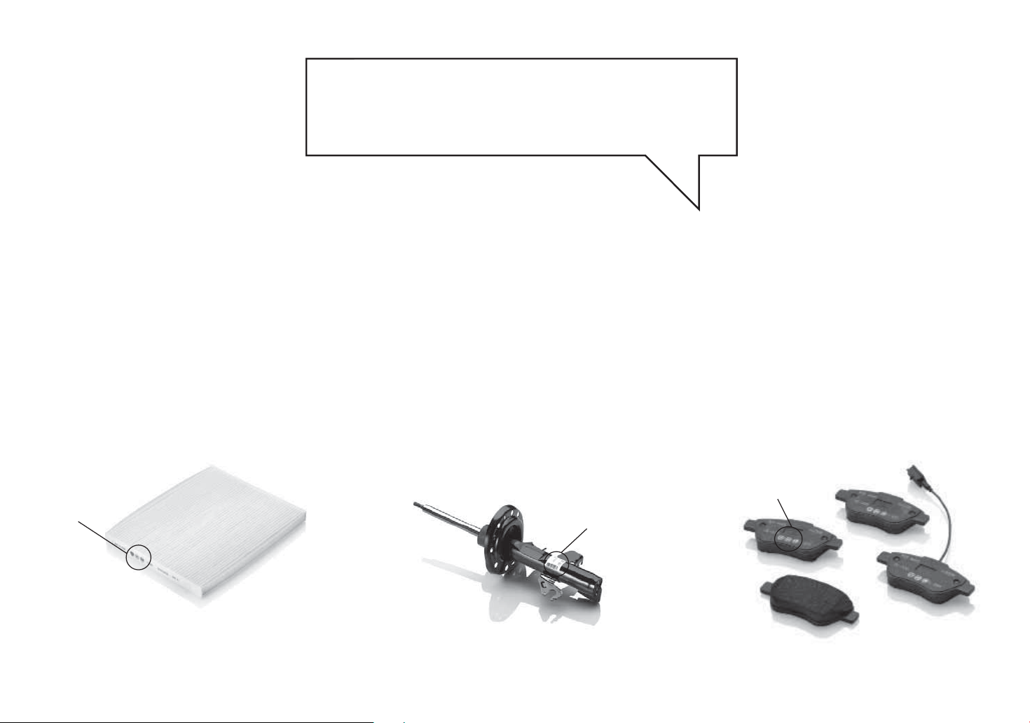
To recognise a Genuine Part, check that the component bears our brands, always clearly visible on Genuine Parts,
from the braking system to windscreen wipers, from shock absorbers to air cleaner.
All Genuine Parts undergo strict controls, both during design and manufacturing stages,
by specialists using vanguard materials, to test the component reliability.
This to guarantee performance and safety for you and your passengers on board, for a long time.
Always ask for and make sure a Genuine Part has been used.
Genuine
Genuine
Parts
Genuine
Parts
Parts
Air cleaner
Shock absorber
Brake pads
Page 5
Dear Customer,
We would like to congratulate and thank you for choosing Fiat.
We have written this handbook to help you get to know all the features of your car and use it in the best possible way.
You are recommended to read it right through before taking to the road for the first time.
It contains important information, advice and instructions for the use of the car which will help you get the very best out
of your Fiat. The handbook also provides a description of special features and tips as well as essential information for
correct care, maintenance, safe car driving and use and preservation of your Fiat over time.
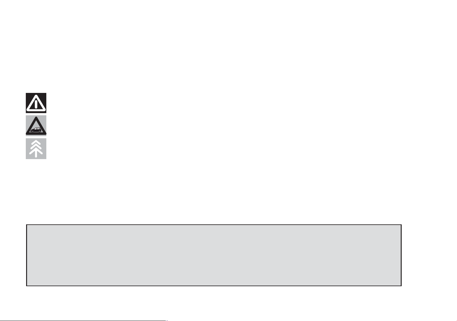
Carefully read the warnings and indications marked with the following symbols:
personal safety;
car safety;
environmental protection.
The enclosed Warranty Booklet lists the services that Fiat offers to its Customers:
❒ the Warranty Certificate with terms and conditions for maintaining its validity;
❒ the range of additional services available to Fiat Customers.
We are sure that these will help you get in touch with your new car and appreciate it and the care provided by the
people at Fiat.
Enjoy reading. Happy motoring!
This Owner Handbook describes all the versions of the Fiat Panda. As a
consequence, you should only consider the information which is related to the trim
level, engine and version that you have purchased. All data contained in this
publication are purely indicative. Fiat Group Automobiles can modify the
specifications of the vehicle model described in this publication at any time, for
technical or commercial reasons. For further information, contact a Fiat Dealership.
Page 6
ESSENTIAL INFORMATION!
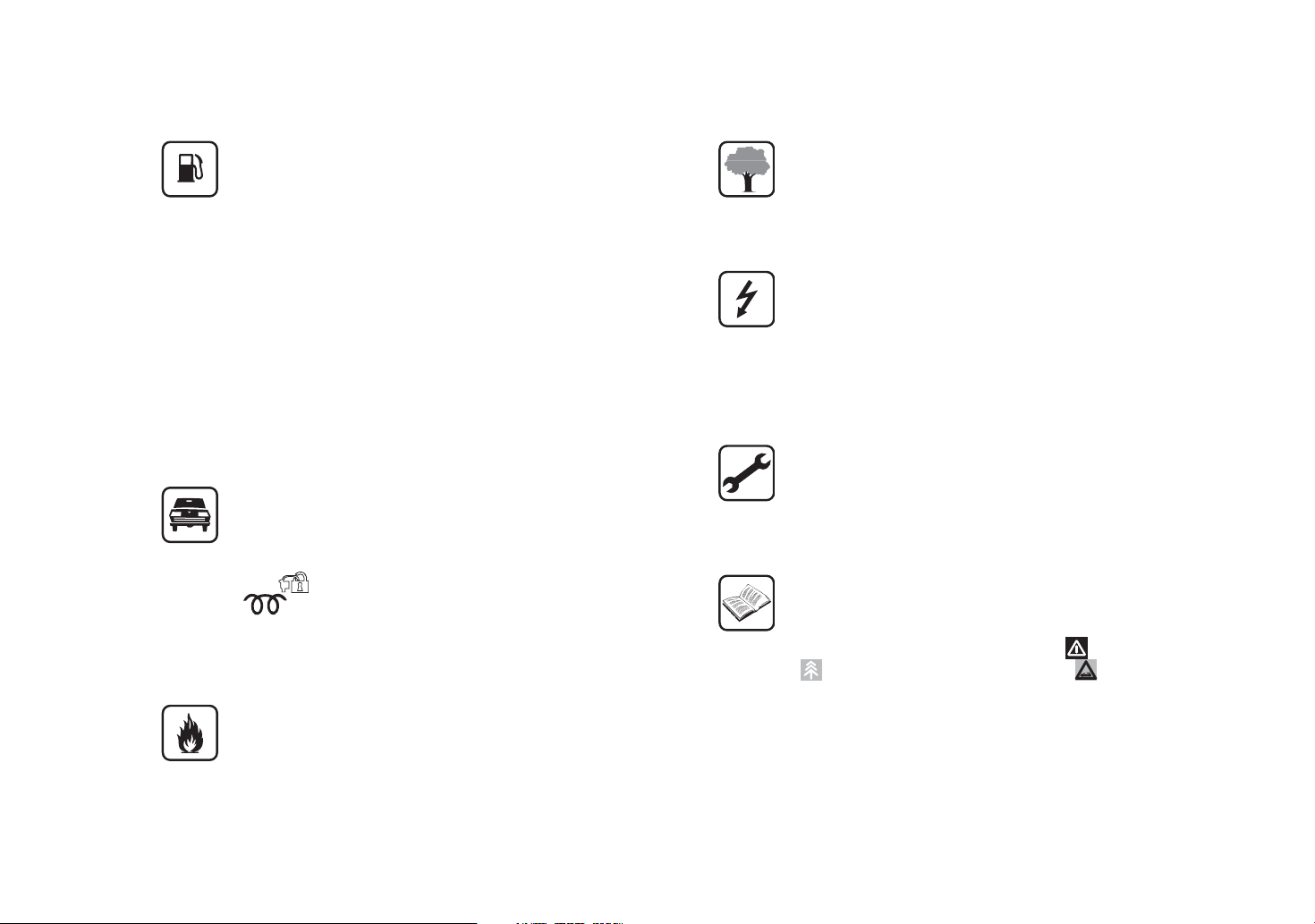
REFUELLING
Petrol engines: only refuel with unleaded petrol
with octane rating (RON) not less than 95 in
compliance with the European specification
EN228.
The use of petrol that does not conform to the
above-mentioned specification will cause the
EOBD warning light to switch on and the
irregular operation of the engine.
Diesel engines: only refuel with diesel for
motor vehicles in compliance with the European
specification EN590. The use of other products
or mixtures may damage the engine beyond
repair and consequently invalidate the warranty.
STARTING THE ENGINE
Make sure that the handbrake is engaged; place
the gear lever in neutral. Fully depress the clutch
pedal, without pressing the accelerator, then
turn the ignition key to MAR-ON and wait for
the
ignition key to AVV and release it as soon as
the engine starts.
PARKING ON FLAMMABLE MATERIAL
warning light to switch off (and
warning light for diesel versions); turn the
RESPECTING THE ENVIRONMENT
The car is fitted with a system that allows
continuous diagnosis of the components related
to emissions to ensure increased respect for
the environment.
ELECTRICAL ACCESSORIES
If, after buying the car, you decide to add
electrical accessories (with the risk of gradually
draining the battery), contact a Fiat Dealership.
They will calculate the overall electrical
requirement and check that the car’s electrical
system can support the required load.
SCHEDULED SERVICING
Correct maintenance of the car is essential for
ensuring that it maintains its performance and its
safety features, its environmental friendliness
and low running costs for a long time to come.
THE OWNER MANUAL CONTAINS…
… important information, advice and warnings
for correct use, driving safety and maintenance of
your car over time. Special attention must be
paid to the symbols provided (personal safety)
(environmental protection) (car integrity).
The catalytic converter develops high
temperatures during operation. Do not park the
car on grass, dry leaves, pine needles or other
flammable material: fire hazard.
Page 7
GETTING TO KNOW YOUR CAR
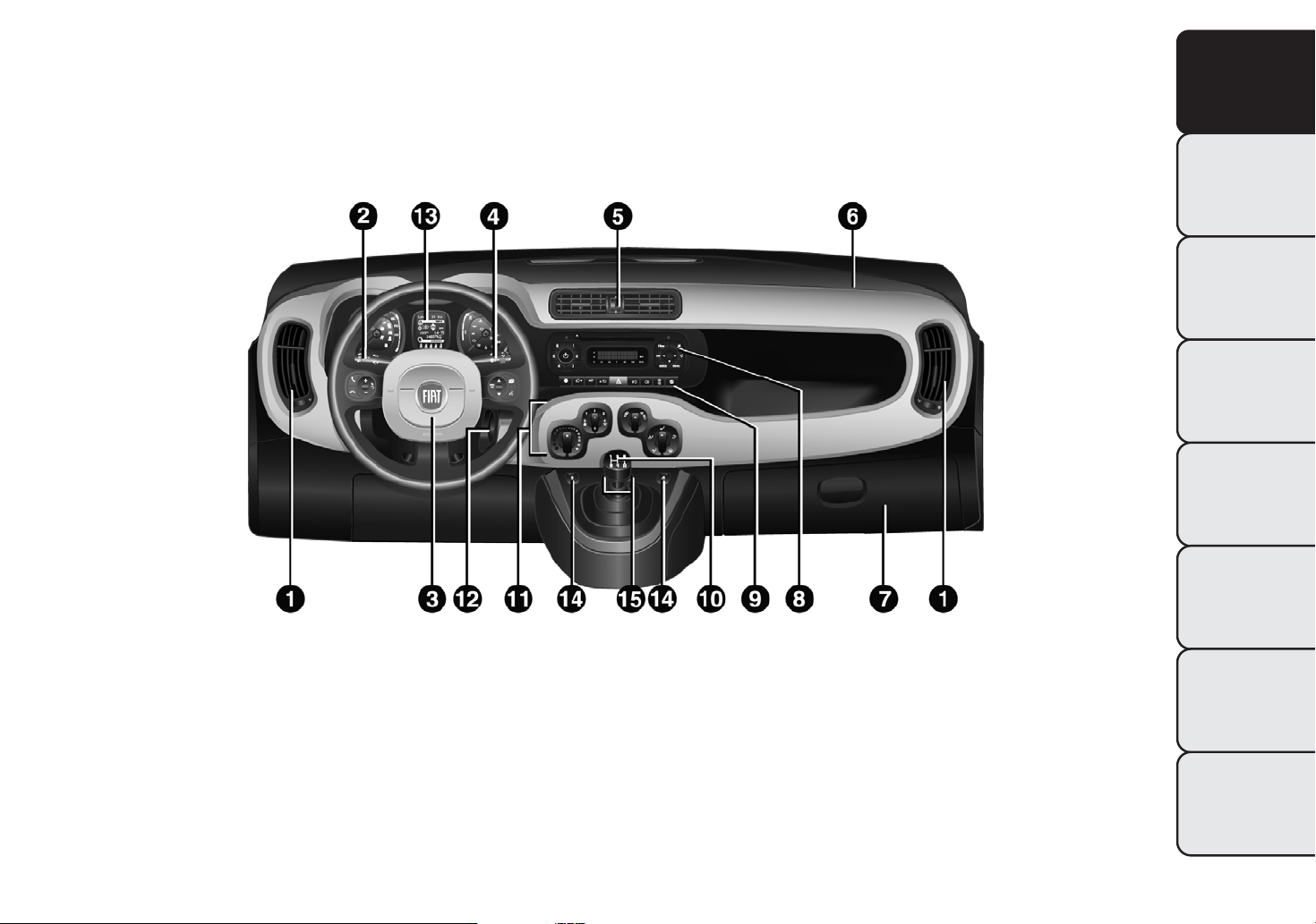
INSTRUMENT PANEL
The presence and position of the controls, instruments and indicators may vary according to the different
versions.
GETTING TO
KNOW YOUR CAR
SAFETY
STARTING AND
DRIVING
WARNING LIGHTS
AND MESSAGES
IN AN EMERGENCY
fig. 1
1. Adjustable and directable air diffusers 2. Exterior light control lever 3. Driver front airbag 4. Windscreen wiper/rear
window wiper/trip computer control lever 5. Adjustable and directable centre air diffusers 6. Passenger front airbag
7. Glove compartment (for versions/markets where provided) 8. Car radio (for versions/markets, where provided)
9. Control buttons 10. Gear lever 11. Heating/ventilation/climate control system controls 12. Ignition switch
13. Instrument panel 14. Electric front windows 15. ECO/ASR OFF buttons (for versions/markets, where provided)
F0W0092
SERVICING AND
MAINTENANCE
TECHNICAL
SPECIFICATIONS
INDEX
3
Page 8
GETTING TO
KNOW YOUR CAR
SAFETY
STARTING AND
DRIVING
WARNING LIGHTS
AND MESSAGES
IN AN EMERGENCY
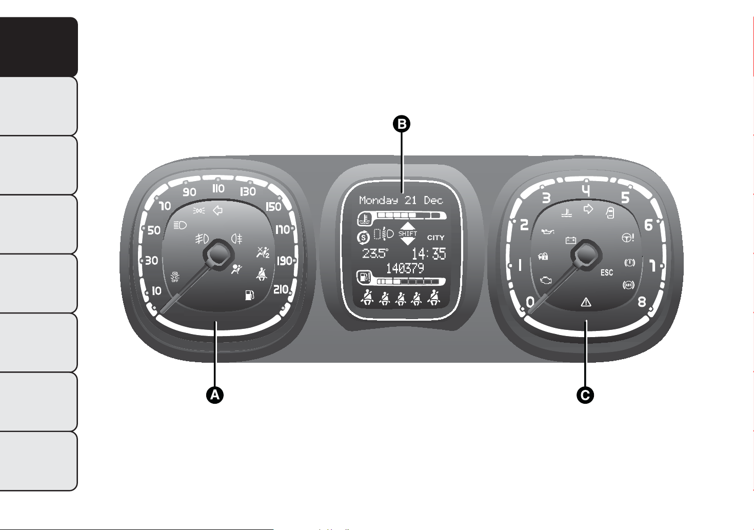
CONTROL PANEL AND
INSTRUMENTS
The instrument background colour and type may vary according to the version.
PETROLVERSIONS
C
TOT
kmi
SERVICING AND
MAINTENANCE
TECHNICAL
SPECIFICATIONS
fig. 2
A. Speedometer (speed indicator) B. Multifunction display C. Rev counter
INDEX
4
F0W0002
Page 9
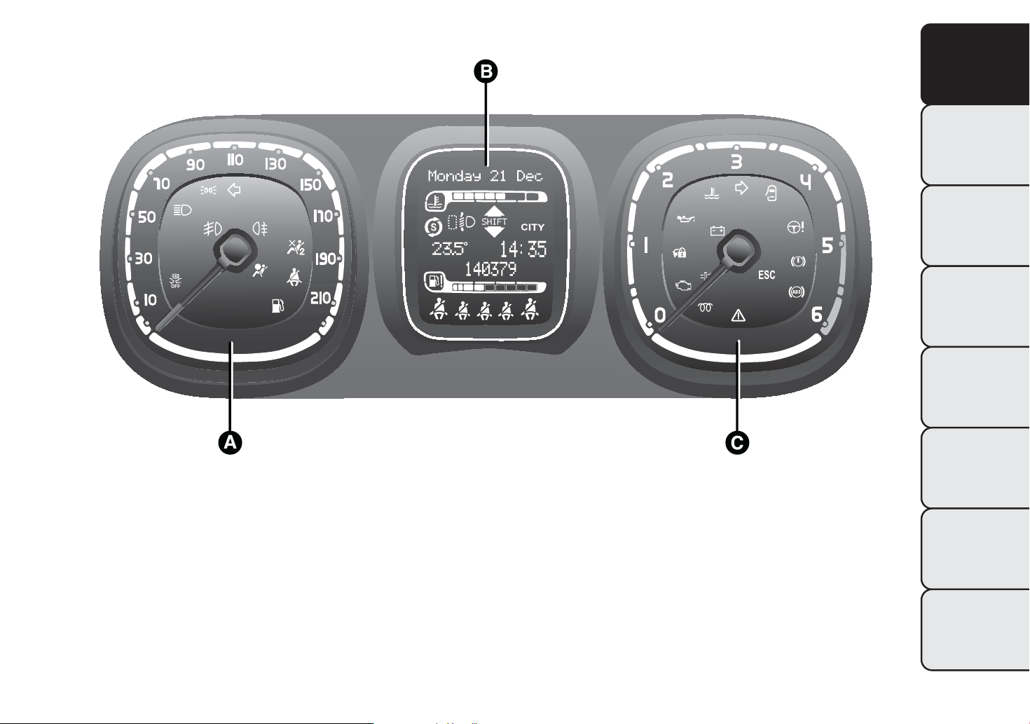
DIESEL VERSIONS
GETTING TO
KNOW YOUR CAR
SAFETY
STARTING AND
C
TOT
kmi
DRIVING
WARNING LIGHTS
AND MESSAGES
IN AN EMERGENCY
fig. 3
A. Speedometer (speed indicator) B. Multifunction display C. Rev counter
F0W0001
SERVICING AND
MAINTENANCE
TECHNICAL
SPECIFICATIONS
INDEX
5
Page 10
SPEEDOMETER (SPEED INDICATOR)
ENGINE COOLANT TEMPERATURE GAUGE
GETTING TO
KNOW YOUR CAR
SAFETY
STARTING AND
DRIVING
WARNING LIGHTS
AND MESSAGES
IN AN EMERGENCY
SERVICING AND
MAINTENANCE
Shows the car speed (speedometer).
REV COUNTER
This indicates the engine rpm.
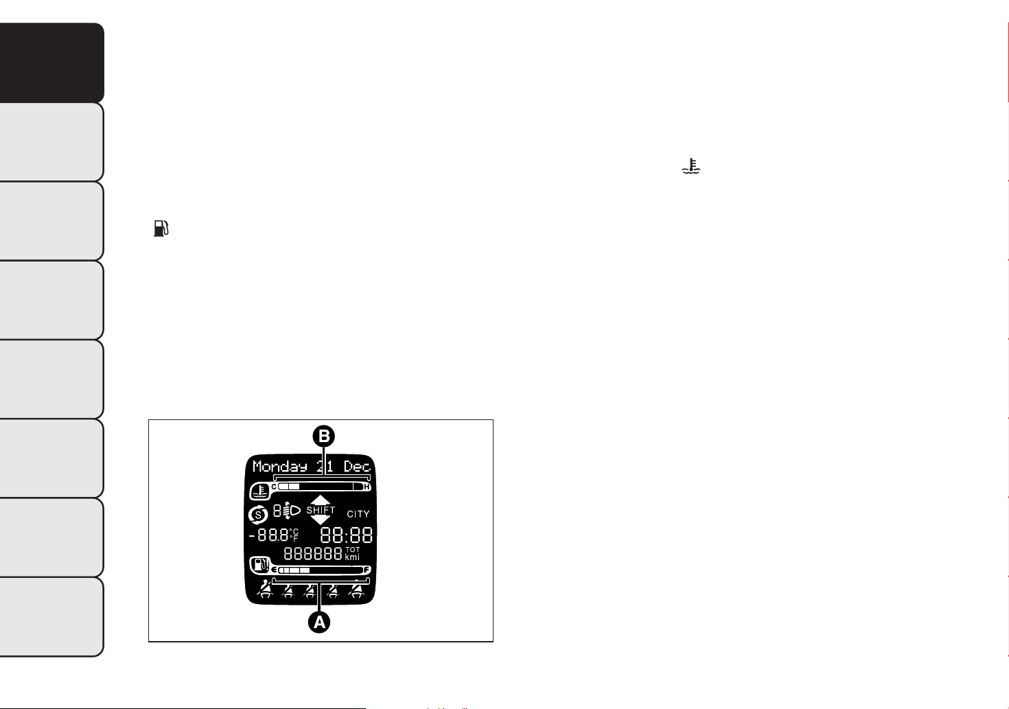
FUEL LEVEL GAUGE
The digital gauge A fig. 4 shows the amount of fuel in
the tank.
The
warning light fig. 4 switches on to indicate
that 5 to 7 litres of fuel are left in the tank.
Do not travel with the fuel tank almost empty:
possible gaps in fuel delivery could damage
the catalytic converter.
The digital indicator B fig. 4 shows the temperature
of the engine coolant and starts supplying indications
when the coolant temperature exceeds 50°C approx.
The first segment is always on to show that the
system is operating correctly.
The warning light
fig. 4 may switch on (together
with a message on the display) to indicate that
the coolant temperature is too high; in this case,
stop the engine and contact a Fiat Dealership.
TECHNICAL
SPECIFICATIONS
INDEX
6
fig. 4
F0W0026
Page 11
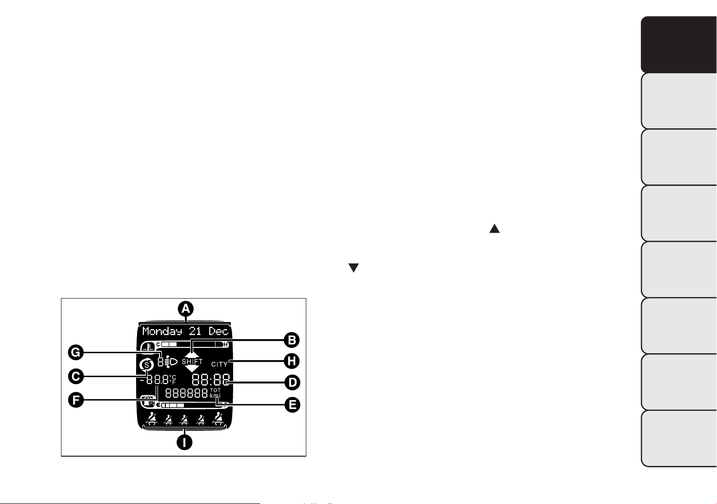
DISPLAY
With the ignition key removed, the display shows
three values for a few seconds when a front door is
opened: time, temperature and total milometer
reading (in km or miles).
"STANDARD" SCREEN
Outside temperature (for versions/markets, where
F
provided)
Headlight alignment position (only with dipped
G
headlights on)
Dualdrive electric power steering engagement
H
indication (CITY text)
Seat belt indicators
I
GETTING TO
KNOW YOUR CAR
SAFETY
The following information appears on the display
fig. 5:
Date
A
Gear Shift Indicator (for versions/markets, where
B
provided)
Start&Stop function indication (for versions/
C
markets where provided)
Time
D
Odometer (display of distance travelled in
E
kilometres/miles)
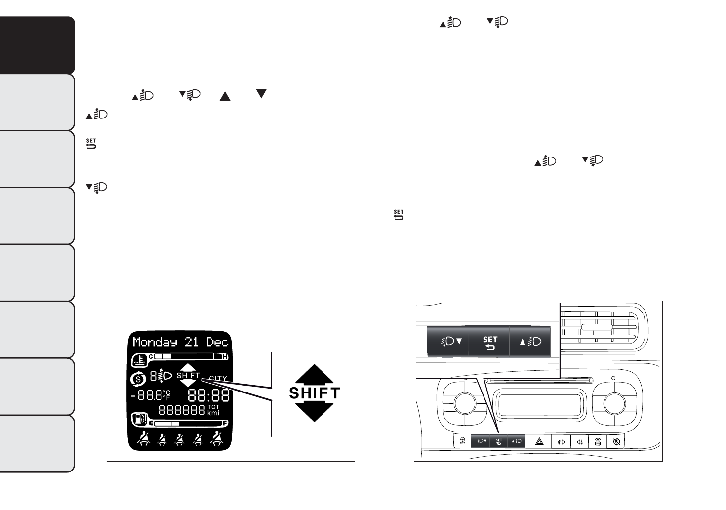
GEAR SHIFT INDICATOR
The GSI (Gear Shift Indicator) system advises the
driver to change gear through a specific indication on
the control panel. Through the GSI, the driver is
notified that changing gear will allow a reduction in
fuel consumption.
When the SHIFT UP icon (
SHIFT) fig. 5 is shown
on the display, the GSI is advising the driver to
engage a higher gear, while the SHIFT DOWN
(
SHIFT) icon advises the driver to engage a lower
gear.
The indication in the instrument panel remains on
until the driver changes gear or the driving
conditions return to a situation where changing gear
is not required to improve consumption.
STARTING AND
DRIVING
WARNING LIGHTS
AND MESSAGES
IN AN EMERGENCY
SERVICING AND
MAINTENANCE
TECHNICAL
SPECIFICATIONS
fig. 5
INDEX
F0W1008
7
Page 12
GETTING TO
KNOW YOUR CAR
SAFETY
STARTING AND
DRIVING
WARNING LIGHTS
AND MESSAGES
IN AN EMERGENCY
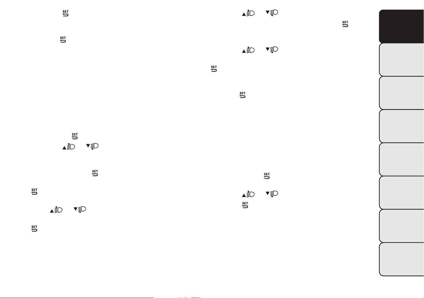
CONTROL BUTTONS
These can be used to scroll through the display
menu.
Note The symbol on the buttons depends on the
version:
and or and .
To scroll up through the screen and the related
options or to increase the displayed value.
Press briefly to access the menu and/or go to
next screen or to confirm the desired selection.
Hold down to go back to the standard screen.
To scroll down through the screen and the
related options or to decrease the displayed
value.
Buttons
and activate different functions
according to the following situations:
❒ within the menu, they allow you to scroll up and
down;
❒ during setting operations, they increase or
decrease values.
SETUP MENU
The menu comprises a series of options which can
be selected using buttons
and to access the
different selection and setting operations (Setup)
indicated below. Some options have a submenu. The
menu can be activated by briefly pressing the
button.
SERVICING AND
MAINTENANCE
TECHNICAL
SPECIFICATIONS
INDEX
fig. 6
8
F0W1010
fig. 7
F0W0042
Page 13

The menu includes the following items:
❒ MENU
❒ LIGHTING
❒ SPEED BEEP
❒ TRIP B ACTIVATION/DATA
❒ SET TIME
❒ press buttons
select the new setting;
❒ briefly press the
and to go back to the same main menu option
selected previously.
Selecting an option from the main menu with a
submenu:
or (with single presses) to
button to store the new setting
GETTING TO
KNOW YOUR CAR
SAFETY
❒ SET DATE
❒ SEE RADIO
❒ AUTOCLOSE
❒ MEASUREMENT UNIT
❒ LANGUAGE
❒ WARNING VOLUME
❒ SEAT BELT BUZZER (for versions/markets, where
provided)
❒ SERVICE
❒ AIRBAG/PASSENGER BAG (for versions/markets,
where provided)
❒ CITY BRAKE C./COLLISION MITIGATION (for
versions/markets, where provided)
❒ EXIT MENU
Selecting an option from the main menu without a
submenu:
❒ briefly press the
option to be set;
button to select the main menu
❒ a short press on the
submenu option;
❒ press buttons
scroll through all the submenu options;
❒ briefly press the
submenu option and to open the relevant set-up
menu;
❒ press buttons
select the new setting for this submenu option;
❒ Briefly press button
and at the same time go back to the previously
selected menu option.
button will display the first
or (with single presses) to
button to select the displayed
or (with single presses) to
to store the new setting
STARTING AND
DRIVING
WARNING LIGHTS
AND MESSAGES
IN AN EMERGENCY
SERVICING AND
MAINTENANCE
TECHNICAL
SPECIFICATIONS
INDEX
9
Page 14
GETTING TO
KNOW YOUR CAR
SAFETY
STARTING AND
DRIVING
WARNING LIGHTS
AND MESSAGES
IN AN EMERGENCY
SERVICING AND
MAINTENANCE
TECHNICAL
SPECIFICATIONS
MENU ITEMS
Menu
This option allows you to access the Setup Menu.
Press the
various Menu items. Hold down the
return to the standard screen.
Lighting (Interior car lighting adjustment)
(with side lights on only)
With the side lights on, this function is used to set
the brightness of the instrument panel, radio
controls and automatic climate control system
controls (for versions/markets, where provided) to 8
levels.
To adjust the brightness, proceed as follows:
press the
will flash on the display;
press the
level;
press the
screen or hold the button down to return to the
standard screen without storing.
or fig. 7 button to select the
button to
button briefly: the previously set level
or button to adjust the brightness
button briefly to return to the menu
Speed Beep (Speed limit)
This function is used to set the car speed limit (km/h
or mph); the driver is alerted when this limit is
exceeded.
To set the desired speed limit, proceed as follows:
❒ briefly press the
the text (Speed Beep);
❒ press the
activation (On) or deactivation (Off);
❒ if the function is on, press
desired speed limit and then press
Note Setting is possible between 30 and 200 km/h,
or 20 and 125 mph, according to the previously
set unit. See the "Measurement unit adjustment
(Measurement unit)" paragraph described below. The
setting will increase/decrease by 5 units each time
the
the setting rapidly. Complete the adjustment with
single presses of the button when you approach the
desired value.
❒ press the
screen or hold the button down to return to the
standard screen without storing.
To cancel the setting, proceed as follows:
❒ press the
display;
/ button is pressed. Hold down the
/ button to automatically increase/decrease
button briefly to return to the menu
button briefly: "On" will flash on the
button: the display will show
or button to select speed limit
or to select the
to confirm.
INDEX
10
Page 15

❒ press the button: "Off" will flash on the
display;
❒ press the
screen or hold the button down to return to the
standard screen without storing.
button briefly to return to the menu
❒ once you have selected the submenu to be
changed, press the
❒ when you select "Time", pressing
the "hours" flash on the display. press the
button to make the adjustment;
button briefly;
briefly makes
GETTING TO
KNOW YOUR CAR
or
Activation/Trip B data (Activating Trip B)
With this function it is possible to activate ("On") or
deactivate ("Off") the Trip B display (partial trip).
For more information see the "Trip computer"
paragraph.
For activation/deactivation, proceed as follows:
❒ press the
"On" or "Off" according to the previous setting;
❒ press the
adjustment;
❒ press the
screen or hold the button down to return to the
standard screen without storing.
Time adjustment (Clock adjustment)
This function allows the clock to be set through two
submenus: "Time" and "Format".
To carry out the adjustment, proceed as follows:
❒ press the
the two submenus "Time" and "Format";
button briefly to make the display flash
or button to make the
button briefly to return to the menu
button briefly: the display will show
❒ press the
the display. Press the
the adjustment;
❒ if you select the "Format" submenu, pressing the
button briefly makes the display mode flash on
the display. Press the
"12h" or "24h" mode. When you have carried
out the desired adjustment, press the
briefly to return to the submenu screen or hold
the button down to return to the main menu
screen without storing.
Hold down the
standard screen or to the main menu according to
where you are in the menu.
IMPORTANT The setting will increase or decrease
by one unit each time the
pressed. Holding the button down causes an
automatic rapid increase/decrease. Complete the
adjustment with single presses of the button when
you approach the desired value.
button briefly: the "minutes" flash on
or button to make
or button to select
button
button again to return to the
or button is
SAFETY
STARTING AND
DRIVING
WARNING LIGHTS
AND MESSAGES
IN AN EMERGENCY
SERVICING AND
MAINTENANCE
TECHNICAL
SPECIFICATIONS
❒ press the
the two submenus;
or button to switch between
INDEX
11
Page 16
GETTING TO
KNOW YOUR CAR
SAFETY
STARTING AND
DRIVING
WARNING LIGHTS
AND MESSAGES
IN AN EMERGENCY
SERVICING AND
MAINTENANCE
TECHNICAL
SPECIFICATIONS
Set date (Setting the date)
This function can be used to set the date (year month - day).
To carry out the adjustment, proceed as follows:
❒ briefly press the
the display;
❒ press the
adjustment;
❒ press the
on the display;
❒ press the
adjustment;
❒ briefly press the
the display;
❒ press the
adjustment;
❒ press the
screen or hold the button down to return to the
standard screen without storing.
IMPORTANT The setting will increase or decrease
by one unit each time the
pressed. Holding the button down causes an
automatic rapid increase/decrease. Complete the
adjustment with single presses of the button when
you approach the desired value.
button briefly: the "month" will flash
button briefly to return to the menu
button: the "year" will flash on
or button to make the
or button to make the
button: the "day" will flash on
or button to make the
or button is
❒ Radio: selected radio station frequency or RDS
message, automatic tuning activation or
AutoSTore;
❒ Audio CD, MP3 CDs: track number;
❒ CD Changer: CD number and track number.
To show the sound system information on the
display (On) or clear it (Off), proceed as follows:
❒ briefly press
display according to the previous setting;
❒ press the
❒ press the
screen or hold the button down to return to the
standard screen without storing.
Autoclose (Automatic central locking with car
in motion)
When activated (On), this function locks the doors
automatically when the vehicle speed exceeds 20
km/h.
To activate or deactivate this function, proceed as
follows:
❒ press the
"On" or "Off" according to the previous setting;
❒ press the
button, ON or OFF flashes on the
or button to select;
button briefly to return to the menu
button briefly to make the display flash
or button to select;
INDEX
12
See radio (audio information display)
With this function the display shows information
about the sound system.
Page 17
❒ press the button briefly to return to the
submenu screen or hold the button down
to return to the main menu screen without saving;
❒ hold the
standard screen or to the main menu according
to where you are in the menu.
Measurement unit (Setting the measurement
unit)
This function can be used to set the units through
three submenus: "Distances", "Consumption" and
"Temperature".
To set the desired unit of measurement, proceed as
follows:
❒ briefly press
❒ press the
the three submenus;
❒ once you have selected the submenu to be
changed, press the
❒ if you select "Distances", pressing the button
briefly makes the display show "km" or "mi"
depending on the previous setting;
❒ press
❒ if you select "Consumption", pressing button
briefly makes "km/l", "l/100km" or "mpg" appear
on the display depending on the previous setting;
If the set distance unit is "km", the display enables
setting of the fuel consumption unit (km/l or
l/100km). If the set distance unit is "mi", the display
shows the amount of fuel consumed in "mpg".
button down again to return to the
to display the three submenus;
or button to navigate through
button briefly;
or to select
❒ press the
❒ if you select “Temperature”, pressing the
briefly makes "°C" or "°F" appear on the display
depending on the previous setting;
❒ press the
❒ When you have made the adjustment, press the
button briefly to return to the submenu screen
or hold the button down to return to the main
menu screen without storing.
❒ hold the
standard screen or to the main menu according
to where you are in the menu.
Language (Language selection)
Display messages can be shown in different
languages: Italian, English, German, Portuguese,
Spanish, French, Dutch, Polish and Turkish.
To set the desired language, proceed as follows:
❒ briefly press the
"language" starts flashing on the display;
❒ press the
❒ press the
screen or hold the button down to return to the
standard screen without storing.
Warnings volume (Adjusting the failure/
warning acoustic signal volume)
With this function the volume of the buzzer which
accompanies the display of any failure/warning can be
adjusted to 8 levels.
or button to select;
button
or button to select;
button down again to return to the
button: the previously set
or button to select;
button briefly to return to the menu
GETTING TO
KNOW YOUR CAR
SAFETY
STARTING AND
DRIVING
WARNING LIGHTS
AND MESSAGES
IN AN EMERGENCY
SERVICING AND
MAINTENANCE
TECHNICAL
SPECIFICATIONS
INDEX
13
Page 18
GETTING TO
KNOW YOUR CAR
SAFETY
STARTING AND
DRIVING
WARNING LIGHTS
AND MESSAGES
IN AN EMERGENCY
SERVICING AND
MAINTENANCE
TECHNICAL
SPECIFICATIONS
INDEX
To set the desired volume, proceed as follows:
❒ press the
the previously set volume level;
❒ press the
❒ press the
screen or hold the button down to return to the
standard screen without storing.
Belt buzzer (Buzzer activation for SBR
indication) (for versions/markets, where provided)
This function can only be displayed after a Fiat
Dealership has deactivated the SBR system (see "SBR
system" in the "Safety" chapter).
Service (Scheduled servicing)
Using this function you can display information about
the mileage or daily intervals for car servicing. With
the Service function it is also possible to view the
interval (in kilometres or miles) before the next
engine oil change is due.
To consult this information, proceed as follows:
❒ briefly press the
show the service interval in kilometres (km) or
miles (mi) according to the previous setting (see
"Distance measurement units" paragraph);
❒ press the
screen or hold it down to return to the standard
screen.
button briefly, making the display flash
or button to select;
button briefly to return to the menu
button, which makes the display
button briefly to return to the menu
Note The “Scheduled Servicing Plan” requires the
car to be serviced every 30,000 km (or 18,000 miles)
for petrol versions and every 35,000 km (or 21,000
miles) for diesel versions. This message is displayed
automatically when the key is turned to MAR-ON,
starting at 2,000 km (or equivalent value in miles)
from when the next service is due and reappearing
every 200 km (or equivalent value in miles). Below
200 km servicing indications are more frequent. The
display will be in km or mi depending on the
measurement unit settings. When the next
scheduled service is approaching and the key is
turned to MAR, the word “Service” will appear on
the display, followed by the number of kilometres or
miles left before servicing is due. Go to a Fiat
Dealership, where the "Scheduled Servicing Plan"
operations will be performed and the message will
be reset.
Airbag/Passenger bag (Passenger side front
airbag and side bag (chest & pelvis protection
- for versions/markets, where provided)
activation/deactivation)
This function allows the passenger side airbag to be
activated/deactivated.
Proceed as follows:
❒ press the
pass: Off" (to deactivate) or "Bag pass: On" (to
activate) is displayed by pressing buttons
, press the button again;
❒ a confirmation message will appear on the display;
button and, after the message "Bag
and
14
Page 19
❒ by pressing the or buttons select "Yes" (to
confirm activation/deactivation) or "No" (to
cancel);
❒ press the
the selection is displayed and you return to the
menu screen. Hold down the button to return to
the standard screen without storing.
City Brake Control - "Collision Mitigation"
(for versions/markets, where provided)
This function is used to activate ("On") or
de-activate ("Off") the City Brake Control "Collision Mitigation" system.
To adjust, proceed as follows:
❒ press button
display, according to what has been previously set;
❒ a confirmation message will appear on the display;
❒ by pressing the
confirm activation/deactivation) or "No" (to
cancel);
❒ press the
the selection is displayed and you return to the
menu screen. Hold down the button to return to
the standard screen without storing.
When the system is deactivated the dedicated
warning light in the instrument panel switches on
(see chapter "Warning lights and Messages").
button briefly; a message confirming
briefly. "On" or "Off" flash on the
or buttons select "Yes" (to
button briefly; a message confirming
Exit Menu
The last function, which closes the cycle of settings
listed in the menu screen. Pressing the
briefly will return the display to the standard screen
without storing. Press the
the first menu item (Speed Beep).
button to return to
button
GETTING TO
KNOW YOUR CAR
SAFETY
STARTING AND
DRIVING
WARNING LIGHTS
AND MESSAGES
IN AN EMERGENCY
SERVICING AND
MAINTENANCE
TECHNICAL
SPECIFICATIONS
INDEX
15
Page 20

GETTING TO
KNOW YOUR CAR
TRIP COMPUTER
General information
Values displayed
Range
The Trip computer is used to display information on
car operation when the key is turned to MAR-ON.
SAFETY
STARTING AND
DRIVING
WARNING LIGHTS
AND MESSAGES
IN AN EMERGENCY
SERVICING AND
MAINTENANCE
TECHNICAL
SPECIFICATIONS
INDEX
Two separate trips, called “Trip A” and “Trip B”,
are provided to monitor the entire mission (journey)
in a reciprocally independent manner.
Both functions can be reset (reset - start of a new
journey).
“Trip A” is used to display the figures relating to:
❒ Outside temperature (for versions/markets where
❒ Range
❒ Distance covered
❒ Average consumption
❒ Instantaneous consumption
❒ Average speed
❒ Trip time (driving time).
“Trip B” is used to display the figures relating to:
❒ Distance travelled B
❒ Average consumption B
❒ Average speed B
❒ Trip time B (driving time).
Note The “Trip B” function may be disabled (see
“Activating Trip B”). The “Range” and “Instant
consumption" parameters cannot be reset.
provided)
This indicates the approximate distance which can be
travelled with the amount of fuel present in the
tank.“----”will appear on the display in the
following cases:
❒ range value lower than 50 km (or 30 mi)
❒ car parked with engine running for an extended
period.
IMPORTANT The range value variation can be
affected by several factors: driving style, type of route
(motorway, urban, mountain roads, etc.), conditions
of use (load, tyre pressures, etc.). Trip planning
must therefore take the above into account.
Distance covered
Shows the distance covered since the start of the
new journey.
Average consumption
Shows the approximate average fuel consumption
since the start of the new journey.
Instantaneous consumption
This indicates the fuel consumption. The value is
constantly updated. The display will show “----”if
the car is parked with the engine running.
16
Page 21
Average speed
New mission
This shows the average car speed as a function of the
overall time elapsed since the start of the new
journey.
Trip time
The time elapsed since the start of a new journey.
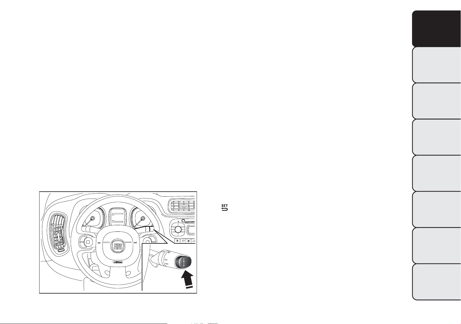
TRIP BUTTON
This is located on the right stalk. fig. 8 With the
ignition key turned to MAR, this button allows you
to view the previously described values as well as
reset them to begin a new journey:
❒ short press: display various values;
❒ long press: reset values and start a new journey.
This begins after a reset:
❒ “manual” resetting by the user, by pressing the
relevant button;
❒ “automatic” resetting, when the “Trip distance”
reaches 99999.9 km or when the “Travel time”
reaches 999:59 (999 hours and 59 minutes);
❒ after disconnection/reconnection of the battery.
IMPORTANT The reset operation when “Trip A” or
“Trip B” details are being displayed only resets the
values associated with the function displayed.
Start of journey procedure
With ignition key at MAR, press and hold down the
TRIP button for more than 2 seconds to reset.
Exiting the Trip Function
You can automatically exit the TRIP function once all
the values have been displayed or by holding the
button down for more than 1 second.
GETTING TO
KNOW YOUR CAR
SAFETY
STARTING AND
DRIVING
WARNING LIGHTS
AND MESSAGES
IN AN EMERGENCY
SERVICING AND
MAINTENANCE
fig. 8
2
1
0
F0W0079
TECHNICAL
SPECIFICATIONS
INDEX
17
Page 22

GETTING TO
KNOW YOUR CAR
SAFETY
STARTING AND
DRIVING
SYMBOLS
Some car components have coloured labels whose
symbols indicate precautions to be observed when
using this component. Under the bonnet there is
also a label that summarises all the symbols.
THE FIAT CODE SYSTEM
To further protect your car from theft, it has been
fitted with an engine immobilising system. It is
automatically activated when the ignition key is
removed.
Each key contains an electronic device which
modulates the signal emitted during ignition by an
antenna built into the ignition device. The signal
is the "password", different every time the car is
started, through which the control unit recognises
the key and enables starting.
WARNING LIGHTS
AND MESSAGES
IN AN EMERGENCY
SERVICING AND
MAINTENANCE
TECHNICAL
SPECIFICATIONS
INDEX
18
OPERATION
Each time the vehicle is started turning the ignition
key to MAR-ON, the Fiat CODE system control unit
sends an acknowledgement code to the engine
control unit to deactivate the immobiliser. The code
is sent only if the Fiat CODE system control unit
has acknowledged the code received from the key.
Each time the ignition key is turned to STOP, the Fiat
CODE system deactivates the functions of the
engine management control unit. If, during starting,
the code is not correctly recognised, the
light switches on in the instrument panel. In this
case, turn the key to STOP and then to MAR-ON; if
it is still locked, try again with the other keys that
come with the vehicle. Contact a Fiat Dealership
if you still cannot start the engine.
warning
Page 23
Warning light switching on while driving
If the
the system is running a self-diagnosis (for example
for a voltage drop). Should the fault persist, contact a
Fiat Dealership.
warning light switches on, this means that
THE KEYS
The electronic components inside the key
may be damaged if the key is subjected
to strong shocks. In order to ensure
complete efficiency of the electronic devices
inside the keys, they should never be exposed to
direct sunlight.
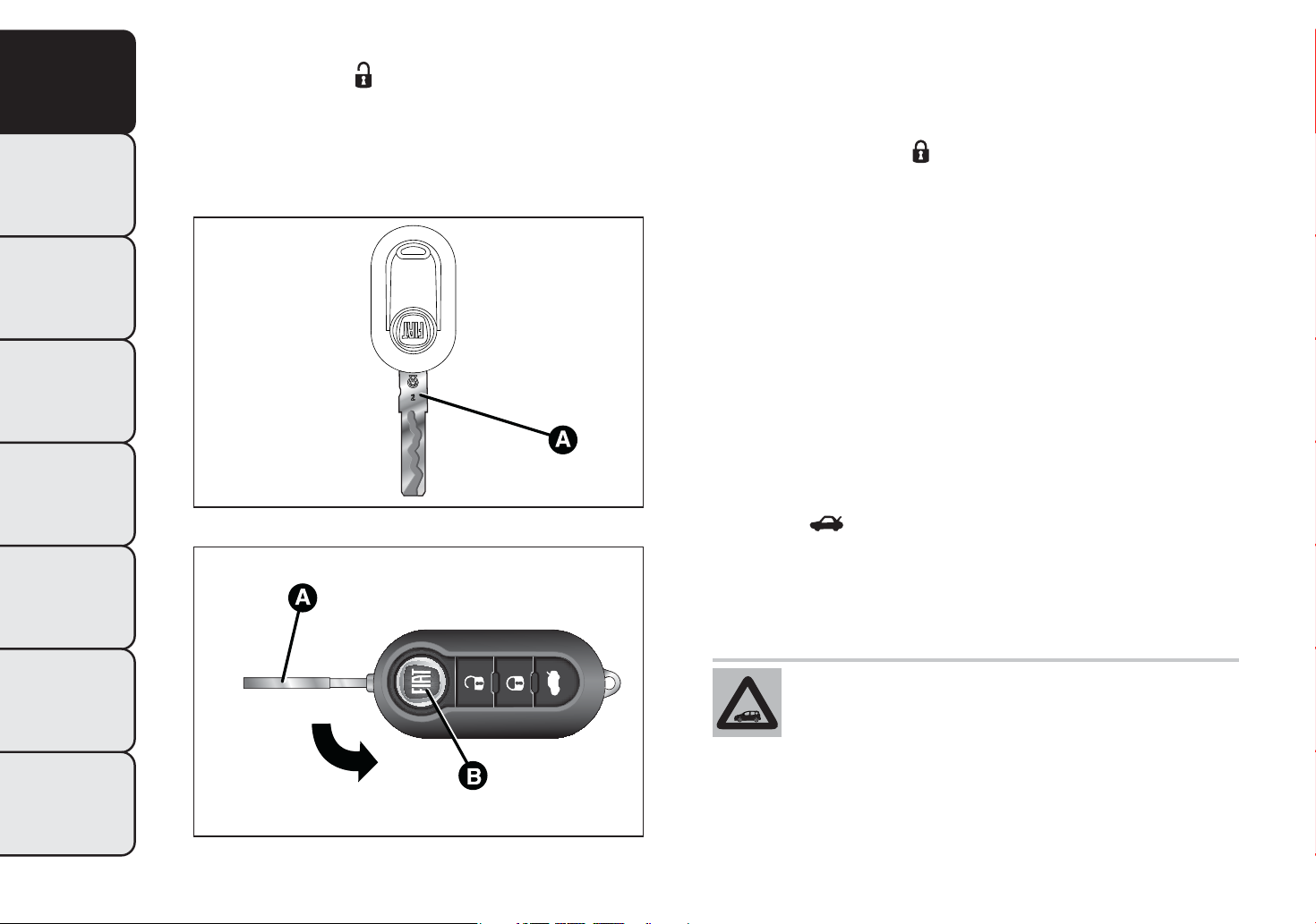
KEY WITHOUT REMOTE CONTROL
The metal insert A fig. 9 operates:
GETTING TO
KNOW YOUR CAR
SAFETY
STARTING AND
DRIVING
❒ the ignition switch;
❒ the driver side door and, for versions/markets
where provided, the passenger side door;
❒ the boot lock.
To request duplicates of the key, go to a Fiat
Dealership, taking an ID document and the car
ownership documents.
KEY WITH REMOTE CONTROL
(for versions/markets, where provided)
The metal insert A fig. 10 operates:
❒ the ignition switch;
❒ the driver side door and, for versions/markets
where provided, the passenger side door.
Press button B fig. 10 to open/close the metal insert.
WARNING LIGHTS
AND MESSAGES
IN AN EMERGENCY
SERVICING AND
MAINTENANCE
TECHNICAL
SPECIFICATIONS
INDEX
19
Page 24
GETTING TO
KNOW YOUR CAR
SAFETY
STARTING AND
DRIVING
WARNING LIGHTS
AND MESSAGES
Unlocking the doors and the tailgate
Briefly press button
: for unlocking of doors and
luggage compartment, timed switching-on of internal
roof lights and double flashing of direction indicators
(for versions/markets, where provided).
The doors are unlocked automatically if the fuel
cut-off system intervenes.
Locking the doors and the tailgate
Briefly press button
: for locking of doors and
luggage compartment, with switching-off of roof light
and single flashing of direction indicators (for
versions/markets, where provided).
If one or more doors are open, the doors will not be
locked. This is indicated by a rapid flashing of the
direction indicators (for versions/markets, where
provided). If the luggage compartment is open, the
doors will not be locked.
When a speed of over 20 km/h is reached, the doors
will be locked automatically if this specific function
was set.
IN AN EMERGENCY
SERVICING AND
MAINTENANCE
TECHNICAL
SPECIFICATIONS
INDEX
20
fig. 9
fig. 10
F0W0077
F0W0299
Opening the luggage compartment
Press the
button to open the luggage
compartment using the remote control.
The direction indicators will flash twice to indicate
that the luggage compartment has been opened.
The electronic components inside the key
may be damaged if the key is subjected
to strong shocks. In order to ensure
complete efficiency of the electronic devices
inside the key, it should never be exposed
to direct sunlight.
Page 25
Request for additional remote controls
The system can recognise up to 8 keys with
incorporated remote control. Should a new remote
control be necessary, go to a Fiat Dealership, taking
an ID document and the car ownership documents.
Used batteries must be disposed of, as
specified by law, in the special containers.
Otherwise take them to a Fiat Dealership,
which will deal with their disposal.
GETTING TO
KNOW YOUR CAR
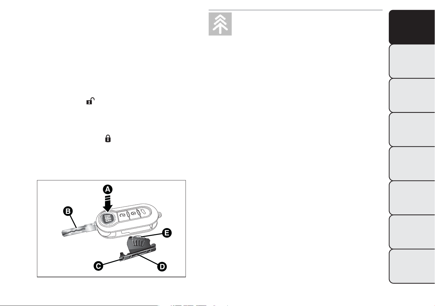
Changing battery - key with remote control
To replace the battery, proceed as follows:
❒ press button A fig. 11 and open the metal insert B;
❒ turn screw C to
using a fine bit screwdriver;
❒ take out the battery case D and replace the
battery E making sure that polarities are correct;
❒ refit the battery case D inside the key and lock it
by turning screw C to
.
SAFETY
STARTING AND
DRIVING
WARNING LIGHTS
AND MESSAGES
IN AN EMERGENCY
SERVICING AND
MAINTENANCE
TECHNICAL
SPECIFICATIONS
fig. 11
INDEX
F0W0189
21
Page 26
GETTING TO
KNOW YOUR CAR
SAFETY
STARTING AND
DRIVING
WARNING LIGHTS
AND MESSAGES
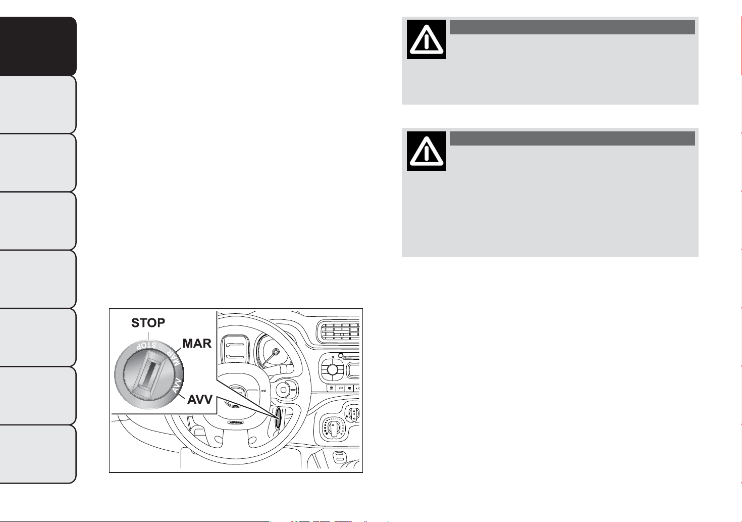
IGNITION DEVICE
The key can be turned to 3 different positionsfig. 12:
❒ STOP: engine off, key can be removed, steering
column locked. Some electrical devices (e.g. sound
system, central door locking system, etc.) can
operate;
❒ MAR-ON: driving position. All electrical devices
are enabled;
❒ AVV: engine start-up.
The ignition switch is fitted with a safety system that
requires the ignition key to be turned back to STOP
if the engine does not start, before the starting
operation can be repeated.
WARNING
If the ignition device has been tampered
with (e.g. an attempted theft), have it
checked over by a Fiat Dealership before driving
again.
WARNING
Always remove the key when you leave
your car to prevent someone from
accidentally operating the controls. Remember
to engage the handbrake. Engage 1
st
gear if
the car is parked uphill or reverse if the car is
parked downhill. Never leave children
unattended in the car.
IN AN EMERGENCY
SERVICING AND
MAINTENANCE
TECHNICAL
SPECIFICATIONS
INDEX
22
fig. 12
2
1
0
F0W0102
STEERING LOCK
Engagement: when the key is in position STOP,
remove the key and turn the steering wheel until it is
locked.
Disengagement: move the steering wheel slightly
as you turn the ignition key to MAR-ON.
Page 27
WARNING
It is absolutely forbidden to carry out
any after-market operation involving
steering system or steering column
modifications (e.g.: installation of anti-theft
device) that could badly affect performance and
safety, invalidate the warranty and also result
in non-compliance of the car with typeapproval requirements.
WARNING
SEATS
All adjustments must be made with the
car stationary.
If a side bag is fitted, it is dangerous to
use seat covers not available from
Lineaccessori Fiat.
WARNING
WARNING
GETTING TO
KNOW YOUR CAR
SAFETY
STARTING AND
DRIVING
Never remove the key while the car is
moving.The steering wheel will lock
as soon as it is turned.This holds true for cars
being towed as well.
FRONT SEATS
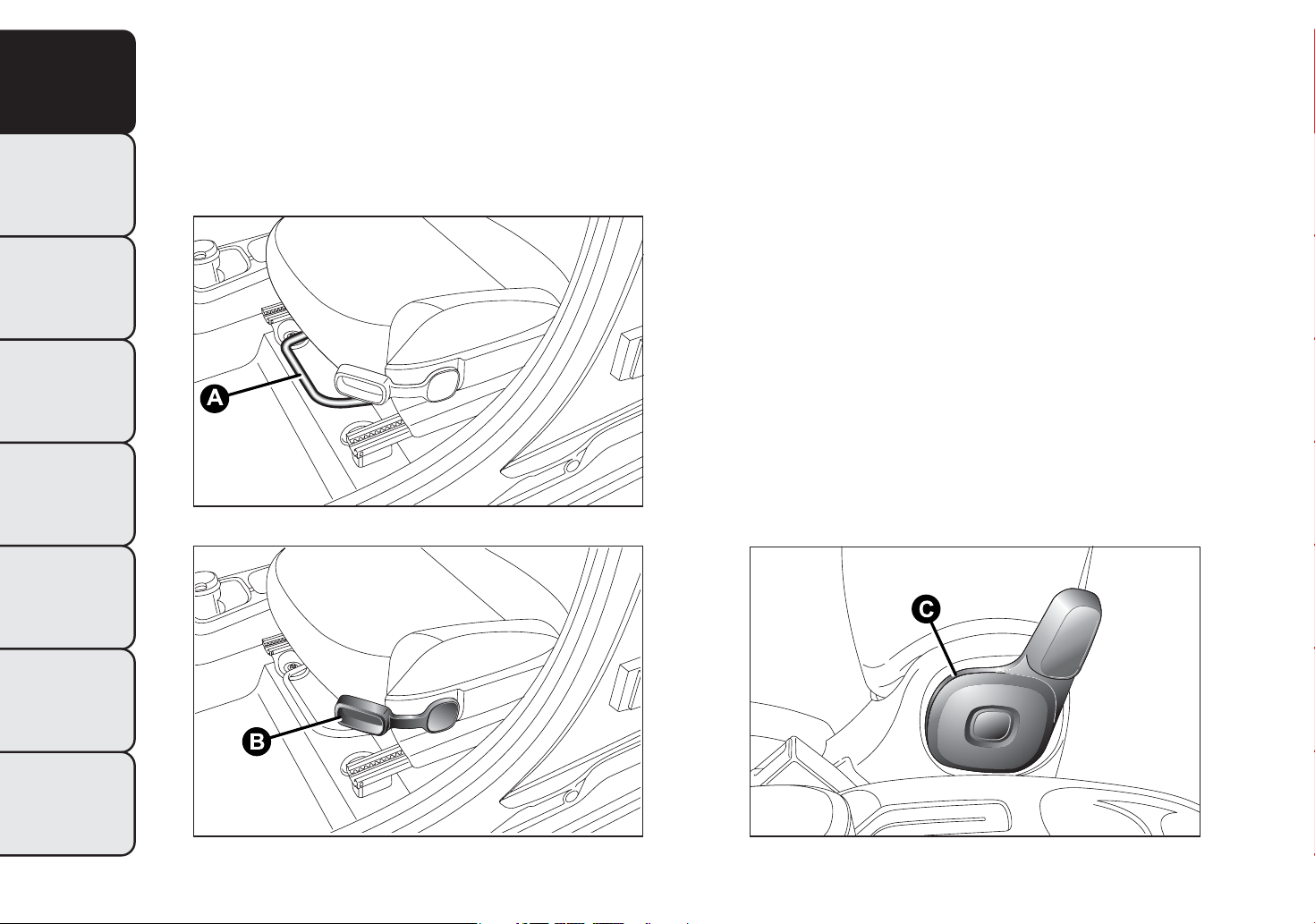
Lengthwise adjustment
Lift lever A fig. 13 and push the seat forwards or
backwards: in driving position your arms should rest
on the rim of the steering wheel.
WARNING
Once you have released the adjustment
lever, always check that the seat is
locked on the guides by trying to move it back
and forth. If the seat is not locked into place,
it may unexpectedly slide and cause the driver
to lose control of the car.
WARNING LIGHTS
AND MESSAGES
IN AN EMERGENCY
SERVICING AND
MAINTENANCE
TECHNICAL
SPECIFICATIONS
INDEX
23
Page 28
GETTING TO
KNOW YOUR CAR
SAFETY
STARTING AND
DRIVING
WARNING LIGHTS
AND MESSAGES
IN AN EMERGENCY
Height adjustment (for versions/markets, where
provided)
Adjust lever B fig. 14 upwards or downwards to
obtain the required height.
IMPORTANT Carry out the adjustment whilst seated
in the driver's seat.
fig. 13
F0W0062
Backrest angle adjustment
Operate lever C fig. 15 until the desired position is
reached, then release the lever.
Moving the fold-down passenger seat to table
position (for versions/markets, where provided)
Move the seat fully backwards by operating lever A
(see Lengthwise adjustment), lower the headrest (see
Headrest, downward adjustment), operate lever C,
fold the backrest down to the cushion and then
release lever C.
SERVICING AND
MAINTENANCE
TECHNICAL
SPECIFICATIONS
INDEX
fig. 14
24
F0W0063
fig. 15
F0W0064
Page 29
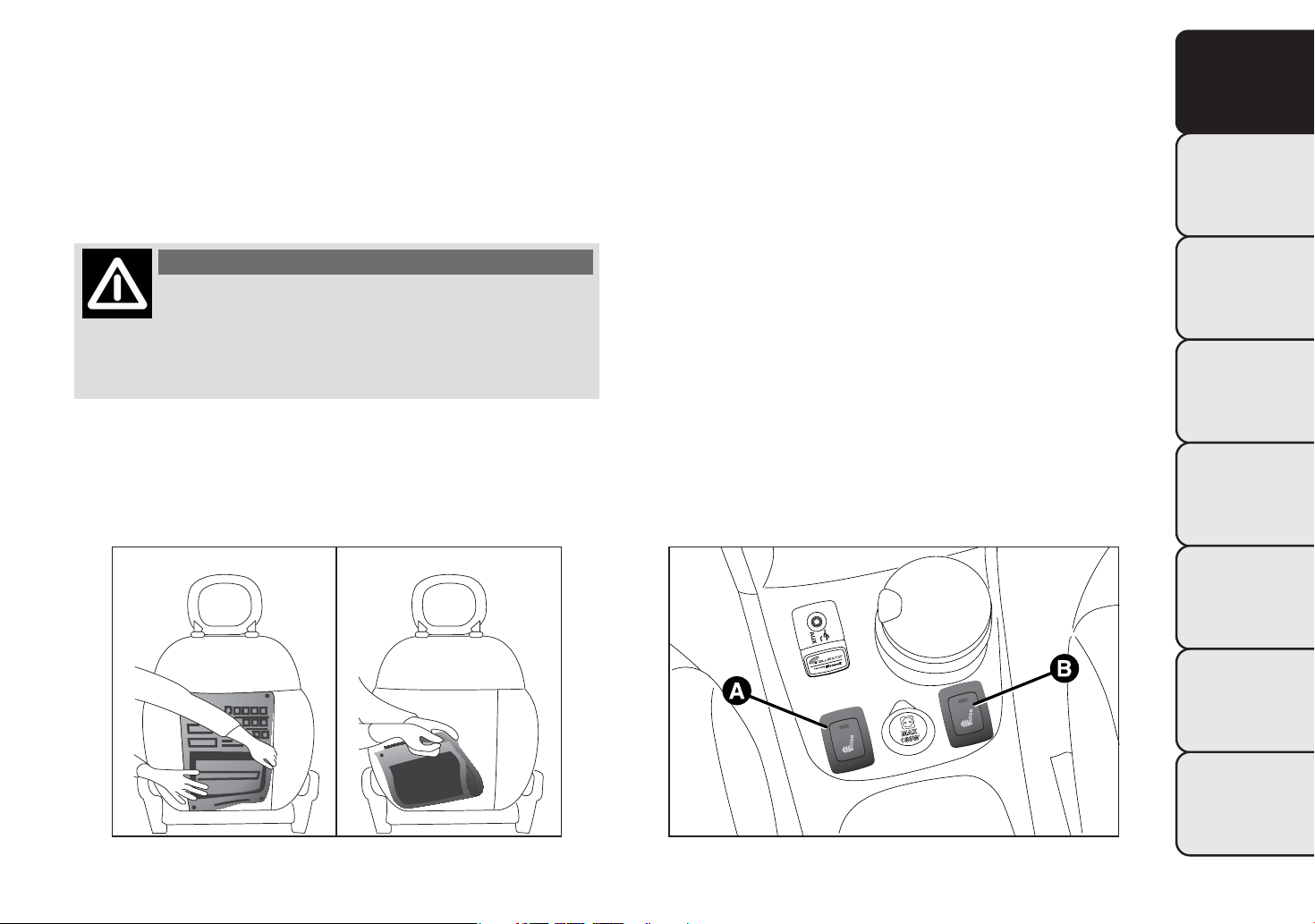
Document holder pocket (for versions/markets
where provided)
On some versions the multifunction pocket can be
removed from the seat backrest, using the two
pullers of the zips in the pocket bottom fig. 16.
Electric front seat heating (for versions/markets,
where provided)
To heat the cushion of the front seats, with the
ignition key in MAR-ON, press respectively button A
or B fig. 17.
GETTING TO
KNOW YOUR CAR
The removed pocket can be folded and closed with
the buttons at its ends.
WARNING
If passengers are seating in the rear
seats, remove all potentially dangerous
objects which may cause injuries in case of
accident.
To deactivate the function press the button again.
SAFETY
STARTING AND
DRIVING
WARNING LIGHTS
AND MESSAGES
IN AN EMERGENCY
SERVICING AND
MAINTENANCE
TECHNICAL
SPECIFICATIONS
fig. 16
F0W0302
fig. 17
INDEX
F0W0300
25
Page 30
GETTING TO
KNOW YOUR CAR
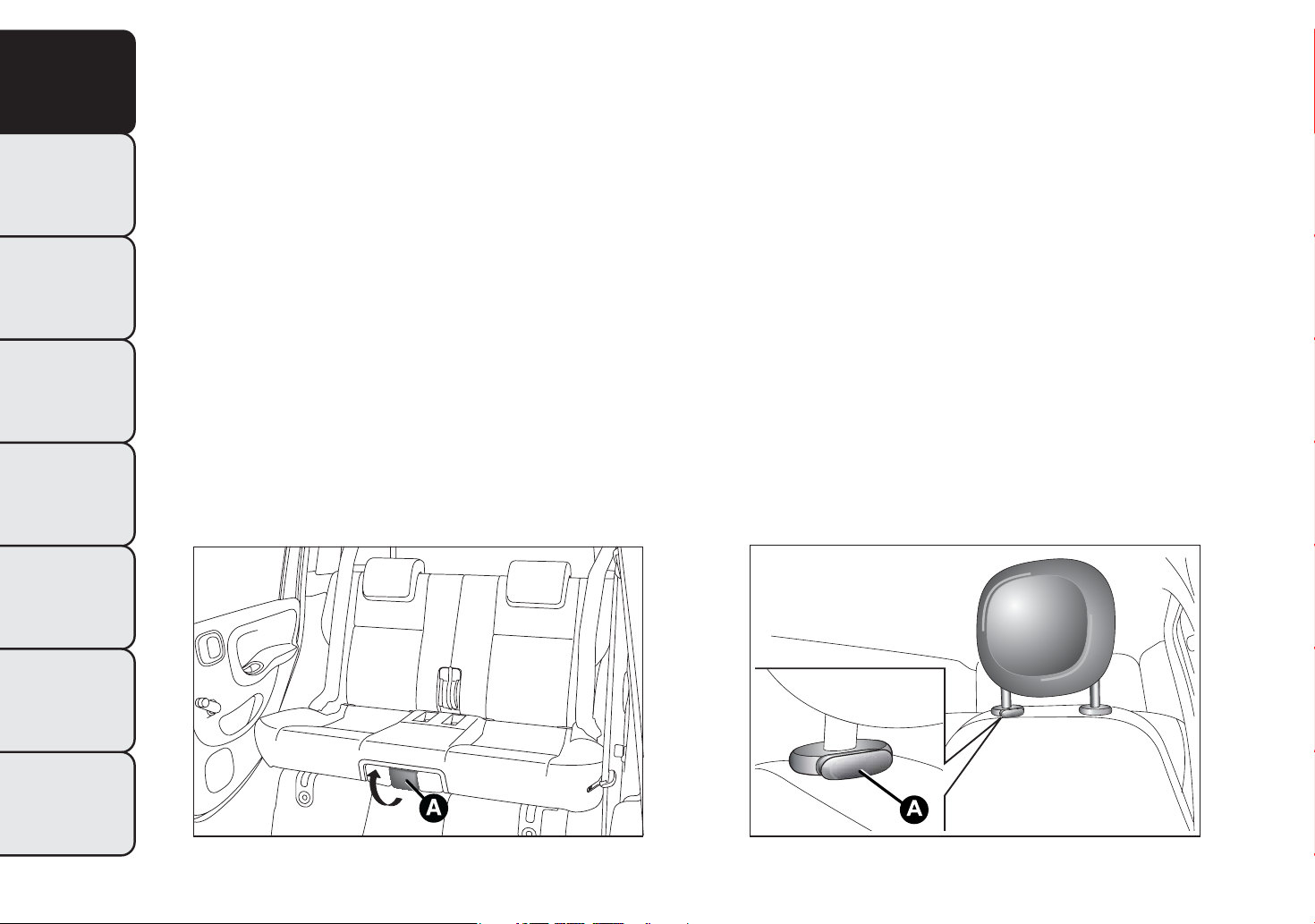
REAR SEATS
Sliding seats (for versions/markets, where
provided)
HEAD RESTRAINTS
FRONT
To bring the seat to the wished position, pull lever A
fig. 18 then adjust.
SAFETY
Folding seats (for versions/markets, where
provided)
To tilt rear seats, refer to chapter "Extending the
STARTING AND
boot".
DRIVING
WARNING LIGHTS
AND MESSAGES
IN AN EMERGENCY
SERVICING AND
MAINTENANCE
They are height-adjustable: to adjust them, operate
as follows.
Upwards adjustment: raise the head restraint
until it clicks into place.
Downwards adjustment: press button A fig. 19
and lower the head restraint.
"Anti-Whiplash" Device
The head restraints are equipped with an “AntiWhiplash” device, which reduces the distance
between head and head restraint in the event of a
rear impact, thus mitigating the "whiplash" effect.
TECHNICAL
SPECIFICATIONS
INDEX
26
fig. 18
F0W0301
fig. 19
F0W0061
Page 31

The head restraint may move when the backrest is
pressed by the occupant's torso or hand: this
behaviour is caused by the system and should not be
considered a malfunction.
Downwards adjustment: press button A fig. 20
and lower the head restraint.
Proceed as follows to remove the head restraints:
❒ raise the head restraints to their maximum height;
GETTING TO
KNOW YOUR CAR
WARNING
All adjustments must be made with the
car stationary. Head restraints must
be adjusted so that the head, rather than the
neck, rests on them. Only when they are
adjusted in this manner can they serve their
intended purpose.
WARNING
To make the best use of the head
restraint's protective action, adjust the
backrest so that you are sitting upright and
keep your head as close as possible to the head
restraint.
REAR
(for versions/markets, where provided)
❒ press buttons A and B fig. 20 at the side of the
two supports, then remove the head restraints
by pulling them upwards.
IMPORTANT If the rear seats are used, always set
the head restraints in the "completely raised"
position.
SAFETY
STARTING AND
DRIVING
WARNING LIGHTS
AND MESSAGES
IN AN EMERGENCY
SERVICING AND
MAINTENANCE
Depending on the version, the rear seats may be
fitted with two or three height-adjustable head
restraints.
Upwards adjustment: raise the head restraint
until it clicks into place.
fig. 20
TECHNICAL
SPECIFICATIONS
INDEX
F0W0201
27
Page 32

GETTING TO
KNOW YOUR CAR
SAFETY
STARTING AND
DRIVING
WARNING LIGHTS
AND MESSAGES
IN AN EMERGENCY
STEERING WHEEL
The steering wheel can be adjusted vertically.
To adjust, move lever A fig. 21 downwards to
position 1, then adjust the steering wheel to the
most suitable position and lock it in position by
moving lever A to position 2.
WARNING
All adjustments must be carried out only
with the vehicle stationary and engine
off.
WARNING
It is absolutely forbidden to carry out
any after-market operation involving
steering system or steering column
modifications (e.g. installation of anti-theft
device) that could badly affect performance and
safety, invalidate the warranty and also result
in the car not meeting type-approval
requirements.
SERVICING AND
MAINTENANCE
TECHNICAL
SPECIFICATIONS
INDEX
fig. 21
28
F0W0078
Page 33

REAR VIEW MIRRORS
REAR VIEW MIRROR
The mirror is fitted with a safety device that causes
its release in the event of a violent impact with
the passenger. Operate lever A fig. 22 to adjust the
mirror into two different positions: normal or
anti-glare.
Electrical adjustment (for versions/markets,
where provided)
The mirrors can be adjusted only if the ignition key is
in MAR position.
GETTING TO
KNOW YOUR CAR
SAFETY
DOOR MIRRORS
Manual adjustment
From the inside of the car, operate lever A fig. 23 to
adjust the mirror.
STARTING AND
DRIVING
WARNING LIGHTS
AND MESSAGES
IN AN EMERGENCY
SERVICING AND
MAINTENANCE
TECHNICAL
SPECIFICATIONS
fig. 22
F0W0054
fig. 23
INDEX
F0W0053
29
Page 34

To adjust proceed as follows:
Manual folding
GETTING TO
KNOW YOUR CAR
SAFETY
STARTING AND
DRIVING
WARNING LIGHTS
AND MESSAGES
IN AN EMERGENCY
SERVICING AND
MAINTENANCE
❒ select the desired mirror (left or right) using
switch A fig. 24 ;
❒ move switch A to position B and manipulate it to
adjust the left door mirror;
❒ move switch A to position D and manipulate it to
adjust the right door mirror.
Once you have finished the adjustment, return switch
A to intermediate locking position C.
IMPORTANT When the heated rear window is
activated, door mirror defrosting is activated (for
versions/markets, where provided).
If necessary, fold the mirrors by moving them from
position 1 (open) to position 2 (closed) fig. 25.
IMPORTANT When driving the mirrors must always
be in position 1 (open).
TECHNICAL
SPECIFICATIONS
INDEX
30
fig. 24
F0W0190
fig. 25
F0W0220
Page 35

CLIMATE CONTROL
SIDE AIR DIFFUSERS
CENTRAL AIR DIFFUSERS
GETTING TO
KNOW YOUR CAR
A fig. 26 - Adjustable and directable side air diffusers:
❒ use device B to adjust the diffuser to the desired
position;
❒ turn wheel C to enable/interrupt the air flow.
D - Fixed side air diffuser.
A fig. 27 - Adjustable and directable central air
diffusers:
❒ use device B to adjust the diffuser to the desired
position;
❒ turn wheel C to enable/interrupt the air flow.
SAFETY
STARTING AND
DRIVING
WARNING LIGHTS
AND MESSAGES
IN AN EMERGENCY
SERVICING AND
MAINTENANCE
fig. 26
F0W0103
fig. 27
TECHNICAL
SPECIFICATIONS
INDEX
F0W0104
31
Page 36

GETTING TO
KNOW YOUR CAR
SAFETY
STARTING AND
DRIVING
WARNING LIGHTS
AND MESSAGES
IN AN EMERGENCY
CLIMATIC COMFORT
DIFFUSERS
F0W0230
SERVICING AND
MAINTENANCE
fig. 28
TECHNICAL
SPECIFICATIONS
1. Fixed upper diffusers 2. Adjustable and directable and fixed side diffusers for side windows 3. Adjustable and directable
centre air diffusers 4. Passenger compartment footwell diffusers
INDEX
32
Page 37

HEATER/MANUAL CLIMATE
CONTROL
(for versions/markets, where provided)
CONTROLS
GETTING TO
KNOW YOUR CAR
SAFETY
STARTING AND
DRIVING
2
1
3
WARNING LIGHTS
0
4
AND MESSAGES
IN AN EMERGENCY
fig. 29
F0W0101
SERVICING AND
MAINTENANCE
TECHNICAL
SPECIFICATIONS
INDEX
33
Page 38

GETTING TO
KNOW YOUR CAR
SAFETY
STARTING AND
DRIVING
WARNING LIGHTS
AND MESSAGES
IN AN EMERGENCY
SERVICING AND
MAINTENANCE
TECHNICAL
SPECIFICATIONS
A Air temperature knob (red=hot/blue=cold)fig. 29
B Air recirculation knob fig. 29
internal air recirculation
air intake from outside
IMPORTANT It is advisable to switch the air
recirculation on whilst queuing or in tunnels, or
whilst driving on dusty roads, to prevent the
introduction of polluted air. However, it is better not
to use the function for long periods, particularly if
there are many people on board, to prevent the
windows from misting.
C Air distribution knob fig. 29
towards the body and the side windows
towards the body, the side windows and the feet
toward the feet mainly
towards the feet and the windscreen
towards the windscreen only
D Heated rear window, folding mirror/heated
windscreen (for versions/markets, where available)
activation/deactivation button fig. 29.
The LED on the button lights up to indicate
activation.
In order to maintain battery efficiency, the function is
automatically deactivated after about 20 minutes.
E Fan speed and climate control system activation/
deactivation knob fig. 29 (for versions/markets,
where provided). Press the knob to activate
the climate control system; the LED on the knob
switches on. This enables rapid cooling of the
passenger compartment. .
Note To stop the air flow from the vents turn the
knob to 0.
PASSENGER COMPARTMENT
VENTILATION
To ventilate the passenger compartment well,
proceed as follows:
❒ turn knob A fig. 29to the blue section;
❒ Turn selector B to external air recirculation
;
❒ turn knob C to
❒ turn knob E to the desired speed.
CLIMATE CONTROL (cooling - for
versions/markets, where provided)
For fast cooling of the passenger compartment,
proceed as follows:
❒ turn knob A fig. 29to the blue section;
❒ turn knob B to internal air recirculation
;
;
INDEX
34
❒ turn knob C to
;
Page 39

❒ press button E to turn the climate control system
on; the LED on the button will switch on;
❒ turn knob E to the desired speed.
IMPORTANT With a cold engine, you have to wait
for a few minutes to let the system fluid reach
optimum operating temperature.
GETTING TO
KNOW YOUR CAR
Cooling adjustment
❒ turn knob A fig. 29 to the right to increase the
temperature;
❒ turn knob B to external air recirculation
❒ turn knob E to the desired speed;
PASSENGER COMPARTMENT HEATING
For optimal heating of the passenger compartment,
proceed as follows:
❒ turn knob A fig. 29to the red section;
❒ turn knob C to the desired symbol;
❒ turn knob E to the desired speed.
FAST PASSENGER COMPARTMENT
HEATING
For fast heating of the passenger compartment,
proceed as follows:
❒ turn knob A fig. 29to the red section;
❒ Turn the knob to internal air recirculation
❒ turn knob C to
❒ turn knob E to 4
Then use the controls to maintain the required
comfort conditions and turn knob B to the outside
air intake symbol
;
(max. fan speed).
.
Fast windscreen and front side window
demisting/defrosting (MAX-DEF)
Proceed as follows:
;
❒ turn knob A to the red section;
❒ turn knob B to
❒ turn knob C to
❒ turn knob E to 4 (maximum fan speed).
IMPORTANT The climate control system is very
useful for speeding up demisting since it dehumidifies
the air. Adjust the controls as described above and
press knob E
on (the LED on the knob will switch on - for
versions/markets, where provided).
Heated rear window demisting/defrosting
Press the
activated, the button LED switches on.
For versions/markets where provided, press the
;
button to activate also demisting/defrosting
of windscreen (with engine running only) and door
mirrors (for versions/markets, where provided).
This function is timed and switches off automatically
after 4 minutes for the windscreen and 20 minutes
for the rear window and door mirrors. Press the
button
again to switch the function off in advance.
to switch the climate control system
button to activate: when this function is
;
;
SAFETY
STARTING AND
DRIVING
WARNING LIGHTS
AND MESSAGES
IN AN EMERGENCY
SERVICING AND
MAINTENANCE
TECHNICAL
SPECIFICATIONS
INDEX
35
Page 40

GETTING TO
KNOW YOUR CAR
SAFETY
To activate the heated windscreen again press the
button
❒ twice with LED on the button still on;
❒ once with LED on the button off.
IMPORTANT Do not apply stickers on the inside of
the rear window over the heating filaments to avoid
damage.
:
SYSTEM MAINTENANCE
In winter, the climate control system must be turned
on at least once a month for about 10 minutes.
Have the system inspected at a Fiat Dealership
before the summer.
STARTING AND
DRIVING
WARNING LIGHTS
AND MESSAGES
IN AN EMERGENCY
SERVICING AND
MAINTENANCE
TECHNICAL
SPECIFICATIONS
ADDITIONAL HEATER
(for versions/markets, where provided)
This allows the passenger compartment to be heated
more quickly in cold weather conditions. The heater
switches on automatically according to the
environmental conditions and with engine started
when the temperature of the engine coolant is low.
The additional heater turns off automatically after
the required comfort conditions are achieved.
The heater only operates if the outside temperature
and engine coolant temperature are low. The heater
will not activate if the battery voltage is too low.
INDEX
36
Page 41

AUTOMATIC CLIMATE CONTROL
(for versions/markets, where provided)
CONTROLS
GETTING TO
KNOW YOUR CAR
SAFETY
STARTING AND
DRIVING
WARNING LIGHTS
AND MESSAGES
IN AN EMERGENCY
fig. 30
F0W0129
SERVICING AND
MAINTENANCE
TECHNICAL
SPECIFICATIONS
INDEX
37
Page 42

GETTING TO
KNOW YOUR CAR
SAFETY
STARTING AND
DRIVING
WARNING LIGHTS
AND MESSAGES
IN AN EMERGENCY
SERVICING AND
MAINTENANCE
Buttons A - Manual air distribution selection
By pressing the buttons, one of the five possible
air flow distribution modes can be selected:
air flow to the windscreen and front side window
diffusers to demist or defrost them.
air flow to central and side dashboard vents to
ventilate the chest and the face during the hot
season.
towards the footwell diffusers. Due to the
natural tendency of heat to rise, this type of
distribution warms the passenger compartment
up as quickly as possible, providing an immediate
feeling of warmth.
distribution between footwell diffusers
+
(warmest air) and dashboard vents (coolest
air).
distribution between footwell diffusers and
+
windscreen/front side window vents. This
type of distribution achieves effective
heating of the passenger compartment and
prevents the windows from misting up.
Button B
- MAX-DEF function activation
❒ fan speed determined according to the coolant
temperature;
❒ air flow conveyed to the windscreen and front side
windows;
Button C
activation/deactivation
Pressing button C activates/deactivates climate
control:
❒ LED on button on: compressor on;
❒ LED on button off: compressor off.
When the compressor is off:
❒ the system will deactivate air recirculation to
prevent the windows from misting up;
❒ it is not possible to convey air to the passenger
compartment with a temperature below the
outside temperature (the displayed temperature
value will flash when the system cannot guarantee
the requested comfort conditions);
❒ the fan speed can be reset manually (with
compressor enabled, ventilation cannot go below a
bar shown on the display).
- Climate control compressor
TECHNICAL
SPECIFICATIONS
INDEX
38
When the
all the functions required for fast demisting/
defrosting:
❒ compressor on (if the weather conditions are
suitable);
❒ air recirculation off;
❒ maximum air temperature setting (HI);
button is pressed the system activates
Button D
activation/deactivation
It is advisable to switch the internal air recirculation
on whilst queuing or in tunnels to prevent the
introduction of polluted air.
At low temperatures or if the compressor is off, the
recirculation is forced to off to prevent misting.
- Internal air recirculation
Page 43

IMPORTANT It is inadvisable to use air recirculation
when the outside temperature is low, since the
windows could mist rapidly.
temperature, quantity and distribution of air entering
the passenger compartment and controls
compressor operation.
GETTING TO
KNOW YOUR CAR
Button E
Pressing the
With the system off, the climate control system
conditions are as follows:
❒ all LEDs are off;
❒ set temperature display is off;
❒ air recirculation is off;
❒ compressor is off;
❒ fan is off.
Button F
mirror/heated windscreen (for versions/
markets, where available) activation/
deactivation
Pressing the
button.
Buttons G/M
Use buttons G or M to increase or decrease the
air flow.
Button H (AUTO) - AUTO function activation
(automatic climate control operation)
When the AUTO button is pressed and the required
temperature is set, the system adjusts the
- Climate control on/off
button switches the system on/off.
- Heated rear window, folding
button switches on the LED on the
/ - Fan speed adjustment
Button I - Air temperature increase
When the button is pressed, the passenger
compartment air temperature increases.
Button L - Air temperature decrease
When the button is pressed, the passenger
compartment air temperature decreases.
DESCRIPTION
The automatically controlled parameters and
functions are:
❒ air temperature at the vents;
❒ air distribution at the vents;
❒ fan speed (continuous variation of the air flow);
❒ compressor activation (for cooling/dehumidifying
the air);
❒ air recirculation.
All functions may be changed manually. In other
words, you may select one or more functions and
change the parameters as required. Automatic
control of the manually changed functions will be
suspended: the system will only override your
settings for safety-related reasons (e.g. risk
of misting).
SAFETY
STARTING AND
DRIVING
WARNING LIGHTS
AND MESSAGES
IN AN EMERGENCY
SERVICING AND
MAINTENANCE
TECHNICAL
SPECIFICATIONS
INDEX
39
Page 44

GETTING TO
KNOW YOUR CAR
SAFETY
STARTING AND
DRIVING
WARNING LIGHTS
AND MESSAGES
IN AN EMERGENCY
SERVICING AND
MAINTENANCE
TECHNICAL
SPECIFICATIONS
INDEX
Manual selections always have higher priority over
automatic settings and are stored until the user
switches the system back to automatic control
except for cases in which the system intervenes for
particular safety-related reasons. You can adjust
one function manually without affecting the
automatic control of the others.
The amount of air introduced into the passenger
compartment is not affected by car speed; it is
regulated by the fan, which is controlled
electronically.
The temperature of the air supplied is always
controlled automatically, depending on the
temperature set in the driver’s display (except when
the system is off or in certain conditions when the
compressor is switched off).
The system allows the following to be set or adjusted
manually:
❒ air temperature;
❒ fan speed (continuous variation);
❒ air distribution with 5 positions;
❒ compressor enablement;
❒ rapid defrosting/demisting function;
❒ air recirculation;
❒ heated rear window, folding mirror/heated
windscreen (for versions/markets, where available);
❒ system deactivation.
SWITCHING ON THE CLIMATE CONTROL
SYSTEM
The system can be switched on in various ways; it is
however advisable to press the AUTO button and
set the desired temperature on the display.
The climate control system allows you to customise
the requested temperatures.
The climate control system compressor works only
with the engine running and with an outside
temperature of above 0°C.
AUTOMATIC CLIMATE CONTROL SYSTEM
OPERATION
Press the AUTO button; the system will
automatically adjust:
❒ the amount of air introduced into the passenger
compartment;
❒ the distribution of the air in the passenger
compartment;
cancelling all previous manual adjustments.
The LED on the AUTO button switches on during
automatic climate control operation.
During automatic operation it is still possible to
adjust the temperatures set and carry out one of the
following operations manually:
❒ fan speed adjustment;
❒ air distribution selection;
❒ internal air recirculation activation/deactivation;
40
❒ climate control compressor activation.
Page 45

WARNING
It is advisable not to use the air
recirculation function when the outside
temperature is low to prevent the windows from
rapidly misting up.
RAPID FRONT WINDOW
DEMISTING/DEFROSTING (MAX-DEF
function)
Press the
timed operation of all the functions required to
rapidly demist/defrost the windscreen and front side
windows (for versions/markets, where provided).
button to automatically activate the
GETTING TO
KNOW YOUR CAR
SAFETY
ADJUSTING THE FAN SPEED
Press the G fig. 30
decrease the fan speed
The possible speeds are displayed through a
progression of individual bars which comprise the
symbol:
❒ maximum fan speed = all bars lit
❒ minimum fan speed = half a bar lit.
The fan can be disabled (no bars lit) only if the
climate control compressor has been switched off by
pressing the
To restore automatic fan speed control after a
manual adjustment, press the AUTO button.
button.
or M button to increase/
.
The functions are:
❒ climate control compressor activation (with an
outside temperature of above 0°C);
❒ deactivation, if previously activated, of the internal
air recirculation;
❒ activation of heated rear window (LED on
button on) and door mirror heater coils (for
versions/markets, where provided);
❒ setting maximum air temperature;
❒ activation of air flow.
HEATED WINDSCREEN/HEATED REAR
WINDOW AND DOOR MIRROR
DEMISTING/DEFROSTING (for
versions/markets, where provided)
Press the
activated, the LED on the button switches on.
For versions/markets where provided, press the
button to activate also demisting/defrosting
of windscreen (with engine running only) and door
mirrors (for versions/markets, where provided).
button to activate: when this function is
STARTING AND
DRIVING
WARNING LIGHTS
AND MESSAGES
IN AN EMERGENCY
SERVICING AND
MAINTENANCE
TECHNICAL
SPECIFICATIONS
INDEX
41
Page 46

GETTING TO
KNOW YOUR CAR
SAFETY
STARTING AND
DRIVING
WARNING LIGHTS
AND MESSAGES
IN AN EMERGENCY
SERVICING AND
MAINTENANCE
TECHNICAL
SPECIFICATIONS
This function is timed and switches off automatically
after 4 minutes for the windscreen and 20 minutes
for the rear window and door mirrors.
Press the
in advance.
To activate the heated windscreen again press the
button
❒ twice with LED on the button still on;
❒ once with LED on the button off.
When the button
windscreen activates if it has not been activated
already by button
IMPORTANT Do not apply stickers on the inside of
the rear window over the heating filaments to avoid
damage.
IMPORTANT To draw in air from the outside, press
the
switches off.
INTERNAL AIR RECIRCULATION
ACTIVATION
Air recirculation is carried out according to two
possible operating modes:
❒ forced deactivation (air recirculation always
deactivated, air taken from the outside);
button again to switch the function off
:
is pressed, the heated
.
button. The LED next to the button
❒ LED on button on: internal air recirculation on;
❒ LED on button off: internal air recirculation off, air
drawn in from outside.
When the
system automatically activates internal air
recirculation. External air recirculation can always be
activated by pressing the button (LED off)
and vice versa.
Automatic recirculation operation is activated by
pressing the AUTO button.
IMPORTANT Internal air recirculation makes it
possible to reach the required heating or cooling
conditions more quickly depending on the mode
selected. It is not advisable to switch the air
recirculation on when it is rainy/cold to prevent the
windows from misting up, especially if the climate
control is not turned on. It is advisable to switch the
internal air recirculation on whilst queuing or in
tunnels, or whilst driving on dusty roads, to prevent
the introduction of polluted air. Do not use the
function for a long time, particularly if there are
several passengers on board, to prevent the windows
from misting up.
button is pressed, the climate control
INDEX
42
❒ forced activation (internal air circulation always
activated).
To activate internal air recirculation, press button D
.
Page 47

CLIMATE CONTROL COMPRESSOR
ACTIVATION/DEACTIVATION
Press the
compressor.
Compressor on: LED on
Compressor off:
❒ LED on
❒ internal air recirculation excluded;
With the climate control compressor switched off,
air cannot be introduced into the passenger
compartment that has a lower temperature than the
outside air; in this case the LED on the
will light up.
The deactivation of the climate control compressor
is memorised even after the engine has stopped.
To reactivate the climate control compressor, press
the
the other manual settings will be cancelled.
or AUTO button again: if you press AUTO,
button to switch on the climate control
button on.
button switches off;
button
+
+
IMPORTANT For the climate control system to
function, at least one of the buttons A must be
operated fig. 30. The system does not allow the
deactivation of all the buttons A.
IMPORTANT Push the
control system back on: in this way, all operating
conditions memorised before switching off are
restored.
To restore automatic control of the air distribution
after a manual selection, press the AUTO button.
Air flow distributed between footwell
diffusers and windscreen and front side
window defrosting/demisting diffusers. This
distribution setting allows the passenger
compartment to be warmed effectively and
prevents the windows from misting.
Air flow distribution between footwell
diffusers (hotter air) and centre/side
dashboard diffusers (cooler air).
button to turn the climate
GETTING TO
KNOW YOUR CAR
SAFETY
STARTING AND
DRIVING
WARNING LIGHTS
AND MESSAGES
IN AN EMERGENCY
AIR DISTRIBUTION SELECTION
Press one or more of buttons A fig. 30 to manually
select one of the possible air distribution settings for
the passenger compartment:
Air flow to the windscreen and front side
window diffusers to demist/defrost them.
Air flow to the footwell diffusers. This air
distribution allows the passenger compartment
to be warmed up quickly.
Air flow distribution to centre/side dashboard
diffusers (passenger's body).
SWITCHING OFF THE CLIMATE CONTROL
SYSTEM
Press the
The LEDS next to the
recirculation indication on the control panel switch
off.
SYSTEM MAINTENANCE
In winter, the climate control system must be turned
on at least once a month for about 10 minutes.
button.
symbol and internal air
SERVICING AND
MAINTENANCE
TECHNICAL
SPECIFICATIONS
INDEX
43
Page 48

GETTING TO
KNOW YOUR CAR
SAFETY
STARTING AND
DRIVING
WARNING LIGHTS
AND MESSAGES
IN AN EMERGENCY
SERVICING AND
MAINTENANCE
TECHNICAL
SPECIFICATIONS
INDEX
Have the system inspected at a Fiat Dealership
before the summer.
The system uses R134a coolant which
does not pollute the environment in the
event of accidental leakage. Never use
R12 fluid, which is not compatible with the
system components.
ADDITIONAL HEATER
(for versions/markets, where provided)
This allows the passenger compartment to be heated
more quickly in cold weather conditions. The heater
switches on automatically according to the
environmental conditions and with engine started
when the temperature of the engine coolant is low.
The additional heater turns off automatically after
the required comfort conditions are achieved.
The heater only operates if the outside temperature
and engine coolant temperature are low. The heater
will not activate if the battery voltage is too low.
Interaction of Automatic Climate Control
with START&STOP
(for versions/markets, where provided)
Automatic Climate Control
The automatic climate control manages the
Start&Stop function (engine off when the car speed
is zero) to guarantee adequate comfort inside the
passenger compartment.
In particular, when the weather is extremely hot or
cold, the Start&Stop function is deactivated until
adequate passenger compartment comfort is
ensured. During these transitory stages the engine is
not stopped, even if the car speed is zero.
When the Start&Stop function is active (engine off at
zero car speed), the climate control system will
request the reactivation of the engine if the inside
temperature conditions rapidly deteriorate (or if the
user requests maximum cooling – LO – or quick
demisting – MAX DEF).
With Start&Stop function active (engine off at zero
car speed), the air flow rate (if managed
automatically) is reduced in order to maintain the
passenger compartment comfort conditions for
as long as possible.
The climate control system control unit manages the
decreased comfort caused by stopping the engine,
and consequently the compressor, as far as possible.
The operation of the climate control system can in
any case be favoured by deactivating the Start&Stop
function using the dedicated button on the
dashboard.
NOTE In particularly severe climate conditions it is
recommended to limit the use of the Start&Stop
function to prevent the compressor from
continuously switching on and off, with consequent
rapid misting of the windows and accumulation of
humidity with unpleasant smells in the passenger
compartment.
44
Page 49

EXTERIOR LIGHTS
The left stalk operates most of the exterior lights.
The ignition key has to be in the MAR position
for the exterior lights to come on.
The instrument panel and the various dashboard
controls will come on with the exterior lights.
SIDE LIGHTS/DAYTIME RUNNING LIGHTS
(DRL)
"Daytime Running Lights"
(for versions/markets, where provided)
With the ignition key turned to MAR and ring nut A
fig. 31 turned to position O the daytime running
lights are automatically activated; the other lights and
interior lighting remain off.
WARNING
The daytime running lights are an
alternative to the dipped beam
headlights for driving during the daytime in
countries where it is compulsory to have lights
on during the day, and they are also permitted
in those countries where this not obligatory.
WARNING
Daytime running lights cannot replace
dipped beam headlights when driving at
night or through tunnels.The use of daytime
running lights is governed by the highway code
of the country in which you are driving. Comply
with legal requirements.
SIDE LIGHTS AND DIPPED BEAM
HEADLIGHTS
GETTING TO
KNOW YOUR CAR
SAFETY
STARTING AND
DRIVING
WARNING LIGHTS
AND MESSAGES
IN AN EMERGENCY
fig. 31
F0W0127
With the ignition key turned to MAR, turn the ring
nut A fig. 31 to
. If dipped beams are activated,
the daytime running lights go out and the side lights
and dipped headlights come on. The
warning
light will come on in the instrument panel.
When the ignition key is turned to STOP or
removed and the ring nut is turned from O to
, all
the side lights and number plate lights switch on.
The
warning light will come on in the
instrument panel.
SERVICING AND
MAINTENANCE
TECHNICAL
SPECIFICATIONS
INDEX
45
Page 50

PARKING LIGHTS
Lane change function
GETTING TO
KNOW YOUR CAR
SAFETY
STARTING AND
DRIVING
WARNING LIGHTS
AND MESSAGES
IN AN EMERGENCY
SERVICING AND
MAINTENANCE
TECHNICAL
SPECIFICATIONS
INDEX
These lights can only be turned on with ignition key
in STOP position or removed, by moving the ring nut
A first to position O and then to position
The warning light
panel.
MAIN BEAM HEADLIGHTS
To activate the main beam headlights, with ring nut at
, pull the stalk towards the steering wheel. The
warning light
When the stalk is pulled towards the steering wheel
again, the lights deactivate, the dipped headlights
reactivate and the
FLASHING
You can flash the headlights by pulling the stalk
towards the wheel (unstable position). The
warning light will come on in the instrument
panel.
DIRECTION INDICATORS
Bring the stalk to the (stable) position:
upwards: right direction indicator activation;
downwards: left direction indicator activation.
Warning light
panel. The indicators switch off automatically when
the steering wheel is straightened.
switches on in the instrument panel.
or will flash in the instrument
switches on on the instrument
warning light switches off.
.
If you wish to signal a lane change, place the left stalk
in the unstable position for less than half a second.
The direction indicator on the side selected will flash
five times and then switch off automatically.
“FOLLOW ME HOME” DEVICE
This allows the space in front of the car to be lit up
for a certain period of time.
Activation: with the ignition key on STOP or
removed, pull the stalk towards the steering wheel
within 2 minutes from when the engine is turned off.
At each single movement of the stalk, the lights
will remain on for an extra 30 seconds up to a
maximum of 210 seconds; then the lights are
switched off automatically.
Each time the stalk is operated, the
on the instrument panel switches on and the display
also shows a message and how long the function
will remain active.
The
first moved and stays on until the function is
automatically deactivated. Each time the stalk is
activated it increases the time that the lights remain
on.
Deactivation: keep the stalk pulled towards the
steering wheel for more than two seconds.
warning light switches on when the stalk is
warning light
46
Page 51

WINDOW CLEANING
The right stalk controls windscreen wiper/washer
and rear window wiper/washer operation.
WINDSCREEN WASHER/WIPER
It can be operated only with the ignition key turned
to MAR-ON.
The ring nut A fig. 32 can be moved to four different
positions:
windscreen wiper off.
intermittent operation.
continuous slow operation.
continuous fast operation.
Move the stalk upwards (unstable position) to limit
operation to the time for which the stalk is held
in this position.
When released, the stalk will return to its default
position and the wiper will be automatically stopped.
With the ring nut A fig. 32 in position
, the
windscreen wiper will automatically adapt operating
speed to the speed of the car.
With the windscreen wiper operational, if reverse
gear is engaged, the rear window wiper is
automatically activated.
Never use the windscreen wiper to remove
layers of snow or ice from the windscreen.
In such conditions, the windscreen wiper
may be subjected to excessive stress and the
overload cut-out, which prevents operation for a
few seconds, may intervene. If operation is not
restored (even after turning the key and
restarting the car engine), contact a Fiat
Dealership.
GETTING TO
KNOW YOUR CAR
SAFETY
STARTING AND
DRIVING
WARNING LIGHTS
AND MESSAGES
IN AN EMERGENCY
fig. 32
F0W0126
Do not operate the windscreen wiper with
the blades lifted from the windscreen.
"Smart washing" function
Pull the stalk towards the steering wheel (unstable
position) to activate the windscreen washer.
Keeping the stalk pulled for more than half a second,
with just one movement it is possible to operate
the washer jet and the wiper at the same time.
The wiper stops working three strokes after the
stalk is released.
SERVICING AND
MAINTENANCE
TECHNICAL
SPECIFICATIONS
INDEX
47
Page 52

GETTING TO
KNOW YOUR CAR
SAFETY
STARTING AND
DRIVING
WARNING LIGHTS
AND MESSAGES
A further stroke after approximately six seconds
completes the wiping cycle.
REAR WINDOW WASHER/WIPER
It can be operated only with the ignition key turned
to MAR-ON.
Activation
Turn ring nut B fig. 32 from position O to position
to operate the rear window wiper as follows:
❒ in intermittent mode when the windscreen wiper
is not operating;
❒ in synchronous mode (at half the speed of the
windscreen wiper) when the windscreen wiper
is operating;
❒ in continuous mode with reverse gear engaged and
the control active.
Do not use the rear window wiper to
removelayersofsnoworice.Inthese
conditions, the windscreen wiper may be
submitted to excessive effort resulting in the
motor protection cutting in and wiper operation
being inhibited for a few seconds. If operation
is not restored, contact a Fiat Dealership.
IN AN EMERGENCY
SERVICING AND
MAINTENANCE
TECHNICAL
SPECIFICATIONS
INDEX
With the windscreen wiper on and reverse gear
engaged, rear window wiping will be continuous.
Pushing the stalk towards the dashboard (unstable
position) the rear window washer jet will activate.
Keep the stalk pushed for more than half a second to
activate the rear window wiper as well. Releasing
the stalk will activate the smart washing function, as
described for the windscreen wiper.
The function stops when the stalk is released.
48
Page 53

ROOF LIGHTS
FRONT ROOF LIGHT
A switch positions:
❒ central position (position 1): lights C and D switch
on/off when the doors are opened/closed;
GETTING TO
KNOW YOUR CAR
Single-bulb roof light
The lens of roof light A fig. 33 has three positions:
❒ right side pressed: light always on
❒ left side pressed: light always off
❒ central position (neutral): the light switches on and
off when the doors are opened or closed.
Multi-bulb roof light (for versions/markets, where
provided)
The switch A fig. 34 switches on/off the roof light
bulbs.
❒ pressed to the left (position 0): lights C and D are
always switched off;
❒ pressed to the right (position 2): lights C and D
are always switched on.
The lights switch on/off gradually.
B switch positionsfig. 34:
❒ central position (position 1): lights C and D are
always switched off;
❒ pressed to the left (position 0): light C switches
on;
❒ pressed to the right (position 2): light D switches
on.
SAFETY
STARTING AND
DRIVING
WARNING LIGHTS
AND MESSAGES
IN AN EMERGENCY
SERVICING AND
MAINTENANCE
fig. 33
F0W0237
fig. 34
TECHNICAL
SPECIFICATIONS
INDEX
F0W0051
49
Page 54

GETTING TO
KNOW YOUR CAR
SAFETY
IMPORTANT Before getting out of the car, make
sure that both switches are in the central position:
when the doors are closed the lights will switch
off to avoid draining the battery. In any case, if the
switch is left in the on position, the roof light
switches off automatically about 15 minutes after the
engine has been switched off.
❒ when doors are locked (either with remote
control or with key on driver side door), the roof
light switches off.
❒ the courtesy lights are switched off in any case
after 15 minutes to preserve battery charge
Timing when getting out of the car
ROOF LIGHT TIMING
STARTING AND
DRIVING
WARNING LIGHTS
AND MESSAGES
IN AN EMERGENCY
SERVICING AND
MAINTENANCE
TECHNICAL
SPECIFICATIONS
On certain versions, to facilitate getting into/out of
the car, especially at night or in poorly-lit areas,
two timed modes have been provided.
Timing when getting into the car
The roof lights switch on according to the following
modes:
❒ for about 10 seconds when the doors are
❒ for about 3 minutes when one of the doors is
❒ for about 10 seconds when the doors are closed.
The timing is interrupted when the ignition key is
turned to MAR.
Three modes are provided for switching off:
❒ when all doors are closed, the 3-minute timer will
unlocked;
opened;
stop and a 10-second one will start. This timer will
stop when the key is turned to MAR;
After removing the key from the ignition switch, the
roof lights switch on as follows:
❒ if the ignition key is removed within 3 minutes
from the engine stopping, the roof lights switch on
for 10 seconds;
❒ for about 3 minutes when one of the doors is
opened;
❒ for about 10 seconds when one of the doors is
closed.
The timing stops automatically when the doors are
locked.
LUGGAGE COMPARTMENT ROOF LIGHT
(for versions/markets, where provided)
The roof light is located on the left side of the
luggage compartment. This switches on automatically
when the luggage compartment is opened and
switches off when it is closed. The light switches
on/off regardless of the ignition key position.
INDEX
50
Page 55

CONTROLS
HAZARD WARNING LIGHTS
Press button A fig. 35 to switch the lights on/off.
Warning lights
lit up when the lights are ON.
and in the instrument panel are
FOG LIGHTS
(for versions/markets, where provided)
Press button
fig. 36 to switch the lights on/off.
Press the button again to switch the lights off. With
lights on, the
warning light on the instrument
panel will switch on.
GETTING TO
KNOW YOUR CAR
SAFETY
IMPORTANT The use of hazard warning lights is
governed by the highway code of the country you are
driving in: comply with legal requirements.
Emergency braking
In the event of emergency braking the hazard
warning lights switch on automatically as well as
warning lights
and in the instrument panel. The
lights switch off automatically when emergency
braking ceases.
REAR FOG LIGHTS
Press the
fig. 36 button to switch the lights on/off.
The rear fog lights are only switched on with the
dipped headlights or front fog lights on. Press the
button again to switch the lights off, or switch off the
dipped headlights or the front fog lights (for
versions/markets, where provided).
With the lights on, warning light
in the instrument
panel switches on.
STARTING AND
DRIVING
WARNING LIGHTS
AND MESSAGES
IN AN EMERGENCY
SERVICING AND
MAINTENANCE
TECHNICAL
SPECIFICATIONS
fig. 35
F0W0191
fig. 36
INDEX
F0W0192
51
Page 56

GETTING TO
KNOW YOUR CAR
SAFETY
DUALDRIVE ELECTRIC POWER STEERING
(for versions/markets, where provided)
Press the CITY button fig. 37 to activate the function
(see paragraph "Dualdrive electric power steering"
in this section). When this function is active, the
word CITY on the instrument panel will light up. To
deactivate the function press the button again.
ECO button again to deactivate the function and
restore the normal driving setting.
FUEL CUT-OFF SYSTEM
This intervenes in the case of an impact causing:
❒ the interruption of the fuel supply with the engine
consequently cutting out;
ECO FUNCTION
STARTING AND
DRIVING
(for versions/markets, where provided)
Press the ECO button fig. 38 to activate the function.
When the ECO function is active, the car is set for
WARNING LIGHTS
AND MESSAGES
driving characterised by reduced fuel consumption.
When the function is active, the corresponding LED
on the button switches on.
This function stays in the memory and, when the
vehicle is started again, the system keeps the setting
IN AN EMERGENCY
it had before the engine was stopped. Press the
SERVICING AND
MAINTENANCE
TECHNICAL
SPECIFICATIONS
❒ the automatic unlocking of the doors;
❒ the automatic switching on of the interior lights
❒ the switching on of the hazard warning lights.
On some versions, the intervention of the system is
indicated by a message shown on the display.
IMPORTANT Carefully check the car for fuel leaks,
for instance in the engine compartment, under
the car or near the tank area. After an impact, turn
the ignition key to STOP to prevent the battery from
running down.
INDEX
52
fig. 37
F0W0082
fig. 38
F0W0039
Page 57

To restore the correct operation of the car, proceed
as follows:
❒ turn the ignition key to the MAR position;
INTERIOR FITTINGS
PASSENGER SIDE GLOVE COMPARTMENT
GETTING TO
KNOW YOUR CAR
❒ activate the right direction indicator;
❒ deactivate the right direction indicator;
❒ activate the left direction indicator;
❒ deactivate the left direction indicator;
❒ activate the right direction indicator;
❒ deactivate the right direction indicator;
❒ activate the left direction indicator;
❒ deactivate the left direction indicator;
❒ turn the ignition key to the STOP position.
WARNING
If, after an impact, you smell fuel or
notice leaks from the fuel system, do not
reactivate the system to avoid the risk of fire.
Operate handle A fig. 39 to open the compartment.
WARNING
Never travel with the glove
compartment open: it could injure the
passenger in the event of a crash.
SAFETY
STARTING AND
DRIVING
WARNING LIGHTS
AND MESSAGES
IN AN EMERGENCY
SERVICING AND
MAINTENANCE
fig. 39
TECHNICAL
SPECIFICATIONS
INDEX
F0W0057
53
Page 58

GETTING TO
KNOW YOUR CAR
SAFETY
STARTING AND
DRIVING
WARNING LIGHTS
AND MESSAGES
IN AN EMERGENCY
POWER SOCKET
It is located on the central tunnel fig. 40, near the
handbrake lever. It only operates with the ignition
key at MAR.
IMPORTANT Do not damage the socket by using
unsuitable adaptors.
With the "smoker's kit" optional, the cigar lighter is
fitted instead of the power socket.
To activate the cigar lighter, press the button with
the ignition key at MAR. After about 15 seconds the
button reverts automatically to its initial position
and the cigar lighter is ready for use.
WARNING
The cigar lighter becomes very hot.
Handle it carefully and make sure that
children do not touch it: risk of fire and/or
burns. Always check that the cigar lighter plug
has been released.
ASHTRAY
(for versions/markets, where provided)
The ashtray is a removable spring-loaded plastic
container that must be fitted into the right cup/can
holder on the central tunnel fig. 41.
IMPORTANT Do not use the ashtray as a waste
paper basket: it may catch fire in contact with
cigarette stubs.
SERVICING AND
MAINTENANCE
TECHNICAL
SPECIFICATIONS
INDEX
fig. 40
54
F0W0178
fig. 41
F0W0076
Page 59

IMPORTANT Do not damage the socket by using
unsuitable adaptors.
SUN VISORS
These are located at the sides of the rear-view
mirror. They can be adjusted forwards and sideways.
when specified, the back of the driver's and
passenger side visors houses two courtesy mirrors
(for versions/markets, where provided). To use
the mirror, open the sliding cover A fig. 42.
GLASSES HOLDER
(for versions/markets, where provided)
It is located on the left of the driver's side visor
fig. 43.
EXTINGUISHER
(for versions/markets, where provided)
It is located under the passenger side front seat or, in
some versions, at the right side of the luggage
compartment, inside a dedicated container.
GETTING TO
KNOW YOUR CAR
SAFETY
STARTING AND
DRIVING
WARNING LIGHTS
AND MESSAGES
IN AN EMERGENCY
fig. 42
F0W0055
fig. 43
SERVICING AND
MAINTENANCE
TECHNICAL
SPECIFICATIONS
INDEX
F0W0308
55
Page 60

GETTING TO
KNOW YOUR CAR
SAFETY
STARTING AND
DRIVING
WARNING LIGHTS
AND MESSAGES
SUN ROOF
(for versions/markets, where provided)
The large electric sun roof comprises two glass
panels; the front one is mobile and the rear one
fixed. These are equipped with two sun blinds (front
and rear) that can be moved manually. With the
sun roof closed, the blinds can be placed in any
position. To open the blinds, grip handle A fig. 44,
following the direction indicated by the arrow until
the desired position is reached. To close them, carry
out the procedure in reverse.
The sun roof can be operated only with the ignition
key turned to MAR. The controls B and C fig. 44
on the front roof light trim operate the roof
opening/closing functions.
Opening
Do not open the sunroof if there is snow
or ice on it: you may damage it. In
vehicles with sun roof no roof rack can be
fitted.
IN AN EMERGENCY
Press and hold down button C. The front glass panel
will move into the spoiler position.
After opening in spoiler position, press button C
SERVICING AND
MAINTENANCE
fig. 44 for more than half a second to bring the roof
automatically to fully open position. The automatic
roof movement can be stopped in any position by
pressing a button (B or C) again.
TECHNICAL
Closure
SPECIFICATIONS
Press button B from the fully open position fig. 44. If
the button is pressed for more than half a second,
the roof will automatically move to spoiler position.
INDEX
From the spoiler position, press button B fig. 44
again to reach the fully closed position.
56
fig. 44
F0W0152
Page 61

WARNING
When leaving the car, always remove the
key from the ignition to avoid the risk
of injury to those still inside the car due to
accidental operation of the sunroof. Improper
use of the roof may be dangerous. Before and
during operation, always check that no-one
is exposed to the risk of being injured by the
moving sunroof or by objects getting caught or
hitbyit.
ANTI-PINCH SAFETY DEVICE
For versions/markets where provided, the sun roof
has an anti-pinch safety system capable of detecting
the presence of an obstacle whilst the roof is closing;
if this happens, the system intervenes and the
movement of the glass is immediately reversed.
EMERGENCY OPERATION
❒ take the Allen key provided and located in the tool
box in the luggage compartment or, depending on
the version, inside the glove compartment;
❒ insert the key provided into the housing A fig. 45
and turn it clockwise to open the roof or
anticlockwise to close the roof.
INITIALISATION PROCEDURE
Following an automatic motion malfunction while
opening/closing or an emergency manoeuvre (see
description in the previous paragraph), the automatic
operation of the sun roof must be initialised again.
Proceed as follows:
❒ press button B fig. 44 in closing position;
❒ hold down button B: after approximately 10
seconds the roof moves jerkily to closing position.
Once the operation has ended (roof closed)
release button B;
GETTING TO
KNOW YOUR CAR
SAFETY
STARTING AND
DRIVING
WARNING LIGHTS
AND MESSAGES
IN AN EMERGENCY
If the electric device for moving the roof fails, the
sun roof can be moved manually proceeding as
described below:
❒ for manual activation remove the protective cap A
fig. 45 from its housing which is located on the
internal covering in front of the sun blind
fig. 45
SERVICING AND
MAINTENANCE
TECHNICAL
SPECIFICATIONS
INDEX
F0W0105
57
Page 62

GETTING TO
KNOW YOUR CAR
❒ turn the ignition key to STOP and keep it there for
10 seconds;
❒ turn the ignition key to the MAR position;
DOORS
LOCKING/UNLOCKING FROM OUTSIDE
❒ Press button B in closed position;
❒ hold down button B until the roof is completely
SAFETY
❒ press button B again within 3 seconds from the
STARTING AND
DRIVING
WARNING LIGHTS
AND MESSAGES
IN AN EMERGENCY
SERVICING AND
MAINTENANCE
❒ hold down button B: the roof will perform an
❒ keeping button B held down, wait until the roof is
closed: the initialisation procedure has ended;
conclusion of the initialisation procedure;
automatic opening and closing cycle: should this
not occur, repeat the operation from the
beginning;
completely closed.
To unlock
Turn the key in the lock fig. 46 to position 1 and pull
the handle upwards.
With central door locking (for versions/markets
where provided), the doors are unlocked
simultaneously when the key is turned.
With remote control (for versions/markets where
provided) press the
IMPORTANT Before opening a door, ensure that you
can do it in conditions of safety. Open the doors
only when the car is stationary.
IMPORTANT Open the doors only when the car is
stationary.
To lock
Rotate the key in the lock fig. 46 to position 2 with
fully closed door.
button to open the doors.
TECHNICAL
SPECIFICATIONS
INDEX
58
With central door locking (for versions/markets
where provided) all doors must be shut properly.
With remote control (for versions/markets where
provided) press the
If one of the doors is not shut properly, simultaneous
locking is disabled.
button to close the doors.
Page 63

IMPORTANT If one of the front doors is not fully
closed or in the event of system failure, central door
locking will not operate and, after 10/11 attempts
in quick succession, the system will be excluded for
about 30 seconds.
LOCKING/UNLOCKING FROM INSIDE
To unlock
To lock
Push the control lever A fig. 47 towards the door.
Operating the lever A on driver's side will lock
all doors. With mechanical locks, without central
locking, closing takes place by operating the
individual control levers.
IMPORTANT On the other doors, the lever will only
lock the door concerned.
GETTING TO
KNOW YOUR CAR
SAFETY
Pull the control lever A fig. 47.
With central door locking system (for versions/
markets, where provided), operating the lever A on
the driver's side will unlock all the doors. Lever A on
the other doors will only open the corresponding
door.
IMPORTANT The locked door condition is indicated
by the red printing B fig. 48.
STARTING AND
DRIVING
WARNING LIGHTS
AND MESSAGES
IN AN EMERGENCY
SERVICING AND
MAINTENANCE
TECHNICAL
SPECIFICATIONS
fig. 46
F0W0321
fig. 47
INDEX
F0W0306
59
Page 64

GETTING TO
KNOW YOUR CAR
SAFETY
STARTING AND
DRIVING
WARNING LIGHTS
AND MESSAGES
IN AN EMERGENCY
CHILD LOCK DEVICE
This system prevents the rear doors from being
opened from the inside.
Device A fig. 49 can only be engaged with the doors
open:
❒
position1-device engaged (door locked);
❒
position2-device not engaged (door may be
opened from the inside).
The device remains on even if the doors are
unlocked electrically.
IMPORTANT The rear doors cannot be opened
from the inside when the child lock device is
engaged.
SERVICING AND
MAINTENANCE
TECHNICAL
SPECIFICATIONS
INDEX
fig. 48
60
F0W0307
fig. 49
F0W0080
Page 65

WARNING
Always use this device when carrying
children.After engaging the child lock on
both rear doors, check for effective engagement
by trying to open a door with the internal
handle.
DOOR LIMITER DEVICE
The limiter device for front door A fig. 50 and rear
door B fig. 50 keeps the door in any opening or
closing position chosen.
GETTING TO
KNOW YOUR CAR
SAFETY
STARTING AND
DRIVING
WARNING LIGHTS
AND MESSAGES
IN AN EMERGENCY
fig. 50
SERVICING AND
MAINTENANCE
TECHNICAL
SPECIFICATIONS
INDEX
F0W0305
61
Page 66

GETTING TO
KNOW YOUR CAR
SAFETY
ELECTRIC WINDOWS
FRONT ELECTRIC WINDOWS
These operate when the ignition key is turned to
MAR and for about three minutes after turning the
key to STOP or removing it.
The electric window control buttons are located
beside the gear lever and activate fig. 51:
WARNING
Improper use of the electric windows
may be dangerous. Before and during
operation, always check that no-one is exposed
to the risk of being injured either directly by
the moving window or through objects getting
caught or by being hit.
STARTING AND
DRIVING
A Opening/closing of the left window.
B Opening/closing of the right window.
When one of the two buttons is pressed briefly, the
window moves. Only with the key at MAR, a long
WARNING LIGHTS
AND MESSAGES
press activates the automatic operation of the
window: raising/lowering on the driver's side and
lowering only the passenger side.
IN AN EMERGENCY
SERVICING AND
MAINTENANCE
TECHNICAL
SPECIFICATIONS
WARNING
When leaving the car, always remove the
ignition key to avoid the risk of injury
of people still on board due to accidental
operation of the electric windows.
MANUAL REAR WINDOW WINDERS
To open/close the window operate the handle on the
door panel.
INDEX
62
fig. 51
F0W0162
Page 67

LUGGAGE COMPARTMENT
The luggage compartment unlocking is electrically
operated and is deactivated when the car is in
motion.
OPENING
By mechanical key
For versions without remote control, the luggage
compartment can be opened from outside the
vehicle using a mechanical key in the latch on the
tailgate handle.
By remote control
(for versions/markets, where provided)
When the luggage compartment is opened, the
interior light switches on (for versions/markets,
where provided): the light switches off automatically
when the luggage compartment is closed. The light
switches off automatically after a few minutes if
the tailgate is left open.
Emergency opening from inside
Proceed as follows:
❒ remove the rear head restraints and completely
fold back the seats (see the paragraph “Expanding
the luggage compartment”);
❒ remove the protective cap and release the lock
using a screwdriver or the metal insert fig. 53.
GETTING TO
KNOW YOUR CAR
SAFETY
STARTING AND
DRIVING
WARNING LIGHTS
AND MESSAGES
Press button
of remote control to unlock the
luggage compartment. The direction indicators will
blink twice.
By electrical handle (soft touch)
(for versions/markets, where provided)
For some versions, the tailgate (when unlocked) can
only be opened from outside the vehicle using the
electrical handle A fig. 52 located under the handle
until a click is heard which indicates unlocking.
The tailgate can be opened at any time, if the doors
are unlocked. To open it, enable the handle, opening
one of the front doors or unlocking the doors
with the remote control or using the key without
remote control.
fig. 52
IN AN EMERGENCY
SERVICING AND
MAINTENANCE
TECHNICAL
SPECIFICATIONS
INDEX
F0W0031
63
Page 68

GETTING TO
KNOW YOUR CAR
SAFETY
Be careful not to hit objects on the
storage shelf when you open the luggage
compartment tailgate.
CLOSING
WARNING
LUGGAGE COMPARTMENT
INITIALISATION
IMPORTANT If the battery is disconnected or the
protection fuse blows, the luggage compartment
opening/closing mechanism must be reinitialised as
follows:
❒ close all the doors and the luggage compartment;
Pull grab handle A fig. 54 and lower the tailgate by
STARTING AND
pressing next to the lock until it clicks.
DRIVING
IMPORTANT Before closing the luggage
compartment make sure that you have the keys since
WARNING LIGHTS
the luggage compartment is automatically locked.
AND MESSAGES
IN AN EMERGENCY
SERVICING AND
MAINTENANCE
TECHNICAL
SPECIFICATIONS
❒ Press the
❒ press the
button on the remote control;
button on the remote control.
INDEX
64
fig. 53
F0W0041
fig. 54
F0W0193
Page 69

EXTENDING THE LUGGAGE
COMPARTMENT
Removing the parcel shelf
Proceed as follows:
❒ free the ends of the two parcel shelf mounting
links A fig. 55 by removing the eyelets B from
the mounting pins;
❒ free the pins C fig. 56 outside the shelf then
remove the parcel shelf D sliding it off outwards;
❒ after removal, the parcel shelf can be loaded
sideways into the luggage compartment.
Extending the boot with rear fixed seat
After removing the parcel shelf, proceed as follows:
❒ move the seat belts to the side, making sure
that they are correctly extended and not twisted;
❒ if there is a third rear seat (for versions/markets,
where provided), release the central belt, winding
the buckle into its housing on the roof panel;
❒ operate the levers at the sides of the rear seats
fig. 57 pushing them towards the inside of the
car, fold the backrest and then bring the backrest
onto the cushion.
The car can be fitted with split rear backrest as an
optional on some versions. The boot extension
possibilities are many and can be chosen according to
the number of passengers and the amount of
luggage to be carried:
❒ total extension on the right and left sides
operating as on the non-split version;
GETTING TO
KNOW YOUR CAR
SAFETY
STARTING AND
DRIVING
WARNING LIGHTS
AND MESSAGES
IN AN EMERGENCY
fig. 55
F0W0194
fig. 56
C
SERVICING AND
MAINTENANCE
D
TECHNICAL
SPECIFICATIONS
INDEX
F0W0195
65
Page 70

GETTING TO
KNOW YOUR CAR
SAFETY
STARTING AND
DRIVING
WARNING LIGHTS
AND MESSAGES
IN AN EMERGENCY
❒ partial extension on the right side, with folded
backrest, for transporting two passengers on
the left side;
❒ partial extension on the left side, with folded
backrest, for transporting one passengers on the
right side.
Repositioning the rear seat: move the seat belts to
the side, making sure that they are correctly
extended and not twisted. Lift up the backrest folded
previously until a click is heard for the engagement
mechanism.
Extending the boot with rear sliding seat
Partial
Use the lever A fig. 58 (in the passenger's
compartment) or the central tab D fig. 59 in the
luggage compartment to move the seat forward.
Total
Remove the parcel shelf as previously described.
Using the lever A fig. 58 (in the passenger's
compartment) or the central tab D fig. 59 in the
luggage compartment, move the seat "all forward".
Lift lever B or C fig. 58 or pull side tabs E or F fig. 59
in the luggage compartment to release the seat
backrest section to tilt; act on both if you want to
tilt the whole backrest.
To bring back the seat in its standard position, lift the
backrest and push it backwards until you hear the
locking click and make sure the seat belts are at the
front of the backrest.
WARNING
Once you have released the adjustment
lever, always check that the seat is
locked on the guides by trying to move it back
and forth. Failure to lock the seat in place could
result in the seat moving suddenly.
SERVICING AND
MAINTENANCE
TECHNICAL
SPECIFICATIONS
INDEX
fig. 57
66
F0W0088
fig. 58
F0W0303
Page 71

SECURINGYOUR LOAD
The luggage compartment contains two attachments
for the cables that secure the load transported and
another two attachments are located on the rear
crossmember.
WARNING
Every attachment has a maximum load
capacity of 100 kg.
WARNING
If you are travelling in an area with
limited opportunities for vehicle
refuelling and you wish to bring petrol with you
in a petrol can, you must do so in compliance
with current regulations and using an approved
can, appropriately secured to the load securing
attachments. However, by doing so, you increase
the risk of fire in case of an accident with
your vehicle.
GETTING TO
KNOW YOUR CAR
SAFETY
STARTING AND
DRIVING
A heavy load that has not been secured
may cause serious injuries in the event
of an accident.
fig. 59
WARNING
F0W0304
CARGO BOX
(for versions/markets, where provided)
It consists of a preformed box, which is located in
the luggage compartment and can be used to store
objects.
It expands the load capacity and organises the space
in the luggage compartment.
WARNING LIGHTS
AND MESSAGES
IN AN EMERGENCY
SERVICING AND
MAINTENANCE
TECHNICAL
SPECIFICATIONS
INDEX
67
Page 72

GETTING TO
KNOW YOUR CAR
SAFETY
STARTING AND
DRIVING
WARNING LIGHTS
AND MESSAGES
IN AN EMERGENCY
BONNET
OPENING
Proceed as follows:
❒ pull lever A fig. 61 in the direction indicated by the
arrow;
❒ move lever B fig. 62 to the left as shown in the
figure;
❒ lift the bonnet and, at the same time, release the
supporting rod C fig. 63 from its catch D, then
insert the end of the rod into housing E in the
bonnet (larger hole) and push to safety position
(smaller hole), as shown in the figure.
WARNING
The bonnet may drop suddenly if the
supporting rod is not positioned
correctly.
Use both hands to lift the bonnet. Before
lifting, check that the windscreen wiper
arms are not raised from the windscreen,
that the car is stationary and that the handbrake
is engaged.
fig. 61
F0W0096
SERVICING AND
MAINTENANCE
TECHNICAL
SPECIFICATIONS
INDEX
fig. 60
68
F0W0312
fig. 62
F0W0097
Page 73

CLOSING
Proceed as follows:
❒ keep the bonnet raised with one hand and remove
rod C fig. 63 from housing E with the other,
inverting the opening motion, then fit it back into
its catch D;
❒ lower the bonnet to approximately 20 centimetres
from the engine compartment and let it drop.
Make sure that the bonnet is completely closed
and not only fastened by the safety catch by trying
to open it. If it is not perfectly closed, do not try
to press the bonnet lid down but open it and
repeat the procedure.
IMPORTANT Always check that the bonnet is closed
correctly to avoid it opening while the car is
travelling.
GETTING TO
KNOW YOUR CAR
SAFETY
STARTING AND
DRIVING
fig. 63
F0W0095
WARNING
Perform these operations only when the
car is stationary.
The following plate fig. 64 is applied inside the engine
compartment:
fig. 64
F0W1004
WARNING LIGHTS
AND MESSAGES
IN AN EMERGENCY
SERVICING AND
MAINTENANCE
TECHNICAL
SPECIFICATIONS
INDEX
69
Page 74

GETTING TO
KNOW YOUR CAR
SAFETY
ROOF RACK/SKI RACK
The attachments B fig. 65 are located in the areas
illustrated in the figure and can only be accessed with
the doors open and after removing the flaps A
fig. 65 from the roof. The Lineaccessori Fiat includes
a dedicated roof rack/ski rack for this car. Follow
the instructions contained in the assembly kit to fit
the roof rack/ski rack.
WARNING
Never exceed the maximum permitted
loads (see chapter "Technical
specifications").
STARTING AND
DRIVING
Vehicle with longitudinal roof rack bars
The areas for the attachments are highlighted by
reference holes B fig. 65. Holes B are located on the
longitudinal roof rack bars, on the side towards
WARNING LIGHTS
AND MESSAGES
the vehicle centre line. Do not fit the roof rack in
positions different from those indicated by holes B.
The Lineaccessori Fiat includes a dedicated roof
rack/ski rack for this car with longitudinal roof rack
IN AN EMERGENCY
bars. Follow the instructions contained in the
assembly kit to fit the roof rack/ski rack.
Vehicle with sun roof
SERVICING AND
There is not roof rack for vehicles with sun roof.
MAINTENANCE
TECHNICAL
SPECIFICATIONS
attachments are correctly tightened.
WARNING
After travelling for a short distance,
check that the fixing screws for the
INDEX
70
fig. 65
F0W0098
Page 75

WARNING
Evenly distribute the load and take into
account, when driving, the increased
responsiveness of the car to side wind.
Fully comply with the regulations in force
concerning maximum clearance.
HEADLIGHTS
LIGHT BEAM DIRECTION
The correct alignment of the headlights is important
for the comfort and safety of not only the driver
but all other road users. This is also covered by
a specific rule of the highway code.
The headlights must be correctly aimed to guarantee
the best visibility conditions for all drivers while
travelling with headlights on.
Contact a Fiat Dealership to have the lights checked
and adjusted, if necessary.
GETTING TO
KNOW YOUR CAR
SAFETY
STARTING AND
DRIVING
Check beam alignment every time the load or its
distribution changes.
HEADLIGHT ALIGNMENT CORRECTOR
This device works with the ignition key in the MAR
position and the dipped headlights on.
Headlight alignment adjustment
To adjust press buttons
instrument panel display shows the position in
relation to the adjustment set.
Position 0 - one or two persons on the front seats
Position 1 - 4/5 persons
Position 2 - 4/5 persons + load in the luggage
compartment
Position 3 - driver + maximum permitted load all
stowed in the luggage compartment.
or fig. 66. The
WARNING LIGHTS
AND MESSAGES
IN AN EMERGENCY
SERVICING AND
MAINTENANCE
TECHNICAL
SPECIFICATIONS
INDEX
71
Page 76

GETTING TO
KNOW YOUR CAR
SAFETY
IMPORTANT Check alignment every time the load
carried changes.
FOG LIGHT ALIGNMENT
(for versions/markets, where provided)
Contact a Fiat Dealership to have the lights checked
and adjusted, if necessary.
ABS
ABS is an integral part of the braking system which
prevents, whatever the road conditions and force
applied to the brake pedal, one or more wheels from
locking and consequently slipping, thus ensuring
that the car remains under control even during
emergency braking.
ADJUSTING THE HEADLIGHTS WHEN
STARTING AND
DRIVING
ABROAD
Dipped headlights are adjusted to drive in the
country where the vehicle was originally purchased.
When travelling in countries with opposite driving
WARNING LIGHTS
AND MESSAGES
direction, to avoid dazzling the drivers on the other
side of the road, you need to cover areas of the
headlight according to the Highway code of the
country you are travelling in.
IN AN EMERGENCY
SERVICING AND
MAINTENANCE
TECHNICAL
SPECIFICATIONS
INDEX
The EBD system (Electronic Braking Force
Distribution) completes the system allowing the
brake force to be distributed between the front and
rear wheels.
IMPORTANT To obtain the maximum efficiency of
the braking system, a bedding-in period of about 500
km is needed: during this period it is better to
avoid sharp, repeated and prolonged braking.
WARNING
The ABS gets the most from the
available grip, but it cannot improve it;
you should therefore take every care when
driving on slippery surfaces and not take
unnecessary risks.
SYSTEM INTERVENTION
The driver can feel that the ABS system has come
into action because the brake pedal pulsates slightly
and the system gets noisier: it means that the speed
should be altered to suit the type of road surface.
72
fig. 66
F0W0318
Page 77

WARNING
When the ABS cuts in and you feel the
brake pedal pulsating, do not raise
your foot, but keep it pressed; in doing so you
will stop in the shortest amount of space
possible depending on the current road
conditions.
WARNING
If the ABS system intervenes, this
indicates that the traction of the tyres
on the road is nearing its limit.You must slow
down to a speed compatible with the available
traction.
MECHANICAL BRAKE ASSIST (emergency
braking assistance)
(for versions/markets, where provided)
This system, which cannot be deactivated, recognises
emergency braking conditions (according to the
brake pedal operation speed) and provides an
additional hydraulic braking pressure to support that
provided by the driver. This allows faster and more
powerful operation of the braking system.
WARNING
When the Mechanical Brake Assist
intervenes, noises may be heard from
the system.This is normal. In any case, keep the
brake pedal firmly depressed while braking.
GETTING TO
KNOW YOUR CAR
SAFETY
STARTING AND
DRIVING
WARNING LIGHTS
AND MESSAGES
MSR SYSTEM
(Motor Schleppmoment Regelung)
This system is an integral part of the ABS, that
intervenes, if there is sudden downshifting, restoring
torque to the engine, thereby preventing excessive
drive at the drive wheels which, especially in poor
grip conditions, could lead to a loss in stability of the
car.
IN AN EMERGENCY
SERVICING AND
MAINTENANCE
TECHNICAL
SPECIFICATIONS
INDEX
73
Page 78

GETTING TO
KNOW YOUR CAR
ESC SYSTEM (Electronic Stability
Control)
(for versions/markets, where provided)
HILL HOLDER SYSTEM
This system is an integral part of the ESC system and
facilitates starting on slopes.
This is an electronic system that controls car stability
in the event of tyre grip loss, helping maintain
SAFETY
STARTING AND
DRIVING
WARNING LIGHTS
AND MESSAGES
IN AN EMERGENCY
SERVICING AND
MAINTENANCE
TECHNICAL
SPECIFICATIONS
directional control. The system is capable of
recognising potentially dangerous situations in terms
of the stability and intervenes automatically on the
brakes in a differentiated manner for the four wheels
in order to provide a stabilizing torque.
The ESC system also includes the following
subsystems:
❒ Hill Holder
❒ ASR
❒ HBA
❒ ABS
❒ EBD
SYSTEM INTERVENTION
It is signalled by the flashing of the ESC warning light
on the instrument panel, to inform the driver that
the car is in critical stability and grip conditions.
SYSTEM ACTIVATION
The ESC system switches on automatically when the
engine is started and cannot be switched off.
It is activated automatically in the following instances:
❒ uphill: car stationary on a road with a gradient
higher than 5%, engine running, brake pressed and
gearbox in neutral or gear (other than reverse)
engaged;
❒ downhill: car stationary on a road with a gradient
higher than 5%, engine running, brake pressed and
reverse gear engaged.
When setting off, the ESC system control unit
maintains braking pressure on the wheels until the
torque required for starting is reached or, in any
case, for a maximum of 2 seconds so that the right
foot can be moved easily from the brake pedal to the
accelerator pedal.
When 2 seconds have elapsed, without any
departure having taken place, the system is
automatically deactivated, gradually releasing the
braking pressure. During this release stage, a typical
mechanical brake release noise can be heard,
indicating that the car is about to move.
NOTE: the Hill Holder system is not active with
engaged parking brake.
INDEX
74
Page 79

IMPORTANT The Hill Holder system is not a parking
brake; therefore, never leave the vehicle without
having engaged the handbrake, turned the engine off
and engaged the first gear, so that the parked vehicle
is in safe conditions (further read the paragraph
"When parked" in the chapter "Starting and driving").
ASR SYSTEM (AntiSlip Regulation)
It is an integral part of the ESC system. It
automatically operates in the event of drive wheels
slipping, loss of grip on wet roads (aquaplaning)
and acceleration on slippery, snowy or icy roads,
etc…
Activation/deactivation of the ASR system
The ASR system activates automatically each time
the engine is started.
Whilst driving, the ASR can be switched off and
subsequently switched on again by pressing the ASR
OFF button fig. 67.
GETTING TO
KNOW YOUR CAR
SAFETY
STARTING AND
DRIVING
Depending on the slipping conditions, two different
control systems are activated:
❒ if the slipping involves both drive wheels, the ASR
intervenes reducing the power transmitted by the
engine;
❒ if the slipping only involves one of the drive
wheels, it intervenes automatically braking the
wheel that is slipping.
fig. 67
WARNING LIGHTS
AND MESSAGES
IN AN EMERGENCY
SERVICING AND
MAINTENANCE
TECHNICAL
SPECIFICATIONS
INDEX
F0W0040
75
Page 80

GETTING TO
KNOW YOUR CAR
SAFETY
STARTING AND
DRIVING
On some versions, the intervention of the system is
indicated by a message shown on the display. When
the system is not active, the LED on the button ASR
OFF turns on and, on some versions, a message
appears on the display.
When the ASR is deactivated whilst driving, the next
time the car is started the ASR is automatically
activated.
When travelling on snowy roads with snow chains, it
may be helpful to turn the ASR off: in fact, in these
conditions, slipping of the drive wheels when moving
off makes it possible to obtain better traction.
WARNING
Do not take unnecessary risks, even if
your vehicle is fitted with the ESC and
ASR systems.Your driving style must always be
suited to the road conditions, visibility and
traffic.The driver is always responsible for road
safety.
WARNING LIGHTS
AND MESSAGES
are the same make and the same type on all
IN AN EMERGENCY
SERVICING AND
MAINTENANCE
TECHNICAL
SPECIFICATIONS
INDEX
the wheels, in perfect condition and, above all,
the recommended type, make and size.
remember that the space-saver wheel, being
smaller than the original wheel, provides less
grip.
76
WARNING
For the correct operation of the ESC
and ASR systems it is vital that the tyres
WARNING
The ESC functions even when the
space-saver wheel is being used. Always
Page 81

HBA SYSTEM
(Hydraulic Brake Assist)
The HBA system is designed to improve the car's
braking capacity during emergency braking. The
system detects an emergency braking by monitoring
the speed and strength with which the brake pedal
is pressed, thereby applying the optimal brake
pressure.
This can reduce the stopping distance, the HBA
system therefore completes the ABS.
Max. assistance from the HBA system is obtained
pressing the brake pedal very quickly. In addition, the
brake pedal should be pressed continuously during
braking, avoiding intermittent presses, to obtain
benefits from the system.
Do not reduce pressure on the brake pedal until
braking is not necessary anymore.
The HBA system is deactivated when the brake pedal
is released.
WARNING
The HBA system cannot prevent
accidents, including those due
to excessive speed on bends, travelling on
low-grip surfaces or aquaplaning.
WARNING
The HBA system is an aid for the driver,
who must always pay full attention
while driving.The responsibility always rests
with the driver.The features of the HBA system
must never be tested in imprudent or dangerous
ways, with the possibility of putting the safety
of the driver, occupants or other road users
at risk.
GETTING TO
KNOW YOUR CAR
SAFETY
STARTING AND
DRIVING
WARNING LIGHTS
AND MESSAGES
IN AN EMERGENCY
WARNING
The HBA system cannot increase tyre
grip on the road over the limits imposed
by laws of physics: always drive carefully
according to the conditions of the road surface.
SERVICING AND
MAINTENANCE
TECHNICAL
SPECIFICATIONS
INDEX
77
Page 82

GETTING TO
KNOW YOUR CAR
SAFETY
STARTING AND
DRIVING
WARNING LIGHTS
AND MESSAGES
IN AN EMERGENCY
TRACTION PLUS SYSTEM
(for versions/markets, where provided)
Traction Plus is a driving aid, useful for setting off in
poor grip conditions (snow, ice, mud, etc.) which
allows the drive force to be distributed in the best
way over the front axle when one wheel is slipping.
In effect, Traction Plus acts by braking the wheels
with poor grip (or those slipping more than the
others), thereby transferring the drive force to those
which have more grip on the ground.
This function can be activated manually by pressing
the button T+ close to the gear lever fig. 68 and
operates under 30 km/h. When this speed is
exceeded, it is automatically deactivated (the LED on
the button is still on) and it is reactivated again
when the speed is below 30 km/h.
Traction Plus operation
The system is deactivated when starting. To activate
the Traction Plus system, press the T+ button fig. 68:
the LED on the button switches on; the display
shows a dedicated message.
The activation of the Traction Plus system causes the
differential locking effect on the front axle, through
the braking system, to improve traction on irregular
grounds.
If the Traction Plus system is faulty, the ESC warning
light on the instrument panel switches on
constantly.
SERVICING AND
MAINTENANCE
TECHNICAL
SPECIFICATIONS
INDEX
fig. 68
78
F0W0309
Page 83

START&STOP SYSTEM
(for versions/markets, where provided)
INTRODUCTION
Start&Stop system activation
When the Start&Stop system is activated, the LED
above button
is off.
GETTING TO
KNOW YOUR CAR
The Start&Stop system automatically stops the
engine when the car is stationary and starts it again
when the driver wants to move off. This reduces
consumption, the emission of harmful gases and
noise pollution.
OPERATING MODES
Engine stopping mode
With the car stopped, the engine stops with gearbox
in neutral and clutch pedal released.
Restarting the engine
Press the clutch pedal to restart the engine.
Note The engine can only be stopped automatically
after driving at a speed of more than about 10 km/h,
to prevent the engine from being repeatedly stopped
when driving at walking pace.
The symbol
appears on the display when the
engine stops.
MANUAL SYSTEM ACTIVATION/
DEACTIVATION
Start&Stop system deactivation
When the Start&Stop system is deactivated, the LED
above the
button is on.
ENGINE STOPPING FAILURE CONDITIONS
When the system is operating, due to comfort,
emission control and safety reasons, the engine does
not stop in some conditions, among which:
❒ engine still cold;
❒ especially cold outside temperature;
❒ battery not sufficiently charged;
❒ particulate filter regeneration (DPF) in progress
(diesel engines only);
SAFETY
STARTING AND
DRIVING
WARNING LIGHTS
AND MESSAGES
IN AN EMERGENCY
SERVICING AND
MAINTENANCE
TECHNICAL
SPECIFICATIONS
To activate/deactivate the system manually, press the
fig. 69 button on the dashboard control trim.
fig. 69
INDEX
F0W0044
79
Page 84

GETTING TO
KNOW YOUR CAR
SAFETY
STARTING AND
DRIVING
❒ driver's door not shut;
❒ driver's seat belt not fastened;
❒ reverse gear engaged (for example, for parking
manoeuvres);
❒ for versions equipped with automatic climate
control (for versions/markets, where provided), if
an adequate level of thermal comfort has not
been reached or with MAX-DEF activation;
❒ during the first period of use for a new car, to
initialise the system.
❒ engine stopping by Start&Stop system for over 3
minutes;
❒ for versions equipped with automatic climate
control (for versions/markets where provided), to
enable suitable thermal comfort or with MAX-DEF
activation.
If a gear in engaged during stopping with Start&Stop,
the automatic restarting of the engine is only
permitted by fully depressing the clutch pedal.
The driver is informed by a message on the display
and - for versions/markets, where provided - by
the flashing of the
symbol.
WARNING LIGHTS
AND MESSAGES
control system and avoidance of, for example, the
windows misting up.
IN AN EMERGENCY
ENGINE RESTARTING CONDITIONS
For reasons of comfort, limiting harmful emissions
SERVICING AND
MAINTENANCE
TECHNICAL
SPECIFICATIONS
INDEX
and safety purposes, the power unit can restart
automatically without any action on behalf of the
driver if certain conditions are met, including:
❒ battery not sufficiently charged;
❒ reduced braking system vacuum (e.g. if the brake
❒ car moving (e.g. when driving on roads with a
80
If climate comfort is to be favoured, the
Start&Stop system can be disabled, for
continuous operation of the climate
pedal is pressed repeatedly);
gradient);
If the clutch is not pressed, about 3 minutes after the
engine stops, the engine can be restarted only using
the ignition key.
In cases of undesired engine stops, due for example
to the clutch pedal being released abruptly with a
gear engaged, if the Start&Stop system is activated,
the engine can be restarted by fully depressing
the clutch pedal.
SAFETY FUNCTIONS
When the engine is stopped by the Start&Stop
system, if the driver releases his/her seat belt and
opens the driver's or passenger's door, the engine
can be restarted only using the ignition key.
The driver is informed by a buzzer and by the
flashing of the symbol
versions, a message is displayed as well.
on the display; on some
Page 85

"ENERGY SAVING" FUNCTION
(for versions/markets, where provided)
If, after automatic engine restarting, the driver does
not carry out any action on the car for an extended
period (about 3 minutes), the Start&Stop system
stops the engine definitively, to prevent fuel
consumption. In these cases, the engine can only be
restarted using the ignition key.
Note In any case, it is possible to keep the engine
running by deactivating the Start&Stop system.
IRREGULAR OPERATION
WARNING
When replacing the battery, always go
to a Fiat Dealership. Replace the battery
with one of the same type (HEAVY DUTY) and
with the same specifications.
IMPORTANT After turning the ignition key to STOP,
wait at least 1 minute before disconnecting the
electrical supply to the battery.
GETTING TO
KNOW YOUR CAR
SAFETY
STARTING AND
DRIVING
In the event of malfunction, the Start&Stop system is
deactivated. The driver is informed about the fault
through the flashing of the
symbol on the display
(for some versions together with the display of a
message). In this case, contact a Fiat Dealership.
CAR INACTIVITY
In the event of car inactivity, special attention must
be paid to the disconnection of the battery power
supply.
Proceed as follows: detach the connector A fig. 70
(by pressing button B) from sensor C for monitoring
the status of the battery installed on the negative
battery pole D. This sensor should never be
disconnected from the pole except if the battery is
replaced.
fig. 70
WARNING LIGHTS
AND MESSAGES
IN AN EMERGENCY
SERVICING AND
MAINTENANCE
TECHNICAL
SPECIFICATIONS
INDEX
F0W0083
81
Page 86

JUMP STARTING
IMPORTANT
GETTING TO
KNOW YOUR CAR
SAFETY
STARTING AND
DRIVING
WARNING LIGHTS
AND MESSAGES
IN AN EMERGENCY
SERVICING AND
MAINTENANCE
When jump starting, never connect the negative lead
(-) of the auxiliary battery to the negative pole A
fig. 71 of the car battery, but rather to an
engine/gearbox earth point.
WARNING
Before opening the bonnet, make sure
thattheengineisoffandthatthe
ignition key is in the STOP position. Follow the
instructions on the dedicated label on the front
crossmember fig. 72.We recommend that you
remove the key from the ignition if other people
remain in the vehicle. Exit from the car only
after having removed the ignition key or having
rotated it to the STOP position. During
refuelling, make sure that the engine is off and
that the ignition key is in the STOP position.
TECHNICAL
SPECIFICATIONS
INDEX
82
fig. 71
F0W0084
fig. 72
F0W0204
Page 87

CITY BRAKE CONTROL - "Collision
Mitigation" SYSTEM
(for versions/markets, where provided)
This is a driving assistance system that can detect the
presence of nearby cars in front of the vehicle and,
in case of imminent collision, intervenes
automatically, braking the car to prevent the impact
or mitigate its effects.
The system only works if:
❒ the ignition key is at MAR-ON;
When there is risk of impact, if the action on the
brake pedal by the driver is not sufficient, the system
may intervene in order to improve the reaction of
the braking system, therefore reducing car speed
further.
When driving uphill on a steep slope, the system may
intervene, activating the braking system.
Versions equipped with Start&Stop system:at
the end of the automatic braking, the Start&Stop
system will activate as described in paragraph
"Start&Stop system" of this chapter.
GETTING TO
KNOW YOUR CAR
SAFETY
STARTING AND
DRIVING
❒ the car speed is between 5 and 30 km/h;
❒ the front seat belts are fastened.
The system can be deactivated (and then reactivated)
with the display setup menu (see paragraph “Menu
items” in this chapter).
The system activates if there is risk of imminent
collision and the driver does not press the brake
pedal promptly.
If the system detects that the vehicle ahead could be
hit, it may prepare the car to a possible emergency
braking.
If the driver does not carry out any action to prevent
the collision, the system may automatically slow
down the car, in order to prepare it to a possible
impact.
Versions equipped with manual gearbox:atthe
end of the automatic braking the engine may stall
and turn off, unless the driver presses the clutch
pedal.
Versions equipped with Dualogic automatic
transmission (for versions/markets, where
provided): at the end of braking the last gear stored
remains engaged.
IMPORTANT Both on versions equipped with
manual gearbox and on those with Dualogic
automatic transmission (for versions/markets, where
provided), after the car is stopped the brake calipers
may be stuck for about 2 seconds for safety reasons.
Make sure you press the brake pedal if the car moves
slightly forwards.
IMPORTANT The system does NOT activate
engaging the reverse. The system does NOT activate
if the front seat belts are not fastened.
WARNING LIGHTS
AND MESSAGES
IN AN EMERGENCY
SERVICING AND
MAINTENANCE
TECHNICAL
SPECIFICATIONS
INDEX
83
Page 88

LASER SENSOR
Driving close to a bend
GETTING TO
KNOW YOUR CAR
SAFETY
STARTING AND
DRIVING
WARNING LIGHTS
AND MESSAGES
IN AN EMERGENCY
SERVICING AND
MAINTENANCE
The system includes a laser sensor, located in the
upper part of the windscreen . fig. 73
DRIVING IN PARTICULAR CONDITIONS
In certain driving conditions, such as, for example:
❒ driving close to a bend;
❒ vehicles with small dimensions and/or not aligned
in the driving lane;
❒ lane change by other vehicles;
system intervention might be unexpected or delayed.
The driver must therefore be very careful, keeping
control of the car to drive in complete safety.
IMPORTANT In particularly complicated traffic
conditions, the driver can deactivate the system
manually with the Setup menu (see paragraph “Menu
items” in this chapter).
When tackling a wide bend, the laser sensor may
detect the presence of a vehicle in front of the car,
but not running on the same driving lane fig. 74:
in this case, the system may be activated.
Vehicles with small dimensions and/or not
aligned in the driving lane
The system cannot detect vehicles in front of the car
outside the range of the laser sensor and cannot
react in presence of small vehicles, such as bicycles
or motorcycles fig. 75.
TECHNICAL
SPECIFICATIONS
INDEX
84
fig. 73
F0W0315
fig. 74
F0W0274
Page 89

Lane change by other vehicles
IMPORTANT
Vehicles suddenly changing lane, getting in the driving
lane of the car fig. 76 and inside the laser sensor
operating range, may cause system activation.
fig. 75
F0W0275
WARNING
The system is an aid for the driver who
must never reduce attention while
driving.The responsibility always rests with the
driver, who must take into account the traffic
conditions for driving in complete safety.The
driver must always maintain a safe distance
from the vehicle in front.
WARNING
If the driver depresses the brake pedal
fully or carries out a fast steering during
system operation, the automatic braking
function may stop (e.g. to allow a possible
manoeuvre to avoid the obstacle).
The laser sensor may have limited or
absent operation due to weather
conditions such as: heavy rain, hail, thick
fog, heavy snow, formation of ice layers on the
windscreen.
GETTING TO
KNOW YOUR CAR
SAFETY
STARTING AND
DRIVING
WARNING LIGHTS
AND MESSAGES
IN AN EMERGENCY
SERVICING AND
MAINTENANCE
TECHNICAL
SPECIFICATIONS
fig. 76
INDEX
F0W0273
85
Page 90

GETTING TO
KNOW YOUR CAR
SAFETY
STARTING AND
DRIVING
WARNING LIGHTS
AND MESSAGES
IN AN EMERGENCY
SERVICING AND
MAINTENANCE
TECHNICAL
SPECIFICATIONS
INDEX
Sensor operation may also be
compromised by the presence of dust,
condensation, dirt or ice on the
windscreen, by traffic conditions (e.g. vehicles
that are driving not aligned with you car, vehicle
driving in a transverse or opposite way on the
same lane, bend with a small radius of curvature),
by road surface conditions and by driving
conditions (e.g. off-road driving). Make sure the
windscreen is always clean. Use specific
detergents and clean cloths to avoid scratching
the windscreen.The sensor operation may also be
limited or absent in some driving, traffic and
road surface conditions.
Projecting loads on the roof of the car
may interfere with the correct operation
of the sensor. Before starting make sure
the load is correctly positioned, in order not to
cover the sensor operating range.
If the windscreen must be replaced due to
scratches, chipping or breakage, contact
exclusively a Fiat Dealership. Do not
replace the windscreen on your own, risk of
malfunction! It is advisable to replace the
windscreen if it is damaged in the laser sensor
area.
Do not tamper nor operate on the laser
sensor. Do not close the openings in the
aesthetic cover located under the interior
rear view mirror. In the event of a sensor failure,
contact a Fiat Dealership.
IMPORTANT If you are driving on roads close to
trees with protruding branches it is advisable to
deactivate the system to prevent the branches at the
height of the bonnet or the windscreen from
interfering with the system.
Do not cover the operating range of the
sensor with stickers or other objects.
Also pay attention to other objects on the
bonnet (e.g. a layer of snow) and make sure they
do not interfere with the light emitted by the
laser.
WARNING
The laser beam is not visible at the
naked eye. Do not look directly, or with
optical instruments (e.g. lenses), at the laser
beam from a distance lower than 10 cm: this
may cause damage to the sight.The laser beam
is also present when the key is at MAR-ON
but its operation is off, not available or
manually deactivated with the display Setup
Menu (see paragraph “Menu items” in this
chapter).
86
Page 91

WARNING
The system intervenes on vehicles
travelling in the same lane. Small sized
vehicles (e.g. bicycles or motorbikes) or people,
animals and things (e.g. pushchairs) and more in
general all those obstacles with a low reflection
of the light emitted by the laser (e.g. vehicles
soiled with mud) are not taken into
consideration.
EOBD SYSTEM
The EOBD system (European On Board Diagnosis)
carries out a continuous diagnosis of the
components of the car related to emissions. It also
alerts the driver about component deterioration
by switching on the warning light on the instrument
panel and the displaying of a relevant message (for
versions/markets, where provided) (see the chapter
“Warning lights and messages”).
The aim of the EOBD system (European On Board
Diagnosis) is to:
GETTING TO
KNOW YOUR CAR
SAFETY
STARTING AND
DRIVING
If a trailer or a car is towed the system
must be deactivated with the display
Setup Menu (see paragraph "Menu
items" in this chapter).
WARNING
If the car must be placed on a roller
bench (at a speed within 5 and 30 km/h)
for maintenance interventions or if it is washed
in an automatic roller washing tunnel with an
obstacle in the front part (e.g. another car, a
wall or another obstacle), the system may
detect its presence and activate. In this case the
system must be deactivated with the display
setup menu (see paragraph “Menu items”
in this chapter).
❒ monitor the system efficiency;
❒ indicate an increase in emissions;
❒ indicate the need to replace damaged components.
The system also has a diagnosis connector that can
be interfaced to suitable instruments, to read the
error codes stored in the control unit together with
a series of specific parameters for engine operation
and diagnosis.
IMPORTANT After eliminating the failure, to check
the system completely, Fiat Dealerships run a bench
test and, if necessary, road tests which may also
call for a long journey.
WARNING LIGHTS
AND MESSAGES
IN AN EMERGENCY
SERVICING AND
MAINTENANCE
TECHNICAL
SPECIFICATIONS
INDEX
87
Page 92

GETTING TO
KNOW YOUR CAR
SAFETY
PARKING SENSORS
(for versions/markets, where provided)
Parking sensors are located in the rear bumper fig. 77
and their function is to inform the driver, through
an intermittent buzzer, about the presence of
obstacles behind the car.
ACTIVATION
The acoustic signal frequency:
❒ increases as the distance between the car and the
obstacle decreases
❒ becomes continuous when the distance between
the car and the obstacle is less than 30 cm and
stops immediately if the distance increases
❒ is constant if the distance between car and
obstacle is unchanged.
STARTING AND
DRIVING
The sensors are automatically activated when reverse
gear is engaged. As the obstacle behind the vehicle
gets closer to the car, the acoustic signal becomes
more frequent.
WARNING LIGHTS
ACOUSTIC SIGNAL
AND MESSAGES
When reverse gear is engaged and there is an
obstacle behind the car an acoustic signal is activated
which varies according to the distance of the
IN AN EMERGENCY
obstacle from the bumper.
SERVICING AND
MAINTENANCE
TECHNICAL
SPECIFICATIONS
Detection distances
If several obstacles are detected by the sensors, only
the nearest one is considered.
FAULT INDICATIONS
Any parking sensor failures will be indicated when
engaging reverse by the warning light
in the
instrument panel together with the message in the
display (for versions/markets where provided) (see
“Warning lights and messages” section).
OPERATION WITH TRAILER
Sensor operation is deactivated automatically when
the trailer's electric cable plug is fitted into the
car's tow hook socket. The sensors are automatically
reactivated when the trailer's cable plug is removed.
INDEX
88
fig. 77
F0W0027
Page 93

For correct operation, sensors must always
be clean from mud, dirt, snow or ice. Be
careful not to scratch or damage the
sensors while cleaning them. Avoid using dry,
rough or hard cloths.The sensors should be
washed using clean water with the addition of car
shampoo if necessary.When using special
washing equipment such as high pressure jets or
steam cleaning, clean the sensors very quickly
keeping the jet more than 10 cm away.
GENERAL WARNINGS
❒ When parking, take the utmost care over
obstacles that may be above or under the sensors.
❒ Objects close to the car, are not detected under
certain circumstances and could therefore cause
damage to the car or be damaged.
Some of the conditions that could affect the
performance of the parking system are described
below:
❒ The signals sent by the sensors can also be altered
by the presence of ultrasonic systems (e.g.
pneumatic brake systems or pneumatic drills) near
the vehicle.
❒ Parking assistance system performance can also be
influenced by the position of the sensors, for
example due to a change in the ride setting
(caused by wear to the shock absorbers,
suspension), or by changing tyres, overloading the
car or carrying out specific tuning operations
that require the car to be lowered.
❒ The presence of a tow hook without trailer
interferes with the correct operation of the
parking sensors. If a fixed tow hook is installed, the
sensors cannot be used. If the customer installs a
removable tow hook, this must always be
disconnected from the crossmember whenever
the trailer is not attached to prevent the activation
of the sensors.
WARNING
GETTING TO
KNOW YOUR CAR
SAFETY
STARTING AND
DRIVING
WARNING LIGHTS
AND MESSAGES
IN AN EMERGENCY
❒ Reduced sensor sensitivity and a reduction in the
parking assistance system performance could be
due to the presence on the surface of the sensor
of: ice, snow, mud, thick paint
❒ The sensor may detect a non-existent obstacle
(echo interference) due to mechanical
interference, for example when washing the
vehicle, in rain, (strong wind), hail.
The responsibility for parking and other
dangerous manoeuvres always and in
every case lies with the driver.When making
these manoeuvres, always make sure that no
people (especially children) or animals are
present in your manoeuvering space.The parking
sensors serve to assist the driver, but must never
allow his attention to lapse during potentially
dangerous manoeuvres, even those executed at
low speeds.
SERVICING AND
MAINTENANCE
TECHNICAL
SPECIFICATIONS
INDEX
89
Page 94

GETTING TO
KNOW YOUR CAR
SAFETY
STARTING AND
DRIVING
WARNING LIGHTS
AND MESSAGES
IN AN EMERGENCY
SERVICING AND
MAINTENANCE
DUALDRIVE ELECTRIC POWER
STEERING
This only operates with the key turned to MAR and
the engine started. The steering allows the force
required at the steering wheel to be adjusted to suit
driving conditions.
IMPORTANT When turning the ignition key quickly,
full power steering functionality can be achieved after
a few seconds.
CITY FUNCTION ACTIVATION/
DEACTIVATION
Press button CITY fig. 78 to activate/deactivate the
function. The activation of the function is signalled by
the word CITY on the display (in some versions it
is signalled by the word CITY appearing on the
instrument panel).
When the CITY function is on, the steering wheel
effort is lighter and parking operations are easier:
therefore this function is particularly useful for
driving in city centres.
WARNING
It is absolutely forbidden to carry out
any after-market operation involving
steering system or steering column
modifications (e.g.: installation of anti-theft
device) that could badly affect performance and
safety, invalidate warranty and also result in
non-compliance of the car with type approval
requirements.
IMPORTANT During parking manoeuvres requiring a
lot of steering, the steering may become harder;
this is normal and is due to the intervention of the
system to protect the electric steering motor from
overheating, so no intervention is required. When
the car is used again later on, the power steering will
work normally.
TECHNICAL
SPECIFICATIONS
INDEX
90
fig. 78
F0W0082
Page 95

WARNING
Before starting any servicing operation,
stop the engine and remove the key
from the ignition switch to operate the steering
lock, particularly when the wheels do not touch
the ground. If this is not possible (for example
if the key needs to be turned to MAR or the
engine must be running), remove the main fuse
that protects the electric power steering.
WIRING FOR RADIO SYSTEM
(for versions/markets, where provided)
If no car radio was requested at the time of
purchase, the car is provided with a compartment on
the dashboard fig. 79.
STANDARD EQUIPMENT
The system consists of:
❒ radio supply leads;
❒ radio housing;
Remove door panels to install the speakers. Have
this operation carried out at a Fiat Dealership.
The car radio must be fitted in the special
compartment A fig. 79, which can be accessed by
pressing the two retaining tabs B in the
compartment itself; power supply cables are located
in this area.
GETTING TO
KNOW YOUR CAR
SAFETY
STARTING AND
DRIVING
WARNING LIGHTS
AND MESSAGES
IN AN EMERGENCY
fig. 79
SERVICING AND
MAINTENANCE
TECHNICAL
SPECIFICATIONS
INDEX
F0W0052
91
Page 96

GETTING TO
KNOW YOUR CAR
SAFETY
STARTING AND
DRIVING
WARNING LIGHTS
AND MESSAGES
WARNING
If you wish to have a sound system
installed after purchasing the car, first
contact a Fiat Dealership whose qualified
personnel will give you advise about a sound
system that does not damage the battery
charge. Excessive nonrunning consumption
damages the battery and may cause your
battery warranty to be terminated.
SETUP
(for versions/markets, where provided)
The system consists of:
❒ radio supply leads;
❒ radio housing;
Setup for six speakers
(if requested as an optional, as an alternative to the
basic audio level)
The system consists of:
❒ two 38-mm diameter tweeters in the front pillar at
the sides of the windscreen;
❒ two 165-mm diameter mid-woofer speakers in the
front door panels;
❒ two 130-mm diameter full-range speakers in rear
front door panels.
IN AN EMERGENCY
SERVICING AND
MAINTENANCE
TECHNICAL
SPECIFICATIONS
INDEX
❒ aerial (on car roof);
❒ according to the option requested, the setup
Setup for four speakers
(for versions/markets, where provided)
The system consists of:
❒ two 165-mm diameter full-range speakers in the
❒ two 130-mm diameter full-range speakers in rear
92
consists of four or six speakers.
front door panels;
front door panels.
Page 97

PREPARATION TO INSTALL A
PORTABLE NAVIGATION SYSTEM
On cars equipped with the Blue&MeTMsystem, there
may be (on request) the preparation for installing
the Blue&Me
system, available from Lineaccessori Fiat.
Install the portable navigation system by fitting the
specific mount in the housing shown in fig. 80.
When the navigation system is not used it is
recommended to remove the specific mount from its
seat to avoid noise and/or vibrations.
TM
TomTom®portable navigation
INSTALLING ELECTRICAL/
ELECTRONIC DEVICES
Electrical and electronic devices installed after buying
the car in the context of after-sales service must
carry the label (see fig. 81).
Fiat S.p.A. authorises the installation of transceivers
provided that installation is carried out at a
specialised centre, in a workmanlike fashion and in
compliance with manufacturer's specifications.
IMPORTANT Traffic police may not allow the car on
the road if devices have been installed which modify
the features of the car. This may also cause
invalidation of warranty in relation to faults caused
by the change either directly or indirectly related
to it.
FIAT S.p.A. shall not be liable for damage caused by
the installation of accessories either not supplied
or recommended by FIAT S.p.A. and not installed in
compliance with the provided instructions.
GETTING TO
KNOW YOUR CAR
SAFETY
STARTING AND
DRIVING
WARNING LIGHTS
AND MESSAGES
IN AN EMERGENCY
fig. 80
F0W0164
SERVICING AND
MAINTENANCE
TECHNICAL
SPECIFICATIONS
INDEX
fig. 81
93
Page 98

GETTING TO
KNOW YOUR CAR
SAFETY
STARTING AND
DRIVING
WARNING LIGHTS
AND MESSAGES
IN AN EMERGENCY
RADIO TRANSMITTERS AND MOBILE
PHONES
Radio transmitter equipment (vehicle mobile phones,
CB radios, amateur radio, etc.) cannot be used
inside the car unless a separate aerial is mounted
externally.
IMPORTANT The use of these devices inside the
passenger compartment (without an external aerial)
may cause the electrical systems to malfunction.
This could compromise the safety of the car in
addition to constituting a potential hazard for
passengers' health.
In addition, transmission and reception of these
devices may be negatively affected by the shielding
effect of the car body. As far as the use of
EC-approved mobile phones is concerned (GSM,
GPRS, UMTS), follow the usage instructions provided
by the mobile phone manufacturer.
REFUELLING THE CAR
Versions equipped with "Smart Fuel" system are
provided with an inhibiter which prevents refuelling
with incorrect fuel.
Accidental refuelling with non-compliant fuels (e.g.
petrol in Diesel engines) can only occur in the case
of versions equipped with fuel tank cap. Before
refuelling, make sure that the fuel type is correct.
Stop the engine before refuelling.
PETROL ENGINES
Use unleaded petrol only, with an octane number
(R.O.N.) no lower than 95. In order to prevent
damage to the catalytic converter never introduce
even the smallest amount of leaded petrol, even
in the event of an emergency.
IMPORTANT An inefficient catalytic converter leads
to harmful exhaust emissions, thus contributing to
air pollution.
SERVICING AND
MAINTENANCE
TECHNICAL
SPECIFICATIONS
INDEX
94
IMPORTANT Never use leaded petrol, even in small
amounts or in an emergency, as this would damage
the catalytic converter beyond repair.
DIESEL ENGINES
Operation at low temperatures
If the outside temperature is very low, the diesel
thickens due to the formation of paraffin clots with
consequent defective operation of the fuel supply
system.
Page 99

In order to avoid these problems, different types of
diesel fuel are distributed according to the season:
summer type, winter type and arctic type
(cold/mountain areas). If refuelling with diesel fuel
whose specifications are not suitable for the current
temperature, it is advisable to mix TUTELA DIESEL
ART additive in the proportions shown on the
container with the fuel. Pour the additive into the
tank before the diesel fuel.
When using or parking the car for a long time in the
mountains or cold areas, it is advisable to refuel
using locally available diesel. In this case, it is also
advisable to keep the tank over 50% full.
For diesel engines, only use diesel fuel for
motor vehicles in accordance with EN590
European specifications.The use of other
products or mixtures may damage the engine
beyond repair and consequently invalidate the
warranty, due to the damage caused. If you
accidentally refuel with another type of fuel, do
not start the engine, and drain the tank. If the
engine has been run, even for only a very short
time, you will need to have the entire fuel system
emptied in addition to the tank.
FILLING THE TANK
REFUELLING PROCEDURE FOR VERSIONS
EQUIPPED WITH "SMART FUEL" SYSTEM
"Smart Fuel" is a device integrated with the end of
the fuel filler pipe which opens and recloses
automatically when the fuel delivery gun is
introduced/removed. "Smart Fuel" is provided with
an inhibiter which prevents refuelling with incorrect
fuel.
The refuelling procedure described below is
illustrated on label B fig. 82, which is applied inside
the fuel flap. The label also indicates the fuel type
(UNLEADED FUEL=petrol, DIESEL=diesel fuel).
To refuel proceed as follows:
❒ open the flap A fig. 82 pulling it outwards;
❒ introduce the dispenser in the filler and refuel;
❒ at the end of refuelling, before removing the
dispenser, wait for at least 10 seconds in order for
the fuel to flow inside the tank;
❒ then remove the dispenser from the filler and
close flap A.
Flap A fig. 82 is provided with a dust cowl C which
prevents deposits of impurities and dust at the
end of the filler when the flap is closed.
Emergency refuelling (only for versions
equipped with "Smart Fuel")
GETTING TO
KNOW YOUR CAR
SAFETY
STARTING AND
DRIVING
WARNING LIGHTS
AND MESSAGES
IN AN EMERGENCY
SERVICING AND
MAINTENANCE
TECHNICAL
SPECIFICATIONS
To fill the tank completely, top up twice after the
first click of the fuel delivery gun. Further top-ups
could cause faults in the fuel supply system.
If there is no fuel in the car or the supply circuit is
completely empty, proceed as follows to reintroduce
fuel to the tank:
INDEX
95
Page 100

GETTING TO
KNOW YOUR CAR
SAFETY
STARTING AND
DRIVING
WARNING LIGHTS
AND MESSAGES
IN AN EMERGENCY
❒ open the luggage compartment and take adapter B
located in the tool box (versions equipped with
space-saver wheel - for versions/markets, where
provided) fig. 83 or in the Fix&Go Automatic
container (versions equipped with Fix&Go
Automatic) fig. 84;
❒ open the flap A pulling it outwards;
❒ insert adapter B in the filler as shown in fig. 85 and
refuel;
❒ after refuelling, remove the adapter and close the
flap;
❒ reintroduce the adapter in the box and put this
back in the luggage compartment.
SERVICING AND
MAINTENANCE
TECHNICAL
SPECIFICATIONS
INDEX
fig. 82
96
F0W0085
fig. 83
F0W0242
 Loading...