

Page 1
Page 2

Dear New Car Owner,
Thank you for selecting Fiat and congratulations on your choice of a Fiat Palio.
We have produced this owner handbook to help you get to know all your Fiat Palio’s new features and use it
in the best possible way.
We suggest you to read it with the utmost attention prior to driving the car for the first time.
Information, suggestions and warnings, important for the use of the car, are contained in this owner handbook
and they will help you to derive the maximum from your Fiat Palio’s technological features. You will find indications for your own safety, the car’s well-being and about how to protect the environment.
You have also been given with Fiat Warranty (Owner’s Service Policy) Booklet, wherein you will find the
Warranty Certificate with the terms and the conditions for the maintenance of the car.
Best regards and happy motoring.
This Owner Handbook describes most of the features of the Fiat Palio. As a consequence, you should consider only that informa-
tion which is related to your version and optional which you have purchased.
Commitment to the Max
Page 3
WELCOME ABOARD FIAT PALIO
Fiat Palio is a car presenting an original bodyline, designed to offer great driving satisfaction with full safety and
with maximum respect of the environment. Everything, from its new multivalve engine to its safety devices, from
its improved comfort for driver and passengers alike to its practical solutions, with the possibility of a large loading volume contributes to make you appreciate the personality of your new Fiat Palio.
And you will realise it later when you discover that its driving style and performance goes hand in hand with
new manufacturing processes that help cut running costs.
For instance, Fiat Palio only needs you to take it for its first servising
2
* Replace the engine oil every 7,500 kms or every 18 months.
Moving to the Max
Page 4
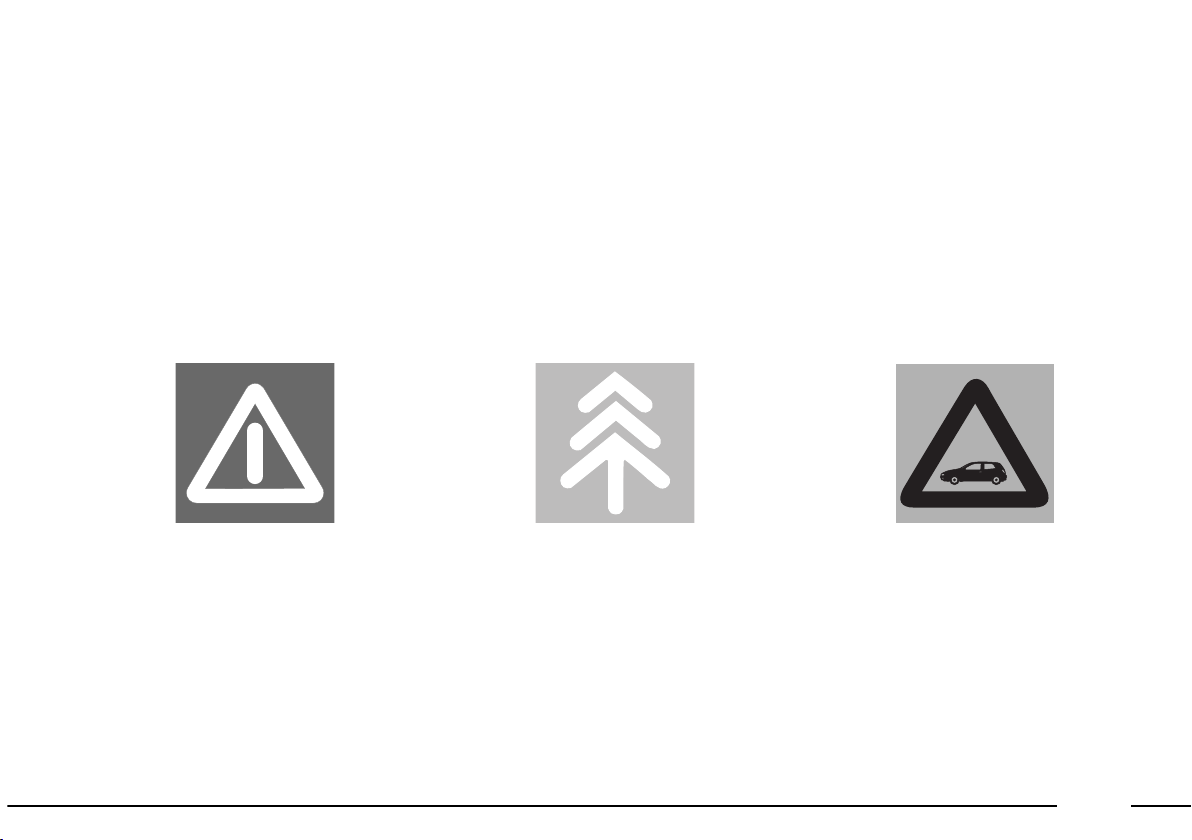
THE SIGNS TO HELP YOU DRIVE CORRECTLY
The signs you see on this page are very important. They highlight those parts of the owner handbook where,
more than anywhere else, you should stop for a minute and read carefully.
As you can see, each sign has a different image to make it clear and easy to identify the subjects in the different areas:
Personal safety.
Attention. Total or partial failure to
follow these instructions can cause
serious danger for safety of people.
Protecting the environment.
It indicates the correct procedures to
follow to ensure that the car does not
harm the environment.
Well-being of the car.
Important: Total or partial failure to
follow these instructions will result
in the risk of serious damage to the
car and sometimes invalidates the
warranty as well.
3
Page 5
4
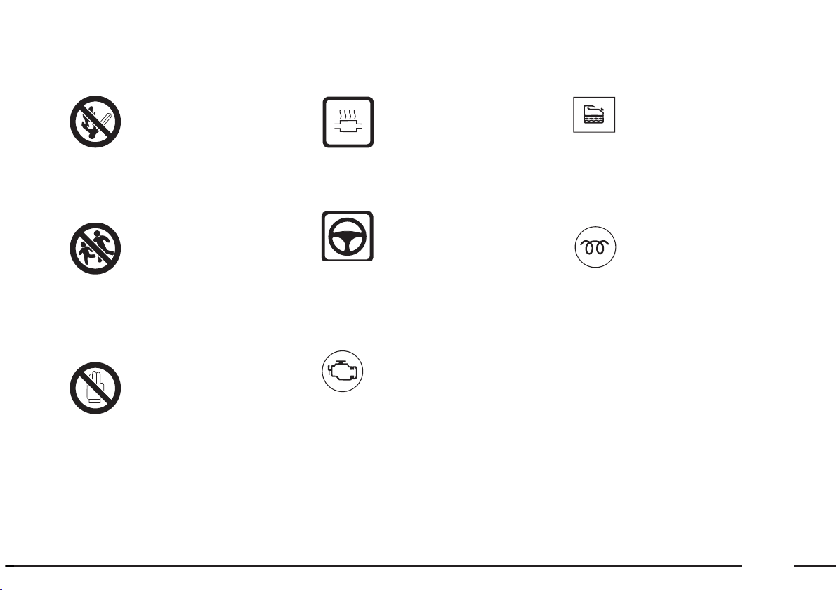
Expansion tank
Do not remove the cap
when the coolant fluid is boiling.
Climate control tubing
Do not open.
High pressure gas.
Belts and pulleys
Moving parts; do not
expose any part of the
body or clothes.
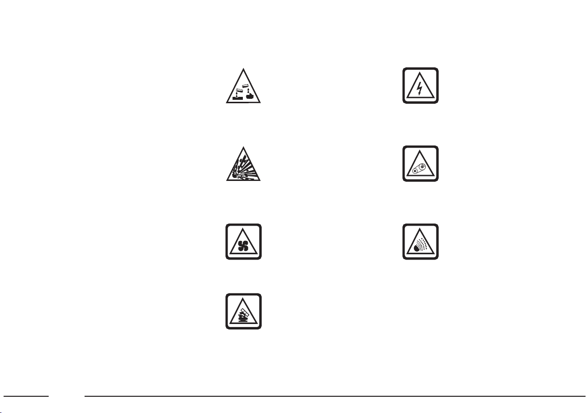
SYMBOLS
On some components of your Fiat
Palio, or near them, are applied specified coloured labels, whose symbols
attract the attention and indicates
important precautions that the user
must observe towards the components under analysis.
A list of symbols to be found on
your Fiat Palio is given below with
the name of the component to which
it relates besides.
It is also indicates the meaning that
the symbol represents depending on
the subdivision of: danger, prohibition, warning, obligation, to which
the symbol belongs.
DANGER SYMBOLS
Coil
High voltage.
Battery
Corrosive fluid.
Battery
Explosion.
Fan
It can start when the
engine is switched off also.
Page 6
5
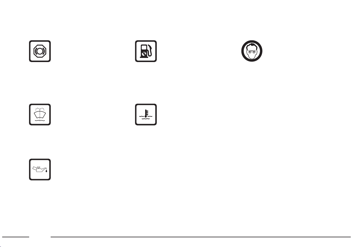
Hydraulic power
steering
Do not exceed the maximum level of the fluid as indicated
on the tank. Use only the fluid prescribed in the “Refueling” chapter.
PROHIBITION SYMBOL WARNING SYMBOLS
Battery
Do not expose to open
flames.
Battery
Keep children away.
Heat guards - belts pulleys - fan
Do not put hands.
Catalytic converter
Do not stay on inflam-
mable surfaces. Refer to
the “Safeguard of the device reducing the emissions” chapter.
INJECTION SYSTEM
FAILURE (red) (diesel
versions)
When there is a fault in the injection
system.
The warning light should come on
when the ignition key is turned to
MAR and go out after a few seconds.
WATER IN DIESEL FUEL FILTER versions (amber) (diesel version)
When there is water in the diesel fuel filter. have the condense drained out
by a Fiat Dealership.
GLOW PLUGS
(amber)
(diesel version)
When the ignition key is turned to
the MAR position. The warning light
will go out when the glowplugs reach
the correct temperature
Page 7
6
OBLIGATION SYMBOLS
Battery
Protect eyes.
Battery
Jack
Refer the owner
handbook.
Expansion tank
Use only the fluid pre-
scribed in the “Refueling” chapter.
Engine
Use only the lubricant
prescribed in the
“Refueling” chapter.
Unleaded fuel car
Use only unleaded fuel
87 R.O.N.
Windscreen wiper
Use only the fluid pre-
scribed in the “Refueling”
chapter.
Brake circuit
Do not exceed the max-
imum level of the fluid as
indicated on the tank. Use only the
fluid prescribed in the “Refueling”
chapter.
Page 8

7
SUMMARY
READY TO GO
GETTING TO KNOW YOUR CAR
DRIVING YOUR CAR
IN AN EMERGENCY
CAR MAINTENANCE
TECHNICAL SPECIFICATIONS
INDEX
Page 9

READY TO GO
Sit comfortably in your car and get ready to...
read.
The following pages tell you everything you need to
know to start off in the best way: that is to say, in
total safety, right from the start.
In a few minutes you will be confident with warning
lights, instruments and main devices.
All adjustments must be made when the car is stationary.
DASHBOARD INSTRUMENT HOLDER ......... PAGE 9
INSTRUMENT PANEL .......................................... PAGE 10
KEYS............................................................................ PAGE 11
SEATS ........................................................................ PAGE 11
HEAD RESTS ........................................................... PAGE 11
SAFETY BELTS ........................................................ PAGE 12
STEERING COLUMN STALKS ........................... PAGE 13
REARVIEW MIRRORS ........................................... PAGE 14
MANUAL CLIMATE CONTROL ........................ PAGE 14
HAZARD LIGHTS .................................................. PAGE 14
COMMAND SWITCHES .......................................PAGE 15
ELECTRIC WINDOW WINDER ....................... PAGE 15
BOOT ........................................................................ PAGE 16
ENGINE BONNET ............................................... PAGE 16
DOORS ..................................................................... PAGE 17
AT THE FILLING STATION.................................. PAGE 18
8
Page 10

9
1. Adjustable side air vents - 2. Vents for air dispatch to side windows - 3. Adjustable central air vents - 4. Commands and
pilot lights - 5. Sound system seat - 6. Switch for hazard lights - 7. Digital clock - 8. Command lever of windscreen/rear win-
dow wiper and washer - 9. Instrument panel and pilot lights - 10. Air bag - 11. External light command lever - 12. Object box -
13. Climate command - 14. Cigar lighter - 15. Ashtray - 16. Horn Pad - 17. Ignition switch - 18. Access to the fuse box -
19. Lever for opening hood to access engine.
P4E02269
DASHBOARD INSTRUMENT HOLDER
The presence and the position of the instruments and indicators may vary according to the version of your car.
fig. 1
Page 11
10
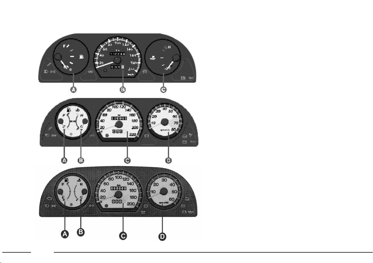
VERSIONS 1.2 EL - ELX
A
- Fuel level gauge with reserve
warning light.
B - Speedometer, kilometre
counter and trip meter.
C - Engine coolant temp. gauge.
VERSIONS 1.6 - GTX
A
- Fuel level gauge with reserve
warning light.
B - Engine coolant temperature
gauge.
C - Speedometer, kilometre
counter and trip meter.
D - Rev counter.
fig. 2
P4E02270
fig. 3
P4E02271
INSTRUMENT PANEL
VERSION 1.9 D EL-ELX
A
- Fuel level gauge with reserve
warning light.
B - Engine coolant gauge.
C - Speedometer, kilometre
counter and trip meter.
D - Rev counter.
P4E02671
Note: Dial gauge background
colours for illustrative purpose only.
Page 12
11
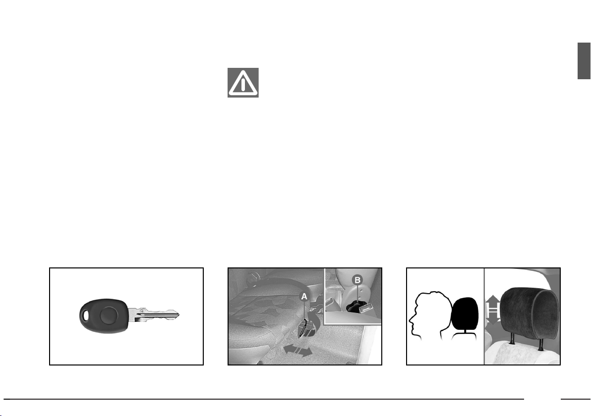
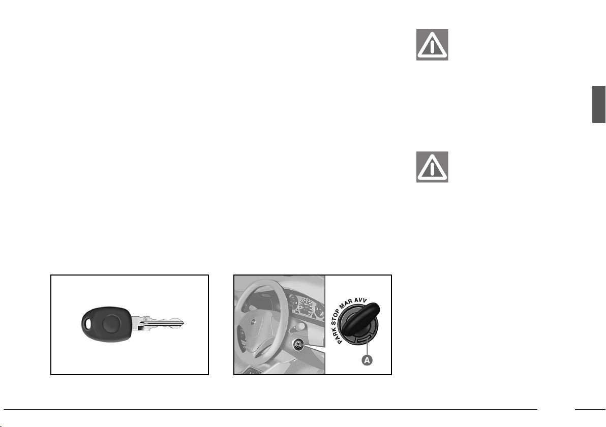
KEYS
A set of 2 keys are provided with
the car for fig. 5:
– ignition;
– locking/unlocking the front doors;
– locking/unlocking the boot.
STEERING COLUMN LOCK
It is automatically locked when the
ignition key is removed. It is
unlocked when the key is turned to
MAR; lightly move the steering
wheel in either direction if the rotation of the key is difficult.
fig. 5
P4E02062
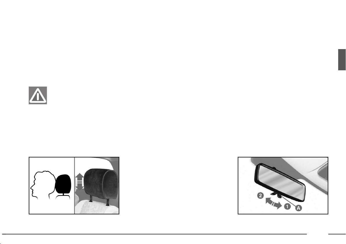
HEAD RESTS
Adjust the headrest fig. 7 such that
the nape, and not the neck, rests on
them, making sure that they are
locked in the desired position. Refer
to the “Getting to know the car”
chapter.
SEATS
All adjustments must
be made when the car is
stationary.
Seat adjustment fig. 6.
A - To move the seat forwards or
backwards.
B - Seat back inclination adjust-
ment.
fig. 7
P4E01603
fig. 6
P4E01989
Page 13
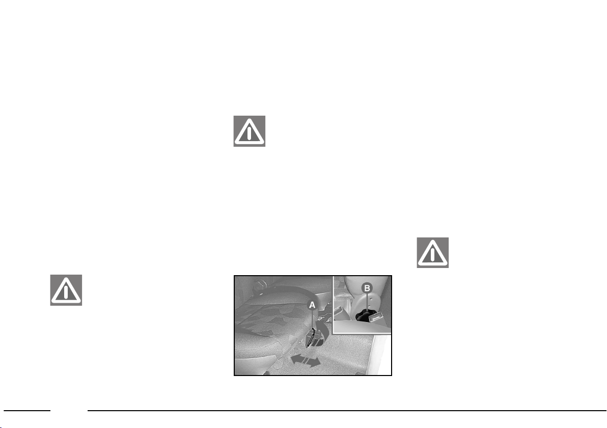
12
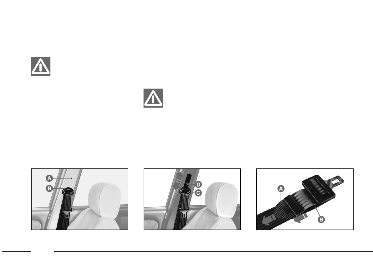
Adjusting the central rear seat
belt fig. 10
To tighten:
pull the end A (this
operation can be carried out also
with the seat belt already fastened).
To loosen: pull length B holding
the buckle at right-angles to the belt.
fig. 10
P4E01607
SAFETY BELTS
The adjustments
described below must be
performed before dri-
ving. Avoid performing these
operations when the car is in
motion.
Adjusting the height
of the front seat belts
Fig. 8:
fix the loop in point A or B
fig. 9
P4E01796
Fig. 9
To lift:
lift the loop C.
To lower: keeping the knob
pressed D move the loop C.
fig. 8
P4E01783
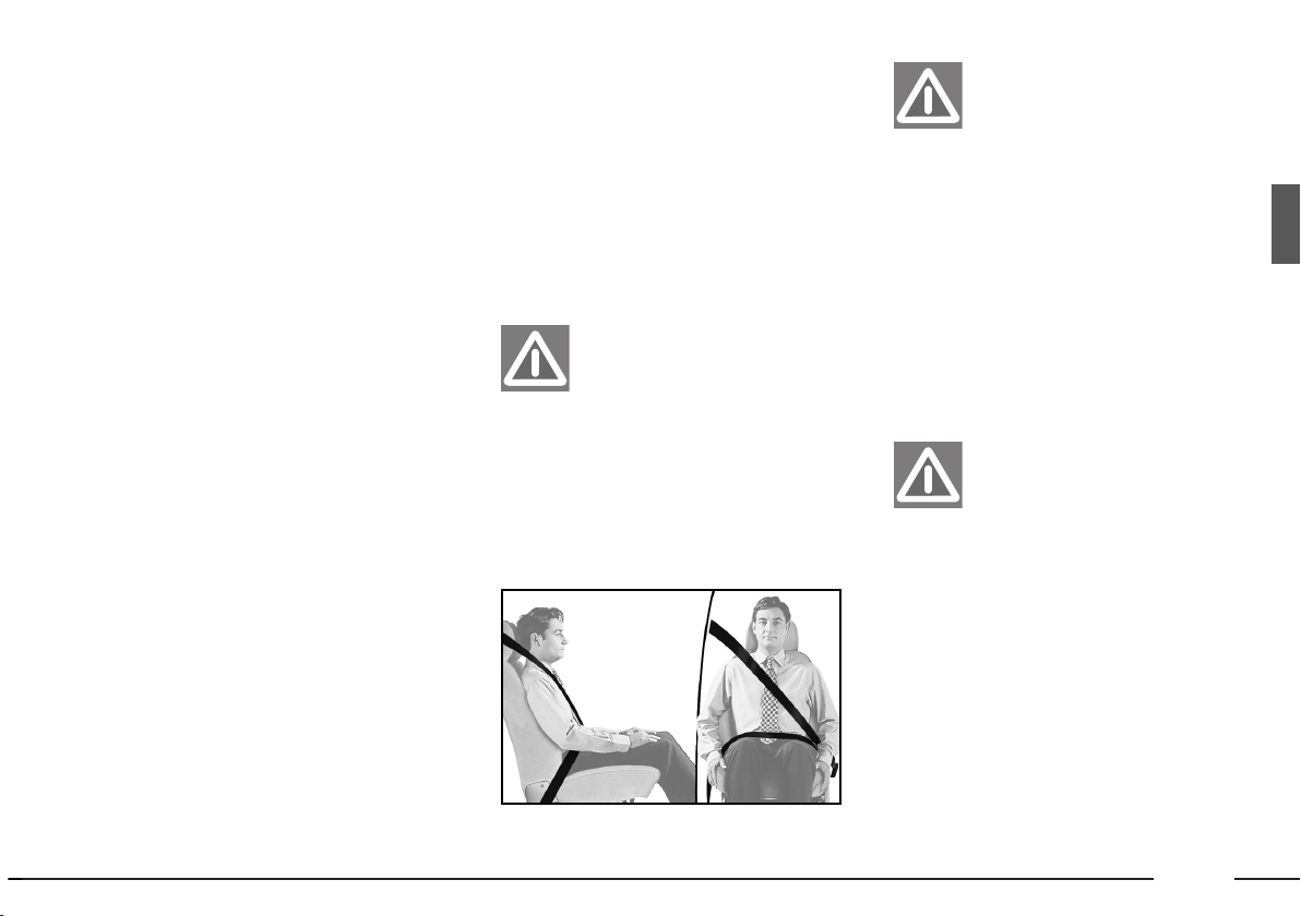
To ensure maximum
protection, keep the
backrest in the upright
position, lean back into the seat
and ensure that the seat belt
adheres closely to torso and
hips. Do not use the seat belt
when the seat back is reclined.
Page 14
13
STEERING COLUMN STALKS
RIGHT-HAND STALK fig. 12
In position A = left turn indicator
lights on.
In position
B = right turn indicator
lights on.
Pulled towards the steering wheel
= flicks.
Ring turned on
O = lights switched
off.
Ring turned on 3
= parking
lights on.
Ring turned on
2
= Low beams.
With ring turned on
2
& stalk
towards the dashboard = high beams.
Fig. 11
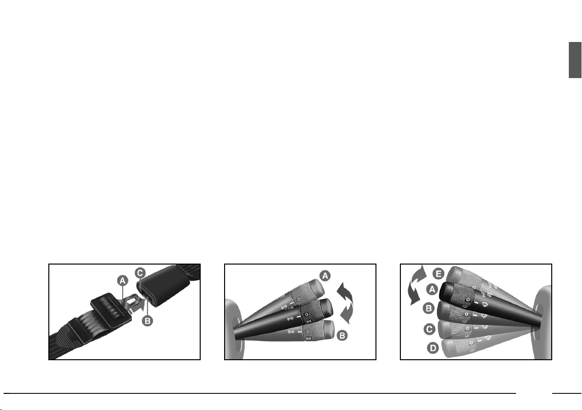
To fasten:
insert tongue A in B
on the buckle.
To loosen: press button C.
fig. 11
P4E01355
fig. 12
P4E02023
LEFT-HAND STALK fig. 13
Position A = Windscreen wipers
OFF.
Position
B = Intermittent wipe.
Position
C = Slow continuous
wipe.
Position
D = Quick continuous
wipe.
Position
E (not fixed) = Quick continuous wipe. This is a unique antipanic feature.
Stalk pulled towards the steering
wheel = windscreen washer activated.
Thrust towards the dashboard =
rear window washer/wiper.
Ring on O position = Rearwind
screen wiper OFF.
Ring at
''
position = Rear wind-
screen wiper ON.
fig. 13
P4E01682
Page 15
14
HAZARD LIGHTS
To switch them on, press the
switch A-fig. 16.
To switch them off, press the
switch again.
The use of the hazard
lights is ruled by the
road code of the
Country in which you are driving and should be followed
accordingly.
fig. 16
P4E02286
fig. 15
P4E02285
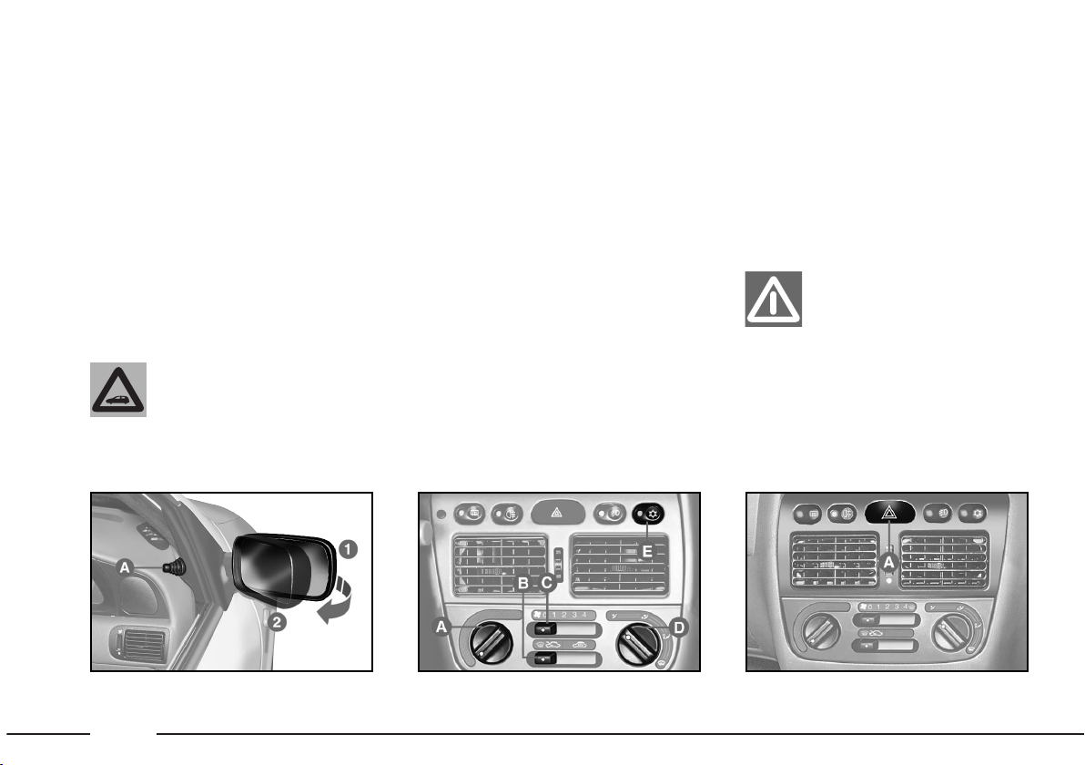
MANUAL CLIMATE CONTROL
CONTROLS fig. 15
A
- To adjust the temperature.
B - Air recirculation selector.
C - Fan speed selector.
D - Air distribution control.
E - System on/off switch.
fig. 14
P4E02007
If the dimension of the
mirror causes difficulties
in a narrow place, fold
from the position 1 to the position 2.
REARVIEW MIRRORS
IMPORTANT The reflecting surface of the left-hand mirror is parabolic to increase viewing range.
Consequently, the dimension of the
reflected image is reduced, giving the
impression that the object is more
distant than it really is.
For the adjustment, operate knob
from inside of car
A-fig. 14.
Page 16
15
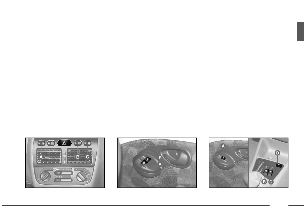
COMMAND
SWITCHES
Switches fig. 17.
A - Rear windscreen heater switch.
B - Front fog light switch with LED.
C - A/C on/off switch.
ELECTRIC WINDOW WINDER
FRONT ELECTRICAL WINDOW WINDERS
Press the switch fig. 18 to lower
the window. Raise the switch to
wind up the window.
A - Switch for adjusting front left
window.
B - Switch for adjusting front right
window.
Each door handle has a switch on it
to raise/lower its window.
fig. 17
P4E02287
fig. 18
P4E02011
fig. 19
P4E02012
ELECTRIC REAR WINDOWS
fig. 19
A
- Switch on door handle.
B - Rear left-hand window switch.
C - Rear right-hand window switch.
D - Rear window enable switch.
Page 17
16
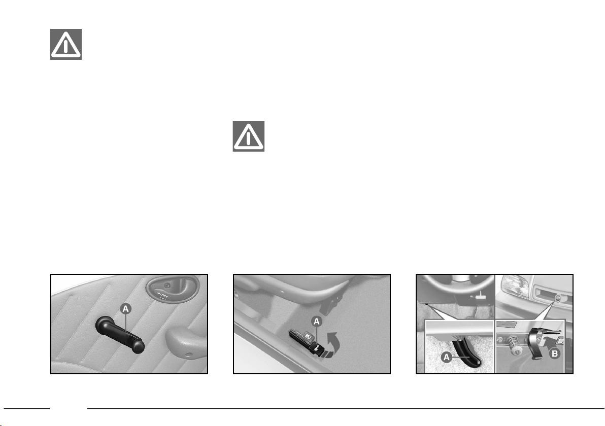
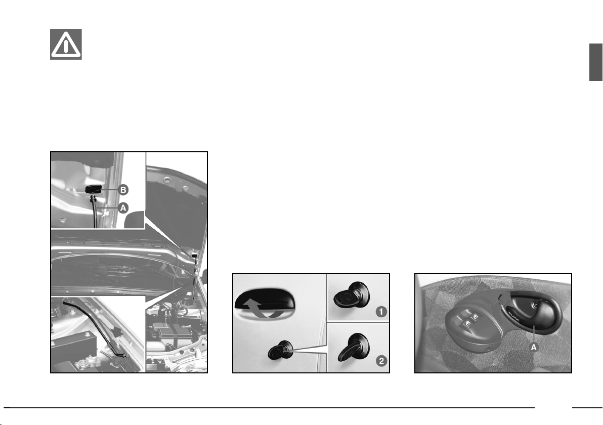
ENGINE BONNET
To open: pull lever A-fig. 22.
Press lever B and lift the bonnet.
Insert the end of rod A-fig. 23 in
the recess B on the bonnet.
To close: remove rod
A from
recess B and refit it in its clip. Lower
the bonnet until it is about 20 cm
above the engine compartment and
let it fall. Make sure the bonnet is
locked.
fig. 22
P4E02124
Open the boot only
when the car is stationary.
EXTENDING THE BOOT
For extending the boot space by
adjusting the rear seat refer to the
chapter on “Getting to know your
car”.
fig. 21
P4E01944
BOOT
From outside the car: use ignition
key to open.
From inside the car: pull lever
A-
fig. 21.
Improper use of the
electrical windows can be
dangerous.
Before and during their operation ensure that passengers are
not at risk from the moving glass
either by personal objects getting
caught in the mechanism or by
being injured by it directly.
Always remove the ignition key
when you get out of the car to
prevent the electric windows being operated accidentally and
constituting a danger to the people left in the car.
fig. 20
P4E01791
MANUAL WINDOWS fig. 20
To wind down/up the door windows operate the command A handles.
Page 18
17
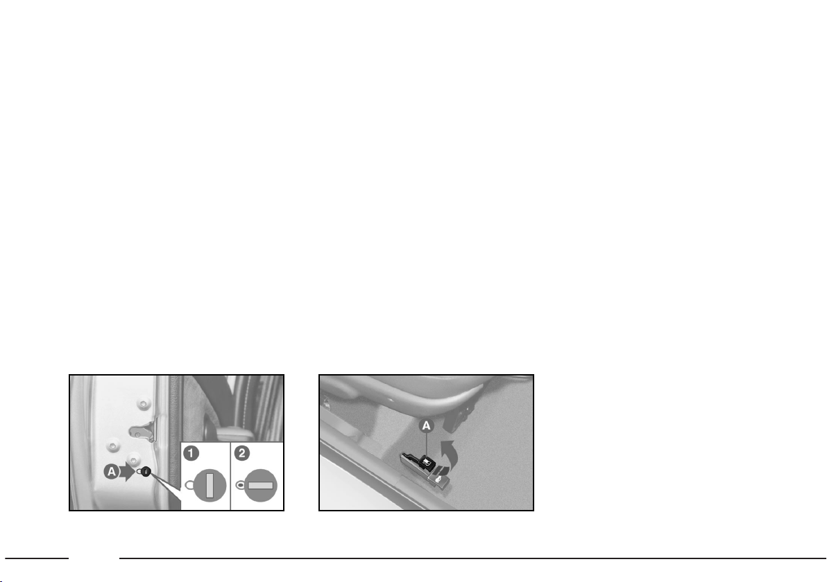
DOORS
Turn the key fig. 24:
1 - door locked.
2 - door unlocked
Pull the handle to open.
From inside:
– to open - pull handle
A-fig. 25;
– safety lock - with the door closed
press the lever
A.
It is possible to insert the safety
lock with open door only on the passenger side on versions without centralized locking.
fig. 24
P4E01367
fig. 25
P4E02015
CENTRAL DOOR LOCKING
SYSTEM
To lock/unlock all the doors at the
same time:
– from outside the car, turn the key
in the lock;
– from inside the car, with closed
door, press (to lock) or pull(to
unlock) one of the front door opening lever.
The bonnet should be
opened only when the
car is stationary.
fig. 23
P4E01365
Page 19
18
AT THE FILLING
STATION
Refuel the car with unleaded fuel
only with octane-number (R.O.N.)
equal to 87.
Lift the lever
A-fig. 27 to unlock
the access door of fuel tank plug.
fig. 27
P4E01945
When refueling, position the plug in
the adequate seat on the door, as
shown in fig. 28.
CHILD SAFETY LOCK
(rear doors)
This ensures that the rear doors
cannot be opened from inside the
car.
With the head of the ignition key
turn the device
A-fig. 26.
Position
1 - activated device.
Position
2 - deactivated device (a
little yellow mark certificates the
occurred connection).
fig. 26
P4E01612
Page 20
19
Ideally, refuel the car
before the reserve warning light illuminates.
Driving in fuel shortage conditions can cause irregular supply
with negative effects on the
exhaust and catalytic system.
A damaged catalytic
convertor means harmful emissions and conse-
quent environment pollution.
NEVER go close to the
tank filler with naked
flames or lit cigarettes:
Also avoid going too close to
the fuel tank filler area, to avoid
inhaling harmful vapours.
NEVER fill leaded fuel
in the car (even in an
emergency) as the cat-
alytic muffler will get irrebarably damaged.
Page 21

GETTING TO KNOW YOUR CAR
You should read this chapter sitting comfortably in
your new Fiat Palio. This way you can see the parts
described in the handbook at a glance and immediately check out what you have just read for yourself.
You will quickly become familiar with your Fiat Palio,
and its control and other features. Later, when you start
the engine and join the traffic, you will make a host of
other pleasant discoveries.
INSTRUMENTS ......................................................... PAGE 33
WARNING LIGHTS ................................................ PAGE 35
HEATING/
CLIMATE CONTROL SYSTEM ............................ PAGE 37
MANUAL CLIMATE CONTROL SYSTEM ....... PAGE 38
STEERING COLUMN STALKS ............................. PAGE 41
CONTROLS ............................................................... PAGE 43
INTERIOR EQUIPMENT ........................................ PAGE 45
DOORS ........................................................................ PAGE 48
BOOT .......................................................................... PAGE 51
BONNET .................................................................... PAGE 54
HEADLIGHTS ............................................................ PAGE 56
ABS ............................................................................... PAGE 56
AIR BAG ...................................................................... PAGE 58
SOUND SYSTEM....................................................... PAGE 60
AT THE FILLING STATION ................................. PAGE 62
PROTECTING THE ENVIRONMENT ............... PAGE 63
20
KEYS ............................................................................. PAGE 21
IGNITION SWITCH ............................................... PAGE 21
INDIVIDUAL SETTINGS ........................................ PAGE 22
SEAT BELTS ............................................................... PAGE 24
TRANSPORTING CHILDREN IN SAFETY ...... PAGE 29
PRETENSIONER ....................................................... PAGE 32
Page 22
21
IGNITION
SWITCH
The key can turn to 4 different po-
sitions fig. 2:
–
STOP: engine switched off, extractable key, steering column lock.
Some electrical devices (e.g. door centralized lock etc.) remain operational.
–
MAR: ride position. All electrical
devices are operational.
–
AVV: engine starting.
–
PARK: engine switched-off, parking lights switched on, extractable key,
steering column lock. To turn the key
in PARK position, press the button
A.
In the event of a breakin (e.g. attempted theft),
have the car checked at a
Fiat Dealership prior to driving
again.
fig. 1
P4E02062
KEYS
Two keys are provided with the car
& (fig. 1) they are used for:
– the ignition;
– the front doors;
– the boot door.
Together with the keys, a self-stick
label is supplied. On this label is reported the number to be quoted to
Fiat Dealership when ordering duplicate keys.
fig. 2
P4E02017
When getting out of the
car, always remove the
key, to avoid someone ac-
cidentally activating the controls.
Remember to engage the hand
brake, ensuring complete lockup
of the car, engage gear and leave
the wheels steered. If the car is
parked on a very sloping road, we
recommend you lock the wheels
also with a wedge or a stone.
Never leave children alone in an
unattended car.
Page 23
Once you have released the lever,
check that the seat is firmly locked in
the runners by trying to move it back
and forth. Failure to lock the seat in
place could result the seat moving suddenly and the driver losing control of
the car.
Adjusting the reclining seat
back
Turn knob B-fig. 3 until the back
reaches the reclination you desire.
Do not remove the seats
nor carry out maintenance and/or repair oper-
ations on them. Improper operations can compromise safety device operation. Always go to a Fiat Dealership.
22
Moving the seat backwards or
forwards
Lift the lever A-fig. 3 and push the
seat forwards or backwards; you are
in the correct position for driving
when your hands are resting on the
steering wheel rim and your arms are
slightly bent.
Only make adjustments
when the car is stationary.
STEERING COLUMN LOCK
Engagement:
After turning the key
to position STOP or PARK remove it
and turn the steering wheel till it locks .
To release: Gently move the steering wheel from side to side as you turn
the ignition key to MAR.
Never remove the ignition key while the car is
moving. The steering
wheel will automatically lock as
soon as you turn it. This also applies when the car is being towed.
INDIVIDUAL SETTINGS
FRONT SEATS fig. 3
fig. 3
P4E01989
Page 24
23
HEAD RESTS
Front seats fig. 4
To improve passenger safety, the
height of the head restraints can be adjusted. They lock into place automatically.
fig. 4
P4E01603
Remember that the
head restraints should be
adjusted to support the
back of your head and not your
neck. Only if they are in this position will they be able to provide
effective protection in the event
of a rear-end shunt.
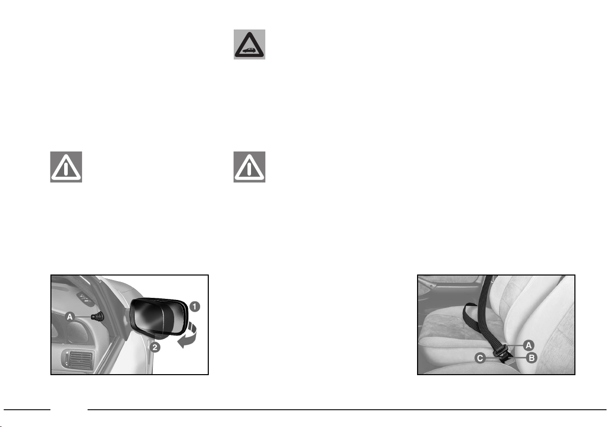
DRIVING MIRROR fig. 6
This mirror can be adjusted. Move
lever A to shift the mirror to the following positions:
1) anti glare position;
2) standard position.
fig. 6
P4E01375
Page 25
24
SEAT BELTS
USING THE SEAT BELTS
(for the front seats) fig. 8
To fasten the seat belts, take the
tongue of fastener A and push it into
buckle B, until you hear it click.
Pull the seat belt gently. If it jams, let
it rewind a little then pull it out again
without jerking.
fig. 8
P4E01376
DOOR MIRRORS
To adjust, operate the knob inside
the car A-fig. 7.
Make sure that the car is stationary
and the handbrake is on before you
adjust mirrors.
The reflecting surface
of the left-hand mirror is
parabolic to increase
viewing range. Consequently,
the dimension of the reflected
image is reduced, giving the
impression that the object is
more distant than it really is.
fig. 7
P4E02007
When driving, the door
mirrors must always be in
the extended position 1.
If the mirror makes it
difficult to get through
narrow gaps, fold it from
1-fig. 7 to position 2.
Page 26

25
To unfasten the seat belts, press button C. Guide the seat belt with your
hand while it is rewinding, to prevent
it from twisting.
The seat belt reel mechanism will
adapt the belt to the body of the person wearing it, offering freedom of
movement.
When the car is parked on a steep
slope the reel mechanism may lock;
this is normal.
The reel mechanism prevents the
webbing coming out when it is jerked
or if the car brakes sharply, as in a collision or when cornering at high speed.
To ensure maximum
protection, keep the
backrest in the upright
position, lean back into the seat
and ensure that the seat belt adheres closely to torso and hips.
Do not use the seat belt when the
seat back is reclined.
Always adjust the height of the seat
belt to fit the person wearing it. This
could greatly reduce the risk of injury
in the case of collision.
The belt is adjusted properly when
the webbing passes approximately
halfway between the edge of the
shoulder and the neck.
ADJUSTING THE HEIGHT OF
THE SEAT BELTS
Make the height adjustment when the car is stationary.
fig. 9
P4E01783
Adjust the seat belt height only when
the car is stationary.
Fig. 9: fasten the loop in A or B.
Fig. 10: The seat belt can be adjust-
ed on four different heights.
To raise the belt: raise loop C to
the required position.
To lower the belt: press knob (D)
and move loop (C) down to the required position at the same time.
After adjustment always check that
the seat belt is locked by pushing loop
C downwards without pressing knob
D.
fig. 10
P4E01796
Page 27

26
Releasing knob D, press
a little further to trigger
the anchor device. This
ensures the belt is locked into a
stable position if not already
done.
Page 28
27
GENERAL INSTRUCTIONS
FOR THE USE OF THE SEAT
BELTS
The driver is obliged to respect (and
check that the car occupants respect)
all local traffic laws regarding the use
of seat belts.
Always fasten seat belt.
To travel with seat belts
unfastened increases the
risk of serious injury or death in
the event of a crash.
fig. 13
P4E02064
If the seat belt is subjected to high stress, for
example after a collision,
it must be replaced completely
together with the anchors, anchor fixing screws and the pretensioner, if the car is equipped
with, in fact, even if the seat belt
does not seem damaged, the seat
belt could have lost its resistance
proprieties.
The belt webbing must
not be twisted, make sure
that it is well stretched
out and fits close to the passenger’s body. The upper section
must pass over the shoulder and
cross the chest diagonally. The
lower section must fit close
across the passenger’s hips and
not the abdomen to prevent
them sliding forward fig. 13. Do
not use devices (clips, fasteners
etc.) to prevent the belt adhering
to the passenger’s body.
Page 29
28
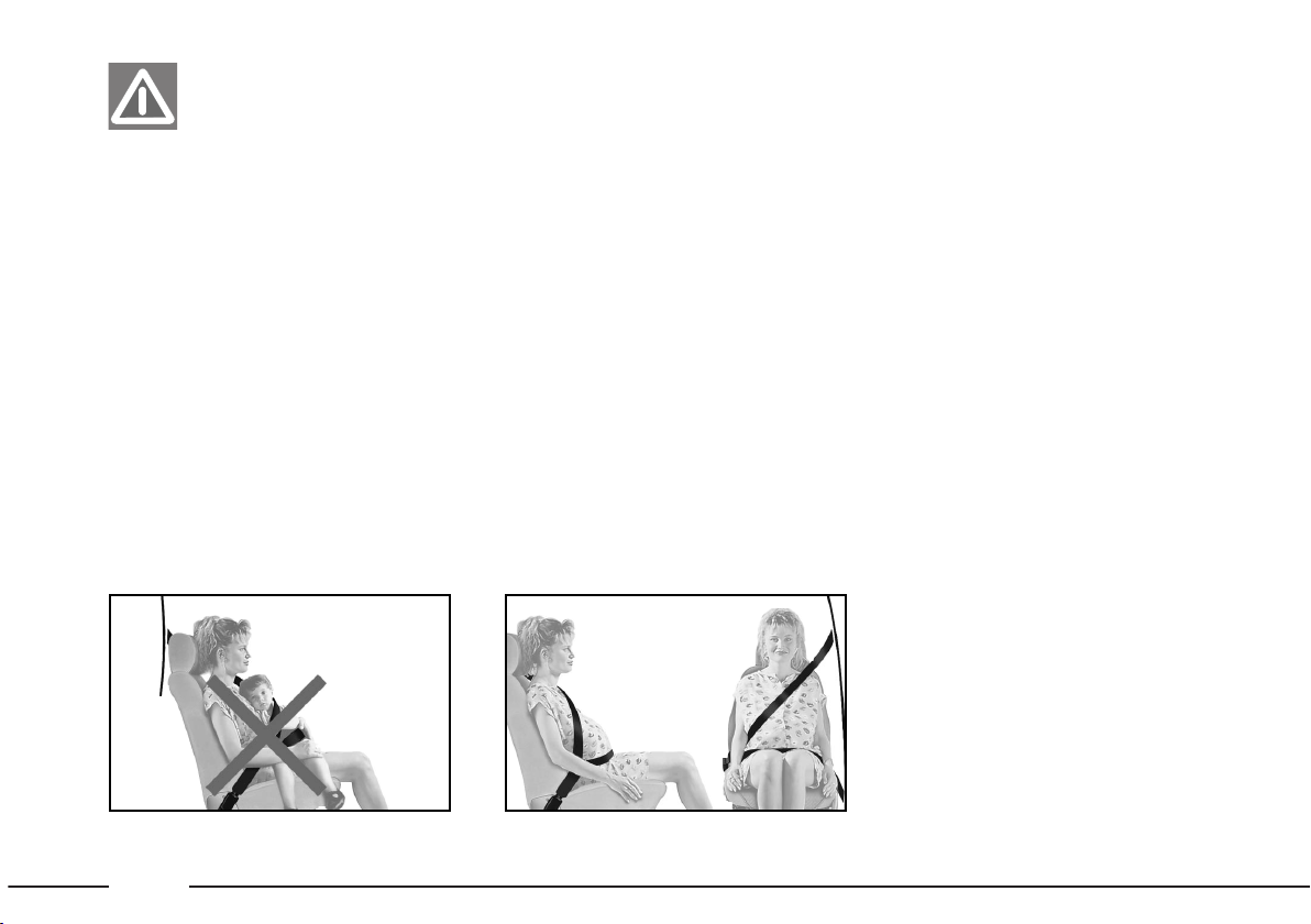
Do not travel with a
child sitting on the lap of
a passenger using one
seat belt to protect both (fig. 14).
Seat belts are also to be worn by expectant mothers: the risk of injury in
the case of accident is greatly reduced
for them and the unborn child if they
are wearing a seat belt.
Of course they must position the
lower part of the belt very low down
so that it passes under the abdomen
fig. 15
HOW TO KEEP THE SEAT
BELTS IN PROPER WORKING
ORDER AT ALL TIMES
1)
When wearing the seat belts, always ensure they are not twisted and
are free to wind in and out.
2) Following a serious accident, replace the belt being worn at the time,
even if it does not seem damaged.
3) When cleaning the belts, wash
them by hand with water and neutral
soap, rinse them and let them dry in
the shade. Do not use strong detergents, bleach, colouring or any other
chemical substance that could weaken
the fibres.
4) Do not allow the reel mechanisms
to get wet: they are only guaranteed
to work properly if they remain dry.
fig. 14
P4E02065
fig. 15
P4E02066
Page 30
29
TRANSPORTING
CHILDREN
IN SAFETY
For optimal protection in the event
of a crash, all passengers must be seated and wearing adequate restraint systems.
This is especially relevant for children.
A child’s head is larger and heavier
than an adult’s head with respect to
their body weight. Moreover, a child’s
muscular and bone structure is not fully developed. For these reasons, children require specific restraint systems,
different from those required by adult
passengers.
Child’s restraint systems are classified into the following four weight
groups, fig. 16:
Group 0 weight 0-10 kg
Group 0 weight 9-18 kg
Group 0 weight 15-25 kg
Group 3 22-36 weight kg.
The groups partially overlap. This is
because there are systems which cover more than one weight group.
Children weighing more than 36 kg
or taller than 1.5 m are, with reference
to restraint systems, considered adults
and can wear normal seat belts.
fig. 16
P4E00197
The seat shown in fig. 16 is suitable
for children weighing between 18-36
kgs.
Page 31

30
There are child restraints for groups 0 and
1 which are fastened with
the car seat belts by means of an
attachment on the seat back. The
child is then secured to the seat
with specific straps. Due to their
weight, child seats can be dangerous if they are fitted incorrectly with a cushion placed between the seat and the car seat
belts. Always attain carefully to
the specific installation instructions attached.
We recommend seating
children on the rear seat.
This is the most protect-
ed position in the event of a
crash.
GROUP 0
Babies up to 10 Kg are to be seated
in a cot type seat supporting the child’s
head, facing backwards. This ensures
there is no stress on the child’s neck
in sudden decelerations.
The cot is secured with the seat
belts, as shown in
fig. 17. The child
must be strapped to the carrier with
its incorporated straps.
GROUP 1
Children from 9 kg are to be seated
facing forward in child seats with front
cushions. The seat belt secures both
seat and child fig. 18.
fig. 17
P4E00198
fig. 18
P4E00199
The figure is only an example. Follow the instructions for fastening
the specific child restraint
system you are using.
The figure is only an example. Follow the instructions for fastening
the specific child restraint system
you are using.
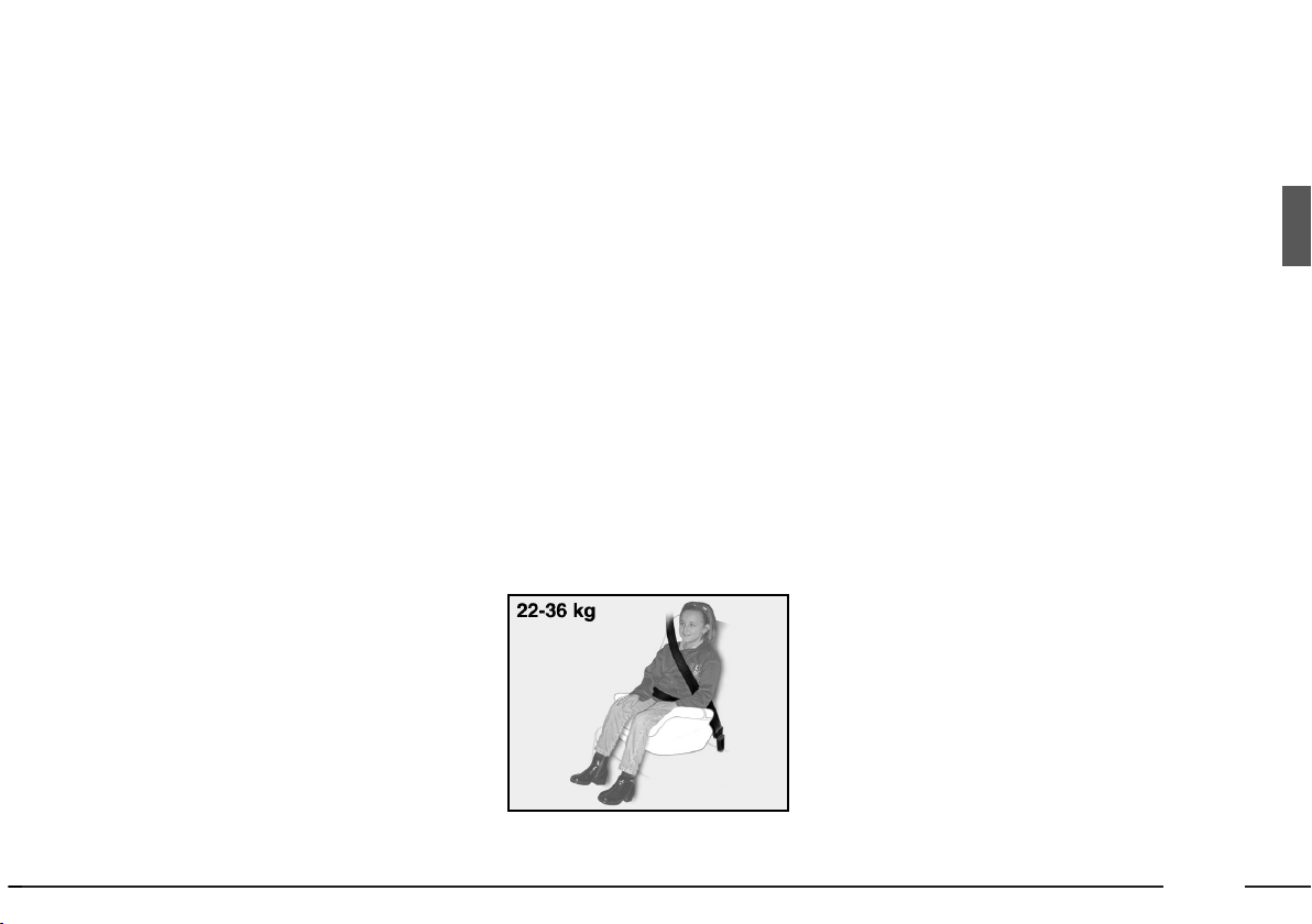
Children from 18 kg up only require
a cushion to lift them
fig. 20. The size of the child’s chest no
longer requires a support to space the
child’s back from the seat back.
Children taller than 1.50 m can wear
seat belts like adults.
fig. 20
P4E00201
The figure is only an example. Follow the instructions for fastening
the specific child restraint system
you are using.
Page 32

The figure is only an example. Follow the instructions for fastening
the specific child restraint system
you are using.
31
GROUP 2
Children from 15 kg can be secured
directly with the car seat belts. The
child seat has the purpose of positioning the child correctly with respect
to the seat belt, so that the diagonal
section crosses the child’s chest and
never the throat, and that the horizontal section fits snugly on the child’s
hips and not to the abdomen fig. 19.
fig. 19
P4E00200
5) Always check the seat belts do
not fit around the child’s throat.
6) While travelling, do not let the
child sit incorrectly or release the
belts.
7) Passengers should never carry
children on their laps. No-one, however strong they are, can hold a child
in the event of a crash.
8) Replace the child restraint system
after an accident.
A summary of safety precautions to follow when transporting children.
1)
Child restraint systems should be
installed on the rear seat as this is the
most protected area in the car in the
event of a crash.
2) Adhere to the instructions for fastening the specific child restraint which
you are using. These instructions must
be provided by the manufacturer.
Keep the child restraint system installation instructions with the car documents and this Handbook. Never use
a child restraint system without installation instructions.
3) Always check the seat belt is well
fastened by pulling the webbing.
4) Only one child is to be strapped
to each restraint system.
Page 33

32
PRETENSIONERS
The pretensioner does not require
any maintenance or lubrication. Any
modification of its original state invalidates its efficiency. If, as the result of
exceptional natural occurrences
(floods, sea storms etc.) the device become soaked through with water and
mud, it is essential that it be replaced.
The pretensioner will give maximum
protection when the seat belt adheres
snugly to the wearer’s chest and hips.
To render the protective action of
the front seat belts even more effective, some versions of Fiat Palio are fitted with pretensioners. These devices
“feel” that a violent collision is in
progress via a sensor, and pull back a
few centimeters of webbing. In this
way the pretensioner ensures that the
belt is adhering perfectly to the body
before the belt begins to hold back the
wearer.
When the pretensioner has been
triggered the retractor will lock.
The seat belt cannot be drawn back
up even when guiding it manually.
When the pretensioner is triggered
a small amount of smoke may be produced. The smoke is not harmful and
does not indicate the beginning of a
fire.
Under no circumstances
should the components of
the pretensioner be tam-
pered with or removed. Any interventions should be carried out
by qualified and authorized personnel. Always contact a Fiat
Dealership
Page 34

33
The pretensioners can
only be used once. After a
collision that has trig-
gered it, have it replaced at a Fiat Dealership. The device will last
for 10 years from the date of production given to the adhesive label. Replace the pretensioners as
this date approaches.
INSTRUMENTS
SPEEDOMETER (SPEED INDICATOR) fig. 21-22
A
- Kilometre counter.
B - Speedometer.
fig. 22
P4E01839
Operations involving
banging, vibrations or
heating (exceeding 100
C° for a maximum of 6 hours) in
the area around the pretensioner may trigger or damage the device. Vibrations from rough road
surfaces or accidental jolting
caused by mounting pavements
etc. do not have any effect on the
pretensioner. If, however, you
need any assistance, go to a Fiat
Dealership.
C - Partial kilometer counter (Trip-
meter).
D - Trip counter reset button. Press
to reset.
FUEL GAUGE fig. 23
The needle indicates the amount of
fuel in the tank.
When the fuel reserve warning light
A
comes on it means that there are
about 5.5-7.5 litres of fuel in the tank.
E - tank empty.
F - tank full.
fig. 21
P4E01380
fig. 23
P4E01840
Page 35

34
If the gauge reaches the
red section, stop the engine immediately and go
to a Fiat Dealership.
Do not travel with the fuel tank almost empty: as gaps in fuel delivery
could damage the catalyser.
ENGINE COOLANT TEMPERATURE GAUGE fig. 23-24
Under normal conditions, the needle
may hover around the scale according
to the car use and engine cooling system management that the system selfadjusts continually, but it should always
remain out of the red (danger) section.
REV COUNTER fig. 25
The needle in correspondence with
the red marks indicates over-revving
that can damage the engine. So it has
to be avoided.
IMPORTANT The electronic injection control system will progressively cut off the flow of fuel when the
engine is over-revving and the engine
will consequently loose power.
fig. 24
P4E01383
fig. 25
P4E01841
DIGITAL CLOCK fig. 26
The clock displays time in a 24 hour
format.
To set hour: press the button
A.
To set minute: press the button
B.
Each time the button is pressed, the
number will change of a unit.
Keeping the button press for a few
seconds, you will have the automatic
quick advancement.
As you near the desired hour, release the button and complete the setting with individual pressures.
fig. 26
P4E02277
Page 36

35
WARNING
LIGHTS
The warning lights come on in the
following circumstances:
BATTERY NOT
CHARGING PROPERLY (red) When there is
a fault in the current gen-
erating system.
Go to a
Fiat Dealership and pre-
vent deploying the battery.
When the key is turned to
MAR the
light comes on but should go out the
moment the engine is started.
LOW ENGINE OIL
PRESSURE (red)
When
the engine oil pressure
drops under the normal
value.
When the key is turned to
MAR the
light comes on but should go out the
moment the engine is started.
A delay in the light going out is ac-
ceptable only when the engine is idling.
If the engine has been heavily taxed,
the light may flash when the engine returns to idle. The light should however go out when you accelerate slightly.
v
w
If the v warning light
comes on while the car is
moving, stop the engine
immediately and contact a Fiat
Dealership.
INJECTION SYSTEM
FAILURE (red) (petrol
version) When there is a
fault in the injection system.
When the ignition key is turned to
the
MAR position, the light comes on
but should go out after a few seconds.
The warning light will stay on or
come on when travelling to indicate
imperfect operation of the injection
system with possible loss of performance, poor handling and higher consumption.
g
In these conditions, you can continue driving but you should avoid demanding efforts from the engine or
high speeds. Contact a Fiat Dealer-
shipas soon as possible.
Using the car for long periods when
the warning light is on may cause damage especially when the engine is running irregularly or misfiring. The car
should only be used for short periods
at low speeds.
Occasional and brief lighting of the
warning light is meaningless.
HANDBRAKE ENGAGED / LOW
BRAKE FLUID (red) In
two cases:
1. When the handbrake is applied.
2. when the brake fluid level falls be-
low the minimum level.
x
Page 37

ABS (WHEEL ANTILOCKING SYSTEM) FAILURE (amber) When there is a fail-
ure in the ABS system.
In this case, the normal braking system continues to work although without the ABS assistance. Hence, have
the car seen to at a
Fiat Dealership
as soon as possible.
The warning light should come on
when the key is turned to
MAR and
go out after approximately 2 seconds.
DIRECTION INDICATORS (green) (flashing) When the direction
indicator control stalk is
operated (arrows).
PARKING LIGHTS
(green) When the
side/tail lights are switched
on.
RE
3
MAIN BEAM HEADLIGHTS (blue)
When main beam headlights are switched on
1
AIR BAG FAILURE
(red) When there is an
airbag system failure.
If the x warning light
comes on when travel-
ling, check whether the
handbrake is engaged. If the
warning light stays on and the
handbrake is not engaged, stop
immediately and contact a Fiat
Dealership.
>
Warning light >, with
the engine running, nor-
mally indicates a fault in
the ABS system only. In this case,
the braking system is still efficient, though without the antilocking device. You are advised
to go immediately to the nearest
Fiat Dealership, driving in a manner to avoiding sharp braking and
get the system checked.
û
The warning light should
come on when the key is
turned to MAR and go
out after approximately 4 seconds. If the warning light either
does not come on or comes on
when travelling, stop immediately and go to a Fiat Dealership.
The warning light should come on
when the key is turned to MAR and
go out after approximately 2 seconds.
36
INJECTION SYSTEM
FAILURE (red) (diesel
versions)
When there is a fault in the injection
system.
The warning light should come on
when the ignition key is turned to
MAR and go out after a few seconds.
The warning light will stay on or
come on when travelling to indicate
imperfect operation of the injection
system with possible loss of performance, poor handling and higher consumption.
In these conditions, you can continue driving but you should avoid demanding efforts from the engine or
high speeds. Contact a
Fiat Dealer-
ship as soon as possible.
Prolonged use of the car with warning light can cause damage to the engine, specially in the event of misfiring. The car can only be driven for a
short period of time at low ratios.
Occassional and brief lighting of the
warning light is meaningless.
Page 38

37
HEATING /CLIMATE CONTROL SYSTEM
1 - Windscreen defroster/demister
vents.
2 - Front side window
defroster/demister vents.
3 - Central and side directional vents.
4 - Side vents for sending air to
footwell.
P4E02020
fig. 27
WATER IN DIESEL
FUEL FILTER versions
(amber) (diesel version)
When there is water in the diesel fuel filter. have the condense drained
out by a Fiat Dealership.
GLOW PLUGS
(amber)
(diesel version)
When the ignition key is turned to
the MAR position. The warning light
will go out when the glowplugs reach
the correct temperature.
The warning light has a diagnostic
function to signal pre-heating system
failures (cut-off or short-circuited
glow plugs, blown pre-heating control
unit power fuse, tripped pre-heating
control unit circuit surge and current
protections).
If the warning light flashes for 60 seconds just before the engine is started,
the vehicle can still be started but a
Fiat Dealership should be contacted as soon as possible to have the
anamoly rectified.
Page 39

38
MANUAL CLIMATE
CONTROL SYSTEM
The system is filled with
R134a refrigerant which
will not pollute the envi-
ronment in the event of leakage.
Under no circumstances should
R12 fluid be used as it is incompatible with the system components.
fig. 30
P4E02285
DIRECTIONAL AND ADJUSTABLE AIR VENTS fig. 28
The vents can be rotated upwards or
downwards.
A - Control for allowing adjusting air
flow:
– turned to
O
vent open;
– turned to
ç
vent closed.
B - Control for adjusting direction of
air flow.
C - Side window fixed vent fig. 29.
fig. 28
P4E02288
fig. 29
P4E02022
Page 40

39
CONTROLS (fig. 30)
A
- Air temperature knob (mixing
hot and cold air).
B - Air recirculation slider to cut off
outside air.
C - Fan knob.
D - Air distribution knob.
E - Climate control system on/off
switch. When switched on, it automatically operates the fan at its lowest
speed. The LED on the switch will
come on.
COOLING
1)
Air temperature knob: pointer in
the blue sector.
2) Fan knob: pointer set at the speed
required.
3) Air distribution knob: pointer at
O
.
4) Climate control system: press the
switch √and move the air distribution
pointer on
T
.
To reduce the cooling effect: move
the air recirculation slider to -
U
,
increase the temperature and decrease the fan speed.
HEATING
1)
Air temperature knob: pointer in
the red sector.
2) Fan knob: pointer set at the speed
required.
3) Air distribution knob: pointer at:
K
to to warm the feet and demist
the windscreen at the same time;
M
to warm the feet and keep the
face cool (bilevel function).
4) Air recirculation slider: to speed
up the heating procedure, move the
air recirculation slider to
T
which
means air inside will be recirculated.
Page 41

40
RAPID DEMISTING/DEFROSTING
The climate system is very useful for
accelerating the demisting, because it
dehumidifies the air. It is sufficient to
adjust the controls for the demisting
operation and activate the climate
control system, pressing the button √.
Windscreen and side windows
1)
Air temperature knob: pointer in
the red sector (fully turned to the
right) on cold days or in the blue sector (fully turned to the left) on hot
days.
2) Fan knob: pointer at maximum
speed.
3) Air distribution knob: pointer at
-
.
4) Air recirculation switched off,
pointer at -
U
.
When the windscreen and the windows have been demisted adjust the
controls to keep the windows as clear
as possible.
Rear window
Press the button (.
As soon as the rear window is
demisted, we suggest switching off the
device.
VENTILATION
1)
Central and side vents: fully open.
2) Air temperature knob: pointer in
the blue sector.
3) Fan knob: pointer set at the speed
required.
4) Air distribution knob: pointer at
O
.
5) Air recirculation pointer: at -
U
, equal to air intake from outside.
RECIRCULATION
When the pointer is at
T
, only in-
ternal air recirculation is activated.
IMPORTANT In conditions of very
high external air temperature, the recirculation operation accelerates the
air cooling. Then, this function is particularly useful when the outside air
is heavily polluted (in a traffic jam, tunnel, etc.). You are advised against using this function for long periods however, especially if there are a lot of
people in the car.
IMPORTANT Do not use the recirculation function during cold/wet
weather as this will increase the likelihood of the windows misting up.
Page 42

41
STEERING COLUMN STALKS
RIGHT -HAND STALK
This stalk groups together the out-
side lights and direction indicators.
Parking lights can only be switched
on when the ignition key is at
MAR.
When the parking lights are turned
on, the instrument panel and the various controls located on the dashboard light up.
Side/taillights fig. 31
They come on when the ring is
moved from O to 3. On the instrument panel the relevant indicator
will come on 3.
Dipped beam headlights fig. 32
They come on turning the ring from
3
to 2.
Main beam headlights fig. 33
They come on when the ring is at
2
position, and the stalk is pushed forward towards the dashboard.
Instrument panel indicator
1
will-
light up.
Pull the stalk back towards the steering wheel to switch the beam headlights off.
fig. 32
P4E02025
fig. 33
P4E02026
fig. 31
P4E02024
Page 43

42
fig. 36
P4E01686
To flash head lights fig. 34
Pull the stalk towards the steering
wheel (temporary position).
Direction indicators fig. 35
Move the stalk as follows:
downwards - to switch the right-
hand indicators on;
upwards - to switch the left-hand
indicators on.
Instrument panel warning light
y
will flash.
The direction indicators will automatically be switched off when the
steering wheel is straightened.
If you want the indicator to flash
briefly to show that you are about to
change lane, move the stalk up or
down without clicking into position.
When you let it go it will return to its
original position.
LEFT-HAND STALK
This stalk groups together all the
washer/wiper controls.
Windscreen washer/wiper
fig. 36
The device will only work when the
ignition key is at MAR.
A - Windscreen wiper off.
B - Flick wipe.
C - Slow continuous wipe.
D - Fast continuous wipe.
E - Temporary continuous wipe:
when released the stalk returns to position A and automatically stops the
windscreen wiper.
fig. 35
P4E02028
fig. 34
P4E02027
Page 44

43
Pull the stalk towards the steering
wheel fig. 37 to operate the windscreen washer.
The use of hazard lights
is governed by the Highway Code of the country
you are in. Keep to the rules
CONTROLS
HAZARD LIGHTS fig. 39
Press switch A, regardless of the po-
sition of the ignition key.
The symbol
A on the switch will flash
when the device is on.
Press the switch again to switch the
lights off.
fig. 37
P4E01687
fig. 38
P4E01688
fig. 39
P4E02286
Rear window wiper/washer
fig. 38
This function can only be used when
the ignition key is at MAR.
Controls:
1) turn the control from O to '';
2) When you push the stalk for-
wards (temporary position), the rear
window washer will send a jet of fluid onto the window and the wiper will
be operated at the same time. The device will be switched off when the stalk
is released.
Page 45

44
fig. 41
P4E02029
fig. 40
P4E02287
CONTROLS
fig. 40
The buttons located above the cen-
tral air vents.
The controls can only be operated
when the ignition key is at
MAR.
When a function is activated the LED
on the respective button will light up.
Press the button again to switch the
control off.
Heated rear window
Button A: to switch on /off the thermal rear window.
Rear fog light
Button B: These lights can only be
switched on when the dipped beam
headlights or the front foglights are
switched on.
Fog lights
Button B: These lights can only be
switched on when the parking lights
are on.
Climate control system
Button C: to switch on/off the air
conditioner.
FUEL CUT-OFF SWITCH
fig. 41
This is a safety cut-off switch which
comes into operation in the case of an
accident to block the supply of fuel
thereby stopping the engine.
If, after an accident, you
can smell petrol or see
that the fuel feed system
is leaking, to avoid the risk of fire,
do not reset the switch.
If you cannot see any fuel leaks and
the car is in a fit state to continue its
Page 46

45
Never drive with the
glove compartment flap
open: it could injure the
person sitting in the passenger
seat in the event of an accident.
journey, press button A-fig. 41 to reactivate the fuel supply system.
After the crash, remember to turn
the ignition key to
STOP to prevent
the battery running down.
INTERIOR EQUIPMENT
GLOVE COMPARTMENT
fig. 42
Pull handle A to open.
You will find indents
A-fig. 43 on the
flap for arranging a cup or can, when
the car is stationary.
fig. 42
P4E02030
fig. 43
P4E02031
Page 47

Warning. The cigar lighter
gets very hot. Be careful how
you handle it and make sure
it is not used by children: Danger of
fire or burns.
46
CIGAR LIGHTER fig. 45
It works only with the ignition key at
MAR.
Press the button
A of the cigar
lighter; it will return to the original position after approximately 15 seconds.
The cigar lighter is ready for use.
fig. 45
P4E02032
fig. 44
P4E01399
FRONT CEILING LIGHT
fig. 44
The ceiling light can achieve the fol-
lowing positions:
– ceiling light lights up on pressing
ON regardless of the doors being
open or closed;
– ceiling light automatically comes on
when a front door is opened when the
glass is an intermediate position;
– In the OFF position the light remains switched off, always.
IMPORTANT Always make sure
the cigar lighter does in fact pop out
after it has been pushed in.
Page 48

Do not use the ashtray
as a waste paper basket:
the paper could catch fire
if it comes in contact with a cigarette butt.
47
ASHTRAY
For the front seats fig. 46
Open flap A pulling it backwards.
The ashtray can be removed.
fig. 46
P4E02033
For the rear seats fig. 47
For the rear seats, there is a foldaway
ashtray on the side panel.
To use it, turn it towards the direc-
tion shown by the arrow.
To remove the ashtray, press on the
retaining tab.
fig. 47
P4E01624
fig. 48
P4E02034
SUNVISORS
These are positioned to the sides of
the rearview mirror. They can be
swung up or down or pivoted sideways.
On the back of the driver’s sun visor
there is a document-pocket, and a
courtesy mirror is fitted on the back
of the passenger’s sunvisor
fig. 48.
Page 49

48
fig. 51
P4E02035
Opening/locking the rear doors
from the inside
To open: pull lever A-fig. 51. The
door will open if the child safety lock
A-fig. 52 is not engaged.
To lock: close the doors and press
lever
A.
Manual locking/opening from
front door inside
To open: pull lever A-fig. 50.
Locking: close the door and press
lever
A. In this way the rear door
locking is obtained (central locking
versions).
fig. 50
P4E02015
fig. 49
P4E01367
Before opening a door,
make sure this can be
done in safety.
DOORS
SIDE DOORS
Manual unlocking from the outside
Turn the key to 2-fig. 49 and pull the
handle upwards.
Manual locking from the outside
Turn the key to position 1.
Page 50

49
This device should always be used when transporting children.
Child safety lock
This ensures that the rear doors can-
not be opened from inside the vehicle.
Engage by inserting the tip of the ig-
nition key in
A-fig. 52 and turning it.
Position
1 - unlocked.
Position
2 - locked (a yellow little
mark certificates the engagement).
The device will be engaged even if
the doors are unlocked electrically.
fig. 52
P4E01612
fig. 53
P4E02011
ELECTRIC WINDOW
WINDERS
Front electric windows fig. 53
The electric windows are controlled
by two buttons located on the inside
handle of the driver’s door. They work
when the ignition key is at MAR:
A - front left-hand window;
B - front right-hand window.
There is a button, located inside the
handle of the passenger’s door, to
control the relevant electric window.
Press the button to lower the windows and pull to close.
CENTRAL DOOR LOCKING
SYSTEM
From outside
When the doors are closed, insert
and turn the key in the lock of one of
the front doors.
From inside
When the doors are closed, press
(to lock) or pull (to unlock) one of the
front door opening levers.
Operating the lever A-fig. 51 of the
rear doors, you lock/unlock the only
door interested.
IMPORTANT If one of the doors
is not shut properly or there is a failure in the system, the central locking
feature will be not engaged and after
a few attempts the device is cut out
for about 2 minutes. During these 2
minutes, the doors can be locked or
unlocked manually without the electrical system coming to play. After 2
minutes, the control unit is ready to
receive commands.
If the reason for the malfunction has
been removed, the device will start to
work properly again. If not it will cut
out once more.
Page 51

50
Do not keep the switch
pressed when the window
is completely wound up
or down.
Improper use of the
electrical windows can be
dangerous.
Before and during their operation ensure that no passengers
are at risk from the moving glass
either by personal objects getting
caught in the mechanism or by
being injured by it directly.
Always remove the ignition key
when you get out of the car to
prevent the electric windows being operated accidentally and
constituting a danger to the people left in the car.
fig. 54
P4E02012
Rear electric windows
Inside the handle of each door there
is a button A-fig. 54 to activate the
relevant window.
Press the switch to lower the window.
Pull the switch to raise the window.
Additional buttons to control the rear
windows from the front seats are located near the gear lever on the central console:
B - rear left-hand window button;
C - rear right-hand window button;
D - rear door enable button (the
lights in the rear window buttons will
go out when the window winders are
disabled).
Manual window winders fig. 55
Use the appropriate handle A to
wind the window up or down.
fig. 55
P4E01791
Page 52

51
When using the boot,
make sure the load you
are carrying does not ex-
ceed the permitted weight (see
the chapter “Technical Specifications”). Also make sure the
items in the boot are arranged
properly to prevent them being
thrown forwards and injuring passengers should you brake sharply.
BOOT
OPENING/CLOSING
THE BOOT
TAILGATE
The tailgate can be opened from out-
side and from inside the car.
To open the tailgate from outside the
car, unlock the lock using the ignition
key
fig. 56.
To open it from inside the car, pull
lever
A-fig. 57 at the side of the dri-
ver’s seat.
Do not operate the tailgate opening lever when
the car is mobile.
To close, lower the tailgate to about
20 cm, then let it drop.
fig. 56
P4E02272
fig. 57
P4E01944
The addition of objects
on the boot lid (except
those envisaged by the
manufacturer) may prevent the
gas filled struts at the sides of the
boot from working properly.
Page 53

52
To return the seat to normal
position
1)
Tip the entire seat backwards.
2) Tip the seat back backwards. Pass
the belts to the side and fasten the seat
back to the retainers. Make sure it is
fastened.
INCREASING THE LUGGAGE
SPACE AREA
1)
Release the seat back by means of
the side levers A-fig. 58 in the direc-
tion of the arrow.
2) Tip forward the seat back, by laterally passing the seat belts, up to rest
it on the rear cushion fig. 59.
3) Then tip forward the complete
rear seat back fig. 60, in order to obtain an only loading surface with the
boot floor.
fig. 58
P4E01746
fig. 59
P4E01993
fig. 60
P4E01994
fig. 61
P4E01749
Page 54

53
If you want to carry a
can of petrol as a reserve,
adhere to the laws in
force. Not following precautions
increases the risk of fire in the
event of an accident.
To remove the
parcel shelf
1)
Free the upper extremities A-fig.
61 of the two tie rods, withdrawing
the eyelets from the pins.
2) Free the cover pins A-fig. 62
from their seats B and remove it.
After removing, the cover can be
transversally positioned between the
front seat backs and the tipped chushion of the rear seat.
IMPORTANT If the load in the
boot is fairly heavy and you are travelling at night, check and adjust the
height of the dipped beam headlights
(see“ Headlights” paragraph in this
chapter).
Heavy loads which are
not securely anchored
could seriously injure pas-
sengers in the event of an accident.
We suggest you do not
drive with the tailgate
open, as the exhaust gas-
es can come inside the car via the
boot.
fig. 62
P4E01750
Page 55

54
When the engine is running, do not put hands
near moving elements.
Be very careful that scarves, ties
or loose clothing do not accidentally get caught in moving parts;
this can be extremely dangerous.
BONNET
To open the bonnet:
1) Pull lever A-fig. 63.
fig. 64
P4E02273
fig. 65
P4E01365
Before lifting the bonnet
check that the windscreen wiper arms are
not raised from the windscreen.
Important. Improper
positioning of the support
rod could cause the bon-
net fall violently.
This should only be done
when the car is stationary.
2) Press lever A-fig. 64.
3) Lift the bonnet and release the
support rod A-fig. 65 from its clip.
4) Insert the end of the rod in its re-
cess B on the bonnet.
fig. 63
P4E02037
Page 56

55
To close the bonnet:
1) Hold the bonnet up with one hand
and with the other remove the rod A-
fig. 65 from the recess B and replace
it in its clip.
2) Lower the bonnet until it is about
20 cm above the engine compartment.
3) Let it fall: the bonnet closes automatically.
ROOF RACK
Move the door weather strips aside
in the points shown in fig. 66 to reach
the fasteners.
When the engine is hot,
be very careful not to burn
yourself when operating
inside the engine compartment.
Keep your hands away from the
electric fan as it may switch on at
any time, even with the key removed from the ignition switch.
Wait until the engine cools down.
Always make sure the
bonnet is closed properly
so it will not open whilst
the car is moving.
After travelling a few
kilometers, check that
the securing screws are
tight.
Never exceed the permitted weight (see
“Technical specifications”
chapter).
Be careful not to damage the objects on the
roof rack opening the tail-
gate.
Page 57

56
SLANT COMPENSATION
When the car is loaded, it slopes
backwards. This means that the headlight beam rises. In this case, it is necessary to return it to the correct position.
Headlight beam adjuster A-fig.
67
Position 1 - medium load car.
Position
2 - full load car.
Make sure both headlights are in the
same position.
Check the headlight
beam position every time
you change the load to be
carried.
FRONT FOG LIGHTS BEAM
ADJUSTMENT
Have the lights checked at a Fiat
Dealership.
ABS
The ABS is available on 1.6 GTX SP
version, which prevents the wheels
from locking when braking, makes the
most of road grip and gives the best
control in emergency braking under
difficult road conditions.
The driver can tell the ABS system
has come into play because the brake
pedal pulsates slightly and the system
get noiser.
This should not be interpreted as a
fault in the brakes: on the contrary is
a sign that the ABS system is working: it tells the driver that the car is
travelling at the limit of its road grip
and that the speed should be altered
to fit the type of road surface.
The ABS system is an addition to the
basic braking system. If there is a malfunction this cuts out, leaving the braking system working as a normal system
without ABS.
If a failure occurs and consequently
the anti-lock system is not working,
the car normal braking performance is
not in anyway jeopardised.
HEADLIGHTS
ADJUSTING HEADLIGHT
SLANT
IMPORTANT
The correct positioning of the headlight beams is very
important for the comfort and safety,
not only of the person driving the car,
but also all other road users. This is also covered by a specific law of the
highway code. To ensure that you and
other drivers have the best visibility
conditions when travelling with the
headlights must be set properly.
For checking and adjustment go to
a
Fiat Dealership.
fig. 67
P4E02165
Page 58

57
If you have never driven a car with
ABS before, you should practice using
the system on slippery terrain, obviously with the necessary safety precautions and keeping to the Highway
code of the country you are in. It is also a good idea to read the following
information carefully.
The advantage in using the ABS system is that it continues to give you
maximum manoeuvrability even when
braking hard in conditions for poor
grip by preventing the wheels locking.
However, do not expect that with
ABS the braking distance will always
decrease: for example surfaces with
gravel or fresh snow on a slippery
road could infact increase the braking
distance.
To exploit the ABS system to the full
in the event of necessity, you should
take heed of the following advice:
If the brake fluid low
warning light xcomes on,
stop the car immediately
and contact the nearest Fiat Dealership. Fluid leaks from the hydraulic system, in fact, can compromise the braking of both traditional systems and systems with
ABS.
When the ABS is activated, you will feel the
brake pedal pulsating. Do
not remove your foot, but keep
it pressed. In doing so you will
stop in the shortest amount of
space possible under the current
road conditions.
If you follow these tips, you will be
able to brake better in any situation.
IMPORTANT Cars fitted with ABS
are only to be fitted with wheel rims,
tyres and brake liners of the make and
model approved by the car manufacturer.
The ABS exploits the
tyre-road grip available to
the full, but it cannot im-
prove it; you should therefore
take every care when driving on
slippery surfaces, and not take
unnecessary risks. If the ABS system cuts in it is a sign that the
grip between the tyre and the
road surface has reached the limit: you must slow down to match
the speed to the road grip available
If there is a fault, the instrument panel warning
light > will come on, at
this point, reduce speed and go to
a Fiat Dealership to have your car
checked and put it right immediately.
Braking while cornering always requires extreme care even when using
ABS.
The most important advice to follow
is this:
Page 59

58
The bag inflates instantly and acts as
a soft protective barrier between the
driver’s body and the structures that
could cause injury. The bag deflate immediately afterwards.
A person not wearing the seat belt
may crash into the bag before it is fully inflated. In this case the protection
is considerably decreased.
As a consequence, the air bag is not
a replacement for the use of seat belts
but rather a complement. We recommend that seat belts are worn at all
times as prescribed by legislation in Europe and most other countries worldwide.
In the event of a less severe collision
(for which seat belts are sufficient protection) the airbag is not activated.
For impacts against very deformable
or mobile objects (traffic sign poles,
heaps of gravel or snow, parked vehicles), side impacts, wedging under other vehicles or barriers (e.g. under a
track or guard rail), the airbag is not
necessary. In the event of frontal impacts involving, for example, the mudguard against a guardrail, the airbags
are not triggered as they would not offer additional protection with respect
to the seat belts.
Therefore, the fact that the airbag
does not inflate is not a sign of system malfunction.
AIR BAG
DESCRIPTION
AND OPERATION fig. 68
The air bag is a safety device which is
immediately triggered in the event of
a frontal impact. It is available only for
the driver.
It consists of an instantly inflatable
bag housed in a special compartment
located in the centre of the steering
wheel.
The air bag is a device designed to
protect the driver in the event of a
frontal collision of medium-high severity, by interposing the cushion between the occupant and the steering
wheel.
In a collision, an electronic control
unit processes the signals from a deceleration sensor and, where required,
inflates the airbag.
fig. 68
P4E02039
Page 60

59
When the ignition key is
turned to MAR, the indicator û comes on after
about four seconds. If the warning light does not come on, or it
remains on while travelling go
immediately to a Fiat Dealership.
Do not apply stickers or
other objects on the
steering wheel. Do not
travel with items on your lap, in
front of you or with a pipe, pencil
etc. between your lips. In a collision where the airbag is triggerd
you could seriously hurt yourself
GENERAL WARNINGS
It may happen that the air bag
inflates if the car is involved in
hard impacts or collisions in the
area of the underbody, for example hard knocks against steps,
kerbs or raised road bumps, or if
the car drops into large pot-holes
or road dips.
When the airbag inflates it
emits a small amount of dust and
smoke. This dust and smoke is
harmless and it is not the beginning of a fire.
If the warning light
û
comes on
while travelling (indication of a
fault) go as soon as possible to a
Fiat Dealership.
The air bag system is valid for 10
years. When the expiry date is
near, contact a Fiat Dealership.
Should an accident occur in
which the airbag is activated,
take the car to a Fiat Dealership
to have the whole device replaced (electronic control unit,
seat belts, pretensioners) and to
have the electrical system
checked.
Any diagnostic, repair or replacement operations concerning
the airbag system must exclusively be carried out at a Fiat
Dealership.
If you are having the car
scrapped, have the airbag system
deactivated at a Fiat Dealership.
If the car changes hands, the
new owner must be made aware
of the indications given above and
be given this Owner’s Handbook.
Pretensioners (if electronically
controlled) and air bag are triggered by the electronic control
unit according to different types
of impact. Therefore, if some devices do not trigger this does not
indicate a fault in the system.
Page 61

60
Always drive with both
hands on the rim of the
steering wheel so that the
airbag is free to inflate and protect you from serious injury in a
collision. Do not drive with your
body bending toward the steering wheel, but sit in an upright position with your back resting
against the seat.
If the car has been stolen
or an attempt has been
made to steal it, or it has
been vandalised in any way, or
subjected to flooding, have the
airbag system checked at a Fiat
Dealership.
The air bag does not
substitute seat belts, but
increases its efficiency.
Furthermore, since the airbag is
not inflated in frontal collisions at
low speed, side collisions, rear
end shunts or overturns, in such
cases the occupants are protected by the seat belts only and
therefore they should always be
fastened.
Correct functioning of
airbag and pretensioners
is only guaranteed when
the car is not overloaded.
SOUND SYSTEM
Remember that airbag
can be triggered when
the ignition key is insert-
ed and set to MAR, even with the
car stationary, if another vehicle
crashes into it. On the other
hand, when the car is stationary
and the ignition key is removed,
the airbag does not trigger in the
event of an impact.
Visit the Fiat Dealership
if you want to fit a sound
system after purchasing
your car. Qualified, trained staff
will provide useful advice for safeguarding the battery. Excessive
intake when the engine is not
running will damage the battery
and may invalidate the battery
warranty.
Fiat recommends wide range of
music systems as Fiat accessories, which are available with
Fiat dealerships.
Page 62

61
STANDARD EQUIPMENT
The system consists of:
- radio power supply cables;
- cables for speakers and tweeters on
front doors;
- cables for rear speakers on lug-
gage cover supports.
- Aerial wire;
- radio housing;
- front speaker housing (on front
doors);
- rear speaker housing (on luggage
cover supports).
The radio must be mounted in the
proper housing occupied by the cover
A-fig. 69, which can be removed
operating the two tongues in the
points B.
The power wires, speaker and aerial connection wires can be found in
the compartment.
For the front speakers, use the seats
on the object-holder pocket of the door
panel. To have access, unscrew the
screws indicated in fig. 70.
For the tweeters, use the pressurefit seatings shown in
fig. 71.
The rear speakers must be positioned under the side supports of the
luggage cover
fig. 72.
fig. 69
P4E02040
fig. 70
P4E01751
fig. 71
P4E02042
fig. 72
P4E011752
Page 63

62
AT THE FILLING STATION
An inefficient catalytic
converter will allow
harmful gases to be re-
leased in the atmosphere.
Never put even the tiniest amount of leaded fuel into the tank, even in
an emergency; you would damage the catalytic converter beyond repair.
The pollution prevention devices of
Fiat Palio mean only unleaded petrol
can be used.
Use petrol with a research octane
number (R.O.N.) equal to 87.
AERIAL fig. 73
To install:
1) Remove the courtesy light unit
(see “If an interior light burns out” in
the “In an emergency” chapter).
2) Loosen the retaining screws (connected to the antenna cable) and remove the plastic cap from the roof of
the vehicle.
3) Position the aerial and secure it with
the same screw which was used to attach
the cap to the roof.
4) Mount again the ceiling light assembly in its seat, with a light pressure.
fig. 73
P4E01635
Page 64

63
PROTECTING THE
ENVIRONMENT
Protecting the environment has been
the guiding principle in the design of the
Fiat Palio right from the start. The result is the use of materials and creation
of devices that can reduce or considerably curtail harmful influences on the
environment.
The devices for curtailing emission
for petrol version are:
– a three-way catalytic converter;
– Lambda sensor;
– an anti evaporation system.
The devices for curtailing emission
for diesel version are:
– Catalytic converter;
– Exhaust gas recirculation.
As a consequence Fiat Palio is ready
to travel well ahead of the most stringent international pollution control
standards.
fig. 74
P4E01945
IMPORTANT If required, replace
the fuel cap with another genuine cap
to avoid affecting the efficiency of the
fuel vapour recovery system.
NEVER go close to the
tank filler with naked
flames or lit cigarettes:
Also avoid going too close to
the fuel tank filler area, to avoid
inhaling harmful vapours.
FUEL FILLER CAP
To unlock the fuel filler cap flap from
inside the car, lift the lever A-fig. 74.
The airtight seal of the filling cap may
lead to a slight increase of pressure in
the tank. A hissing sound when the
cap is removed is therefore quite normal.
Page 65

DRIVING YOUR CAR
To help you handle your Fiat Palio in the best and
safest possible way, and above all use it to its fullest
potential, we have given you some hints in this chapter on “what to do, what not to do and what to
avoid” when at the wheel of your Fiat Palio.
In most cases, these behaviours are valid also on
other cars. In other cases, they are related to operational particularities exclusive to Fiat Palio. It is necessary to pay utmost attention while reading this
chapter, to know the use and driving behaviours
allowing you to derive the maximum from your Fiat
Palio.
STARTING THE ENGINE ...................................... PAGE 65
PARKING .................................................................... PAGE 67
USING THE GEARBOX ......................................... PAGE 68
SAFE DRIVING .......................................................... PAGE 68
ECONOMICAL RUNNING THAT RESPECTS
THE ENVIRONMENT .............................................. PAGE 73
CONTAINING RUNNING COST AND
POLLUTION .............................................................. PAGE 75
SNOW CHAINS ....................................................... PAGE 77
STORING THE CAR ................................................ PAGE 78
RECURRENT CHECKS
AND BEFORE LONG DISTANCE TRIPS ......... PAGE 78
ACCESSORIES PURCHASED
BY THE OWNER ..................................................... PAGE 79
USEFUL ACCESSORIES ........................................... PAGE 79
64
Page 66

65
The key switch is equipped with a
safety device which obliges, in the
event of engine starting malfunction to
return the key at STOP prior to repeating the starting operation.
At the same time, when the engine is
running, the device prevents to shift
from
MAR postion to AVV position.
In the first operational seconds,
above all after a long inactivity period, you can hear a higher noise level
of the engine. Such phenomenon,
which does not compromise the functionality and reliability, is typical of the
hydraulic tappets: the distribution system, chosen for the engine of 100
16V
version of your Fiat Palio to contribute
to the maintenance intervention reduction.
STARTING THE ENGINE
IMPORTANT
Do not press the
accelerator until the engine has started.
1) Ensure that the handbrake is up.
2) Put the gear lever into neutral.
3) Press the clutch pedal right down.
4) Turn the ignition key to AVV and
release it as soon as the engine starts.
If the engine does not start at the
first attempt, return the ignition key
to
STOP before trying to start the
engine again.
IMPORTANT Press the accelerator slightly only if the outside temperature is lower than –10°C and the engine does not start at the first attempt.
IMPORTANT Never leave the ignition key at MAR when the engine is
off.
Never touch the high
voltage wires (spark plug
wires) when the engine is
running.
It is dangerous to let the
engine run in a garage of
other closed area. The en-
gine consumes oxygen and gives
off carbon dioxide, carbon monoxide and other poisonous fumes.
STARTING THE
ENGINE
We recommend not to
push the engine to its limits for the first period of
use (e.g. abrupt accelerations, excessively prolonged distances at
max revs, hard braking, etc.).
Page 67

66
BUMP STARTING STOPPING THE ENGINE
Turn the ignition key to STOP while
the engine is idling.
HOW TO WARM UP THE
ENGINE AFTER IT HAS JUST
STARTED
– Begin to move forward slowly letting the engine turn over at medium
revs. Do not accelerate abruptly.
– Do not push the engine to its limits for the first few kilometers. You are
recommended to wait until the water
temperature achieves 50°C÷60°C.
Remember that until
the engine has started the
brake booster and hy-
draulic power steering systems
they will not work and a greater
effort will therefore be required
to depress the pedal or turn the
steering wheel.
Never bump start the
engine (by pushing, towing or coasting downhill)
as this could cause fuel to flow into the catalytic exhaust system
and damage it beyond repair.
A quick burst on the accelerator before turning
off the engine serves ab-
solutely no practical purpose and
wastes fuel.
IMPORTANT
After a taxing drive
you should allow the engine to “catch
its breath” before turning it off by letting it idle to allow the temperature in
the engine compartment to fall.
Page 68

67
With handbrake engaged and ignition key at MAR, the instrument panel warning light xcomes on.
To disengage the handbrake:
1) Slightly lift the handbrake and
press release button A.
2) Keep the button pressed in and
lower the lever. Warning light xwill
go out.
3) To prevent accidental movement
of the car, this procedure should be
carried out with the brake pedal
pressed down.
HANDBRAKE fig. 1
The handbrake lever is situated be-
tween the two front seats.
Pull the handbrake lever upwards until the car cannot be moved. Four or
five clicks are generally enough when
the car is on level ground while nine
or ten may be required if the car is
on a steep slope or loaded.
IMPORTANT If this is not the
case, take the car to a Fiat Dealer-
ship to have the handbrake adjusted.
Never leave unsupervised children in the car.
Always remove the key
from the ignition switch and take
it with you when you get out of
the car.
fig. 1
P4E02046
PARKING
Stop the engine, engage the handbrake and engage first gear if the car
is faced uphill or reverse gear if it is
faced downhill in compliance with the
national Highway Code and leave the
wheels steered towards the road borders or the kerb. Block the wheels
with a wedge or a stone if the car is
parked on a steep slope.
Do not leave the ignition key at
MAR because it drains the battery.
Always remove the key when you
leave the car.
Page 69

68
You must press the
clutch fully down to
change gear properly. It is
therefore essential that there is
nothing under the pedals. Make
sure that mats are lying flat and
do not get in the way of pedals.
SAFE DRIVING
In designing the Fiat Palio, Fiat made
every effort to offer a car able to provide driver and passengers with top
class levels of safety.
Nevertheless it is always the behaviour of the person at the wheel that
determines road safety.
Below you will find some simple tips
to help you travel in safety under different conditions.
You will no doubt be familiar with
many of them already but it will be
useful to read them all carefully.
USING THE
GEARBOX
To engage the gears, press the clutch
pedal fully down and put the gear lever
into one of the positions shown in the
diagram in fig. 2 (the diagram is also
on the gear lever knob).
To engage the reverse gear (
R), wait
that the car has stopped moving completely; from the neutral position, lift
the ring A of the reverse gear inhibitor
device, move the lever towards the
right side and then backwards.
fig. 2
P4E02289
IMPORTANT The car can be put
into reverse gear when it has stopped
moving completely. With the engine
running, before engaging the reverse
gear, wait at least 2 seconds with the
clutch pedal fully down to prevent
damage and grating of the gears.
Page 70

69
Water, ice or salt sprinkled on the road can deposit on the brake discs
and reduce efficiency of the first
braking.
Consider that fitting extra spoilers, alloy rims or
non standard wheel caps
can reduce ventilation of the
brakes and reduce their efficiency under conditions of violent or
repeated braking or long downhill travel.
BEFORE GETTING BEHIND
THE WHEEL
– Make sure all lights including the
headlights are working properly.
– Adjust the position of the seats, the
steering wheel and the rearview mirrors properly for the best driving position.
– Carefully adjust the head restraints
so the back of the head and not the
nape of the neck is supported.
– Make sure that nothing (mats etc.)
gets in the way of the pedals when
they are pushed down.
– Do not drive using the clutch pedal as a foot rest. Such behaviour can
cause a premature wear of the clutch.
– Make sure that any child restraint
systems (child seats, carriers, etc.) are
properly fixed preferably on the back
seat. Follow the precautions listed in
the “Transporting children in safety”
paragraph in the “Getting to know the
car” chapter.
– Arrange the load in the boot in such
a way that it cannot be thrown forwards in the event of an accident.
– Do not place clear objects or
sheets of paper on the dashboard that
reflect on the windscreen.
– Do not eat a heavy meal before
travelling. Light eating will help keep
your reflexes prompt. Above all, do
not have anything alcoholic to drink.
The use of some medicines can reduce
the driving capability: carefully read the
relevant use warnings.
Remember to periodically carry out
the checks specified in the “Repeated
checks before long trips” paragraph
given in this section.
Page 71

70
WHEN TRAVELLING
– The first rule of safe driving is pru-
dence.
– Prudence also means putting yourself into a position where you can predict wrong or imprudent behaviour
from other drivers.
– Stick closely to the rules of the
road in the particular country where
the car is being driven and, above all,
do not exceed speed limits.
– Ensure that, besides yourself, all the
other passengers in the car have their
seat belts fastened, that children are
sitting in the appropriate child seats
and any animals in the car are placed
in suitable compartments.
Driving under the influence of drugs or certain
medicines is dangerous
for both you and other road
users.
Always fasten both front
and back seat belts, including the child restraint
systems. Travelling with the seat
belts unfastened increases the
risk of injury or death in an accident.
Do not drive with objects on the floor in front
of the driver’s seat: they
could get caught under the pedals making braking or accelerating impossible.
Pay attention to the
measurements of carpets. Any hinderance,
even modest, to the braking system could necessiate a longer
than normal pedal run.
You should be physically fit and mentally alert before setting out on long
journeys.
– Do not drive too many hours at a
time but stop at intervals to stretch
your legs and recoup your energy.
– Constantly change the air in the
passenger compartment.
– Never coast downhill (i.e. with the
engine off): if you do, you lose the aid
of engine braking and the brake booster so that braking requires greater effort.
Page 72

71
DRIVING AT NIGHT
If you are driving at night these are
the main rules to follow:
– Drive carefully: it is harder to dri-
ve at night.
– Slow down especially if the road is
not lit.
– At the first signs of sleepiness, stop:
continuing would be a risk for yourself
and everybody else. Only start driving
again when you have had enough rest
– Keep a greater safety distance from
the cars in front of you than during
daylight hours: it is hard to judge how
fast other cars are going when all you
can see are their lights.
– Make sure the headlight beams are
properly positioned: if they are too
low, they reduce visibility and strain
your eyes. If they are too high they can
dazzle other drivers.
– Only use main beam headlights
when you are driving outside town
and make sure they do not annoy other drivers.
– Dip your headlights as soon as you
see cars coming in the other direction
and pass them with the headlights
dipped.
– Keep all lights clean.
– Be careful of animals crossing the
road when driving in the country.
DRIVING IN THE RAIN
Rain and wet road surfaces spell danger.
All manoeuvres are more difficult on
a wet road because the grip of the
wheels on the tarmac is greatly reduced. This is why braking distances
are much longer and road-holding is
lower.
Here is some advice for driving in the
rain:
– Reduce speed and maintain a
greater safety distance from the cars
in front.
– If it is raining particularly heavily, visibility is also reduced. In these cases,
switch on the dipped headlights even if
it is still daylight so you can be seen
more easily.
– Do not drive through puddles at
speed and hold on tightly to the wheel
if you do: a puddle taken at high speed
might cause you to lose control of the
car (“aquaplaning”).
– Move the ventilation controls to
the position for demisting the windows (see chapter “Getting to know
your car”) to avoid visibility problems.
– Periodically check the condition of
the windscreen wiper blades.
DRIVING IN FOG
– If the fog is thick, do not start out
on a journey.
If driving in mist, blanket fog or when
there is the danger of fog patches:
– Keep your speed down.
– Turn on the dipped headlights and
front foglights, if fitted, even during the
day. Do not drive with your headlights
at main beam.
Page 73

72
– Remember that fog also means the
tarmac is wet and therefore manoeuvres of all kinds are more difficult and
stopping distances are longer.
– Keep a good distance from the vehicle in front of you.
– As far as possible, avoid spurts of
speed or sudden deceleration.
– Do not overtake other vehicles if
you can help it.
– If you are forced to stop your car
(breakdown, limited visibility etc.) try
to stop off the road. Turn on the hazard lights and, if possible, the dipped
beam headlights. Rhythmically sound
the horn if you realize another car is
coming.
MOUNTAIN DRIVING
– When driving downhill, use the engine braking by engaging a low gear, so
as not to overheat the brakes.
– Under no circumstances should
you drive downhill with the engine off
or with the car in neutral, let alone
with the ignition key out.
– Drive at a moderate speed without
cutting corners.
– Remember that overtaking while
going uphill is slower and therefore requires more free road. If you are being overtaken while driving uphill,
make it easier for the other vehicle
to pass.
DRIVING ON SNOW AND
ICE
Here are some tips for driving in
these conditions:
– Before starting off make sure that
the windscreen wiper blades are not
frozen to the windscreen.
– Remove the snow from the climate
control system air vent.
– Keep your speed down.
– Use chains if the roads are covered
in snow: see paragraph “Snow chains”
in this chapter.
– Do not stay parked on high snow
for too long with engine running: the
snow could divert the carbon oxide
of the exhaust gases in the passenger
compartment.
– Mainly use the braking effect of the
engine and under all circumstances
avoid braking sharply.
– When braking in a car not fitted
with ABS, reduce the possibility of the
wheels locking by varying the pressure
you exert on the brake pedal.
– Do not accelerate suddenly and
avoid swerving.
– In the winter, even apparently dry
roads may have icy patches. Be careful therefore when driving over patches that do not get much exposure to
sun or are lined with trees or rocks
where ice may have not have melted.
– Keep a good distance from the vehicles in front.
Page 74

73
ECONOMICAL
RUNNING THAT
RESPECTS THE
ENVIRONMENT
Environmental protection has been
one of the guiding principles in the
production of the Fiat Palio.
It is no accident that its pollution
control equipment is much more effective than that required by current
legislation.
Nonetheless, the environment cannot get by without a concerted effort
from everyone.
By following a few simple rules you
can avoid harming the environment
and often cut down fuel consumption
at the same time.
On this subject, a few useful tips have
been given below to supplement those
marked by symbol #
, at various points
of the handbook.
You are asked to read both the former and the latter carefully.
DRIVING WITH ABS
The ABS is a braking system that es-
sentially offers two advantages:
1) It prevents wheel lock and consequent skidding in emergency stops,
particularly when the road does not
offer much grip.
2) It makes it possible to brake and
steer at the same time so you can
avoid unexpected obstacles and direct
the car where you want while braking.
The extent to which this can be done
will depend on the physical limits of
the tyre’s sideways grip.
To exploit the ABS at best:
– During emergency stops or when
grip conditions are poor, you will feel
a slight pulsation on the brake pedal.
This is the sign that the ABS is working. Do not release the brake pedal but
continue to press so as not to interrupt the braking action.
– ABS prevents the wheels from locking but it does not increase actual grip
conditions between tyre and road.
Therefore, even if your car is fitted
with ABS, respect the safety distance
from the car in front of you and keep
your speed down when driving into
bends.
The ABS serves to increase your
control over the car, not to enable
you to go faster.
Warning light >, with
the engine running, nor-
mally indicates a faulting
the ABS system only. In this case,
the braking system is still efficient, though without the antilocking device. You are advised
to go immediately to the nearest
Fiat Dealership, driving in a manner to avoiding sharp braking and
get the system checked.
Page 75

74
If the engine begins to “lose its
smoothless” when travelling, continue
your journey but reduce the demands
you are making on the engine and go
to a Fiat Dealership as soon as you
can.
When the instrument panel fuel reserve warning light comes on, fill up as
soon as possible. A low level of fuel
can cause an uneven supply of fuel to
the engine with the inevitable increase
in the temperature of the exhaust gas
and serious damage to the catalytic
converter.
Never run the engine with one or
more spark plugs disconnected, even
for testing purposes.
Do not warm up the engine by letting
it idle for a while before moving off unless the outside temperature is very low
and, even in this case, only do so for less
then 30 seconds.
Do not install other heat shields and
do not remove those already fitted to
the catalytic converter and exhaust
pipe.
Do not allow anything to be sprayed
onto the catalytic converter, lambda
sensor and exhaust pipe.
Ignoring the above rules
may lead to fire.
The catalytic converter
develops high temperature during normal oper-
ation. Do not park the car on
grass, dry leaves, pine needles or
other flammable material: fire
hazard
LOOKING AFTER EMISSION
CONTROL DEVICES
The correct use of pollution control
devices not only ensures respect for
the environment but also has an effect
on the car’s performance.
Keeping these devices in good condition is therefore a fundamental rule
for driving that is easy on your pocket and on the environment too.
The first step to take is to follow the
Service Schedule to the letter.
Use only unleaded petrol.
If you have trouble starting, do not
keep turning the ignition key for long
periods. Be especially careful to avoid
bump starting the car by pushing, towing or rolling downhill: these are all
manoeuvres that can damage the catalytic exhaust. Use an auxiliary battery
for start-ups only (see “Starting with
auxiliary battery” in the chapter “In an
emergency”).
Page 76

75
CONTAINING RUNNING COSTS
AND POLLUTION
Tyres
Tyre pressure should be checked at
least once every four weeks: if the
pressure is too low fuel consumption
increases as the resistance to the
rolling movement of the tyre is
greater. In this state, tyre wear is increased and handling suffers which will
effect safety.
Unnecessary loads
Do not travel with too much load in
the boot. The weight of the car (above
all in the urban traffic)and its trim
greatly effects consumption and stability.
Roof rack/ski rack
Remove roof racks and ski racks
from the roof of the car as soon as
they are no longer needed. These accessories reduce the aerodynamic
penetration of the car and will increase
consumption.
Electrical devices
Use electric devices for the necessary time only. The heated rear window, additional lights, windscreen
wipers, heater, fan of the heating system require large amounts of electricity and increasing the request for
power will also increase fuel consumption (up to +25% when driving in
towns).
Some suggestions which may help
you to keep the running costs of the
car down and lower the amount of
toxic emissions released into the atmosphere are given below.
GENERAL
CONSIDERATIONS
Car maintenance
The overall state of the car is an important factor which has a marked influence over fuel consumption and driving comfort and on the life span of
your car. For this reason care should
be taken to maintain your car by carrying out the necessary checks and
regulations in accordance with the
specifications given in the service
schedule (see sections: spark plugs,
idling, air cleaners, timing).
Page 77

76
Climate control system
The climate control system is an additional load which greatly effects the
engine leading to higher(up to +20%
in average) fuel consumption. When
the temperature outside allows, use
the air vents where possible.
Spoilers
The use of optional extras, which are
not certified for specific use on the car,
may reduce the aerodynamic penetration of the car and increase consumption.
DRIVING STYLE
Starting
Do not warm the engine when the
car is stationary or at high or low revs:
in this way the engine will warm up
gradually increasing consumption and
emissions. You should drive off slowly straight away avoiding high revs so
that the engine will warm up more
quickly.
Unnecessary actions
Avoid revving the engine when
stopped at traffic lights or before
switching off the engine and avoid
doubling the clutch as these actions
serve no purpose in modern cars and
only increase consumption and pollution.
Gear selections
As soon as the traffic and road conditions allow it, shift to a higher gear.
Using a lower gear to liven up acceleration greatly increases consumption.
In the same way, improper use of the
higher gears will increase consumption, emissions and wear and tear on
the engine.
Top speed
Fuel consumption increases considerably as speed increases. For example, when accelerating from 90 to 120
km/h, fuel consumption increases up
to approximately +30%.
Your speed should be kept as even
as possible and superfluous braking
and acceleration avoided as this increases both consumption and emissions. A “smooth” driving style should
be adopted by attempting to anticipate
manoeuvres to avoid imminent danger
and to keep a safe distance from the
vehicle in front to avoid braking
sharply.
Acceleration
Accelerating violently increasing the
revs will greatly effect consumption
and emission; acceleration should be
gradual and not exceed the maximum
torque.
CONDITIONS OF USE
Cold starting
Very short distances and frequent
cold starting will not enable the engine
to reach optimal running temperature.
It follows, therefore, that consumption
will be higher (from +15 to +30% in
towns) as will the production of toxic
emissions.
Page 78

Type of snow chain
to be used
Reduced clearance snow
chains maximum projection off
wheel equal to 12 mm
Versions
1.2 EL-ELX-SPORT
1.6 16V GTX
1.9 EL-ELX
Tyres on which chains
can be fitted
165/80 R13
175/65 R14
165/80 R13
77
Traffic and road conditions
Heavy traffic and higher consumption
are synonymous: for example, when
driving slowly with frequent use of
lower gears or in towns where there
are numerous traffic lights.
Winding roads, mountain roads and
bumpy roads also have a negative effect
on consumption.
Enforced halts
During prolonged stops (traffic lights,
level crossings, etc.) the engine should
be switched off.
SNOW CHAINS
The use of snow chains is regulated
by the legislation in force in the country the car is driven in.
The chains may only be applied to
the drive wheel tyres (front wheels).
Refer to the following
table for information on
the wheels where snow
chains can be fitted. Follow the
prescriptions.
Check the tautness of the chains af-
ter driving some ten metres.
Keep your speed
down when snow
chains have been
fitted. Do not exceed 50 km/h.
Avoid potholes, do not mount
steps or kerbs and do not travel
long stretches on snow-free roads
otherwise you risk damaging
both your car and the tarmac.
Page 79

78
RECURRENT
CHECKS AND
BEFORE LONG
DISTANCE TRIPS
Periodically, remember to check:
– tyre pressure and conditions
– level of battery fluid
– engine oil level
– coolant level and conditions of the
system
– brake fluid level
– windscreen washer liquid level
– power steering fluid level.
STORING THE
CAR
The following precautions should be
taken if the car will not be used for
more than a month:
– Park the car in covered, dry and if
possible well-ventilated premises.
– Engage a gear.
– Make sure the handbrake is not engaged.
– Remove the cables from the battery terminals (first remove the cable
to the negative terminal), and check
the battery charge. If the car is to be
stored for long periods the battery
charge should be checked every
month and recharged if it falls below
12,5V.
– Clean and protect the painted parts
using protective wax.
– Clean and protect the shiny metal
parts using special compounds readily available.
– Sprinkle talcum powder on the
rubber windscreen and rear window
wiper blades and lift them off the glass.
– Slightly open the windows.
– Cover the car with a cloth or perforated plastic sheet. Do not use
sheets of no-perforated plastic as they
do not allow moisture on the car body
to evaporate.
– Inflate the tyres to +0.5 bar above
the normal specified pressure and
check it at intervals.
– Do not drain the engine cooling
system.
Page 80

79
ACCESSORIES
PURCHASED BY
THE OWNER
RADIO
TRANSMITTERS AND
CELLULAR
TELEPHONES
Cellular telephones and other radio
transceiver equipment (e.g. CB system) must not be used inside the vehicle unless a separate antenna is
mounted on the outside of the car.
IMPORTANT The use of cellular
telephones, CB radio systems or other similar devices inside the passenger
compartment (without an aerial) produces radio-frequency electromagnetic fields, which, amplified by the resonance effects inside the passenger
compartment, may cause electrical
systems equipping the car to malfunction. This could compromise safety in
addition to constituting a potential
hazard for the passengers
In addition, the receiving and transmitting effectiveness of such devices
may be reduced by the screening effect of the car bodywork.
USEFUL
ACCESSORIES
There are useful accessories provided by FIAT. For more details contact
FIAT dealer.
Page 81

IN AN EMERGENCY
People who find themselves in an emergency situ-
ation need immediate and concrete help.
The following pages have been written to help you
if the need arises.
As you will see, a host of little snags have been taken
into account and, for each of them, the measures you
yourself can take are suggested. If the problems are
more serious however, you should have the car seen
at a Fiat Dealership.
With regard to this, we would like to remind you
that, in addition to the Owners Handbook you have
also been provided with the Warranty Booklet
where you will find details of all the services Fiat can
provide should you find yourself in difficulty.
We nevertheless recommend you read these
pages. If in need you will be able to find the information you require much more quickly.
In addition to this you have also been provided
with 24 hours service assistance booklet, where in
you can find nearest contact number and address for
24 hour service assistance.
JUMP STARTING ...................................................... PAGE 81
BUMP STARTING .................................................... PAGE 82
IF A TYRE IS PUNCTURED .................................. PAGE 82
IF A BULB BURNS OUT ........................................ PAGE 86
IF AN EXTERIOR LIGHT BURNS OUT ............ PAGE 88
IF AN INTERIOR LIGHT BURNS OUT ............. PAGE 92
IF A FUSE BLOWS ................................................... PAGE 93
IF THE BATTERY IS FLAT ..................................... PAGE 98
IF THE CAR NEEDS TO BE RAISED .................. PAGE 99
IF THE CAR NEEDS TO BE TOWED................. PAGE 101
IF AN ACCIDENT OCCURS................................. PAGE 102
80
Page 82

81
JUMP STARTING
If the battery is flat, you can use another battery to start the engine. Its capacity must be the same or slightly
greater than the flat battery (see “Technical Specifications”).
Proceed as follows
fig. 1:
1) Connect positive terminals + of
the two batteries with a jump lead.
2) With a second lead, connect the
negative terminal (–) of the auxiliary
battery and to an earth point Eon the
engine or the gearbox of the car to be
started.
IMPORTANT Do not directly
connect the negative terminals of the
two batteries: sparks could ignite the
flammable gas from the battery.
3) Start the engine.
4) When the engine has been start-
ed, remove the leads reversing the order above.
If the engine fails to start after a few
attempts, do not keep turning the key
but have the car seen to at a
Fiat
Dealership.
fig. 1
P4E01470
This starting procedure
must be carried out by
expert personnel; if it is
not done correctly it can cause
very intense electrical discharges.
In addition, the fluid contained in
the battery is poisonous and corrosive. Avoid contact with skin
and eyes. You are also advised
not to put naked flames or lighted cigarettes near the battery
and not to cause sparks.
Under no circumstances
should a battery charger
be used for the emer-
gency procedure: it could damage the electronic systems and in
particular the ignition and injection control units.
To avoid damages to the
car electric system, carefully follow the instruc-
tions of the cable manufacturer.
The cables must have a sufficient
diameter and must be enough
long to allow that the cars touch
each other.
Page 83

82
BUMP STARTING IF A TYRE IS
PUNCTURED
Follow the instructions on this and
the following pages to use the jack and
spare wheel correctly.
Remember that until
the engine has started the
brake booster and power
steering systems will not work
and a greater effort will therefore
be required to depress the brake
pedal or turn the steering wheel.
An incorrectly positioned jack may cause the
car to fall.
Do not use the jack to lift loads
exceeding that indicated on the
label attached to the jack itself.
The jack should only be used to
change a wheel on the car for
which it is designed. It should not
be put to other uses or employed
to raise other models of cars. Under no circumstances should it be
used when carrying out repairs
under the car.
Do not lubricate the bolt
threads before fitting them back:
they could come loose.
Never start the engine,
when the car is raised on
a jack. Never tamper with
the inflation valve. Never place
tools between the rim and tyre.
Check the tyre and spare wheel
pressure regularly. The tyre inflation pressure is shown in the
“Technical specifications” chapter.
Never bump start the
engine (by pushing, towing or coasting downhill).
This could cause fuel to flow into the catalytic exhaust system
and damage it beyond repair.
If the car is fitted with alloy rims, a specific spare
wheel is provided. It is dif-
ferent from the one provided for
the cars fitted with steel rims. In
the event of successive purchase
of alloy rims, replacing the steel
rims, we suggest you to keep at
disposal 4 genuine bolts, which
will be used only with the spare
wheel. Danger of damaging the
wheel hubs
Page 84

83
1. STOP THE CAR
– Stop the car in a position that is not
dangerous for oncoming traffic where
you can change the wheel safely. The
ground should be flat and adequately
firm. If you have to change the wheel
at night, choose a lit area if possible.
– Turn the engine off and pull up the
handbrake.
– Engage first or reverse gear.
– Alert other drivers that the car is
stationary in compliance with local
regulations: hazard warning lights,
warning triangle etc.
Any passenger should get out and
wait as far away as possible from the
dangers of traffic.
If the road is sloping or bumpy, place
wedges or other suitable material under the wheels to prevent the car from
moving.
2. TAKE OUT THE TOOLS,
JACK AND SPARE WHEEL
They are in the boot.
The tool bag is secured to the inter-
nal boot wall by proper belts,
fig. 2;
to take it out, lift the adhesive strip of
the belts. The bag contains: the jack A-
fig. 3, the jack operating handle B, the
wheel bolt wrench C, the tow hitch D
and the screwdriver E.
fig. 2
P4E02373
fig. 4
P4E02375
fig. 3
P4E02374
– Lift the carpet covered flap.
– Loosen the fastener
A-fig. 4 and
take the spare wheel.
Page 85

5) Warn anyone nearby that the car
is about to be lifted. They must stay
clear and not touch the car until it is
back on the ground.
6) Fit the operating handle on the
jack and turn it until the wheel to be
changed lifts a few centimetres off the
ground. When turning the jack handle
make sure that it can be used easily
and take care not to scrape your hand
against the ground› . The moving parts
of the jack (screw and joints) may also cause injury if touched. Clean off
any grease.
7) Unscrew the 4 wheel bolts and
remove the wheel.
8) Ensure that the housing for the
wheel bolts on the spare wheel are
clean and free from dirt, which could
cause the wheel bolts to come loose.
Fit the spare wheel, in order that the
holes
A-fig. 6 coincide with the rele-
vant pins B.
9) Fasten one bolt A-fig. 7 near the
inflation valve B.
fig. 6
P4E01642
fig. 5
P4E02376
84
Please note:
– the jack weighs 2.900 kg;
– the jack requires no adjustments;
– the jack cannot be repaired. If it
breaks it must be replaced with a new
jack;
– No tool with the exception of the
handle can be fitted on the jack.
3. CHANGE THE WHEEL
1)
Loosen the bolts on the wheel to
be changed by approximately one turn.
2) If the wheel to be changed has a
light-alloy rim, rock the car a few times
from the roof so as to loosen the rim
from the hub if necessary.
3) Turn the jack handle so that the
jack opens partially.
4) Arrange the jack at the Osymbol
B-fig. 5 near the wheel to be changed
and make sure that the groove A on
the jack fits well into the sidemember
C.
Page 86

85
10) Fit the wheel cup in order that
the biggest hole A-fig. 8 is aligned with
the bolt fixing the wheel. When fitting
the wheel cup make sure that the symbol Y, printed on the internal part of
the cup, is aligned with the inflation
valve.
11) Fit the last three bolts and tighten them using the wrench provided,
fig. 9.
12) Wind down the jack to lower
the vehicle and remove the jack.
13) Fasten bolts completely, working in a criss-cross fashion as shown in
fig. 10. Tightening torque: 86 Nm.
14) Arrange the punctured tyre in
the spare wheel compartment and secure it with the locking device A-fig.
11.
fig. 7
P4E01754
15) Lower the carpet.
16) Put back the jack, the operating
handle and the wheel bolt wrench into the tool bag.
17) Secure the tool bag to the internal boot wall with the relevant retaining belts.
fig. 8
P4E02176
fig. 9
P4E02377
IMPORTANT As soon as possible:
have the punctured tyre repaired and
mount it on the car thus limiting the
distance travelled with the spare
wheel.
IMPORTANT Check the inflation
pressure of the tyres and the spare
wheel regularly.
fig. 10
P4E02178
fig. 11
P4E02375
Page 87

86
IF A BULB BURNS OUT
Modifications or repairs
to the electrical system
carried out incorrectly
and without bearing the features
of the system in mind can cause
malfunctions with the risk of fire.
You should have the
bulbs replaced at a Fiat
Dealership. The correct
operation and direction of the
headlights is essential for safety
and is governed by the highway
code.
Only touch the metal
part when handling halogen bulbs. If the transpar-
ent bulb is touched it reduces the
intensity of the light emitted and
can also reduce the life of the
bulb. If you touch the bulb accidentally, rub it with a cloth moistened with alcohol and leave it to
dry.
GENERAL INSTRUCTIONS
When a light is not working, check
that it has not fused before changing the
bulb.
For the location of the fuses, refer to
“If a fuse blows” in this chapter.
Before replacing a bulb that does not
work, check that the contacts are not
oxidised.
Halogen bulbs contain
pressurised gas which, if
broken, may cause small
fragments of glass to be projected outwards.
Burnt-out bulbs must be replaced
with ones of the same type. Bulbs with
low power offer low illumination,
bulbs with too much power absorb
too much energy.
Always check the height of the headlight beam after changing a bulb.
TYPES OF BULBS
Several types of bulbs are installed in
the car fig. 12:
A. Glass bulbs
Clipped into position. Pull to remove.
B. Bayonet connection bulbs
Remove from the bulb holder by
pressing the bulb and rotating it anticlockwise.
C. Cylindrical bulbs
Remove by pulling away from terminals.
D-E. Halogen bulbs
To remove bulb, loosen the fixing
spring from the relevant seat.
Page 88

87
fig. 12
P4E01417
Bulbs Reference Type Power
a fig. 12
Dipped beam
Main beam
Front parking/tail lights
Front direction indicators
Rear direction indicators
Front foglights
Rear parking/tail lights
Stop
Reversing light
Number plate light
Front ceiling light
E H7 55W
D H1 55W
A W5W 5W
B PY21W 21W
B P21W 21W
D H3 55W
B P21/5W 21/5W
B P21/5W 21/5W
B P21W 21W
C W5W 5W
C C10W 10W
Page 89

88
3) Pull side tabs of the fixing clips C-
fig. 14; remove the bulb holder and
the relevant bulb.
4) Insert the new bulb, making sure
that the tabs on the metal part coincide with the special grooves in the
headlight dish.
5) Refasten the clip, insert the connector and refit the cover.
MAIN BEAM HEADLIGHTS
To replace a halogen bulb (type H1,
12V-55W):
1) Remove the plastic cover, by
pulling the stop spring.
2) Remove the electrical connector
E-fig. 15.
3) Pull side tabs D-fig. 15 of the fix-
ing clip; remove the bulb holder and
replace the bulb.
4) Insert the bulb holder and fix it
through the relevant clip; connect the
electrical connector and refit the cover.
IF AN EXTERIOR
LIGHT BURNS
OUT
DEEP BEAM HEADLIGHTS
To replace a halogen bulb (type H7,
12V-55W):
1) Remove the spring A-fig. 13 and
remove the plastic protective cover.
2) Remove the electrical connector
B-fig. 13.
fig. 13
P4E02179
fig. 14
P4E02180
fig. 15
P4E02181
Page 90

89
FRONT SIDE LIGHTS
To replace the 12V-5W bulb:
1)Release the spring A-fig . 16 and
remove the plastic protective cover.
2) Remove the bulb holder C-fig.
16-17, by turning it anticlockwise.
3) Remove the bulb by turning it an-
ticlockwise.
4) After having replaced the bulb, refit the bulb holder and the protective
cover.
FRONT DIRECTION
INDICATORS
To replace the 12V-21W bulb:
1) Release the spring A-fig . 16 and
remove the plastic protective cover.
2) Remove the bulb holder B-fig.
16-17, by turning it anticlockwise.
3) Remove the bulb by turning it an-
ticlockwise.
4) After having replaced the bulb, refit the bulb holder and the protective
cover.
FRONT FOGLIGHTS
To replace the halogen bulb (type
H3, 12V-55W).
1) Loosen the fog light fastening
screws A-fig. 18 to the front bumper.
fig. 16
P4E02182
fig. 17
P4E02183
P4E02437
fig. 18
Page 91

90
FRONT FOGLIGHTS
To replace the halogen bulb (type
H3, 12V-55W).
1) Turn the wheels to the left to replace the right-hand light and vice-versa.
2) Loosen the screws A-fig. 19 of
the cover on the wheelhouse and pull
the cover downwards.
3) Disconnect the connector A-fig.
20 and turn the cover B anticlockwise.
4) release the clip C-fig. 20 and re-
move the bulb holder.
5) Remove the bulb and replace it
with an other one of same type and
power fig. 21.
6) Then insert the bulb holder in its
seat and fix it through clip C-fig. 20.
7) Refit the cover B by turning it
clockwise and connect the electrical
connector.
8) Refit the wheelhouse cover and
fix it by using screws A-fig. 19.
REAR LIGHT CLUSTER
To replace a bulb:
1) From inside the boot, lift the
opening on the covering panel and unscrew nut A-fig. 23.
2) Remove the electrical connector
A-fig. 22.
3)
Remove the bulb group fig. 24.
4) Remove the bulbs by pushing
them lightly and turning them anticlockwise.
fig. 20
P4E02185
fig. 21
P4E02186
fig. 19
P4E02184
Page 92

91
The bulbs fig. 24 are:
A - 12V-21/5W for brake lights;
B - 12V-21W for direction indicators;
C - 12V-21W for the reversing lights;
3) Unscrew the screws B-fig. 26
and replace the bulb group C or only
the burnt-out bulb.
D - 12V-21/5W for parking/tail
lights.
THIRD BRAKE LIGHT
To replace the light cluster:
1) With the boot open, loosen the
screws A-fig. 25 and remove the unit.
2) Disconnect the electrical connec-
tion.
fig. 25
P4E01758
fig. 22
P4E02378
fig. 23
P4E02188
fig. 24
P4E02189
fig. 26
P4E01759
Page 93

92
IF AN INTERIOR
LIGHT BURNS
OUT
FRONT CEILING LIGHT
To replace the 12V-10W bulb:
– remove the whole ceiling light
group, pressure-fitted, by levering with
a screwdriver in the direction of the
arrows
A-fig. 28 ;
– remove the reflector
A-fig. 29 acting in the direction shown by the arrows and replace the cylindrical bulb
B;
– refit the reflector
A and then the
whole ceiling light group in its seat, by
sligthly pressing.
fig. 29
P4E01656
NUMBER PLATE LIGHT fig. 27
To replace the 12V-5W bulb:
1) Remove the bulb holder by lev-
ering with a screwdriver in the point
A-fig. 27.
2) Remove the bulb B by turning it
anticlockwise.
fig. 28
P4E01655
fig. 27
P4E02190
Page 94

93
BOOT LIGHT
To replace the 12V-5W cylindrical
bulb, remove the transparent element
A-fig. 29 by levering with a screw driver in point indicated by the arrow.
Remove the plastic guard
B and re-
place the bulb.
fig. 31
P4E01428
IF A FUSE BLOWS
REPLACING THE FUSES
If an electrical device is not working,
check whether the respective fuse is
blown fig. 31.
A - Undamaged fuse.
B - Fuse with broken filament.
Replace broken filament fuse with
undamaged fuse.
Before changing a fuse,
check the ignition key has
been removed and that
all the other electric devices have
been turned off/disabled.
Never change a fuse
with another amperage:
fire risk.
If the problem occurs
again, have the car inspected at a Fiat Dealer-
ship.
Page 95

94
Fig. 33
A
- Fuse tongs.
The devices protected by the fuses
in the fusebox, are listed in the following tables.
fig. 33
P4E02052
Do not attempt to repair a blown maxi fuse.
Go to a Fiat Dealership.
If the fuse blows again,
have the car inspected at
a Fiat Dealership.
Never replace a broken
fuse with anything other
than a new fuse. Always
use a fuse of the same colour.
FUSES IN FUSEBOX
The fusebox is located under the
dashboard to the right of the steering wheel.
To reach the fuses, unscrew the fixing screws
A-fig. 32 and remove the
cover B.
Graphic symbols identifying the electrical component corresponding to
each fuse are shown on the inside of
the cover.
fig. 32
P4E02051
Page 96

95
FUSES IN THE ENGINE
COMPARTMENT fig. 34(a, b, c)
-35
The devices protected by the fuses in
the engine compartment are listed in
the following tables.
fig. 35
P4E02274
fig. 34 (a) 1.2 version
P4E02053
fig. 34 (b) 1.6 16V version
P4E02672
fig. 34 (c) 1.9D version
P4E02673
Page 97

96
Component fuse N. Ampere Location
7
8
8
7
17
18
4
5
14
8
7
15
9
15
12
20
1
13
2
6
11
3
10
19
19
8
16
15
22
6
10A
10A
10A
10A
10A
10A
10A
10A
10A
10A
10A
15A
15A
15A
10A
10A
20A
20A
25A
10A
30A
25A
20A
30A
30A
10A
10A
15A
10A
60A
Fig. 33
Fig. 33
Fig. 33
Fig. 33
Fig. 33
Fig. 33
Fig. 33
Fig. 33
Fig. 33
Fig. 33
Fig. 33
Fig. 33
Fig. 33
Fig. 33
Fig. 33
Fig. 33
Fig. 33
Fig. 33
Fig. 33
Fig. 33
Fig. 33
Fig. 33
Fig. 33
Fig. 33
Fig. 33
Fig. 33
Fig. 33
Fig. 33
Fig. 33
Fig. 34 (a)
Left front side light
Right front side light
Left tail light
Right tail light
Left dipped beam headlight
Right dipped beam headlight
Left main beam headlight
Right main beam headlight
Brake lights
Left number plate light
Right number plate light
Reversing lights
Foglights
Direction indicator lights
Hazard lights
Ceiling light
Windscreen/rear window wiper
Horn
Electric front window winder
Rear foglight
Heated rear window
Electric rear window winder
Central door locking system
Internal fan
Cigar lighter (power supply)
Cigar lighter (illumination)
Climate control system
Airbag
ABS
ABS (1.2 version)
Page 98

6
7
15
20
8
15
7
1
1
1
2
2
2
3
3
3
3
4
4
5
5
6
7
21
24
25
26
27
28
29
60A
60A
15A
10A
10A
15A
10A
30A
30A
30A
40A
40A
40A
50A
50A
50A
60A
60A
60A
40A
40A
40A
15A
-
-
-
10A
15A
20A
30A
Component fuse N. Ampere Location
Fig. 34 (b)
Fig. 34 (c)
Fig. 33
Fig. 33
Fig. 33
Fig. 33
Fig. 33
Fig. 34 (a)
Fig. 34 (b)
Fig. 34 (c)
Fig. 34 (a)
Fig. 34 (b)
Fig. 34 (c)
Fig. 34 (a)
Fig. 34 (b)
Fig. 34 (c)
Fig. 34 (a)
Fig. 34 (b)
Fig. 34 (c)
Fig. 34 (a)
Fig. 34 (b)
Fig. 34 (c)
Fig 35
Fig 33
Fig 33
Fig 33
Fig 33
Fig 33
Fig 33
Fig 33
97
C
ABS (1,6 16V version)
ABS (1,9 D version)
Clock (power supply under key)
Clock (power supply not under key)
Clock (illumination)
Instrument panel power supply
Control illumination
Fuel pump/injection system (1.2 version)
Fuel pump/injection system (1.6 16v version)
Fuel pump/injection system (1.9 D version)
Ignition switch (1.2 version)
Ignition switch (1.6 16v version)
Ignition switch (1.9 D version)
General power supply of the servicces (1.2 version)
General power supply of the servicces (1.6 16v version)
General power supply of the servicces (1.9 D version)
General power supply of the servicces (1.2 version)
General power supply of the servicces (1.6 16v version)
General power supply of the servicces (1.9 D version)
Engine cooling fan (1.2 version)
Engine cooling fan (1.6 16v version)
Engine cooling fan (1.9 D version)
Lambda Sensor
Available
Available
Available
Spare fuse
Spare fuse
Spare fuse
Spare fuse
Page 99

98
IF THE BATTERY
IS FLAT
First of all, read the “Car maintenance” chapter for the steps to be taken to avoid the battery running down
and to ensure it has a long life.
JUMP STARTING
See “Jump starting” in this chapter.
RECHARGING THE BATTERY
You are advised to recharge the battery slowly for a period of approximately 24 hours at a low amperage.
Charging for too long could damage
the battery.
Proceed as follows:
1) Disconnect the electrical system
from the battery terminals.
2) Connect the charger cables to the
battery terminals.
3) Turn on the charger.
4) When you have finished, turn the
charger off before disconnecting the
battery.
5) Reconnect the cables to the battery terminals. Make sure the polarity is correct.
Under no circumstances
should a battery charger
be used to start the en-
gine: it could damage the electronic systems and in particular
the ignition and injection control
units.
The liquid in the battery
is poisonous and corrosive. Do not let it touch
the skin or eyes. Recharging the
battery should be done in a wellventilated area away from naked
flames or possible sources of
sparks: explosion and fire risk.
Do not attempt to
recharge a frozen battery. Thaw it first other-
wise it could explode. If the battery froze, make sure that the internal elements are not broken
(short-circuit risk) and that the
casing is not cracked (risk of
spilling the poisonous and corrosive fluid).
Page 100

99
Cars fitted with an engine/gearbox guard cannot
be lifted from the front.
IF THE CAR
NEEDS TO BE
RAISED
WITH THE JACK
See “If a Tyre is Punctured”, in this
chapter.
WITH A SHOP JACK
Front end
The car may only be raised by placing the jack arm under the gearbox/differential, inserting a wooden or rubber block as shown in fig. 36.
The jack should only be
used to change a wheel
on the car for which it
was designed. It should not be
put to other uses or emplyoed to
rise other models. Under no circumstances should it be used
when carrying out repairs under
the car.
An incorrectly positioned jack may cause the
car to fall.
Do not use the jack to
lift loads exceeding that
indicated on the label at-
tached to the jack itself.
Please note:
– the jack requires no adjustments;
– the jack cannot be repaired. If it
breaks it must be replaced with a new
jack;
– no other tool, except for the handle shown in this chapter, can be fitted to the jack.
fig. 36
P4E01338
 Loading...