

Page 1

Fiat Auto S.p.A.
FIAT DUCATO COURSE OUTLINE
FIAT DUCATO COURSE OUTLINE
SECOND PHASE
Training Academy
1/182
© 2006 Fiat Auto S.p.A. - All rights reserved
Page 2
Fiat Auto S.p.A.
FIAT DUCATO COURSE OUTLINE
Training Academy
DOCUMENTATION MODIFICATIONS / UPDATES
Date Referent File Name Description of modification
© 2006 - Fiat Auto S.p.A.
All rights reserved. No part of this publication may be reproduced or disclosed in any form
or by any means.
Processing the material below may not involve specific responsibilities for unintentional
errors or omissions.
The information given in this publication is continuously updated; Fiat Auto S.p.A.
disclaims all responsibilities for any errors, omissions, damage or loss that might result
from the use of outdated information.
This publication is issued for training purposes only.
Exhaustive, updated technical information for servicing purposes can be found in the
service manual and any other service information for the vehicle model concerned.
© 2006 Fiat Auto S.p.A. - All rights reserved
2/182
Page 3

Fiat Auto S.p.A.
FIAT DUCATO COURSE OUTLINE
CONTENTS
Training Academy
INDICE................................................................................................................................................................... 2
1. BRIEFING ........................................................................................................................................................ 2
2. DATI TECNICI................................................................................................................................................... 2
2.1 MOTORE......................................................................................................................................................... 2
2.1.1 Dati caratteristici ....................................................................................................................................... 2
2.2 FRIZIONE........................................................................................................................................................ 2
2.3 CAMBIO DI VELOCITA’................................................................................................................................. 2
2.4 DIFFERENZIALE............................................................................................................................................ 2
2.5 PIANO DI MANUTENZIONE PROGRAMMATA........................................................................................... 2
3. MOTORE.......................................................................................................................................................... 2
3.1 MOTORE 3.0................................................................................................................................................... 2
3.1.1 Caratteristiche ........................................................................................................................................... 2
3.1.2 Supporti motore.......................................................................................................................................... 2
3.1.3 Basamento e sottobasamento.................................................................................................................. 2
3.1.4 Testa cilindri ............................................................................................................................................... 2
3.1.5 Alberi della distribuzione.......................................................................................................................... 2
3.1.6 Albero motore........................................................................................................................................... 2
3.1.7 Volano......................................................................................................................................................... 2
3.1.8 Pistoni e bielle .......................................................................................................................................... 2
3.1.9 Comando della distribuzione................................................................................................................... 2
3.1.10 Impianto alimentazione aria................................................................................................................... 2
3.1.11 Impianto alimentazione combustibile .................................................................................................. 2
3.1.12 Impianto di scarico.................................................................................................................................. 2
3.1.13 Impianto EGR.......................................................................................................................................... 2
3.1.14 Impianto recupero vapori olio dal basamento .................................................................................... 2
3.1.15 Impianto lubrificazione motore.............................................................................................................. 2
3.1.16 Circuito raffreddamento motore.......................................................................................................... 2
3.2 GESTIONE ELETTRONICA MOTORE ......................................................................................................... 2
3.2.1 Controllo motore EDC 16 C 39................................................................................................................. 2
3.2.2 Pin out centralina controllo motore...................................................................................................... 2
3.2.3 Schema elettrico gestione motore.......................................................................................................... 2
3.2.4 Componenti dell’impianto di iniezione/accensione.............................................................................. 2
3.3 DIAGNOSI...................................................................................................................................................... 2
3.3.1 Sezione parametri...................................................................................................................................... 2
3.3..2 Sezione Errori........................................................................................................................................... 2
3/182
© 2006 Fiat Auto S.p.A. - All rights reserved
Page 4

Fiat Auto S.p.A.
3.3.3 Diagnosi attive visualizzabili con l’examiner......................................................................................... 2
FIAT DUCATO COURSE OUTLINE
Training Academy
3.3.4 Configurazioni visualizzabili con examiner.............................................................................................2
3.4 PROCEDURE.................................................................................................................................................2
3.4.1 Motore staccato- stacco testa/e cilindri e coppa olio per ispezione comprende posa su cavalletto e
rimozione............................................................................................................................................................2
3.4.2 Motore - Ricomposizione. Lavaggio e controllo parti smontate - Riattacco testa cilindri e coppa
olio - Non comprende interventi su testa cilindri e gruppo organi ausiliari................................................2
3.4.3 Attrezzi per la revisione motore.............................................................................................................. 2
4 TRASMISSIONE .............................................................................................................................................2
4.1 - CAMBIO DI VELOCITA E DIFFERENZIALE TIPO C 546 ( M40 )............................................................2
4.1.1 Caratteristiche costruttive.......................................................................................................................2
4.2 -PROCEDURE.................................................................................................................................................2
4.2.1 CAMBIO MECCANICO (6 VELOCITA') CON DIFFERENZIALE - SCOMPOSIZIONE E
RICOMPOSIZIONE - LAVAGGIO, VERIFICA PARTICOLARI - EV. SOST. SINCRONIZZATORI, COMANDI
INTERNI, RUOTISMI, ALBERI E CUSCINETTI................................................................................................. 2
4.2.2 Attrezzi per la revisione del cambio ........................................................................................................2
5. SOSPENSIONI pneumatiche autolivellanti posteriori..................................................................................2
6. CRONOTACHIGRAFO DIGITALE .................................................................................................................2
6.1. Diagnosi con Examiner................................................................................................................................ 2
7. TELECAMERA POSTERIORE........................................................................................................................2
© 2006 Fiat Auto S.p.A. - All rights reserved
4/182
Page 5
Fiat Auto S.p.A.
1. BRIEFING
After the sales launch in June 2006, the new Fiat Ducato range is complemented by new features for
improved versatility and efficiency.
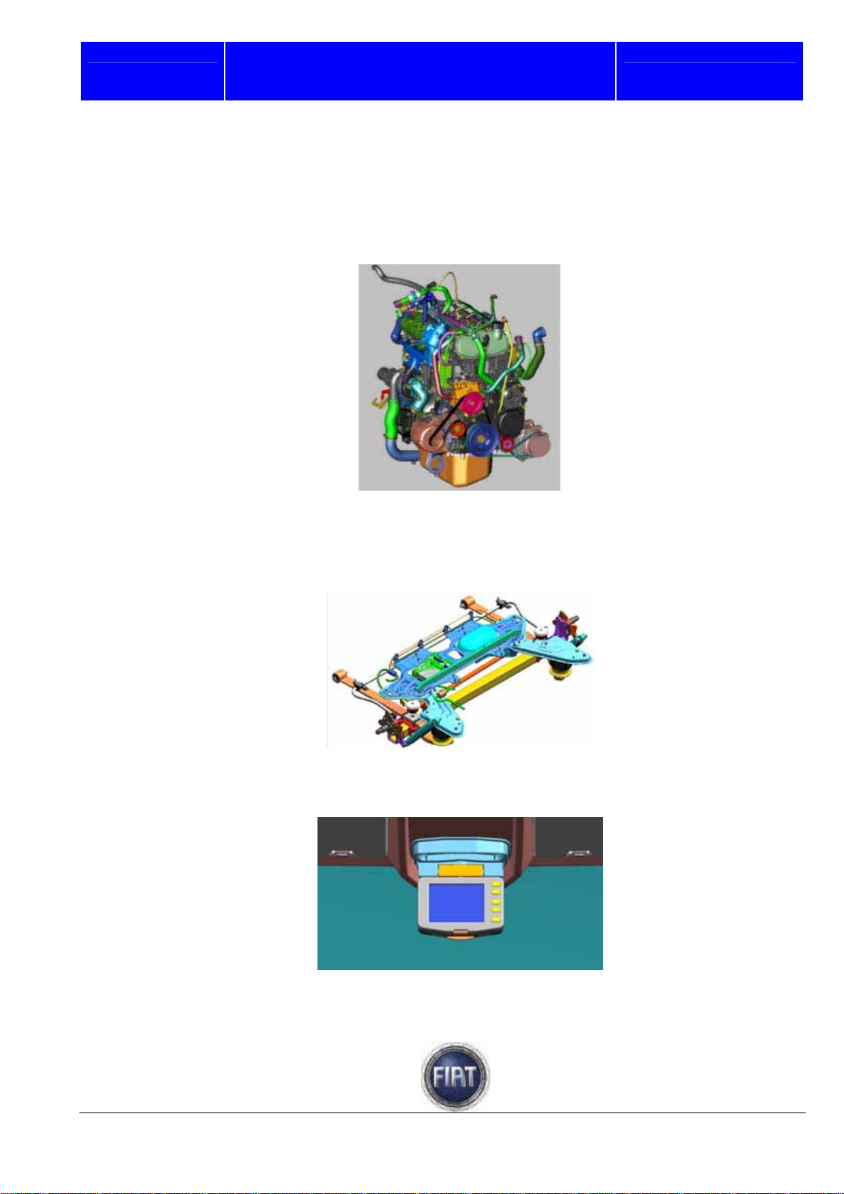
The range of engine versions is complemented by the 157 bhp 3.0 Multijet engine combined with the new
M40 gearbox.
FIAT DUCATO COURSE OUTLINE
Training Academy
The new self-levelling rear air suspension offers great comfort and consistent chassis attitude under all
loading conditions (vehicle laden or unladen, load distributed evenly or unevenly). In addition, the rear
loading sill can be lowered to facilitate loading and unloading and the rear end can be raised to improve
ramp breakover angle and/or increase ground clearance when driving over an obstacle.
The new rear-view parking camera system with in-cab display provides better rear visibility when
manoeuvring.
5/182
© 2006 Fiat Auto S.p.A. - All rights reserved
Page 6
Fiat Auto S.p.A.
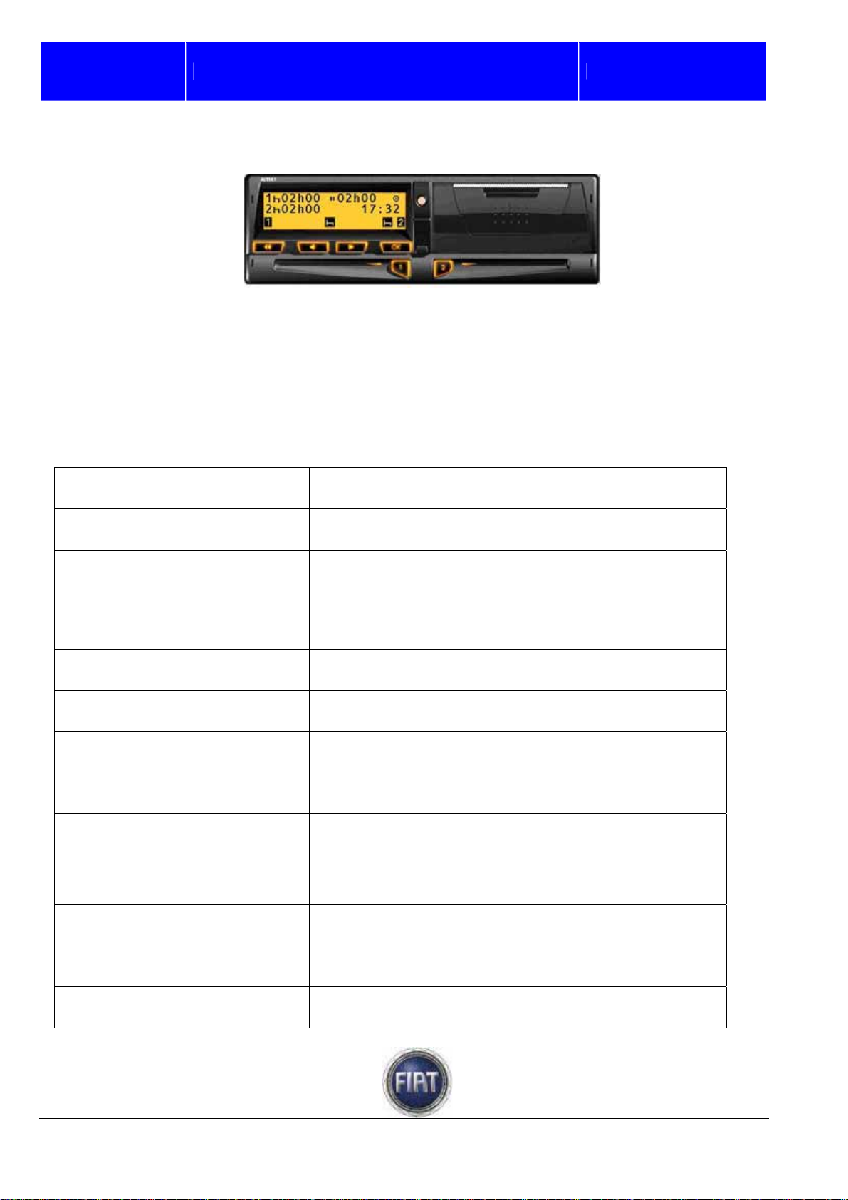
Lastly, the new Ducato can be equipped with a digital tachograph to monitor vehicle usage, a convenient
feature for companies that operate large fleets of vehicles
2. TECHNICAL DATA
2.1 ENGINE
2.1.1 Characteristic data
Type code
FIAT DUCATO COURSE OUTLINE
SofimF1CE048ID
Training Academy
Cycle
Number and arrangement of
cylinders
Piston diameter and stroke
(mm)
Total displacement
(cm3)
Compression ratio
Maximum power output
EEC(kW)
Maximum power output
EEC(bhp)
At
(rpm)
Maximum torque (EEC)
(Nm)
At
(rpm)
Diesel
4 in-line
95.8x10⁴
2999
19:1
117
157
3500
400
1600
Fuel
Fuel system
© 2006 Fiat Auto S.p.A. - All rights reserved
Diesel fuel (ENS 590 Specification)
Multijet” Common Rail” direct injection
6/182
Page 7
Fiat Auto S.p.A.
2.2 CLUTCH
Type Dry single-plate, pressure plate with automatic play take-
Drive
FIAT DUCATO COURSE OUTLINE
up device
Push-type
Training Academy
Outer diameter of driven
plate (mm)
Inner diameter of driven
plate (mm)
2.3 GEARBOX
Type
Gear ratios
(*) Different versions
2.4 DIFFERENTIAL
Axle ratio
258±1
160±5
C546 (M40)
I
II
III
IV
V
VI
RM
3.950 - 4.222 - 4.563 (*)
4.167
2.350
1.462
1.047
0.955(*)
0.786
0.659(*)
0.652
0.552(*)
4.083
(*) Different versions
7/182
© 2006 Fiat Auto S.p.A. - All rights reserved
Page 8

Fiat Auto S.p.A.
FIAT DUCATO COURSE OUTLINE
2.5 SCHEDULED MAINTENANCE PLAN
Description
Training Academy
Check tyre condition / check for wear,
adjust tyre pressure (if needed).
Check operation of lighting system
(headlamps, indicators, emergency lights,
luggage compartment/passenger & driver
compartment lights; instrument panel
warning lights, etc.).
Check operation of windscreen wiper &
washer; adjust nozzles if necessary.
Check positioning/wear of windscreen
wipers
Check brake pads for wear; check front
and rear disk pad wear indicator for proper
operation (if fitted)
Visually inspect the conditions and
soundness of body outside, underbody
protection, rigid and flexible pipe lengths
(exhaust, fuel feed and brake pipes and
hoses), rubber parts (boots, sleeves,
bushes, etc.)
Visually inspect the accessory drive belts
45 90 135 180 225
+ + + + +
+ + + + +
+ + + + +
+ + + + +
+ + + + +
+ + + + +
+ +
Check the fluid levels (engine cooling,
brakes, windscreen washer, battery, etc.)
and top up, if necessary
Check the handbrake lever travel and
adjust as required
Check that the locks are clean and the
levers clean/lubricated
Measure exhaust emissions/smoke
Check operation of engine control systems
(via the diagnostic connector)
Replace the accessory drive belt
Change fuel filter
Change air filter cartridge
© 2006 Fiat Auto S.p.A. - All rights reserved
+ + + + +
+ + + + +
+ + + + +
+ + + + +
+ + + + +
+
+ + + + +
+ + + + +
8/182
Page 9

Fiat Auto S.p.A.
Change engine oil and engine oil filter
FIAT DUCATO COURSE OUTLINE
+ + + + +
Training Academy
Change brake fluid (or every 24 months)
Change pollen filter (or every 24 months)
Service must be performed every 30000 km if the vehicle is chiefly used in any of the following particularly
harsh conditions:
Towing trailer or caravan;
Dusty roads;
Frequent short trips (less than 7-8 km) with outside temperatures below freezing;
Engine frequently left idling or running long distances at low speed (door-to-door delivery for example),
or if not used for a long time;
City traffic.
+ +
+ + + + +
9/182
© 2006 Fiat Auto S.p.A. - All rights reserved
Page 10
Fiat Auto S.p.A.
3. ENGINE
3.1 3.0 ENGINE
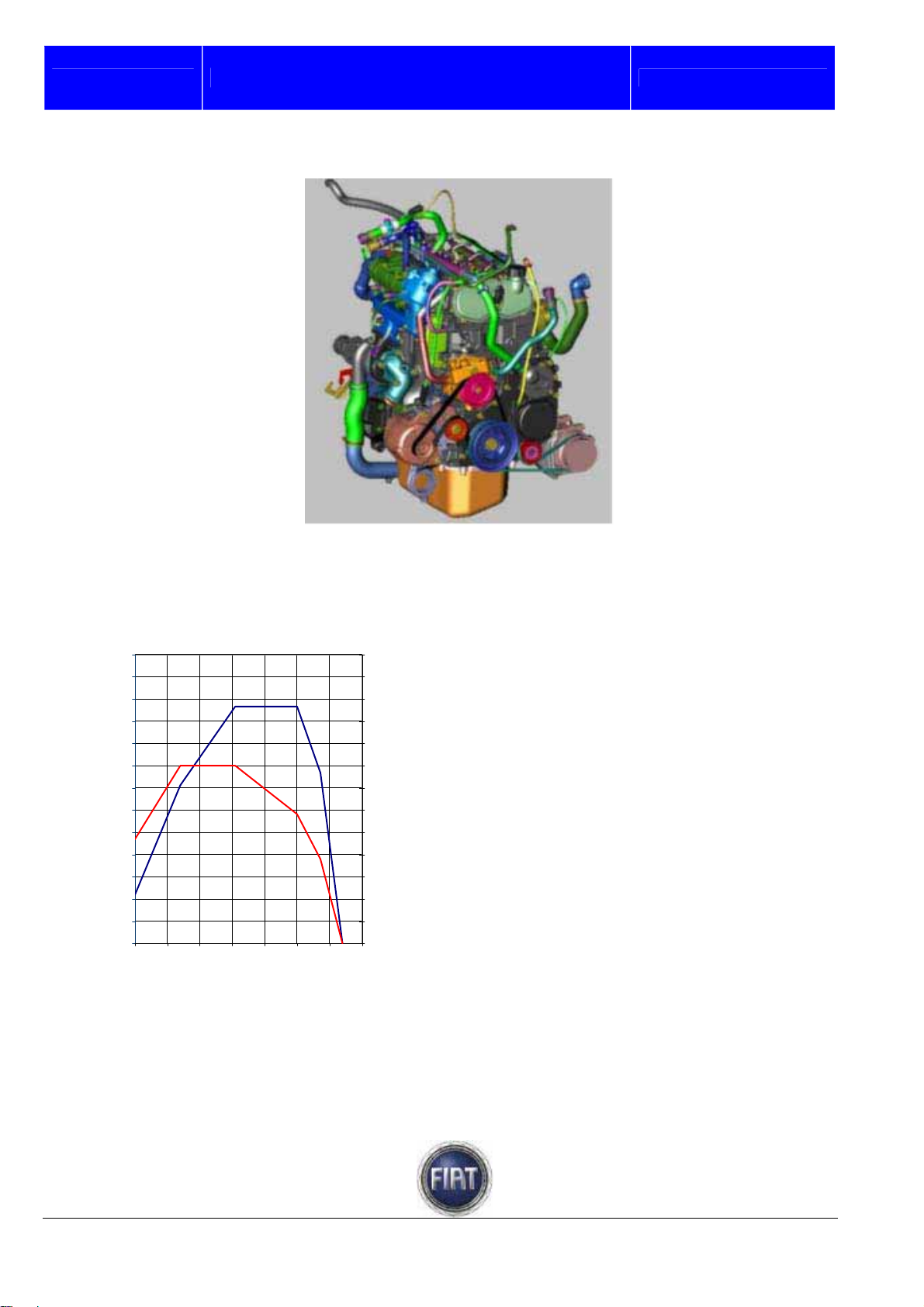
3.1.1 Features
The main features of the 3.0 Multijet engine
are as follows:
130
120
110
100
90
80
70
60
Power [kW]
50
40
30
20
10
0
1000 1500 2000 2500 3000 3500 4000 4500
FIAT DUCATO COURSE OUTLINE
F1C 107 kW [145 HP] - 400 Nm
WG
[rpm]
650
600
550
500
450
400
350
300
250
200
150
100
50
0
Training Academy
- turbocharged Diesel engine with fixed
geometry turbocharger;
- Euro 4 emissions compliant
- power output: 160 bhp;
- four cylinders in line;
- 2998 cc displacement;
- bore: 95.8 mm;
- stroke: 104 mm;
- compression ratio: 19:1
- firing order: 1 – 3 – 4 - 2
- double overhead camshaft, 16 valves;
- aluminium alloy cylinder head;
- camshaft bearing housings incorporated in
Torque [Nm]
upper head section;
- chain-driven timing system;
- rocker arms with hydraulic tappets;
- centrifugal water pump incorporated in
crankcase;
- engine control unit: Bosch EDC16C39;
- high-pressure pump: Bosch CP3.2 (no
transfer gear pump);
- nodular cast iron engine block;
- pressed sheet metal oil sump.
© 2006 Fiat Auto S.p.A. - All rights reserved
10/182
Page 11
Fiat Auto S.p.A.
FIAT DUCATO COURSE OUTLINE
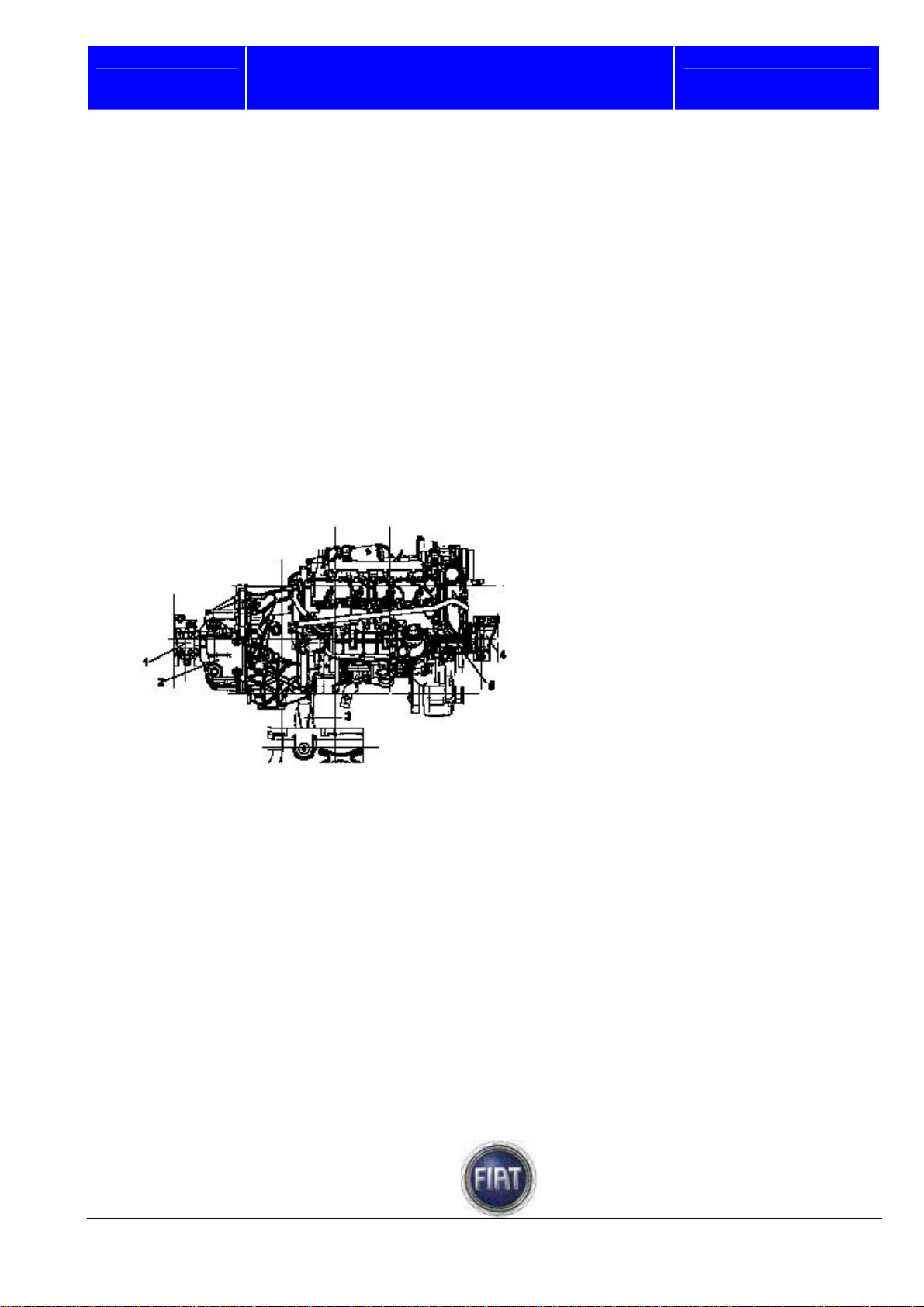
3.1.2 Engine mounts
GENERAL
The engine mounts connect engine and body.
They are designed to withstand engine weight and torque loads.
Engine mounts feature blocks made of metal and rubber that dampen engine vibration so as to
significantly reduce the amount of vibration transmitted to the body.
TYPE
The engine support system is a special baricentre system.
The engine is retained by two mounts (one on gearbox side and one on timing gear side) and a torque
linkage
.
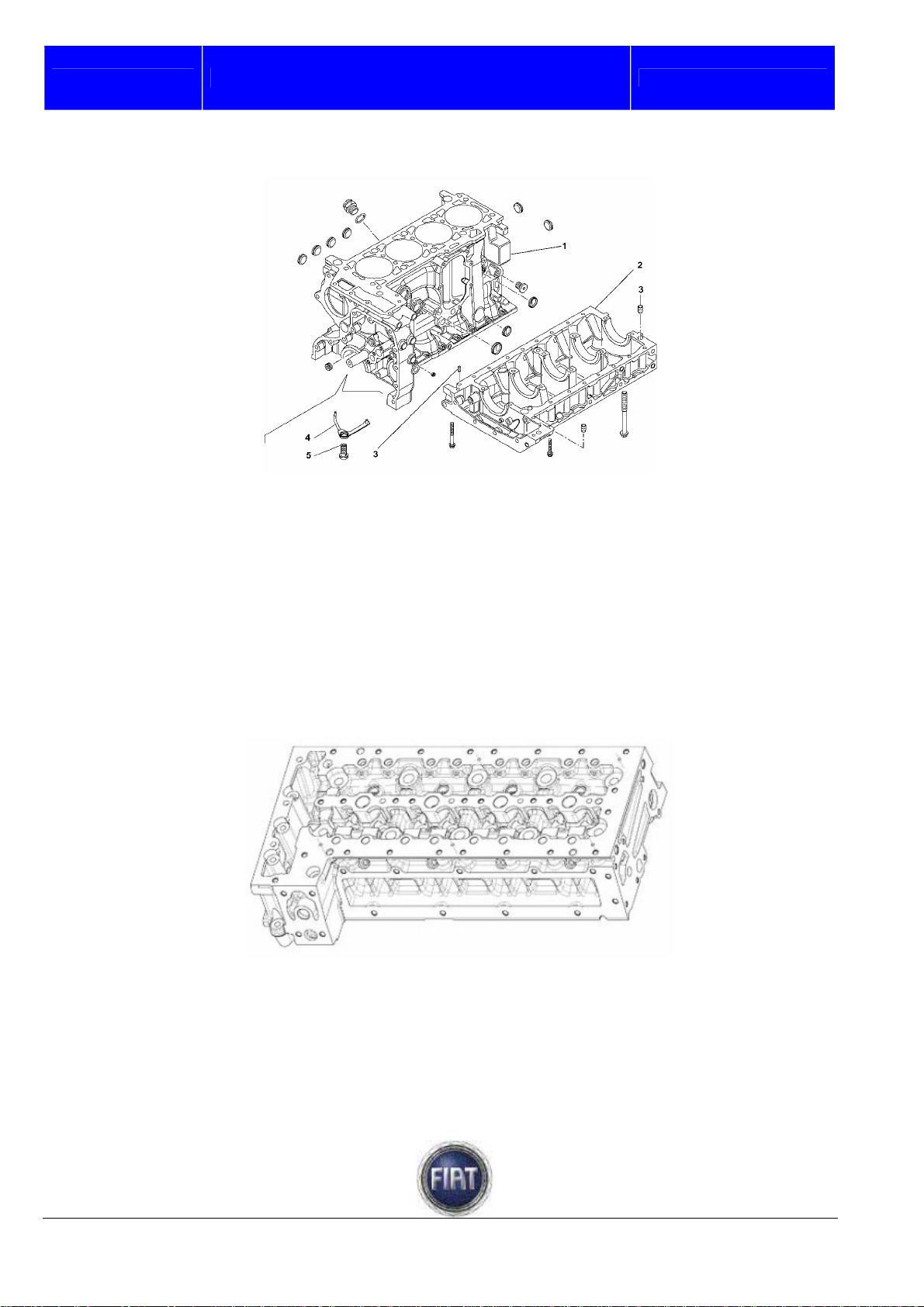
3.1.3 Crankcase and lower block
The crankcase is made of cast iron.
There are five main bearing housings.
Suitable coolant and oil galleries are provided in the crankcase walls.
Spray jets installed in crankcase bottom use engine oil to cool the pistons and lubricate the piston pins.
Crankcase and lower block are sealed with sealant.
Training Academy
1 – Flexible mount, gearbox side
2 – Mounting bracket, gearbox side
3 – Rear mounting bracket
4 – Flexible mount, timing gear side
5 – Mounting bracket, timing gear side
11/182
© 2006 Fiat Auto S.p.A. - All rights reserved
Page 12
Fiat Auto S.p.A.
FIAT DUCATO COURSE OUTLINE
1 - Crankcase
2 – Lower block
3 – Centring pin
4 – Piston cooling jet
5 – Jet connector
3.1.4 Cylinder head
The one-piece cylinder head is made from aluminium-silicon alloy.
Training Academy
Valve opening is controlled by two chain-driven hollow-section overhead camshafts; cams are fitted onto
the shafts; camshafts are installed in the upper head section.
The four valves per cylinder are located in their respective guides and operated by rocker arms actuated
by the cams of the camshafts; hydraulic tappets keep the rocker arms in contact with the valves.
© 2006 Fiat Auto S.p.A. - All rights reserved
12/182
Page 13
Fiat Auto S.p.A.
FIAT DUCATO COURSE OUTLINE
Training Academy
The valve guides are an interference fit in the seats in the cylinder head. The inner bore is bored to
specification after installation using a special boring tool.
Unlike cylinder heads with a prechamber, the whole combustion process occurs inside the combustion
chamber in the piston.
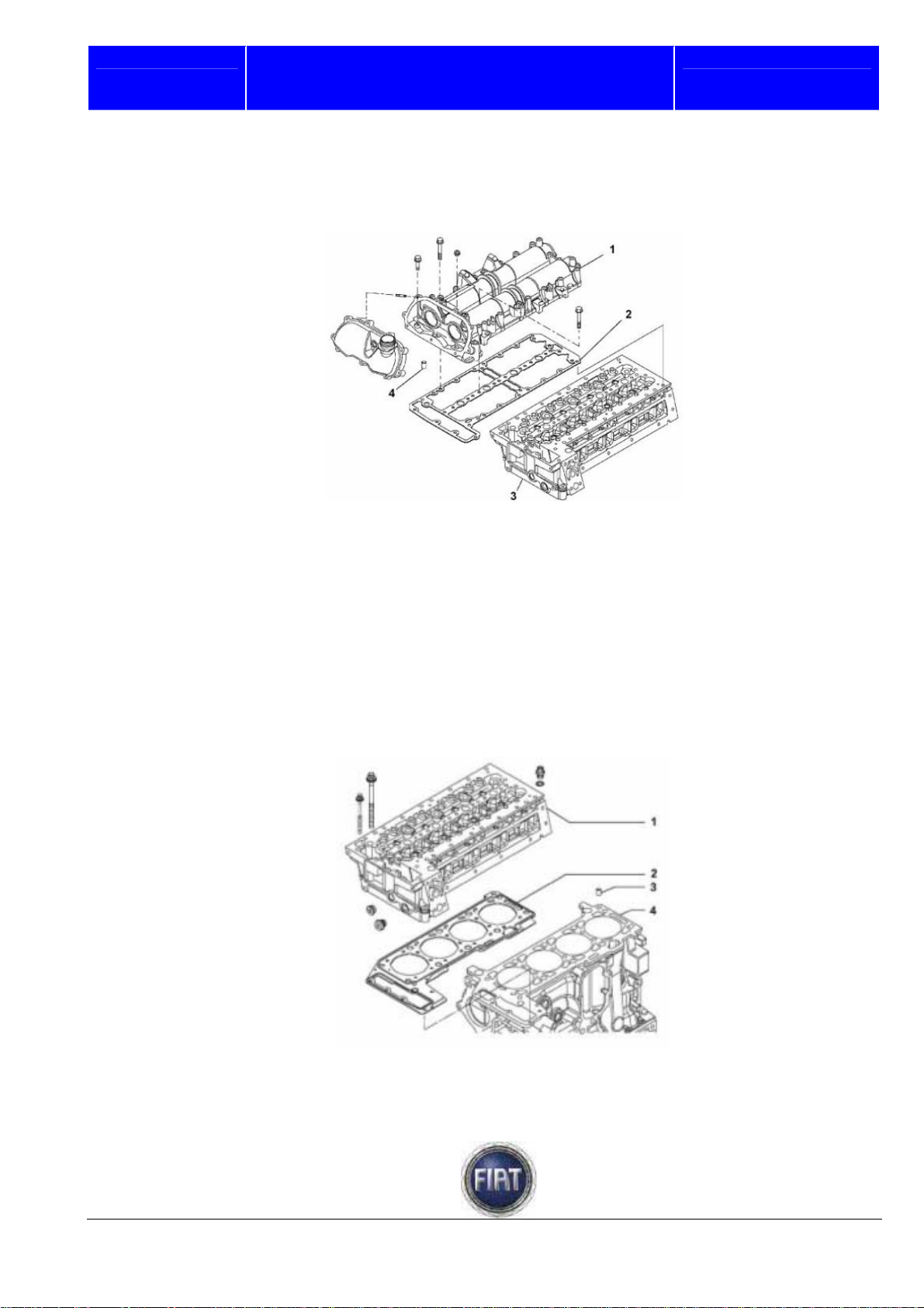
The cylinder head is made up of the following components:
- camshaft housing,
- hydraulic tappets, 1 – Upper head section
- rocker arms, 2 – Gasket
- camshafts, 3 – Cylinder head
- exhaust and intake valves, 4 – Centring bushes
- valve guides,
- valve seats.
1 – Cylinder head
2 – Gasket
3 – Centring bush
4 – Engine block
13/182
© 2006 Fiat Auto S.p.A. - All rights reserved
Page 14
Fiat auto S.p.A.
The head accommodates: intake ports; exhaust ports; valve passages; coolant galleries; oil galleries;
injector holes, glow plug holes, bolt holes for fastening to the engine block.
The head is installed on top of the cylinders; the aluminium alloy construction combines such advantages
as ligthweight, compression strength and high heat conduction.
Two centring bushes ensure correct location of the upper head section.
Head gasket
The gasket between cylinder head and crankcase is composed of three layers of stainless steel coated
with special heat-resistant rubber material.
While head gaskets of three different thicknesses are used at the factory, replacement gaskets come in
one standard thickness only. Factory gaskets are differentiated by notches as follows
- 1 notch : thickness class 1
- 2 notches: thickness class 2
- 3 notches: thickness class 3
FIAT DUCATO COURSE OUTLINE
Training Academy
1 – Head gasket
2 – Thickness class notches
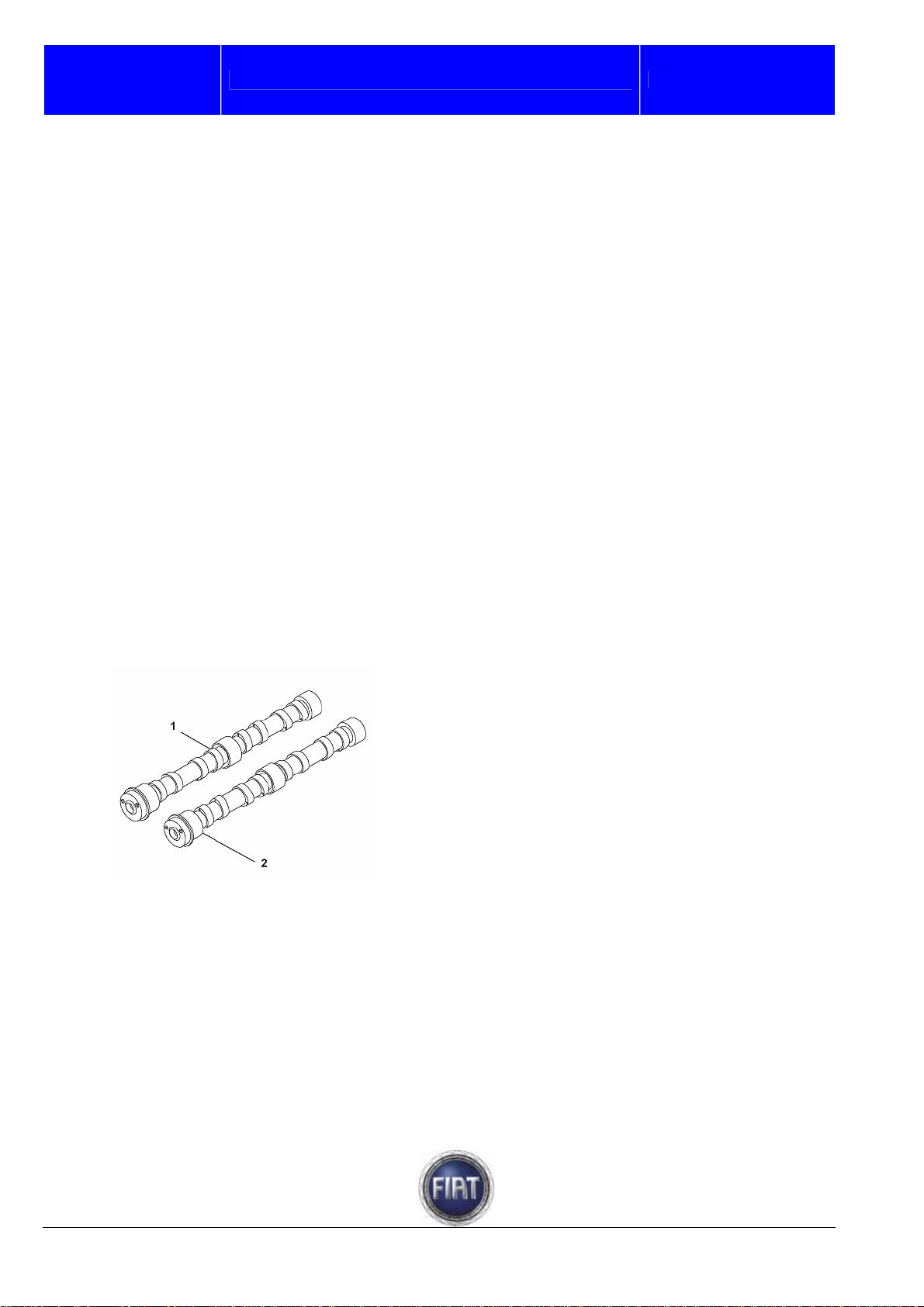
3.1.5 Camshafts
The timing sensor detects the position of the intake camshaft drive gear to determine the current phase
of engine operation.
The timing sensor is located on the engine oil filler cover on the upper head section.
The camshafts are made from steel and feature a
hollow design
1 – Exhaust camshaft
2 – Intake camshaft
© 2006 Fiat Auto S.p.A. - All rights reserved
14 / 182
Page 15
Fiat Auto S.p.A.
Hydraulic tappets
1
. Tappet retaining spring
2. Hydraulic tappet
3. Rocker arm with spring
4. Cam
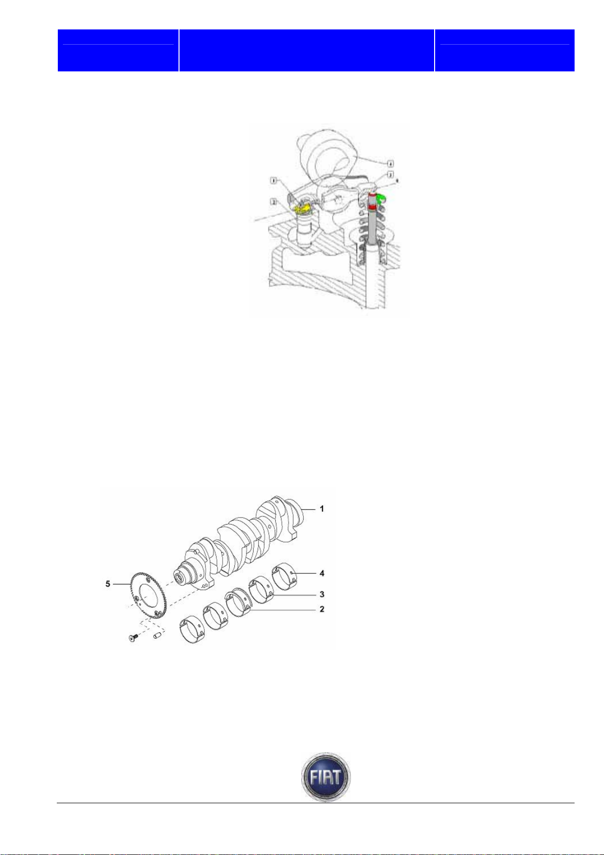
3.1.6 Crankshaft
The crankshaft is made of carbon steel and rests on five main bearing housings with plain bearings
in-between.
Crankshaft end float is determined by the half bearing housed at the central main bearing housing.
Eight counterweights set at 180° balance the rotating masses to provide perfect engine balance.
FIAT DUCATO COURSE OUTLINE
1 – Crankshaft
2 – Central main bearing (incorporates end
float adjustment)
3 – Main bearings
4 – Oilway hole
5. Phonic wheel
Training Academy
15 / 182
© 2006 Fiat Auto S.p.A. - All rights reserved
Page 16
Fiat auto S.p.A.
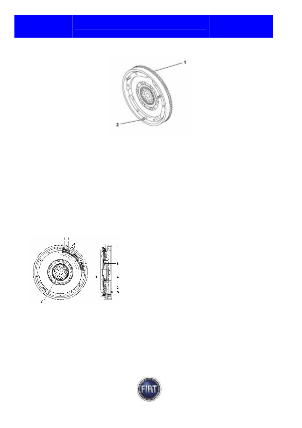
3.1.7 Flywheel
FIAT DUCATO COURSE OUTLINE
Training Academy
The dual-mass flywheel is secured to the crankshaft by 8 screws.
The flywheel has 3 centring pins for the clutch mechanism
The flywheel is an energy storage device that stores energy during the power stroke and gives up energy
during the combustion stroke to smooth out engine rotation.
Flywheel size is designed to enable engine idling and overcome friction developed during idling.The DVA
dual-mass flywheel (or clutch flywheel) consists of two separate masses for crankshaft and gearbox main
shaft with a torsional damping system in-between.
Resonance points, normally found in the 800 to 2200 rpm range with conventional flywheels, occur at lower
rpms, namely outside the operating range.
This flywheel design offers the following advantages over conventional flywheels:
- pulsing engine power is dampened resulting in less transmission noise;
- less overall noise translates into less in-cab noise.
The clutch disk (with springs) located between the dual-mass flywheel and the gearbox has lower inertia
to enable smoother gearshifts.
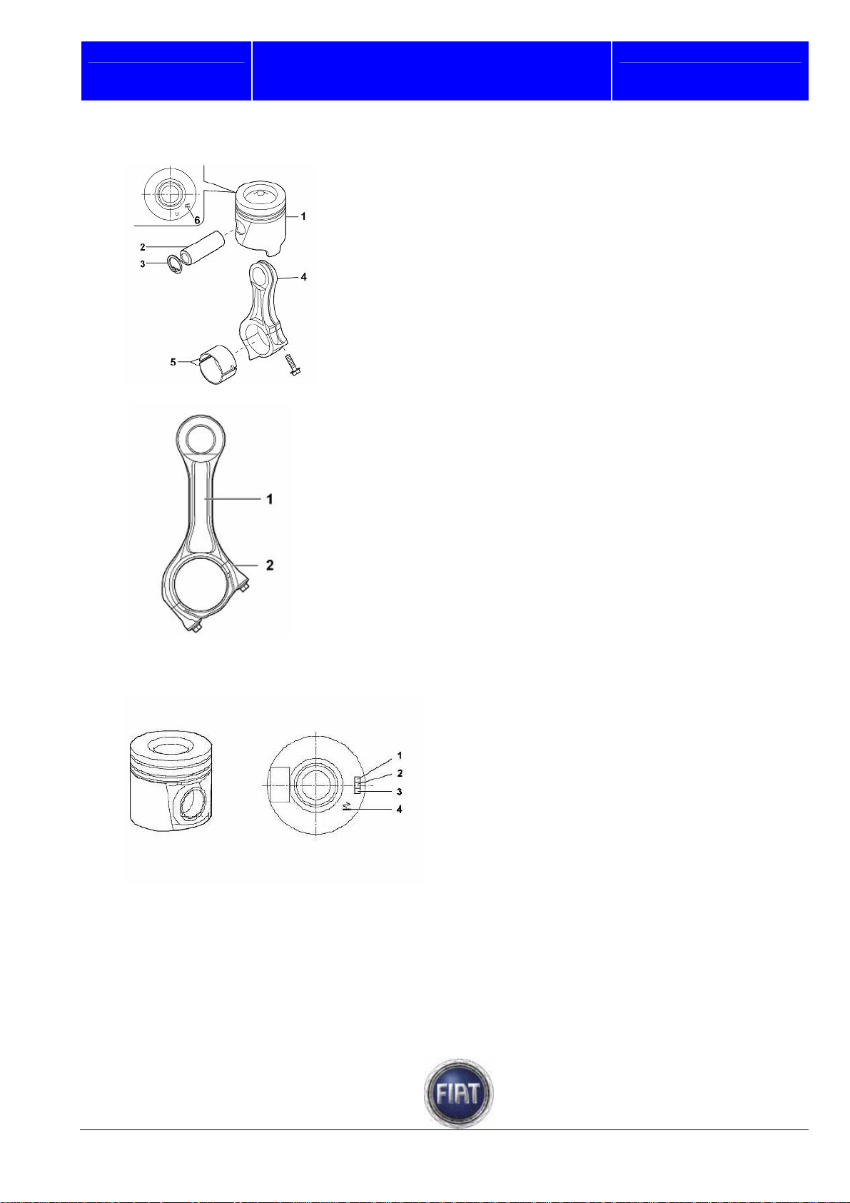
3.1.8 Pistons and connecting rods
CONSTRUCTION
The pistons are obtained from aluminium alloy castings; the connecting rods are forged from hardened
and tempered steel and split to obtain the con rod caps by the fracture splitting method.
The pistons have a recess for the combustion chamber.
The pistons and con rod small ends are joined by floating piston pins. Piston pins are restrained by two
circlips fitted in grooves in the piston pin sleeves.
1 – Mass integral with crankshaft.
2 – Mass integral with gearbox main shaft.
3 – Centring pin for clutch mechanism
4 – Hub
5 – Ball bearing
6 – Gearwheel
7 – Torsional damping system.
© 2006 Fiat Auto S.p.A. - All rights reserved
16 / 182
Page 17
Fiat Auto S.p.A.
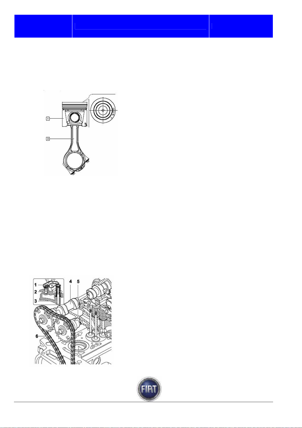
To ensure correct piston position, the mark on the piston must be pointing to the timing gear side
FIAT DUCATO COURSE OUTLINE
1 – Piston
2 – Piston pin
3 – Circlips
4 – Connecting rod
5 – Con rod bearings
6 – Piston mark for correct installation
1 – Connecting rod
2 – Con rod cap
The aluminium alloy pistons are grouped
into two size classes and have a mark on
the crown to indicate correct mounting
position
Training Academy
1 – Engine type
2 – Piston class
3 – Supplier
4 – Mounting position of piston inside the
cylinder barrel
The piston is made up of two main components:- head, or area where the piston rings sit; its diameter is
slightly smaller than the cylinder bore to accommodate heat expansion; the piston crown features the
valve pockets and recessed combustion chambers,
17 / 182
© 2006 Fiat Auto S.p.A. - All rights reserved
Page 18
Fiat auto S.p.A.
- the skirt, which acts as a guide for the con rod small end which withstands its axial thrust. The skirt
accommodates two sleeves for the piston pin and a groove matching the piston cooling jet in the
crankcase.
FIAT DUCATO COURSE OUTLINE
Piston (1) and connecting rod (2) with con
rod cap must be assembled with piston
mark, connecting rod and con rod
positioned as shown in the figure.
Training Academy
3.1.9 Camshaft drive
The timing system is a double overhead camshaft system with four valves per cylinder and hydraulic
tappets.
Drive is transmitted by two drive chains:
- a double 3/8” chain transmits drive from the crankshaft to the oil pump/vacuum pump and high pressure
pump shafts;
- a single chain transmits drive from the high pressure pump shaft to the camshafts.
The camshaft drive gears are interchangeable and feature slots for the sensor.
Each rocker arm is kept in contact with its valve by a cam and hydraulic tappet to eliminate the need for
periodic adjustments
.
1 – Rocker arm
2 – Hydraulic tappet
3 – Valve
4 – Exhaust camshaft
5 – Intake camshaft
6 – Cam chain
© 2006 Fiat Auto S.p.A. - All rights reserved
18 / 182
Page 19
Fiat Auto S.p.A.
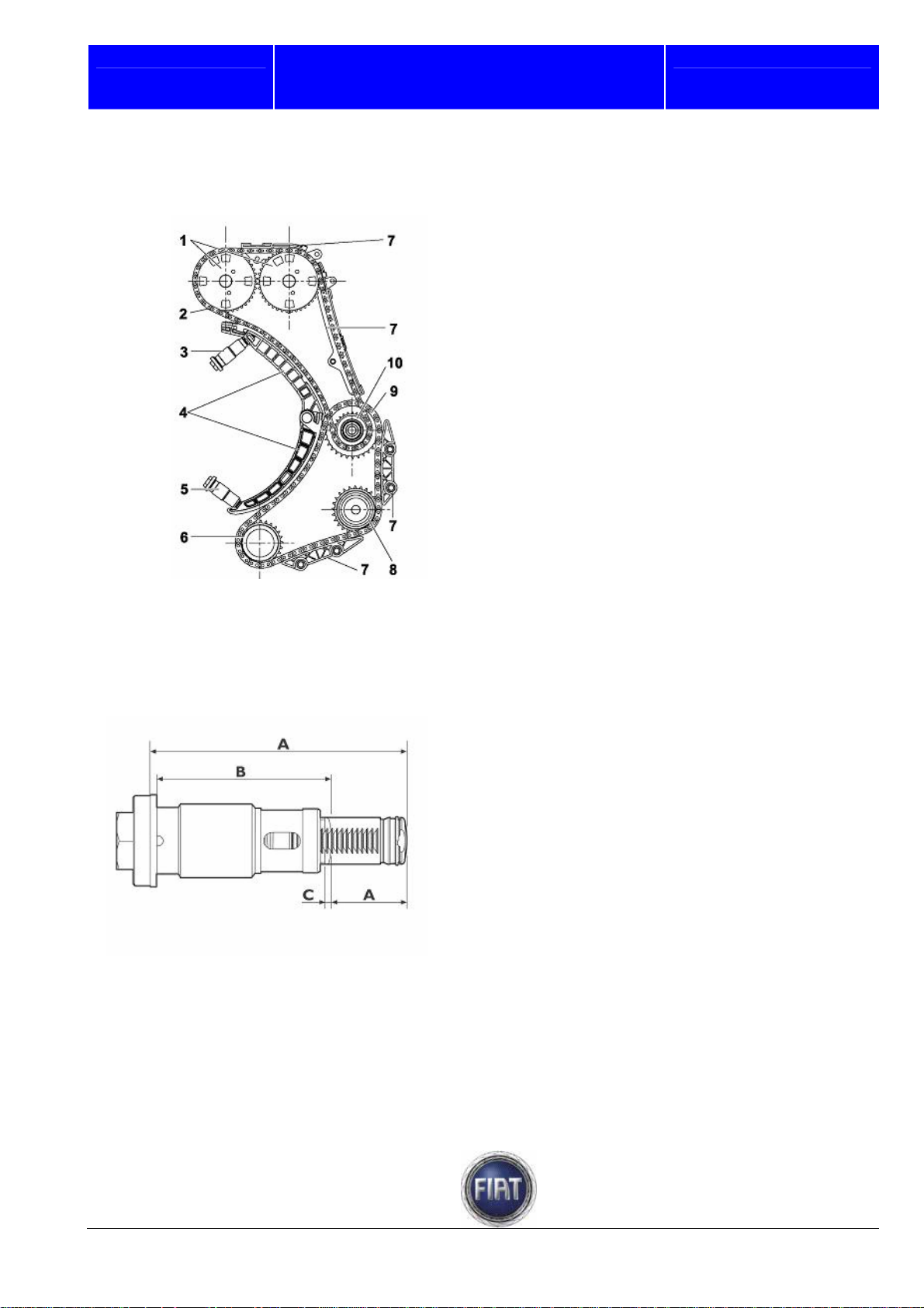
The figure below shows how timing system and auxiliary drive system are operated
FIAT DUCATO COURSE OUTLINE
1 – Camshaft drive gears
2 – Single chain
3 – Hydraulic tensioner with backstop
4 – Chain tensioner mobile sliding shoes
5 – Hydraulic chain tensioner
6 – Drive gear on crankshaft
7 – Fixed sliding shoe
8 – Oil pump/vacuum pump and power
steering pump drive shaft gear
9 – Double chain
10 – High pressure pump drive shaft gear
Training Academy
Chain hydraulic tensioner
Timing chain tension is controlled by an automatic hydraulic tensioner with backstop that eliminates the
need for tension adjustments.
A = Fully extended: 76.9 ± 0.4 mm
B = With piston engaged: 53.6 mm
C = Minimum travel to disengage piston:
2.3 mm
D = Useful stroke: 24.5 mm
19 / 182
© 2006 Fiat Auto S.p.A. - All rights reserved
Page 20
Fiat auto S.p.A.
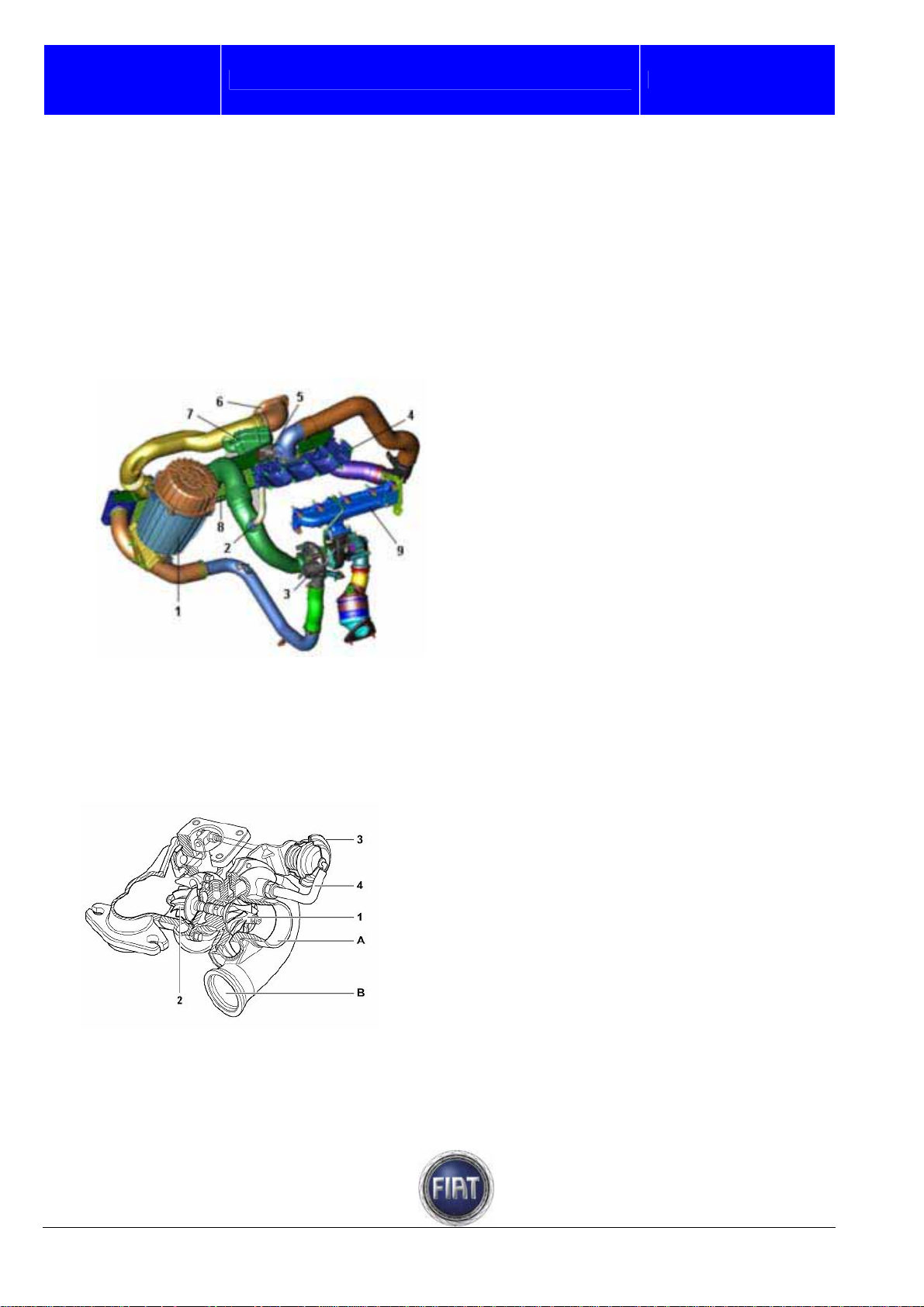
3.1.10 Air supply system
The intake air is filtered and conveyed to the exhaust gas turbocharger; before reaching the engine, the
compressed air is cooled in the air-air heat exchanger (Intercooler).
The following figure schematically illustrates the main elements comprising the air supply circuit.
FIAT DUCATO COURSE OUTLINE
1 – Air filter
2 – Oil vapour recovery fitting
3 – Turbocharger
4 – Intake manifold
5 – Throttle body actuator
6 – Air intake connector
7 – Resonator
8 – Intercooler heat exchanger
9 – Exhaust manifold
Training Academy
Turbocharger
The turbocharger is of the fixed geometry type with waste-gate valve
1 – Compressor
2 – Turbine
3 – Air-operated exhaust gas bypass actuator
4 – Pressure pipe to control WASTE – GATE
valve
A – Air enters compressor
B – Air exits compressor
© 2006 Fiat Auto S.p.A. - All rights reserved
20 / 182
Page 21
Fiat Auto S.p.A.
3.1.11 Fuel system
GENERAL
The fuel feed system is divided into a low pressure circuit and a high pressure circuit.
The low pressure circuit is composed of:
- tank
- submerged auxiliary motor pump;
- Diesel fuel filter;
- return manifold.
The high pressure circuit is composed of:
- pressure pump;
- distribution manifold.
Low pressure circuit
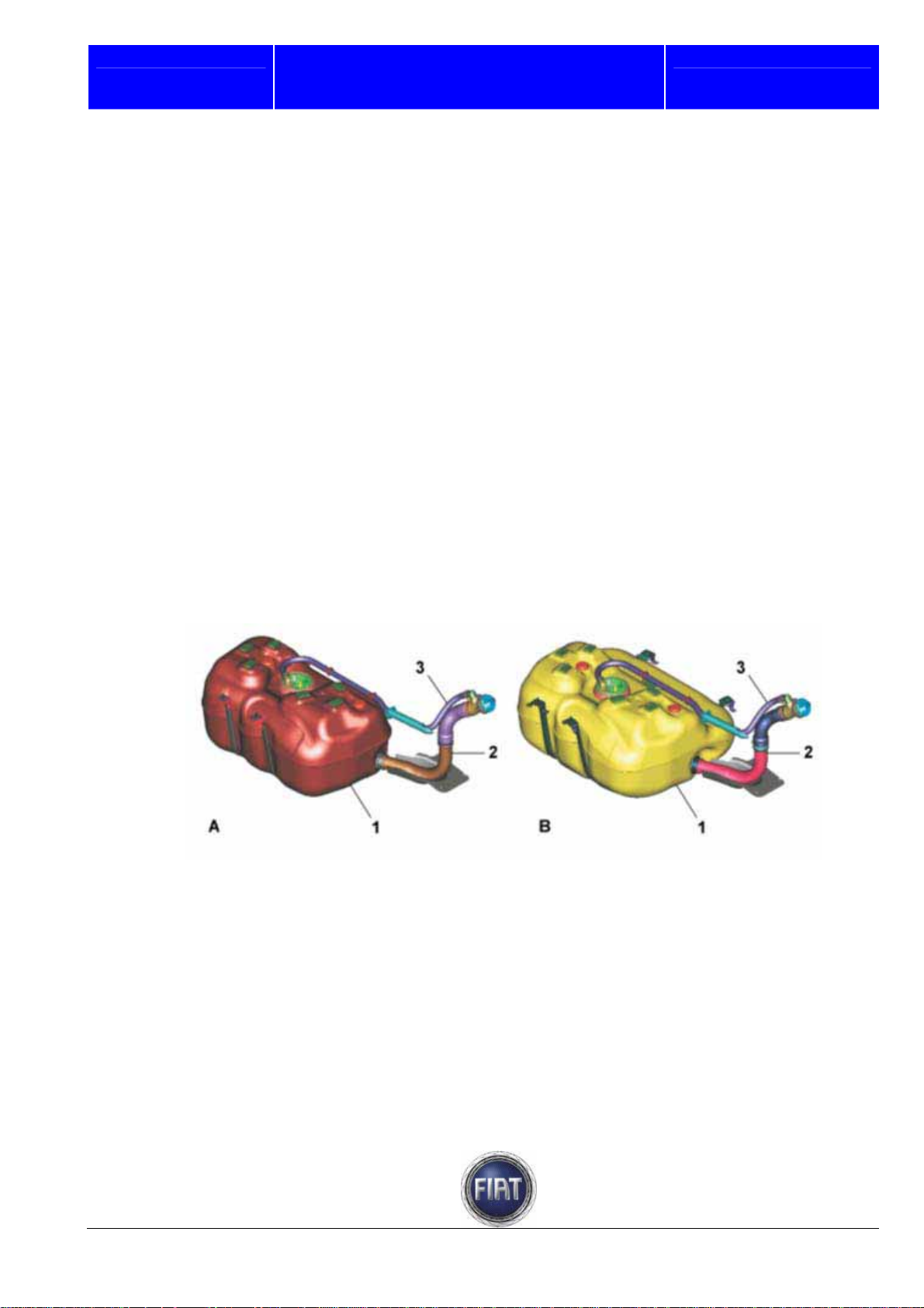
Fuel tank
The plastic fuel tank features a flexible filler neck and incorporates a seat for electric fuel pump and fuel
level meter.
FIAT DUCATO COURSE OUTLINE
Training Academy
A – 90-litre tank
B – 125-litre tank
1 – Fuel tank
2 – Fuel filler neck
3 – Breather pipe
21 / 182
© 2006 Fiat Auto S.p.A. - All rights reserved
Page 22

Fiat auto S.p.A.
FIAT DUCATO COURSE OUTLINE
Submerged pump assembly complete with level indicator control system
- electric fuel pump
- float level indicator
- diaphragm pressure regulator
- screen prefilter
Main components:
- fuel filter
Pump characteristic data:
- safety valve setting: 600 - 800 KPa,
- pump nominal delivery: 134 l/h (23°C),
- power supply: 12.5V.
Training Academy
A – Float level sensor
B – Delivery fitting
B – Return fitting
D – Electric connector
1 – Fuel level sensor power supply
2 – Fuel level sensor ground
3 – Fuel pump ground
4 – Fuel pump power supply
© 2006 Fiat Auto S.p.A. - All rights reserved
22 / 182
Page 23
Fiat Auto S.p.A.
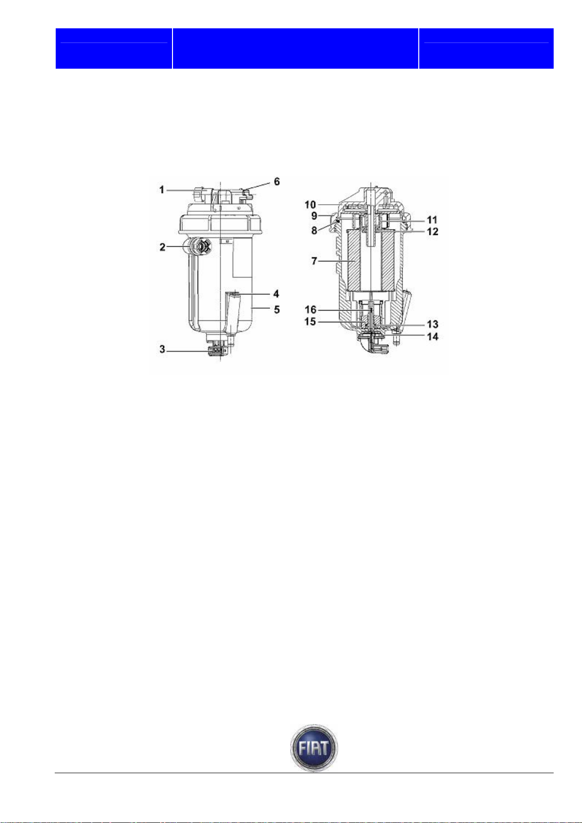
Fuel filter
The fuel filter is fitted in the engine compartment near the fireproof bulkhead.
The filter is made of a plastic shell that contains a depth partition cartridge made of synthetic material,
which ensures high efficiency, long service life and effective water separation.
1 – Fuel inlet
2 – Fuel outlet
3 – Eectric connector for water presence
sensor
4 – Water drain screw
5 – Filter body
6 – Fuel temperature sensor connector
7 – Filter cartridge (sealing O-ring supplied)
8 – Cover gasket
FIAT DUCATO COURSE OUTLINE
9 – Cover fixing ring nut
10 – Cover
11 – Spacer
12 – Rubber seal
13 – Ferromagnetic ring
14 – Gasket
15 – Float
16 – Water sensor
Training Academy
23 / 182
© 2006 Fiat Auto S.p.A. - All rights reserved
Page 24
Fiat auto S.p.A.
FIAT DUCATO COURSE OUTLINE
Training Academy
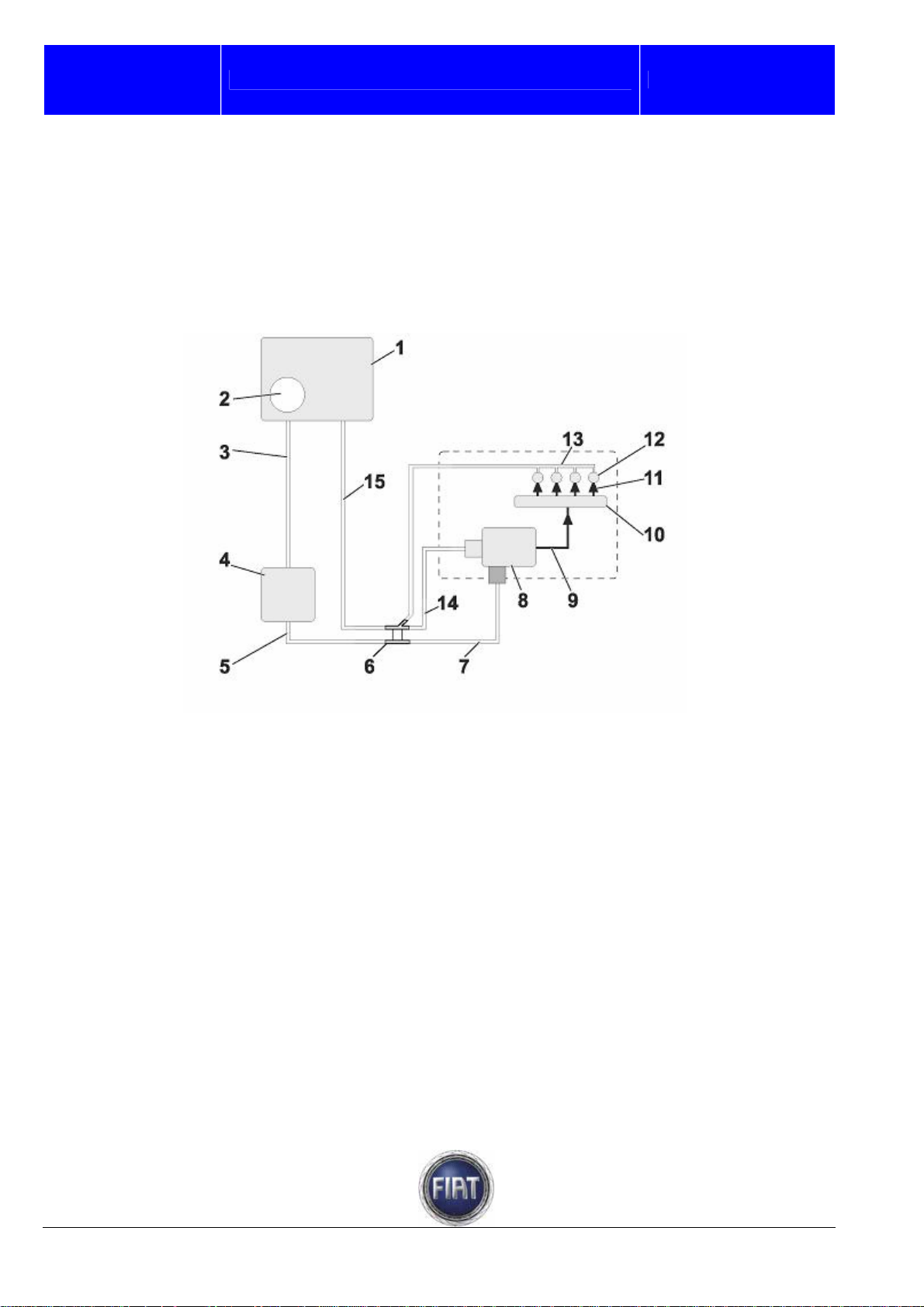
OPERATION
Diesel fuel is drawn from the tank by a 12 V electric pre-feed pump that provides adequate delivery to
lubricate and cool the Radialjet pump as well.
The Diesel fuel filter is installed between the electric pump and the Radialjet pump.
High-pressure hydraulic lines are steel pipes with 2 mm inner diameter and 6 mm outer diameter.
The fuel recirculated from pump and injectors is collected in a single pipe and delivered to the tank.
1 – Fuel tank
2 – Submerged pump assembly
3 – Pipe connecting tank with fuel filter
4 – Fuel filter
5 – Pipe connecting fuel filter with fuel pressure control valve
6 – Fuel pipe fitting
7 – Pipe connecting fuel pressure control valve with high pressure pump
© 2006 Fiat Auto S.p.A. - All rights reserved
24 / 182
Page 25
Fiat Auto S.p.A.
FIAT DUCATO COURSE OUTLINE
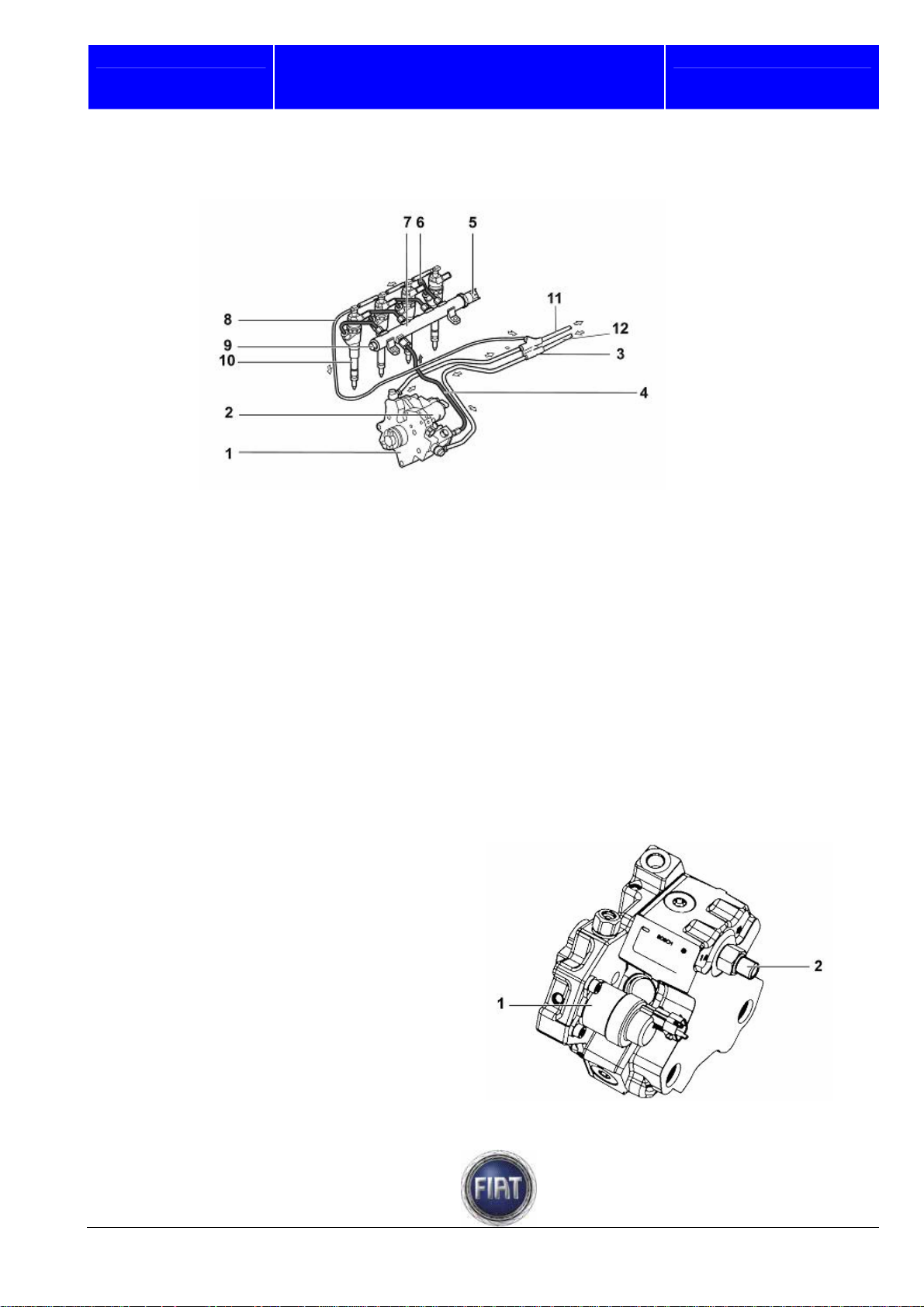
High pressure circuit
1 – Pressure pump
2 – Pressure regulator
3 – Fuel pipe fitting
4 – Pipe connecting high pressure pump with fuel manifold (Rail)
5 – Fuel pressure sensor
6 – Pipe connecting fuel manifold (Rail) with electro-injectors
7 – Fuel manifold (Rail)
8 – Return pipe from electro-injectors
9 – Plug
10 – Electro-injector
11 – Fuel pipe from filter
12 – Return to tank
High pressure pump
GENERAL’
The CP3.2 fuel pump of the Common Rail
system is called Radialjet pump because
pumping action is accomplished by three
pumping elements (pistons) arranged
radially in relation to the axis of rotation of
the pump shaft. The three pistons are
spaced 120° apart.
The quantity of fuel sent to the pumping
pistons is controlled by a pressure regulator
governed by the engine control unit
Training Academy
25 / 182
© 2006 Fiat Auto S.p.A. - All rights reserved
Page 26
Fiat auto S.p.A.
FIAT DUCATO COURSE OUTLINE
Training Academy
RADIALJET PUMP CHARACTERISTICS
Pump pistons are operated by a rotating triangular cam integral with pump shaft. The rotating cam moves
a mechanical element (tappet) linking it to piston foot. Cam to tappet contact is ensured by a spring.
Each pumping unit has an intake valve and delivery ball valve. Fuel from the three delivery valves is
collected in a single point inside the pump and conveyed to a common manifold through a single duct. A
peculiar feature of this pump is that it is lubricated and cooled by the fuel circulating inside it or through
suitable ports.
Delivery pressure is controlled by a low-pressure solenoid valve installed at the pump inlet end so as to
compress just the amount of fuel needed to achieve required pressure according to ECU mapping.
The main features of the Radialjet pump are outlined below:
- type: Radialjet radial piston pump
- number of pistons: 3
- maximum operating pressure: 1600 bar
- feeding: Diesel fuel at 3.5 ÷ 5.0 bar
- lubrication: by Diesel fuel fed to pump
- cooling: by Diesel fuel fed to pump
Note: The high pressure pump cannot be serviced; do not remove or disturb the retaining screws.
OPERATION
The pump is driven by the crankshaft via a double chain and turns at the same speed as the engine. In
this injection system, valve timing and injection duration are controlled by the electroni c control system
and the pump simply maintains the fuel in the manifold at the required pressure.
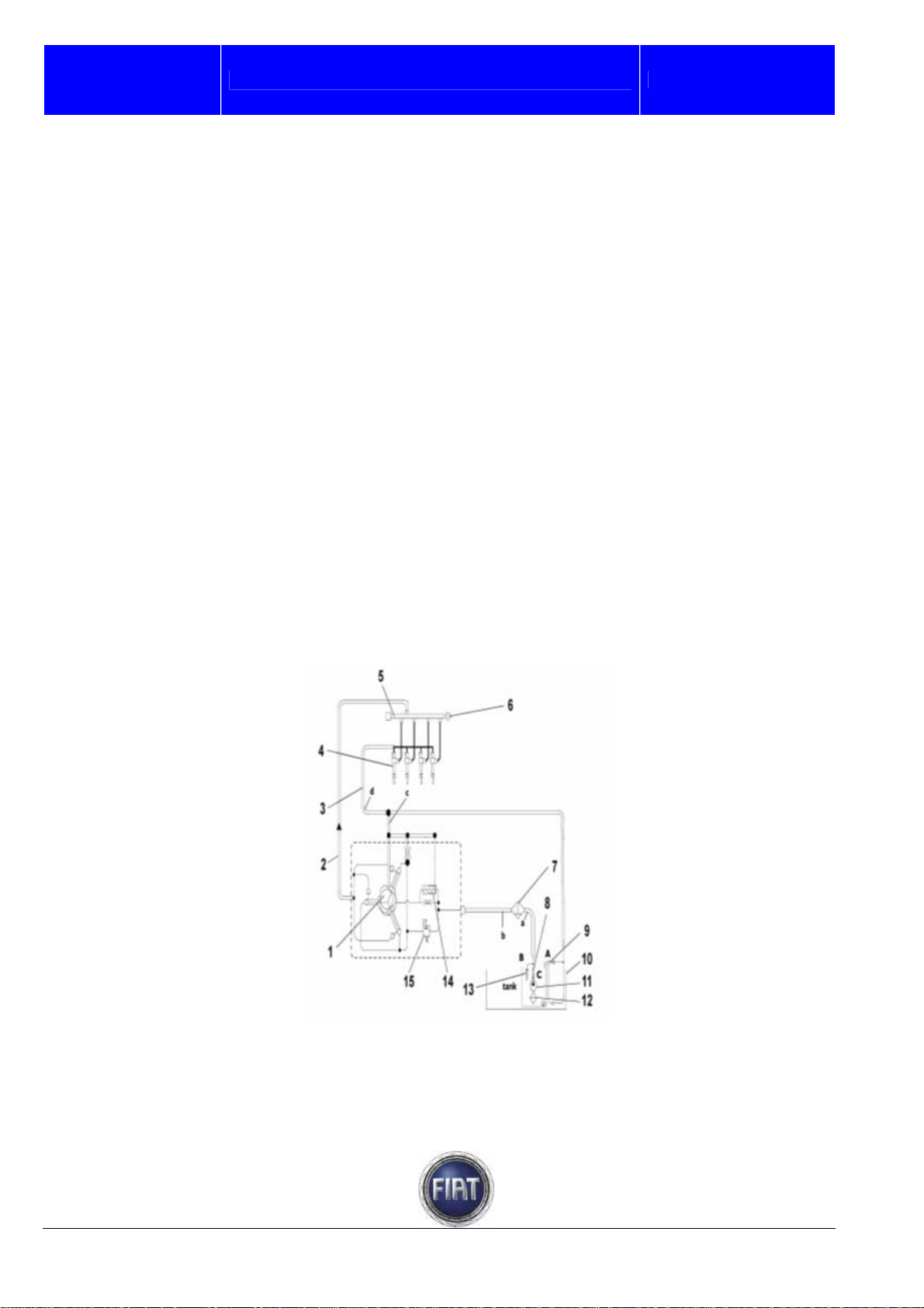
The figure below shows the layout of pump hydraulic feeding system.
© 2006 Fiat Auto S.p.A. - All rights reserved
26 / 182
Page 27
Fiat Auto S.p.A.
(Relative) pressures in the circuit:
(a) 4.15 bar < p < 5.35 bar ; (b) 3.5 bar < p < 5.0 bar ; (c) p < 0.8 bar (d) 0.3 bar < p < 0.8 bar
1 – High pressure pump
2 – High pressure delivery pipe
3 – Return pipe from electro-injectors
4 – Electro-injectors
5 – Common Rail
6 – Fuel pressure sensor
7 – Filter with water separator
8 – Electric fuel pump check valve
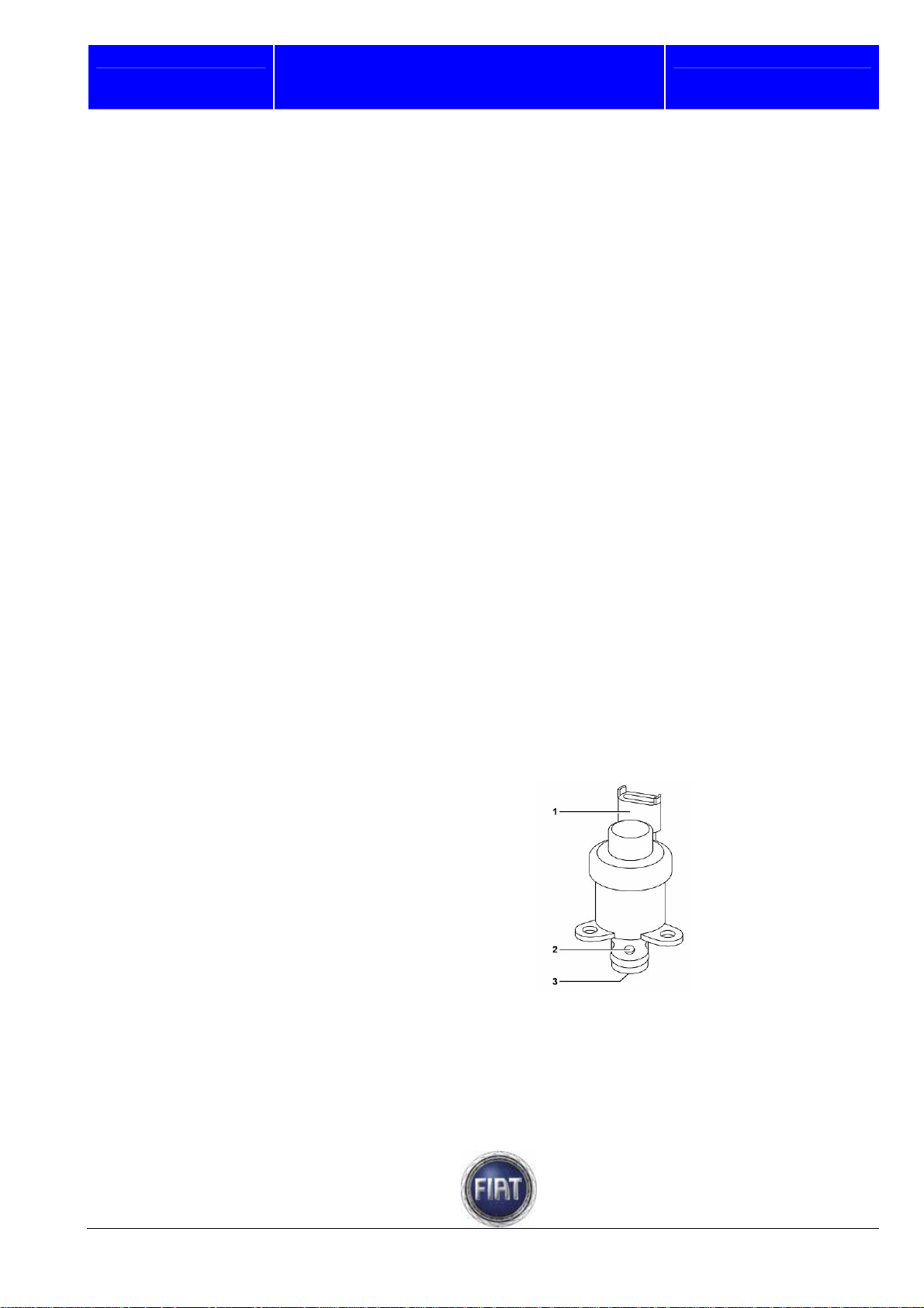
Fuel regulator
The fuel pressure regulator is installed in the low-pressure circuit of the CP3.2 pump.
The pressure regulator meters the amount of fuel delivered to the high-pressure circuit according to the
commands it receives directly from the engine control unit
The main components of the pressure regulator are listed below:
- connector,
- body,
- solenoid,
- preload spring,
- shutter cylinder.
The pressure regulator is normally open unless it is receiving any input signals; in this condition, the
pump will be delivering its maximum flow rate.
The engine control unit varies fuel delivery in the high-pressure circuit by partially closing or opening the
fuel pipe sections in the low pressure circuit via a PWM (Pulse Width Modulation) signal
1 – Connector
2 – Fuel outlet holes
3 – Fuel inlet hole
FIAT DUCATO COURSE OUTLINE
9 – Line pressure relief valve
10 – Tank
11 – Electric fuel pump
12 – Filter at electric fuel pump intake end
13 – Electric fuel pump overpressure valve
14 – Pressure relief valve
15 – Proportional pressure regulating
valve.
Training Academy
27 / 182
© 2006 Fiat Auto S.p.A. - All rights reserved
Page 28
Fiat auto S.p.A.
FIAT DUCATO COURSE OUTLINE
Training Academy
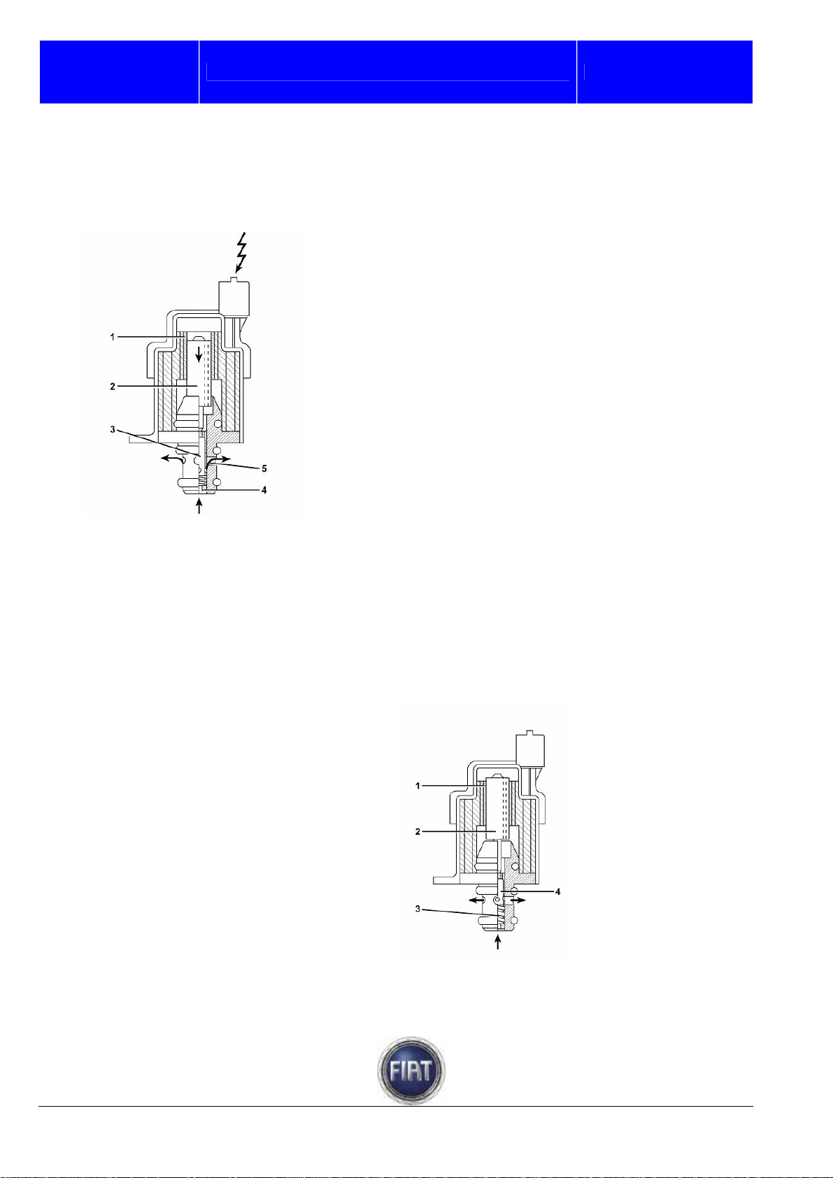
OPERATION
When the engine control unit governs the flow regulator (via PWM signal), the solenoid (1) is energised
and displaces the magnetic core (2).
The core causes the shutter cylinder (3) to move in an axial direction and fuel flow is restricted.
1 – Solenoid
2 – Magnetic core
3 – Shutter cylinder
4 – Fuel inlet
5 – Fuel outlet
When the solenoid (1) is de-energized, the magnetic core is pushed into its rest position by the preload
spring (3).
In this condition, the shutter cylinder (4) is in the position that provides a fully unrestricted fuel flow.
1 – Solenoid
2 – Magnetic core
3 – Preload spring
4 – Shutter cylinder
© 2006 Fiat Auto S.p.A. - All rights reserved
28 / 182
Page 29

Fiat Auto S.p.A.
Inertia switch
The inertia switch is located under the dashboard on passenger side. In the event of a collision, it cuts off
the fuel pump ground connection to shut off fuel delivery to the injection system.
It contains a ferromagnetic ball held in place in its tapered seat by a permanent magnet.
When vehicle deceleration exceeds a certain threshold due to a collision, the ball breaks free from its
seat and hits a switch, so that fuel pump relay ground is switched to the body computer.
This cuts off pump supply, releases the door locks and turns on the interior lighting.
The switch features a flexible cover to enable resetting.
NOTE: If you notice a burning smell or any leaks after an impact (including a minor collision), do no reset
the switch until you have located and repaired the trouble, or a fire may result. If there are no leaks and
the vehicle is capable of restarting, press the button to activate the fuel pump.
FIAT DUCATO COURSE OUTLINE
Training Academy
29 / 182
© 2006 Fiat Auto S.p.A. - All rights reserved
Page 30
Fiat auto S.p.A.
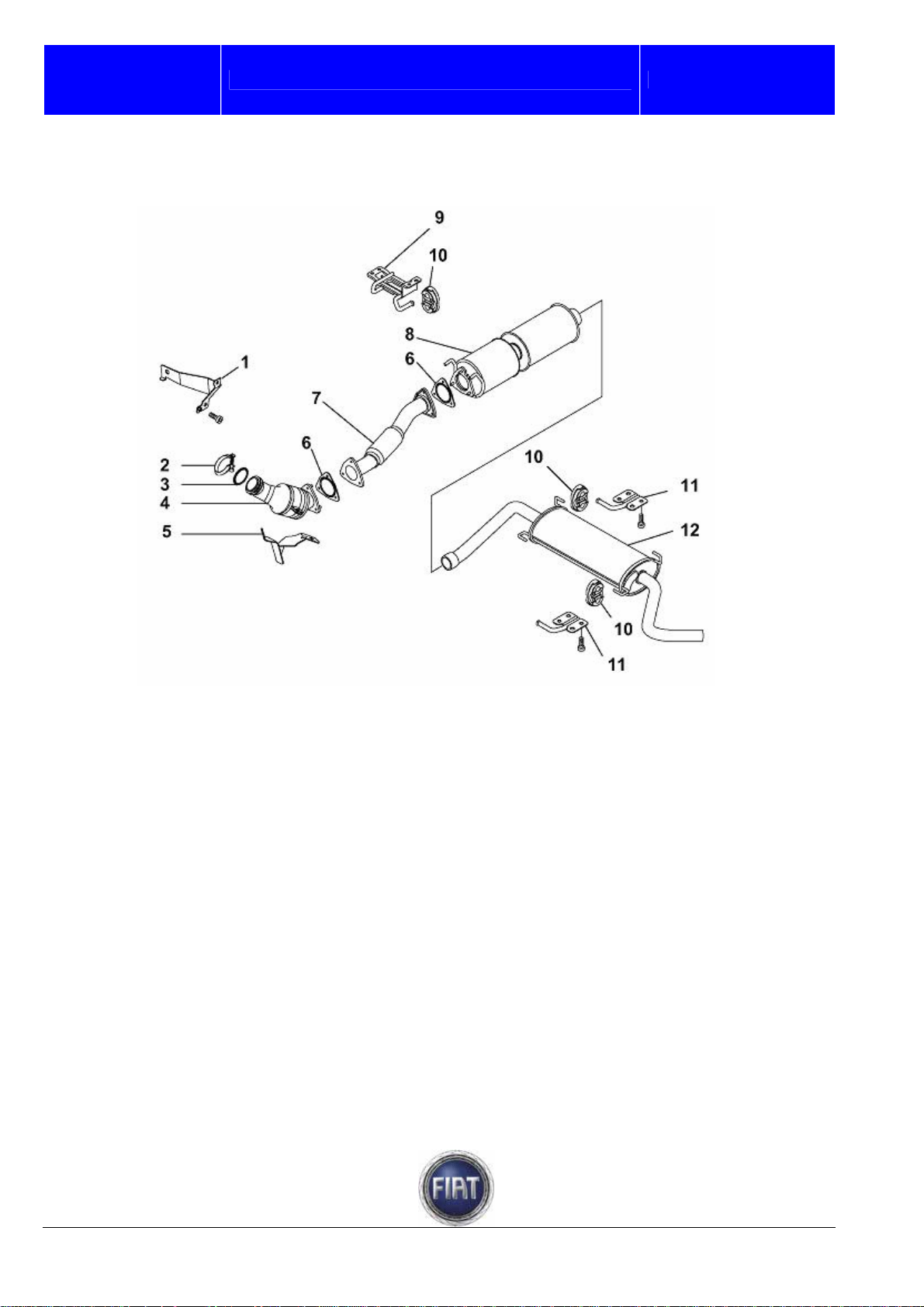
3.1.12 Exhaust system
The engine exhaust gases flow through the manifold to the three-way catalytic converter
1 – Pre-catalyst bracket
2 – Clamp
3 – Gasket
4 – Pre-catalyst
5 – Pre-catalyst bracket
6 – Gasket
FIAT DUCATO COURSE OUTLINE
7 – Exhaust pipe middle section
8 – Catalyst
9 – Catalyst bracket (on body)
10 – Flexible mounts
11 – Silencer bracket (on body)
12 – Silencer
Training Academy
© 2006 Fiat Auto S.p.A. - All rights reserved
30 / 182
Page 31

Fiat Auto S.p.A.
3.1.13 EGR system
GENERAL
This system recirculates part of the exhaust gases to the intake under certain particular operating
conditions.
This lowers peak temperature in the combustion chamber so as to reduce nitrogen oxide (NOx)
formation. The engine control unit recirculates a portion of the exhaust gases taken from the exhaust
manifold back to the engine intake.
To this end, the engine control unit processes the inputs from:
- atmospheric pressure sensor,
- water pressure sensor,
- engine rpm sensor,
- accelerator pedal potentiometer
and pilots both the vacuum control solenoid valve and the throttle valve via a PWM signal according to
the mapping stored in its memory.
Each time the engine control unit signals it to do so, the vacuum control solenoid valve opens a
connection between the servo brake vacuum circuit and the EGR circuit. This creates a certain amount of
vacuum in the EGR circuit according to the command signal. Vacuum operates the E.G.R. pneumatic
valve that retracts and lifts a shutter to open an exhaust gas passage to the intake.
This creates a connection between the exhaust and intake manifolds, so that part of the exhaust gases
flow into the intake manifold.
Exhaust gases are cooled while flowing through the heat exchanger and then conveyed into the throttle
valve chamber where they are mixed with the air from the intercooler and delivered to the intake manifold;
in the meantime, the engine control unit adjusts the amount of fuel injected into the cylinders depending
on the amount of exhaust gas recirculated.
When engine operating conditions are such that no gas recirculation is required (start-up, cold engine,
idle speed, load request, high altitude), the ECU sends no control signal to the vacuum control solenoid
valve. The solenoid valve closes the connection between the servo brake vacuum circuit and the E.G.R.
circuit and lets filtered air from the dedicated filter enter the E.G.R. circuit to restore atmospheric
pressure.
FIAT DUCATO COURSE OUTLINE
Training Academy
31 / 182
© 2006 Fiat Auto S.p.A. - All rights reserved
Page 32

Fiat auto S.p.A.
FIAT DUCATO COURSE OUTLINE
a – Servo brake vacuum circuit
b – E.G.R. controlled vacuum circuit
1 – Engine control unit
2 – Throttle valve assembly
3 – Vacuum take-up point
4 – Water temperature sensor
E.G.R. valve
The E.G.R. valve is mounted at the end of the heat exchanger.
The valve is cooled by the engine coolant coming out of the heat exchanger to ensure improved efficiency
and long life.
The amount of recirculated exhaust gas is determined by a poppet valve operated by the vacuum let in by
a calibrated connector; vacuum is taken from the pipe connecting vacuum pump to servo brake.
The vacuum let in by the solenoid valve overcomes the pressure exerted by the spring (1) and raises a
diaphragm (2); the shutter (3) connected to it rises and lets burnt exhaust gases flow back into the intake
manifold
.
Training Academy
5 – Engine rpm sensor
6 – E.G.R. pneumatic valve
7 – Air flow meter
8 – Intake air filter
9 – EGR vacuum control valve
10 – Vacuum-operated servo brake
1 – Vacuum duct,
© 2006 Fiat Auto S.p.A. - All rights reserved
2 – Spring
3 – Diaphragm.
4 – Shutter.
32 / 182
Page 33

Fiat Auto S.p.A.
FIAT DUCATO COURSE OUTLINE
Training Academy
E.G.R. solenoid valve
The E.G.R. solenoid valve operates the E.G.R. valve to determine the amount of exhaust gases to be
delivered to the intake duct.
The duty-cycle-controlled solenoid valve determines the amount of servo brake pump vacuum to be
connected to the E.G.R. valve so as to recirculate a certain amount of exhaust gas.
The figure below shows the layout of the EGR circuit.
1 – Servo brake vacuum pump
2 – Engine control unit
3 – E.G.R. solenoid valve
4 – Filter for connection to the atmosphere
5 – E.G.R. valve on engine
A – Exhaust gas from exhaust manifold
B – Exhaust gas recirculated to the intake
manifold
The figure below shows a detail diagram of the E.G.R. solenoid valve
1 – Connection to the atmosphere
2 – Electrical connector
3 – Connection to vacuum source
3a – White identification dot
4 – Connection to E.G.R. valve
4a – Yellow identification dot
33 / 182
© 2006 Fiat Auto S.p.A. - All rights reserved
Page 34

Fiat auto S.p.A.
FIAT DUCATO COURSE OUTLINE
Solenoid valve characteristic data
Pilot frequency: 140 ± 7Hz.
Minimum duty cycle value: 6%.
Maximum duty cycle value: 6%.
Maximum feed vacuum: 930 mbar.
Winding resistance: 5.5 ±5 Ohm at 20 ± 5°C
The following graph shows the solenoid valve characteristic curve
Training Academy
.
Heat exchanger
The heat exchanger installed between turbocharger and throttle valve assembly cools down exhaust gas
to reduce its volume.
Its body accommodates a set of corrugated pipes. The recirculated exhaust gas passing through the
pipes is cooled down by the engine coolant flowing inside the body.
© 2006 Fiat Auto S.p.A. - All rights reserved
34 / 182
Page 35

Fiat Auto S.p.A.
FIAT DUCATO COURSE OUTLINE
3.1.14 Crankcase oil vapour recovery system
General
A portion of combustion gases escapes past the end gaps of the piston rings into the sump; the oil fumes
in the sump become mixed with the exhaust gases.
From the chain compartment, this mixture is conveyed upwards, and oil is partly extracted by a device
located on top of the timing cover and conveyed into the air intake circuit. This device consists of a rotary
filter (3) splined to the shaft (1) of the high pressure/camshaft pump and a cover (2) that accommodates
two normally closed valves (4 and 5).
The diaphragm valve (4) controls the release of the partially filtered mixture to keep pressure inside the
chain compartment at ~ 10 ÷ 15 mbar. The umbrella valve (5) releases part of the remaining oil contained
in the mixture exiting the filter (3) into the chain compartment and oil condenses inside chamber (6).
Training Academy
A – Gas with an oil content greater than 10 g/h
B – Gas with an oil content ~ 0.2 g/h
C – Condensed oil returning to oil sump
35 / 182
© 2006 Fiat Auto S.p.A. - All rights reserved
Page 36

Fiat auto S.p.A.
OPERATION
As the mixture passes through the rotary filter (3), oil particles are extracted by centrifugal force, hit the
cover walls, condense and are conveyed back into the lubrication circuit.
FIAT DUCATO COURSE OUTLINE
Training Academy
The filtered mixture is made to pass through the shaft holes (1) and the diaphragm valve (4) lets it flow
into the air conveyor upstream of the turbocharger. The valve (4) is opened or closed by the combined
action of the pressure acting on the diaphragm (4) and the vacuum underneath it. Any oil left in the
mixture exiting the rotary filter (3) condenses inside chamber (6) and is released into the chain
compartment by the umbrella valve (5) when the engine is stopped and the vacuum keeping the valve
closed is removed
© 2006 Fiat Auto S.p.A. - All rights reserved
36 / 182
Page 37

Fiat Auto S.p.A.
3.1.15 Engine lubrication system
GENERAL
The forced lubrication system consists of the following components:
- gear oil pump incorporated in the same assembly as the vacuum pump;
- pressure regulator incorporated in the oil pump;
- five-element heat exchanger;
- duel-filtration oil filter with incorporated safety valve.
OPERATION
Engine oil is drawn from the sump through the suction rose by the oil pump, pressurised and delivered to
the heat exchanger for cooling.
Oil flows through the oil filter and is conveyed to all lubrication points through galleries or pipes.
After the lubrication cycle, the oil drips back into the sump. The safety valve incorporated in the oil filter
cuts off the filter from the circuit when it becomes clogged.
In addition, the lubricating oil feeds the hydraulic tensioners of the auxiliary drive shafts and camshafts as
well as the hydraulic tappets.
FIAT DUCATO COURSE OUTLINE
Training Academy
A – Pressure regulator closed
B – Pressure regulator open
C – Oil pressure switch
D – Pressurised oil
E – Dripping oil
E – Coolant
37 / 182
© 2006 Fiat Auto S.p.A. - All rights reserved
Page 38

Fiat auto S.p.A.
FIAT DUCATO COURSE OUTLINE
Oil pump/vacuum pump assembly
The oil pump/vacuum pump assembly is mounted on the crankcase on timing gear side.
The oil pump drive gear is driven by the crankshaft via a chain and transmits motion to the vacuum pump.
Note: this assembly cannot be serviced and must be replaced when faulty.
The figure below shows a cross-section view of the oil pump
1 – Oil pump
2 – Oil pressure regulator
3 – Vacuum pump
The oil pump is a gear pump; the vacuum
pump is a radial vane pump.
1 – Inlet duct for crankcase oil
2 – Oil intake duct
3 – Oil pressure regulator
4 – Oil delivery duct
5 – Vacuum pump air intake duct
6 – Vacuum pump oil intake duct
Oil pressure regulator
The oil pressure regulator is housed inside
the pump. The figure below shows its
components.
1 – Circlip
2 – Valve
3 – Spring
4 – Valve body.
Training Academy
© 2006 Fiat Auto S.p.A. - All rights reserved
38 / 182
Page 39

Fiat Auto S.p.A.
Oil pressure regulator valve closed
Oil pressure regulator valve open
Oil filter
FIAT DUCATO COURSE OUTLINE
When oil pressure in duct C drops below
4.4 bar, the valve (1) shuts holes D and E
and the pressurised oil is delivered to the
crankcase.
1 – Valve
2 – Spring
A – Sump oil intake duct
B – Oil delivery duct to crankcase
C – Oil return duct from crankcase
D – Oil drain hole
E – Oil drain hole
When pressure in duct C is 4.4 bar or
higher, it helps the valve (1)
overcome the spring (2); the valve lowers
and opens the drain holes D-E that connect
delivery duct A and intake duct B, so that
pressure drops.
As soon as pressure drops below 4.4 bar,
the spring (2) pushes the valve (1) back into
the closed position.
The oil filter is of the simple filtration type
with incorporated by-pass valve and opens
at a differential pressure of 2.5 ± 0.2 bar.
Training Academy
39 / 182
© 2006 Fiat Auto S.p.A. - All rights reserved
Page 40

Fiat auto S.p.A.
Heat exchanger
The figure below shows the heat exchanger.
The amount of oil in the circuit and oil pressure are continually monitored by:
- oil pressure sensor,
- oil level sensor,
- engine oil level control unit.
Engine oil pressure sensor
The engine oil pressure sensor is located near the oil filter on the water-oil heat exchanger.
FIAT DUCATO COURSE OUTLINE
1 – Five-element heat exchanger
2 – Gasket
3 – Case
4 – Fitting
5 – Screw
6 – Oil filter mount
7 – Oil pressure switch
8 – Screw
9 – Heat exchanger case
10 – Gasket
Training Academy
1 – Engine oil pressure sensor
© 2006 Fiat Auto S.p.A. - All rights reserved
40 / 182
Page 41

Fiat Auto S.p.A.
FIAT DUCATO COURSE OUTLINE
The figure below shows the engine oil pressure sensor.
A – Detail of connector
1 – Connector
2 – Engine oil pressure sensor body
3 – Gasket
Engine oil level sensor
The engine oil level sensor is located near the alternator, on the crankcase exhaust side.
1 – Engine oil level sensor
The engine oil level sensor is a hot-wire
sensor.
The figure below shows the engine oil level sensor.
1 – Connector
2 – Engine oil level sensor body
3 – Gasket
Training Academy
41 / 182
© 2006 Fiat Auto S.p.A. - All rights reserved
Page 42

Fiat auto S.p.A.
Engine oil level measurement
The system consists of an electronic control unit located near the engine control unit in the engine
compartment and a hot-wire sensor.
FIAT DUCATO COURSE OUTLINE
A – Engine oil level control unit
B – Detail of connector
1 – +12 Volt
2 – Output signal level
3 – Oil level sensor +
4 – Ground
5 – Ground signal
6 – Oil level sensor ground
Training Academy
Engine oil level is checked when the ignition key is turned to On to start the engine.
The system uses the heat dissipating properties of oil.
The current flowing through the hot wire causes its temperature and resistance to rise, while voltage
drops.
When the hot wire is submerged in oil, the oil will take up part of the heat; as a result, temperature,
resistance and voltage drop will be lower.
When the key is turned to On, the control unit feeds 210.5mA to the hot wire of the sensor. After a time
delay to allow for power supply to stabilise (t0 ÷ t1 = 150 mSec), the control unit takes a first voltage
reading (t1 ÷ t2 = 10 mSec ).
After another time delay (t0 ÷ t1 = 865 mSec), the control unit takes a second voltage reading and
compares it to the first reading.
At this point, one of the following may occur:
1) if the difference between the two readings is less than 125mV, it means that oil level is correct;
2) a difference greater than 445mV indicates minimum oil level;
3) if the second reading is greater than 3.5mV, it means that the sensor is interrupted;
4) if voltage is less than 1mV, it means that the sensor is shorted.
The oil control unit converts the reading into a PWM signal and sends it to the engine control unit. The
engine control unit sends the corresponding parameter over the C-CAN network to trigger the necessary
indications on the instrument panel.
PWM frequency : 125 ± 10Hz
Tolerance at ambient temperature PWM ± 3.5%
Oil level PWM signal represented by duty cycle TA
/ TP.
At the minimum level the PWM will be at 30%
(440mV) whereas at the max level it will be 90%
(125mV).
Between 10% and 15%, data acquisition is in
progress.
Between 3% and 7%, an error has occurred.
© 2006 Fiat Auto S.p.A. - All rights reserved
42 / 182
Page 43

Fiat Auto S.p.A.
3.1.16 Engine cooling circuit
The engine forced cooling system is a closed circuit and consists of the following components:
- expansion tank with an inlet and outlet valve incorporated in the plug to regulate circuit pressure;
- engine cooling module to dissipate the heat removed from the engine by the coolant;
- heat exchanger that cools lubricating oil;
- heat exchanger for exhaust gas (EGR) cooling;
- centrifugal water pump incorporated in crankcase;
- thermostat controlling coolant circulation
Diagram showing engine cooling system operation
FIAT DUCATO COURSE OUTLINE
Training Academy
1. Coolant pump
2. Coolant tank
3. Radiator
4. Thermostat
5. Oil/coolant heat exchanger
43 / 182
6. Exhaust gas/coolant heat
exchanger
7. Bleed screw
8. In-cab heater
© 2006 Fiat Auto S.p.A. - All rights reserved
Page 44

Fiat auto S.p.A.
Engine coolant pump
The engine coolant pump is driven by the crankshaft via a poli-V belt; the pump delivers coolant to the
crankcase and - with greater pressure head - to the cylinder head.
The engine coolant pump is located on the crankcase on timing gear side.
When coolant temperature reaches or exceeds operating temperature, the thermostat trips and conveys
coolant to radiator and cooling fan.
Pressure in the circuit varies with temperature and is controlled by the inlet and outlet valves incorporated
in the expansion tank filler plug.
Supplemental engine coolant tank
The tank feeds coolant to the circuit and takes up excess coolant when it expands from heat as engine
temperature rises.
A calibrated valve in the sealed plug
- lets air exit the circuit; this is the air drawn from the pipe coming from the coolant outlet fitting on the
head; or
- lets air in when the engine has cooled down and vacuum is created in the circuit.
FIAT DUCATO COURSE OUTLINE
1 – Engine coolant pump
2 – Seal
3 – Pipe connecting pump to expansion
tank
1 – Expansion tank
2 – Engine coolant level sensor connector
3 – Fitting for coolant delivery to engine
cooling circuit
4 – Engine breather fitting
5 – Radiator breather fitting
6 – Expansion tank plug
Training Academy
© 2006 Fiat Auto S.p.A. - All rights reserved
44 / 182
Page 45

Fiat Auto S.p.A.
FIAT DUCATO COURSE OUTLINE
Expansion tank plug
The expansion tank plug maintains pressure in the cooling circuit within the specified range.
The plug accommodates two valves:
- one is set at 0.02÷0.07 kg/cm² and lets air at atmospheric pressure into the circuit to prevent vacuum
(inlet valve);
- the other valve is set at 1.4±0,1 kg/ cm² and releases exceeding pressure (outlet valve).
The outlet valve serves two purposes:
- it maintains a slight pressure in the circuit so as to increase coolant boiling point;
- it releases excess pressure to the atmosphere when coolant temperature rises.
The inlet valve lets air into the circuit when coolant cools down and shrinks in volume, creating vacuum in
the circuit.
Thermostat
The thermostat is housed inside the outlet manifold for the engine coolant exiting the head on the intake
side, and its purpose is to maintain ideal engine temperature:
Training Academy
1
– Threaded cover
2 – Cover
3 – Outlet valve spring
4 – Inlet valve
5 – Outlet valve
6 – Inlet valve spring
7 – Outlet valve
8 – Lower cover
9 – Sealing O-ring
The by-pass thermostat requires no adjustment.
If you suspect a malfunction, replace it.
The water temperature sensor is mounted on thermostat body.
Valve travel at 79°C ± 2°C = 0.1 mm
Valve travel at 94°C ± °C = 7 mm
Valve travels 7 mm in less than 60”.
A – Thermostatic valve closed
B – Thermostatic valve open
45 / 182
© 2006 Fiat Auto S.p.A. - All rights reserved
Page 46

Fiat auto S.p.A.
FIAT DUCATO COURSE OUTLINE
3.2 ELECTRONIC ENGINE MANAGEMENT
FEATURES
The EDC16C39 Common Rail system is a high-pressure electronic injection system for fast directinjection diesel engines.
Its main features comprise:
- high injection pressures (1600 bar);
- pressure control range from 150 bar up to maximum operating pressure (1600 bar), regardless of
engine speed and loading;
- operation at high engine rpm (up to 6000 rpm under full loading);
- high pressure pump with three pumping elements;
- accurate injection (advance and duration) control;
- less consumption;
- less emissions.
The main features of the system are outlined below:
- fuel temperature control;
- engine coolant temperature control;
- injected fuel control;
- idle speed control;
- fuel cut-off during deceleration;
- cylinder balance control at idle speed;
- surge control;
- exhaust smoke control under acceleration;
- exhaust recirculation control (E.G.R.)
- torque limitation control;
- rpm limitation control;
- glow plug control;
- air conditioner control (where fitted);
- electric fuel pump control;
- cylinder position control;
- main and pilot injection advance control;
- closed-loop injection pressure control;
- electrical balance control;
- turbocharging pressure control;
- self-diagnosis;
- connection to Fiat CODE (Immobilizer) control unit.
Training Academy
© 2006 Fiat Auto S.p.A. - All rights reserved
46 / 182
Page 47

Fiat Auto S.p.A.
FIAT DUCATO COURSE OUTLINE
Training Academy
1 – Auxiliary fuel pump
2 – Fuel filter
3 – Fuel return manifold
4 – CP3.2 pressure pump
5 – Pressure regulator on pump
6 – Supercharging sensor
7 – Injection control unit
8 – Pressure sensor
9 – Rail
10 – Throttle body
11 – E.G.R. solenoid valve
12 – Oil level sensor
13 – E.G.R. actuator
14 – Glow plug
15 – Glow plug control unit
16 – Air flow meter
17 – Rpm sensor
18 – Timing sensor
19 – Oil minimum pressure switch
20 – Lambda sensor on pre-catalyst
21 – Main catalyst
22 – Engine wiring harness
23 – Pedal unit
24 – Vehicle wiring harness
25 – Water temperature sensor
47 / 182
© 2006 Fiat Auto S.p.A. - All rights reserved
Page 48

Fiat auto S.p.A.
3.2.1 EDC 16 C 39 engine control
FEATURES
In this Common Rail fuel injection system equipped with CP3.2 pump, the flow regulator located at the
high pressure pump inlet controls the fuel flow required by the low pressure circuit. The high pump
pressure then feeds the Rail as appropriate.
This way, only the necessary amount of fuel is pressurised, there is less need to heat fuel in the system
and overall energy efficiency is improved
The CP3.2 pump maintains fuel at high pressure regardless of the current stroke of the cylinder that is
expecting the fuel and stores the fuel in a common duct for all electro-injectors (Rail).
As a result, fuel at the injection pressure determined by the ECU is constantly available at injector inlets.
When the ECU energises the solenoid valve of an injector, fuel is drawn from the rail and injected into the
corresponding cylinder.
The hydraulic system is comprised of a low pressure and high pressure circuit. The high pressure circuit
consists of the following pipes:
- pipe connecting high pressure pump outlet to Rail;
- Common Rail;
- feed pipes from Rail to injectors.
The low pressure circuit consists of the following pipes:
- suction pipe from tank to prefilter
- pipes feeding the mechanical supply pump and prefilter;
- pipes feeding the high pressure pump through the fuel filter;
- return pipe from high pressure pump;
- return pipe from electro-injectors;
- return pipe to tank.
Because of the high pressures in this hydraulic circuit, the following safety precautions must be strictly
observed:
- make sure to tighten the high pressure pipe fittings to the correct torque;
- do not disconnect high pressure pipes while the engine is running (DO NOT attempt to bleed the circuit,
this would be useless and dangerous!)
A low pressure circuit in good running order is critical to proper operation of the system, so do not make
changes to the circuit and repair any leaks without delay.
INJECTED FUEL CONTROL
The control unit controls fuel pressure regulator and electro-injectors based on the inputs from accelerator
pedal potentiometer, air flow meter or air pressure sensor in intake manifold and engine rpm sensor.
When the engine is started, injection timing and firing order are determined using the inputs from the
engine rpm sensor and the timing sensor (synchronisation); afterwards, injection timing is dependant on
the engine rpm sensor inputs only and the standard firing order of the 3000 JTD engine (1 – 3 – 4 – 2) is
resumed.
The control unit inhibits the injection when:
- fuel pressure exceeds 1700 bar;
- fuel pressure drops below 100 bar;
- engine rpm exceeds 5000 rpm.
FIAT DUCATO COURSE OUTLINE
Training Academy
© 2006 Fiat Auto S.p.A. - All rights reserved
48 / 182
Page 49

Fiat Auto S.p.A.
FIAT DUCATO COURSE OUTLINE
Training Academy
INJECTION ADVANCE CONTROL
The electronic control unit basically relies on two factors to calculate injection advance: the amount of fuel
to be injected and engine rpm.
Injection advance is adjusted according to engine coolant temperature so as to compensate for the
increasing injection delay during warm-up, while the combustion chambers are still cold.
INJECTION PRESSURE CONTROL
This is a critical feature, as injection pressure affects the following parameters:
- amount of fuel fed into the cylinders (injection duration being equal);
- fuel atomisation;
- injection depth;
- time delay after command signal before fuel is actually injected;
- duration of fuel injection into combustion chamber.
These parameters significantly affect engine operation and performance in terms of power output,
exhaust emissions, noise and driveability.
The engine control unit uses engine rpm and load inputs to control the pressure regulator at the high
pressure pump inlet so as to achieve and maintain optimal line pressure.
When the engine is cold, injection pressure is adjusted based on engine coolant temperature to meet
varying engine demand as operating temperature changes.
Fuel pressure is adjusted to instantaneous engine operating conditions (rpm, load, etc.).
The lower the pressure, the longer the injection times (and vice versa), also depending on load
requirements.
Up to 2800 rpm, a pre-injection feature reduces the noise typically associated with direct injection
systems.
Pre-injection advance angles, intervals between pre-injection and main injection and main injection
advance angles vary according to the instantaneous operating conditions of the engine.
ELECTRIC FUEL PRE-FEED PUMP CONTROL
The auxiliary fuel pump submerged in the tank is powered by the engine control unit through a contactor
when the ignition key is set to RUN.
Power supply to the electric pump is removed when:
- the engine has not started after the ignition key has been in the RUN position for 10 seconds;
- the inertia switch has tripped.
FUEL CUT-OFF DURING DECELERATION
Fuel cut-off occurs when the engine control unit receives an input from the potentiometer indicating that
the accelerator has been released.
In this condition, the control unit cuts off power supply to electro-injectors and restores it before idle rpm is
reached; the ECU also controls the fuel pressure regulator accordingly.
49 / 182
© 2006 Fiat Auto S.p.A. - All rights reserved
Page 50

Fiat auto S.p.A.
FIAT DUCATO COURSE OUTLINE
Training Academy
IDLE SPEED CONTROL
The control unit controls fuel pressure regulator and electro-injector timing based on the inputs from the
engine rpm and coolant sensors so as to keep idle rpm stable. Under certain conditions, the ECU will also
use battery voltage to control idle speed.
MAXIMUM RPM LIMITATION CONTROL
The engine control unit achieves rpm limitation in two ways:
- it lowers line pressure to reduce the amount of fuel injected as the engine is approaching the maximum
rpm limit (4500 rpm);
- it shuts down the electro-injectors in the event the engine exceeds 5000 rpm.
MAXIMUM TORQUE LIMITATION CONTROL
The injection control unit uses rpm to calculate maximum torque parameters and maximum smoke rate
allowed based on the mapping stored in its memory. The control unit adjusts these parameters based on
engine coolant temperature and vehicle speed, and uses the resulting corrected parameters to meter out
the correct amount of fuel through the pressure regulators and the electro-injectors.
FUEL TEMPERATURE CONTROL
The injection control unit continually monitors fuel temperature through the sensor in the fuel filter.
When fuel reaches a predetermined temperature (80°C), the engine control unit begins to gradually
decrease maximum power and keeps cutting power up to 90°C, until achieving a minimum value of 60%
of rated power.
ENGINE COOLANT TEMPERATURE CONTROL
The injection control unit continually monitors engine coolant temperature through the sensor on the
thermostat.
If engine coolant temperature exceeds certain predetermined values, the control unit will:
- signal the fuel pressure regulator and the electro-injectors to reduce the amount of fuel injected (power
reduction starting from 106°C).
- actuate the engine cooling fan (switch-on/off temperatures: 95 / 91°C for first speed, 99 / 95°C for
second speed).
When the ignition key is turned to STOP (and temperature is higher than the cooling system switch-on
threshold), the fan will keep running for up to 20 sec., so that temperature drops below the switch-on
threshold.
When the ignition key is turned to RUN (and coolant temperature is higher than the cooling system
switch-on threshold), the fans will not switch on until engine speed rises above 770 rpm (rpm with a warm
engine is 800 rpm).
© 2006 Fiat Auto S.p.A. - All rights reserved
50 / 182
Page 51

Fiat Auto S.p.A.
FIAT DUCATO COURSE OUTLINE
Training Academy
EXHAUST SMOKE RATE CONTROL
The injection control unit also provides smoke limitation, for event smoke emissions are produced under
sharp acceleration
To meet this requirement, the control unit processes the signals sent by accelerator pedal potentiometer,
engine rpm sensor and intake air sensor (air flow meter or pressure/temperature sensor); the injection
control unit controls the fuel pressure regulator and the electro-injectors so that the right amount of fuel to
reduce exhaust smoke is injected into the combustion chamber .
EXHAUST RECIRCULATION CONTROL (E.G.R.)
To ensure compliance with EURO 4 emissions standard, the control unit reduces the amount of fresh air
taken in according to engine load and accelerator pedal potentiometer inputs, and signals the pneumatic
EGR valve to open so as to draw a portion of the exhaust gas.
AIR CONDITIONER CONTROL
The engine control unit controls the air conditioner compressor clutch so as to preserve engine
performance when the air conditioner is on.
When the air conditioner is switched on, the engine control unit provides more fuel at idle speed to meet
the increased demand from the engine and shuts down the air conditioner in the event of:
- exceeding engine coolant temperature (AC is shut down at 105°C and re-enabled at 100°C).
ENGINE IMMOBILIZER
The system offers an engine immobilizer feature. This is achieved thanks to a Fiat CODE control unit that
communicates with the engine control unit and an electronic key that incorporates a code transponder.
Each time the key is turned to STOP, the Fiat CODE system shuts down the engine control unit
completely.
When the key is turned to RUN, the following occurs in the order:
- the engine control unit (which has the secret code stored in its memory) asks the Fiat CODE control unit
to transmit the secret code required to cancel the inhibit condition;
- the Fiat CODE control unit will only send the secret code after receiving the identification code from the
key transponder;
- when the secret code is recognised, the engine control unit inhibit is disabled and the unit is restored to
normal operation.
SELF-DIAGNOSIS
The injection system can be fully diagnosed by connecting the EXAMINER equipment to the diagnostic
connector located in the engine compartment.
The system includes a self-diagnosis feature to recognise, store and warn of possible malfunctions.
In the event a sensor or actuator is found to be malfunctioning, preset signal recovery strategies ensure
acceptable engine operation. This way, the vehicle can be driven to nearest service centre for the
necessary repairs.
51 / 182
© 2006 Fiat Auto S.p.A. - All rights reserved
Page 52

Fiat auto S.p.A.
FIAT DUCATO COURSE OUTLINE
FIXED GEOMETRY TURBINE CONTROL (VGT)
The control unit processes the supercharging sensor inputs at varying engine rpm and determines the
amount of fuel to be injected:
- the ECU adjusts injection duration;
- it adjusts the amount of exhaust gas flowing through the turbocharger so as to ensure optimal
performance under all operating conditions.
LAMBDA SENSOR CONTROL
The control unit uses the inputs from the Lambda sensor to prepare “correction maps” for the main injection
and compensate for injection component decay (EGR, injectors, pressure rail, air flow meter, Lambda
sensor)
SOLENOID VALVE CONTROL
The control unit switches on the cooling fans at the first or second speed depending on engine coolant
temperature and coolant pressure in the air conditioning system.
CRUISE CONTROL (WHERE FITTED)
The control unit directly adjusts the amount of fuel injected depending on the position of the cruise control
lever so as to control and maintain the vehicle speed stored in the memory.
It also controls a status light on the instrument panel to indicate whether the system is on or off.
The cruise control system is temporarily disabled:
- when the brake is operated,
- when the clutch is operated;
- pressing the "resume" button brings the vehicle back to the stored speed.
The cruise control is not disabled when the accelerator pedal is depressed (for instance, when overtaking)
and automatically brings the vehicle back to stored speed as soon as the accelerator is released.
For safety reasons, the ASR (antispin) feature overrides the cruise control.
3.2.2 Engine Control unit pinout
Training Academy
© 2006 Fiat Auto S.p.A. - All rights reserved
52 / 182
Page 53

Fiat Auto S.p.A.
FIAT DUCATO COURSE OUTLINE
M010A connector
1 – Key-on power source from main
contactor
2 – Control unit ground 1
3 – NC
4 – Control unit ground 2
5 – Key-on power source from main
contactor
6 – Control unit ground 3
7 – NC
8 – Accelerator pedal potentiometer 2
ground
9 – Accelerator pedal potentiometer 1
signal
10 – Fuel temperature signal (ground)
11 – Fuel temperature signal (signal)
12 – Air conditioner linear pressure sensor
(ground)
13 – Air conditioner linear pressure sensor
(signal)
14 – NC
15 – NC
16 – NC
17 – Brake pedal switch (signal)
18 – NC
19 – NC
20 – Fuel pump contactor power supply
(positive)
21 – NC
22 – Air conditioner linear pressure sensor
(power supply)
23 – NC
24 – NC
25 – K line for diagnosis
26 – NC
27 – NC
28 – Direct power supply from switch +15
29 – Compressor cut-in contactor control
30 – Accelerator pedal potentiometer 1
ground
31 – Accelerator pedal potentiometer 2
signal
32 – DPF exhaust gas temperature signal
(where fitted)
33 – DPF exhaust gas temperature ground
(where fitted)
34 – Exhaust gas temperature sensor 1
signal (where fitted)
35 – Exhaust gas temperature sensor 1
ground (where fitted)
36 – Particulate filter differential sensor
signal (where fitted)
Training Academy
37 – Particulate filter differential sensor
negative power supply (where fitted)
38 – Resume from cruise control command
39 – NC
40 – NC
41 – NC
42 – NC
43 – NC
44 – Particulate filter differential sensor
power supply (where fitted)
45 – Accelerator pedal potentiometer 1
power supply
46 – Accelerator pedal potentiometer 2
power supply
47 – NC
48 – NC
49 – NC
50 – NC
51 – Lambda sensor heating (negative)
52 – Glow plug preheating time/fault
detection feedback input
53 – NC
54 – Compressor cut-in request from
pushbutton positive signal
55 – NC
56 – Cruise control for “set / acc.”
57 – NC
58 – NC
59 – NC
60 – NC
61 – NC
62 – NC
63 – NC
64 – Lambda sensor Nerst cell reference
voltage signal
65 – Lambda sensor pumping current
66 – NC
67 – NC
68 – (Provision for) Diesel filter heater
contactor command
69 – Engine cooling fan speed contactor 2
cut-in command
70 – NC
71 – Malfunction indicator light (EOBD/MIL)
72 – Direct power supply from battery
73 – NC
74 – Water in fuel sensor (signal)
75 – NC
76 – NC
77 – Cruise control on/off control lever
positive
78 – Cruise control “set/dec.” command
positive
79 – Clutch pedal pressed positive signal
(NC switch)
53 / 182
© 2006 Fiat Auto S.p.A. - All rights reserved
Page 54

Fiat auto S.p.A.
FIAT DUCATO COURSE OUTLINE
80 – Clutch pedal pressed redundant signal
(positive), normally closed.
81 – NC
82 – NC
83 – Can line from NBC – (Can low)
84 – Can line from NBC – (Can High)
85 – NC
86 – Ground for Lambda sensor signal
87 – Lambda sensor reference current
88 – NC
89 – NC
90 – Engine cooling fan speed contactor 1
cut-in command
91 – NC
92 – NC
93 – Glow plug preheating contactor
94 – Engine cooling fan speed contactor 3
cut-in command
M010B Connector
1 – Injector no. 3, supply
2 – Injector no. 2, supply
3 – NC
4 – NC
5 – NC
6 – NC
7 – NC
8 – Fuel pressure sensor (ground)
9 – NC
10 – NC
11 – Timing sensor (power supply)
12 – Rpm sensor (negative input)
13 – Absolute pressure sensor (power
supply)
14 – NC
15 – NC
16 – Injector no. 1, supply
17 – Injector no. 4, supply
18 – NC
19 – Fuel flow regulator (power supply)
20 – Timing sensor (negative)
21 – NC
22 – Oil level sensor (ground)
Training Academy
23 – Absolute pressure sensor (negative)
24 – NC
25 – NC
26 – NC
27 – Rpm sensor (positive input)
28 – Rail pressure sensor (positive)
29 – NC
30 – NC
31 – Injector 2 (negative command)
32 – NC
33 – Injector 4 (negative command)
34 – NC
35 – NC
36 – NC
37 – Air temperature sensor (signal) inside
air flow meter
38 – NC
39 – NC
40 – Absolute pressure sensor (signal)
41 – Water temperature sensor (ground)
42 – Air mass quantity in flow meter signal
43 – Fuel pressure sensor on rail (signal)
44 – Air flow meter (ground)
45 – NC
46 – Injector 3 (negative command)
47 – Injector 1 (negative command)
48 – NC
49 – Flow regulator control (negative)
50 – Timing sensor (signal)
51 – NC
52 – Oil level sensor (signal)
53 – Air temperature signal of absolute
pressure sensor
54 – NC
55 – NC
56 – Signal oil pressure sensor (normally
closed)
57 – NC
58 – Water temperature sensor (signal)
59 – Powered throttle actuator command
60 – EGR negative command
© 2006 Fiat Auto S.p.A. - All rights reserved
54 / 182
Page 55

Fiat Auto S.p.A.
FIAT DUCATO COURSE OUTLINE
3.2.3 Engine management wiring diagram
Training Academy
55 / 182
© 2006 Fiat Auto S.p.A. - All rights reserved
Page 56

Fiat auto S.p.A.
FIAT DUCATO COURSE OUTLINE
Training Academy
© 2006 Fiat Auto S.p.A. - All rights reserved
56 / 182
Page 57

Fiat Auto S.p.A.
FIAT DUCATO COURSE OUTLINE
Training Academy
57 / 182
© 2006 Fiat Auto S.p.A. - All rights reserved
Page 58

Fiat auto S.p.A.
Key to engine management wiring diagram components
A040. Preheating glow plugs
B001. Engine compartment connector box
B002. Connector box under dashboard
B099. Pmaxi-fuse box on battery
C010. Front left ground
C022. Central dashboard ground
C100. Cab ground
D001. Dashboard/front junction
D004. Engine/front junction
E050. Instrument panel
H001. Ignition switch
I030. Brake pedal switch
I031. Clutch pedal switch
I050. Inertia switch
K030. Engine oil pressure sensor
K031. Water in diesel filter sensor
K032. Engine oil level sensor
K036. Engine water temperature sensor
K040. Lambda sensor
K041. Air flow meter
K044. Intake air pressure and temperature sensor
K046. Rpm sensor
K047. Timing sensor
K055. Accelerator pedal potentiometer
K081. Fuel temperature sensor
K083. Fuel pressure sensor
L030. EGR solenoid valve
L062. Throttle body
M001. Body computer
M010. Engine control unit
M015. Glow plug preheating control unit
M186. Engine oil level control unit
N040. Electric fuel pump and fuel level meter
N070. Electro-injectors
N193. Fuel flow regulator
O007. Oil vapour heating resistor
FIAT DUCATO COURSE OUTLINE
Training Academy
© 2006 Fiat Auto S.p.A. - All rights reserved
58 / 182
Page 59

Fiat Auto S.p.A.
FIAT DUCATO COURSE OUTLINE
3.2.4 Injection/ignition system components
ENGINE CONTROL UNIT
It is fitted in the engine compartment on the right-hand side panel.The control unit is of the "flash
e.p.r.o.m." type, i.e. it can be reprogrammed from outside without removing the hardware.
The injection control unit incorporates the absolute pressure sensor.
The figure below shows the control unit.
RPM SENSOR
Features
TIMING SENSOR
Features
Training Academy
The rpm sensor is fitted on the crankcase
with its sensing surface facing the phonic
wheel on the engine flywheel. It is an
inductive sensor that changes its output as
it senses the changes in the magnetic field
caused by the phonic wheel teeth (60 - 2
teeth) passing across it.
The injection control unit uses the rpm
sensor signal to:
- determine the rotation speed;
- determine the angular position of the
crankshaft.
The timing sensor is a Hall sensor fitted on
engine oil filler cover on the upper cylinder
head section.
It determines engine timing by sensing
the position of intake camshaft drive gear.
The injection control unit uses the signal of
the timing sensor to determine T.D.C. at the
end of the compression stroke.
1 –Timing sensor
59 / 182
© 2006 Fiat Auto S.p.A. - All rights reserved
Page 60

Fiat auto S.p.A.
FIAT DUCATO COURSE OUTLINE
Training Academy
INTAKE AIR TEMPERATURE AND OVERPRESSURE SENSOR
Features
The intake air overpressure and temperature sensor is an integrated component used to measure the
pressure and temperature of the air inside the intake manifold.
The sensor is fitted on the intake manifold and its output is used by the engine control unit:
- to adjust turbocharger pressure
- to protect the engine from overheating
- to diagnose air flow meter operation
Sensor pinout:
1 – Ground
2 – Air temperature signal
Sensor output voltage changes with absolute pressure according to the following law:
Ua=(c1*pabs+c0)*Us
where:
- Ua = signal output voltage in V
- Us = power supply voltage in V
- pabs = absolute pressure in kPa
- c0 = 5.4/280
- c1 = 0.85/280 kPa-1
3 – 5 V power supply (from engine control
unit)
4 – Turbocharging pressure output signal
© 2006 Fiat Auto S.p.A. - All rights reserved
60 / 182
Page 61

Fiat Auto S.p.A.
FIAT DUCATO COURSE OUTLINE
The graph below shows output signal tolerance in relation to pressure
Training Academy
.
61 / 182
© 2006 Fiat Auto S.p.A. - All rights reserved
Page 62

Fiat auto S.p.A.
FIAT DUCATO COURSE OUTLINE
The following table lists temperature sensor resistance values in relation to air
temperature
Temperature
(°C)
Minimum Rated Maximum
-40 45301 48153 51006
-35 33703 35763 37823
-30 25350 26854 28359
-25 19265 20376 21487
-20 14785 15614 16443
-15 11453 12078 12702
-10 8951 9426 9901
-5 7055 7419 7783
0 5605 5887 6168
5 4487 4707 4926
10 3618.7 3791.1 3693.5
15 2938.5 3074.9 3211.3
20 2401.9 2510.6 2619.3
25 1975.8 2062.9 2150.1
30 1644.7 1715.4 1786.2
35 1374.2 1431.8 1489.5
40 1152.4 1199.6 1246.7
45 969.9 1008.6 1047.4
50 819.1 851.1 883.0
55 694.2 720.7 747.1
60 590.3 612.3 634.2
65 503.6 521.9 540.2
70 431.0 446.3 461.6
75 370.1 382.89 395.7
80 318.68 329.48 340.27
85 275.25 284.37 293.48
90 238.43 246.15 253.86
95 207.12 213.67 220.23
100 180.42 186.00 191.58
105 157.37 162.35 167.32
110 137.63 142.08 146.52
115 120.68 124.66 128.63
120 106.09 109.65 113.21
125 93.48 96.68 99.88
130 82.58 85.45 88.32
Resistance in Ohm
Training Academy
© 2006 Fiat Auto S.p.A. - All rights reserved
62 / 182
Page 63

Fiat Auto S.p.A.
FIAT DUCATO COURSE OUTLINE
Training Academy
ENGINE COOLANT TEMPERATURE SENSOR
The engine coolant temperature sensor is
mounted on a thermostatic plate and
detects coolant temperature by means of a
double NTC (negative temperature
coefficient) thermistor.
One NTC thermistor sends a signal to the injection control unit, while the other sends a signal to
temperature indicator and light on the instrument panel.
The sensor uses semiconductor technology; as sensor temperature increases with coolant temperature,
sensor resistance drops.
The change in resistance is not linear; temperature increase being equal, resistance will drop faster in the
low temperature range than at higher temperatures.
AIR FLOW METER WITH INCORPORATED AIR TEMPERATURE SENSOR
Features
The hot-film air flow meter is located on the air intake sleeve.
It incorporates the intake air temperature sensor.
Air flow meter pinout:
1 – Power supply
2 – Ground
3 – Air temperature sensor signal
4 – Air mass quantity signal
63 / 182
© 2006 Fiat Auto S.p.A. - All rights reserved
Page 64

Fiat auto S.p.A.
FIAT DUCATO COURSE OUTLINE
Training Academy
ACCELERATOR PEDAL POTENTIOMETER
Features
The sensor casing is secured to the accelerator pedal and accommodates two (main and safety)
potentiometers connected by an axial shaft.
The shaft is fitted with two springs: a coil spring provides the correct resistance when pressure is applied
to the pedal, the second is the return spring for when the pedal is released.
Sensor output voltage changes with accelerator pedal position and is sent to the injection control unit.
The accelerator pedal position signal is processed together with the rpm input to calculate injection times
and pressure.
MOTOR-DRIVEN THROTTLE BODY
Double potentiometer = factor 2
Power supply voltage (U1, U2) = 5 V ± 0.3 V
Series and contact resistance (Rs + Rc) = 1 kOhm ±0.4 kOhm
Maximum load on sliding contact = 0.5 micro Ampere
Potentiometer resistance Rn1 = 1.2 kOhm ±0.5 kOhm
Potentiometer resistance Rn2 + Rv2 = 1.7 kOhm ±0.8 kOhm
Linearity = ±0.02 u/U
P1/P2 synchronisation = absolute value(u1/(U1/2)-u2/U2) ≤ 0.014 u
1 – Accelerator pedal potentiometer 2
power supply
2 – Accelerator pedal potentiometer 1
power supply
3 – Accelerator pedal potentiometer 1
ground
4 – Accelerator pedal potentiometer 1
signal
5 – Accelerator pedal potentiometer 2
ground
6 – Accelerator pedal potentiometer 2
signal
The (normally open) throttle valve assembly fitted on the intake manifold controls the flow rate of
intercooler air to be mixed with the exhaust gases recirculated by the E.G.R. valve, according to a
programmed percentage.
Recirculated exhaust gas is mixed with intercooler air in a duct inside the cylinder head.
The throttle valve is operated by an electric actuator controlled by a PWM signal from the EDC 16 control
unit.
If the throttle valve jams, the control unit will reduce engine performance to prevent engine damage.
© 2006 Fiat Auto S.p.A. - All rights reserved
64 / 182
Page 65

Fiat Auto S.p.A.
FIAT DUCATO COURSE OUTLINE
Training Academy
The motor-driven throttle body performs two functions:
- shut-off management
- it controls exhaust gas temperature by restricting the cross-section area of the intake duct.
Connector pinout
1 – PWM (Pulse Width Modulate) command
2 – Power supply
3 – Ground
4 – Position signal
A– Throttle valve
B – Electrical actuator
CLUTCH PEDAL POSITION SWITCH
The clutch pedal position switch is mounted on the pedal assembly and generates a positive signal for the
electronic control unit when the clutch is engaged (pedal released).
Whenever the clutch is disengaged to shift gears, the control unit senses that the switch signal is missing
and disables the Cruise Control (where fitted).
BRAKE PEDAL POSITION SWITCH
The brake pedal position switch is mounted on the pedal assembly. When the brake pedal is released,
the switch generates a positive signal. The control unit uses this signal to determine when the brake is
operated so as to disable the Cruise Control (where fitted) and cut off fuel.
The switch also operates the brake lights.
A – Power supply positive
B – Electrical load
C – Wiring diagram (pedal depressed)
A – Power supply positive
B – Electrical load
C – Not connected
D – Not connected
E – Wiring diagram (pedal depressed)
F – Diagram showing operation
0 – Brake pedal released
1 – Brake pedal depressed
65 / 182
© 2006 Fiat Auto S.p.A. - All rights reserved
Page 66

Fiat auto S.p.A.
3.3 DIAGNOSIS
3.3.1 Parameter section
Exhaustive system information can be viewed in the parameter screen, starting with typical engine
operation parameters (rpm, water temperature, etc.).
The system is derived from the EDC16C39 SYSTEM developed for Fiat Croma and Alfa 159, so the
following parameters should be noted:
SPEED LIM FUNCTION: Possible states are:LEARNT: After proxi alignment, when the vehicle did not
exceed the speed limit set in the ECU
SPEED LIMITATION: Displays vehicle speed limitation set in the ECU
WARNING: The following OPTIONAL parameters:
- AC cut-in request
- AC control relay
- Air conditioner pressure
- Cruise control switch
- Request from Cruise control lever
- Irrev. Cruise control error state
will be labelled 'Not available' unless the teach-in procedure for that function has been performed
Parameter description can be viewed by pressing the HELP button in the PARAMETER SELECTION
screen
DESCRIPTION HELP
Engine rpm ENGINE RPM: Shows engine rotation speed
Accelerator pedal
Accelerator pos.
1 AD/C
Accelerator pos.
2 AD/C
Fuel COR CYL 1 FUEL CORRECTION CYL 1/2/3/4: Amount of fuel added/subtracted for
Fuel COR CYL 2 FUEL CORRECTION CYL 1/2/3/4: Amount of fuel added/subtracted for
Fuel COR CYL 3 FUEL CORRECTION CYL 1/2/3/4: Amount of fuel added/subtracted for
Fuel COR CYL 4 FUEL CORRECTION CYL 1/2/3/4: Amount of fuel added/subtracted for
TOTAL FUEL
QTY
Target fuel
PRESS
Measured fuel
PRESS
Fuel pressure
AD/C
Press reg opng
(MPROP)
Meas TURBO
PRESS
Turbo PRESS TURBOCHARGING PRESSURE AD/C: Voltage reading at sensor
FIAT DUCATO COURSE OUTLINE
ACCELERATOR POSITION 1 AD/C: Voltage reading of accelerator
potentiometer channel 1
ACCELERATOR POSITION 2 AD/C: Voltage reading of accelerator
potentiometer channel 2.
each injector to obtain the same performance from all cylinders and
correct possible engine malfunctions.
each injector to obtain the same performance from all cylinders and
correct possible engine malfunctions.
each injector to obtain the same performance from all cylinders and
correct possible engine malfunctions.
each injector to obtain the same performance from all cylinders and
correct possible engine malfunctions.
TOTAL FUEL QTY: Total overall quantity of Diesel fuel injected
TARGET FUEL PRESSURE: This is the pressure calculated by the
control unit and estimated to occur in the high pressure fuel circuit.
MEASURED FUEL PRESSURE: This is the pressure reading taken in
the high pressure fuel circuit.
FUEL PRESSURE AD/C: Voltage reading at sensor output.
PRESS REG OPNG (MPROP): Opening rate of pressure regulator
fitted on the high pressure pump at the low pressure circuit end
MEASURED TURBOCHARGING PRESSURE: This is the pressure
reading taken in the turbocharging circuit.
Training Academy
© 2006 Fiat Auto S.p.A. - All rights reserved
66 / 182
Page 67

Fiat Auto S.p.A.
FIAT DUCATO COURSE OUTLINE
Training Academy
AD/C output.
Engine oil
pressure
Target air mass TARGET AIR MASS: Air quantity calculated by control unit according to
Measured air
mass
EGR control
EGR valve
opening
Atmospheric
pressure
Air Temp (air flow
meter)
Air Temp (Turbo)
Air Temp AD/C
(Turbo)
Water temperature
Water Temp AD/C WATER TEMPERATURE AD/C: Voltage reading at water temperature
Fuel temperature
Fuel temperature
AD/C
Battery voltage BATTERY VOLTAGE: Power supply voltage fed to control unit
Lambda sensor
voltage
Lambda oxygen
conc
Vehicle speed
Preheat ECU
Diag
Fuel pump relay
command
Fan speed
Throttle SV
opening
Throttle state
AC cut-in request
AC relay
command
AC PRESS
Brake pedal state
Brake contact 2
Clutch pedal
Water in diesel
filter
Cruise control
switch
Request from
Cruise lever
FUEL TEMPERATURE AD/C: Voltage reading at Diesel fuel
temperature sensor output
LAMBDA OXYGEN CONC: Concentration rate . . of Lambda
sensor, range is 0% to 21%.
sensor inputs.
MEASURED AIR MASS: Quantity of air measured by air flow meter.
EGR VALVE OPENING: EGR valve opening rate dictated by ECU
signal
ATMOSPHERIC PRESSURE: Pressure reading taken by sensor
housed inside control unit
AIR TEMP (AIR FLOW METER): Air temperature measurement taken
by digital air flow meter
AIR TEMPERATURE (TURBO): Air temperature reading taken inside
turbo sensor.
AIR TEMPERATURE AD/C: Voltage reading at air temperature sensor
output.
WATER TEMPERATURE: Engine coolant temperature
sensor output
FUEL TEMPERATURE: Fuel temperature inside Diesel fuel pump.
LAMBDA SENSOR VOLTAGE: Voltage at sensor expressed in
milliVolts.
VEHICLE SPEED: Vehicle speed.
PREHEATING CONTROL UNIT DIAG: 'ON' means that the glow plug
preheating control unit has cut in
FUEL PUMP RELAY COMMAND: State of Diesel fuel low pressure
pump relay command
THROTTLE SV OPENING: Opening rate of throttle in intake duct (5% =
throttle wide open, 95% = throttle closed)
AC CUT-IN REQUEST: Request to switch on air condition compressor
AC RELAY COMMAND: State of air conditioner relay command from
control unit.
BRAKE PEDAL STATE: Indicates whether brake pedal is 'Pressed or
'Released'.
BRAKE CONTACT 2: Brake pedal position detected by secondary
contact of brake pedal.
CLUTCH PEDAL: Clutch pedal position.
CRUISE SWITCH: Possible states are 'On' and 'Off'; when set to 'On', it
automatically maintains the cruising speed set by the driver.
REQUEST FROM CRUISE LEVER: Request triggered by cruise lever
(None, Cruise Resume Button (RCL), Set Cruise deceler (-),Set Cruise
67 / 182
© 2006 Fiat Auto S.p.A. - All rights reserved
Page 68

Fiat auto S.p.A.
Target cruise
speed
Irrev. Cruise error
state
Current gear CURRENT GEAR: Gear currently in use
Fuel consumption FUEL CONSUMPTION: Fuel consumption expressed in L/100KM
Fuel level
indicator
Gearbox type
fitted
Injection control
unit
Engine start
Universal code
Max engine rpm
Max rpm time
counter
Overrev events
Programming
sessions
Speed limitation
Speed LIM
function
Odometer
Odo count last
time prog
FIAT DUCATO COURSE OUTLINE
deceler (+)
TARGET CRUISE SPEED: Reference speed used by cruise control for
vehicle cruising speed
IRREV. CRUISE ERROR STATE: Covers all events leading to cruise
control inhibition. To re-enable the cruise control, perform a 'Key Off'
(STOP)-'Key On' (RUN) sequence and proceed to re-enable the cruise
control.
FUEL LEVEL INDICATOR : Quantity of fuel in the tank.
GEARBOX TYPE FITTED: Type of gearbox used in the vehicle. A 'Not
plausible' state indication may only occur when the engine control units
of vehicles with different transmission types (manual/automatic) have
been swapped
INJECTION CONTROL UNIT: Indicates whether the injection control
unit has been programmed
ENGINE START: Indicates whether the injection control unit enables
engine starting
UNIVERSAL CODE: Indicates whether the injection control unit is
receiving a universal code from the Electronic Key Control Unit/Body
Computer
MAX ENGINE RPM: Maximum rpm reached by engine
MAX RPM TIME COUNTER: Indicates how long engine kept running at
maximum rpm
OVERREV EVENTS: Indicates how many times the engine overrevved.
PROGRAMMING SESSIONS: Indicates how many times the control
unit has been programmed.
SPEED LIMITATION: Displays the vehicle speed limitation set in the
control unit.
SPEED LIM FUNCTION: State 'LEARNT' indicates that proxi alignment
was performed and the vehicle did not exceed the speed limit set in the
Engine Control Unit.
ODOMETER: Distance travelled by vehicle in km.
ODOMETER COUNT LAST TIME PROGRAMMED: Odometer count
when control unit was last programmed.
Training Academy
© 2006 Fiat Auto S.p.A. - All rights reserved
68 / 182
Page 69

Fiat Auto S.p.A.
3.3..2 Error Section
Errors are divided into the following classes:
TRANSIENT: Error detected for a short time, namely too short to be classified as present
INTERMITTENT: Error no longer detected by the control unit but stored in the error memory.
PRESENT: Error is still detected by the control unit.
Pressing the 'Del. Errors' key deletes errors in the non-volatile memory.
In this system, the trouble code is displayed before the description in the ERROR environment.
P0016 - Timing/rpm synchronisation
P0053 - Lambda sensor resistance
P0090 - Fuel Press (regulator at HI press
pump inlet)
P0091 - Fuel Press (regulator at HI press
pump inlet)
P0092 - Fuel Press (regulator at HI press
pump inlet)
P0093 - Fuel Press (regulator at HI press
pump inlet)
P0094 - Fuel Press (regulator at HI press
pump inlet)
P0095 - Air Temp sensor (inside turbo)
P0100 - Air flow meter
P0101 - Air flow meter signal
P010F - Air mass/air flow meter mismatch
P0110 - Air flow meter air temp signal
P0111 - Air flow meter air temp signal
P0115 - Water temperature sensor
P0116 - Water temperature sensor
P0120 - Accelerator pedal sensor 1
P0122 - Accelerator pedal connector
P0130 - Lambda sensor electrical diagnosis
P0135 - Lambda sensor electrical diagnosis
P0168 - Limit for high fuel temp
P0180 - Fuel temperature sensor
P0190 - Fuel high pressure sensor
P0191 - Fuel pressure signal
P0201 - Cylinder 1 injector
P0202 - Cylinder 2 injector
P0203 - Cylinder 3 injector
P0204 - Cylinder 4 injector
P0216 - Injection time
P0219 - High engine rpm
P0220 - Accelerator pedal sensor 2
P0230 - Fuel pump relay command
P0234 - Turbocharging pressure
P0235 - Turbocharging pressure sensor
P0262 - Cylinder 1 injector
P0265 - Cylinder 2 injector
P0268 - Cylinder 3 injector
FIAT DUCATO COURSE OUTLINE
P0271 - Cylinder 4 injector
P0335 - Engine rpm sensor
P0340 - Timing sensor
P0380 - Preheating unit command
P0401 - EGR valve
P0402 - EGR valve
P0403 - EGR valve
P0480 - Fan 1 or PWM
P0481 - Cooling fan command 2
P0482 - Cooling fan command 3
P0500 - Vehicle speed signal (CAN)
P0504 - Brake switch
P0520 - Oil pressure switch
P0530 - Air conditioner pressure sensor
P0560 - Battery voltage
P0564 - Cruise control (irreversible cut-off)
P0579 - Cruise cut-in commands
P0601 - ECU faulty (EEPROM)
P0606 - ECU faulty (Microprocessor)
P060A - Monitoring interrupted during
initialisation
P060B - Adc control
P0611 - Injection control
P061B - ECU calibration
P061C - Shut-off control
P062D - ECU faulty (injector control)
P062E - ECU faulty (injector control)
P0638 - Throttle valve command
P0641 - Sensor power supply 1
P0645 - AC relay command
P0651 - Sensor power supply 2
P0683 - Preheating control unit (feedback)
P0685 - Main relay
P0697 - Sensor power supply 3
P0700 - Request to turn on MIL from AT
P0704 - Clutch switch
P0748 - Fuel Press reg (at HI press pump
inlet)
P1131 - Upstream Lambda 1 signal
(plausibility)
P1132 - Upstream Lambda 1 signal
(plausibility)
Training Academy
69 / 182
© 2006 Fiat Auto S.p.A. - All rights reserved
Page 70

Fiat auto S.p.A.
FIAT DUCATO COURSE OUTLINE
P1140 - Lambda sensor
P1205 - Particulate filter
P1206 - Particulate filter
P1218 - ECU faulty (HW recovery)
P1219 - Regeneration time too long
P1301 - Injector registration
P1605 - ECU faulty (HW CY310)
P1606 - ECU faulty (communication)
P1607 - Lambda sensor control circuit
P1611 - Lambda sensor control circuit
P1618 - ECU faulty (HW CY940)
P1619 - ECU faulty (HW CY940)
P1623 - ECU faulty (BUS com)
P2084 - Temp snsr at particulate filter inlet
P2085 - Temp snsr at particulate filter inlet
P2135 - Accelerator pedal power
(plausibility)
P2146 - Group 1 injector command
P2148 - Group 1 injector command
P2149 - Group 2 injector command
P2151 - Group 2 injector command
P2226 - Atmospheric press sensor
P2231 - Lambda sensor resistance
P2243 - Lambda sensor electrical diagnosis
P2264 - Water in fuel filter sensor
P1304 - Speed limitation
P2299 - Accelerator brake plausibility
P2452 - Differential pressure sensor
P2453 - Differential pressure sensor signal
P2455 - Differential pressure sensor
P2505 - Key input
2626 - Lambda sensor electrical diagnosis
P2A00 - Lambda sensor
U1601 - C-CAN line error
U1700 - CAN network (NCM - NBC)
U1706 - CAN network (NCM - NFR)
U1711 - CAN network (NCM - NCA)
U0426 - Electronic key
P0102 - Air flow meter adapt offset
presetting
P0103 - Air flow meter adapt offset
P0104 - Air flow meter adapt offset (engine
idling)
P0105 - Air flow meter adapt offset (engine
under loading)
P011A - Water temperature sensor
P0336 - Rpm sensor (phonic wheel)
P250A - Engine oil level sensor
P0089 - Fuel Press (regulator at HI press
pump inlet)
P1303 - Speed limitation
Training Academy
© 2006 Fiat Auto S.p.A. - All rights reserved
70 / 182
Page 71

Fiat Auto S.p.A.
FIAT DUCATO COURSE OUTLINE
3.3.3 Active diagnosis displayed with the examiner
DESCRIPTION HELP
CODE CARD START
If the key is turned to STOP, the Code Card starting
FUEL PUMP RELAY
EGR VALVE ACTUATION
FAN LOW SPEED ACTUATION
FAN HIGH SPEED ACTUATION
PREHEATING RELAY
AC RELAY ACTUATION
Lets you start the engine using the vehicle's Code
Card in the event the Key or the Electronic Key Control
Unit/Body computer (if fitted) is faulty.
procedure will have to be repeated
The Diesel fuel pump is operated for a few seconds.
You should hear a hissing sound coming from the fuel
fittings.
You should hear a clicking sound from the valve
You should hear the fan running
.
The cooling fan is operated at high speed for a few
seconds
The relay should keep clicking for a few seconds
You should hear the compressor clutch engage
repeatedly for about 10 seconds.
Training Academy
FUEL PRESS REG (HIGH PRESS
PUMP INLET)
MALFUNCTION LAMP
ACTUATION
PREHEATING LAMP
ACTUATION
CRUISE LAMP
Operates the Diesel fuel pressure regulator several
times
NOTE: The Diesel fuel pressure regulator is installed
on the high pressure pump (low pressure circuit end)
The lamp flashes for a few seconds
WARNING: In vehicles equipped with Body Computer,
lamp actuation command is sent to the Body
Computer, that physically actuates the lamp. However,
the lamp not turning on DOES NOT indicate a Body
Computer malfunction.
The lamp flashes for a few seconds
WARNING: In vehicles equipped with Body Computer,
lamp actuation command is sent to the Body
Computer, that physically actuates the lamp. However,
the lamp not turning on DOES NOT indicate a Body
Computer malfunction.
The lamp flashes for a few seconds
WARNING: In vehicles equipped with Body Computer,
lamp actuation command is sent to the Body
Computer, that physically actuates the lamp. However,
the lamp not turning on DOES NOT indicate a Body
Computer malfunction.
71 / 182
© 2006 Fiat Auto S.p.A. - All rights reserved
Page 72

Fiat auto S.p.A.
WATER TEMPERATURE LAMP
FIAT DUCATO COURSE OUTLINE
The lamp flashes for a few seconds
WARNING: In vehicles equipped with Body Computer,
lamp actuation command is sent to the Body Computer,
that physically actuates the lamp. However, the lamp not
turning on DOES NOT indicate a Body Computer
malfunction.
Training Academy
WATER IN FUEL FILTER LAMP
OIL PRESSURE LAMP
ACTUATION
THROTTLE SOLENOID VALVE You should hear a clicking sound from the valve
TEACH-IN RESET
Check that the indicator light is flashing
WARNING: In vehicles equipped with Body Computer,
lamp actuation command is sent to the Body Computer,
that physically actuates the lamp. However, the lamp not
turning on DOES NOT indicate a Body Computer
malfunction.
Check that the indicator light is flashing
WARNING: In vehicles equipped with Body Computer,
lamp actuation command is sent to the Body Computer,
that physically actuates the lamp. However, the lamp not
turning on DOES NOT indicate a Body Computer
malfunction.
This command resets the teach-in parameters (air
conditioner and cruise control) stored in the control unit
When the teach-in functions are reset, the state of
parameters (available in the selection list) is updated as
follows:
WARNING: Teach-in reset should only be used after
swapping the ECUs of vehicles featuring different
functions
3.3.4 Configurations displayed with the examiner
VIEW INJECTOR
CODES
WARNING: On 4-cylinder vehicles (1.9 engine), parameter 'CYL 5
This command lets you view the injector codes stored in the control unit
injector code' will read 'Not available'
- air conditioner presence is stored automatically
upon switch-on
- cruise control presence is stored automatically
upon switch-on
This command lets you store the code of a new injector into the control
unit
CYL 1…..4
REPLACEMENT
If you replaced an injector, you must perform the 'Injector registration'
procedure, i.e. enter the code stamped on the magnet of the new
injector
INJECTOR
REPLACEMENT (BANK)
This command lets you store the code of a new injector into the control
unit
The 'Injector replacement (bank)' procedure must be used when you
replace all injectors.
© 2006 Fiat Auto S.p.A. - All rights reserved
72 / 182
Page 73

Fiat Auto S.p.A.
REPLACEMENT (ONLY
FOR VERSIONS WITH
REPLACEMENT (ONLY
FOR VERSIONS WITH
CONTROL UNIT
REPLACEMENT
CONTROL UNIT AND
INJECTOR(S)
REPLACEMENT
RAIL PRESSURE
SENSOR
REPLACEMENT
RAIL PRESSURE
SENSOR AND
INJECTOR(S)
REPLACEMENT
LAMBDA SENSOR
LAMBDA SENSOR)
AIR FLOW METER
LAMBDA SENSOR)
FIAT DUCATO COURSE OUTLINE
WARNING: This procedure should be carried out:
- when the control unit has been replaced
This procedure is aimed at reducing engine noise and enhancing
compliance with emission regulations.
This command stores the injector codes (when the injectors were not
replaced) into the control unit and resets the following parameters:
- Pilot injection fuel amount correction (to compensate for injector
ageing)
- Main injection fuel amount correction (dependant on Lambda sensor
reading)
WARNING: This procedure should be carried out:
- when the control unit and one or more injectors have been replaced
This procedure is aimed at reducing engine noise and enhancing
compliance with emission regulations.
This command stores the code of the new injector(s) into the control
unit and resets the following parameters:
- Pilot injection fuel amount correction (to compensate for injector
ageing)
- Main injection fuel amount correction (dependant on Lambda sensor
reading)
WARNING: This procedure should be carried out:
- when the rail pressure sensor has been replaced
This procedure is aimed at reducing engine noise and enhancing
compliance with emission regulations.
This command resets the following parameters stored in the control
unit:
- Pilot injection fuel amount correction (to compensate for injector
ageing)
- Main injection fuel amount correction (dependant on Lambda sensor
reading)
WARNING: This procedure should be carried out:
- when the rail pressure sensor has been replaced
This procedure is aimed at reducing engine noise and enhancing
compliance with emission regulations.
This command stores the code of the new injector(s) into the control
unit and resets the following parameters:
- Pilot injection fuel amount correction (to compensate for injector
ageing)
- Main injection fuel amount correction (dependant on Lambda sensor
reading)
WARNING: This procedure should be carried out:
- when the Lambda sensor has been replaced
This procedure is aimed at enhancing compliance with emission
regulations.
This command resets all fuel correction values for the main injection
stored in the control unit for the different Lambda sensor readings.
WARNING: This procedure should be carried out:
- when the air flow meter has been replaced
This procedure is aimed at enhancing compliance with emission
regulations.
This command resets all fuel correction values for the main injection
stored in the control unit for the different Lambda sensor readings.
Training Academy
73 / 182
© 2006 Fiat Auto S.p.A. - All rights reserved
Page 74

Fiat Auto S.p.A.
FIAT DUCATO COURSE OUTLINE
3.4 PROCEDURES
3.4.1 Engine removed - removal of head/and
cylinders and oil sump for inspection, includes
placement on stand and removal
1. Disconnect the wiring connections of
engine rpm sensor (1a), engine oil level
sensor (1b) and alternator (1c).
2. Disconnect the wiring connections of
electro-injectors (1a) and timing sensor
(1b).
Training Academy
4. Disconnect the wiring connections of
throttle body actuator (1a) and fuel pressure
sensor (1b).
5. Release wiring harness from its retainers
and remove.
3. Disconnect the wiring connections of
engine oil pressure sensor (1a), fuel
pressure regulator (1b), air temperature /
pressure sensor (1c), engine coolant
temperature sensor (1d) and preheating
glow plugs (1e).
6. Unscrew the retaining screws (1a),
remove the clamp (1b), disconnect and
remove the oil vapour recovery pipe (1c).
7. Unscrew the retaining screw (2a) and
remove the engine oil dipstick (2b).
© 2006 Fiat Auto S.p.A. - All rights reserved
74 / 182
Page 75

Fiat Auto S.p.A.
FIAT DUCATO COURSE OUTLINE
8. Press the retaining clips (1a) in the
direction shown by the arrow and
disconnect the fuel recovery pipes (1b) from
the electro-injectors (1c).
Training Academy
9. Detach the fuel recovery pipe (1) from
the fitting and remove it.
10 Loosen the retaining screws of the fuel
collector pipe and of the electro-injector
retaining brackets.
11. Unscrew the fittings on the fuel collector
pipe (1a) and on the electro-injectors (1b);
remove the fuel pipes (1c).
12. Install tool 99342153 (1a) and extract
the electro-injectors (1b).
13. Unscrew the retaining screw of the fuel
delivery pipe.
14. Unscrew fittings (2a) on the fuel
collector pipe and (2b) on the high pressure
pump and remove the fuel delivery pipe
(2c).
15. Remove the screws (3a) and the fuel
collector pipe (3b).
75 / 182
© 2006 Fiat Auto S.p.A. - All rights reserved
Page 76

Fiat Auto S.p.A.
FIAT DUCATO COURSE OUTLINE
16. Remove the screws (1a) and the
retaining brackets (1b) of the electroinjectors (1c).
17. Use a suitable tool to unscrew and
remove the engine oil filter (1).
Training Academy
20. Unscrew the retaining screws of the
retaining bracket for the fuel low pressure
pipes.
21. Unscrew the retaining screws (2a),
remove the spacers and the high pressure
fuel pump (2b) along with the low pressure
pipes (2c); collect the coupling (2d) and
remove the seal (2e).
18. Unscrew the retaining screws (1a) and
remove the water-oil heat exchanger (1b)
along with its gasket.
19. Unscrew the retaining screw (1a) at the
intake manifold end and the fitting (1b), and
then remove the vacuum pipe (1c).
22. Unscrew the retaining screws (1a) and
remove spacers (1b) and power steering
pump (1c).
23. Collect the coupling (2a) and remove
the seal (2b).
24. Unscrew the retaining screws (1a) and
remove the guard (1b).
25. Unscrew the screws retaining EGR
valve pipe to exhaust manifold.
26. Unscrew the retaining screw and loosen
collar (3a), disconnect the pipe (3b) and
collect the gasket.
27. Remove the clamp (4a) and disconnect
the water pipe (4b).
28. Unscrew the retaining screws (5a) and
remove the EGR heat exchanger (5b) along
with valve and pipes.
© 2006 Fiat Auto S.p.A. - All rights reserved
76 / 182
Page 77

Fiat Auto S.p.A.
FIAT DUCATO COURSE OUTLINE
NOTE: Collect the gasket at the exhaust
manifold end.
Training Academy
34. Unscrew the retaining screws (1a) and
nuts (1b) and remove the upper timing
cover (1c).
29. Unscrew the oil delivery fitting (delivery
from cylinder head to turbocharger).
30. Unscrew the oil return fitting (return
from crankcase to turbocharger).
31. Unscrew the retaining nuts and collect
the spacers.
32. Remove the exhaust manifold-and-
turbocharger assembly and collect the
gasket.
33. Unscrew the retaining screws (5a) and
remove the bracket (5b).
35. Work the automatic belt tensioner (1a)
with a suitable key so as to slacken the
auxiliary drive belt (1b) and remove the belt.
36. Fit tool 1.860.815.000 to the crankshaft
(1).
37. Unscrew the retaining screw (2a) and
remove the auxiliary drive belt pulley (2b).
77 / 182
© 2006 Fiat Auto S.p.A. - All rights reserved
Page 78

Fiat Auto S.p.A.
FIAT DUCATO COURSE OUTLINE
38. Unscrew the retaining screws (1a) and
remove the oil vapour separator (1b).
39. Remove the circlip (2a) and extract the
centrifugal filter (2b).
Training Academy
42. Rotate the crankshaft and install the
crankshaft timing tools 99360615 (1a) and
the camshaft timing tool 99360614 (1b)
40. Unscrew the retaining screws (1a) and
remove the lower timing cover (1b) along
with its gasket.
41. Remove the front crankshaft oil seal.
43. Unscrew the retaining screws (1a) and
remove water pump/rigid engine mount
(1b).
© 2006 Fiat Auto S.p.A. - All rights reserved
78 / 182
Page 79

Fiat Auto S.p.A.
FIAT DUCATO COURSE OUTLINE
44. Unscrew the retaining screws (1a) and
remove the oil pump–vacuum pump
assembly (1b).
45. Remove the key (2).
46. Unscrew and remove the upper (1a)
and lower (1b) hydraulic chain tensioners.
47. Unscrew the retaining pin (2a) and
remove the lower (2b) and upper sliding
shoe (2c).
NOTE: The upper hydraulic chain tensioner
is equipped with a backstop and must be
replaced after each removal
Training Academy
50. Unscrew and remove the plug (1).
51. Unscrew the retaining screws (2a) and
remove the fixed upper sliding shoe (2b).
52. Unscrew the retaining screws (1a) and
remove the fixed sliding shoes (1b).
48. Unscrew the retaining screw (1a),
collect the washer (1b) and remove the
gear (1c).
49. Unscrew the retaining screw (2a),
collect the washer (2b) and remove gear
(2c) and upper timing chain (2d).
79 / 182
© 2006 Fiat Auto S.p.A. - All rights reserved
Page 80

Fiat Auto S.p.A.
FIAT DUCATO COURSE OUTLINE
53. Lock out rotation of the high pressure
pump drive shaft (1) using a suitable key.
Training Academy
56. Unscrew the retaining screws (1a) and
remove the upper head section (1b).
54. Unscrew the retaining screw (1a) and
separate the shaft along with the drive gear
of the oil pump-vacuum pump assembly
(1b) from the high pressure drive shaft (1c).
55. Remove gear (1b) and lower timing
chain (1c) from the high pressure pump
drive shaft (1a).
57. Remove the upper head gasket (1).
58. Unscrew the retaining screws (1a) and
remove the cylinder head (1b).
© 2006 Fiat Auto S.p.A. - All rights reserved
80 / 182
Page 81

Fiat Auto S.p.A.
FIAT DUCATO COURSE OUTLINE
59. Remove the cylinder head gasket.
60. Unscrew the retaining screws (1a) and remove
the engine oil suction funnel (1b).
Training Academy
81 / 182
© 2006 Fiat Auto S.p.A. - All rights reserved
Page 82

Fiat Auto S.p.A.
FIAT DUCATO COURSE OUTLINE
3.4.2
inspecting removed parts - Cylinder head and oil
sump installation - Does not include procedures
for cylinder head and auxiliary drive assembly
Engine - Reassembly. Washing and
1. Unscrew the retaining screw (1a) and
remove the automatic tensioner (1b) of the
auxiliary drive belt pulley.
2. Unscrew the screw (2a) and the retaining
bolt (2b) and remove the alternator (2c).
Training Academy
4. Unscrew the retaining screw (1a) and
remove the rpm sensor (1b).
5. Unscrew and remove the engine oil level
sensor (2).
3. Unscrew the retaining screws (1a) and
remove the alternator / intermediate shaft
mount (1b).
6. Remove the fuel high pressure pump
drive shaft (1).
7. Unscrew the retaining nuts (2a) and
remove the fuel high pressure pump mount
(2b).
8. Secure tool 99360187 (1b) to the power
steering pump mount (1c) to lock out rotation
of the power steering drive shaft (1a).
© 2006 Fiat Auto S.p.A. - All rights reserved
82 / 182
Page 83

Fiat Auto S.p.A.
9. Unscrew the retaining screw (1a) and
remove the power steering pump shaft gear
(1b).
10. Unscrew the retaining screw and remove
the tool you used to lock the power steering
pump shaft.
11. Remove the power steering pump drive
shaft (1).
12. Unscrew the retaining nuts (2a) and
remove the power steering pump mount
(2b).
FIAT DUCATO COURSE OUTLINE
13. Rotate the crankshaft until bringing
pistons no. 1 and 4 close to BDC.
14. Unscrew the retaining screws (1a) and
remove the con rod caps (1b) of pistons 1
and 4 and their bearings.
15. Withdraw pistons no. 1 and 4 (2) along
with the connecting rods and bearings.
- Follow the same procedure to remove
pistons no. 2 and 3 and their con rod caps,
connecting rods and con rod bearings.
NOTE: Mark connecting rods and con rod
caps with the number of the cylinder they
were removed from and their relative
mounting positions; keep the con rod
bearings in their housings. If reused, all
components must be refitted in their original
positions.
Training Academy
83 / 182
© 2006 Fiat Auto S.p.A. - All rights reserved
Page 84

Fiat Auto S.p.A.
16. Rotate the service stand.
17. Unscrew the screws retaining the rear
engine mount (1) to the lower engine block.
18. Unscrew the nut retaining the rear
engine mount (2) to the service stand.
19. Remove the rear engine mount (3).
FIAT DUCATO COURSE OUTLINE
23. Unscrew the retaining screws (1a) and
(1b) and remove the lower block.
Training Academy
24. Remove the lower main bearings (1).
NOTE: Mark the main bearings with their
mounting positions; if reused, all bearings
20. Unscrew the screws retaining the front
engine mount (1) to the lower engine block.
21. Unscrew the nut (2) retaining the front
engine mount to the service stand.
22. Remove the front engine mount (3).
must be refitted in their original positions.
© 2006 Fiat Auto S.p.A. - All rights reserved
84 / 182
Page 85

Fiat Auto S.p.A.
25. Remove the crankshaft (1) from the
lower block. You will need a hydraulic hoist
or an assistant.
26. Remove the upper main bearing (2) and
the thrust half-rings.
27. Remove the upper main bearings (3).
NOTE: Mark the main bearings with their
mounting positions; if reused, all bearings
must be refitted in their original positions.
28. Unscrew the fittings (1a) and remove the
piston cooling jets (1b).
- Remove the water/oil sealing plugs from
the engine crankcase using suitable tools.
- Unscrew the retaining screws and remove
the crankcase from the service stand.
FIAT DUCATO COURSE OUTLINE
Training Academy
85 / 182
© 2006 Fiat Auto S.p.A. - All rights reserved
Page 86

Fiat Auto S.p.A.
FIAT DUCATO COURSE OUTLINE
Installation
- Thoroughly clean all parts you have removed
and inspect their condition.
- Fit the water/oil sealing plugs - smeared with
LOCTITE 270 sealant - to the engine
crankcase using suitable tools.
- Lubricate all mechanical mating parts with
engine oil.
WARNING: On refitting, always renew the
following components: snap rings and circlips,
seals and gaskets, and the screws with the
threads coated with sealant.
1. Inspect the head mating face of the
cylinder assembly for distortion; you may
use a calibrated ruler (1b) and a feeler
gauge (1c) (remove the centring dowels (1a)
first).
- If you find any distortion, grind the mating
face.
NOTE: Before grinding the crankcase, make
sure that piston height over cylinder barrel
and the difference in height among the four
pistons will not exceed the specified values
after grinding.
Piston height over crankcase (mm): 0.3 ÷ 0.6
Difference in height over crankcase among
the four pistons
(mm) ≤ 0.15
Training Academy
2. Inspect the cylinders: check barrel surface
for signs of seizure, scoring, oval and
exceeding wear.
3. To check cylinder barrel inner diameter
and measure oval, taper and wear, use a
bore gauge (1) with a dial gauge you will
have set to zero on the ring gauge of the
cylinder barrel bore or on a micrometer.
4. Check the inside diameter of each
individual cylinder at three different heights
(1a), (1b) and (1c) on two planes at right
angles to each other: one plane should be
parallel to engine longitudinal axis (1d), the
other should be at right angles to it (1e); the
worst wear is normally found on the latter
plane and in the first measurement.
- If you find any oval, taper or wear, bore/grind and
plateau hone the barrels.
NOTE: When regrinding the cylinder barrels,
ensure to obtain the specified fit and
clearance to the replacement pistons; spare
pistons come with a 0.4 mm oversize with
respect to nominal value.
© 2006 Fiat Auto S.p.A. - All rights reserved
86 / 182
Page 87

Fiat Auto S.p.A.
FIAT DUCATO COURSE OUTLINE
- The figure below shows the planes and
reference axes for bore diameter
measurements.
Training Academy
NOTE: Planes and reference axes are also
shown in the figure above.
* Surface roughness parameters:
R1 = 4 ÷ 10 µm
Rz = 3 ÷ 8 µm
Ra = 0.3 ÷ 0.6 µm
W1 < 2 µm
- Carefully check surface porosity after
regrinding:
AREA B1= Area subjected to maximum
mechanical stress (piston rings contact
barrel), maximum porosity allowed: 2 noncontinuous items max. 0.5 x 0.5
AREA B2= Area where piston rings rub
against barrel, maximum porosity allowed: 2
non-continuous items max. 1 x 0.8
1. Unscrew the retaining screws (1a) and remove
the phonic wheel (1b).
2. Remove the timing drive gear (2b) from the
crankshaft (2a) using a
- Check main journals and crank pins and
grind them if you find any signs of seizure,
scoring or exceeding oval.
suitable extractor.
87 / 182
© 2006 Fiat Auto S.p.A. - All rights reserved
Page 88

Fiat Auto S.p.A.
FIAT DUCATO COURSE OUTLINE
1. Before grinding the crank pins (1a),
measure the main journals (1b) with a
micrometer to determine to what diameter
the crank pins should be ground.
Training Academy
- Measure crank pin and main journal oval.
Main journal oval (mm) 0.006
Crank pin oval (mm) 0.006
1. We recommend noting your
measurements in a table as shown below:
- nominal diameter of main journals no. 1-23-4 (1a);
- nominal diameter of main journal no. 5
(1b);
- main journal diameter measurements (minmax) (1c);
- nominal diameter of crank pins (1d);
- crank pin diameter measurements (minmax) (1e).
Diameter of main journals
no. 1-2-3-4 (mm)
Diameter of main journal
no. 5 (mm)
Diameter of crank pins
(mm)
NOTE: Main journals and crank pins must
always be ground to the same undersize
class. Main journal or crank pin undersize
must be marked on the side of the crank pin
no. 1:
- Use letter M for undersize crank pins.
- Use letter B for undersize main journals.
- Use letters MB for undersize crank pins
and main journals.
Main journal undersize (mm) 0,254 - 0,508
Crank pin undersize (mm) 0,254 - 0,508
76.182 ÷ 76.208
83.182 ÷ 83.208
64.015 ÷ 64.038
Flywheel mounting flange oval
(mm)
- Measure crank pin and main journal taper.
Main journal taper (mm)
Crank pin taper (mm)
Flywheel mounting flange
taper (mm)
- Check the parallelism of crank pin
surfaces.
Crank pin parallelism 0.017
NOTE: If crankshaft journals need grinding,
check the following tolerances after grinding.
1. Check that the crank pins (1a) and main
journals (1b) are symmetrical with respect to
the nominal position (1c) of the main
journals.
Crank pin symmetry (deviation
from nominal position of main
journal) (mm)
Crank pin symmetry (distance
between centres allowed) (mm)
Crank pin symmetry (angle
allowed)
0.01
0.00
7
0.00
7
0.04
Max
0.35
104 ±
0.125
180° ±
15
© 2006 Fiat Auto S.p.A. - All rights reserved
88 / 182
Page 89

Fiat Auto S.p.A.
FIAT DUCATO COURSE OUTLINE
WARNING: Round off the edges of main
journal and crank pin lubrication holes.
Training Academy
- Install the phonic wheel and tighten the
retaining screw to 1.5 daN m
1. Install the piston cooling jets (1a) and tighten the
fittings (1b) to 2.5 daN m.
- Grinding the crank pins and main journals to
an undersize may damage the rolled areas of
their side grooves. Turn and roll the grooves
to the following specifications:
- Rolling force: main journal no. 1 925 ±25
daN, main journals no. 2-3-4-5 1850 ±50
daN, crank pins 1850 ±50 daN.
- Rolling turns: 3 approach turns, 12 rolling
turns, 3 exit turns.
- Rolling speed: 56 rpm.
- Reduction of crank pin groove diameter
after rolling:
0.15 ÷ 0.30 mm.
- Reduction of main journal grooves after
rolling 0.15 ÷ 0.30
mm.
Relief radius for crank
pins and main journals
(mm)
,
- Heat the timing drive gear up to 180ºC for
15 minutes maximum and install it on the
crankshaft.
- Wait for the timing drive gear to cool down
and perform a slip strength test.
1.6 ÷ 1.7
1. Clean the upper main bearings (1a) and (1b)
thoroughly and place them in their original positions
in the crankcase.
NOTE: Replacement main bearings (1a)
come with an undersize inner diameter.
Main bearing undersize (mm) 0.254 - 0.508
NOTE: The central main bearing (1b) has
thrust rings.
NOTE: Do not attempt to adapt the bearings.
15.0
Slip strength testing of timing
drive gear on crankshaft
89 / 182
© 2006 Fiat Auto S.p.A. - All rights reserved
Page 90

Fiat Auto S.p.A.
FIAT DUCATO COURSE OUTLINE
1. Refit the crankshaft into place in the
crankcase.
an assistant
You will need a hydraulic hoist or
.
Training Academy
1. Clean the lower main bearings (1a)
thoroughly and place them in their original
positions in the lower block (1b).
- Position the calibrated wire (filagage) to
measure clearances between main bearings
and main journals.
1. Install the lower block (1a) and tighten the
retaining screws (1b) to the specified torque.
5.0 + 60° +
60°
2.6
Scre
w
Scre
w
Inside lower block
Outside lower block
- Unscrew the retaining screws and remove the
lower block.
1. To determine the clearance between main
bearing and main journal, compare the width of the
squeezed calibrated wire at the position where it is
thinnest with the scale included in the package. The
marks on the calibrated scale indicate clearance (in
millimetres). If clearance is not as specified, change
the bearings and repeat the inspection.
Main bearings to main
journal clearance (mm)
1. Measure crankshaft end float using a dial
gauge with a magnetic base (1a) positioned
on the crankshaft (1b) as shown in the
figure.
Crankshaft end float
(mm)
- If end float is greater than specified,
change the thrust main bearings and check
clearance between main journals and main
bearings again. If end float is still outside the
specified range, replace the crankshaft.
0.032 ÷ 0.102
0.060 ÷
0.310
© 2006 Fiat Auto S.p.A. - All rights reserved
90 / 182
Page 91

Fiat Auto S.p.A.
FIAT DUCATO COURSE OUTLINE
NOTE: The thrust rings are integral with the
central main bearing. The
bearing comes in one standard size
(including replacements)
central main
.
5.0 + 60° + 60°
Scre
w
Training Academy
Inside lower block
-
Clean the mating faces of crankcase and
lower block thoroughly
1. Apply LOCTITE 510 sealant to the
crankcase as shown in the diagram, taking
care to spread it evenly over the whole
mating face.
NOTE: Install the lower block within 10
minutes of applying the sealant.
1. Install the lower block (1a) and tighten the
retaining screws (1b) to the specified torque
and in the specified order.
.
1. Tighten the outer retaining screws of the
lower block to
2.6 daN m.
1. Install the rear engine mount and its
centring pins.
2. Tighten the screws retaining the rear
engine mount to the lower engine block to
the specified torque.
3. Tighten the nut retaining the rear engine
mount to the service stand.
91 / 182
© 2006 Fiat Auto S.p.A. - All rights reserved
Page 92

Fiat Auto S.p.A.
FIAT DUCATO COURSE OUTLINE
1. Install the front engine mount and its
centring pins.
2. Tighten the screws retaining the front
engine mount to the lower engine block to
the specified torque.
3. Tighten the nut retaining the front engine
mount to the service stand.
Training Academy
1. Using a piston ring compressor (1a), fit the
connecting rod-and-piston assemblies (1b) into
the cylinder barrels and ensure that:
• connecting rod number matches con rod cap
number;
• piston ring end gaps are spaced 120° apart
from one another;
• pistons are all the same weight;
• the symbol stamped on piston crown is
pointing to engine flywheel; or the recess in
piston skirt is located at the position of the oil
squirts.
- Install the con rod caps of pistons no. 1 and
4 in the same order noted during removal
and install the retaining screw, but do not
tighten yet.
- Follow the same procedure to install
pistons no. 2 and 3 and their con rod caps,
connecting rods and con rod bearings.
NOTE: If the con rod bearings do not need
replacing, refit them in the same order and in
their original positions noted during removal.
1. Remove the con rod cap and clean
- Lubricate pistons, circlips and the inner
bore of the cylinder barrels properly.
- Rotate the crankshaft until bringing the
crank pins of pistons no. 1 and 4 close to
BDC.
crankshaft journal and con rod bearing
thoroughly so as to remove any trace of oil.
2. Place a length of calibrated wire (2b)
(filagage) on the crankshaft journal (2a).
- Fit the con rod cap and tighten the retaining
screws to 50 daN m + 70°.
- Repeat the procedure for the other con rod
caps.
© 2006 Fiat Auto S.p.A. - All rights reserved
92 / 182
Page 93

Fiat Auto S.p.A.
FIAT DUCATO COURSE OUTLINE
Training Academy
- Unscrew the retaining screws and
remove the con rod cap.
- To determine the clearance between
con rod bearing and connecting rod,
compare the width of the squeezed
calibrated wire at the position where it is
thinnest with the scale included in the
package. The marks on the calibrated
scale indicate clearance (in millimetres).
Clearance should be 30.035 ÷ 0.08 mm; if
clearance is not as specified, change the
bearings and repeat the inspection.
- Repeat the procedure for the other con
rod caps.
- Fit the con rod caps and install new
retaining screws; tighten to 5.0 daN m +
70°.
1. After installing the connecting rod-andpiston assemblies, check piston height over
crankcase face (1a) with the pistons at TDC
using a dial gauge with a magnetic base
(1b).
Piston height over
crankcase (mm)
Difference in height
over crankcase
among the four
pistons (mm)
0.3 ÷ 0.6
0.15
93 / 182
© 2006 Fiat Auto S.p.A. - All rights reserved
Page 94

Fiat Auto S.p.A.
FIAT DUCATO COURSE OUTLINE
1. Install the engine oil suction funnel (1a) with a
new seal and tighten the retaining screws (1b) to
1.0 daN m.
Training Academy
1. Install the power steering pump mount
(1a) and tighten the retaining nuts (1b) to
2.5 daN m.
2. Refit the power steering pump drive
shaft
.
1. Install oil sump (1a), gasket (1b) and
trim (1c).
2. Tighten the retaining screws to 2.5
daN m.
3. Tighten the oil drain plug to 5.0 ± 1
daN m
1. Lubricate new seals (1a) and (1b) with
engine oil and fit them on the power
steering pump mount (1c).
1. Insert tool 9936017 (1b) into to the power
steering pump drive shaft (1a) to lock out
shaft rotation and secure the tool to mount
(1c) using the screws (1d).
1. Fit the gear (1a) to the power steering
pump drive shaft (1b).
2. Install the retaining screw but do not
tighten yet.
© 2006 Fiat Auto S.p.A. - All rights reserved
94 / 182
Page 95

Fiat Auto S.p.A.
FIAT DUCATO COURSE OUTLINE
1. Lubricate new seals (1a) and (1b) with
engine oil and fit them on the high pressure
pump mount (1c).
Training Academy
1. Fit the shaft with drive gear (1a) on the
high pressure pump shaft (1b) and tighten
the retaining screw (1c).
1. Install the high pressure pump mount
(1a) and tighten the retaining nuts (1b) to
2.5 daN m.
2. Refit the high pressure pump drive shaft.
1. Wrap a new chain (1a) around gears (1b),
(1c) and (1d) and install the gear (1c) on the
shaft (1e) so as to tension up portions A and
B of the chain.
- Inspect the fixed sliding shoes and replace
them if worn.
1. Position the fixed sliding shoe (1a) and
tighten the retaining screws (1b) to 2.5 daN
m.
2. Position the fixed sliding shoe (2a) and
tighten the retaining screws (2b) to 2.5 daN
m.
95 / 182
© 2006 Fiat Auto S.p.A. - All rights reserved
Page 96

Fiat Auto S.p.A.
FIAT DUCATO COURSE OUTLINE
- Ensure that the mating faces of cylinder
head and crankcase are clean.
1. If you had removed the cylinder head
centring dowels, refit them into place on the
crankcase.
2. Position the cylinder head gasket with
the work “ALTO” (UP) facing the cylinder
head.
NOTE: Keep the head gasket sealed in its
package until shortly before installation and
avoid contact with dirt.
1. With the aid of an assistant, install the
cylinder head.
2. Install the retaining screws but do not
tighten yet.
1. Tighten the cylinder head retaining
screws to the specified torque in 3 steps;
follow the order shown in the figure and
observe the following procedure:
1st STEP (torque)
Scre
13.0
Screw Cylinder head 7-
6.5
2nd STEP (angle)
Scre
90°
Cylinder head 1-
w
w
2-3-4-5-6 (1st
8-9-10 (1st step)
Cylinder head 1-
2-3-4-5-6 (2nd
step)
step)
M15x1.5
L193
M12x1.5
L165
M15x1.5
L193
Training Academy
NOTE: Head gaskets come in one standard
thickness.
Screw Cylinder head 7-
90°
3rd STEP (angle)
Scre
90°
Screw Cylinder head 7-
60°
2. - Tighten the cylinder head retaining
screws on timing chain compartment side
to 2.5 daN m
1. If you had removed the upper head
section centring dowels, refit them into
place on the cylinder head.
2. Clean the hydraulic tappets (2a)
thoroughly, lubricate them and install into
the cylinder head (2b), making sure to fit
the rocker arms (2c) in their correct
positions on the valves.
8-9-10 (2nd step)
Cylinder head 1-
w
2-3-4-5-6 (3rd
8-9-10 (3rd step)
step)
M12x1.5
L165
M15x1.5
L193
M12x1.5
L165
© 2006 Fiat Auto S.p.A. - All rights reserved
96 / 182
Page 97

Fiat Auto S.p.A.
FIAT DUCATO COURSE OUTLINE
3. Install the upper head gasket.
1. Position the upper head section (1a)
complete with the camshaft timing
templates 99360614 (1b).
2. Tighten the retaining screws to
2.5 daN m.
Training Academy
1. Wrap a new chain (1a) around gear
(1b) and gear (1c).
NOTE: Install the gear so that when it
engages the centring dowel on the intake
camshaft, slots A are in the position
shown in the figure.
NOTE: The portion of chain between the
two gears must be taut.
2. Fit the washer (2a) and install the
retaining screw (2b), but do not tighten
yet.
1. Position the fixed upper sliding shoe
(1a) and tighten the retaining screws (1b)
to 1.0 daN m.
2. Fit the plug into place with a new
gasket and tighten to the specified torque.
1. Wrap the chain (1a) around gear (1b)
and mount the gear on the exhaust
camshaft.
2. Fit the washer (2a) and install the
retaining screw (2b), but do not tighten
yet.
97 / 182
© 2006 Fiat Auto S.p.A. - All rights reserved
Page 98

Fiat Auto S.p.A.
FIAT DUCATO COURSE OUTLINE
- Inspect the mobile sliding shoes and
replace them if worn.
1. Position the mobile sliding shoes (1a)
and tighten the retaining pin (1b) to 4.0
daN m.
Training Academy
1. Rotate the crankshaft into the
appropriate position that will permit
installation of the crankshaft timing tool
99360615 in the correct position.
1. Fit the lower hydraulic chain tensioner
into place and tighten to 5.0 daN m.
1. Tighten the screw retaining the gear to
power steering pump shaft to 13.0 daN
m.
1. Fit a new upper hydraulic chain
tensioner (with backstop) (1a) and tighten
to 5.0 daN m.
WARNING: Never reuse the upper
hydraulic chain tensioner (with backstop).
If the piston (1b) slips off the new chain
tensioner accidentally, another new chain
tensioner must be used.
© 2006 Fiat Auto S.p.A. - All rights reserved
98 / 182
Page 99

Fiat Auto S.p.A.
FIAT DUCATO COURSE OUTLINE
2. Insert a suitable screwdriver through
the opening in the upper head section
and push down on the mobile sliding shoe
(2b) tab (2a) until pushing the piston (2c)
of the upper hydraulic chain tensioner
(2d) to end of travel position. Release the
mobile sliding shoe (2b) and ensure that
the piston (2c) pulls the chain (2e) taut as
it slides out of its housing.
Training Academy
1. Ensure that the portion of chain between
the camshaft drive gears is taut.
2. Tighten the retaining screw of the
exhaust camshaft drive gear to 11.0 daN m.
3. Remove the camshaft timing tools
99360614.
1. Tighten the retaining screw of the
intake camshaft drive gear to 1.0 daN m.
1. Lock out rotation of the high pressure
pump drive shaft using a suitable key.
99 / 182
© 2006 Fiat Auto S.p.A. - All rights reserved
Page 100

Fiat Auto S.p.A.
FIAT DUCATO COURSE OUTLINE
1. Ensure that the portion of chain (1a)
between the high pressure pump drive
gear (1b) and the power steering pump
drive gear (1c) is taut.
2. Tighten the retaining screw of the shaft
with drive gear to 11.0 daN m.
Training Academy
4. Remove the crankshaft timing tool
99360615.
1. Fit a new gasket to the upper timing
cover.
2. Install the upper timing cover (2a) and
tighten retaining screws (2b) and nuts
(2c) to 1.0 daN m.
3. If you had removed the timing sensor
(3a), refit it and tighten the retaining
screw (3b) to 1.0 daN m.
1. Fit the coupling (1a) into the power
steering pump drive gear (1b).
2. Position the oil pump–vacuum pump
assembly (2a); use a new gasket (2b).
3. Tighten the retaining screws to 2.5
daN m.
- Unscrew the retaining screw and
remove the tool 99360187 you used to
lock the power steering pump shaft.
1. Fit the lower timing cover (1a) with a
new gasket and install the retaining
screws (1b), but do not tighten yet.
1. Clean the seat for the front crankshaft
seal thoroughly.
© 2006 Fiat Auto S.p.A. - All rights reserved
100 / 182
 Loading...