

Fiat Doblo Panorama 2018 Owner's Manual

OWNER HANDBOOK
FIATDOBLÓ

This Owner Handbook is intended to show the vehicle's operating conditions.
For the enthusiast user who wants to have insights, curiosities and detailed information about the characteristics and functions
of the vehicle, Fiat gives the opportunity to consult a dedicated section which is available in electronic format.
ONLINE VEHICLE OWNER HANDBOOK
The following symbol is reported within the text of the Owner Handbook, next to the subjects for which details are provided.
Go to t he www.mopar.eu/owner
The “Maint enance an d care” page includes all t he in for mat ion about your veh icl e an d t he li nk t o access eLUM, where you will find
all the details of the Owner Handbook.
Th e eLUM website is free and will allow you, among many other t hings, to easily consult the on-board documents
of all the other vehicles of the Group.
Have a nice readi ng and happy motori ng!
website and access your p erson al area.

Dear Customer,
We would like to congratulate and thank you for choosing a Fiat Doblò.
We have written this handbook to help you get to know all the features of your vehicle and use it in the best possible way.
Here you will find information, advice and important warnings regarding vehicle use and how to achieve the best performance from the
technical features of your Fiat Doblò.
You are advised to read it right through before taking to the road for the first time, to become familiar with the controls and above all
with those concerning brakes, steering and transmission; at the same time, you can understand the vehicle behaviour on different road
surfaces.
This document also provides a description of special features and tips, as well as essential information for the safe driving, care and
maintenance of your Fiat Doblò over time.
After reading it, you are advised to keep the handbook inside the vehicle, for an easy reference and for making sure it remains on
board the vehicle should it be sold.
In the attached Warranty Booklet you will also find a description of the Services that Fiat offers to its customers, the Warranty
Certificate, the detail of the terms and conditions for maintaining its validity and the range of additional services available to Fiat
Customers.
We are sure that these will help you to get in touch with and appreciate your new vehicle and the service provided by the people at
Fiat.
Enjoy reading. Happy motoring!
This Owner Handbook describes all Fiat Doblò versions. As a consequence, you should only consider the information
related to the trim level, engine and version that you have purchased. All data contained in this publication are purely
indicative. FCA Italy S.p.A. can modify the specifications of the vehicle model described in this publication at any time,
for technical or marketing purposes. For further information, contact a Fiat Dealership.

VERY IMPORTANT
REFUELLING
Petrol engines: only refuel the vehicle with unleaded petrol with an octane rating (RON) not less than 95 conforming to the European
specification EN228.
Diesel engines: only refuel the vehicle with diesel fuel for motor vehicles conforming to the European specification EN590. The use of other
products or mixtures may damage the engine beyond repair and consequently invalidate the warranty, due to the damage caused.
Refuelling with methane: refuel only with methane for motor vehicles. The use of other products or mixtures may damage the engine
beyond repair and consequently invalidate the warranty, due to the damage caused.
For further details on the use of the correct fuel see the "Refuelling the vehicle" paragraph in the "Starting and driving" chapter.
STARTING THE ENGINE
Versions with manual transmission (petrol engines): make sure that the handbrake is engaged; put the gear lever in neutral; fully
depress the clutch pedal without pressing the accelerator, then turn the ignition key to AVV and release it as soon as the engine has started.
Versions with manual transmission (Diesel engines): turn the ignition key to MAR and wait for the
off. Then turn the ignition key to AVV and release it as soon as the engine has started.
Versions with Comfort-matic transmission: make sure that the handbrake is engaged and that the gear lever is in P (Park) or N (Neutral).
Then depress the brake pedal, turn the ignition key to AVV and release it as soon as the engine starts.
Versions with Dualogic™ transmission: make sure that the handbrake is engaged and that the gear lever is in P (Park) or N (Neutral). Then
depress the brake pedal, turn the ignition key to AVV and release it as soon as the engine starts.
PARKING ON FLAMMABLE MATERIAL
The catalytic converter develops high temperatures during operation. Do not park on grass, dry leaves, pine needles or other flammable
material: fire hazard.
RESPECTING THE ENVIRONMENT
The vehicle is fitted with a system that allows continuous diagnosis of the emission-related components in order to help protect the
environment.
ELECTRICAL ACCESSORIES
If, after purchasing the vehicle, you want to install accessories that require electric power (with the risk that they gradually drain the battery),
contact the Fiat Dealership, which will evaluate the overall electrical consumption and make sure that the electrical system in the vehicle
can handle the required load.
and warning lights to switch
SCHEDULED SERVICING
Correct maintenance enables the vehicle to perfectly maintain performance and safety characteristics, its environmental friendliness and low
running costs over time.

“CYBERSECURITY” DEVICES
The vehicle is equipped with security devices developed according to the technological standards currently applied in the
automotive industry to protect the onboard electronic systems from hacking attempts. The purpose of these security devices is
to minimise the risk of cyber-attacks or the installation of viruses or malware which could compromise the performance of the
vehicle and/or allow stealing of personal data of the buyers and/or users and/or unauthorised dissemination of said information.
These security devices must not be removed, modified or altered by the vehicle buyer. The manufacturer will not be liable for
negative consequences and/or damage to the vehicle and/or to the buyer and/or to third parties deriving from the removal,
modification or alteration of the security devices performed by the vehicle buyer and/or user.

USE OF THE OWNER HANDBOOK
OPERATING INSTRUCTIONS
Each time direction instructions (left/right or forwards/backwards) about the vehicle are given, these must be intended as
regarding an occupant in the driver's seat. Special cases not complying with this rule will be specified as appropriate in the text.
The figures in the Owner Handbook are provided by way of example only: this might imply that some details of the image do
not correspond to the actual arrangement of your vehicle. In addition, the Handbook has been conceived considering vehicles
with steering wheel on the left side; it is therefore possible that on vehicles with steering wheel on the right side, the position
or construction of some controls is not exactly mirror-like with respect to the figure.
To identify the chapter with the information needed you can consult the index at the end of this Owner Handbook.
Chapters can be rapidly identified with dedicated graphic tabs, at the side of each odd page. A few pages further there is a key
for getting to know the chapter order and the relevant symbols in the tabs. There is in any case a textual indication of the
current chapter at the side of each even page.
WARNINGS AND PRECAUTIONS
While reading this Owner Handbook you will find a series of WARNINGS to prevent procedures that could damage your
vehicle.
There are also PRECAUTIONS that must be carefully followed to prevent incorrect use of the components of the vehicle,
which could cause accidents or injuries.
Therefore all WARNINGS and PRECAUTIONS must always be carefully followed.
WARNINGS and PRECAUTIONS are recalled in the text with the following symbols:
personal safety;
vehicle integrity;
environmental protection.
NOTE These symbols, when necessary, are indicated besides the title or at the end of the line and are followed by a number.
That number recalls the corresponding warning at the end of the relevant section.

SYMBOLS
Some vehicle components have coloured labels whose symbols indicate precautions to be observed when using this
component.
A plate summarising these symbols can also be found under the bonnet.
VEHICLE MODIFICATIONS/ALTERATIONS
IMPORTANT Any modification or alteration of the vehicle might seriously affect its safety and road holding, thus causing
accidents, in which the occupants could even be fatally injured.
ACCESSORIES PURCHASED BY THE OWNER
If after buying the vehicle, you decide to install electrical accessories that require a permanent electrical supply (e.g. radio,
satellite anti-theft system, etc.) or accessories that in any case burden the electrical supply, contact a Fiat Dealership, whose
personnel will check whether the vehicle's electrical system is able to withstand the load required, or whether it needs to be
integrated with a more powerful battery.
IMPORTANT Take care when fitting additional spoilers, alloy wheel rims or non-standard wheel hubs: they could reduce the
ventilation of the brakes and affect efficiency under sharp, repeated braking or on long descents. Make sure that nothing
obstructs the pedal stroke (mats, etc.).
INSTALLING ELECTRICAL/ELECTRONIC DEVICES
Electrical and electronic devices installed after buying the vehicle and available as after-sales must carry the following label: Fiat
authorises the installation of transceivers provided that installation is carried out at a specialised centre, in a workmanlike
fashion and in compliance with manufacturer's specifications.
IMPORTANT Traffic authorities may not allow the vehicle on the road if devices are fitted that involve modifications to the
features of the vehicle. This may also cause lapse of the warranty in relation to faults caused by the change or either directly or
indirectly related to it. Fiat shall not be liable for damage caused by the installation of accessories either not supplied or
recommended by Fiat and/or not installed in compliance with the provided instructions.

.
KNOWING YOUR VEHICLE
KNOWING THE INSTRUMENT PANEL
SAFETY
STARTING AND DRIVING
IN AN EMERGENCY
SERVICING AND CARE
TECHNICAL DATA
MULTIMEDIA
INDEX

KNOWING YOUR VEHICLE
In-depth knowledge of your new vehicle
starts here.
The booklet that you are reading simply
and directly explains how it is made
and how it works.
That’s why we advise you to read it
seated comfortably on board, so that
you can see what is described here for
yourself.
KEYS .............................................. 10
IGNITION DEVICE ........................... 11
THE FIAT CODE SYSTEM............... 12
DOORS........................................... 13
SEATS ............................................ 17
PARTITIONS ................................... 23
HEADRESTS................................... 25
STEERING WHEEL ......................... 26
REAR VIEW MIRRORS.................... 27
EXTERIOR LIGHTS ......................... 28
INTERIOR LIGHTS .......................... 30
WINDSCREEN / REAR WINDOW
WIPERS .......................................... 32
HEATING AND VENTILATION.......... 34
MANUAL CLIMATE CONTROL
SYSTEM ......................................... 36
AUTOMATIC CLIMATE CONTROL
SYSTEM ......................................... 38
ELECTRIC WINDOWS .................... 40
BONNET......................................... 41
LUGGAGE COMPARTMENT ........... 42
HEADLIGHTS.................................. 46
VERSION WITH METHANE
SYSTEM (NATURAL POWER)......... 47
9
KEYS
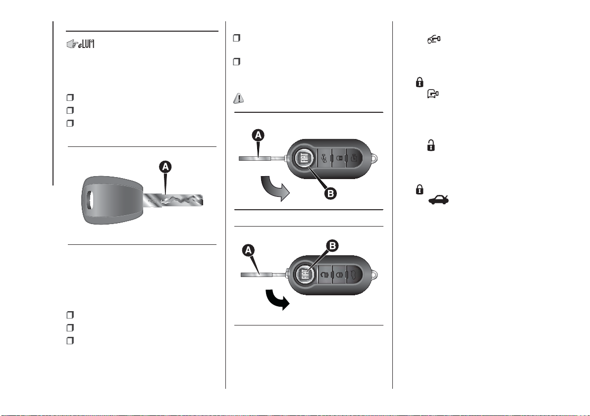
MECHANICAL KEY
The key's metal insert A fig. 1 is fixed.
The key operates:
the ignition device;
the door lock;
opening and closing of the fuel tank
cap.
KNOWING YOUR VEHICLE
1
KEY WITH REMOTE
CONTROL
The metal insert A fig. 2 - fig. 3 retracts
into the handle and operates:
the ignition device;
the door lock;
opening and closing of the fuel tank
cap.
To extract the metal insert, press the
button B fig. 2 - fig. 3.
F0V0003
To refit it in the grip proceed as follows:
hold down button B and turn the
metal insert A;
release button B and turn the metal
insert A completely until the locking
click is heard to ensure correct closure.
1)
2 - Cargo versions
3 - Combi / Panorama versions
F0V0004
F0V0536
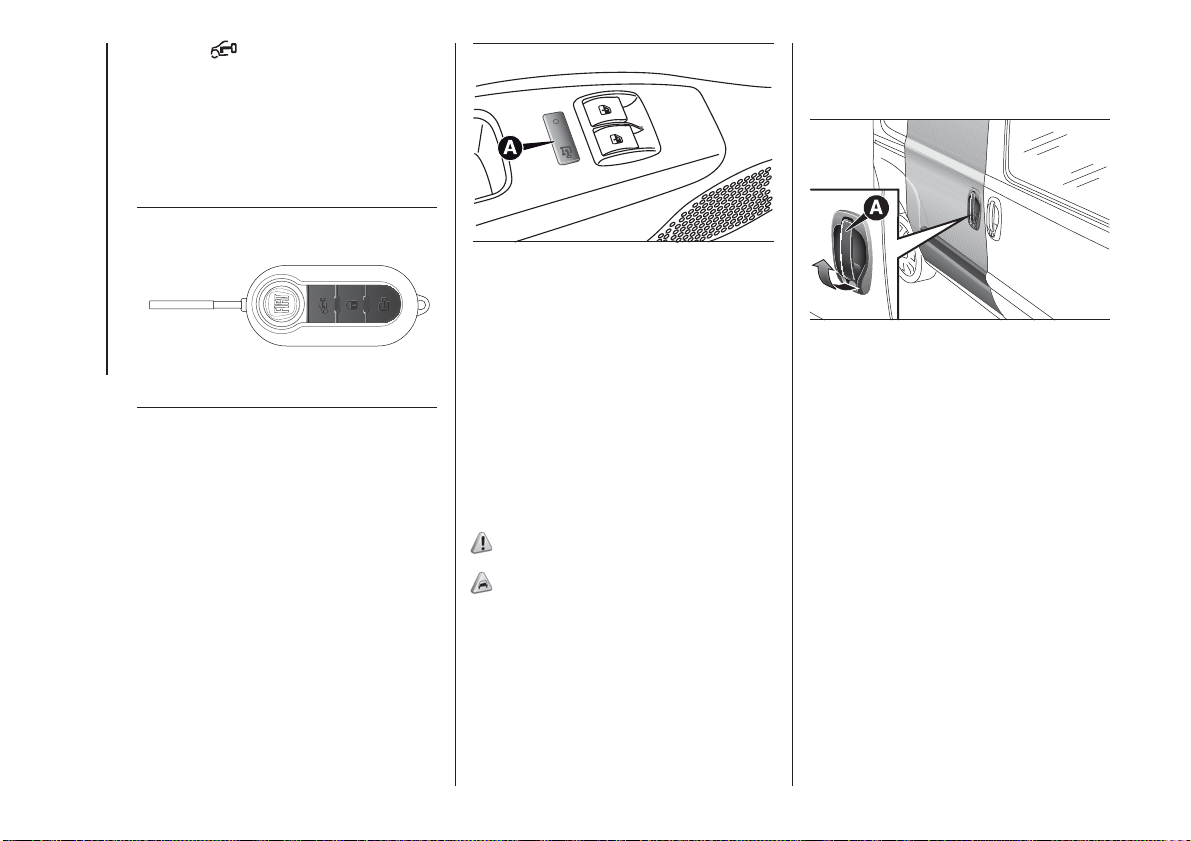
Cargo versions fig. 2
Button
unlocks all the doors
(including the tailgate, the rear swing
doors and the sliding side doors for
versions/markets where provided).
The
button locks all the doors.
Button
unlocks the boot, the rear
swing doors and the sliding side doors
(depending on the version).
Combi / Panorama versions fig. 3
Button
unlocks all the doors
(including the tailgate, the rear swing
doors and the sliding side doors for
versions/markets where provided).
button locks all the doors.
The
Button
unlocks the boot, the rear
swing doors and the sliding side doors
(depending on the version).
DEAD LOCK DEVICE
(for versions/markets, where provided)
This safety device prevents the opening
of the doors from inside the passenger
compartment if there has been a break
in attempt (e.g. a window has been
broken).
The dead lock device therefore offers
the best possible protection against
break in attempts. We recommend
engaging it whenever the vehicle is
parked and left unattended.
10
Turning the device on
The system is automatically enabled on
all the doors by pressing button
twice on the key with remote control.
The direction indicators flash twice to
let you know that the device is active.
If one or more of the doors is not
perfectly shut, the dead lock device will
not be activated, thus preventing a
person getting into the vehicle through
the open door and, on shutting, it,
remaining stuck inside the passenger
compartment.
Turning the device off
The system is disabled automatically on
every door when:
unlocking the doors;
by turning the ignition key to the
MAR position.
2) 3)
2) Once the safe lock system is engaged it
is impossible to open the doors from
inside the vehicle. Before engaging the
system please therefore check that there is
no one left on board.
3) If the remote control battery is flat, the
system can only be turned on by inserting
the metal key in the door lock: in this case,
the device remains active for the rear
doors only.
WARNING
1) Used batteries are harmful to the
environment. You can dispose of them
either in the correct containers as specified
by law or by taking them to a Fiat
Dealership, which will deal with their
disposal.
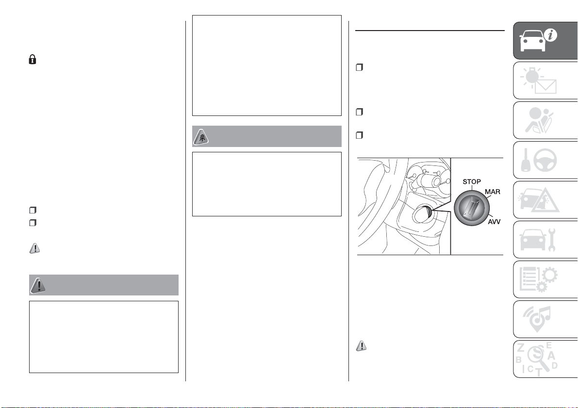
IGNITION DEVICE
The key can be turned to 3 different
positions fig. 4:
STOP: engine off, key extractable,
steering locked. Some electrical
devices (e.g. sound system, central
door locking system, etc.) can operate;
MAR: driving position. All electrical
devices are enabled;
AVV: engine starting (unstable
position).
4
F0V0006
WARNING
1) Button B should only be pressed when
the key is away from the body, in particular
from the eyes and from objects that can
be spoilt (e.g. clothes). Do not leave the
key unattended to avoid the button being
accidentally pressed while it is being
handled, e.g. by a child.
The ignition switch is fitted with an
electronic safety system that requires
the ignition key to be turned back
to STOP if the engine will not start,
before the starting operation can be
repeated.
4) 5) 6) 7)
11
STEERING LOCK
Activation
When the key is at STOP, remove the
key and turn the steering wheel until
it locks.
Deactivation
Move the steering wheel slightly as you
turn the ignition key to MAR.
WARNING
4) If the ignition device has been tampered
KNOWING YOUR VEHICLE
with (e.g. an attempted theft), have it
checked over by a Fiat Dealership before
driving again.
5) Always remove the key when you leave
your vehicle to prevent someone from
accidentally operating the controls.
Remember to engage the handbrake.
Engage first gear if the vehicle is parked
uphill or reverse gear if the vehicle is
parked downhill. Never leave children
unattended in the vehicle.
6) Never extract the key while the vehicle is
moving. The steering wheel will
automatically lock as soon as it is turned.
This also applies to cases in which the
vehicle is towed.
7) It is absolutely forbidden to carry out any
after-market operation involving steering
system or steering column modifications
(e.g.: installation of anti-theft device) that
could badly affect performance and safety,
cause the lapse of warranty and also
result in non-compliance of the vehicle with
type approval requirements.
THE FIAT CODE
SYSTEM
IN BRIEF
This is an electrical engine locking
system which increases protection
against attempted theft of the vehicle.
It is automatically activated when
the key is removed from the ignition
device.
Each key contains an electronic
device which modulates the signal
emitted during ignition by an antenna
built into the ignition device. The
signal, which changes each time the
engine is started, is the “password”,
by means of which the control unit
recognises the key and enables
starting.
1)
12
Irregular operation
If the code has not been recognised
correctly during starting, the
warning light on the instrument
panel turns on accompanied by the
corresponding message on the display
(see the “Warning lights and messages”
chapter).
In this case, turn the key to STOP and
then back to MAR; if the lock
continues, try with the other keys
provided with the vehicle. Contact a
Fiat Dealership if you still cannot start
the engine.
IMPORTANT Each key has its own
code which must be stored by the
system's control unit. Contact a Fiat
Dealership to have new keys (up to 8)
stored with a code.
Activation of the
warning light while
driving
If the warning light turns on, this
means that the system is running a
self-diagnosis (for example due to
a voltage drop).
If the warning light stays on,
contact a Fiat Dealership.
WARNING
1) The electronic components inside the
key may be damaged if the key is
subjected to strong shocks. In order to
ensure complete efficiency of the
electronic devices inside the key, it should
never be exposed to direct sunlight.
DOORS
DOOR CENTRAL
LOCKING/UNLOCKING
Locking from the outside
The doors will only be locked if all doors
are shut. If one or more of the doors is
open after button
the remote control , the direction
indicators will flash quickly for around
three seconds.
You can lock all the doors by turning
the key clockwise in the driver's door.
Pressing the button
control twice rapidly turns on the dead
lock device (see the "Dead lock device"
paragraph).
Door unlocking from the outside
Press the
unlock only the front doors (Cargo
version), to turn on the front ceiling
lights for a limited period and to double
flash the direction indicators.
Press
button and hold it pressed to
remotely unlock the load compartment
(Cargo version), to turn on the rear
ceiling lights for a limited period and to
double flash the direction indicators.
Turn the key anticlockwise in the
driver's door to unlock the front doors
only.
is pressed on
on the remote
button shortly to remotely
13
Press the button briefly to unlock all
the doors (Doblò/Doblò Combi
version), switch on the ceiling lights
temporarily and double-flash the
direction indicators. Turn the key
anticlockwise in the driver's door to
unlock all the doors.
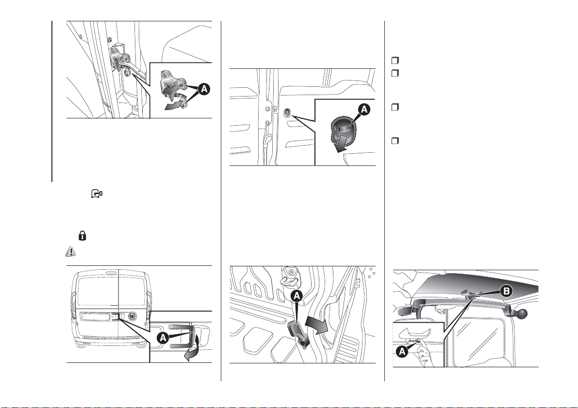
Closing: push the handle A fig. 7
towards the front of the vehicle. Lock
with the key.
KNOWING YOUR VEHICLE
14
5
F0V0046
Unlocking the load compartment
from inside the vehicle (Cargo
version)
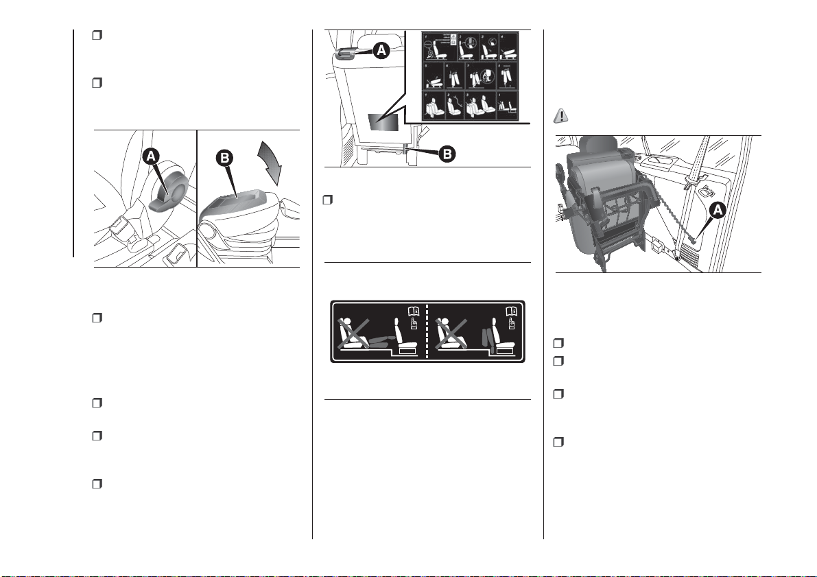
Press button A fig. 6 (Cargo version) to
unlock the load compartment (rear
swing doors/tailgate and sliding side
doors) from inside the vehicle. If the
LED is on, the loading area is locked.
6
F0V0022
SLIDING SIDE DOORS
(for versions/markets, where provided)
On Cargo versions, the sliding side
door is fitted with a spring-loaded latch
that stops the door from opening any
further. To lock it, simply push the door
as far as it will go; to unlock it, pull
forward firmly.
In any case, make sure that the door is
correctly attached to the device that
holds it fully open.
8) 9) 10) 11)
2)
Opening/closing from
outside
Opening: turn the key in the lock and
pull handle A fig. 7 in the direction
shown by the arrow, then slide the door
towards the rear of the vehicle until it
locks into place and can go no further.
7
F0V0085
Opening/closing from
the inside (Doblò/Doblò
Combi versions)
Opening: push switch A fig. 8 to unlock
the door, then pull the handle and
slide the door towards the rear of the
vehicle until it can go no further.
Closing: push switch A fig. 8 to release
the door and then push it towards
the front of the vehicle.
CHILD SAFETY DEVICE
This system prevents the sliding side
doors being opened from the inside.
The device fig. 10 can be engaged only
with the sliding side door open:
position 1 - device engaged (door
locked);
position 2 - device not engaged (door
may be opened from the inside).
8
F0V0382
The device remains engaged even if the
doors are electrically unlocked.
12)
9
F0V0186
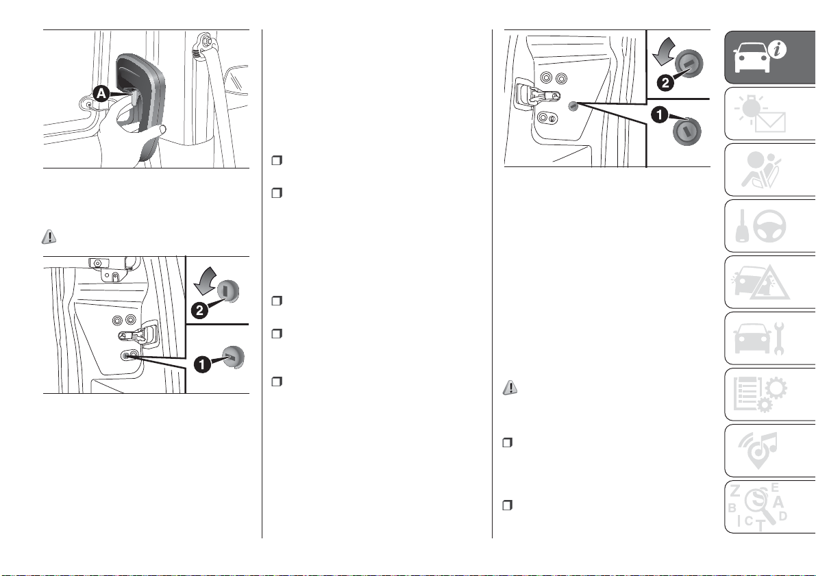
KEY EMERGENCY LOCK
(KEL) DEVICE
The sliding side doors are provided with
a device for locking all the doors using
the lock in the case of a power fault.
The device can be engaged, with
the sliding side doors open, as follows
fig. 10:
position 2: device not engaged
(doors released)
position 1: device engaged (fit the
metal insert of the ignition key in its seat
and rotate clockwise), door locked
The device is released and thus the
doors can be opened as follows: in the
event that electrical operation is
restored:
by remote control
or
open a front door by inserting the
key into the key pawl. in the event that
electrical operation is restored;
opening the driver side door by key
pawl and the other doors (passenger's
side and sliding side door) pulling the
inner handle.
10
F0V0383
DOUBLE REAR WING
DOORS
(for versions/markets, where provided)
The double rear swing doors are fitted
with a link system that stops them
when they have opened to an angle of
approximately 90 degrees.
To open them wider to an angle of 180
degrees, push the locking device A
fig. 11 (one on each side) as shown in
the diagram and simultaneously open
the doors.
13)
Using the key latch on the door, you
can do the following:
for Cargo versions with wing door:
centrally unlock the load compartment
(sliding side doors + rear wing doors),
centrally lock all the doors;
for Doblò/Doblò Combi versions
with swing door: local unlocking/
locking.
15
11
Opening/closing the first
swing door from the
outside
To open the door, turn the metallic
KNOWING YOUR VEHICLE
insert of the key in the lock or press
button
on the remote control and
then pull handle A fig. 12 in the
direction of the arrow. To close the
door, turn the key in the lock or press
button on the remote control.
the
14)
F0V0067
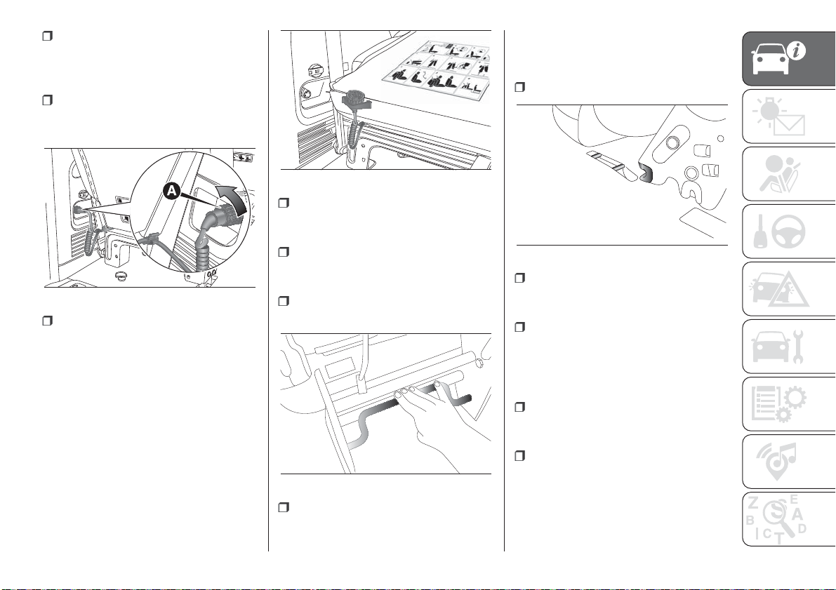
Emergency opening of
the first swing door
from the inside
From inside, use device A fig. 13.
13
F0V0080
Opening the second
swing door
After having opened the first door, pull
handle A fig. 14 in the direction shown
by the arrow.
IMPORTANT Pull handle A fig. 14 only
in the direction shown in the diagram.
FIXED WINDOW
(for versions/markets, where provided)
Using the fixed window:
Open the swing doors;
Push lever A fig. 15 downwards,
ensuring that it is held down until the
lock goes beyond the crossmember;
Open using both hands, making
sure to aid the fixed window opening by
using handle B fig. 15;
To close, pull the fixed window
downwards using the suitable handle
B.
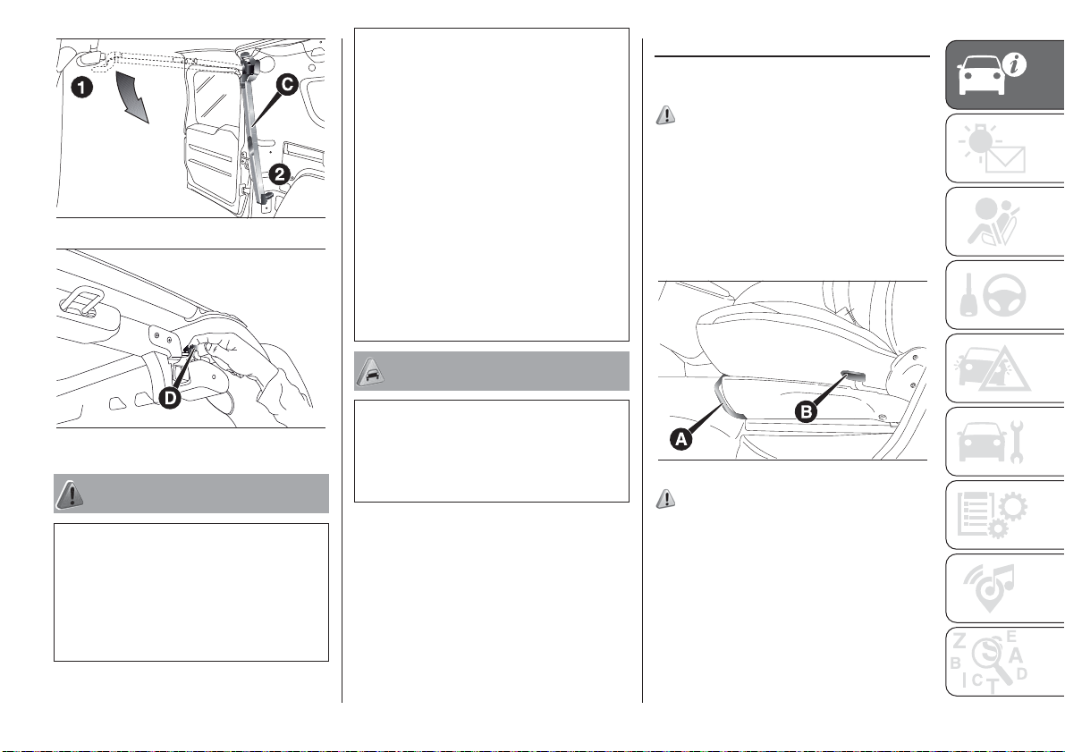
IMPORTANT The fixed window remains
open up to a speed of 110 km/h.
With the fixed window open it is
possible, if necessary, to lower the
crossmember C, accompanying it from
position 1 to position 2 fig. 16.
To release and lower the crossmember,
act, with rear doors open, on lever D
fig. 17.
16
12
F0V0518
14
F0V0078
15
F0V0526
10) Do not leave the sliding side door open
when the vehicle is parked on a gradient.
A knock could release the latch leaving the
door free to move forward.
11) Before leaving the vehicle parked with
sliding doors open, always check that
the latch is engaged.
12) Always use this device when carrying
children.
13) The spring-loaded system is designed
16
F0V0527
for optimum usage. Accidental knocks
or a strong gust of wind may release the
springs, forcing the doors to close.
14) When closing, shut the right hand
swing door fully before you close the left
hand swing door. Never shut the two doors
at the same time.
SEATS
DRIVER’S SEAT
(for Cargo versions, where provided)
15)
Longitudinal adjustment
Lift the lever A fig. 18 and push the seat
forwards or backwards: in the driving
position your arms should be slightly
bent and your hands should rest on the
steering wheel rim.
WARNING
2) Make sure that the left sliding side door
17
F0V0528
WARNING
is all closed before refuelling to prevent
damage to the door and to the sliding
locking system with fuel filler cap open,
activated during refuelling operations.
18
16)
F0V0210
8) Before opening a door, ensure that you
can do it in conditions of safety.
9) You must not open the left-hand sliding
side door with the fuel cap open while
refuelling. Check that the fuel cap is closed
while opening/closing the sliding side
door to avoid damage.
Reclining backrest adjustment
Lift lever B fig. 18 and, slightly
detaching the back from the backrest,
accompany the movement of the
backrest until it is in the desired
position.
17
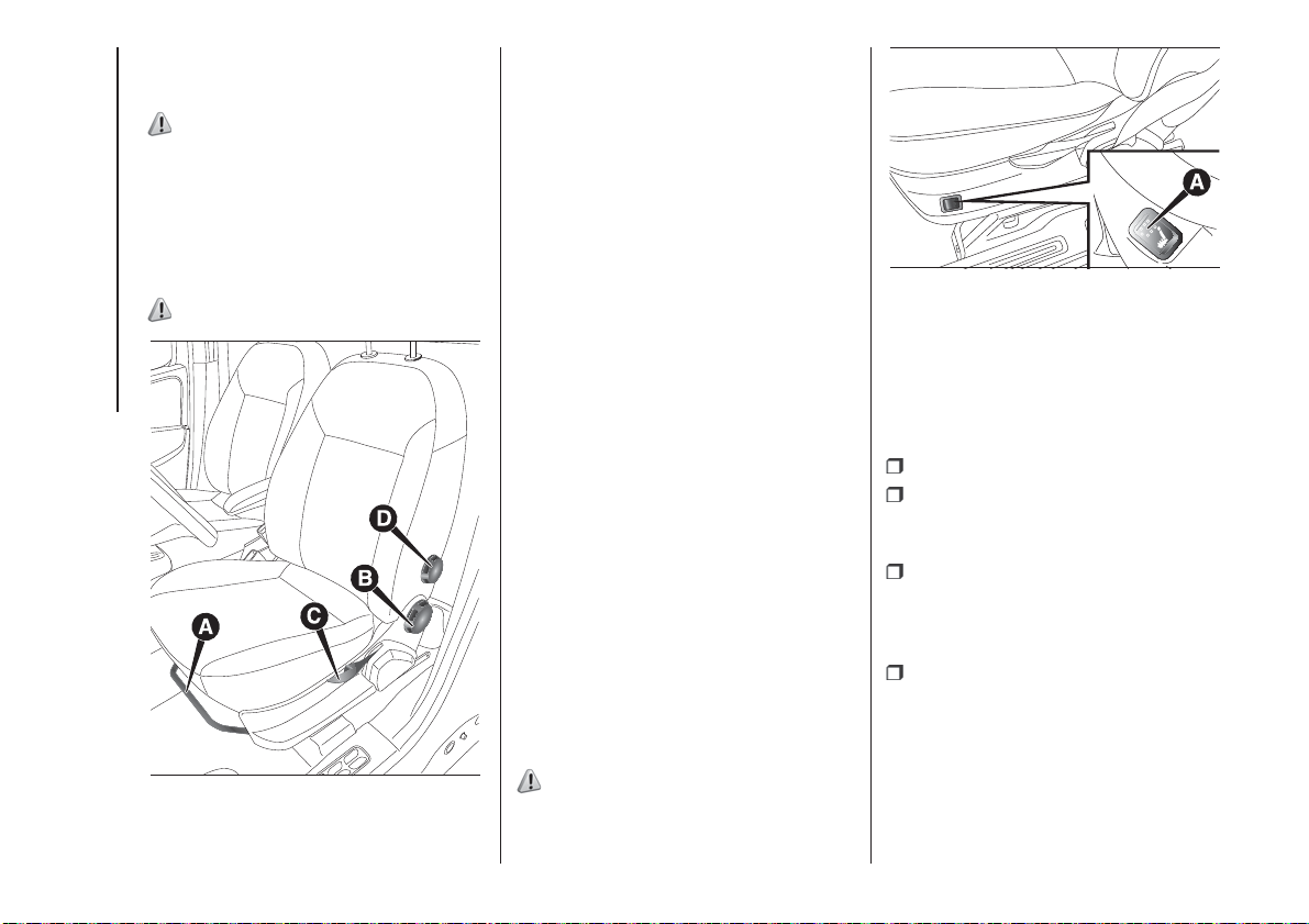
DRIVER’S SEAT
(for Doblò/Doblò Combi/Cargo
versions, where provided)
15)
Lengthwise adjustment
Lift lever A fig. 19 and push the seat
forwards or backwards: in the driving
position your arms should rest on
the steering wheel rim.
16)
KNOWING YOUR VEHICLE
19
F0V0013
Backrest angle adjustment
Turn the knob B fig. 19
Driver seat height adjustment
(for versions/markets, where provided)
Operate lever C fig. 19 to lift or lower
the rear part of the cushion to achieve
the most comfortable driving position.
IMPORTANT Adjustment must be
carried out only when seated in the
relevant seat.
Driver seat lumbar adjustment
(for versions/markets, where provided)
Turn knob D fig. 19 to adjust the
backrest support.
Heated seats
(for versions/markets, where provided)
With the key turned to MAR, press
button A fig. 20 to switch the function
on/off.
When the function is enabled, the LED
on the button turns on.
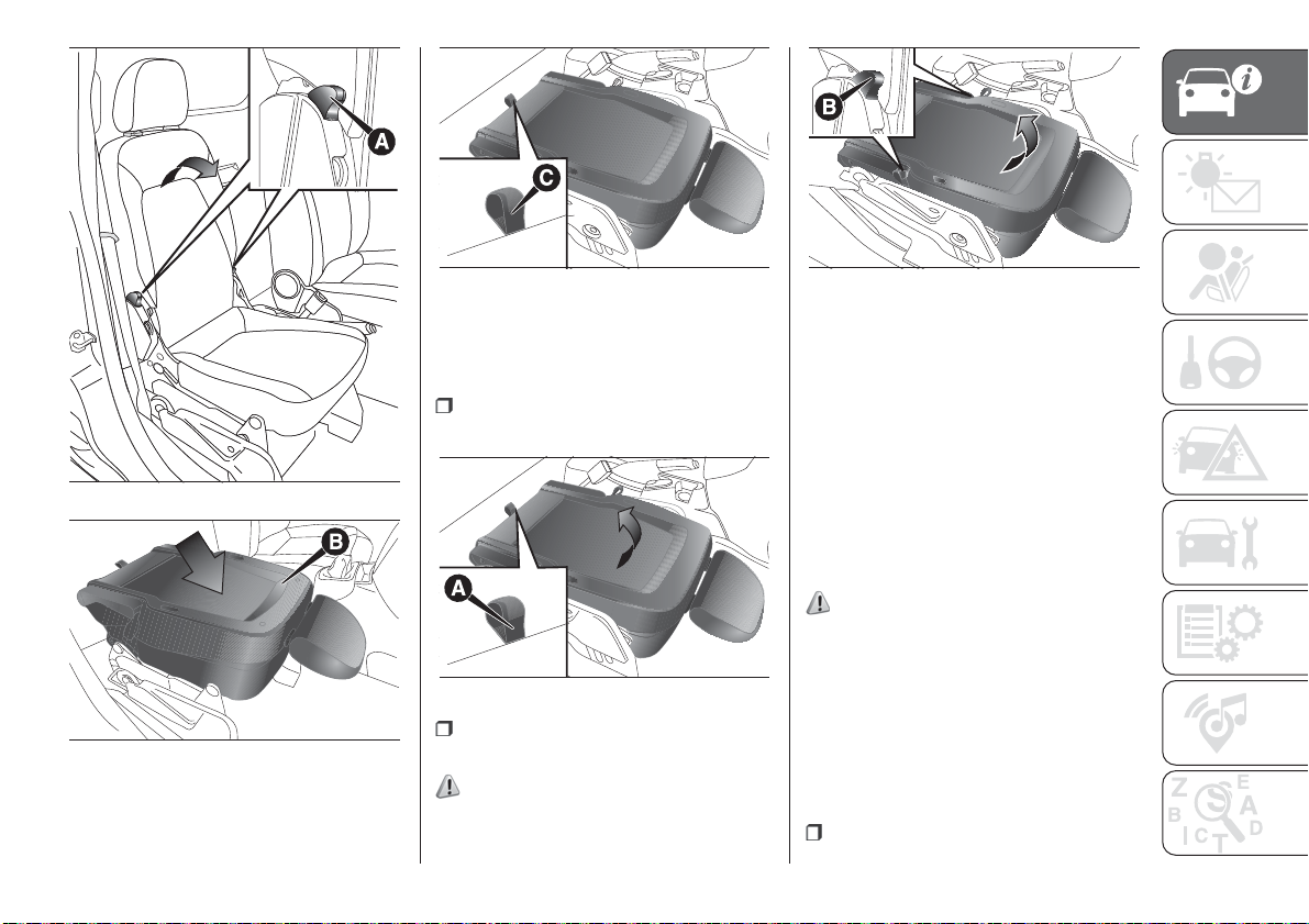
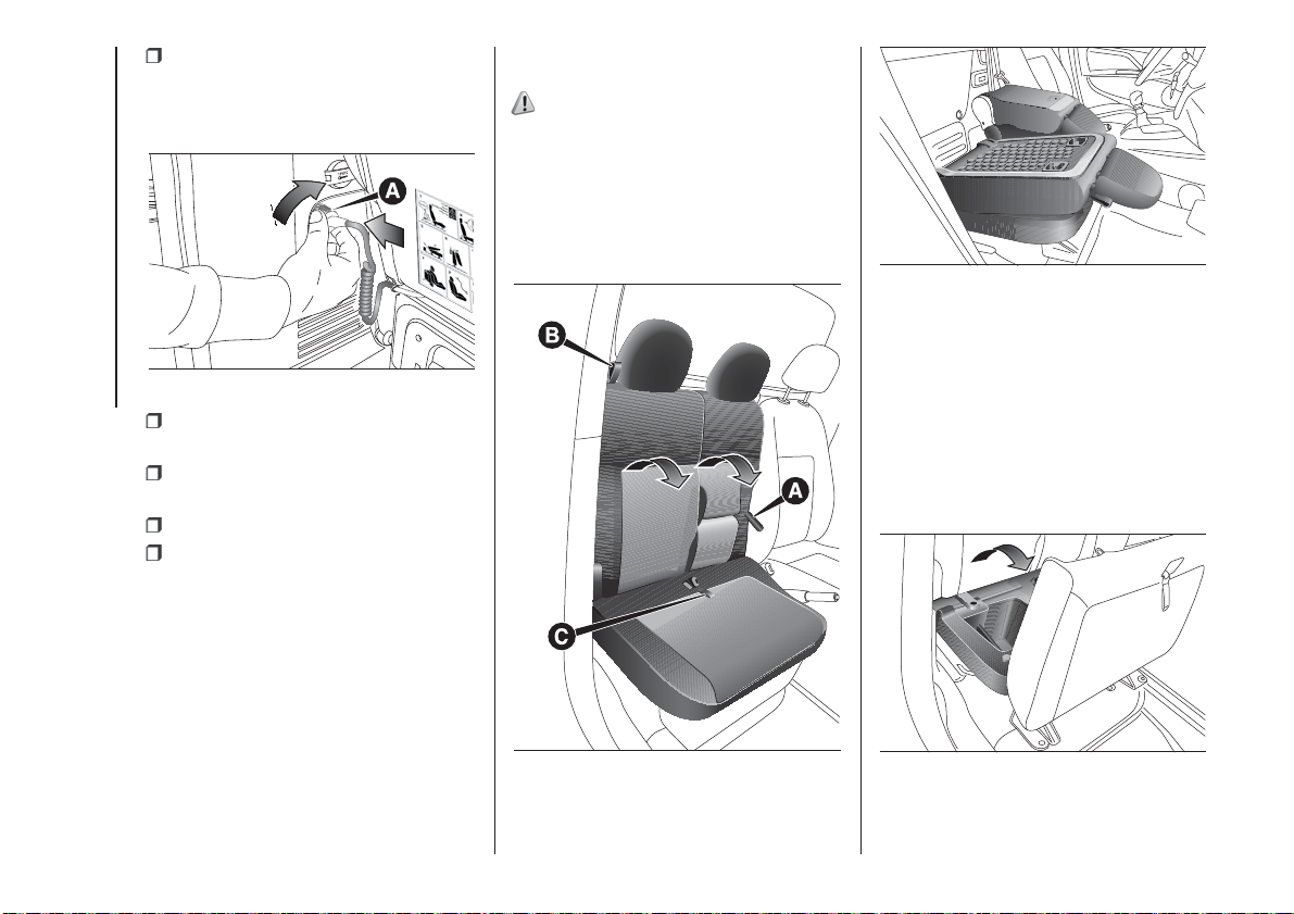
FOLDAWAY PASSENGER
SEAT
(for versions/markets, where provided)
The passenger seat can be folded
away on some Cargo versions.
17)
20
F0V0208
Completely retract the seat for a total
folding down avoiding interference with
the dashboard.
Seat folding
To fold the seat, proceed as follows:
open the passenger side door;
pull levers A and fold the backrest
forwards in the direction indicated
by the arrow;
then push the backrest B fig. 22
down: the seat is now completely
folded over on itself into the "table"
position;
pull tab C fig. 23 and push the
backrest down further: the seat is now
completely folded away.
18
23
F0V0144
25
F0V0146
Repositioning the seat
To return the seat back to its normal
position, proceed as follows:
take tab A fig. 24 and lift the
backrest up;
ACCESS TO THE REAR
SEATS
(Doblò and Doblò Combi versions)
To access the rear seats, open one of
the sliding side doors (see "Doors"
in this section).
FOLDING TABLE SEAT
21
F0V0142
(Doblò and Doblò Combi versions,
where provided)
On some versions the seat can be
folded into a table position.
20)
Completely retract the seat in table
position for a total folding down
24
F0V0145
avoiding interference with the
dashboard.
operate levers B fig. 25 and further
22
F0V0143
lift the seat upwards.
18) 19)
IMPORTANT Move the seat only when
there are no rear passengers.
Seat folding
Open the passenger side door;
19
Operate lever A fig. 26 and fold the
backrest forwards in the direction
indicated by the arrow;
Push the backrest B fig. 26 down:
the seat is now completely folded over
on itself into the "table" position.
NOTE As shown in fig. 29, you do not
need to disconnect electrical connector
A when tilting the seat forward as the
spiral cable does not interfere with
the seat movement.
21)
KNOWING YOUR VEHICLE
20
26
F0V0201
Repositioning the seat:
operate lever A fig. 26 and lift the
backrest upwards.
rd
3
ROW SEAT
MOVEMENTS
Proceed as follows:
completely lower the rear seat head
restraints;
move the seat belt to the side,
making sure that it is fully extended and
not twisted;
lift lever A fig. 27 retaining the
backrest and fold the latter forwards.
When you lift the lever, you will see
a red band.
27
F0V0633
pull the tape B fig. 27 behind the
seat backrests and fold the seats and
the backrests forwards, as shown in fig.
28.
28
F0V0408
NOTE On the split seats, there are
rubber bands on the lower edge of the
cushion so you can attach the folded
seat to the 2nd row rear seat head
restraint rods (see the label shown on
the backrest of the seat fig. 27).
29
F0V0720
3rdROW SEAT REMOVAL
Proceed as follows:
remove the rear seat head restraints;
remove the rolling curtain from its
housing;
move the seat belt to the side,
making sure that it is fully extended and
not twisted;
lift lever A fig. 27 retaining the
backrest and fold the latter forwards.
When you lift the lever, you will see
a red band.
identify the electric connection of the
seat fig. 30 connected to the vehicle in
the left side zone (for the left seat) or
in the right side zone (for the right seat);
turn ring A on the seat connection
anticlockwise (until it locks), pull it
towards you and disconnect the wire;
rd
3
ROW SEAT
REPOSITIONING
Proceed as follows:
insert the hooks in the floor fig. 33;
30
F0V0631
secure the connection with the
elastic tape fig. 31 at the bottom left (for
the left seat) or bottom right (for the
right seat) of the seat backrest;
IMPORTANT Always disconnect the
connection and fasten it to the seat
using the dedicated tape, to prevent it
from being damaged when moving
the seat.
NOTE Always reconnect the electrical
connection for the two 3
rd
row seats
when they are refitted in the vehicle.
31
F0V0632
pull the tape B fig. 27 behind the
seat backrests and fold the seats and
the backrests forwards;
position the head restraint using the
openings under the cushion to insert
the rods;
push the lever as illustrated in fig.
32;
32
F0V0206
remove the seat from the
attachments on the floor.
33
F0V0207
push the lever as illustrated in fig. 32
and pull it to make sure that the seat
is still correctly secured;
identify the electric connection of the
seat constrained by the elastic tape
fig. 31 present in the left side zone (for
the left seat) or in the right side zone
(for the right seat) of the backrest;
pull the elastic tape fig. 31
and remove the electric connection
from the seat;
extend the wiring exiting from the
seat to the connection of the vehicle
located in the left side zone (for the left
seat) or the right side zone (for the
right seat) fig. 34;
21
connect the connection of the seat
A to the connection on vehicle and turn
the ring present on the seat connection
clockwise (until it locks);
34
KNOWING YOUR VEHICLE
withdraw the head restraint under
the cushion;
fold the cushion and the backrest
over;
reposition the head restraint;
reposition the rolling curtain in its
housing.
IMPORTANT Make sure that the seat is
properly secured to the fastenings on
the floor and that the lever A fig. 27
is tightened (red band not visible).
F0V0634
FRONT BENCH
(for versions/markets, where provided)
15)
Some versions feature a front bench
with central and side passenger
backrests that fold down to a table.
To fold the backrests, pull the tabs A or
B fig. 35 to recline the central or side
backrest portion fig. 36.
36
F0V0551
IMPORTANT Before folding down the
central backrest, you need to
completely lower the head restraint to
prevent it from interfering with the
gear lever in certain driving conditions.
By pulling the tab C fig. 35 you can
lift the single central and side place seat
to access an object compartment fig.
37.
22
35
F0V0550
The central backrest features a
retaining clip that can be used to hold
documents.
37
F0V0552
WARNING
15) All adjustments must be made with the
vehicle stationary.
16) Once you have released the
adjustment lever, always check that the
seat is locked on the guides by trying
to move it back and forth. If it is not locked,
the seat may move unexpectedly and
make you lose control of the vehicle.
17) Close the dashboard console before
folding the retractable front passenger seat
to avoid damage.
18) When the passenger seat is folded
away, the space created cannot be used
for loading. When the vehicle is in motion,
you are therefore advised to remove or
secure any objects that might interfere with
the driver.
19) If there is no partition between the cab
and the load compartment, tall objects
or packages may take up part of the
passenger area. Make sure that these
items are well secured by using the
available hooks and that they cannot
interfere with the driver.
20) Close the dashboard console before
folding the front passenger seat to form
a table to avoid damage.
21) While travelling, before using the third
row seats, make sure that the second
row seats are in running position and well
anchored (see the specific label fig. 28.
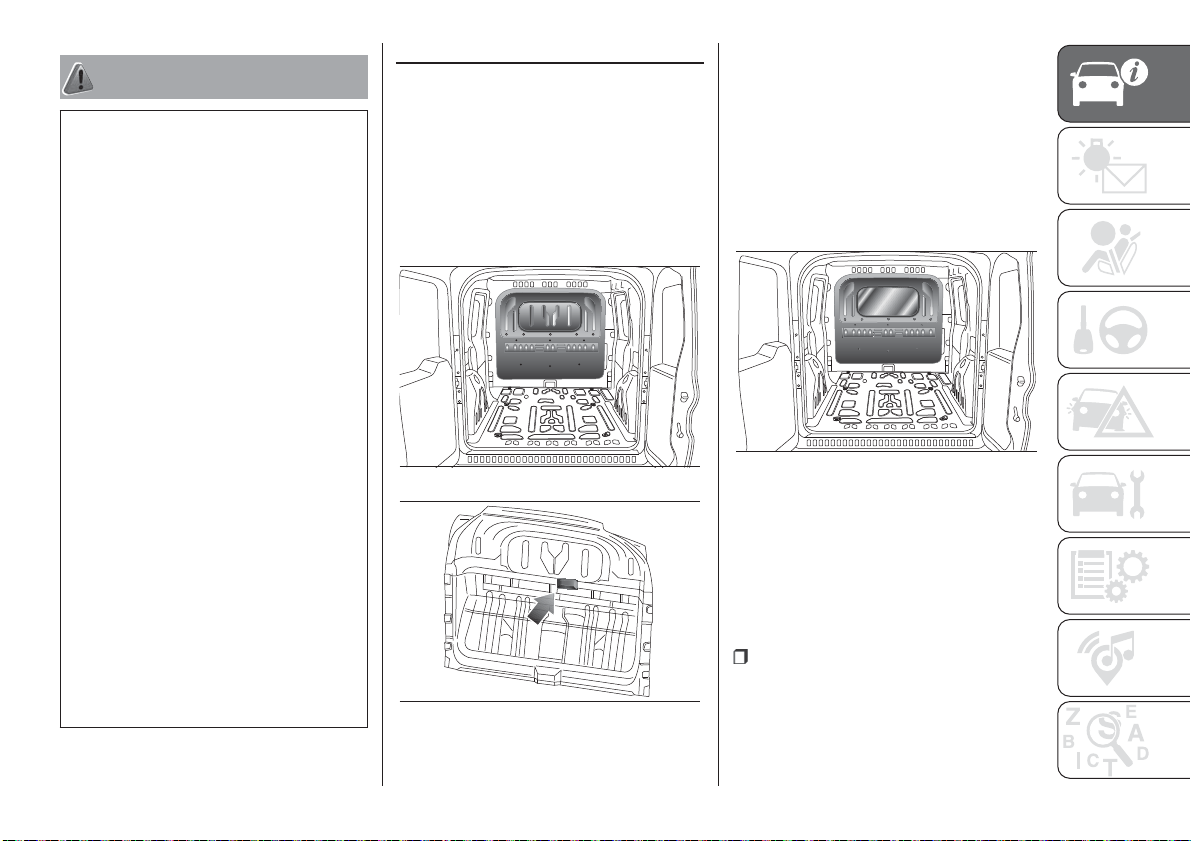
PARTITIONS
FIXED PANEL PARTITION
(for versions/markets, where provided)
Separates the passenger area from
the load compartment fig. 38.
For versions fitted with three-seater
front bench seat, the guard has the
retractor fig. 39 for the central rear seat
belt.
38
39
F0V0102
F0V0620
FIXED GLAZED
PARTITION
(for versions/markets, where provided)
This has a central window so you
can keep an eye on your load fig. 40.
For versions fitted with three-seater
front bench seat, the guard has the
retractor fig. 39 for the central rear seat
belt.
40
F0V0103
SPLIT ROTATING
PARTITION
(for versions/markets, where provided)
Should it be necessary to transport
long, bulky loads, the passenger side
panel can be removed and fixed to the
driver’s side, as follows fig. 41:
lay the foldaway passenger seat flat
(see previous pages);
23
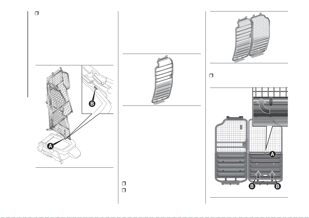
from inside the load compartment,
rotate the locking hook, remove the
panel, releasing it from the 4 passenger
side pins, and fit the panel on the
driver’s side pins B, then rotate locking
hook A.
To put the partition back in its normal
position, follow the same procedure
in reverse.
KNOWING YOUR VEHICLE
DRIVER’S SIDE TUBULAR
PARTITION
(for versions with 3-seater bench)
On versions with 3-seater bench there
is a fixed ladder fig. 42 which protects
the driver if the load transported is
unstable.
43
raise the panel, releasing it from the
pins B fig. 44;
F0V0578
24
42
F0V0577
PARTITION WITH
COMPLETE GRILLE
(for versions/markets, where provided)
On versions with 3-seater bench, a
complete partition fig. 43 may be
requested to protect all occupants of
the vehicle.
If long loads need to be transported,
the passenger side panel can be
41
F0V0219
dismantled and placed over the driver
side panel, proceeding as follows:
fold the passenger seat away;
from inside the load compartment,
rotate the locking hook A fig. 44 90°
anticlockwise;
44
F0V0602
arrange the panel, placing it over
that on the driver side, aligning the
holes C fig. 45 on the removed panel
with the locking pins D fig. 45 on the
driver side panel.
45
F0V0603
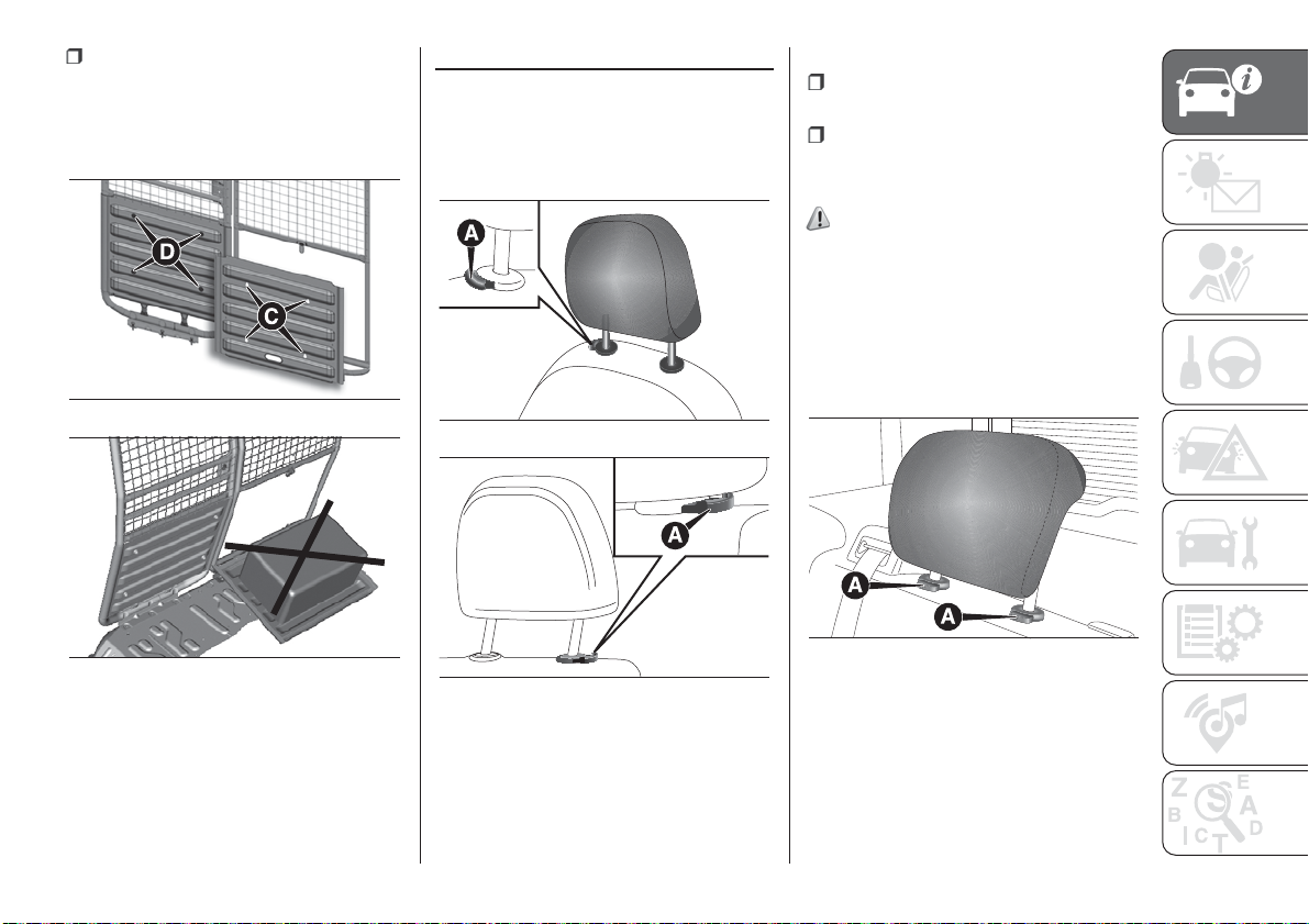
HEADRESTS
FRONT
The head restraints are heightadjustable and lock into the desired
position automatically.
47
Adjustment
upward adjustment: raise the head
restraint until it clicks into place.
downward adjustment: press button
A fig. 47 - fig. 48 and lower the head
restraint.
22) 23)
REAR
(for versions/markets, where provided)
To use them, lift them up.
To put the headrests away, press
buttons A fig. 49 and push them down
into the backrest.
F0V0105
46
F0V0604
IMPORTANT Do not place loads on the
rotated panel fig. 46 and do not leave
the panel in rotated position to avoid
damage.
48 - Front bench version
F0V0553
49
F0V0119
To extract the head restraints, raise
them until you hear the click (which
indicates they are in the position of
use).
IMPORTANT If the rear seats are used,
always set the head restraints in the
"completely raised" position.
25
WARNING
22) All adjustments must be carried out
only with the vehicle stationary and the
engine off. Head restraints must be
adjusted so that the head, rather than the
neck, rests on them. Only in this case
they can protect your head correctly.
23) To take best advantage of the
protection provided by the headrest, adjust
the seat back so that you are sitting up
straight and your head is as close to the
headrest as possible.
KNOWING YOUR VEHICLE
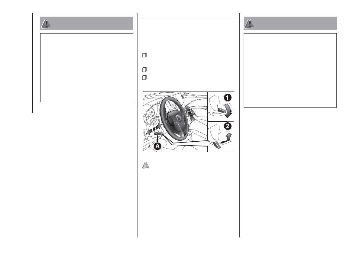
STEERING WHEEL
The height and axial position of the
steering wheel can be adjusted on all
versions.
To adjust, proceed as follows:
release lever A fig. 50 by pushing it
forwards (position 1);
adjust the steering wheel;
lock lever A fig. 50 by pulling it
towards the steering wheel (position 2).
WARNING
24) All adjustments must be carried out
only with the vehicle stationary and the
engine off.
25) It is absolutely forbidden to carry out
any after-market operation involving
steering system or steering column
modifications (e.g. installation of anti-theft
device) that could adversely affect
performance, invalidate the warranty, cause
serious safety problems and also result in
the car not meeting type-approval
requirements.
26
50
24) 25)
F0V0014

REAR VIEW
MIRRORS
INTERIOR MIRROR
(for versions/markets, where provided)
The mirror is fitted with a safety device
that causes its release in the event of
a violent impact with the passenger.
Lever A fig. 51 can be used to move
the mirror to two different positions:
normal or antiglare.
51
Some versions may feature an internal
child surveillance mirror B fig. 52.
DOOR MIRRORS
Manual mirror folding
When required (for example when the
shape causes difficulty in narrow
spaces), the mirrors can be folded by
moving them from position A fig. 53
to position B.
26)
F0V0125
52
53
F0V0542
F0V0084
Manual adjustment
From inside, use device A fig. 54.
Electric adjustment
(for versions/markets, where provided)
Door mirrors can be adjusted only if the
ignition key is in MAR position.
Proceed as follows:
select the required mirror with switch
A fig. 55 (right or left);
54
F0V0120
move switch A to position B and
manipulate it to adjust the left door
mirror;
turn switch A to position D and
manipulate it to adjust the right door
mirror.
Once you have finished the adjustment,
return switch A to intermediate locking
position C.
Electric folding
Door mirrors can be folded only if the
ignition key is in MAR position.
Bring switch A fig. 55 to position E to
fold the mirrors in the closed position.
Bring switch A to position C to move
the mirrors back to the driving position.
27
55
WARNING
26) When driving, the mirrors shall always
KNOWING YOUR VEHICLE
be in position A fig. 53. As door mirrors are
curved, they may slightly alter the
perception of distance.
F0V0560
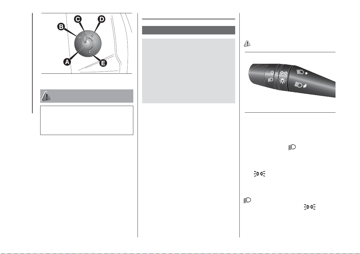
EXTERIOR LIGHTS
IN BRIEF
The left stalk includes the controls for
the exterior lights.
The external lights can only be
switched on when the ignition key is
at MAR.
The instrument panel and the various
dashboard controls will come on
with the external lights.
DAYTIME RUNNING
LIGHTS (DRL)
(for versions/markets, where provided)
With the key in MAR position and
the ring nut turned to O position, the
daytime lights switch on automatically;
the other lights and the internal lighting
remain off. In some markets, the
automatic operation of the daytime
running lights can be activated/
deactivated via the display menu (see
"Digital/multifunction display" in this
section). If the daytime running lights
are deactivated, no light comes on
when the ring nut is turned to O.
When the daytime running lights are on,
activating the direction indicators will
turn off the corresponding headlight’s
daytime running light (D.R.L.).
27)
56
F0V0515
DIPPED HEADLIGHTS/
SIDE LIGHTS
With the ignition key turned to MAR,
turn the ring nut to
. If dipped
headlights are activated, the daytime
running lights switch off and the side
lights and dipped headlights switch on.
The
warning light switches on in
the instrument panel. When the ignition
key is turned to STOP or removed
and the ring nut is turned from O to
, all the side lights and the number
plate lights come on. The
warning
light will come on in the instrument
panel.
28
 Loading...