

Page 1

Page 2
Dear Customer,
Thank you for choosing Fiat and congratulations on your choice of a Fiat Doblò.
We have written this handbook to help you get to know all the features of your vehicle and use it in the best possible way.
You should read it right through before taking to the road for the first time. You will find information, tips and important warnings regarding the driving of your vehicle to help you get the most from the technological features of your Fiat Doblò.
Please read the warnings and instructions the bottom of the page carefully; these are marked with the following symbols:
personal safety;
condition of the vehicle;
environmental protection.
The enclosed Warranty Booklet lists the services that Fiat offers its customers:
❒
the Warranty Certificate with terms and conditions for maintaining its validity
❒
the range of additional services available to Fiat customers.
Enjoy the read. Happy motoring!
This Owner’s Handbook describes all versions of the Fiat Doblò;
please consider only the information relevant to your version,
engine and configuration.
Page 3
READ THIS CAREFULLY!
REFUELLING
Petrol engines: only refuel with unleaded petrol with
an octane rating (RON) of no less than 95 conform-
K
ing to the European specification EN 228.
Diesel engines: only use diesel fuel for motor vehicles
conforming to the European specification EN 590. The
use of other products or mixtures may damage the
engine beyond repair and consequently invalidate the
warranty, depending on the damage caused.
STARTING THE ENGINE
Petrol engines: make sure that the handbrake is engaged, place the gear lever in neutral, fully depress the
clutch without depressing the accelerator, then turn
the ignition key to AVV and release it as soon as the
engine has started.
Diesel engines: turn the ignition key to MAR and wait
until the warning lights Y (or symbol on the display)
and mgo off. Then, turn the ignition key to AVV and
release it as soon as the engine has started.
PARKING ON FLAMMABLE MATERIAL
The catalytic silencer reaches high temperatures dur-
ing operation. Do not park the on grass, dry leaves,
pine needles or other flammable material as this constitutes a fire hazard.
ELECTRICAL ACCESSORIES
If, after buying the vehicle, you decide to add electrical accessories (with the risk of gradually draining the
쇵
battery), visit the Fiat Service Network. They can calculate the overall electrical requirement and check that
the vehicle’s electrical system can support the required
load.
CODE card
Keep it in a safe place, not in the vehicle. You should
have the electronic code from the CODE card with
you at all times.
SCHEDULED MAINTENANCE
Correct maintenance is essential for ensuring the vehicle stays in tip-top condition and retains its safety
features, its environmental friendliness and low running costs for a long time to come.
THE OWNER’S HANDBOOK CONTAINS…
... information, tips and important warnings on the correct use and maintenance of your vehicle over time as
well as safe driving tips. Pay special attention to the
symbols "(personal safety) #(protecting the environment) ! (risk of serious damage to the vehicle).
RESPECTING THE ENVIRONMENT
The vehicle is fitted with a system that allows continuous diagnosis of the emission-related components in
order to help protect the environment.
Page 4
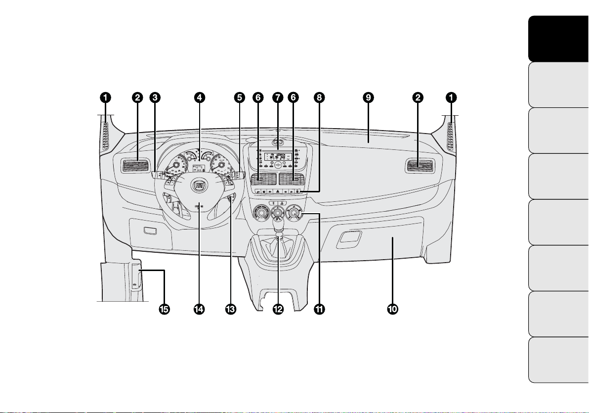
DASHBOARD
KNOW YOUR VEHICLE
KNOW
YOUR
VEHICLE
The presence and position of the controls, the instruments and the indicators may vary according to the versions.
Fig. 1
F0V0185m
1. Diffuser for sending air to the side windows – 2. Adjustable and directable air diffuser – 3. Exterior lights control lever
– 4. Instrument panel and warning lights – 5. Windscreen wiper/rear windscreen wiper/trip computer control lever – 6. Adjustable and directable air diffusers – 7. Sound system (for versions/markets where provided) – 8. Control Panel – 9. Passenger
air bag (for versions/markets where provided) – 10. Glove compartment – 11. Heating/ventilation/climate control system controls – 12. Gear stick – 13. Starting device – 14. Driver’s air bag – 15. Bonnet release lever.
SAFETY
STARTING
AND
DRIVING
WARNING
LIGHTS AND
MESSAGES
IN AN
EMERGENCY
SERVICING
AND
MAINTENANCE
TECHNICAL
SPECIFICATIONS
INDEX
3
Page 5

KNOW
YOUR
VEHICLE
SAFETY
STARTING
AND
DRIVING
SYMBOLS
Special coloured labels have been attached near or on
some of the components of your vehicle. These labels bear
symbols that draw your attention to the precautions required when handling the component in question.
A plate summarising these symbols can be found under
the engine bonnet.
THE FIAT CODE SYSTEM
This is an electrical engine immobiliser system which increases protection against attempted theft of the vehicle.
It is automatically activated when the ignition key is extracted.
Each key contains an electronic device which modulates
the signal emitted during starting by an antenna built into
the starting device. This signal is the ‘password’ which
changes at each starting and which the control unit uses
to recognise the key and enable starting.
WARNING
LIGHTS AND
MESSAGES
IN AN
EMERGENCY
SERVICING
AND
MAINTENANCE
TECHNICAL
SPECIFICATIONS
INDEX
4
OPERATION
Each time the vehicle is started by turning the ignition key
to MAR, the Fiat CODE system control unit sends a recognition code to the engine management control unit to deactivate the immobiliser.
The code is only sent if the Fiat CODE system control
unit has recognised the code transmitted by the key.
Each time the ignition key is turned to STOP, the Fiat
CODE system deactivates the functions of the engine management control unit.
If, during starting, the code is not correctly recognised,
warning light
In this case, turn the key to STOP and then to MAR; if it
is still locked, try again with the other keys that come with
the vehicle. Contact a Fiat Service Network if you still
cannot start the engine.
lights up in the instrument panel.
Y
Page 6
Warning light
❒
If the warning light Ycomes on, this means that the
comes on when driving
Y
system is running a self-diagnosis (owing to a voltage
drop, for example).
❒
If the warning light Ystays on, contact the Fiat Service Network.
The electronic components inside the key
may be damaged if the key is subjected to
sharp knocks.
THE KEYS
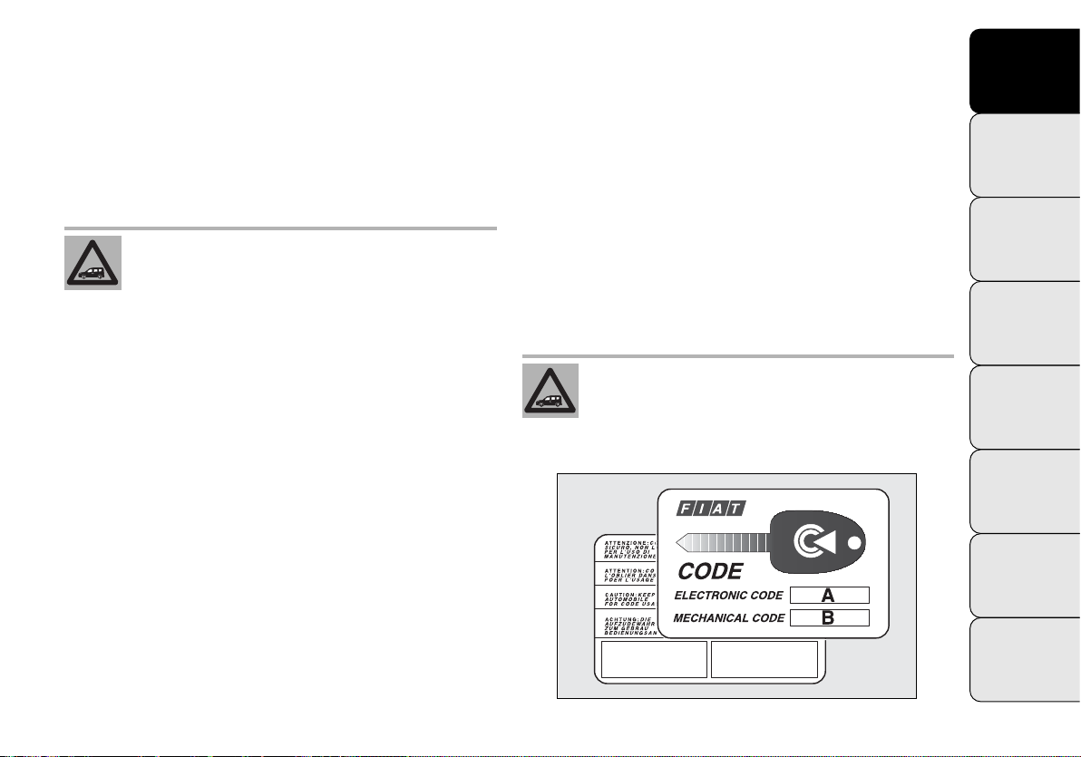
CODE CARD fig. 2
(for versions/markets where provided)
The vehicle is delivered with duplicate ignition keys and
with the CODE card, which bears the following:
A the electronic code;
B the mechanical key code to be given to the Fiat Ser-
vice Network when ordering duplicate keys.
WARNING In order to ensure complete efficiency of the
electronic devices inside the keys, they should never be
exposed to direct sunlight.
All the keys and the CODE card must be
handed over to the new owner when selling the vehicle.
KNOW
YOUR
VEHICLE
SAFETY
STARTING
AND
DRIVING
WARNING
LIGHTS AND
MESSAGES
IN AN
EMERGENCY
SERVICING
AND
MAINTENANCE
fig. 2
TECHNICAL
SPECIFICATIONS
INDEX
F0V0104m
5
Page 7
KNOW
VEHICLE
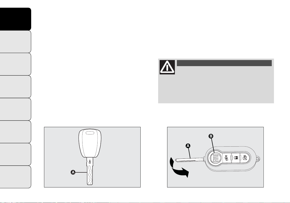
MECHANICAL KEY fig. 3
The metal insert A operates:
YOUR
❒
❒
SAFETY
❒
the starting device;
the door locks;
opening and closing the fuel plug.
To re-house it, proceed as follows:
❒
hold down button B and move the metal insert A;
❒
release button B and turn the metal insert A until you
hear the proper locking click.
STARTING
DRIVING
WARNING
LIGHTS AND
MESSAGES
KEY WITH REMOTE CONTROL fig. 4
(for versions/markets where provided)
AND
The metal insert A operates:
❒
the starting device;
❒
the door locks;
❒
opening and closing the fuel tank plug.
To extract the metal insert, press button B.
IN AN
EMERGENCY
SERVICING
AND
MAINTENANCE
TECHNICAL
SPECIFICATIONS
INDEX
6
fig. 3
F0V0003m
WARNING
Only press button B with the key away
from your body, specifically from your
eyes and from objects which could get damaged
(e.g. your clothes). Do not leave the key unattended to avoid the button being accidentally
pressed while it is being handled, e.g. by a child.
fig. 4
F0V0004m
Page 8
Button
Q unlocks all the doors (including the tailgate,
the rear swing doors and the sliding side doors for versions/markets where provided).
Button Á locks all the doors;
Button P unlocks the boot, the rear swing doors and the
sliding side doors (depending on the version).
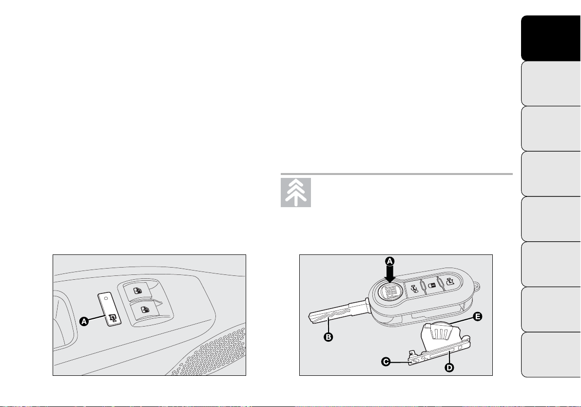
Unlocking the load compartment from inside the
vehicle (Cargo versions)
Pressing button A-fig. 5 unlocks the loading area (rear
swing doors/boot and sliding side doors) from inside the
vehicle. If the LED is on, the load compartment is locked.
Replacing the battery of the key with remote
control fig. 6
To replace the battery, proceed as follows:
❒
press button A and bring the metal insert B to the open
position;
❒
turn the screw C to :using a fine screwdriver;
❒
take out the battery case D and replace the battery E,
respecting its polarity;
❒
refit the battery case D inside the key and lock it by
turning the screw C to Á.
Used batteries are harmful to the environment. You can dispose of them either in the
correct containers as specified by law or
by taking them to the Fiat Service Network, who
will deal with their disposal.
KNOW
YOUR
VEHICLE
SAFETY
STARTING
AND
DRIVING
WARNING
LIGHTS AND
MESSAGES
IN AN
EMERGENCY
SERVICING
AND
MAINTENANCE
fig. 5
F0V0022m
fig. 6
TECHNICAL
SPECIFICATIONS
INDEX
F0V0005m
7
Page 9
KNOW
VEHICLE
SAFETY
Requesting additional remote controls
The system acknowledges up to 8 remote controls. Should
YOUR
a new remote control be necessary, contact the Fiat Service Network and be ready to present the CODE card, a
personal identity document and the vehicle ownership
documents.
WARNING
If the remote control battery is flat, the
system can only be turned on by inserting
the metal key in the door lock: in this case, the
device remains active for the rear doors only.
STARTING
DRIVING
WARNING
LIGHTS AND
MESSAGES
EMERGENCY
SERVICING
MAINTENANCE
TECHNICAL
SPECIFICATIONS
DEAD LOCK
AND
(for versions/markets where provided)
This safety device prevents the opening of the doors from
inside the passenger compartment if there has been a break
in attempt (e.g. a window has been broken).
The dead lock device therefore offers the best possible
protection against break in attempts. We recommend engaging it whenever the vehicle is parked and left unat-
IN AN
tended.
AND
side the vehicle. Before engaging the system please
therefore check that there is no one left on board.
INDEX
8
WARNING
Once the dead lock system is engaged it
is impossible to open the doors from in-
Switching the device on
The system is automatically enabled on all the doors by
Á
pressing button
The direction indicators flash twice to let you know that
the device is active.
If one or more of the doors is not perfectly shut, the dead
lock device will not be activated, thus preventing a person getting into the vehicle through the open door and,
on shutting, it, remaining stuck inside the passenger compartment.
Switching the device off
The system is disabled automatically on every door when:
❒
unlocking the doors;
❒
turning the ignition key to MAR.
twice on the key with remote control.
Page 10

STARTING DEVICE
The key can be turned to three different positions fig. 7:
❒
STOP: engine off, key can be extracted, steering locked.
Some electrical devices (e.g. radio, central door locking system, etc.) can operate.
❒
MAR: driving position. All electrical devices can operate.
❒
AVV: engine starting (temporary position).
The starting device is fitted with an electronic safety system that, should the engine fail to start, forces you to turn
the ignition key back to STOP before repeating the starting operation.
STEERING LOCK
Engagement
When at STOP, remove the key and turn the steering
wheel until it locks.
Disengagement
Move the steering wheel slightly as you turn the ignition
key to MAR.
WARNING
If the starting device has been tampered
with (e.g. an attempted theft), have it
checked over by the Fiat Service Network as soon
as possible.
KNOW
YOUR
VEHICLE
SAFETY
STARTING
AND
DRIVING
WARNING
LIGHTS AND
MESSAGES
IN AN
EMERGENCY
SERVICING
AND
MAINTENANCE
fig. 7
F0V0006m
TECHNICAL
SPECIFICATIONS
INDEX
9
Page 11
KNOW
YOUR
VEHICLE
accidentally activating the controls. Remember
to engage the handbrake. Engage first gear if the
SAFETY
vehicle is parked uphill or reverse gear if the vehicle is parked downhill. Never leave children unattended in the vehicle.
STARTING
AND
DRIVING
WARNING
LIGHTS AND
MESSAGES
IN AN
EMERGENCY
SERVICING
AND
MAINTENANCE
TECHNICAL
SPECIFICATIONS
WARNING
When getting out of the vehicle, always
remove the key to prevent someone from
WARNING
Never extract the key while the vehicle is
moving. The steering wheel should lock automatically as soon as it is turned. This is always
the case, even when the vehicle is being towed.
WARNING
It is absolutely forbidden to carry out any
aftersales operation involving steering system or steering column modifications (e.g. installing
an anti-theft device) that could badly affect performance and safety, invalidate the warranty and
also result in the vehicle failing to comply with regulations.
INDEX
10
Page 12
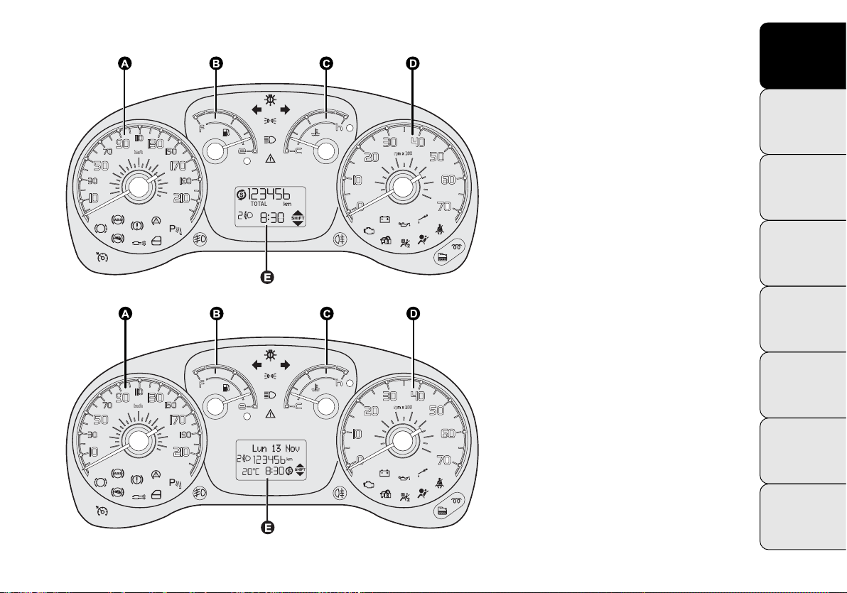
INSTRUMENT PANEL
fig. 9
F0V0001m
Versions with digital display
A Speedometer
B Fuel level gauge with reserve warn-
ing light
C Engine coolant temperature gauge
with overheating warning light
D Rev counter
E Digital display
Versions with multifunction
display
A Speedometer
B Fuel level gauge with reserve warn-
ing light
C Engine coolant temperature gauge
with overheating warning light
D Rev counter
E Multifunction display
KNOW
YOUR
VEHICLE
SAFETY
STARTING
AND
DRIVING
WARNING
LIGHTS AND
MESSAGES
IN AN
EMERGENCY
SERVICING
AND
MAINTENANCE
TECHNICAL
SPECIFICATIONS
fig. 10
INDEX
F0V0002m
11
Page 13
KNOW
VEHICLE
SAFETY
INSTRUMENTS
YOUR
Instrument background colour and type may vary according to the version.
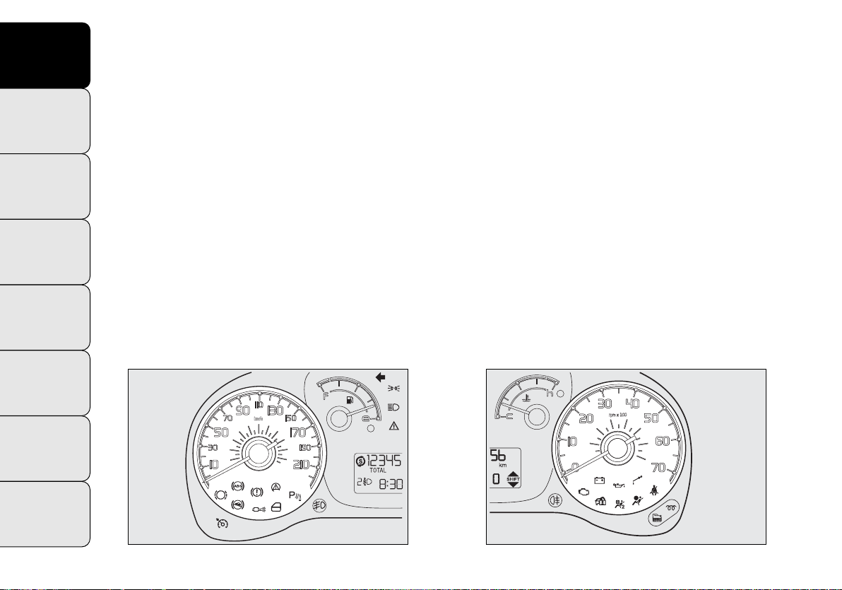
SPEEDOMETER fig. 11
This shows the speed at which the vehicle is travelling.
STARTING
AND
DRIVING
WARNING
LIGHTS AND
MESSAGES
IN AN
EMERGENCY
SERVICING
AND
MAINTENANCE
REV COUNTER fig. 12
The rev counter shows the number of engine rpm.
WARNING The electronic injection control system gradually shuts off the flow of fuel when the engine is overrevving, resulting in a gradual loss of engine power.
When the engine is idling, the rev counter may indicate
a gradual or sudden increase in the rate.
This is normal and does not indicate a fault. It may be
caused, for example, by the operation of the climate control system or fan. In such cases, a slight increase in engine idle speed helps to sustain the battery charge.
TECHNICAL
SPECIFICATIONS
INDEX
12
fig. 11
F0V0007m
fig. 12
F0V0008m
Page 14
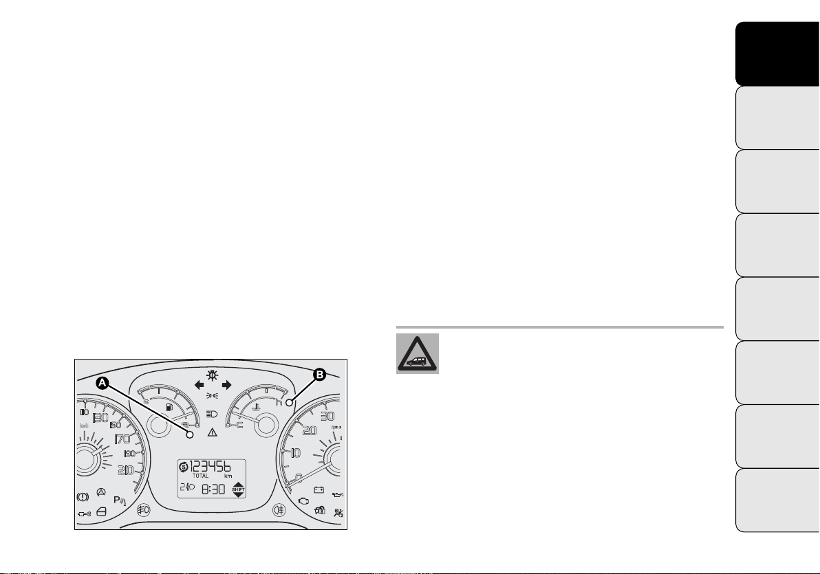
FUEL LEVEL GAUGE fig. 13
This shows the amount of fuel left in the tank.
E tank empty.
F tank full (see “Refuelling”).
Warning light A comes on to indicate that approximately
8-10 litres of fuel are left in the tank.
Do not travel with the fuel tank almost empty: the gaps
in fuel delivery could damage the catalytic converter.
WARNING The needle will point to E and warning light
A will flash to indicate a fault in the system. If this is the
case, go to the Fiat Service Network to have the system
checked.
ENGINE COOLANT TEMPERATURE
GAUGE fig. 13
This shows the temperature of the engine coolant and
starts working when the fluid temperature exceeds approx. 50 °C.
In normal usage, the needle should hover around the middle of the scale.
C Low engine coolant temperature.
H High engine coolant temperature.
Warning light B may light up (and a message on the multifunction display may appear on certain versions) to indicate that the coolant temperature is too high; in this case,
stop the engine and contact the Fiat Service Network.
If the needle enters the red zone, switch off
the engine immediately and contact the
Fiat Service Network.
KNOW
YOUR
VEHICLE
SAFETY
STARTING
AND
DRIVING
WARNING
LIGHTS AND
MESSAGES
IN AN
EMERGENCY
SERVICING
AND
MAINTENANCE
fig. 13
TECHNICAL
SPECIFICATIONS
INDEX
F0V0009m
13
Page 15
KNOW
DIGITAL DISPLAY
YOUR
VEHICLE
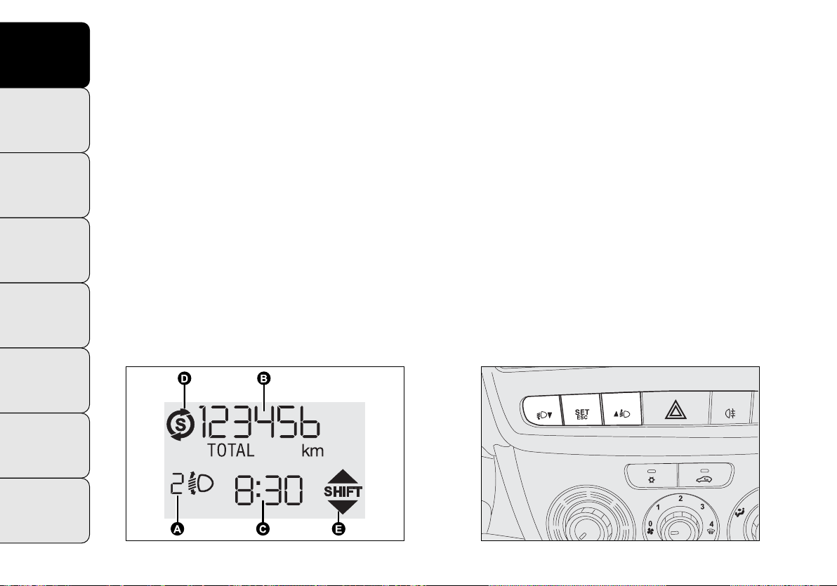
STANDARD SCREEN fig. 14
The standard screen shows the following information:
SAFETY
A Headlamp alignment position (only with dipped head-
lamps on).
B Milometer (distance covered in km or miles).
STARTING
DRIVING
C Time (always displayed, even with the key extracted
AND
and the front doors closed).
D Start&Stop indicator (for versions/markets where pro-
WARNING
LIGHTS AND
MESSAGES
vided).
E Gear Shift Indicator (for versions/markets where pro-
vided).
IN AN
EMERGENCY
SERVICING
AND
MAINTENANCE
N.B. With the ignition key removed, when a door is
opened, the display lights up and shows the time and total distance covered (in km or miles) for a few seconds.
CONTROL BUTTONS fig. 15
▲ To scroll up the screen and the menu options or in-
crease the displayed value.
SET ESC Press to access the menu and/or go to the
next screen or confirm your choice.
Hold down to go back to the standard screen.
▼ To scroll down the screen and the menu options or
decrease the displayed value.
TECHNICAL
SPECIFICATIONS
INDEX
14
fig. 14
F0V0011m
fig. 15
F0V0012m
Page 16

N.B. Buttons ▲ and ▼ activate different functions in the
following situations:
– within the menu, they scroll up and down;
– during setting operations they increase or decrease the
value.
SETUP MENU
The menu comprises a series of functions arranged in a circle which can be selected through buttons ▲ and ▼ to
access the settings described below.
The setup menu can be activated by pressing the SET ESC
button.
By pressing buttons ▲ and ▼ you can scroll through the
setup menu options.
Management modes differ from each other according to
the option selected.
The menu comprises the following functions:
– ILLU
– SPEED
– HOUR
– UNIT
– BUZZ
– BAG P
– DRL
Selecting a menu option
– press the SET ESC button to select the menu option
to set;
– press buttons ▲ and ▼ to select the new setting;
– press the SET ESC button to memorize the new setting and go back to the previous menu option.
Selecting “Set clock”
– press the SET ESC button to select the first value to
change (hours);
– press buttons ▲ and ▼ to select the new setting;
– press the SET ESC button to memorize the new setting and go to the next value (minutes);
– after setting the value with the same procedure, you go
back to the previous menu item.
KNOW
YOUR
VEHICLE
SAFETY
STARTING
AND
DRIVING
WARNING
LIGHTS AND
MESSAGES
IN AN
EMERGENCY
SERVICING
AND
MAINTENANCE
TECHNICAL
SPECIFICATIONS
INDEX
15
Page 17

KNOW
VEHICLE
SAFETY
STARTING
DRIVING
WARNING
LIGHTS AND
MESSAGES
EMERGENCY
SERVICING
MAINTENANCE
Hold down the SET ESC button
– to quit the setup menu if you are in the menu;
YOUR
– to quit to the menu if you are setting an option;
– to save only the settings already memorized (confirmed
by pressing the SET ESC button).
The setup menu page is timed. Only the changes already
memorized by pressing the SET ESC button are saved
when you come out of the menu.
AND
Adjusting the vehicle interior lighting
(ILLU)
This function is available, with the dipped headlamps on
and at night, to adjust the brightness of the instrument
panel, buttons, radio display and automatic climate control display.
IN AN
During the daytime, and with the dipped headlamps on,
the instrument panel, buttons and radio and automatic
climate control displays are set to maximum brightness.
AND
Proceed as follows to adjust the brightness:
– press the SET ESC button: the display will show ILLU;
– press button ▲ or ▼ to adjust the brightness level;
– press the SET ESC button to go back to the menu screen
or hold the button down to go back to the standard screen
without saving.
Setting the speed limit (SPEEd)
This function is used to set a speed limit (km/h or mph);
the driver is alerted when this limit is exceeded (see
“Warning lights and messages”).
To set the desired speed limit, proceed as follows:
– press SET ESC: the word SPEEd and the previously set
unit (km/h or mph) will appear on the display;
– press button ▲ or ▼ to select speed limit activation
(On) or deactivation (Off);
– when the function is activated (On), press buttons
▲ or ▼ to select the speed limit and press SET ESC to
confirm.
TECHNICAL
SPECIFICATIONS
INDEX
16
Page 18

N.B. You can select a speed between 30 and 200 km/h
or 20 and 125 mph, depending on the chosen unit (see
“Setting the unit of measurement (Unit)”). The setting will
increase/decrease by five units each time button ▲/▼ is
pressed. Hold down button ▲/▼ to increase/decrease
the setting rapidly. Complete the setting with single presses of the button when you approach the required setting.
– press the SET ESC button to go back to the menu screen
or hold the button down to go back to the standard screen
without saving.
To cancel the setting, proceed as follows:
– press the SET ESC button: ON flashes in the display;
– press button ▼: OFF flashes in the display;
– press the SET ESC button to go back to the menu screen
or hold the button down to go back to the standard screen
without saving.
Setting the clock (Hour)
With this function, it is possible to set the time.
To do so, proceed as follows:
– press SET ESC: the hours flash in the display;
– press button ▲ or ▼ to adjust the value;
– press SET ESC: the minutes flash in the display;
– press ▲ or ▼ to adjust the value;
– press the SET ESC button to go back to the menu screen
or hold the button down to go back to the standard screen
without saving.
Setting the unit of measurement (Unit)
With this function, it is possible to set the distance unit.
To do so, proceed as follows:
– press SET ESC: the display shows the word Unit and
the previously set unit of measurement (km or mi);
– press button ▲ or ▼ to select the required unit of mea-
surement.
– press the SET ESC button to go back to the menu screen
or hold the button down to go back to the standard screen
without saving.
KNOW
YOUR
VEHICLE
SAFETY
STARTING
AND
DRIVING
WARNING
LIGHTS AND
MESSAGES
IN AN
EMERGENCY
SERVICING
AND
MAINTENANCE
TECHNICAL
SPECIFICATIONS
INDEX
17
Page 19

KNOW
VEHICLE
SAFETY
STARTING
DRIVING
WARNING
LIGHTS AND
MESSAGES
EMERGENCY
SERVICING
MAINTENANCE
TECHNICAL
SPECIFICATIONS
Adjusting the buzzer volume (BUZZ)
This function is used to adjust the volume of the buzzer
YOUR
that sounds in the event of failure/warning indications and
when the SET ESC, ▲ and ▼ buttons are pressed.
To set the desired volume, proceed as follows:
– press SET ESC: the display shows the word bUZZ;
– press ▲ or ▼ to select the required volume (adjustable
over eight levels).
AND
– press the SET ESC button to go back to the menu screen
or hold the button down to go back to the standard screen
without saving.
Passenger front and side airbag
activation/deactivation (BAG P)
(for versions/markets where provided)
IN AN
This function is used to activate/deactivate the front and
side passenger airbags (for versions/markets where provided).
Proceed as follows:
AND
❒
press SET ESC and, after the message BAG P OFF (to
deactivate) or BAG P On (to activate) is displayed by
pressing buttons ▲ or ▼, press SET ESC again;
❒
the confirmation request message is displayed;
❒
press ▲ or ▼ to select YES (confirming activation/deactivation) or no (to cancel);
❒
INDEX
press SET ESC to confirm setting and go back to the
menu screen or hold the button down to go back to
the standard screen without saving.
Daytime Running Lights (DRL)
This function allows you to activate/deactivate the daytime running lights.
Proceed as follows to switch this function on or off:
– press the SET ESC button: the display shows DRL;
– press button ▲ or ▼ to activate (On) or deactivate
(Off) the daytime running lights;
– press the SET ESC button to return to the submenu
screen or hold the button down to return to the main
menu screen without saving;
18
Page 20
MULTIFUNCTION DISPLAY
(for versions/markets where provided)
The vehicle may be equipped with a multifunction display
that gives the driver useful information depending on the
previous settings.
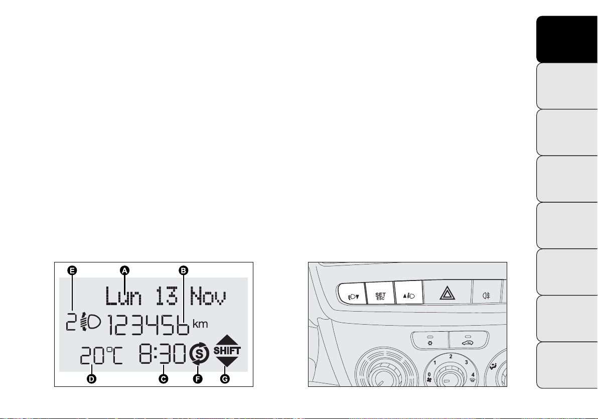
STANDARD SCREEN fig. 16
The standard screen shows the following information:
A Date.
B Milometer (distance covered in km or miles).
C Time (always displayed, even with the key extracted
and the front doors closed);
D Outside temperature.
E Headlamp alignment position (only with dipped head-
lamps on).
F Start&Stop indicator (for versions/markets where pro-
vided)
G Gear Shift Indicator (for versions/markets where pro-
vided)
N.B. When one of the front doors is opened, the display
turns on and shows the time and distance covered (in km
or mi) for a few seconds.
CONTROL BUTTONS fig. 17
▲ To scroll up the screen and the menu options or in-
crease the displayed value.
SET ESC Press to access the menu and/or go to the
next screen or confirm your choice.
Hold down to go back to the standard screen.
▼ To scroll down the screen and the menu options or
decrease the displayed value.
KNOW
YOUR
VEHICLE
SAFETY
STARTING
AND
DRIVING
WARNING
LIGHTS AND
MESSAGES
IN AN
EMERGENCY
SERVICING
AND
MAINTENANCE
fig. 16
F0V0038m
fig. 17
TECHNICAL
SPECIFICATIONS
INDEX
F0V0012m
19
Page 21

KNOW
VEHICLE
SAFETY
STARTING
DRIVING
WARNING
LIGHTS AND
MESSAGES
EMERGENCY
SERVICING
MAINTENANCE
TECHNICAL
SPECIFICATIONS
N.B. Buttons ▲ and ▼ activate different functions in the
following situations:
YOUR
Adjusting the vehicle’s interior lighting
– on the standard screen, they adjust the brightness of
the instrument panel and the radio.
Setup menu
– within the menu, they scroll up and down;
AND
– during setting operations they increase or decrease the
value.
IN AN
AND
INDEX
SETUP MENU
The menu comprises a series of functions arranged in a circle which can be selected through buttons ▲ and ▼ to
access the settings described below. A submenu is provided for some items (Clock and Unit of measurement).
The setup menu can be activated by pressing SET ESC.
Pressing buttons ▲ or ▼ scrolls through the setup menu
options. Management modes differ from each other according to the option selected. The menu comprises the
following functions:
– LIGHTING
– SPEED BEEP
– TRIP B DATA
– SET TIME
– SET DATE
– RADIO INFO (if present)
– AUTOCLOSE
– UNIT OF MEASUREMENT
– LANGUAGE
– WARNING VOLUME
– BUTTON VOLUME
– SEAT BELT BUZZER
(only if previously disabled)
– SERVICE
20
Page 22

– PASSENGER AIRBAG
– DAYTIME RUNNING LIGHTS
– EXIT MENU
Selecting an option from the main menu without a submenu:
– press SET ESC to select the main menu option you wish
to set;
– press ▲ or ▼ to select the new setting;
– press the SET ESC button to memorize the new setting and go back to the previous main menu option.
Selecting an option from the main menu with a submenu:
– press the SET ESC button to display the first submenu
option;
– press ▲ or ▼ to scroll through all the submenu options;
– press the SET ESC button to select the displayed submenu option and open the relevant setup menu;
– press ▲ or ▼ to select the new setting for this submenu option;
– press the SET ESC button to memorize the new setting and go back to the previous submenu option.
MENU FUNCTIONS
Adjusting the vehicle interior lighting
This function is available, with the dipped headlamps on
and at night, to adjust the brightness of the instrument
panel, buttons, radio display and automatic climate control display.
During the daytime, and with the dipped headlamps on,
the instrument panel, buttons and radio and automatic
climate control displays are set to maximum brightness.
Proceed as follows to adjust the brightness:
– press SET ESC: the previously set brightness level flashes in the display;
– press button ▲ or ▼ to adjust the brightness level;
– press the SET ESC button to go back to the menu screen
or hold the button down to go back to the standard screen
without saving.
Speed beep (Speed limit)
This function makes it possible to set the vehicle speed
limit (km/h or mph). When this limit is exceeded the driver is immediately alerted (see “Warning lights and messages” section).
To set the desired speed limit, proceed as follows:
– press the SET ESC button: the display shows the words
Speed Beep;
– press button ▲ or ▼ to select speed limit activation
(On) or deactivation (Off);
KNOW
YOUR
VEHICLE
SAFETY
STARTING
AND
DRIVING
WARNING
LIGHTS AND
MESSAGES
IN AN
EMERGENCY
SERVICING
AND
MAINTENANCE
TECHNICAL
SPECIFICATIONS
INDEX
21
Page 23

KNOW
VEHICLE
SAFETY
STARTING
DRIVING
WARNING
LIGHTS AND
MESSAGES
EMERGENCY
SERVICING
MAINTENANCE
TECHNICAL
SPECIFICATIONS
– if the function is on, press ▲ or ▼ to select the required speed limit and then press SET ESC to confirm;
YOUR
N.B. The speed may be set anywhere between 30 and
200 km/h or 20 and 125 mph, depending on the previously chosen unit (see “Setting the unit of measurement
(Unit)”). The setting will increase/decrease by five units
each time button ▲/▼ is pressed. Hold down button ▲/▼
to increase/decrease the setting rapidly. Complete the
setting with single presses of the button when you approach the required setting.
AND
– press the SET ESC button to go back to the menu screen
or hold the button down to go back to the standard screen
without saving.
To cancel the setting, proceed as follows:
– press the SET ESC button: ON flashes in the display;
– press button ▼: OFF flashes in the display;
IN AN
– press the SET ESC button to go back to the menu screen
or hold the button down to go back to the standard screen
without saving.
AND
Trip B data (Activating Trip B)
This function may be used to activate (On) or deactivate
(Off) the Trip B display (partial trip).
For more information see the „Trip computer” section.
For activation/deactivation, proceed as follows:
– press the SET ESC button again: the display flashes On
INDEX
or Off depending on what was previously set;
– press ▲ or ▼ to select;
– press the SET ESC button to go back to the menu screen
or hold the button down to go back to the standard screen
without saving.
Setting the time (Clock)
This function allows you to set the clock through two submenus: “Time” and “Mode”.
To carry out the adjustment, proceed as follows:
– press SET ESC: the display shows the two submenus
“Time” and “Mode”;
– press ▲ or ▼ to move between the two submenus;
– once you have selected a submenu, press SET ESC;
22
Page 24

– when you select “Time”, pressing SET ESC makes the
hours flash on the display;
– press ▲ or ▼ to adjust the value;
– press SET ESC: the minutes flash in the display;
– press ▲ or ▼ to adjust the value.
N.B. The setting will increase or decrease by one unit each
time ▲ or ▼ is pressed. Hold the button down to increase/decrease the setting rapidly. Complete the setting
with single presses of the button when you approach the
required setting.
– when you select “Mode”, pressing SET ESC makes the
mode flash on the display;
– press ▲ or ▼ to select 24h or 12h.
When you have made the required adjustments, press
SET ESC to go back to the submenu screen or hold the
button down to go back to the main menu screen without saving.
– hold down SET ESC again to go back to the standard
screen or main menu, depending on which point in the
menu you have reached.
Set date (Setting the date)
Using this function it is possible to change the date (day
– month – year).
To update, proceed as follows:
– press SET ESC: the year flashes on the display;
– press ▲ or ▼ to adjust the value;
– press SET ESC: the month flashes in the display;
– press ▲ or ▼ to adjust the value;
– press SET ESC: the day flashes in the display;
– press ▲ or ▼ to adjust the value.
N.B. The setting will increase or decrease by one unit each
time ▲ or ▼ is pressed. Hold the button down to increase/decrease the setting rapidly. Complete the setting
with single presses of the button when you approach the
required setting.
– press the SET ESC button to go back to the menu screen
or hold the button down to go back to the standard screen
without saving.
KNOW
YOUR
VEHICLE
SAFETY
STARTING
AND
DRIVING
WARNING
LIGHTS AND
MESSAGES
IN AN
EMERGENCY
SERVICING
AND
MAINTENANCE
TECHNICAL
SPECIFICATIONS
INDEX
23
Page 25

KNOW
VEHICLE
SAFETY
STARTING
DRIVING
WARNING
LIGHTS AND
MESSAGES
EMERGENCY
SERVICING
MAINTENANCE
TECHNICAL
SPECIFICATIONS
Radio info (Display audio information)
With this function the display shows information relevant
YOUR
to the radio.
– Radio: selected radio station frequency or RDS message, automatic tuning activation or AutoSTore;
– Audio CD, CD MP3: track number;
To show the radio information in the display (On) or clear
it (Off), proceed as follows:
AND
– press the SET ESC button: the display flashes On or Off
depending on the previous setting;
– press ▲ or ▼ to select;
– press the SET ESC button to go back to the menu screen
or hold the button down to go back to the standard screen
without saving.
IN AN
Autoclose (Automatic central locking with the
vehicle in motion)
(for versions/markets where provided)
When activated (On), this function automatically locks
AND
the doors when the car speed exceeds 20 km/h.
Proceed as follows to switch this function on or off:
– press the SET ESC button: the display shows a submenu;
– press the SET ESC button again: the display flashes On
or Off depending on the previous setting;
– press ▲ or ▼ to select;
– press the SET ESC button to return to the submenu
screen or hold the button down to return to the main
menu screen without saving;
– hold down SET ESC again to go back to the standard
screen or main menu, depending on which point in the
menu you have reached.
Unit of measurement (Setting the unit
of measurement)
With this function it is possible to set the measurement
units through three submenus: “Distance”, “Consumption” and “Temperature”.
To set the desired measurement unit, proceed as follows:
– press SET ESC to display the three submenus;
– press ▲ or ▼ to move between the three submenus;
– once you have selected a submenu, press SET ESC;
– when you select “Distance”, pressing SET ESC makes
km or mi appear in the display (depending on the previous setting);
INDEX
24
Page 26

– press ▲ or ▼ to choose;
– when you select “Consumption”, pressing SET ESC
makes km/l, l/100km or mpg appear on the display depending on the previous setting;
If the set distance unit is “km”, you can set the fuel consumption unit to km/l or l/100km depending on the
amount of fuel consumed.
If the distance unit is set to mi, fuel consumption is displayed in mpg.
– press ▲ or ▼ to select;
– when you select “Temperature”, pressing SET ESC
makes °C or °F appear on the display depending on the
previous setting;
– press ▲ or ▼ to select;
When you have made the required adjustments, briefly
press MENU ESC to go back to the submenu screen or
hold the button down to go back to the main menu screen
without saving.
– hold down SET ESC again to go back to the standard
screen or main menu, depending on which point in the
menu you have reached.
Language (Selecting the language)
Display messages can be shown in different languages: Italian, English, German, Portuguese, Spanish, French, Dutch,
Polish and Turkish.
To set the required language, proceed as follows:
– press SET ESC: the previously set language flashes in
the display;
– press ▲ or ▼ to select;
– press the SET ESC button to go back to the menu screen
or hold the button down to go back to the standard screen
without saving.
Warning volume (Adjusting the failure/warning
buzzer volume)
This function allows the volume of the buzzer which accompanies the display of failures/warnings to be adjusted
(over 8 levels).
To set the desired volume, proceed as follows:
– press SET ESC: the previously set volume level flashes
in the display;
– press ▲ or ▼ to adjust the value;
– press the SET ESC button to go back to the menu screen
or hold the button down to go back to the standard screen
without saving.
KNOW
YOUR
VEHICLE
SAFETY
STARTING
AND
DRIVING
WARNING
LIGHTS AND
MESSAGES
IN AN
EMERGENCY
SERVICING
AND
MAINTENANCE
TECHNICAL
SPECIFICATIONS
INDEX
25
Page 27

KNOW
VEHICLE
SAFETY
STARTING
DRIVING
WARNING
LIGHTS AND
MESSAGES
EMERGENCY
SERVICING
MAINTENANCE
TECHNICAL
SPECIFICATIONS
Button volume (Adjusting the button volume)
This function allows you to adjust (over 8 levels) the vol-
YOUR
ume of the buzzer that can be heard when the SET ESC,
▲ and ▼ buttons are pressed.
To set the desired volume, proceed as follows:
– press SET ESC: the previously set volume level flashes
in the display;
– press ▲ or ▼ to adjust the value;
AND
– press the SET ESC button to go back to the menu screen
or hold the button down to go back to the standard screen
without saving.
Seat belt buzzer
(Reactivating buzzer for SBR indication)
This function can only be displayed after the Fiat Service
IN AN
Network has deactivated the SBR system (see “SBR system” in the “Safety” section).
AND
Service (Programmed maintenance)
Through this function it is possible to display information
related to regular maintenance intervals.
This information can be consulted as follows:
– press SET ESC: the service intervals appear in the display in km or mi, depending on the previous setting
(see “Unit of distance” paragraph);
– press the SET ESC button to return to the menu screen
or hold the button down to return to the standard screen.
N.B. The „Scheduled Servicing Plan” provides for the vehicle to be serviced every 30,000 km/35,000 km (depending
on the version) (or the equivalent in miles). This is automatically displayed, when the ignition key is at MAR, from
2,000 km (or the equivalent in miles) and reappears every
200 km (or the equivalent in miles). Below 200 km the
reminders become more frequent. The indication will appear in kilometres or miles depending on the measurement unit settings. When the next scheduled service is
approaching, the message „Service” will appear on the
display, followed by the number of kilometres or miles
left, when the key is turned to MAR. Go to the Fiat Service Network, where the „Planned Maintenance Programme” operations will be performed and the message
will be reset.
INDEX
26
Page 28

Activating/deactivating passenger front and side
airbags
(for versions/markets where provided)
This function is used to activate/deactivate the front and
side passenger airbags (for versions/markets where provided).
Proceed as follows:
– press SET ESC and, after the message Bag pass: Off (to
deactivate) or Bag pass On (to activate) is displayed by
pressing buttons ▲ or ▼, press SET ESC again;
– the confirmation request message appears in the display;
– press ▲ or ▼ to select Yes (confirming activation/deactivation) or No (to cancel);
– press SET ESC to confirm the setting and go back to
the menu screen or hold the button down to go back to
the standard screen without saving.
Daytime Running Lights (DRL)
This function allows you to activate/deactivate the daytime running lights.
Proceed as follows to switch this function on or off:
– press the SET ESC button to display a submenu;
– press the SET ESC button again: the display flashes On
or Off depending on what was previously set;
– press ▲ or ▼ to select;
– press the SET ESC button to return to the submenu
screen or hold the button down to return to the main
menu screen without saving;
– hold down SET ESC again to go back to the standard
screen or main menu, depending on which point in the
menu you have reached.
Exit menu
This function closes the settings listed on the menu screen.
Press SET ESC to go back to the standard screen without saving.
Press ▼ to return to the first menu option (Speed beep).
KNOW
YOUR
VEHICLE
SAFETY
STARTING
AND
DRIVING
WARNING
LIGHTS AND
MESSAGES
IN AN
EMERGENCY
SERVICING
AND
MAINTENANCE
TECHNICAL
SPECIFICATIONS
INDEX
27
Page 29

KNOW
VEHICLE
SAFETY
STARTING
DRIVING
WARNING
LIGHTS AND
MESSAGES
EMERGENCY
SERVICING
MAINTENANCE
TECHNICAL
SPECIFICATIONS
TRIP COMPUTER
General information
YOUR
The Trip computer is used to display information on vehicle operation when the ignition key is turned to MAR.
This function allows you to define two separate trips, called
“Trip A” and “Trip B”, for monitoring the vehicle’s „complete mission” (journey) in a reciprocally independent manner. Both functions can be reset (reset – start of a new
journey).
AND
“Trip A” is used to display the figures relating to:
– Range
– Distance travelled
– Average consumption
– Instant consumption
– Average speed
IN AN
– Travel time (driving time).
“Trip B”, available on multifunction display only, is used
to display the figures relating to:
– Distance travelled B
AND
– Average consumption B
– Average speed B
– Travel time B (driving time).
N.B. “Trip B” may be disabled (see “Activating Trip B”).
“Range” and “Instant consumption” parameters cannot
be reset.
INDEX
Values displayed
Range
Shows the approximate distance the vehicle can travel
with the amount of fuel left in the tank. The display will
show the reading “----” when the following events take
place:
– range is lower than 50 km (or 30 mi)
– vehicle is left parked with the engine running for a long
time.
WARNING The range can be affected by several factors:
driving style (see “Driving style” in the “Starting and driving” section), type of route (motorway, towns and cities,
mountain roads, etc.), conditions of use (load, tyre pressures, etc.). Trip planning must therefore take the above
into account.
Distance travelled
Shows the distance covered since the start of the new
journey.
Average consumption
Shows the approximate average fuel consumption since
the start of the new journey.
Current consumption
Shows the constantly updated fuel consumption. The reading “----” appears on the display if the vehicle is parked
with the engine running.
Average speed
Shows the average speed of the vehicle by using the overall time elapsed since the start of a new journey.
28
Page 30
Journey time
Shows the time elapsed since the start of a new journey.
WARNING If information is not available, the reading
“----” appears instead of the Trip computer values. Counting the different values will resume regularly when normal operation condition is restored. This will not reset
any of the values displayed before the failure or start a new
journey.
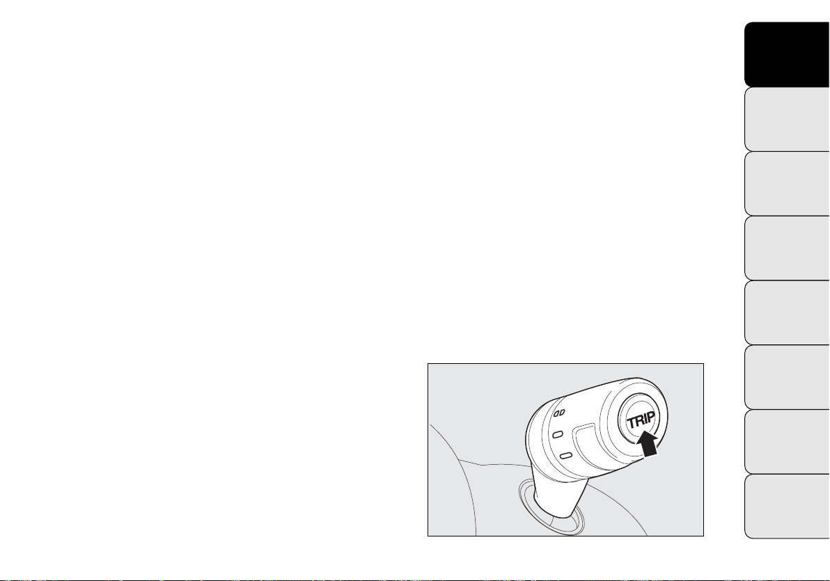
TRIP control button fig. 18
The TRIP button, located on the top of the right steering
column lever, is used (with ignition key at MAR) to display these values and reset them to start a new journey:
– press briefly to display the different values;
– hold down to reset and then start a new journey.
New journey
The new journey begins after:
– “manual” resetting by the user, by pressing the relevant
button;
– “automatic” resetting, when the distance travelled reaches 99999.9 km or 9999.9 km (depending on the type of
display) or when the travel time reaches 99.59 (99 hours
and 59 minutes) or 999.59 (999 hours and 59 minutes)
depending on the type of display fitted;
– disconnection/reconnection of the battery.
WARNING The reset operation when “Trip A” details
are being displayed only resets the information associated with this function.
WARNING The reset operation when “Trip B” details
are being displayed only resets the information associated with this function.
Start trip procedure
With the ignition key at MAR, reset by pressing the TRIP
button and holding it down for more than two seconds.
Exit Trip
To quit the Trip function, hold down SET ESC for more
than two seconds.
KNOW
YOUR
VEHICLE
SAFETY
STARTING
AND
DRIVING
WARNING
LIGHTS AND
MESSAGES
IN AN
EMERGENCY
SERVICING
AND
MAINTENANCE
TECHNICAL
SPECIFICATIONS
INDEX
fig. 18
F0V0010m
29
Page 31

KNOW
F
E
A
B
C
D
YOUR
VEHICLE
SAFETY
STARTING
AND
DRIVING
WARNING
LIGHTS AND
MESSAGES
IN AN
EMERGENCY
SERVICING
AND
MAINTENANCE
TECHNICAL
SPECIFICATIONS
INDEX
SEATS
DRIVER’S SEAT
(for Cargo versions where provided)
WARNING
All adjustments must be made with the vehicle stationary.
Longitudinal adjustment
Lift the lever A-Fig.19 and push the seat forwards or
backwards: in the driving position your arms should be
slightly bent and your hands should rest on the rim of
the steering wheel.
WARNING
After releasing the adjustment lever, always
check that the seat is locked into place by
trying to move it back and forth. If it is not locked,
the seat may move unexpectedly and make you lose
control of the vehicle.
Reclining backrest adjustment
Lift lever E-fig. 19 and, slightly detaching the back from
the backrest, accompany the movement of the backrest
until it is in the desired position.
Lumbar support adjustment fig. 19
(for versions/markets where available)
The lumbar support adjustment ensures better back sup-
port. To adjust, turn knob F.
Heated driver’s seat fig. 19
To switch on/off, press button B.
The LED in the button comes on to indicate activation.
Height adjustment
Move lever C-fig. 19 upwards to raise the front section
of the seat and lever D upwards to raise the rear section
of the seat. To lower the seat, move the levers downwards.
IMPORTANT The seat is raised when no one is on it; the
seat is lowered when sitting in the driver’s seat.
30
fig. 19
F0V0210m
Page 32

DRIVER’S SEAT fig. 20
(for Doblò/Doblò Combi/Cargo versions, where
provided)
WARNING
All adjustments must be made with the vehicle stationary.
Lengthwise adjustment
Lift lever A and push the seat forwards or backwards: in
the driving position your arms should rest on the rim of
the steering wheel.
WARNING
After releasing the adjustment lever, al-
ways check that the seat is locked into
place by trying to move it back and forth. If it is
not locked, the seat may move unexpectedly and
make you lose control of the vehicle.
Driver’s seat height adjustment
(for versions/markets where provided)
Operate lever C to lift or lower the rear part of the cushion to achieve the most comfortable driving position.
WARNING Adjustment must only be carried out when
seated in the relevant seat.
KNOW
YOUR
VEHICLE
SAFETY
STARTING
AND
DRIVING
WARNING
LIGHTS AND
MESSAGES
IN AN
EMERGENCY
SERVICING
AND
MAINTENANCE
Backrest inclination adjustment
Turn knob B.
fig. 20
TECHNICAL
SPECIFICATIONS
INDEX
F0V0013m
31
Page 33

KNOW
VEHICLE
Driver’s seat lumbar support adjustment
(for versions/markets where provided)
YOUR
Turn knob D-fig. 20 to adjust the backrest support.
Seat heating
SAFETY
(for versions/markets where provided)
With the key turned to MAR, press button A-fig. 21 to
switch the function on/off.
STARTING
DRIVING
When the function is enabled, the LED on the button
AND
turns on.
WARNING
LIGHTS AND
MESSAGES
IN AN
EMERGENCY
SERVICING
AND
MAINTENANCE
FOLDAWAY PASSENGER SEAT
(for versions/markets where provided)
The passenger seat can be folded away on some Cargo
versions.
TECHNICAL
SPECIFICATIONS
INDEX
32
fig. 21
F0V0208m
fig. 22
F0V0142m
Page 34

Seat folding
To fold the seat, proceed as follows:
❒
open the passenger side door;
❒
pull lever A-fig. 22 and fold the backrest forwards in
the direction indicated by the arrow;
❒
then push the backrest B-fig. 23 down: the seat is
now completely folded over on itself into the “table”
position;
❒
pull flap C-fig. 24 and push the backrest down further:
the seat is now completely folded away.
Repositioning the seat
To return the seat back to its normal position, proceed
as follows:
❒
grab flap A-fig. 25 and lift the backrest;
❒
pull on levers B-fig. 26 and lift the seat up further.
fig. 24
F0V0144m
KNOW
YOUR
VEHICLE
SAFETY
STARTING
AND
DRIVING
WARNING
LIGHTS AND
MESSAGES
IN AN
EMERGENCY
SERVICING
AND
MAINTENANCE
fig. 23
F0V0143m
fig. 25
TECHNICAL
SPECIFICATIONS
INDEX
F0V0145m
33
Page 35

KNOW
YOUR
VEHICLE
ing. When the vehicle is in motion, you are there-
fore advised to remove or secure any objects that
SAFETY
might interfere with the driver. If there is no par-
tition between the cab and the load compartment,
tall objects or packages may take up part of the
passenger area. Make sure that these items are
STARTING
DRIVING
well secured by using the available hooks and that
AND
they cannot interfere with the driver.
WARNING
LIGHTS AND
MESSAGES
ACCESS TO THE REAR SEATS
(Doblò and Doblò Combi versions)
To access the rear seats, open one of the sliding side doors
IN AN
EMERGENCY
(see “Doors” in this section).
SERVICING
AND
MAINTENANCE
WARNING
When the passenger seat is folded away,
the space created cannot be used for load-
SEAT THAT CAN BE FOLDED INTO TABLE
(Doblò and Doblò Combi versions, where provided)
On some versions the seat can be folded into a table position.
WARNING Only move the seat when there are no rear
passengers.
Seat folding
❒
Open the passenger side door;
❒
Pull lever A and fold the backrest forwards in the direction
indicated by the arrow;
❒
Then push the backrest B down: the seat is now completely folded over on itself into the “table” position;
Repositioning the seat:
❒
operate lever A and lift the backrest upwards.
TECHNICAL
SPECIFICATIONS
INDEX
34
fig. 26
F0V0146m
fig. 26b
F0V0201m
Page 36

3rdROW SEAT MOVEMENTS
B
A
Proceed as follows:
❒
fully lower the rear seat head restraints;
❒
move the seat belt to the side, making sure that it is
fully extended and not twisted;
❒
lift lever A-fig. 26c retaining the backrest and fold the
latter forwards. When you lift the lever, you will see
a red band;
❒
pull the tape B-fig. 26c behind the seat backrests and
fold the seats and the backrests forwards;
N.B. On the split seats, there are rubber bands on the lower
edge of the cushion so you can attach the folded seat to the 2
row rear seat head restraint rods.
nd
3rdROW SEAT REMOVAL
Proceed as follows:
❒
remove the rear seat head restraints;
❒
move the seat belt to the side, making sure that it is
fully extended and not twisted;
❒
lift lever A-fig. 26c retaining the backrest and fold the
latter forwards. When you lift the lever, you will see
a red band.
❒
pull the tape B-fig. 26c behind the seat backrests and
fold the seats and the backrests forwards.
❒
position the head restraint using the openings under
the cushion to insert the rods;
❒
push the lever as illustrated in fig. 26d;
❒
remove the seat from the attachments on the floor.
rd
3
ROW SEAT REPOSITIONING
Proceed as follows:
❒
attach the hooks to the floor fig. 26e;
❒
push the lever as illustrated in fig. 26d and pull it to
make sure that the seat is still correctly secured;
❒
withdraw the head restraint under the cushion;
KNOW
YOUR
VEHICLE
SAFETY
STARTING
AND
DRIVING
WARNING
LIGHTS AND
MESSAGES
IN AN
EMERGENCY
SERVICING
AND
MAINTENANCE
TECHNICAL
SPECIFICATIONS
INDEX
fig. 26c
F0V0205m
fig. 26d
F0V0206m
35
Page 37

❒
KNOW
YOUR
VEHICLE
fold the cushion and the backrest over;
❒
reposition the head restraint.
WARNING Make sure that the seat is properly secured
to the fastenings on the floor and that the lever A-fig. 26c
is tightened (red band not visible).
SAFETY
STARTING
AND
DRIVING
WARNING
LIGHTS AND
MESSAGES
IN AN
EMERGENCY
SERVICING
AND
MAINTENANCE
fig. 26e
F0V0207m
PARTITIONS
(for versions/markets where provided)
CARGO VERSIONS
Plated fixed partition fig. 27
Separates the passenger area from the load compartment.
fig. 28
F0V0103m
TECHNICAL
SPECIFICATIONS
INDEX
36
fig. 27
F0V0102m
fig. 29
F0V0168m
Page 38

Fixed glazed partition fig. 28
This has a central glass so you can keep an eye on your
load.
Split swing partition fig. 29
If you need to carry awkward shaped items, you can open
the partition as follows:
❒
lay the foldaway passenger seat flat (see previous
pages);
❒
from inside the load compartment, release the pin on
the back of the partition and attach it to the backrest
of the folded seat.
To put the partition back in its normal position, follow the
same procedure in reverse.
LADDER BULKHEAD BEHIND DRIVER fig. 30
(for versions/markets where provided)
On some versions there is a fixed ladder that protects the
driver if the load transported is unstable.
COMBI VERSIONS N1
Fixed partition fig. 31
(for versions/markets where provided)
This is located behind the backrest of the rear seats.
KNOW
YOUR
VEHICLE
SAFETY
STARTING
AND
DRIVING
WARNING
LIGHTS AND
MESSAGES
IN AN
EMERGENCY
SERVICING
AND
MAINTENANCE
fig. 30
F0V0169m
fig. 31
TECHNICAL
SPECIFICATIONS
INDEX
F0V0170m
37
Page 39

KNOW
VEHICLE
HEAD RESTRAINTS
YOUR
FRONT fig. 32
These are height-adjustable and lock into place automatically.
SAFETY
STARTING
Adjustment
❒
❒
AND
upwards adjustment: lift the head restraint until it locks.
downwards adjustment: press button A and lower the
head restraint.
DRIVING
WARNING
LIGHTS AND
MESSAGES
off. Head restraints must be adjusted so that the
head, rather than the neck, rests on them. This is
IN AN
the only way they can protect your head correctly.
EMERGENCY
SERVICING
AND
MAINTENANCE
TECHNICAL
SPECIFICATIONS
WARNING
All adjustments must only be carried out
with the vehicle stationary and the engine
WARNING
To make the best use of the head restraint
protective action, adjust the seat back so
that your trunk is upright and keep your head as
close as possible to the head restraint.
REAR fig. 33
(for versions/markets where provided)
To use them, lift them up.
To put them away, press buttons A and push the head
restraints down into the backrest.
To extract the head restraints, lift them until you hear the
click (which indicates they are in the position of use).
WARNING When the rear seats are in use, the head restraints must always be in the position of use.
INDEX
38
fig. 32
F0V0105m
fig. 33
F0V0119m
Page 40

STEERING WHEEL
The height and axial position of the steering wheel can
be adjusted on all versions.
To carry out the adjustment, proceed as follows:
❒
release lever A-fig. 34 by pushing it forwards
(position 1);
❒
adjust the steering wheel;
❒
lock lever A by pulling it towards the steering wheel
(position 2).
WARNING
The adjustments should only be carried
out with the vehicle stationary and the en-
gine turned off.
WARNING
It is absolutely forbidden to carry out any
after-sales operations involving steering
system or steering column modifications (e.g. installing an anti-theft device). This could affect performance and safety, invalidate the warranty and
also result in the vehicle failing to comply with regulations.
KNOW
YOUR
VEHICLE
SAFETY
STARTING
AND
DRIVING
WARNING
LIGHTS AND
MESSAGES
IN AN
EMERGENCY
SERVICING
AND
MAINTENANCE
TECHNICAL
SPECIFICATIONS
fig. 34
INDEX
F0V0014m
39
Page 41

KNOW
REAR VIEW MIRRORS
YOUR
VEHICLE
INTERIOR REAR VIEW MIRROR fig. 35
(for versions/markets where available)
SAFETY
The mirror is fitted with a safety device that causes its release in the event of a violent impact with the passenger.
Lever A can be used to move the mirror to two different
STARTING
positions: normal or antiglare.
AND
DRIVING
WARNING
LIGHTS AND
MESSAGES
IN AN
EMERGENCY
SERVICING
AND
MAINTENANCE
DOOR MIRRORS
Manual mirror folding
When required (for example when the shape causes difficulty in narrow spaces), it is possible to fold the mirrors
by moving them from position A-fig. 36 to position B.
WARNING
When driving, the mirrors should always
be in position A-fig. 36.
Because the door mirrors are curved, they slight-
ly alter the perception of distance.
TECHNICAL
SPECIFICATIONS
INDEX
40
fig. 35
F0V0125m
fig. 36
F0V0084m
Page 42

Manual adjustment
From inside the vehicle, use device A-fig. 37.
Electrical adjustment
(for versions/markets where provided)
You can only adjust the door mirrors electrically when the
ignition key is turned to MAR.
Proceed as follows:
❒
use switch A-fig. 38 to select the desired door mirror
(left or right);
❒
move switch A to position B and manipulate it to adjust the left door mirror;
❒
move switch A to position D and manipulate it to adjust the right door mirror.
Once you have finished the adjustment, return switch A
to intermediate locking position C.
KNOW
YOUR
VEHICLE
SAFETY
STARTING
AND
DRIVING
WARNING
LIGHTS AND
MESSAGES
IN AN
EMERGENCY
SERVICING
AND
MAINTENANCE
fig. 37
F0V0120m
fig. 38
F0V0015m
TECHNICAL
SPECIFICATIONS
INDEX
41
Page 43

KNOW
HEATING AND VENTILATION SYSTEM
YOUR
VEHICLE
SAFETY
STARTING
AND
DRIVING
WARNING
LIGHTS AND
MESSAGES
IN AN
EMERGENCY
SERVICING
AND
MAINTENANCE
TECHNICAL
SPECIFICATIONS
fig. 39
INDEX
1. Upper fixed diffuser – 2. Adjustable central diffusers – 3. Fixed side diffusers – 4. Adjustable side diffusers
– 5. Footwell diffusers.
42
F0V0016m
Page 44

ADJUSTABLE CENTRAL AND SIDE
DIFFUSERS figs. 40-41
Use tab A to adjust the diffusers as required.
To close the vents, slide tab A sideways from position
1-fig. 40 to position 2-fig. 41.
KNOW
YOUR
VEHICLE
SAFETY
STARTING
AND
DRIVING
WARNING
LIGHTS AND
MESSAGES
IN AN
EMERGENCY
SERVICING
AND
MAINTENANCE
fig. 40 – vent open
F0V0017m
fig. 41 – vent closed
TECHNICAL
SPECIFICATIONS
INDEX
F0V0018m
43
Page 45

KNOW
HEATING AND VENTILATION
YOUR
VEHICLE
CONTROLS fig. 42
A: air temperature adjustment knob (hot/cold air mixing)
SAFETY
B: fan activation knob
C: air distribution knob.
STARTING
D: internal air recirculation on/off button
E: heated rear windscreen on/off button (for versions/markets, where available).
AND
DRIVING
WARNING
LIGHTS AND
MESSAGES
IN AN
EMERGENCY
SERVICING
AND
MAINTENANCE
TECHNICAL
SPECIFICATIONS
INDEX
44
fig. 42
F0V0044m
Page 46

TEMPERATURE COMFORT
Knob C enables the air introduced into the vehicle to reach
all parts of the passenger compartment through five distribution options:
delivers air from central and side diffusers;
warms the feet and keeps the face cool (bi-level func-
ß
tion)
warms up the passenger compartment more quickly;
©
warms up the passenger compartment and, at the same
®
time, demists the windscreen;
-
demists and defrosts the windscreen and front side windows.
HEATING
Proceed as follows:
❒
turn knob A fully to the right (to -);
❒
turn knob B to the required speed;
❒
turn knob C to:
to warm the feet and, at the same time, demist the
®
windscreen;
to send air to the feet and introduce fresher air
ß
from the central and dashboard diffusers;
to warm up quickly.
©
FAST HEATING
Proceed as follows:
❒
close all the diffusers in the dashboard;
❒
turn knob A to -;
❒
turn knob B to 4 -;
❒
turn knob C to ©.
RAPID WINDSCREEN AND FRONT SIDE
WINDOWS DEMISTING/
DEFROSTING
(MAX-DEF function)
Proceed as follows:
❒
turn knob A to -;
❒
turn knob B to 4 -;
❒
turn knob C to -;
❒
turn off internal air recirculation (button D LED off).
After demisting/defrosting, operate the controls as normal to restore the required comfort.
KNOW
YOUR
VEHICLE
SAFETY
STARTING
AND
DRIVING
WARNING
LIGHTS AND
MESSAGES
IN AN
EMERGENCY
SERVICING
AND
MAINTENANCE
TECHNICAL
SPECIFICATIONS
INDEX
45
Page 47

KNOW
VEHICLE
SAFETY
STARTING
DRIVING
WARNING
LIGHTS AND
MESSAGES
EMERGENCY
SERVICING
MAINTENANCE
TECHNICAL
SPECIFICATIONS
Window demisting
In the event of considerable external moisture and/or rain
YOUR
and/or large differences in temperature inside and outside
the passenger compartment, perform the following preventive window demisting procedure:
❒
turn off internal air recirculation (button D LED off);
❒
turn knob A to -;
❒
turn knob B to 2;
AND
❒
turn knob C to -with the option of moving to position
REGULATING THE FAN SPEED
To ventilate the passenger compartment properly, proceed as follows:
❒
IN AN
AND
fully open the central and side air diffusers;
❒
turn knob A to the blue section;
❒
turn knob B to the required speed;
❒
turn knob C to ¶;
❒
turn off internal air recirculation (button D LED off).
if there is no sign of the windows steaming up.
®
INTERNAL AIR RECIRCULATION
ACTIVATION
Press button D: when the function is on, the button LED
lights up.
It is advisable to switch the internal air recirculation on
while standing in queues or in tunnels to prevent the introduction of polluted air.
Do not use the function for a long time, particularly if there
are several passengers on board, to prevent the windows
from steaming up.
WARNING The air recirculation system makes it possible to reach the required heating or cooling conditions
faster. Do not use the air recirculation function on
rainy/cold days as it would considerably increase the possibility of the windows misting up.
HEATED REAR WINDSCREEN AND DOOR
MIRRORS DEMISTING/DEFROSTING
(for versions/markets where provided)
Press button E
the button comes on to indicate activation.
Press button E
WARNING Do not apply stickers to the inside of the heated rear windscreen over the heating filaments to avoid
damage that might cause it to stop working properly.
( to activate this function. The LED on
( again to disable the function.
INDEX
46
Page 48

MANUAL CLIMATE CONTROL
(for versions/markets where provided)
CONTROLS fig. 43
A: air temperature adjustment knob (hot/cold air mixing)
B: fan activation knob
C: air distribution knob.
D: climate control compressor on/off button
E: internal air recirculation on/off button
F: heated rear windscreen on/off button (for versions/markets, where available)
KNOW
YOUR
VEHICLE
SAFETY
STARTING
AND
DRIVING
WARNING
LIGHTS AND
MESSAGES
IN AN
EMERGENCY
SERVICING
AND
MAINTENANCE
TECHNICAL
SPECIFICATIONS
fig. 43
F0V0045m
INDEX
47
Page 49

KNOW
VEHICLE
SAFETY
STARTING
DRIVING
PASSENGER COMPARTMENT HEATING
Proceed as follows:
YOUR
❒
turn knob A to the red section;
❒
turn knob B to the required speed;
❒
turn knob C to:
® to warm the feet and, at the same time, demist the
AND
ß to warm the feet and keep the face cool (bi-level func-
tion)
© to warm the feet of those in the front and rear seats.
WARNING
LIGHTS AND
MESSAGES
EMERGENCY
SERVICING
MAINTENANCE
TECHNICAL
SPECIFICATIONS
❒
to turn off internal air recirculation (button E LED off);
FAST FRONT DOOR WINDOW GLASSES
DEMISTING/DEFROSTING
IN AN
Proceed as follows:
❒
press button ❄;
❒
turn knob A fully to the right;
AND
❒
turn knob B to -;
❒
turn knob C to -;
❒
turn off internal air recirculation (button E LED off).
windscreen
Once the demisting/defrosting is complete, use the controls as normal to maintain optimum visibility.
Window demisting
In the event of considerable external moisture and/or rain
and/or large differences in temperature inside and outside
the passenger compartment, perform the following preventive window demisting procedure:
❒
press button ❄;
❒
turn off internal air recirculation (button E LED off);
❒
turn knob A to the red section;
❒
turn knob B to the second speed level;
❒
turn knob C to -or to ® if there is no sign of the
windows steaming up.
The climate control system is very useful for demisting the
windows more quickly: just carry out the above procedure
and activate the system by pressing
.
❄
INDEX
48
Page 50

HEATED REAR WINDSCREEN AND DOOR
MIRRORS DEMISTING/DEFROSTING
(for versions/markets where provided)
Press button F ( to activate; when this function is on, the
LED on button F ( lights up.
This function is timed and will turn off automatically after
20 minutes. Press button F ( again to switch it off before
20 minutes elapse.
WARNING Do not apply stickers to the inside of the heated rear windscreen over the heating filaments to avoid
damage that might cause it to stop working properly.
REGULATING THE FAN SPEED
To ventilate the passenger compartment properly, proceed as follows:
❒
fully open the central and side air diffusers;
❒
turn knob A to the blue section;
❒
turn knob B to the required speed;
❒
turn knob C to ¶;
❒
turn off internal air recirculation (button E LED off).
INTERNAL AIR RECIRCULATION
ACTIVATION
Press button E: when the function is on, the button LED
lights up.
It is advisable to switch the internal air recirculation on
while standing in queues or in tunnels to prevent the introduction of polluted air. Do not use the function for a
long time, particularly if there are many passengers on
board, to prevent the windows from misting up.
WARNING The air recirculation system makes it possible to reach the required heating or cooling conditions
faster. It is not advisable to switch the air recirculation
on when it is rainy/cold or the windows might steam up,
especially if the climate control system is not turned on.
CLIMATE CONTROL (cooling)
Proceed as follows:
❒
turn knob A to the blue section;
❒
turn knob B to the required speed;
❒
turn knob C to ¶;
❒
press buttons ❄and E (button LEDs on).
KNOW
YOUR
VEHICLE
SAFETY
STARTING
AND
DRIVING
WARNING
LIGHTS AND
MESSAGES
IN AN
EMERGENCY
SERVICING
AND
MAINTENANCE
TECHNICAL
SPECIFICATIONS
INDEX
49
Page 51

KNOW
VEHICLE
SAFETY
Adjusting cooling
Proceed as follows:
YOUR
❒
❒
❒
turn off internal air recirculation by pressing button E
(button LED off);
turn knob A to the right to increase the temperature;
turn knob B to the left to reduce the fan speed.
SYSTEM MAINTENANCE
Run the climate control system for at least 10 minutes
every month during the winter. Have the system inspected at the Fiat Service Network before the summer.
STARTING
DRIVING
WARNING
LIGHTS AND
MESSAGES
EMERGENCY
SERVICING
MAINTENANCE
TECHNICAL
SPECIFICATIONS
SUPPLEMENTARY HEATER
AND
(for versions/markets where provided)
This device warms up the passenger compartment more
quickly when it is very cold and the engine coolant temperature is low.
The supplementary heater comes on automatically when
the engine is started, if knob A is turned to the last red
sector and the fan (knob B) is at least at the first speed lev-
IN AN
el.
The supplementary heater turns off automatically after
reaching the required comfort conditions.
WARNING The heater will not turn on if the battery volt-
AND
age is too low.
INDEX
50
Page 52

AUTOMATIC CLIMATE CONTROL
(for versions/markets, where provided)
GENERAL INFORMATION
The automatic climate control system adjusts the temperature, the quantity and the distribution of the air in the
passenger compartment. The temperature control is based
on the “equivalent temperature”: in other words, the system continuously works to keep the comfort level inside
the vehicle constant and to compensate for possible variations in outside conditions, including the solar radiation
detected by a dedicated sensor. The automatically controlled parameters and functions are:
❒
air temperature at the vents;
❒
air distribution at the vents;
❒
fan speed
(continuous air flow variation);
❒
compressor activation
(to cool/dehumidify the air);
❒
air recirculation.
All functions may be changed manually. In other words,
you may select one or more functions and change the parameters as required. Automatic control of the manually
changed functions will be deactivated: the system will only override your settings for safety related reasons (e.g.
risk of misting up).
Manual selections will always take priority over automatic settings and will be stored until the user switches the
system back to automatic operation by pressing the
AUTO button again, except for when the system intervenes for particular safety-related reasons. You can adjust
one function manually without affecting the automatic control of the others.
The temperature of the air introduced is always controlled
automatically, depending on the temperature set in the display (except when the system is off or in certain conditions when the compressor is switched off).
The system allows the following parameters and functions
to be set or altered manually: air temperature, fan speed
(continuous variation); air distribution in seven positions;
compressor enablement; fast defrosting/demisting function; air recirculation; switching off the system.
KNOW
YOUR
VEHICLE
SAFETY
STARTING
AND
DRIVING
WARNING
LIGHTS AND
MESSAGES
IN AN
EMERGENCY
SERVICING
AND
MAINTENANCE
TECHNICAL
SPECIFICATIONS
INDEX
51
Page 53

KNOW
VEHICLE
CONTROLS fig. 44
A AUTO button for automatic control of all functions.
YOUR
B Air distribution selection button.
C Display.
SAFETY
D MAX DEF function control button.
E System off button.
F Compressor enabling/disabling button.
STARTING
AND
DRIVING
WARNING
LIGHTS AND
MESSAGES
IN AN
EMERGENCY
SERVICING
AND
MAINTENANCE
G Air recirculation control button.
H Fan speed increase/decrease control buttons.
I Temperature increase/decrease control knob.
L Heated rear windscreen and electric door mirror
on/off button
(for versions/markets where provided)
.
TECHNICAL
SPECIFICATIONS
INDEX
52
fig. 44
F0V0121m
Page 54

USING THE CLIMATE CONTROL SYSTEM
The system can be started in different ways, but it is advisable to start by pressing the AUTO button and then
turning the knob to set the temperature required on the
display. The system will start running automatically in this
way and the set temperature will be reached as quickly
as possible. The system will adjust the temperature, the
quantity and the distribution of the air introduced into the
passenger compartment and will manage the recirculation
function and the air conditioning compressor engagement.
During fully automatic operation the only manual intervention required is the possible activation of the following
functions:
❒
Ò air recirculation, to keep it always on or off;
❒
Z to speed up demisting/defrosting of the front door
window glasses, rear door window glasses and door
mirrors.
During fully automatic system operation, you can change
the set temperatures, air distribution and fan speed at any
time by using the relevant buttons or knobs: the system
will automatically change its settings to adjust to the new
requirements.
During fully automatic operation (FULL AUTO), the word
FULL will disappear if the air distribution and/or flow rate
and/or activation of the compressor and/or recirculation
settings are changed. In this way, the functions will switch
from automatic to manual control until the AUTO button
is pressed again. With one or more functions turned on
manually, the adjustment of the intake air temperature continues to be managed automatically, except with the compressor switched off: if this is the case, the temperature of
the air introduced into the passenger compartment cannot be lower than that of the outside air.
CONTROLS
Air temperature adjustment knob (I)
Turn the knob either clockwise or anticlockwise to increase or lower the temperature in the passenger compartment.
The temperature set is shown on the display.
Turn the knob either all to the right or all to the left to
the extreme HI or LO position to turn the maximum heating or maximum cooling functions on:
❒
HI Function (maximum heating):
select by turning the temperature knob clockwise over the
maximum value (32 °C).
KNOW
YOUR
VEHICLE
SAFETY
STARTING
AND
DRIVING
WARNING
LIGHTS AND
MESSAGES
IN AN
EMERGENCY
SERVICING
AND
MAINTENANCE
TECHNICAL
SPECIFICATIONS
INDEX
53
Page 55

KNOW
VEHICLE
SAFETY
STARTING
DRIVING
WARNING
LIGHTS AND
MESSAGES
EMERGENCY
SERVICING
MAINTENANCE
TECHNICAL
SPECIFICATIONS
This function may be used to heat up the passenger compartment exploiting the system potential to the maximum.
YOUR
In this condition, the system stops controlling the temperature automatically and sets the air mixing to maximum
heating. The air speed and distribution are fixed.
In particular, if the heating fluid is not sufficiently hot, the
maximum fan speed does not come on straight away in order to limit the intake of insufficiently hot air into the passenger compartment.
AND
All manual settings will be allowed when this function
is on.
To switch the function off, simply turn the temperature
knob anticlockwise and set the required temperature.
❒
LO function (maximum cooling):
select by turning the temperature knob anticlockwise under the minimum value (16 °C).
IN AN
This function may be used to cool down the passenger
compartment exploiting the system potential to the maximum. In this condition, the system stops controlling the
temperature automatically and sets the air mixing to max-
AND
imum cooling. The air speed and distribution are fixed. All
manual settings will be allowed when this function is on.
To switch the function off, simply turn the temperature
knob clockwise and set the required temperature.
Air distribution buttons (B)
By pressing these buttons, it is possible to set one of the
seven possible air distributions manually:
▲
Air flow to the windscreen and front side window diffusers to demist or defrost them.
˙
Air flow to the centre and side dashboard diffusers to
ventilate the chest and the face during the hot
season.
▼
Air flow to the front and rear footwell diffusers.
Thanks to the natural tendency of hot air to rise upwards, this distribution pattern allows the passenger
compartment to warm up as quickly as possible, providing an immediate feeling of warmth.
˙▼Air flow distribution split between footwell diffusers
(hotter air) and central and side dashboard vents
(cooler air). This distribution mode is particularly useful in spring and autumn on sunny days.
▲▼Air flow distribution split between the footwell dif-
fusers and the windscreen and front side windows defrosting/demisting diffusers. This allows an adequate
warming of the passenger compartment and prevents
the windows from steaming up.
INDEX
54
Page 56

▲˙Air flow distribution split between the windscreen
and front side windows defrosting/demisting diffusers
and the central and side dashboard vents. This distribution makes it possible to maintain good levels
of comfort and keep the passenger compartment sufficiently cool (summer).
▲
Air flow distribution split between the windscreen and
˙
front side windows defrosting/demisting diffusers, the
▼
central and side dashboard vents and the footwell diffusers. This distribution allows good air diffusion and
maintains a good level of comfort both in summer and
winter.
The distribution set is shown by the corresponding LEDs
in the selected buttons coming on.
To restore automatic control of the air distribution after
a manual selection, press the AUTO button.
Fan speed adjustment buttons (H)
Press the outsides of button
fan speed and therefore the amount of air admitted into
the passenger compartment, although maintaining the target temperature.
The fan speed is shown by the bars lit up on the display:
❒
Max. fan speed = all bars lit
❒
Min. fan speed = one bar lit.
The fan can only be disabled if the climate control compressor has been switched off by pressing button
H to increase or decrease the
F-fig. 42.
WARNING To restore automatic fan speed control after a manual adjustment, press the AUTO button.
WARNING At high vehicle speeds, the dynamic effect may
increase the air flow rate into the passenger compartment,
which in this case will not directly correspond to the fan
speed bar display.
AUTO button (A)
(automatic operation)
Press AUTO to make the system automatically adjust the
quantity and distribution of the air introduced into the passenger compartment. All previous manual settings will be
cancelled.
The message FULL AUTO appears on the front display.
By manually adjusting at least one of the functions automatically managed by the system (air recirculation, air distribution, fan speed or air conditioning compressor on/off),
the word FULL will disappear from the display, indicating
that the system is no longer automatically controlling all
the functions (the temperature will still be controlled automatically by the system).
KNOW
YOUR
VEHICLE
SAFETY
STARTING
AND
DRIVING
WARNING
LIGHTS AND
MESSAGES
IN AN
EMERGENCY
SERVICING
AND
MAINTENANCE
TECHNICAL
SPECIFICATIONS
INDEX
55
Page 57

KNOW
VEHICLE
SAFETY
STARTING
DRIVING
WARNING
LIGHTS AND
MESSAGES
EMERGENCY
SERVICING
MAINTENANCE
TECHNICAL
SPECIFICATIONS
WARNING Should the system (after manual intervention)
no longer be able to guarantee the target temperature for
YOUR
the passenger compartment, the set temperature value will
start flashing to indicate the difficulties the system is experiencing and then the word AUTO will go out.
To restore system automatic control at any time, after one
or more manual adjustments, press the AUTO
button.
AND
Air recirculation on/off button (G)
The air recirculation works according to the following operating logic:
❒
❒
IN AN
These operating conditions are obtained by pressing air
AND
recirculation button G in sequence.
WARNING The engagement of the air recirculation system makes it possible to reach the required heating or
cooling conditions faster.
override on (air recirculation always on), indicated by
the LED on the button G coming on and the symbol
í on the display;
override off (air recirculation always off and introduction of outside air), indicated by the fact that the
LED in the button goes off and symbol êwill ap-
pear on the display.
It is however not advised to use it on rainy/cold days as
it would considerably increase the possibility of the windows steaming up, especially if the climate control compressor is off.
The recirculation is forced off (i.e. air is introduced from
the outside) when the the outside temperature is cold to
prevent misting up.
It is advisable not to use the air recirculation function when
the outside temperature is low, because the windows
could rapidly steam up.
Climate control compressor on/off button (F)
Press button √ to switch the climate control compressor off (if it is already on). The icon on the display will
go out.
Press the button when the LED is off to automatically
restore system control and use of the compressor. The
icon will light up in the display in this case.
The system will switch the recirculation off when the climate control compressor is switched off to prevent the
windows misting up. Although the system is capable of
maintaining the required temperature, the word FULL will
disappear from the display. If the system is no longer able
to maintain the temperature, the figures will flash and the
word AUTO will go out.
INDEX
56
Page 58

IMPORTANT With the compressor off, it is not possible
to introduce air into the passenger compartment at a temperature lower than that of the outside air. In certain
weather conditions, the windows could mist up rapidly due
to the non-dehumidified air.
The switching off of the compressor remains memorised
even when the engine has been stopped.
To restore automatic compressor engagement control,
press the √ button again (in this case, the system will work
only as a heater) or press the AUTO button.
With the compressor switched off, if the outside temperature is higher than the one set, the system is not capable of satisfying this request and signals it by the digits
for the temperature setting flashing after which the word
AUTO goes out.
With the climate control compressor off, the fan speed
can be set to zero manually (no bar shown).
With the compressor enabled and the engine started, the
fan speed may only be reduced to the minimum setting
(one bar shown).
Button for rapid window demisting/defrosting (D)
Press this button and the climate control system will automatically switch on all the functions required for fast
windscreen and side window demisting/defrosting:
❒
the climate control compressor is turned on when
weather conditions are suitable;
❒
the air recirculation is turned off;
❒
the maximum air temperature for the HI air is set in
both areas;
❒
sets the fan speed set according to the engine coolant
temperature to limit the flow of air that is insufficiently
warm to demist the windows;
❒
the air flow is directed to the windscreen and front
door window glasses diffusers;
❒
switches on the heated rear windscreen
WARNING The rapid demisting/defrosting function for
the windows remains on for about 3 minutes from when
the engine coolant reaches the appropriate temperature
for a rapid demisting of the windows.
When this function is active, the LED in the corresponding button and the one for the heated rear windscreen button switch on. The message FULL AUTO goes off on the
display.
You can only adjust the fan speed and switch the heated
rear windscreen off manually when this function is active.
To restore the previous operating conditions, simply press
button B, air recirculation button G, compressor button
F or AUTO button A.
KNOW
YOUR
VEHICLE
SAFETY
STARTING
AND
DRIVING
WARNING
LIGHTS AND
MESSAGES
IN AN
EMERGENCY
SERVICING
AND
MAINTENANCE
TECHNICAL
SPECIFICATIONS
INDEX
57
Page 59

KNOW
VEHICLE
SAFETY
STARTING
DRIVING
WARNING
LIGHTS AND
MESSAGES
EMERGENCY
SERVICING
MAINTENANCE
Heated rear windscreen and electric door
mirrors
YOUR
(for versions/markets where provided)
Push this button to activate the demisting/defrosting of the
heated rear windscreen
mirrors
When this function is active, the button LED is on.
This function switches off automatically after about 20 minutes or when you push the button again, or when the en-
AND
gine is turned off. It will not be switched on automatically when the engine is restarted.
WARNING Do not apply stickers over the electric filaments on the inside of the heated rear window to prevent
damage that might stop it working properly.
IN AN
AND
demisting/defrosting button
and electrically controlled door
(L)
Switching the system OFF (E)
Press button E to switch the climate control system off.
The display goes off.
With the system off, the following climate control system conditions are in place: display off, set temperature
not displayed, air recirculation on to insulate the passenger compartment (recirculation LED on), climate control
compressor off, fan off. Press the AUTO button to switch
the climate control system back on in fully automatic mode.
TECHNICAL
SPECIFICATIONS
INDEX
58
Page 60

EXTERIOR LIGHTS
The left lever fig. 45 includes the controls for the exterior lights. The exterior lights can only be switched on when
the ignition key is in MAR. The instrument panel and the
various controls on the dashboard will be lit up when the
exterior lights are switched on.
DAYTIME RUNNING LIGHTS (DRL) fig. 45
(for versions/markets where provided)
With the ignition key turned to MAR and the twist switch
turned to position
matically activated; the other lights and interior lighting remain off. The automatic operation of the daytime running
lights can be activated/deactivated via the display menu (see
“Digital/multifunction display” in this section). If the daytime running lights are deactivated, no light comes on when
the twist switch is turned to
O the daytime running lights are auto-
O.
WARNING
The daytime running lights are an alternative to the dipped headlamps for driving
during the daytime in countries where it is compulsory to have lights on during the day, and they
are also permitted in those countries where this
not obligatory. Daytime running lights cannot replace dipped headlamps when driving at night or
through tunnels. The use of daytime running lights
is governed by the highway code of the country in
which you are driving. Keep to the rules.
DIPPED HEADLAMPS/SIDE LIGHTS fig. 45
With the ignition key turned to MAR, turn the twist switch
to
2
. If dipped headlamps are activated, the daytime lights
go out and the side lights and dipped headlamps come on.
The warning light
in the instrument panel comes on.
3
When the ignition key is turned to STOP or removed and
the twist switch is turned from O to
and number plate lights come on. The warning light
2
, all the side lights
3
in the instrument panel comes on.
MAIN BEAM HEADLAMPS fig. 45
2
With the twist switch at position
, push the lever forwards toward the dashboard (stable position). The warning light
1
in the instrument panel will come on. They
switch off when the lever is pulled towards the wheel
(dipped headlamps come back on).
KNOW
YOUR
VEHICLE
SAFETY
STARTING
AND
DRIVING
WARNING
LIGHTS AND
MESSAGES
IN AN
EMERGENCY
SERVICING
AND
MAINTENANCE
TECHNICAL
SPECIFICATIONS
fig. 45
F0V0052m
FLASHING fig. 45
You can flash the headlights by pulling the lever towards
the wheel (temporary position). The warning light
1
in
the instrument panel will come on.
INDEX
59
Page 61

KNOW
VEHICLE
SAFETY
DIRECTION INDICATORS fig. 46
Place the lever in the (stable) position:
YOUR
❒
up (position 1): activation of right direction indicator;
❒
down (position 2): activation of left direction indicator.
The
the instrument panel.
STARTING
DRIVING
Direction indicators switch off automatically when the vehicle is back in a straight line.
AND
If you want the indicator to flash briefly to show that you
are about to change lane, move the lever up or down with-
WARNING
LIGHTS AND
out it clicking into position. When released, the lever will
return to its default position.
MESSAGES
IN AN
EMERGENCY
SERVICING
AND
MAINTENANCE
TECHNICAL
SPECIFICATIONS
INDEX
or Îwarning lights will come on intermittently in
¥
Lane change function
If you wish to signal a lane change, put the left lever in the
temporary position for less than half a second. The direction indicator on the side selected will flash five times and
then go out automatically.
“FOLLOW ME HOME” DEVICE
This device lights up the space in front of the vehicle for
a short time.
Activation
With the ignition key in the STOP position or extracted,
pull the lever towards the steering wheel and move it within 2 minutes of the engine switching off.
Each time the lever is moved, the lights stay on for an extra 30 seconds up to a maximum of 210 seconds; then the
lights are switched off automatically.
Each time the lever is moved, warning light 3 on the instrument panel comes on and the corresponding message will appear on the display (see “Warning lights and
messages”) for as long as the function remains on. The
warning light comes on when the lever is operated and
stays on until the function is automatically deactivated. Each
movement of the lever only increases the amount of time
the lights stay on.
Deactivation
Keep the lever pulled towards the steering wheel for more
than two seconds.
60
fig. 46
FV0053m
Page 62

WINDOW CLEANING
The right lever fig. 47 controls windscreen wiper/washer
and heated rear window wiper/washer operation (for versions/markets where provided).
WINDSCREEN WIPER/WASHER
This operates only with the ignition key turned to MAR.
The right lever can assume four different positions:
O windscreen wiper off.
intermittent operation.
≤
continuous slow operation.
≥
continuous fast operation.
¥
Move the lever to position A-fig. 47 (temporary position)
to limit operation to the time for which the lever is held
in this position. When released, the lever will return to
its default position and the wiper will be automatically
stopped. With the twist switch at ≤, the windscreen wiper
will automatically adapt to the speed of the vehicle.
With the windscreen wipers working, the rear window
wiper is automatically activated when reverse gear is engaged.
Do not use the windscreen wipers to remove layers of snow or ice from the wind-
screen. In such conditions, the windscreen
wipers may be subjected to excessive stress and the
motor protection which prevents operation for
a few seconds may trip. If the issue persists, contact
the Fiat Service Network.
“Smart washing” function
Pull the lever towards the steering wheel (temporary position) to operate the screen washer jet. Keeping the lever
pulled for more than half a second, with just one movement it is possible to operate the washer jet and the wiper
at the same time. The wiper stops working three strokes
after releasing the lever.
A further stroke after approximately six seconds completes the wiping cycle.
KNOW
YOUR
VEHICLE
SAFETY
STARTING
AND
DRIVING
WARNING
LIGHTS AND
MESSAGES
IN AN
EMERGENCY
SERVICING
AND
MAINTENANCE
TECHNICAL
SPECIFICATIONS
INDEX
fig. 47
F0V0054m
61
Page 63

KNOW
VEHICLE
REAR WINDOW WIPER/WASHER
(for versions/markets where provided)
YOUR
This operates only with the ignition key turned to MAR.
Activation
SAFETY
Turn the twist switch to
wiper:
❒
STARTING
AND
DRIVING
WARNING
LIGHTS AND
MESSAGES
in intermittent mode if the windscreen wiper is off;
❒
synchronised operation (but with half-stroke frequency) when the windscreen wiper is on;
❒
continuous operation with reverse engaged and function on.
With the windscreen wiper on and reverse gear engaged,
rear window wiping will be continuous.
Pushing the lever towards the dashboard (temporary po-
IN AN
EMERGENCY
sition) will activate the rear window washer jet. Keeping
the lever pushed for more than half a second will also activate the rear window wiper. Releasing the lever will ac-
SERVICING
tivate the smart washing function, as described for the
windscreen wiper.
AND
MAINTENANCE
Deactivation
TECHNICAL
The function stops when the lever is released.
SPECIFICATIONS
to operate the rear window
'
Do not use the rear window wiper to remove layers of snow or ice. In such condi-
tions, the wiper may be subjected to excessive stress and the motor protection, which prevents operation for a few seconds, may intervene.
If the issue persists, contact the Fiat Service Network.
HEADLIGHT WASHERS
(for versions/markets where provided)
They are activated when the dipped headlamps are on and the
screen washer is activated.
WARNING Check jet function and cleanliness at regular
intervals.
The headlamp washer jet does not function
when the level of fluid in the reservoir falls
below 1.6 litres.
INDEX
62
Page 64

AA
BB
CRUISE CONTROL
(for versions/markets where provided)
This is an electronic driving aid that allows you to drive
at a speed of above 30 km/h on long and straight dry roads
with few driving changes (e.g. motorways) at a preset speed
without having to press the accelerator pedal. Therefore
it is not recommended to use this device on extra-urban
roads with traffic. Do not use it in town.
Switching the device on
Turn twist switch A-fig. 48 to ON.
The cruise control cannot be engaged in 1st or reverse
gear. It is advisable to engage it in 4th gear or higher.
When travelling downhill with the device engaged, the vehicle speed may exceed the memorized one.
When the device is activated, warning light Ü comes on
together with the relevant message in the instrument panel (for versions/markets where provided).
Memorizing vehicle speed
Proceed as follows:
❒
turn twist switch A-fig. 48 to ON and depress the accelerator pedal until the vehicle reaches the required
speed;
❒
move the stalk upwards (+) for at least one second,
then release it. The vehicle speed is now memorised
and you can therefore release the accelerator pedal.
If necessary (when overtaking for instance) acceleration is
possible by simply pressing the accelerator pedal: releasing the accelerator pedal, the vehicle will return to the
speed memorised previously.
KNOW
YOUR
VEHICLE
SAFETY
STARTING
AND
DRIVING
WARNING
LIGHTS AND
MESSAGES
IN AN
EMERGENCY
SERVICING
AND
MAINTENANCE
TECHNICAL
SPECIFICATIONS
fig. 48
F0V0092m
INDEX
63
Page 65

KNOW
VEHICLE
SAFETY
STARTING
DRIVING
WARNING
LIGHTS AND
MESSAGES
EMERGENCY
SERVICING
MAINTENANCE
TECHNICAL
SPECIFICATIONS
Restoring the memorized speed
If the device has been switched off, for example by press-
YOUR
ing the brake or clutch pedal, the memorized speed can
be restored as follows:
❒
accelerate gradually until reaching a speed approaching
the memorised speed;
❒
engage the gear selected at the time of speed memorizing;
AND
❒
press button B-fig. 48.
Increasing the memorized speed
This can be done in two ways:
❒
by pressing the accelerator and then memorizing the
new speed reached;
or
IN AN
❒
by moving the lever upwards (+).
Each operation of the lever will correspond to a slight increase in speed of about 1 km/h, while keeping the lever
upwards will correspond to a continuous speed increase.
AND
INDEX
Reducing the memorized speed
This can be done in two ways:
❒
by turning the device off and then memorizing a new
speed;
or
❒
by moving the lever downwards (–) until reaching the
new speed, which will be memorized automatically.
Each movement of the lever will correspond to a slight reduction in speed of about 1 km/h, while keeping the lever
held downwards will correspond to a continuous speed
reduction.
Switching the device off
The device can be switched off by the driver in the following ways:
❒
turning the twist switch A to the OFF position;
❒
turning the engine off;
❒
depressing the brake pedal;
❒
pressing the clutch pedal;
❒
pressing the accelerator pedal; in this case the system
is not really switched off but the request for acceleration overrides the system. The cruise control is, however, active and it will not be necessary to press button B-fig.48 to restore the previous settings once the
acceleration is complete.
64
Page 66

The device turns off automatically in the following cases:
❒
if the ABS or ESP systems cut in;
❒
with vehicle speed below the set limit;
❒
if there is a system failure.
WARNING
While travelling with the device engaged,
do not put the gear lever into neutral.
COURTESY LIGHTS
FRONT COURTESY LIGHT WITH MOVABLE
LENS
The light fades up or reaches full brightness immediately
if pushed at the sides.
On the Doblò Cargo versions, it is only connected to the
front doors.
On the Doblò/Doblò Combi people carrier versions, it
is connected to the front doors and the sliding side doors.
KNOW
YOUR
VEHICLE
SAFETY
STARTING
AND
DRIVING
WARNING
LIGHTS AND
MESSAGES
WARNING
In case of malfunctioning or if the device
fails, turn twist switch A to OFF and con-
tact the Fiat Service Network.
fig. 49
IN AN
EMERGENCY
SERVICING
AND
MAINTENANCE
TECHNICAL
SPECIFICATIONS
INDEX
F0V0055m
65
Page 67

KNOW
VEHICLE
FRONT COURTESY LIGHT WITH SPOT
LIGHTS fig. 50
YOUR
(for versions/markets where provided)
On the Doblò Cargo versions, it is only connected to the
front doors.
SAFETY
On the Doblò/Doblò Combi people carrier versions, it
is connected to the front doors and the sliding side doors.
Switch A switches the courtesy lights on/off. With switch
STARTING
DRIVING
A in the middle position, lights C and D go on/off when
AND
the doors are opened/closed.
With switch A pressed to the left, lights C and D are al-
ways off.
WARNING
LIGHTS AND
MESSAGES
With switch A pressed to the right, lights C and D are
always on.
The lights switch on/off progressively.
Switch B controls the spot light function; when the cour-
tesy light is off, it switches on individually:
IN AN
EMERGENCY
❒
light C if pressed on the left side;
❒
light D if pressed on the right side.
SERVICING
AND
MAINTENANCE
WARNING Before getting out of the vehicle, make sure
both switches are in the middle position; when the doors
are closed, the lights switch off to prevent the battery from
being run down. In any case, if the switch is left in the on
position, the courtesy light switches off automatically 15
minutes after the engine is switched off.
REAR COURTESY LIGHT WITH MOVABLE
LENS
(Doblò/Doblò Combi versions)
The light comes on automatically when a front door or
sliding side door is opened and goes out when it is closed.
Press the left side of the lens A-fig. 51, as shown in the
diagram, to switch the light on/off when the doors are
closed.
TECHNICAL
SPECIFICATIONS
INDEX
66
fig. 50
F0V0056m
fig. 51
F0V0057m
Page 68

REAR COURTESY LIGHT WITH MOVABLE
LENS
(Cargo versions)
This is located on the rear panel of the load compartment.
The light comes on automatically when you open the sliding side doors (for versions/markets where provided) and
the rear swing doors/tailgate (for versions/markets where
provided), and goes out when you close them.
Press the left or right side of the movable lens A, as shown
in fig. 52, to switch the light on/off when the doors are
closed.
REAR COURTESY LIGHT WITH MOVABLE
LENS
(additional for Cargo long wheelbase versions)
It is located on the right side of the load compartment.
The light comes on automatically when the sliding side
doors and the rear swing door/tailgate are opened and it
goes out when they are closed.
Press the left side of the lens A-fig. 52, as shown in the
diagram, to switch the light on/off when the doors are
closed.
LUGGAGE COMPARTMENT COURTESY
LIGHT
(Doblò/Doblò Combi version)
The light fig. 53 comes on automatically when the swing
doors or tailgate (for versions/markets where provided)
are opened and goes out when they are closed.
KNOW
YOUR
VEHICLE
SAFETY
STARTING
AND
DRIVING
WARNING
LIGHTS AND
MESSAGES
IN AN
EMERGENCY
SERVICING
AND
MAINTENANCE
fig. 52
F0V0171m
fig. 53
TECHNICAL
SPECIFICATIONS
INDEX
F0V0172m
67
Page 69

KNOW
A
U
TO
VEHICLE
REAR COURTESY LIGHT WITH REMOVABLE
TORCH
YOUR
(for Cargo versions where provided)
The light can only be switched on/off manually by pressing
switch A-fig.54.
SAFETY
The removable courtesy light is not connected to the
doors; it can only be operated manually using switch A.
STARTING
DRIVING
Switch A can assume three different positions:
AND
❒
with the switch in the middle, the light is always off;
❒
with the switch pushed up (position 1), the light is always on;
WARNING
❒
LIGHTS AND
MESSAGES
with the switch pushed down (position 2 – AUTO
OFF), the light is always off.
IN AN
EMERGENCY
SERVICING
AND
MAINTENANCE
TORCH FUNCTION
(for Cargo versions where provided)
This is located on the right side of the load compartment.
It has a removable electric torch.
To use the removable torch A-fig. 55, push button B and
remove the torch in the direction shown by the arrow.
Then press switch C to switch the light on/off.
When the removable courtesy light is secured to its fixed
support, the electric torch battery is automatically
recharged.
With the vehicle stationary and the ignition key either
turned to STOP or removed, the courtesy light is
recharged for a maximum of 15 minutes.
TECHNICAL
SPECIFICATIONS
INDEX
68
fig. 54
F0V0173m
fig. 55
F0V0174m
Page 70

SWITCHING COURTESY LIGHTS ON/OFF
Cargo versions
Switching on
The front courtesy light comes on when one of the two
front doors is opened and remains on for 3 minutes if at
least one of the two doors continues to remain open.
The rear courtesy lights come on when one of the sliding
side doors or the rear door (swing or tailgate) is opened
and they stay on for 3 minutes if at least one of these doors
remains open.
Switching off
The front courtesy light goes out immediately (with fading), if the key is in the MAR position when all the front
doors are closed.
The front courtesy light goes out after 10 secs. (with fading), if the key is in the OFF position when all the front
doors are closed.
The rear courtesy lights go out immediately (with fading),
if the key is in the MAR position when all the side doors
and the rear door (swing or tailgate) are closed.
The rear courtesy lights go out after 10 secs. (with fading),
if the key is in the OFF position when all the side doors
and the rear door (swing or tailgate) are closed.
Doblò/Doblò Combi versions
Switching on
The front and rear courtesy lights come on when one of
the front doors or a sliding side door is opened and they
stay on for 3 minutes if at least one of these doors continues to remain open.
Switching off
The front and rear courtesy lights go out immediately (with
fading), if the key is in the MAR position when all the front
doors and the sliding side doors are closed.
The front and rear courtesy lights go out after 10 secs.
(with fading), if the key is in the OFF position when all
the front doors and the sliding side doors are closed.
KNOW
YOUR
VEHICLE
SAFETY
STARTING
AND
DRIVING
WARNING
LIGHTS AND
MESSAGES
IN AN
EMERGENCY
SERVICING
AND
MAINTENANCE
TECHNICAL
SPECIFICATIONS
INDEX
69
Page 71

KNOW
VEHICLE
CONTROLS
YOUR
HAZARD WARNING LIGHTS
They are turned on by pressing switch A-fig. 56, regardless of the ignition key position. With the device on, warn-
SAFETY
ing lights
switch A again to turn the lights off.
WARNING The use of hazard warning lights is governed
STARTING
by the highway code of the country you are in. Keep to
AND
the rules.
DRIVING
Emergency braking
WARNING
LIGHTS AND
MESSAGES
(for versions/markets where provided)
During emergency braking, the hazard warning lights come
on automatically and warning lights
panel at the same time. They go out automatically as soon
as the emergency braking is over. This function complies
IN AN
EMERGENCY
with the relevant legal regulations currently in force.
SERVICING
AND
MAINTENANCE
TECHNICAL
SPECIFICATIONS
INDEX
70
fig. 56
and¥light up in the instrument panel. Press
Î
and¥light up in the
Î
F0V0019m
FRONT FOG LIGHTS fig. 56
(for versions/markets where provided)
Press button 5 to switch them on. The warning light 5
in the instrument panel will come on.
When the fog lights are on, the side lights also come on,
while the daytime running lights go off irrespective of the
position of the twist switch.
Press the button again to turn the lights off.
REAR FOG LAMPS fig. 56
Press button
lamps or front fog lamps are on. The warning light
4 to switch them on when the dipped head-
4 in the
instrument panel will come on.
Press the button again to turn the lights off, or turn off the
dipped headlamps and/or the front fog lamps (where provided).
FUEL CUT-OFF SYSTEM
This system triggers after a collision and activates the following:
❒
cut-off of fuel supply with consequent switching off of
the engine;
❒
doors automatically unlocked;
❒
switching on of all interior lights.
When the system has been triggered, the message “Fuel
cut off, see handbook” is displayed on some versions.
Check carefully for fuel leaks, for instance in the engine
compartment, under the vehicle or near the tank area.
After a crash, turn the ignition key to STOP to avoid draining the battery.
Page 72

The following procedure should be carried out to restore
the correct operation of the vehicle:
❒
turn the ignition key to MAR;
❒
activate the right indicator;
❒
deactivate the right indicator;
❒
activate the left indicator;
❒
deactivate the left indicator;
❒
activate the right indicator;
❒
deactivate the right indicator;
❒
activate the left indicator;
❒
deactivate the left indicator;
❒
turn the ignition key to STOP.
WARNING
If, after a crash, you smell fuel or notice
leaks from the fuel system, do not reacti-
vate the system to avoid the risk of fire.
INTERIOR FITTINGS
DRIVER SIDE ARMREST fig. 57
(for versions/markets where provided)
On some versions, the driver’s side front seat has an armrest.
Lift or lower the armrest as shown by the arrows.
STORAGE COMPARTMENT
This is located in front of the passenger’s side front seat.
GLOVE COMPARTMENT
To open the glove compartment, operate handle
A-fig. 59.
Turn the key clockwise/anticlockwise to lock/unlock the glove
compartment (for versions/markets where provided).
fig. 58
KNOW
YOUR
VEHICLE
SAFETY
STARTING
AND
DRIVING
WARNING
LIGHTS AND
MESSAGES
IN AN
EMERGENCY
SERVICING
AND
MAINTENANCE
fig. 57
TECHNICAL
SPECIFICATIONS
INDEX
F0V0058m
71
Page 73

KNOW
YOUR
VEHICLE
event of a crash.
SAFETY
STARTING
AND
DRIVING
WARNING
LIGHTS AND
MESSAGES
IN AN
EMERGENCY
SERVICING
AND
MAINTENANCE
WARNING
Never travel with the glove compartment
open: it could injure the passenger in the
fig. 58
F0V0059m
CURRENT SOCKET (12V)
It is located in the centre console (figs. 60-61, depending
on the version) and only works with the ignition key in the
MAR position.
fig. 60
F0V0062m
TECHNICAL
SPECIFICATIONS
INDEX
72
fig. 59
F0V0060m
fig. 61
F0V0181m
Page 74

On Cargo versions, depending on the trim level, there is
a current socket inside the load compartment fig. 62 (short
wheelbase Cargo) – fig. 63 (long wheelbase Cargo).
On Doblò/Doblò Combi versions (for versions/markets,
where provided) there is a current socket in the luggage
compartment fig. 64.
fig. 62
F0V0101m
SEAT WITH STORAGE COMPARTMENT
(for Cargo versions, where provided)
Lift the tape A fig. 64b to access the storage compartment.
fig. 64
F0V0172m
KNOW
YOUR
VEHICLE
SAFETY
STARTING
AND
DRIVING
WARNING
LIGHTS AND
MESSAGES
IN AN
EMERGENCY
SERVICING
AND
MAINTENANCE
fig. 63
F0V0180m
fig. 64b
TECHNICAL
SPECIFICATIONS
INDEX
F0V0200m
73
Page 75

KNOW
VEHICLE
BRACKET FOR ODDMENTS COMPARTMENT
IN CAB fig. 65
YOUR
The compartment is fitted above the sun visors and is designed for quick and easy storage of light objects (e.g. documents, road maps etc.).
SAFETY
CIGARETTE LIGHTER
(for versions/markets where provided)
STARTING
DRIVING
Press button A-fig. 66-67 (depending on the version) to
AND
switch on the cigarette lighter when the ignition key is
turned to MAR.
After a few seconds the button goes back to its initial po-
WARNING
LIGHTS AND
MESSAGES
sition and the cigarette lighter is ready for use.
WARNING Always check that the cigarette lighter has
turned itself off.
IN AN
EMERGENCY
SERVICING
AND
MAINTENANCE
WARNING
The cigarette lighter becomes very hot.
Handle it carefully and make sure children
don’t touch it: risk of fire and/or burning.
fig. 66
F0V0063m
TECHNICAL
SPECIFICATIONS
INDEX
74
fig. 65
F0V0061m
fig. 67
F0V0178m
Page 76

ASHTRAY fig. 68
(for versions/markets where provided)
The ashtray is a removable spring-loaded plastic box that
can be fitted into the cup/can holders in the central console.
WARNING
Do not use the ashtray as a waste paper
basket: it might catch fire in contact with
cigarette stubs.
SATELLITE NAVIGATOR CAPABILITY fig. 69b
(for versions/markets where provided)
This is located in the dashboard area illustrated in the diagram for connecting the navigator.
KNOW
YOUR
VEHICLE
SAFETY
STARTING
AND
DRIVING
SUN VISORS fig. 69
The driver’s side and passenger’s side sun visors can be
moved back and forth and to the side.
There is a space for storing tickets behind the visor on the
driver’s side.
A vanity mirror is fitted on the passenger side sun visor
on all versions.
fig. 68
F0V0064m
fig. 69
fig. 69b
WARNING
LIGHTS AND
MESSAGES
IN AN
EMERGENCY
F0V0065m
SERVICING
AND
MAINTENANCE
TECHNICAL
SPECIFICATIONS
INDEX
F0V0191m
75
Page 77

KNOW
A
VEHICLE
DESK/BOOKREST
(for versions/markets where provided)
YOUR
There is a desk A-fig. 70 in the middle of the dashboard
above the sound system compartment; on some versions,
this desk can be used as a bookrest by lifting the back sec-
SAFETY
tion and resting it on the dashboard as illustrated in the
picture.
STARTING
AND
DRIVING
WARNING
LIGHTS AND
MESSAGES
IN AN
EMERGENCY
SERVICING
AND
MAINTENANCE
WARNING
Do not use the desk in a vertical position
with the vehicle in motion.
HINGED REAR SIDE WINDOWS
(Doblò/Doblò Combi versions) fig. 71
To open, proceed as follows:
❒
move lever A-fig. 71 outwards until the window is fully open.
❒
push the lever back until it locks into place.
To close them, carry out the process in reverse until the
lever clicks back into its original place.
TECHNICAL
SPECIFICATIONS
INDEX
76
fig. 70
fig. 71
F0V0132mF0V0198m
Page 78

DOORS
CENTRAL DOOR
LOCKING/UNLOCKING SYSTEM
Door locking from the outside
The doors will only be locked if all doors are shut. If one
or more of the doors is open after button Á is pressed
on the remote control, the direction indicators will flash
quickly for around three seconds. You can lock all the
doors by turning the key clockwise in the driver’s door.
Pressing button Á
on the remote control
succession activates the dead lock device (see “Dead
lock”).
Door unlocking from the outside
Press button
to remotely unlock only the front doors
Q
(Cargo version); press button P to unlock the load compartment (Cargo version).
twice in quick
Press button Qbriefly to unlock all the doors
(Doblò/Doblò Combi version), switch on the courtesy
lights temporarily and double-flash the direction indicators. Turn the key anticlockwise in the driver’s door to
unlock all the doors.
Opening the passenger door allows all the vehicle doors
to be unlocked.
IMPORTANT When the passenger door is closed, using
the key, only the passenger door can be locked.
Unlocking the load compartment from inside
the vehicle (Cargo version)
Press button A-fig. 73 (Cargo version) to unlock the load
compartment (rear swing doors/tailgate and sliding side
doors) from inside the vehicle. If the LED is on, the load
compartment is locked.
KNOW
YOUR
VEHICLE
SAFETY
STARTING
AND
DRIVING
WARNING
LIGHTS AND
MESSAGES
IN AN
EMERGENCY
SERVICING
AND
MAINTENANCE
TECHNICAL
SPECIFICATIONS
fig. 72
F0V0046m
fig. 73
INDEX
F0V0022m
77
Page 79

KNOW
SLIDING SIDE DOORS
(for versions/markets where provided)
YOUR
VEHICLE
SAFETY
STARTING
AND
DRIVING
WARNING
LIGHTS AND
MESSAGES
mechanism when the fuel cap is open.
IN AN
EMERGENCY
SERVICING
AND
MAINTENANCE
WARNING
Before opening a door, check that you can
do so safely.
Before refuelling, check that the left sliding
side door is fully closed; if it is not, you could
damage the door and the slide locking
WARNING
You cannot open the left sliding side door
with the fuel cap open.
On Cargo versions, the sliding side door is fitted with
a spring-loaded latch that stops the door from opening any
further. To lock it, simply push the door as far as it will go;
to unlock it, pull forward firmly.
In any case, make sure that the door is properly attached
to the device which keeps it fully open.
WARNING
If you are parked on a slope, do not leave
the sliding door locked in the open position. An involuntary impact could unhook the
door, causing it to move.
WARNING
Before leaving the vehicle parked with the
sliding doors open, always check that they
are locked into place.
TECHNICAL
SPECIFICATIONS
INDEX
78
Page 80

Opening/closing from outside
Opening: turn the key in the lock and pull the handle
A-fig. 74 in the direction shown by the arrow, then slide
the door towards the rear of the vehicle until it locks into place and can go no further.
Closing: grab the handle A-fig. 74 and push towards the
front of the vehicle. Lock with the key.
Opening/closing from the inside
(Doblò/Doblò Combi versions)
Opening: push switch A-fig. 75 to unlock the door, then
pull the handle and slide the door towards the rear of the
vehicle until it can go no further.
Closing: push switch A-fig. 75 to release the door and then
push it towards the front of the vehicle.
Push switch B-fig. 75 to lock the door from inside the vehicle.
KNOW
YOUR
VEHICLE
SAFETY
STARTING
AND
DRIVING
WARNING
LIGHTS AND
MESSAGES
IN AN
EMERGENCY
SERVICING
AND
MAINTENANCE
fig. 74
F0V0085m
fig. 75
TECHNICAL
SPECIFICATIONS
INDEX
F0V0133m
79
Page 81

KNOW
VEHICLE
Opening/closing from the inside
(Cargo versions)
YOUR
Opening: pull lever A-fig. 76 and slide the door towards
the rear of the vehicle until it can go no further.
Closing: slide the door towards the front of the vehicle.
SAFETY
CHILD LOCK SYSTEM fig. 77
STARTING
DRIVING
This system prevents the sliding side doors being opened
from the inside.
AND
It can be engaged only with the sliding side door open:
❒
position 1 – engaged (door locked);
WARNING
❒
LIGHTS AND
MESSAGES
position 2 – disengaged (door can be opened from inside).
IN AN
EMERGENCY
SERVICING
AND
MAINTENANCE
The device remains engaged even if the doors are unlocked
remotely.
WARNING
Always use this device when carrying chil-
dren.
DOUBLE REAR SWING DOORS
The double rear swing doors are fitted with a spring-loaded
system that stops them when they have opened to an angle of approximately 90 degrees.
To open them wider to an angle of 180 degrees, push the
locking device A-fig. 78 (one on each side) as shown in the
diagram and simultaneously open the doors.
TECHNICAL
SPECIFICATIONS
INDEX
80
fig. 76
F0V0066m
fig. 77
F0V0186m
Page 82

Using the key pawl on the door, you can do the following:
❒
for Cargo versions with swing door/boot: centrally unlock the load compartment (sliding side doors + rear
swing doors/tailgate), centrally lock all the doors;
❒
for Doblò/Doblò Combi versions with swing door: local unlocking/locking.
Opening/closing the first swing door from the
outside
To open the door, turn the key in the lock or press button P on the remote control and then pull handle
A-fig. 79 in the direction of the arrow. To close the door,
turn the key in the lock or press button
Á on the remote
control.
KNOW
YOUR
VEHICLE
SAFETY
WARNING
The spring-loaded system was designed for
optimum usage. Accidental knocks or
a strong gust of wind may release the springs, forcing the doors to close.
fig. 78
F0V0067m
WARNING
When closing, shut the right hand door fully before you close the left hand door.
Never shut the two doors at the same time.
Emergency opening of the first swing door from
the inside
From inside the vehicle, use device A-fig. 80.
fig. 79
F0V0079m
STARTING
AND
DRIVING
WARNING
LIGHTS AND
MESSAGES
IN AN
EMERGENCY
SERVICING
AND
MAINTENANCE
TECHNICAL
SPECIFICATIONS
INDEX
81
Page 83

KNOW
VEHICLE
Opening the second swing door
After having opened the first door, pull handle A-fig. 81
YOUR
in the direction shown by the arrow.
WARNING Pull handle A-fig. 81 only in the direction
shown in the diagram.
SAFETY
STARTING
AND
DRIVING
WARNING
LIGHTS AND
MESSAGES
IN AN
EMERGENCY
SERVICING
AND
MAINTENANCE
fig. 80
F0V0080m
WINDOW OPENING MECHANISM
FRONT ELECTRIC WINDOWS
Buttons fig. 82 have been provided on the driver’s door
panel to control the following functions with the ignition
key turned to MAR:
A: Opening/closing left window
B: Opening/closing right window
Push button A or B to open/close the appropriate window.
When one of the two buttons is pressed briefly, the window moves in stages; if the button is held down, continuous automatic operation is activated both for closing and
opening. Press button A or B again to stop the window
in its current position.
The window opening mechanism is fitted with a security
system (where provided) that can detect the presence of
an obstacle whilst the window is closing; when this happens, the system kicks in and the movement of the glass
is immediately reversed.
TECHNICAL
SPECIFICATIONS
INDEX
82
fig. 81
F0V0078m
Page 84

WARNING In the event that the anti-crushing function
is activated five times in less than a minute, the system will
automatically enter “recovery” mode (self-protection).
This condition is apparent from the window closing in
stages.
On such occasions, it is necessary to carry out the system
restore procedure, acting as follows:
❒
open the windows;
or
❒
turn the ignition key to STOP and then to MAR.
If no malfunction is present, the window returns to its normal operation automatically.
WARNING With the ignition key at STOP or removed,
the window opening mechanism remains activated for
about two minutes and is deactivated as soon a door is
opened.
ELECTRIC FRONT AND REAR WINDOWS
(for versions/markets where provided)
Driver’s door
Five switches fig. 83 on the inner armrest control the following with the ignition key turned to MAR:
A left front window opening/closing;
B right front window opening/closing;
C left rear window opening/closing (where provided);
D right rear window opening/closing (where provided);
E inhibition of control switches on rear doors (where provided).
KNOW
YOUR
VEHICLE
SAFETY
STARTING
AND
DRIVING
WARNING
LIGHTS AND
MESSAGES
IN AN
EMERGENCY
SERVICING
AND
MAINTENANCE
fig. 82
F0V0020m
fig. 83
TECHNICAL
SPECIFICATIONS
INDEX
F0V0175m
83
Page 85

KNOW
VEHICLE
SAFETY
Front and rear passenger’s doors
(for versions/markets where provided)
YOUR
The switch controlling the corresponding window is located on the inner armrest of each door.
WARNING
When leaving the vehicle, always remove
the ignition key to avoid the risk of injury
due to accidental operation of the electric window opening mechanism.
STARTING
AND
DRIVING
WARNING
LIGHTS AND
MESSAGES
IN AN
EMERGENCY
SERVICING
MAINTENANCE
TECHNICAL
SPECIFICATIONS
INDEX
and during operation, always check that no-one
is exposed to the risk of being injured directly by
the moving window or by objects getting caught
and dragged.
AND
84
WARNING
Incorrect use of the electric window opening mechanism may be dangerous. Before
Page 86

BOOT
OPENING THE TAILGATE FROM THE
OUTSIDE
The tailgate (when unlocked) can be opened only from the
outside by using the electric opening handle A-fig. 84 located under the large handle.
The tailgate can be opened at any time if the doors are unlocked.
To open it the handle must be enabled by opening one of
the front doors or operating the remote control unlocking button (for Doblò/Doblò Combi versions). On Cargo versions, the opening of the tailgate is subject to the
enabling of the handle. The handle is enabled after pressing the third button on the remote control or by operating the unlocking button from the interior of the vehicle.
Opening can also take place by using the mechanical key
or the metal insert for the remote control key.
EMERGENCY OPENING FROM THE INSIDE
In the event of an emergency, you can open the boot from
inside the vehicle as follows:
❒
open the sliding side door and fully fold the rear seats;
❒
push lever A-fig. 85 inside the boot and open the rear
door.
KNOW
YOUR
VEHICLE
SAFETY
STARTING
AND
DRIVING
WARNING
LIGHTS AND
MESSAGES
IN AN
EMERGENCY
SERVICING
AND
MAINTENANCE
fig. 84
F0V0134m
fig. 85
TECHNICAL
SPECIFICATIONS
INDEX
F0V0135m
85
Page 87

KNOW
YOUR
VEHICLE
SAFETY
STARTING
AND
DRIVING
WARNING
If you are travelling in areas with few re-
fuelling stations and you want to transport
fuel in a spare tank, comply with the law by using only an approved, suitably secured tank. Even
then, you are still increasing the risk of fire in an
accident.
EMERGENCY OPENING OF THE SWING
DOORS FROM THE INSIDE
In the event of an emergency, you can open the boot from
inside the vehicle as follows:
❒
open the sliding side door and lower the backrest of
the rear seat to give you access to the load compartment (Doblò/Doblò Combi versions);
WARNING
LIGHTS AND
MESSAGES
Make sure that objects are well arranged in the
boot so that they do not project forwards and in-
IN AN
jure passengers in the event of sudden braking.
EMERGENCY
SERVICING
AND
MAINTENANCE
TECHNICAL
SPECIFICATIONS
INDEX
86
WARNING
Never exceed the maximum allowed load
in the boot (see “Technical Specifications”).
fig. 86
F0V0080m
Page 88

or
❒
open the sliding side door (Cargo versions);
❒
use device A-fig. 86 located on the inside of the righthand swing door;
❒
open the left-hand swing door by pulling on its handle
(see “Doors” in this section).
WARNING
If you are travelling in areas with few re-
fuelling stations and you want to transport
fuel in a spare tank, comply with the law by using only an approved, suitably secured tank. Even
then, you are still increasing the risk of fire in an
accident.
WARNING
Never exceed the maximum allowed load
in the boot (see “Technical Specifications”).
Make sure that objects are well arranged in the
boot so that they do not project forwards and injure passengers in the event of sudden braking.
KNOW
YOUR
VEHICLE
SAFETY
STARTING
AND
DRIVING
WARNING
LIGHTS AND
MESSAGES
IN AN
EMERGENCY
SERVICING
AND
MAINTENANCE
TECHNICAL
SPECIFICATIONS
INDEX
87
Page 89

KNOW
VEHICLE
REMOVING THE PARCEL SHELF
The parcel shelf consists of two parts. To remove it com-
YOUR
pletely, proceed as follows:
❒
open the rear swing doors, then lift the front part
A-fig. 87 by unhooking pin A-fig. 88.
SAFETY
❒
lift the rear part B-fig. 87 by unhooking pins B and
C-fig. 88.
STARTING
DRIVING
If the seat is completely folded down, remove the parcel
AND
shelf as described and store it horizontally between the
back of the front seats and the folded rear seat.
To refit the parcel shelf, follow the same procedure in
WARNING
LIGHTS AND
reverse.
MESSAGES
IN AN
EMERGENCY
SERVICING
AND
MAINTENANCE
WARNING
You must not use the folded rear seat to
carry luggage. The load could be thrown
forward into the back of the front seats, seriously injuring the occupants.
TECHNICAL
SPECIFICATIONS
INDEX
88
fig. 87
F0V0136m
fig. 88
F0V0137m
Page 90

EXTENDING THE BOOT
B
C
Proceed as follows:
❒
open the rear doors and remove the parcel shelf (as
described previously);
❒
fully lower the rear seat head restraints;
fig. 89a
F0V0127m
❒
move the seat belt to the side, making sure that it is
fully extended and not twisted;
❒
lift backrest retainer lever A-fig. 89a and fold the backrest forwards to give you a flat loading area. When you
lift the lever, you will see a red band.
❒
to expand the load compartment further, lift lever
B-fig. 89b to the side of the cushion and pull tape
C-fig. 89b behind the backrest, fold the seat and the
backrest fig. 89c forwards.
KNOW
YOUR
VEHICLE
SAFETY
STARTING
AND
DRIVING
WARNING
LIGHTS AND
MESSAGES
IN AN
EMERGENCY
SERVICING
AND
MAINTENANCE
fig. 89b
TECHNICAL
SPECIFICATIONS
INDEX
F0V0202m
fig. 89c
F0V0203m
89
Page 91

KNOW
VEHICLE
On versions with the backrest folded and the parcel shelf
folded (for versions/markets where provided) a load com-
YOUR
partment fig. 90 can be created.
SECURING YOUR LOAD
To make it easier to secure your load, there are hooks (in
various quantities depending on the version) fixed to the
floor figs. 91-92.
SAFETY
STARTING
DRIVING
WARNING
LIGHTS AND
MESSAGES
floor to prevent them flung forwards in the event
of sharp braking and causing injury to the pas-
AND
sengers.
The parcel shelf in its lower position may support a maximum load of 70 kg on a minimum resting surface of
400 mm x 400 mm.
N.B. There are bands on the rear seats under the cush-
IN AN
EMERGENCY
ion to attach the folded seat to the front seat head restraint rods.
SERVICING
AND
MAINTENANCE
TECHNICAL
SPECIFICATIONS
INDEX
WARNING
Make sure that the objects are positioned
carefully and secured to the hooks on the
fig. 91
F0V0114m
90
fig. 90
F0V0204m
fig. 92
F0V0122m
Page 92

BONNET
Opening figs. 93-94-95
Proceed as follows:
❒
pull lever A-fig. 93 in the direction indicated by the arrow;
❒
release catch B-fig. 94, lift the bonnet and, at the same
time, release the support rod C-fig. 95 from its locking device D-fig. 95, then insert the end of the rod into housing E-fig. 95 of the bonnet (bigger hole) and push
into the safety position (smaller hole), as shown in the
diagram.
WARNING
If the supporting rod is not positioned correctly, the bonnet may fall violently. On-
ly perform these operations when the vehicle is
stationary.
KNOW
YOUR
VEHICLE
SAFETY
STARTING
AND
DRIVING
WARNING
LIGHTS AND
MESSAGES
IN AN
EMERGENCY
SERVICING
AND
MAINTENANCE
TECHNICAL
SPECIFICATIONS
fig. 93
INDEX
F0V0047m
91
Page 93

KNOW
YOUR
VEHICLE
SAFETY
Before opening the bonnet, check that
windscreen wiper arm is not lifted from the
windscreen.
WARNING
WARNING
Pay attention to scarves, ties and other
loose-fitting garments. If they accidentally come into contact with moving parts, they may
get caught up and dragged with serious risks for
those wearing them.
STARTING
AND
DRIVING
WARNING
LIGHTS AND
MESSAGES
getting burnt. Keep your hands away from the fan:
it may turn on even with key removed from the
switch. Wait for the engine to cool down.
IN AN
EMERGENCY
SERVICING
AND
MAINTENANCE
TECHNICAL
SPECIFICATIONS
INDEX
92
WARNING
When the engine is warm, work carefully
inside the engine compartment to avoid
fig. 94
F0V0048m
Page 94

Closing fig. 95
Proceed as follows:
❒
Hold the bonnet up with one hand and, with the other, remove rod C from housing E and fit it back into its
catch D;
❒
Lower the bonnet to approximately 20 centimetres
from the engine compartment and let it drop. Make
sure that the bonnet is completely closed and not only fastened by the safety catch by trying to open it. If
it is not perfectly closed, do not try to press the bonnet down but open it and repeat the procedure.
WARNING
For safety reasons, the bonnet must always be perfectly closed while travelling.
Make sure that the bonnet is perfectly closed and
that the lock is engaged. If you discover whilst driving that the lock is not fully engaged, stop immediately and close the bonnet in the correct
manner.
KNOW
YOUR
VEHICLE
SAFETY
STARTING
AND
DRIVING
WARNING
LIGHTS AND
MESSAGES
IN AN
EMERGENCY
SERVICING
AND
MAINTENANCE
fig. 95
TECHNICAL
SPECIFICATIONS
INDEX
F0V0049m
93
Page 95

KNOW
ROOF RACK/SKI RACK
YOUR
VEHICLE
FASTENERS
The fasteners are located at points A, B and C-fig. 99.
WARNING
Always strictly obey local laws regarding
maximum roof load measurements.
SAFETY
LONGITUDINAL BARS
(for versions/markets where provided)
STARTING
DRIVING
On some versions, the vehicle has two longitudinal bars
which, with the addition of special accessories, can be used
AND
to carry various objects (e.g. skis, surfboards, etc.).
WARNING
LIGHTS AND
MESSAGES
IN AN
EMERGENCY
SERVICING
AND
MAINTENANCE
TECHNICAL
SPECIFICATIONS
INDEX
Spread the load evenly and take account of
the extra sensitivity to cross winds when driving.
94
fig. 99
F0V0123m
Page 96

WARNING
After having travelled several kilometres,
check that the attachment retaining bolts
are still securely fastened.
Never exceed the maximum permitted load
(see “Technical specifications”).
HEADLIGHTS
LIGHT BEAM DIRECTION
The correct direction of the headlights is essential for the
comfort and safety of the driver and other road users.
To ensure the best visibility conditions when travelling with
the headlights on the headlight alignment must be correct.
Contact the Fiat Service Network to have the direction
checked and, if necessary, adjusted.
HEADLIGHT ALIGNMENT CORRECTOR
This device works with the ignition key in the MAR position and the dipped headlamps on.
The vehicle tilts backwards when it is laden, raising the light
beam. The direction of the beam must therefore be adjusted in this case.
KNOW
YOUR
VEHICLE
SAFETY
STARTING
AND
DRIVING
WARNING
LIGHTS AND
MESSAGES
IN AN
EMERGENCY
SERVICING
AND
MAINTENANCE
TECHNICAL
SPECIFICATIONS
fig. 100
INDEX
F0V0021m
95
Page 97

KNOW
VEHICLE
SAFETY
STARTING
DRIVING
WARNING
LIGHTS AND
MESSAGES
EMERGENCY
SERVICING
MAINTENANCE
TECHNICAL
SPECIFICATIONS
Headlamp alignment adjustment
To adjust, press buttons
YOUR
panel.
The display located on the instrument panel provides the
visual indication of the positions during the adjustment operation.
Position 0 – one or two people in the front seats.
Position 1 – five people.
AND
Position 2 – five people + load in the boot.
Position 3 – driver + maximum permitted load stowed in
WARNING Check the light beam alignment every time
the load transported changes.
FOG LIGHT DIRECTION
IN AN
(for versions/markets where provided)
Contact the Fiat Service Network to have the direction
checked and, if necessary, adjusted.
AND
ADJUSTING THE HEADLIGHTS WHEN
ABROAD
The dipped headlamps are adjusted to work in the country where the vehicle was originally purchased. When in
countries where you drive on the other side of the road,
you need to alter the light beam direction by affixing a specially designed self-adhesive film in order not to dazzle the
vehicles travelling in the opposite direction. This film is
INDEX
provided by Lineaccessori Fiat and is available at Fiat Service Network.
Ò and fig. 100 on the control
the luggage compartment.
ABS SYSTEM
(for versions/markets where provided)
This is an integral part of the braking system, which prevents one or more wheels from locking or slipping regardless of the road surface conditions and braking action,
giving the best control during emergency braking.
The EBD system (Electronic Braking Force Distribution)
completes the system, allowing the braking action to be
distributed between the front and rear wheels.
WARNING For maximum efficiency of the braking system, a bedding-in period of about 500 km is needed: during this period it is better to avoid sharp, repeated and prolonged braking.
SYSTEM INTERVENTION
The driver can tell the ABS system has come into action
because the brake pedal pulsates slightly and the system
gets noisier: it means that the vehicle speed should be altered to suit the type of road surface.
WARNING
When the ABS intervenes and you notice
the brake pedal pulsating, do not be afraid
to keep the pedal pushed down. This will help you
to stop in the shortest distance possible, depending on the road conditions.
96
Page 98

WARNING
If the ABS intervenes, it means you have
almost reached the grip limit between the
tyres and the road surface: slow down to make
sure you can use the available grip.
WARNING
The ABS gets the most out of the available
grip, but it cannot increase it; you must
therefore always take care when driving on slippery roads. Do not take any unnecessary risks.
FAILURE INDICATIONS
ABS failure
ABS failure is indicated by warning light
> in the instru-
ment panel coming on (together with the appropriate message on the multifunction display on some versions) (see
“Warning lights and messages”).
In the case, the braking system will work as normal without the extra capacity offered by the ABS system. Drive
carefully to the nearest Fiat Service Network to have the
system checked.
EBD failure
>
EBD failure is indicated by warning lights
andxin the
instrument panel coming on (together with the appropriate message on the multifunction display on some versions)
(see “Warning lights and messages”).
In this case, the rear wheels may suddenly lock and the vehicle may swerve when braking sharply. Drive carefully
to the nearest Fiat Service Network to have the system
checked.
WARNING
If only warning light x lights up in the in-
strument panel (with a message in the
multifunction display on some versions), stop the
vehicle immediately and contact the nearest Fiat
Service Network. Fluid leaking from the hydraulic
system will compromise the operation of the braking system, whether it is of the conventional type
or with ABS.
KNOW
YOUR
VEHICLE
SAFETY
STARTING
AND
DRIVING
WARNING
LIGHTS AND
MESSAGES
IN AN
EMERGENCY
SERVICING
AND
MAINTENANCE
TECHNICAL
SPECIFICATIONS
INDEX
97
Page 99

KNOW
VEHICLE
SAFETY
STARTING
DRIVING
WARNING
LIGHTS AND
MESSAGES
EMERGENCY
SERVICING
MAINTENANCE
TECHNICAL
SPECIFICATIONS
BRAKE ASSIST (emergency braking assistance
integrated in ESP)
YOUR
(for versions/markets where provided)
This system (which cannot be deactivated) recognises
emergency braking conditions according to the speed of
operation of the brake pedal and provides an additional
hydraulic braking pressure to support that provided by the
driver. This allows faster and more powerful operation
of the braking system.
AND
Brake Assist is deactivated on the versions equipped with
ESP, in the event of ESP system failure (indicated by warning light
multifunction display, where provided).
IN AN
foot, but keep it pressed; in doing so you will stop
in the shortest distance possible under the road
conditions at the time.
AND
á
coming on together with the message in the
WARNING
When the ABS cuts in, and you feel the
brake pedal pulsating, do not remove your
ESP SYSTEM
(Electronic Stability Program)
(for versions/markets where provided)
This is an electronic system that controls vehicle stability
in the event of tyre grip loss, helping to maintain directional control.
The ESP system is therefore particularly useful when grip
conditions of road surfaces change.
The MSR system (adjustment of the engine braking torque
during gear downshifts) and the HBA system (automatic
increase in the braking pressure during emergency braking) are present with ESP, ASR and Hill Holder systems
(for versions/markets where provided).
SYSTEM INTERVENTION
á
This is signalled by the flashing of warning light
strument panel, to inform the driver that the vehicle is in
critical stability and grip conditions.
SYSTEM ACTIVATION
The ESP system is automatically activated when the vehicle is started and cannot be de-activated.
in the in-
INDEX
98
Page 100

FAILURE INDICATIONS
In the event of a failure, the ESP will be automatically
á
switched off and the
warning light will come on permanently in the instrument panel along with a message in
the multifunction display (for versions/markets where provided) (see “Warning lights and messages” section). The
LED on the ASR OFF button will also light up. Contact the
Fiat Service Network as soon as possible if this happens.
WARNING
Do not take unnecessary risks, even if your
vehicle is fitted with an ESP system. Your
driving style must always be suited to the road
conditions, visibility and traffic. The driver is always ultimately responsible for road safety.
HILL HOLDER SYSTEM
This is an integral part of the ESP system and facilitates
hill starts. It is automatically activated in the following conditions:
❒
uphill: vehicle stationary on a road with a gradient higher than 5%, engine running, brake pedal pressed and
gearbox in neutral or gear other than reverse;
❒
downhill: vehicle stationary on a road with a gradient
higher than 5 per cent, engine running, brake pedal depressed and reverse gear engaged.
At pick-up, the ESP system control unit will maintain the
braking pressure at the wheels until the necessary engine
torque for moving away is reached or, in any case, for a
maximum of 1.75 seconds in order to move easily from
the brake pedal to the accelerator pedal.
If the vehicle has not departed after this time, the system
will deactivate automatically by gradually releasing the braking pressure.
During this release stage, the typical brake disengagement
noise indicating that the vehicle is going to move imminently will be heard.
Failure indications
System failure is indicated by the turning on of warning
* in the instrument panel with digital display and
light
warning light áin the instrument panel with multifunction
display (for versions/markets where provided) (see section “Warning lights and messages”).
IMPORTANT The Hill Holder system is not a parking
brake; therefore, never leave the vehicle without having
engaged the handbrake, turned the engine off and engaged
the first gear.
WARNING
For the correct operation of the ESP and
ASR systems, the tyres must absolutely be
the same make and type on all wheels, in perfect
condition and, above all, of the type, make and
size specified.
KNOW
YOUR
VEHICLE
SAFETY
STARTING
AND
DRIVING
WARNING
LIGHTS AND
MESSAGES
IN AN
EMERGENCY
SERVICING
AND
MAINTENANCE
TECHNICAL
SPECIFICATIONS
INDEX
99
 Loading...