

Page 1

Page 2

The vehicle is fitted with the infotelematic CONNECT system designed in accordance with the specific fea-
tures of the passenger compartment and with a personalised design that blends with the styling of the dashboard.
The system is installed in a user-friendly position for the driver and the graphics on the front panel make it
easy to quickly locate the controls which facilitates the use of them.
The pages that follow contain the instructions for use, which we advise you to read carefully and always keep
within reach (e.g. in the glove compartment).
So, enjoy your reading and have a good journey.
IMPORTANT For the navigation system only use the original CD provided with the vehicle or in any case
other CDs of the same brand.
Page 3

Page 4

CONNECT Nav
ADVICE, CONTROLS AND GENERAL
INFORMATION .......................................................... 7
ADVICE .............................................................................. 7
Road safety ........................................................................ 7
Reception conditions ....................................................... 7
Care and maintenance ..................................................... 7
System software updating ............................................... 8
BUTTONS AND SELECTORS .......................... 10-11-12
GENERAL INFORMATION .......................................... 13
Important notes for use
and road safety .................................................................. 13
System power on ............................................................. 13
System power off ............................................................. 14
PROTECTION AGAINST THEFT ............................... 15
MAIN MODE .................................................................... 16
SETUP FUNCTION ......................................................... 17
Video ................................................................................... 18
Power off ............................................................................ 19
Serial - modem (data interface) ..................................... 19
Fleet management ............................................................ 20
AUDIO ............................................................................. 24
SCREEN OPTIONS AND FUNCTIONS ................... 24
RADIO MODE ................................................................. 25
Manual tuning .................................................................... 26
Automatic tuning .............................................................. 27
Manual station storage .................................................... 27
Listening to stored stations ............................................ 27
AUDIO SETUP function (audio adjustments) ............ 28
TA function (traffic information) ................................... 28
AF function (seeking alternative frequencies) ............ 30
CONNECT Nav
Standard information ....................................................... 16
RDS function ..................................................................... 30
3
Page 5

PTY-PROG. TYPE function
(choosing a type of programme) ................................... 31
AUTOSTORE function
(automatic station storage) ............................................ 32
BAND SCAN function .................................................... 33
CONNECT Nav
PRESET SCAN function .................................................. 33
STATION LIST function ................................................. 33
RADIO SETUP function .................................................. 33
LOC-DX function
(tuner sensitivity adjustment) ........................................ 34
MONO/STEREO function .............................................. 34
REGIONAL function ........................................................ 34
NEWS function ................................................................. 35
CD MODE ......................................................................... 35
CD SHUFFLE function (random playing) .................... 36
CD TA function (traffic information) ........................... 36
CD REPEAT function ...................................................... 37
CD PROG function ......................................................... 37
CD SCAN function .......................................................... 37
CD COMPRESSION function ....................................... 37
CD SETUP menu .............................................................. 38
AUDIO SETUP function (audio adjustments) ............ 41
4
AUDIO SETTINGS .......................................................... 42
Info ....................................................................................... 42
Bass ...................................................................................... 42
Treble .................................................................................. 43
Loudness ............................................................................ 43
Equalizer ............................................................................. 43
Manual equalizer ............................................................... 44
Auto. vol. cont. ................................................................. 45
Balance/fader ..................................................................... 45
Autoclip detect ................................................................. 46
Max. vol. at. on .................................................................. 46
MP3 MODE ....................................................................... 47
Main screen options and functions ............................... 48
AUDIO SETUP function (audio adjustments) ............ 49
DEFINE PLAYLIST function ........................................... 49
PLAYLIST function ........................................................... 49
VIEW PLAYLIST function ............................................... 50
COMPRESSION function ............................................... 50
TA function ........................................................................ 50
SCAN function .................................................................. 50
SHUFFLE function ............................................................ 50
REPEAT function .............................................................. 51
Page 6

Playing the PLAYLIST ...................................................... 51
Playing MP3 CD ................................................................ 51
Define PLAYLIST .............................................................. 52
PLAYLIST ........................................................................... 53
View PLAYLIST ................................................................. 53
CELLULAR TELEPHONE (TEL) ........................ 54
GENERAL INFORMATION .......................................... 54
PRELIMINARY OPERATIONS ...................................... 55
Entering and exiting the telephone mode ................... 55
Inserting the telephone card .......................................... 57
Play voice directory ......................................................... 69
Delete voice directory .................................................... 69
WAP function ................................................................... 69
VOICE MEMO function .................................................. 75
CONNECT Nav
MESSAGES SMS - (Short Message Service) ................ 77
Dial ...................................................................................... 77
Select ................................................................................... 79
Center number ................................................................. 80
Phone option function ..................................................... 81
Phone settings function ................................................... 83
NAVIGATOR (NAV) ................................................. 85
Entering the PIN code ..................................................... 58
Incoming calls .................................................................... 58
Outgoing calls .................................................................... 59
Dialling a service number ............................................... 59
Frequent numbers function ............................................ 60
Last calls received function ............................................ 62
Last numbers called function ......................................... 62
Directory function ........................................................... 63
Select ................................................................................... 63
Add ...................................................................................... 66
GENERAL INFORMATION .......................................... 85
NAVIGATION CD ROM PLAYER .............................. 87
MAIN NAVIGATION SCREEN .................................... 88
SELECT POINT ................................................................ 89
Address ............................................................................... 90
Points of interest .............................................................. 93
Last destinations ............................................................... 95
Directory ............................................................................ 96
RDS-TMC .......................................................................... 97
5
Page 7

Home 1 – Home 2 ........................................................... 99
Info GPS .............................................................................. 100
Detour ................................................................................ 101
Set route ............................................................................ 102
CONNECT Nav
Destination and route ..................................................... 103
Voice directory ................................................................. 103
ON-BOARD COMPUTER (TRIP) ....................... 104
GENERAL INFORMATION .......................................... 104
Time to destination .......................................................... 104
Distance to destination ................................................... 105
Speed limit ......................................................................... 105
Distance traveled .............................................................. 105
Average speed ................................................................... 105
Trip time ............................................................................ 105
TRIP SUBMENU ............................................................... 106
General Trip ...................................................................... 106
Trip: Setup ......................................................................... 106
Trip: Speed ......................................................................... 107
VOICE COMMANDS ..................................................... 111
Keywords – summary ..................................................... 111
VOICE COMMAND EXAMPLES ................................. 117
INFORMATION AND ASISTANCE
SERVICES ....................................................................... 126
Infomobility function ........................................................ 126
Medical advice function ................................................... 130
Roadside assist. function ................................................. 130
Personal number function .............................................. 131
Emergency 112 function ................................................. 131
Settings function ............................................................... 131
Calls for medical advice and
roadside assistance ........................................................... 133
FAULTS ........................................................................... 134
Internal faults ..................................................................... 134
Overtemperature faults .................................................. 134
VOICE RECOGNITION .......................................... 110
GENERAL INFORMATION .......................................... 110
6
Page 8
AADDVVIICCEE,,CCOONNTTRROOLLSSAANND
D
GGEENNEERRRAALLIINNFFOORRMMAATTIIOON
ADVICE
ROAD SAFETY
You are recommended to learn how
to use the different functions of the
system and in particular of the radio
(e.g. storing stations) before starting
to drive.
WARNING
Too high a volume when
driving can put the driver’s
life at risk and that of other people.
Therefore the volume should always be adjusted in such a way that
it is always possible to hear the
noises of the surrounding environment (e.g. horns, ambulance, police
sirens, etc.).
RECEPTION CONDITIONS
Reception conditions change constantly when driving. Reception can be
disturbed by the presence of mountains, buildings, bridges particularly
when far away from the broadcaster
received.
IMPORTANT When receiving
traffic information the volume might
be higher than normal.
CARE AND MAINTENANCE
The structure of the system ensures
long years of operation with no need
for particular maintenance. In the
event of a fault, contact Fiat Deal-
ership.
N
Some care must however be taken
to ensure the complete efficiency of
the system:
– the monitor is sensitive to scratching, liquid detergents and UV rays;
– liquids that penetrate inside may
damage the device irreparably.
Clean the front panel and display only using a soft, dry antistatic cloth.
Cleaning and polishing products may
damage the surface.
Be careful not to knock
the display with pointed or
hard objects and avoid
touching with the hands. Do not
press on the display when cleaning.
CONNECT Nav
7
Page 9

Proper way to hold
the compact disc
Removing the disc
IMPORTANT NOTES
– In the event of a fault the CON-
NECT system should be checked and
repaired only at Fiat Dealership.
– In case of particularly low temper-
atures the display might take a certain
CONNECT Nav
time to reach the optimum brightness.
– In the case of prolonged parking
with high outside temperature, the automatic thermal protection of the system may come into action suspending operation until the passenger compartment temperature falls to acceptable levels.
SYSTEM SOFTWARE
UPDATING
When new versions are available for
the software of the navigation module,
the system can be updated to benefit
of the improvements made for controlling certain functions.
Software updating is to be seen to by
specialised staff of the Fiat Dealer-
ship.
COMPACT DISC
If a Compact Disc is used on the
sound system, remember that the
presence of dirt or marks on Compact
Discs may cause skipping when playing and poor sound quality. The same
happens if Compact Discs are bent by
accident.
IMPORTANT Never use 8 mm audio or MP3 CDs, even with the specific adapter, since this format will
damage the system.
To obtain optimum playing conditions we give the following advice:
– Only use Audio Compact Discs
with the brand:
– Carefully clean all Compact Discs
of any fingerprints and dust using a soft
cloth. Support Compact Discs on the
edges and clean from the centre outwards.
– Never use chemical products for
cleaning (e.g. spray cans, antistatics or
thinners) as they might damage the
surface of Compact Discs.
– After listening to them put Compact Discs back in their boxes to avoid
marking or scoring which could cause
skipping when playing.
– Do not expose Compact Discs to
direct sunlight, high temperatures or
damp for prolonged lengths of time to
prevent them from bending.
– Do not stick labels or write on the
recorded surface of Compact Discs.
To remove a Compact Disc from its
container, press on the centre and
raise the disc holding carefully from
the edges.
Always hold a Compact Disc by the
edge. Never touch the surface.
8
Page 10
No
Ball-point pen
Roughness
No
No
No
No
To remove fingerprints and dust, use
a soft cloth starting from the centre of
the Compact Disc towards the circumference.
IMPORTANT Do not use the pro-
tective sheets for CDs in commerce
or discs with stabilisers, etc. as they
might get stuck in the internal mechanism and damage the disc.
Do not use highly scratched, cracked
or distorted Compact Discs. This
could damage the player or prevent
it from working properly.
New discs may be rough around the
edges. When using these discs the
player might not work or the sound
might skip. To remove roughness
from the edge of a disc use a ball-point
pen, etc.
Notes about Compact Discs
Do not stick labels on the surfaces of
a Compact Disc or write on the surface with pens or pencils.
Do not use solvents such as stain removers, antistatic sprays or thinners
in commerce for cleaning Compact
Discs.
CONNECT Nav
Do not expose Compact Discs to direct sunlight or any other source of
heat.
9
Page 11
BUTTONS AND SELECTORS
IMPORTANT For safety purposes, when the vehicle is moving, certain functions, selections and/or settings described in this Handbook are inhibited: in this case the display will show the relevant keys in grey,
i.e. in “deactivated mode”.
CONNECT Nav
10
F0A0723m
fig. 1
Page 12

Certain controls have multiple functions which depend on the system operating conditions active. Turning on the function
chosen is in some cases controlled by the push duration (short or long), as shown in the following table.
Legend Short push function Long push function
(less than 1 second) (more than 1 second)
1 - 2 - 3 Numbers “1”, “2”, “3”, “4”, “5”, “6” of phone keypad Storing stations no.1-2-3-4-5-6
4 - 5 - 6 Calling stored stations
7 Number “7” of telephone keypad –
8 Number “8” of telephone keypad –
9 Number “9” of telephone keypad –
10 Number “0” of telephone keypad Pause in playing an audio CD
Play/Stop audio CD
11 - * Symbol (*) of telephone keypad –
Radio mode: seeking first station
that can be tuned with lower frequency
CD mode: select previous track
12 - # Symbol (#) of telephone keypad –
Radio mode: seeking first station
that can be tuned with higher frequency
CD mode: select next track
CONNECT Nav
13 -
14 -
ò
ô
Forwarding the phone call set Refusing the incoming call
Accepting the incoming call
Ending the call in progress
Voice recognition function on/off Voice command memo
11
Page 13

Legend Short push function Long push function
(less than 1 second) (more than 1 second)
15 - SRC Operating mode choice: –
FM1-FM2-FM3-LW-MW-CD
CONNECT Nav
17 - MAIN/DARK Selecting main screen Darkening monitor (stand-by)
18 - AUDIO/OFF Selecting radio screen. Turning radio on Turning radio off
20 - NAV/MUTE Selecting navigation function Excluding navigator voice messages
16 System on/off (pressing the knob) –
19 - TEL/OFF Selecting phone screen. Turning telephone on Turning telephone off
21 - TRIP Selecting computer screen –
22 Selecting functions (turning the knob). Confirming selected –
23 - ESC Exit screen selected. Return to higher level –
24 - RPT Repetition of last navigator voice instruction –
25 - • Display of Information and Assistance Services menu –
26 - ˚ Eject navigator CD-ROM or Audio CD –
27 Slot for SIM telephone card –
28 Slot for navigator CD-ROM and Audio CD –
Volume control (turning the knob)
(NAV/MUTE function)
Reset voice messages
function (pressing the knob)
of menu, deleting functions that have not been confirmed
12
Page 14

GENERAL
INFORMATION
IMPORTANT NOTES FOR
USE AND ROAD SAFETY
The CONNECT system makes it
possible to easily control the main
functions of the vehicle.
To avoid creating dangerous situations for yourself and others in use of
the system, please pay attention to the
following points:
– the system must be used keeping
full control of the vehicle; in the case
of doubt in the use of the functions,
it is necessary to stop before performing the various operations;
– use of the cell phone is prohibited
near explosive substances.
The navigation system allows you to
reach your destination, indicating each
route change stored on the navigation
CD-ROM. In fact, in calculating the
route, the system takes into account
of all the information stored concerning the roads, advising the best route.
However it cannot take account of the
traffic, sudden interruptions or any
other inconvenience.
WARNING
The navigation system
helps the driver while driving by suggesting, vocally and
graphically, the best route to be followed to reach the preset destination. The suggestions given by the
navigation system do not exempt
the driver from full responsibility
due to driving behaviour and compliance with road and other traffic
regulations. The responsibility for
road safety always and anyway lies
with the vehicle’s driver.
In carrying out any manoeuvre it is
always necessary to follow the rules of
the road, regardless of the advice given by the navigation system. If you
leave the suggested route, the navigation system will calculate a new one
and suggest it to you.
SYSTEM POWER ON
The system can be switched on ac-
cording to two different methods:
automatic switching on with ig-
nition key to MAR;
manual switching on:
– by pressing knob 16-fig. 1;
– with direct access to SOS menu by
pressing button
Automatic switching on
Turning the ignition key to MAR will
turn the system on automatically, thus
activating or making available all the
functions described in this manual.
• 25-fig. 1.
CONNECT Nav
13
Page 15

Manual switching on
With ignition key at STOP press
knob 16-fig. 1, to switch the system
on, thus making available the following
modules:
CONNECT Nav
– MAIN,
– AUDIO,
– NAV,
– TEL,
– Targasys
IMPORTANT In this mode, the
SETUP and TRIP modules can be activated; however, it will not be possible to validate any operation concerning parameter change, language
change, units change and any other
type of adjustment provided by the
system. These limitations are normal
when switching the system on manually by the knob 16-fig. 1, since with
engine off (key at STOP) the vehicle
data transmission devices are not operating.
Turning the ignition key to MAR, will
make all system functions active.
•
.
SYSTEM POWER OFF
The CONNECT system can be
switched off according to two different modes:
– deactivation independent of ignition key
– deactivation dependent on ignition key
To choose the power-off mode, see
the Power OFF submenu in the SETUP menu.
Deactivation independent
of ignition key
With this mode active, the system
can be turned off by pressing the knob
16-fig. 1.
The display will show the message
“PLEASE WAIT WHILE SYSTEM
TURNS OFF”.
IMPORTANT With ignition key at
STOP, deactivation is delayed and will
take place after 20 minutes if the system has a destination set or a phone
call is in progress.
Deactivation dependent
on ignition key
With this mode active, the system
can be switched off by turning the ignition key to STOP or pressing the
knob 16-fig. 1.
IMPORTANT Deactivation with
ignition key to STOP is delayed and
will take place after 20 minutes if the
system has a destination set or a
phone call is in progress.
14
Page 16
PROTECTION
AGAINST THEFT
Power-on authentication
procedure
The system is protected against theft
and unauthorised installation by means
of an “authentication procedure”.
This kind of verification involves
Body Computer Node (by means of
messages exchanged on vehicle network) and is performed at every power-on.
The procedure will not take place if
the system is switched on by means of
knob 16-fig. 1 or button
and ignition key at STOP. In this case,
the system is enabled to work normally, without authentication procedure.
• 25-fig. 1
With ignition key at MAR, if au-
thentication fails, system starts working as usual, but the user is asked to
enter the 4-digit “Master Code” to allow access to the standard functions.
Master code is unique for each system, and is stored in its memory and
can not be reset.
A specific screen allows code insertion,
. Behaviour of this box is
fig. 2
similar to PIN insertion request, but
the dialog box itself is generated on a
wholly blackened screen.
After entering the code, press the
knob
22-fig. 1
to confirm.
After the code is entered, a second
screen notices the user that the authentication procedure is in progress,
.
fig. 3
In case the correct code is provided,
the system is fully enabled. On the
contrary, if a wrong code is entered,
screen is cleared and previous box is
shown again with the following string:
“Incorrect code entered. Enter Master Code not turn off system.
There is no upper limit to the number of wrong codes that can be entered.
CONNECT Nav
fig. 2
F0D2000g
fig. 3
F0D2001g
15
Page 17
MAIN MODE
The MAIN mode is activated by
pushing the “MAIN” button 17-fig. 1
on the front panel.
CONNECT Nav
It is possible to access the Set-up
menu from the MAIN mode.
To access the Set-up menu, display
the page MAIN then push on knob 22-
fig.1. Set-up functions will be accessed (refer to the SET-UP chapter).
Depress several times “ESC” 23-
fig.1 for returning to the display of
MAIN.
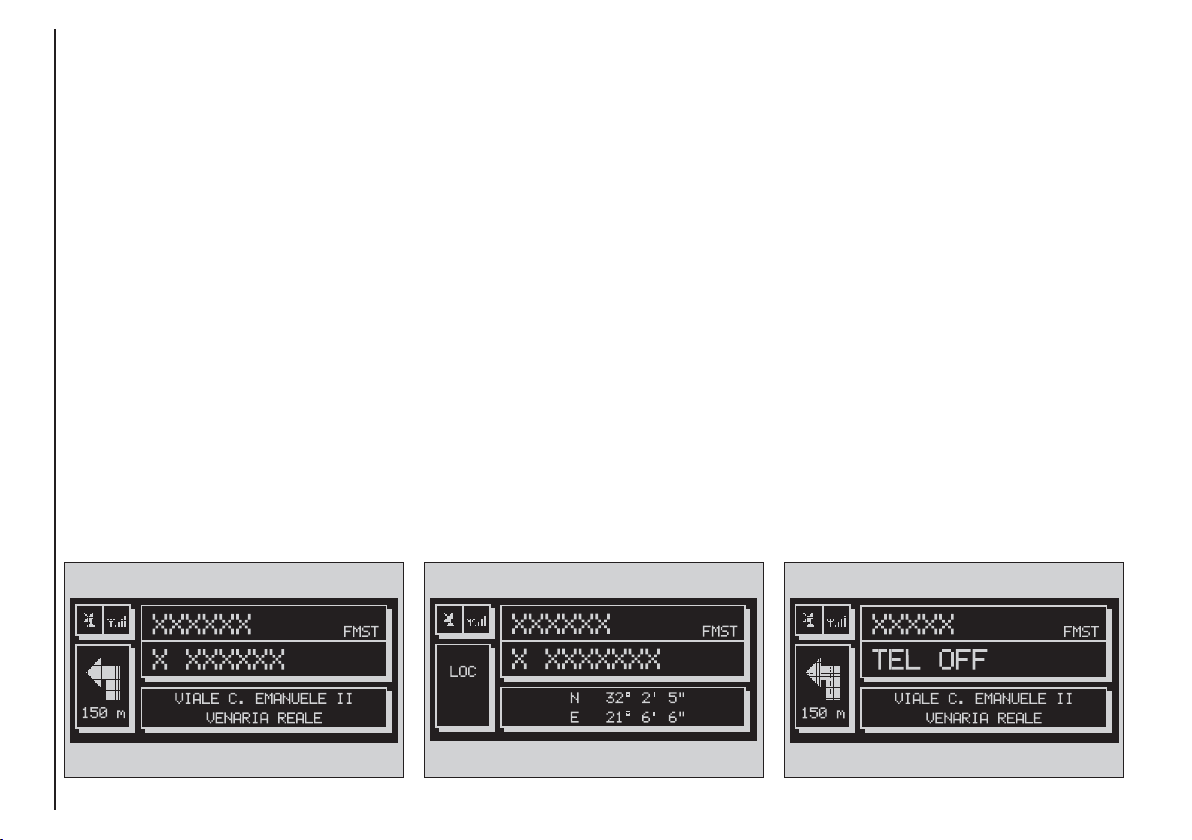
STANDARD INFORMATION
The display shows information rele-
vant to the main system modules:
– AUDIO
– TELEPHONE
– NAVIGATOR
Three fields are displayed fig. 4:
– Navigation: current vehicle position
(street and town), graphic symbol representing next manoeuvre and distance or position data if the navigation
CD ROM is not inserted, fig. 5.
– Telephone: GSM provider (if no
provider is present, then the display
shows “FIND…”. If phone is switched
off, the string will be “TEL OFF” fig. 6.
Active call forward arrow-shaped icon,
unread SMS message envelope-shaped
icon, field strength status bar.
– Audio source: RDS string, tuned
band and frequency, or CD playback
track.
In MAIN mode the following keys are
active: “SRC” 15-fig. 1 to select the required audio source, multifunction keys
1÷12-fig. 1 to activate the options
available in the selected audio source.
16
fig. 4
F0D2002g
fig. 5
F0D2130g
F0D2003g
fig. 6
Page 18
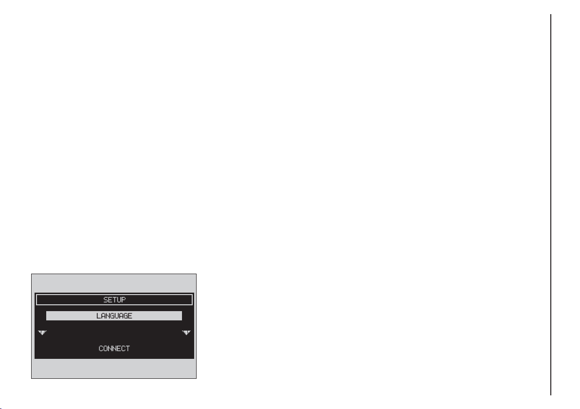
“SETUP” FUNCTION
The SETUP mode enables to set different vehicle and CONNECT system
operating modes and parameters.
To enter the SETUP mode, press the
MAIN button 17-fig. 1 and then the
knob 22-fig. 1, the display will show
the following menu fig. 7:
– LANGUAGE
– CONNECT.
F0D2161g
Select LANGUAGE by rotating knob
22-fig. 1 and confirm by depressing it.
Languages available with system will be
displayed: ITALIAN, GERMAN, ENGLISH, FRENCH, PORTUGUESE and
DUTCH; select the required language
by turning knob 22-fig 1, then depress
it to confirm the operation.
WARNING Change of language will
involve both the written text and the
language of vocal commands.
WARNING Before starting language
change procedure, be sure that the
provided SETUP CD is available and
ready to be used.
WARNING To change the language
the ignition key shall be at MAR and
the system shall be on.
A special message will then be displayed, asking the user to insert the
provided SETUP CD or to wait if the
SETUP CD is already inserted. A series
of messages will inform the user about
procedure progress and end: it is essential to not “disturb” the system during this operation.
CONNECT Nav
fig. 7
17
Page 19

Do not start the engine or disconnect
the battery during the language change
operation.
Should this take place, the first time
you turn the system on, a special message will be displayed communicating
CONNECT Nav
that the language change operation shall
be concluded inserting the SETUP CD:
“WARNING: LANGUAGE CHANGE
FAILED. PLEASE REPEAT PROCEDURE”.
Selecting CONNECT by turning and
pressing the knob 22-fig. 1, the display
will show the following submenu:
– VIDEO
– POWER OFF
– SERIAL DATA INTERFACE
– FLEET MANAGEMENT.
VIDEO
Selecting and confirming “VIDEO” by
rotating and pressing the knob 22-
fig. 1 will allow the following settings:
1) “DAYTIME BRIGHTNESS”: en-
ables to adjust the display brightness
in day mode. To perform the adjustment, select and confirm this option
by rotating and pressing the knob 22-
fig. 1. Rotate the knob 22-fig. 1
clockwise to increase brightness and
counterclockwise to decrease it.
2) “DAYTIME CONTRAST”: to ad-
just contrast in daytime brightness
mode. To perform the adjustment, select and confirm this option by rotating and pressing the knob 22-fig. 1.
Rotate the knob 22-fig. 1 clockwise
to increase contrast and counterclockwise to decrease it.
3) “NIGHTTIME BRIGHTNESS”:
enables to adjust the display brightness
in night mode. To perform the adjustment, select and confirm this option by rotating and pressing the knob
22-fig. 1. Rotate the knob 22-fig. 1
clockwise to increase brightness and
counterclockwise to decrease it.
4) “NIGHTTIME CONTRAST”: to
adjust contrast in nighttime brightness
mode. To perform the adjustment, select and confirm this option by rotating and pressing the knob 22-fig. 1.
Rotate the knob 22-fig. 1 clockwise
to increase contrast and counterclockwise to decrease it.
18
Page 20

5) “MODE, DIMMING, CON-
TRAST”: selecting and confirming this
option by rotating and pressing the
knob 22-fig. 1, the following settings
are possible:
“AUTOMATIC”: enables to adjust
automatically the day/night mode depending on vehicle lights switching
on/off.
“DAY”: activates day mode.
“NIGHT”: activates night mode.
After selecting the required setting,
press the knob 22-fig. 1 to confirm.
If the automatic mode is “DAY” only day adjustment is displayed and the
night one is deactivated.
If the automatic mode is “NIGHT”
only night adjustment is displayed and
the day one is deactivated.
POWER OFF
Select and confirm “POWER OFF”
by rotating and pressing the knob 22-
fig. 1 to access the type of setting that
determines CONNECT switching off
(dependent on or independent of ignition key).
Possible settings, only with ignition
key at MAR, are the following:
– “key-dependent auto-off”
– “key-independent auto-off”
Current activated setting will be high-
lighted.
Select and confirm the required set-
ting by rotating and pressing the knob
22-fig. 1.
SERIAL DATA INTERFACE
IMPORTANT The SERIAL DATA
INTERFACE function is not supported by system.
CONNECT Nav
19
Page 21
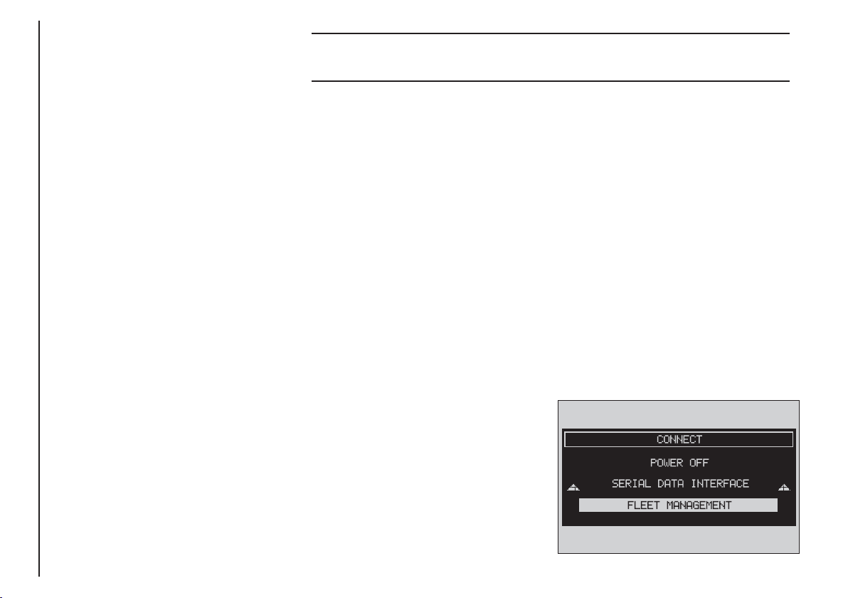
FLEET MANAGEMENT
When choosing this function, the
CONNECT Nav system sends automatically SMS messages (to a suitable
preset receiver, e.g. a control centre)
containing the position of the vehicle
CONNECT Nav
mounting the CONNECT Nav.
SMS messages are structured as follows:
– vehicle location (latitude and longitude)
– city (only with navigation CD inserted; if no CD is inserted, the field
is empty)
– street (only with navigation CD inserted; if no CD is inserted, the field
is empty)
– time and date
– vehicle ID (number plate).
Example: LT:-2.30000;LG:-2.40000; #Benevento;#
Via Basilio Giannelli;#S:30;M:20; H:19;ND:2;D:02;MH:10;Y:2001;#BR757AM;#
Latitude: -2.30000
Longitude: -2.40000
To activate the FLEET MANAGE-
MENT function, proceed as follows:
– press the “MAIN” button 17-fig. 1
City: Benevento
Street Via Basilio Giannelli
Time and date hour19.20 minutes,
30 seconds
Tuesday 2/10/2001
Number plate BR757AM
to display the main screen;
– turn and press the knob 22-fig. 1
to select and confirm “CONNECT”;
the display will show the “CONNECT” menu;
– turn and press the knob 22-fig. 1
to select and confirm “FLEET MANAGEMENT” fig. 8; the screen in fig. 9
If the navigation CD is inserted, the
will be displayed;
vehicle position is processed matching
coordinates with system maps.
In any case, navigation CD absence,
does not impair system operation.
The system will send the SMS message
F0D2160g
even if the GPS coverage is temporarily missing; in this case the vehicle position is calculated through the “dead
reckoning” procedure.
20
fig. 8
Page 22
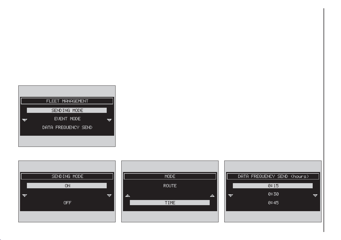
– select and confirm “Sending mode”
by rotating and pressing the knob 22-
fig. 1, the screen in fig. 10 will be displayed;
F0D2162g
– select and confirm “ON” (or
“OFF” if you want to deactivate it) by
rotating and pressing the knob 22-
fig. 1;
– turn the knob 22-fig. 1 to select
“EVENT MODE” then press the knob
to confirm; the condition shown in
fig. 11 will be displayed;
– turn the knob 22-fig. 1 to select
“ROUTE (km/mi)” or “TIME (hours)”,
then press the knob to confirm.
Selecting “ROUTE (km/mi)” the
message will be sent at the number
of km or miles set in “DATA FREQUENCY SEND”; selecting “TIME
(hours)” the message will be sent at
the number of hours set in “DATA
FREQUENCY SEND”;
– turn knob 22-fig. 1 to select “DATA FREQUENCY SEND” then press
to confirm; according to the previously
set parameter (route or time) the display will show the screen in fig. 12 or
fig. 13;
CONNECT Nav
fig. 9
fig. 10
F0D2163g
fig. 11
F0D2164g
fig. 12
F0D2165g
21
Page 23
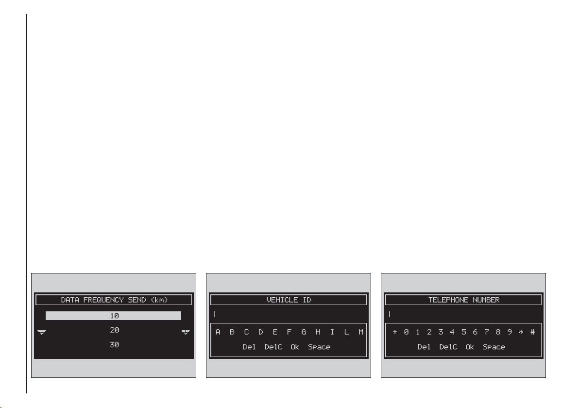
– turn knob 22-fig. 1 to select the
required value, then press to confirm;
– turn knob 22-fig. 1 to select “VE-
HICLE ID” then press to confirm; the
display will show the screen in fig. 14
and the keypad for typing in the vehi-
CONNECT Nav
cle identification data (e.g.: number
plate; turn knob 22-fig. 1 to select in
sequence the required digits and/or
letters, then press each time to confirm the character. Once you have
completed the vehicle ID, select “OK”
and press knob 22-fig. 1 the display
will return to the initial screen and the
field near “Vehicle ID” will show the
entered alphanumeric string;
– turn knob 22-fig. 1 to select
“TELEPHONE NUMBER”; the screen
in fig. 15 will be displayed together
with the alphanumeric keypad for dialling the required telephone number
to which SMS shall be sent; turn knob
22-fig. 1 to select in sequence the required numbers and press it to confirm each time. Once you have completed the telephone number, select
“OK” and press the knob 22-fig. 1;
the display will return to the initial
screen and the field near “TELEPHONE NUMBER” will show the entered number;
– turn knob 22-fig. 1 to select “OK”
then press the knob to confirm settings; the display will return to the initial screen.
22
fig. 13
F0D2168g
fig. 14
F0D2166g
F0D2167g
fig. 15
Page 24

Operation requirements
The “FLEET MANAGEMENT” function is operational if the following conditions are present:
– “FLEET MANAGEMENT” function
active;
– service centre telephone number
entered;
– vehicle ID entered;
– frequency set (time or route);
– CONNECT on;
– SIM card inserted;
– sufficient credit;
– GSM coverage.
Failing message sending
Should one or more of the following
conditions - e.g.: CONNECT off, SIM
card not inserted or disabled, insufficient GSM coverage - take place when
sending SMS messages, their regular
transmission will be impaired.
In this case the system will store the
messages and send them later (max.
10 messages) when normal operating
conditions are restored.
IMPORTANT More particularly,
the condition of CONNECT off will
store the messages with incorrect position, since the first position present
at system switching on will be detected.
CONNECT Nav
23
Page 25
AAUUDDIIO
O
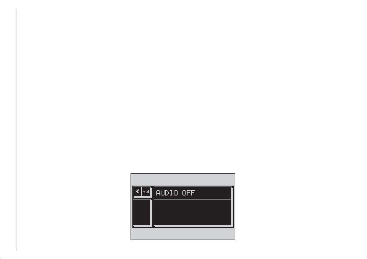
The audio system is turned on by
pressing briefly the “AUDIO” button18-fig. 1 which displays the main
CONNECT Nav
functions of the radio.
Keeping the “AUDIO” button 18-
fig. 1, pressed longer, with the audio
system on and any operating mode active, the “stand-by” mode is switched
on: this way the radio is turned off and
the display shows the message “AUDIO OFF” fig. 16. To turn the radio
on again, briefly press the “AUDIO”
button 18-fig. 1, thus reactivating the
audio function with the corresponding
screen.
Through the audio system it is possible to control:
– RDS radio with FM/AM reception;
– Compact Disc player;
– equalizer;
– MP3 player.
F0D2004g
SCREEN OPTIONS
AND FUNCTIONS
Pressing repeatedly the “SRC” key 3-
fig. 1 the available audio sources are
displayed cyclically:
– Radio (FM1, FM2, FM3, FMST, LW,
MW, AMST)
– CD / NO CD (if CD is inserted or
not).
The audio source is automatically
changed in one of the following cases:
– broadcasting of traffic information,
if the TA function is on and an enabled
station is tuned (TP)
– forwarding a phone call
– receiving a phone call
– voice recognition function activation.
24
fig. 16
Page 26
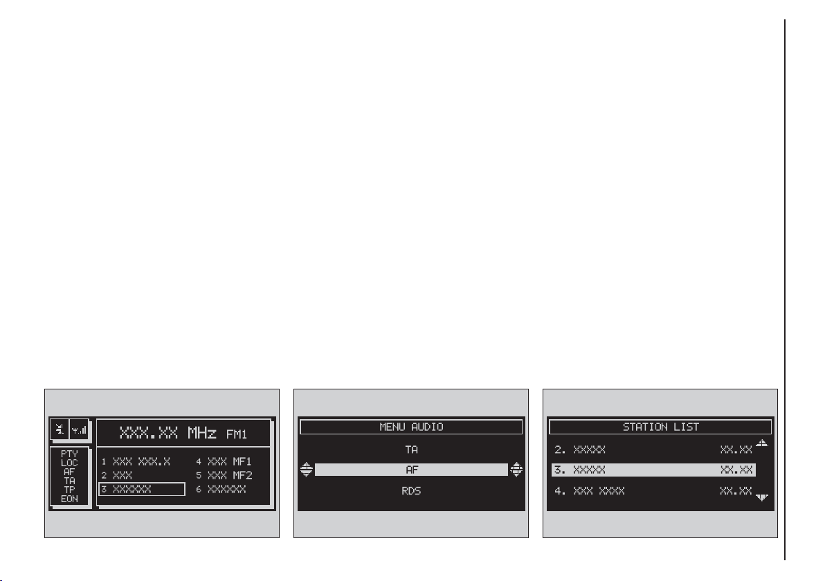
RADIO MODE
If the active source is FM radio (FM
1/2/3), the display will show the current radio status fig. 17:
– Active frequency band FM: FM1,
FM2, FM3.
– Tuned station frequency.
– Frequency measure unit (MHz).
– Stored station frequency and RDS
channel name.
– Vertically, on the right window:
chosen PTY (if any), AF, tuner sensitivity (LOC “low sensitivity”, DX “high
sensitivity”), MONO/STEREO, TA,
TP, EON.
The lower side of the front panel fea-
tures 12 multifunction keys:
– 1..6 ((short push): to select a previously stored station; there are 6
available memories for each band (FM
1/2/3, LW, MW).
– 1..6 (long push): to store the current station.
Press the knob 22-fig. 1 to display the
main audio menu with the following options, fig. 18:
– TA: to enable/disable traffic announcement.
– AF: to enable/disable alternative
frequency function.
– RDS: to enable (“YES”) disable
(“NO”) the RDS function.
– PTY-PROG. TYPE: to select the required PTY code (channel filter)
through a list of 32 available codes.
– AUTOSTORE: to store automatically the six stations with the strongest
signal in the frequency band tuned.
– BAND SCAN: to play for 10 seconds the radio stations in the band
tuned.
– PRESET SCAN: to play for 10 seconds the radio stations stored in the
band tuned.
– STATION LIST: to list the radio
stations previously stored in the band
tuned, and to list also the RDS codes
and frequencies fig. 19.
CONNECT Nav
fig. 17
F0D2005g
fig. 18
F0D2006g
fig. 19
F0D2007g
25
Page 27
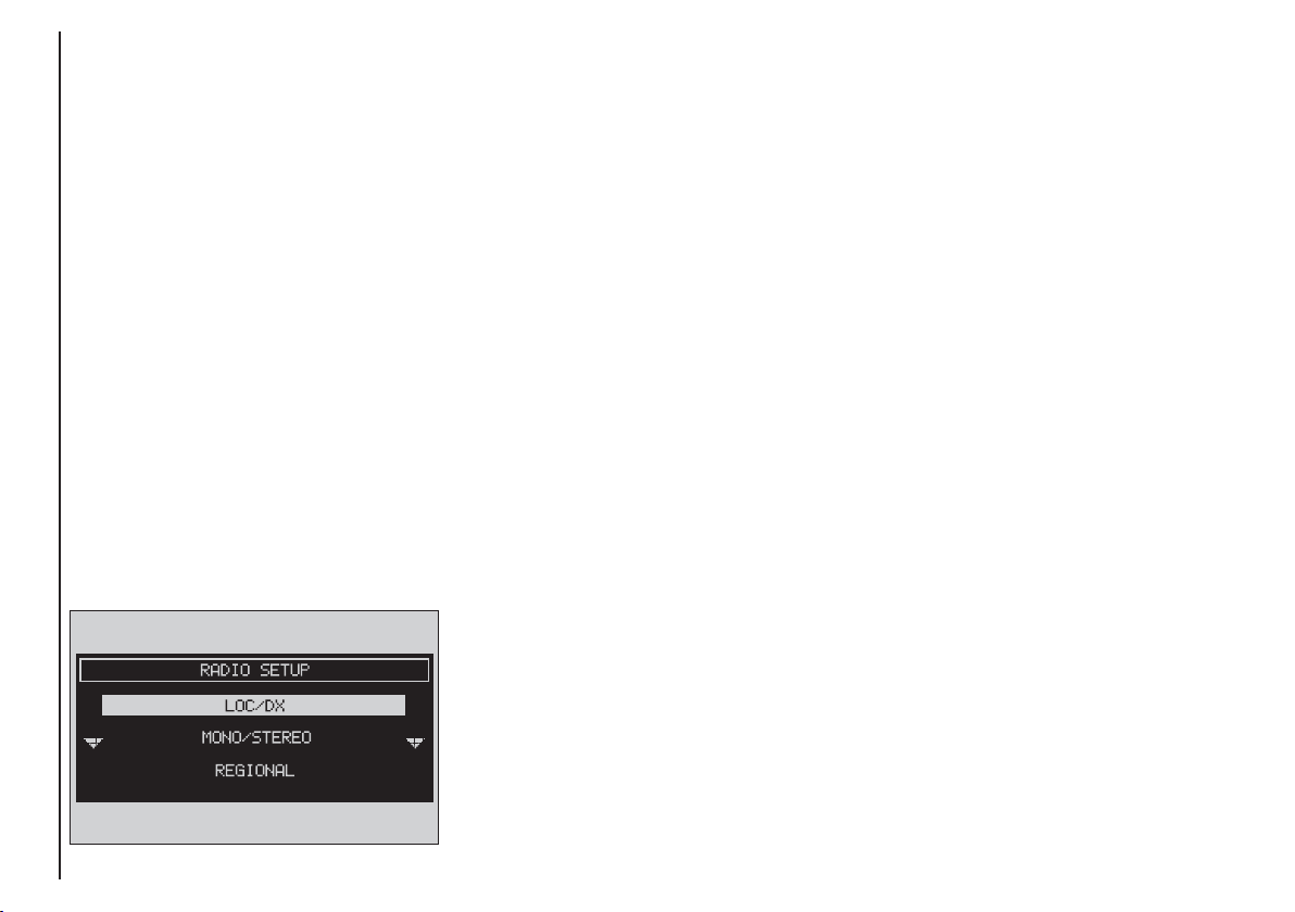
– RADIO SETUP: to display the radio
setup menu with the following options
fig. 20:
LOC/DX
: to change tuner sensitivity
for searching stations (LOC for “low
sensitivity”, DX for “high sensitivity” -
CONNECT Nav
only available in FM band).
MONO/STEREO
: to enable/disable
stereo playback, (only available in FM
band).
REGIONAL
: to enable/disable RDS REGIONAL function, (only available in
FM band).
– NEWS: to enable/disable PTY
NEWS function, (only available in FM
band).
F0D2008g
– AUDIO SETUP: to display the audio setup menu; for detailed description of the different menu functions,
see the relevant paragraph in chapter
“AUDIO SETTINGS”.
The front panel keys are the following:
÷
and
˜
–
(short push): backward or forward 50 kHz skip from the
current tuned frequency;
÷
and ˜(long push): tuning to
–
next or previous station, according to
active filters (TA, PTY). When searching stations, the RDS code is replaced
by string “SEEK+ or SEEK-”.
MANUAL TUNING
This allows manual station searching
in the chosen band.
Proceed as follows:
– select the frequency band (FM1,
FM2, FM3, MW, LW) pressing the
“SRC” key 15-fig. 1 repeatedly;
÷
– briefly press key “
” 11-fig. 1 or
“˜” 12-fig. 1 to start the search for
tuning the previous or next station
that can be received.
26
fig. 20
Page 28

AUTOMATIC TUNING
This function seeks automatically sta-
tions in the chosen band.
Proceed as follows:
– select the frequency band (FM1,
FM2, FM3, MW, LW) pressing repeatedly the “SRC” key 15-fig. 1;
÷
– press “
” 11-fig. 1 or “˜” 12-
fig. 1 to start the search for tuning the
previous or next station that can be
received.
If the “TA” function is on (traffic information), the tuner only seeks stations that broadcast traffic bulletins.
If the “PTY” function is on, the tuner
only seeks PTY stations.
MANUAL STATION
STORAGE
The station being heard can be
stored in the range chosen with the
multifunction keys 1÷ 6-fig. 1.
Keep one of these keys pressed until
the display shows the number of the key
with which the station has been stored.
A confirmation beep will indicate that
the station has been stored.
LISTENING TO STORED
STATIONS
Proceed as follows:
– choose the required frequency
band (FM1, FM2, FM3, FMST, LW,
MW or AMST) pressing repeatedly
the “SRC” key 15-fig. 1;
– press briefly one of the multifunction keys 1÷ 6-fig. 1.
In the FM1, FM2, FM3 and FMST
bands, if reception is poor and the
“AF” alternative frequency seek function is on, a station with the strongest
signal that is broadcasting the same
programme is automatically sought.
CONNECT Nav
27
Page 29

“AUDIO SETUP” FUNCTION
(AUDIO ADJUSTMENTS)
Audio parameters can be activated
and adjusted in the same way with all
the audio sources (Radio, CD, CD-
CONNECT Nav
Changer and MP3).
Adjustment procedure is described
in the relevant paragraph in section
“AUDIO SETTINGS”.
“TA” FUNCTION
(TRAFFIC INFORMATION)
Certain stations in the FM band
(FM1, FM2, FM3 and FMST) are also
enabled to broadcast information
about the conditions of the traffic. In
this case the displays shows the abbreviation “TP”.
To turn on/off the TA function (Traffic Announcement) for traffic bulletins,
press the knob 22-fig. 1 from the main
audio menu fig. 18. Turn and press the
knob 22-fig. 1 to select “TA”. Select
“ENABLED” or “DISABLED” and then
press the knob again.
When the TA function is on, the display shows “TA” at the bottom of the
main screen on the left side.
The listening conditions and information shown on the display may be
the following:
– TA and TP: you are tuned to a station that broadcasts traffic information
and the traffic information function is on
– TP: you are tuned to a station that
broadcasts traffic information but the
traffic information function is off
– TA: the traffic information function
is on but you are tuned to a station
that does not broadcast traffic information
– TA and TP not shown on the display:
you are tuned to a station that does not
broadcast traffic information and the
traffic information function is off.
With the TA function on it is possible:
1) to search stations broadcasting
traffic info only in the FM band;
2) to receive traffic information al-
so if the CD/MP3 player is working;
3) to receive traffic information at a
preset minimum level also with the radio completely muted.
28
Page 30

The operations to be carried out for
each of the above described conditions
are listed below.
1) To receive stations enabled to
broadcast traffic information:
– choose band FM1, FM2 or FM3;
– turn on the TA function so that the
display shows “TA”;
– start seeking the frequencies.
2) If you wish to receive traffic infor-
mation while listening to a CD, before
inserting the CD, tune to a station enabled to broadcast traffic information
(TP) and turn the TA function on. If,
while playing the CD, this station
broadcasts traffic information, CD
playing will be temporarily stopped and
resumed automatically at the end of
the message.
If the CD player is already working
and at the same time you wish to receive traffic information, turning on the
TA function, the radio tunes to the last
station heard in the FM band and the
traffic announcements are transmitted.
If the station selected does not broadcast traffic information, an enabled station is sought automatically.
To stop traffic announcement, turn
off the TA function while receiving traffic messages.
If the tuned station belongs to the
EON (ENHANCED OTHER NETWORK) circuit, the display will show
“EON”
A telephone call has higher priority
than traffic message.
IMPORTANT In certain countries,
radio stations exist which though the
TP function is active (the display shows
“TP”), do not broadcast traffic information.
If the radio is working in the AM
band, choosing the FM band tunes to
the last station heard. If the chosen
station does not broadcast traffic information (“TP” not shown on the display), an automatic search is started
for an enabled station.
If the volume is changed during a traffic bulletin the value is not shown on
the display and the new value is kept
only for the bulletin in progress.
IMPORTANT If the TA function is
on and the station tuned is not enabled
to provide traffic information or is no
longer able to broadcast this information (the display does not show “TP”),
after about 1 minute in which the radio is in these conditions:
– if a CD is being played another station enabled to broadcast traffic information is sought automatically.
CONNECT Nav
29
Page 31

“AF” FUNCTION
(SEEKING ALTERNATIVE
FREQUENCIES)
Within the RDS system the radio can
work in two different modes:
CONNECT Nav
– AF ENABLED: alternative fre-
quency search on;
– AF DISABLED: alternative fre-
quency search off.
When the signal of the RDS station
tuned weakens, the following two cases may occur:
– With AF ENABLED the RDS system activates automatic tuning of the
optimum frequency of the station chosen, with the stations enabled, therefore the radio is automatically tuned
to the station with the strongest signal that is broadcasting the same programme. During the journey it will
thus be possible to continue listening
to the station chosen without having
to change the frequency when changing area. Of course, the station being
listened to must be receivable in the
area the vehicle is crossing.
– With AF DISABLED the radio will
not tune the strongest station automatically and it will have to be found
manually using the tuner buttons.
To turn the “AF” function on/off, select and confirm “AF” by the knob 22-
fig. 1, from the main audio menu
fig. 18. Then, select and confirm “EN-
ABLED” or “DISABLED” by the knob
22-fig. 1.
When the AF function is on, “AF” is
displayed in the vertical list of main audio screen.
The RDS channel name (if available)
is still shown on the display.
“RDS” FUNCTION
The “RDS” function enables/disables
RDS string (showing the tuned station
name) display.
To turn the “RDS” function on/off,
select “RDS” by the knob22-fig. 1
from the main audio menu fig. 18,
then press the knob to select “YES” or
“NO”.
When the “RDS” function is on, the
display shows the string with tuned station name.
30
Page 32

“PTY-PROG. TYPE”
FUNCTION (CHOOSING A
TYPE OF PROGRAMME)
The “PTY-PROG. TYPE”, function,
when present, makes it possible to
give priority to broadcasters transmitting programmes classified according to the type of PTY. PTY programmes may concern emergency announcements or various subjects (e.g.
music, news). To access the list of PTY
programmes, choose and confirm
“PTY-PROG. TYPE” with the knob 22-
fig. 1 from the main audio menu
fig. 18; the display will show the
screen with the list of PTY programmes and the subject of the last
station heard (e.g “NEWS”). To scroll
the list of PTY programmes, turn the
knob 22-fig. 1. To choose a type of
programme, press the knob after
choosing the required type of programme.
IMPORTANT The PTY function
can only be turned on in the FM band.
The list of PTY programmes is the
following:
NO PTY
–
–
NEWS
–
AFFAIRS
–
INFO
–
SPORT
–
EDUCATE
–
DRAMA
–
CULTURE
–
SCIENCE
–
MISC
–
POP M
–
ROCK M
–
EASY M
–
LIGHT M
–
CLASSICS M
–
OTHER M
–
WEATHER
–
FINANCE
–
CHILDREN
–
SOCIAL
–
RELIGION
–
PHONE IN
–
TRAVEL
–
LEISURE
–
JAZZ
–
COUNTRY
–
NATION M
–
OLDIES
–
FOLK M
–
DOCUMENT
–
TEST
–
ALARM
.
To store the station tuned, press one
of the 6 multifunction keys 1 ÷ 6-
fig. 1 for over two seconds.
To seek a station with this programme, follow the instructions given in the “AUTOMATIC TUNING”
paragraph.
If no station is available with this type
of programme, the station selected
previously is returned. Select “NO
PTY” if you do not wish to set a programme type.
CONNECT Nav
31
Page 33

“AUTOSTORE” FUNCTION
(AUTOMATIC STATION
STORAGE)
After selecting the AMST or FMST
band, to turn on the Autostore func-
CONNECT Nav
tion (automatic station storage), select
and confirm “AUTOSTORE” with the
knob 22-fig. 1.
When this function is on, the radio
automatically stores the stations with
the strongest signal:
– 6 FM stations in the FMST band or
– 6 AM stations in the AMST band.
Stations will be stored automatically
on the multifunction keys 1 ÷ 6-fig. 1.
After storage, the radio tunes automatically to the first station of the
FMAST band, corresponding to the frequency stored on the multifunction key
1-fig. 1.
Every station is stored only once, except in the case of regional programmes which in certain cases might
be stored twice.
The behaviour of the set during Autostore is as follows:
– at the beginning of the Autostore
function all the other functions are disabled
– any change in volume is not shown
on the display
– pressing one of the multifunction
keys 1 ÷ 6-fig. 1 the automatic storage process is interrupted and the station stored with that key is tuned
– selecting and activating a radio
function (e.g. PTY) the automatic storage process is interrupted, the last station heard before tuning on Autostore
is tuned and the function associated
with the key pressed is run
– selecting and activating one or both
TA/AF functions during the automatic storage process, automatic storage
will be interrupted, the TA (traffic information) and AF (alternative frequencies) functions will be turned
on/off and a new automatic storage
process will be started
– changing the audio source (Radio,
CD) during the automatic storage
process, the Autostore function is interrupted.
IMPORTANT It may occur that
the Autostore function is unable to
find 6 stations with a strong signal; in
this case only the stations found are
stored.
IMPORTANT Activating the “Autostore” function cancels the stations
stored previously in the FMST or
AMST band.
32
Page 34

“BAND SCAN” FUNCTION
The “BAND SCAN” function activates station scanning in the chosen
frequency band. Each station frequency will be displayed for about 10 seconds.
To turn on the “BAND SCAN” function, select and confirm “BAND
SCAN” with the knob 22-fig. 1 from
the main audio menu.
During scanning, the display will
show “BAND SCAN”.
To stop the band scan function, press
“ESC” 23-fig. 1.
“PRESET SCAN” FUNCTION
The “PRESET SCAN” function activates stored station scanning in the
chosen frequency band. Each stored
station will be played for about 10 seconds.
To turn on the “PRESET SCAN”
function, select and confirm “PRESET
SCAN” with the knob 22-fig. 1, from
the main audio menu.
During scanning, the display will show
“PRES. SCAN”. To stop the band scan
function, press “ESC” 23-fig. 1.
“STATION LIST” FUNCTION
The “STATION LIST” function displays a screen fig. 19, listing the radio stations previously stored in the
tuned band, the RDS codes and the
corresponding frequencies.
To turn this function on, select and
confirm “STATION LIST” with the
knob 22-fig. 1 from the main audio
menu. To scroll the stored station list
use the encoder 14-fig. 1.
“RADIO SETUP” FUNCTION
To turn this function on, select and
confirm “RADIO SETUP” with the
knob 22-fig. 1 from the main audio
menu.
This function enables to go to next
window to adjust radio settings. When
in this window it is not possible to
change the audio source. The following functions are displayed:
– LOC/DX
– MONO/STEREO
– REGIONAL
– NEWS.
CONNECT Nav
33
Page 35

“LOC/DX” FUNCTION
(TUNER SENSITIVITY
ADJUSTMENT)
With this function it is possible to
change the sensitivity of automatic ra-
CONNECT Nav
dio station searching. When low sensitivity “LOC” is set, only stations with
excellent reception are sought; when
high sensitivity “DX” is set, all the stations are sought. If you are in an area
with a large number of broadcasters
and you want the ones with the
strongest signal, choose low sensitivity “LOC”.
To choose between low or high
tuner sensitivity, press the knob 22-
fig. 1 after selecting “LOC/DX” by
turning the knob. The abbreviation of
the sensitivity chosen will be shown on
the display:
– LOC = low sensitivity;
– DX = high sensitivity.
Select the required item and then
press the knob 22-fig. 1 to confirm.
“MONO/STEREO” FUNCTION
To turn on/off the Stereo function
(stereo station reception) press the
knob 22-fig. 1 after selecting “MONO/
STEREO” with the knob. Select and
confirm “STEREO or “MONO” by
turning and pressing the knob 22-
fig. 1.
This function is only available on FM
band.
When the signal of the station tuned
is weak, to improve the sound quality, it is advisable to switch to
“MONO”.
“REGIONAL” FUNCTION
This function enables or disables a
RDS regional service.
To turn this function on/off, select
and confirm “REGIONAL” with the
knob 22-fig. 1.
Select “ENABLED” or “DISABLED”
rotating and pressing the knob 22-
fig. 1 to confirm.
This function is only available on FM
band.
34
Page 36

“NEWS” FUNCTION
This function shortly enables or not
the PTY code News.
To turn this function on/off, select
and confirm “NEWS” with the knob
22-fig. 1.
Select “ENABLED” or “DISABLED”
rotating and pressing the knob 22-
fig. 1 to confirm.
This function is only available on FM
band.
F0D2009g
If the tuned band is AM, the display
shows a screen like that displayed for
the FM band but with the following differences fig. 21 - 22.
– TA, AF, RDS and PTY functions are
not present.
– Certain information concerning the
station (stereo signal, TP code, EON,
TMC, PTY) are not present.
– Frequency unit is changed (kHz).
F0D2010g
CD MODE
To guarantee optimum playing, use
original CDs. If using R/RW CDs, use
top quality CDs duplicated at as low
as possible speed.
IMPORTANT Never use 8 mm audio or MP3 CDs, even with the specific adapter, since this format will
damage the system.
Choosing the CD source with the
“SRC” key 15-fig. 1, will display a
screen with the following options
fig. 23:
– Audio source: CD.
– CD name (if set).
– “TA”, if traffic announcement function is on.
– Track and time information.
F0D2011g
CONNECT Nav
fig. 21
fig. 22
fig. 23
35
Page 37

– Current status of CD (play ˙,
pause II, stop ~).
– CD time information. If the CD is
not inserted, the display will show the
message “NO CD” “NO CD-DA” and
all CD options are disabled.
CONNECT Nav
– SCAN, if the SCAN function is on.
– SFL, if the SHUFFLE function is on.
– RPT ONE /REPEAT ALL, if the relevant functions are on.
– PROG, if the PROG function is on.
The front panel keys are the following:
÷ 11/˜ 12: to select previous or
next CD track;
II˙ 10 (short push): to play or stop
the CD;
II˙ 10 (long push): to pause the CD.
Press the knob 22-fig. 1 to display
the following options:
– CD SHUFFLE
– CD TA
– CD REPEAT
– CD PROG
– CD SCAN
– CD COMPRESSION
– CD SETUP
– AUDIO SETUP.
“CD SHUFFLE” FUNCTION
(RANDOM PLAYING)
To turn the “SHUFFLE” function
on/off, press the knob 22-fig. 1, after
selecting “SHUFFLE” with the knob.
Select and confirm “YES” or “NO” by
rotating and pressing the knob 22-
fig. 1. When the Shuffle function is on,
the display shows “SFL”.
With this function on, the CD tracks
are played in random sequence. To
turn off this function select “NO” with
the same above described procedure.
“CD TA” FUNCTION
(TRAFFIC INFORMATION)
To turn the TA function (Traffic Announcement) on/off while listening to
a CD, select and confirm “CD TA”
with the knob 22-fig. 1 .
When the “TA” function is on, the
main screen displays “TA”.
For the description of the function,
refer to the corresponding paragraph
in the “RADIO MODE” chapter.
36
Page 38

“CD REPEAT” FUNCTION
To activate this function, press the
knob 22-fig. 1, after selecting “CD REPEAT” by turning the knob. The display shows “NO REPEAT”, “REPEAT
ONE” and “REPEAT ALL”.
– “NO REPEAT”: repeat function off
– “REPEAT ONE”: repeat one CD
track
– “REPEAT ALL”: repeat all CD
tracks
Select and confirm the required item
by turning and pressing the knob 22-
fig. 1.
When “REPEAT ONE” or “REPEAT
ALL” is on, the display shows “RPT”.
“CD PROG” FUNCTION
To turn the “CD PROG” function
on/off, rotate and press the knob 22-
fig. 1 after selecting the function.
This function enables or disables playback of the previously user programmed track list (see “CD SETUP”
functions).
The “CD PROG” function is disabled
if no programmed list has been entered.
“CD SCAN” FUNCTION
(BRIEF PLAYBACK)
To turn the “SCAN” function on/off,
rotate and press the knob 22-fig. 1
after selecting the function.
When this function is on, all the CD
tracks are played for about 10 seconds
in the actual sequence on the CD.
“CD COMPRESSION”
FUNCTION
This function activates dynamic
sound compression when playing a
CD in the vehicle.
To turn this function on/off, select
and confirm “COMPRESSION” with
the knob 22-fig. 1.
Select “YES” or “NO” to turn this
function on or off.
Select the required option with the
knob 22-fig. 1, then press it to confirm.
CONNECT Nav
37
Page 39

“CD SETUP” MENU
Select and confirm “CD SETUP”
with the knob 22-fig. 1 to display the
following menu fig. 24:
– CD TIME MODE
CONNECT Nav
– CD PROG
– CD NAME
– CD INFO
– OK.
“CD TIME MODE” function
The “CD TIME MODE” function defines time information about the CD
shown on the display:
– “TRACK ELAPSED TIME” (time
elapsed from start of track) (standard
function)
– (*) “TOTAL ELAPSED TIME” (total time elapsed from start of CD)
– (*) “TOTAL REMAINING TIME”
(total remaining time to the end of CD)
To activate new settings, select “OK”
from the CD SETUP menu.
(*) Option not available when the “Shuffle”
function is active.
“CD PROG” function
Selecting and confirming “CD
PROG” with the knob 22-fig. 1 will
display a numeric keypad fig. 25.
The “CD PROG” function is active only
when CD is stopped (“Stop”).
Use the knob 22-fig. 1 to select the
number of the track you want to add
to the programming sequence. Turn
the knob 22-fig. 1 to select the required number and then press it to
confirm.
“Scroll”
The “Scroll” function shall be used to
select the tracks not displayed.
38
fig. 24
F0D2012g
F0D2013g
fig. 25
Page 40

To turn this function on, select and
confirm “Scroll” rotating and pressing
the knob 22-fig. 1. With this function
on, rotate the knob 22-fig. 1 to dis-
play the remaining track list; press the
knob again to turn this function off.
“DelC” (DELETE)
The “DelC” function enables to clear
off the last stored track.
This function is disabled if the se-
quence is empty.
To turn this function on, select and
confirm “DelC” rotating and pressing
the knob 22-fig. 1.
“
Del” (DELETE ALL)
The “Del” function enables to delete
the entire track list stored.
This function is disabled if the se-
quence is empty.
To turn this function on, select and
confirm “Del” rotating and pressing
the knob 22-fig. 1.
“OK”
To confirm the prog sequence select
“OK” with the knob 22-fig. 1 and
then press it to confirm.
“CD NAME” function
If the CD already has a name, this will
be shown on the display.
The “CD NAME” function allows to
name max. 30 CDs with 20 characters
max.
Selecting the “CD NAME” function
by rotating and pressing the knob 22-
fig. 1 goes to the following submenu
fig. 26:
– CD NAME
– SEQUENCE
– DELETE
– DELETE NAME
– OK.
“CD NAME” is active only if CD is
stopped (“Stop”).
F0D2014g
CONNECT Nav
fig. 26
39
Page 41

“
CD NAME
”
Select “CD NAME” with the knob
22-fig. 1, in this way you go to a
screen showing an alphanumeric sequence to be used to name the CD inserted fig. 27.
CONNECT Nav
Proceed as follows:
– select the first letter rotating the
knob 22-fig. 1;
– press the knob to confirm;
– proceed in the same way for the
other letters until completing the
name
– select “OK” and press the knob 22-
fig. 1 to confirm the CD name.
After confirming the CD name, the
previous screen is shown automatically.
F0D2015g
The CD name is automatically associated to CD track number and total
time duration.
SEQUENCE
“
”
Selecting and confirming “SEQUENCE” with the knob 22-fig. 1
gives access to a menu with the option
to associate a name to a preset track
sequence.
Proceed as described before.
DELETE
“
”
This function enables to clear the CD
name and track sequence.
To turn this function on, select and
confirm “DELETE” rotating and pressing the knob 22-fig. 1. Before deleting the system will ask for confirmation.
DELETE NAME
“
”
This function enables to delete a pre-
viously stored sequence name.
With this function it is possible to
delete a specific CD programming sequence although another CD is inserted in the player.
40
fig. 27
Page 42

Selecting “DELETE NAME” rotating
the knob 22-fig. 1 will display the list
of programmed CDs. Select the CD
name to be deleted with the knob 22-
fig. 1 and then press it to delete. Select “OK” to confirm.
“
OK
”
To confirm your choices, select and
confirm “OK” with the knob 22-fig. 1;
the name and the associated sequence
will be stored or deleted.
IMPORTANT In case of buffer full,
a warning message “WARNING,
MEMORY FULL” will be displayed to
point out the problem. The user shall
have to delete some previously stored
CD names.
“CD INFO” function
Selecting and confirming “CD INFO”
with the knob 22-fig. 1, will display
a screen with the following information:
– CD name;
– track sequence (if defined).
“AUDIO SETUP” FUNCTION
(AUDIO ADJUSTMENTS)
To access the audio setup menu
while listening to a CD, select and confirm “AUDIO SETUP” with the knob
22-fig. 1.
For the description of the different
functions available in the menu, see the
corresponding paragraph of the “AUDIO SETTINGS” chapter.
CONNECT Nav
41
Page 43

AUDIO SETTINGS
The audio parameters described in this
paragraph can be activated and adjusted with all the audio sources (Radio,
CD).
CONNECT Nav
To display the main menu press the
knob 22-fig. 1, with any audio source
on.
Selezionare tramite la manopola 22-
fig. 1 la funzione “AUDIO SETUP” dal
menu principale di una delle sorgenti
audio e confermarla premendo la stessa. In questo modo si accede al seguente
menù fig. 28:
– INFO
– BASS
– TREBLE
– LOUDNESS
– EQUALIZER
– MANUAL EQUALIZER
– AUTO VOL. CONT.
– BALANCE/FADER
– AUTOCLIP DETECT
– MAX. VOL. AT ON
– OK.
Audio parameters will change as
soon as setting is performed.
INFO
This function displays a summary of
the selected audio parameters fig. 29.
BASS
(Bass adjustment)
Proceed as follows:
– select “BASS” turning the knob 22-
fig. 1;
– press the knob to confirm;
– turn the knob 22-fig. 1 right to in-
crease the bass tones or left to reduce
them.
At the end press the knob to confirm
and continue with the other parameter settings.
42
fig. 28
F0D2016g
F0D2017g
fig. 29
Page 44

TREBLE fig. 30
(Treble adjustment)
Proceed as follows:
– select “TREBLE” turning the knob
22-fig. 1;
– press the knob to confirm;
– turn the knob 22-fig. 1 right to in-
crease the treble tones or left to reduce them.
At the end press the knob to confirm
and continue with the other parameter settings.
F0D2018g
LOUDNESS
This function improves the level of
the sound when listening at low volume, increasing the bass and treble
tones.
To turn the function on and off, select and confirm “LOUDNESS” with
the knob 22-fig. 1.
EQUALIZER
With this function it is possible to
choose, among the predefined equalizer settings, the most appropriate one
for the music being listened to.
The predefined settings are:
– EQUALIZER OFF = standard setting
– BEST = best setting for listening to
music in the vehicle
– ROCK = setting for Rock music
– CLASSIC = setting for classical music
– JAZZ = setting for Jazz music
– MANUAL = personalised settings
obtained through the “MANUAL
EQUALIZER” function.
CONNECT Nav
fig. 30
43
Page 45

To activate the chosen setting, pro-
ceed as follows:
– select and confirm “EQUALIZER”
rotating and pressing the knob 22-
fig. 1;
CONNECT Nav
– turn and press the knob for the re-
quired setting.
A change in the treble and bass setting (Treble/Bass) will turn off the
equalizer.
MANUAL EQUALIZER
This function allows manual adjustment of the 5 equalizer frequency
bands and deactivates the treble and
bass settings (Treble/Bass).
Proceed as follows fig. 31:
– select and confirm “MANUAL
EQUALIZER” rotating and pressing the
knob 22-fig. 1;
– turn the knob 22-fig. 1 to select
the frequency band to be adjusted
(80Hz, 250Hz, 1kHz, 4kHz, 12kHz),
then confirm by pressing the knob;
F0D2019g
– adjust the band selected turning
and pressing the knob 22-fig. 1;
– after adjusting all the bands, choose
“OK” with the knob 22-fig. 1, then
press the knob to confirm and go back
to the previous screen.
If “ESC” is pressed 23-fig. 1 you go
back to the previous screen with the
settings stored previously.
44
fig. 31
Page 46

AUTO VOL. CONT.
(volume changing with speed)
With the “AUTO VOL. CONT.”
function it is possible to automatically adjust the radio volume level to the
speed of the vehicle, increasing it as
the speed increases to maintain the
correct ratio with the noise level in
the passenger compartment.
The adjustment levels available are:
– OFF (function off)
– 1 (MIN) (min. volume)
– 2
– 3
– 4
– 5
– 6
– 7 (MAX) (max. volume).
To turn the function on/off or enter
the setting, proceed as follows:
– select and confirm “AUTO VOL.
CONT.” rotating and pressing the
knob 22-fig. 1;
– turn the knob 22-fig. 1 to select a
setting or turn the function off, then
press the knob to confirm.
F0D2020g
BALANCE / FADER fig 32
(sound distribution)
The “BALANCE/FADER” function
shows a schematic representation of
the position of the speakers in the vehicle (left/right and front/rear). Sound
distribution is represented by a red
small square cursor.
To adjust sound distribution, proceed as follows:
– select and confirm
“BALANCE/FADER” rotating and
pressing the knob 22-fig. 1, the display
shows the screen in fig. 33.
F0D2132g
CONNECT Nav
fig. 32
fig. 33
45
Page 47

– turn and press the knob 22-fig. 1
to select and confirm “BALANCE”,
the function that changes the sound
distribution in the passenger compartment between the right and left
speakers, the display will show the
CONNECT Nav
screen in fig. 33.
– turn the knob 22-fig. 1 to change
the sound distribution in the passenger
compartment between the right and
left speakers (cursor moving along the
horizontal axis), then press the knob
to confirm.
In the same way, choose and confirm
the “FADER” function to change the
sound distribution between the front
and rear speakers (cursor moving
along the vertical axis).
After adjustment, select “OK” with
the knob 22-fig. 1 and then press it to
confirm the setting and to go back to
the previous screen.
If “ESC” 23-fig. 1 is pressed you go
back to the previous screen with the
settings stored previously.
AUTOCLIP DETECT
(dynamic distortion limiter)
With the “AUTOCLIP DETECT”
function the radio output level is reduced automatically when excessive
distortion level (that could damage the
speakers) is detected.
To turn this function on and off, select “AUTOCLIP DETECT” with the
knob 22-fig. 1, then press it to confirm. The function status (on or off) is
shown on the display by wording
“YES” or “NO”.
MAX. VOL. AT ON
The “MAX. VOL. AT ON” function
clips radio volume (at level 10) at power on. If the radio was switched off
with a volume setting higher than 10,
when activating this function (ignition
key at STOP, at power on the volume is reset to the above limit.
To turn this function on and off, select and confirm “MAX. VOL. AT
ON” rotating and pressing the knob
22-fig. 1.
“OK”
At the end, select “OK” with the
knob 22-fig. 1 and then press it to
confirm and go back to the main “AUDIO SETUP” menu.
46
Page 48

MP3 MODE
To guarantee optimum playing, use
top quality CDs duplicated at as low
as possible speed.
The system can recognize the type
of Compact Disc inserted.
During the reading procedure to recognize the disk the display shows
“WARNING - Reading CD. Please
wait” and then “Exploring MP3..”.
IMPORTANT Never use 8 cm audio or MP3 CDs, even with the specific adapter, since this format will
damage the system.
IMPORTANT The system builds
MP3 CD folder-organized structure of
files; folders are organized in sequence
with their own mp3 tracks (up to max.
four levels of folders/subdirectories).
Folder and file name length shall not exceed 20 characters.
Characters: blank, ‘ (apostrophe), (
and ) (open and closed brackets) are
not admitted in track names.
When creating MP3 CD you must not
use these characters to name files otherwise the system will not be able to
play it.
Since a full MP3 CD could hypothetically include thousands of MP3 files, a
999 music pieces limit is imposed by the
system. If the user inserts a MP3 CD
which has more than 999 tracks (files)
in it, then only the first 999 files will be
considered and a 7-second warning will
be displayed fig. 34 “WARNING. THE
SYSTEM WILL MANAGE ONLY THE
FIRST 999 TRACKS ON MP3 CD”.
This warning will be closed after set
time or upon pressing “ESC” 23-fig. 1.
F0D2021g
Only one Playlist for each MP3 CD
can be managed. Trying to create a
second playlist on the same CD you
will overwrite the existent one.
The system allows storing a max.
number of 10 playlists (10 different
CDs); when reaching the last one admitted (when trying to insert the 11th
MP3 CD) the oldest playlist will be
overwritten; the display will show the
following message: “10 PLAYLISTS
HAVE ALREADY BEEN STORED.
DO YOU WANT TO OVERWRITE
THE OLDEST??”.
When a MP3 CD is inserted, the system checks the presence of a stored
playlist coupled with the CD.
If one of the 10 “known” CDs is detected, playing starts automatically according to the preset sequence. If no
playlist coupled to the inserted MP3
CD is found, then playing starts from
the first file on the CD.
CONNECT Nav
fig. 34
47
Page 49

IMPORTANT Technical data and
operating conditions for MP3 files:
– sampling frequencies are: 44.1 kHz,
stereo (96 to 320 kbit/s) - 22.05 kHz,
mono or stereo (32 to 80 kbit/s);
– it is possible to play variable bit-rate
CONNECT Nav
tracks (files);
– compatibility with multi-session
CDs, in this case only the first CD session will be read;
– reading compatibility with CD-RW;
– MP3 CDs shall have ISO 9660 format;
– incompatibility with ID3TAG-2;
– incompatibility with packet writing
CDs (DirectCD
– files in WMA
TM
or INCDTM);
TM
or Atrac3TMre-
named as .mp3, cannot be played.
If recorded MP3 CD was not sampled
at right frequency, playback is immediately stopped and the display shows the
following message: “FORMAT INCOMPATIBLE. SYSTEM CANNOT
READ TRACK” fig. 35.
MAIN SCREEN OPTIONS
AND FUNCTIONS
The main screen displays the follow-
ing functions fig. 36:
– audio source (MP3);
– file or track name;
– author (if present);
– TA, SFL, RPT… according to the
active function;
– number of the track being played;
– current status of MP3 CD source
(play, pause, stop);
– playback time info.
48
fig. 35
F0D2022g
fig. 36
F0D2023g
F0D2024g
fig. 37
Page 50

Pressing the knob 22-fig. 1 will display the following options fig. 36 -
fig. 37:
– AUDIO SETUP
– DEFINE PLAYLIST
– PLAYLIST
– VIEW PLAYLIST
– COMPRESSION
– TA
– SCAN
– SHUFFLE
– REPEAT
To stop the MP3 CD, press briefly II˙
10-fig. 1. To restart playing, press briefly
again II˙ 10-fig. 1. To pause the MP3
CD, press continuously II˙ 10-fig. 1.
“Stop” and “Pause” cause the stop of
track playing, maintaining in the main
screen information about the last played
song.
To eject MP3 CD 28-fig. 1 press ˚
26-fig. 1.
“AUDIO SETUP” FUNCTION
(AUDIO ADJUSTMENTS)
To access the audio setup menu
while listening to a MP3 CD, select and
confirm “AUDIO SETUP” rotating and
pressing the knob 22-fig. 1.
For the description of the different
functions available in the menu, see the
corresponding paragraph in chapter
“AUDIO SETTINGS”.
“DEFINE PLAYLIST”
FUNCTION
“DEFINE PLAYLIST” function allows
the management of max. 100 music
pieces among those included in the
MP3 CD, to be played in a specified sequence. Dedicated windows allow the
tracks choice, addition or cancellation.
It is possible to add a single track or
an entire directory. This function is described in detail in a specific paragraph
below.
“DEFINE PLAYLIST” is disabled when
a MP3 CD is playing, you must stop CD
playing to enable it.
“PLAYLIST” FUNCTION
This function enables or disables
playback of the user track list previously programmed through the “DEFINE PLAYLIST” function. To turn this
function on/off, select and confirm
“PLAYLIST” rotating and pressing the
knob 22-fig. 1.
CONNECT Nav
49
Page 51

“VIEW PLAYLIST”
FUNCTION
This function enables to display
stored playlists and to edit them partly or completely.
CONNECT Nav
This function is disabled if there is no
playlist.
“COMPRESSION”
FUNCTION
This function optimizes MP3 CD
sound quality when playing it in the
vehicle.
To turn this function on/off, select
and confirm “COMPRESSION” rotating and pressing the knob 22-fig. 1.
“TA” FUNCTION
(traffic information)
To turn the TA function (Traffic Announcement) on/off while listening to
a MP3 CD, select “TA” with the knob
22-fig. 1 and press it to confirm “YES”
or “NO”.
For the description of the function,
refer to the corresponding paragraph
in the “RADIO MODE” chapter.
Select “YES” or “NO” by rotating
and pressing the knob 22-fig. 1 .
“SCAN” FUNCTION (brief
playback)
To turn this function on/off, select
“SCAN” by turning and pressing the
knob 22-fig. 1.
When the SCAN function is on, the
display shows “SCAN”.
When this function is on, all the MP3
CD tracks are played for about 10 seconds in the actual sequence on the
MP3 CD or the preset playlist is played
(depending on “Playlist” enable/disable).
Press “ENTER” 15-fig. 1 to turn the
function off.
“SHUFFLE” FUNCTION
(random playing)
To turn this function on/off, select and
confirm “SHUFFLE” rotating and pressing the knob 22-fig. 1.
When the SHUFFLE function is on,
the display shows “SFL”.
With this function on, the MP3 CD
tracks or the playlist are played in random sequence (depending on
“Playlist” enable/disable).
Press the knob 22-fig. 1 to turn the
function off.
50
Page 52

“REPEAT” FUNCTION
To turn this function on/off, select
and confirm “REPEAT” rotating and
pressing the knob 22-fig. 1. The display shows the following icon keys:
“NO REPEAT”, “REPEAT ONE” and
“REPEAT ALL”, fig. 38.
- “NO REPEAT”: repeat function off;
- “REPEAT ONE”: repeat one MP3
CD or playlist track;
- “REPEAT ALL”: repeat all MP3 CD
or playlist tracks.
When this function is on, the display
shows “RPT”.
Select and confirm the required item
by turning and pressing the knob 22-
fig. 1.
F0D2025g
PLAYING THE PLAYLIST
Inserting a MP3 CD with associated
playlist starts sequence playing automatically.
“DEFINE PLAYLIST”, “PLAYLIST” and
”VIEW PLAYLIST” functions are active only when MP3 CD is stopped (“Stop”).
At “Stop” (stop playing by pressing
II
˙
” 10-fig. 1, the user can modify
“
the playlist through the “DEFINE
PLAYLIST” function or can set a
playlist. Press “II˙” 10-fig. 1 (“Play”)
to restart MP3 CD playback.
PLAYING MP3 CD
Inserting a MP3 CD when no playlist
is found, the CONNECT system displays for 5 seconds the name of the
first “not empty” folder. Playing starts
automatically from the first track of
the first folder of the MP3 CD, going
on in sequence. When actual folder
tracks are all played, the sequence
continues with the next MP3 CD folder tracks. Before starting to play the
first track of the new folder, the display shows for five seconds the new
folder name.
The main screen shows the following information fig. 39:
– audio source (MP3);
– when available, author and song
name, or file name;
– current track number;
CONNECT Nav
fig. 38
51
Page 53

– current status of MP3 CD source
(play, pause, stop);
– CD time information;
– TA, SFL, RPT… according to the
active function.
CONNECT Nav
“DEFINE PLAYLIST” and
“PLAYLIST” can be activated after
stopping MP3 CD playing (“Stop”).
When playing MP3 CD, buttons
11-fig. 1 and ˜12-fig. 1 perform
the following functions:
– with short push skips to previous/next track in playlist (if any), any
change from one folder to another displays the name of the new folder for
5 seconds;
– with long push skips to previous/next not-empty folder (directory).
During this operation the name of the
new folder is displayed for five seconds.
÷
DEFINE PLAYLIST
The “DEFINE PLAYLIST” function
enables to create a playlist fig. 39.
Select and confirm “DEFINE
PLAYLIST” on the main screen, with
the knob 22-fig. 1.
To define the playlist proceed as fol-
lows:
– select the preferred track scrolling
the available ones rotating the knob
22-fig. 1;
– press the knob to confirm.
Proceed in the same way for all the
tracks you want to add to the playlist.
F0D2026g
When the max. limit is reached (100
max.), the display will show the following message: “Playlist is full. Eliminate at least one track in order to enter the current track” fig. 40.
Pressing “ESC” 23-fig. 1 willdisplay a
screen for storing performed settings.
After this operation you go back to MP3
mode main screen.
F0D2027g
52
fig. 39
fig. 40
Page 54

PLAYLIST
This function enables or disables
playback of a track list fig. 41.
When inserting a MP3 CD coupled
to a playlist the “PLAYLIST” function
is enabled automatically otherwise the
playlist function is disabled.
Select “YES” or “NO” with the knob
22-fig. 1 and press it to store settings.
Press “ESC” 23-fig. 1 to go back to
the main MP3 screen without storing
the performed settings.
VIEW PLAYLIST
Selecting “VIEW PLAYLIST” with the
knob 22-fig. 1 and pressing it to confirm, will display a screen with the option ”DELETE ALL” followed by the file
names composing the playlist fig. 42.
To delete a file (track) from the playlist,
select and confirm it with the knob 22-
fig. 1.
Pressing “ESC” 23-fig. 1 will display
a message for storing the performed
changes, after this operation the main
MP3 screen is displayed.
Select and confirm “DELETE ALL”
with the knob 22-fig. 1 to delete the
whole playlist; the playlist menu function is thus disabled.
CONNECT Nav
fig. 41
F0D2028g
fig. 42
F0D2029g
53
Page 55

CCEELLLLUULLAARRTTEELLEEPPHHOONNEE((TTEELL)
)
The system is fitted with a Dual Band
GSM cellular telephone with handfree
feature.
CONNECT Nav
The GSM standard (Global System
for Mobile Communication) is now
available in many countries and offers
excellent coverage: for information
about the areas served currently by
the GSM networks and those available
in the future, contact your network
provider.
GENERAL
INFORMATION
The cellular telephone has the fol-
lowing functions which simplify use:
– PIN code (Personal Identification
Number) to prevent unauthorised
telephone use
– PIN change
– activation/deactivation of PIN request at access
– incoming calls acceptance and refusal
– start a telephone call
– emergency call (even without SIM
card and without entering PIN code)
– reading the telephone numbers
stored on the SIM card
– entering a new telephone number
on the SIM card
– deleting a telephone number from
the SIM card
– information on SIM card conditions
(correct or wrong insertion)
– access to the list of the last 10 num-
bers dialled to facilitate frequent calls
– access to the list of the last 10 calls
received
– SMS function (Short Message Service) to receive and send short text
messages
– activation and deactivation of access to SIM card
– access and change of the lists containing the most frequently dialled
numbers and to telephone directory
54
Page 56

– manual number dialling
– DTMF setting (Dual Tone Multi
Frequency) to repeat dialling and inhibit the own identification number
transmission
– selection of network provider
– setting ringer volume and tone
– display of remaining credit in case
of prepaid SIM card (if available by network provider)
– display of signal field intensity and
other status warnings with symbols
and words.
PRELIMINARY
OPERATIONS
ENTERING AND EXITING
THE TELEPHONE MODE
To enter the telephone mode
proceed as follows:
– short push on ”TEL” button 19-
fig. 1 on front panel.
(If the Connect is off, switch it on by
turning the ignition key to MAR).
The display shows the telephone
mode “main screen” fig. 43 that provides the following information:
– Phone number box.
– GSM field strength. GSM signal
strength is shown even if no SIM card
is inserted.
– Active GSM provider. If a SIM card
is inserted and validated by PIN and no
provider is available, the display will
show “FIND….”.
If telephone mode is “switched off”
the display shows “TEL OFF”.
– An envelope-shaped symbol to indicate unread SMS message/s.
– An arrow-shaped symbol to indicate active call forward.
– A box to enter the telephone number with the string “Enter No.”.
When telephone mode is on, the
TEL led is on.
F0D2030g
CONNECT Nav
fig. 43
55
Page 57

In main telephone mode screen,
press the knob 22-fig. 1, to display the
following menu:
FREQUENT NUMBERS
LAST CALLS RECEIVED
CONNECT Nav
LAST NUMBERS CALLED
DIRECTORY
WAP
VOICE MEMO
MESSAGES
PHONE OPTIONS
PHONE SETTINGS
Press “ESC” 23-fig. 1 to return to
main telephone screen.
There is another “ESC” mode, if
CONNECT is already on (e.g.: audio
mode), to enter the telephone mode:
– press shortly button ò 13-fig. 1,
the display will show for few seconds
the last dialled number;
– press again button ò 13-fig. 1 to
start the phone call.
When call is in progress, the display
shows the status as in fig. 44:
– Current telephone status (“call in
progress”).
– Conversation time of the active
call.
– Called or incoming telephone num-
ber (if available by the provider).
– Directory data associated to this
number.
– Numbers typed-in during the conversation when calling a service
provider and inputting requested information like credit card number, or
arrival time of your desired train,
etc…
F0D2031g
56
fig. 44
Page 58

A long push on “TEL” button 19-
fig. 1 switches off (the display shows
an hourglass during this operation) the
telephone mode (TEL OFF) fig. 45.
To switch it on again, a short push on
the same button will be required.
INSERTING THE
TELEPHONE CARD
If no valid SIM card is inserted when
calling the telephone function, the display shows the relevant warning message.
The insertion of a valid SIM card
makes it possible to make the telephone operational and access its functions. The telephone card is to be inserted in the special slot 27-fig. 1 with
the integrated chip at the front right in
relation to the direction of travel, until it is held in.
IMPORTANT When necessary,
only use the SIM card adapter provided with the vehicle; in the event of
loss, breakage or for buying other
adapters contact Fiat Dealership.
Correct card insertion is confirmed
by the prompt to type the card PIN
code fig. 46.
To remove the SIM card, slightly
press into its housing and then release
it; it will come out a little so that you
can extract it.
IMPORTANT Removing the SIM
card with the telephone on may cause
temporary faults; before removing the
SIM card the user should always turn
the telephone off through the “TEL”
button 19-fig. 1 or turn the CONNECT system off using the left knob 16-
fig. 1. Any fault due to removing the
SIM card with the phone working, will
be eliminated switching the vehicle off
and on again.
CONNECT Nav
fig. 45
F0D2032g
fig. 46
F0D2033g
57
Page 59

ENTERING THE PIN CODE
IMPORTANT The PIN code (Per-
sonal Identification Number) prevents
unauthorised use of SIM card services.
PIN is asked by the CONNECT sys-
CONNECT Nav
tem in the following cases:
– When the system is switched on,
with SIM card already inserted into the
SIM reader and PIN lock is enabled on
that SIM card.
– When a SIM card is inserted into
the SIM reader, and the system is already on, and PIN lock is enabled on
that SIM card.
– When “TEL” button 19-fig. 1 is
pushed to switch on a previously
switched off telephone module (TEL
OFF), and the SIM card is inserted into
the SIM reader, the PIN lock is enabled
on that SIM card and PIN code has never been inserted before.
– When the user tries to make a
non-emergency call and the SIM card
is inserted into the SIM reader, PIN
lock is enabled on that SIM card and
PIN code has never been inserted before.
To enter the PIN code (between 4
and 8 digits) use keys 1 ÷ 12-fig. 1 and
then press the knob 22-fig. 1 to confirm. Entered digits are shown by asterisks on the display.
If a PIN code digit needs to be cor-
rected, press “ESC” 23-fig. 1 to delete
it and write it again correctly.
IMPORTANT if the user refuses to
insert PIN, a dialog box is displayed,
saying that telephone functions will not
be available till the insertion of the correct PIN. Only emergency calls (like
police or S.O.S., etc...) will always be
enabled; in this case only input box will
be available on the display.
IMPORTANT after the max. num-
ber of unsuccessful PIN code entries,
the card is locked. To unlock the card,
enter both the PUK code (Pin Unblocking Key) and the new PIN.
The network signal search begins after entering the PIN code and the display shows the main telephone function page. After connection, the display
shows the network provider’s name.
INCOMING CALLS
Whichever is the system active
mode, when an external telephone call
comes in, a dialog box will be overlapped fig. 47 on the current window
that shows the following information:
– Call from;
– Name of the calling party (if available in the directory);
– Caller phone number, if this service
is available from the network provider;
F0D2034g
58
fig. 47
Page 60

To accept the call, proceed as
follows:
– short push on button ò 13-fig. 1;
dialog box disappears and ring stops,
the display shows the string “call in
progress”.
To close the conversation,
proceed as follows:
– press button ò 13-fig. 1; the sys-
tem returns automatically to the previous mode and the display shows the
relevant status.
To refuse the call, proceed as
follows:
– long push on button ò 13-fig. 1;
dialog box disappears and ring stops.
In this case the screen will remain the
one shown before the incoming call.
IMPORTANT: dialog box disap-
pears and ring stops also if the line is
unwillingly lost.
OUTGOING CALLS
To start a call, proceed as
follows:
– enter the telephone mode as pre-
viously described;
– dial the required number using the
multifunction keys 1 ÷ 12-fig. 1;
– to enter the international prefix
(“+” char), push button “*/+” at
length;
dialled number is shown in the input
box on the display; max. 20 digits can
be input and in case there is no enough
space to keep the whole string, the interface will provide a left string scroll;
– to start a call, press button ò 13-
fig. 1; active screen becomes the one
shown in fig. 44.
To enter a phone number, follow
these instructions:
Press briefly one of the multifunction
keys 1 ÷ 12-fig. 1 to enter the cor-
responding digit or character;
More particularly keys “*” and “#”
can be used.
Press continuously button “+” to en-
ter the international prefix (“+” char);
Press continuously keys 1 ÷ 9-fig. 1
to select the corresponding frequent
number set (see paragraph “Frequent
Numbers”);
Short push on “ESC” 23-fig. 1 clears
the last input digit;
Long push on “ESC” 23-fig. 1 clears
all entered digits;
DIALLING A SERVICE
NUMBER
Following the instructions given in
the previous paragraph, the user can
dial service numbers (e.g.: @#
xxxxx@) according to ETSI Standard
GSM 02.30.
CONNECT Nav
59
Page 61

“FREQUENT NUMBERS”
FUNCTION
The “FREQUENT NUMBERS” function enables to create and have quick
access to a list with the 9 most fre-
CONNECT Nav
quently dialled phone numbers.
To choose the required frequent
number, select “FREQUENT NUMBERS” on the main telephone function
screen by rotating and pressing the
knob 22-fig. 1. The display shows the
submenu in fig. 48 with options “SELECT”, “NEW ENTRY” and “ORDER”. From this screen it is possible
to select the required number through
the next menus or, to select the required number directly using the multifunction keys 1 ÷ 9-fig. 1.
“Select”
The “SELECT” function enables the
user to enter the list of stored frequent numbers (up to 9) and to display the position and phone number
fig. 49.
After selecting an entry of the list
with the knob 22-fig. 1, start the call
by pushing button ò 13-fig. 1;
Pressing knob 22-fig. 1 will display
options: “CALL”, “DELETE” and “INFO”, fig. 50.
Call: select and confirm “CALL” by
rotating and pressing the knob 22-fig. 1
to start the call.
Delete: select “DELETE” by rotating
the knob 22-fig. 1, the screen in fig.
51 will be displayed; press the knob to
confirm deletion. All the numbers below the deleted one are moved up by
one position automatically. Press
“ESC” 23-fig. 1 to cancel.
60
fig. 48
F0D2035g
fig. 49
F0D2036g
F0D2037g
fig. 50
Page 62

IMPORTANT “Delete” shall be
used specially when the “Frequent
numbers” list is full (9 numbers stored)
and you want to enter a new number.
Info: selecting and confirming “Info”
by rotating and pressing the knob 22-
fig. 1, will display a new screen with
information concerning the name and
the telephone number.
“New entry”
Select and confirm “NEW ENTRY”
by rotating and pressing the knob22-
fig. 1, to copy an entry from the directory. If the list is full this function
is disabled.
When this function is on, the display
shows a keypad fig. 52, or a list according to the directory entries in order to find the name.
Type-in or search as required by selecting the first letters of the name with
the knob 22-fig. 1 then press it to confirm.
“Order”
“ORDER” allows arrangements of
the entries in the “FREQUENT NUMBERS” list.
To move an entry from position “3”
to position “1” for example, proceed
as follows:
– select and confirm “ORDER” by
rotating and pressing the knob 22-
fig. 1;
– select the number in position “3”
by rotating the knob 22-fig. 1, then
press it to confirm;
– move selected number from position “3” to “1” by rotating the knob
22-fig. 1, then press it to store the
new position.
CONNECT Nav
fig. 51
F0D2038g
fig. 52
F0D2039ì
61
Page 63

“LAST CALLS RECEIVED”
FUNCTION
“LAST CALLS RECEIVED” pops up
the list of the last 10 calls received.
The list shows the name (if stored in
CONNECT Nav
the directory) and the phone number
relevant to the most recently received
calls fig. 53.
The list is managed and updated by
the system automatically.
To call directly one of the entry in
the list proceed as follows:
– select the required entry
by turning the knob 22-fig. 1;
– press ò 13-fig. 1 to start the call.
F0D2040g
After selecting the required entry,
press the knob 22-fig. 1 to display
“CALL”, “RECORD IN DIRECTORY”, “INFO”.
– rotate and press the knob 22-fig. 1
to select and confirm “CALL”: the system starts the call to the displayed
number, in practice the same function
as that of key ò 13-fig. 1 is per-
formed;
– turn theknob 22-fig. 1 to select
“RECORD IN DIRECTORY”, then
press the knob to confirm and to store
the entry in the directory.
If the entry is already present in the
directory, “RECORD IN DIRECTORY” option is disabled.
– select and confirm “INFO” with the
knob 22-fig. 1 to display information
about name and phone number.
“LAST NUMBERS CALLED”
FUNCTION
“LAST NUMBERS CALLED” pops
up the list of the last 10 made calls.
The list shows the name (if stored in
the directory) and the phone number
relevant to the most recently made
calls.
The list is managed and updated by
the system automatically.
To call directly one of the entries in
the list proceed as follows:
– select the required item by turning
the knob 22-fig. 1;
– press ò 13-fig. 1 to start the call.
After selecting the required entry,
press the knob 22-fig. 1 to display
“CALL”, “RECORD IN DIRECTORY”, “INFO”.
62
fig. 53
Page 64

– select and confirm “CALL” rotat-
ing and pressing the knob 22-fig. 1, the
system starts the call to the displayed
number;
– select and confirm “RECORD IN
DIRECTORY” rotating and pressing
the knob 22-fig. 1, to store the entry
in the directory.
If the entry is already present in the
directory, ”RECORD IN DIRECTORY” option is disabled.
– select and confirm “INFO” rotating
and pressing the knob 22-fig. 1, to display information about name and
phone number.
“DIRECTORY” FUNCTION
The “DIRECTORY” function makes
access to an electronic directory of
personal phone numbers and names.
– select and confirm “DIRECTORY”
rotating and pressing the knob 22-
fig. 1; the screen shown is that in
fig. 54 with the following available op-
tions: “SELECT”, “ADD”, “PLAY
VOICE DIRECTORY”, “DELETE
VOICE DIRECTORY”
SELECT
“SELECT” is used to select a direc-
tory phone number.
Rotate the knob 22-fig. 1, to choose
“SELECT” and confirm pressing the
knob; the display shows the keypad and
the editing box fig. 55. (The keypad is
displayed if there is a significant number
of entries stored in the directory; if
there are only few names, these will be
directly displayed).
The keypad provides the following op-
tions:
– alphanumeric characters (including
space);
– string (Del) or last entered charac-
ter (DelC) deletion;
CONNECT Nav
fig. 54
F0D2041g
fig. 55
F0D2042g
63
Page 65

– active list: enter a character select-
ing and confirming it by rotating and
pressing the knob 22-fig. 1, the system
searches and displays automatically the
first stored entry, in the relevant data base, that begins with the same let-
CONNECT Nav
ter. Proceeding with the editing box
composition, as soon as the system
finds an entry present in the data base,
selection moves automatically to the
directory list; press the knob 22-fig. 1
to confirm;
– fast data input: to speed up data input, the system provides immediate
positioning to the bottom and to the
top of the list setting respectively before and after the last character by rotating the knob 22-fig. 1.
The keypad includes the following characters:
ABCDEFGHI JKLMNOPQRS TUVWXYZ
0123456789ÇØÆ´ ` ¨^°~ . , -_‘ ( )
To compose the following characters
À Á Â Ã Ä Å È É Ê Ë Ì Í Î Ï Ò Ó Ô
Õ Ö Ù Ú Û Ü ´Y Ÿ Ñ, combined use
of the following symbols ´ ` ¨ ^ ° ~ is
required.
Example: if the user selects E and
then ¨ the two characters are replaced
by their corresponding single character Ë .
Blank and symbols , - _ ‘ ( ) are word
separator characters.
If the list is displayed directly (few en-
tries) or after selecting and confirming “LIST” with the knob 22-fig. 1:
– the keypad disappears and an entry
of the list can be selected fig. 56; a
scrolling lift key appears on the left
when the list is shown and the items
cannot be displayed together, the lift
indicates the focus position in the displayed position;
– after selecting the required entry,
press button ò 13-fig. 1 to start the
call;
– pressing the knob 22-fig. 1 will dis-
play the following options: “CALL”,
“CHANGE”, “DELETE”, “RECORD
IN FREQUENT NUMBERS” and “INFO” fig. 57.
64
fig. 56
F0D2043g
F0D2044g
fig. 57
Page 66

IMPORTANT A SIM card element
cannot be associated to a voice sample.
“CALL”: rotating the knob 22-fig. 1
to select this option and pressing the
knob to confirm, starts call to the selected number; the display goes back
to “call in progress” screen; the same
function as that of key ò 13-fig. 1 is
performed.
“CHANGE”: rotating the knob 22-
fig. 1 to select this option and pressing the knob to confirm, it is possible
to change the name, the phone number, the relevant voice sample (if you
are operating in the directory) and to
copy an entry from the directory to
the SIM card and vice versa. “Location” fig. 58 cannot be changed.
F0D2045g
To copy the selected entry from the
directory to the SIM card and vice versa, proceed as follows:
– to copy a directory entry to the
SIM card: rotate and press the knob
22-fig. 1 to select and confirm “SAVE
IN SIM”; the system checks if an entry with the same name is already present in the SIM card (if it is so, the display shows the string “NAME IS ALREADY IN SIM”) then copy to SIM
card is done;
– To copy an entry from the SIM card
to the directory: rotate and press the
knob 22-fig. 1 to select and confirm
“Save in Directory”; the system checks
if an entry with the same name is already present in the directory (if it is
so, the display shows the string
“NAME IS ALREADY IN DIRECTORY”) then copy to directory is done;
In the entry list, a dedicated icon in-
dicates entry location:
BOOK = directory entry;
SIM CARD = SIM entry.
“DELETE”: to delete a directory en-
try.
– select and confirm “Delete” rotat-
ing and pressing the knob 22-fig. 1; the
display will show the confirmation
screen in fig. 59.
– press the knob 22-fig. 1 tor con-
firm deletion; “ESC” 23-fig. 1 to cancel.
F0D2046g
CONNECT Nav
fig. 58
fig. 59
65
Page 67

“RECORD IN FREQUENT NUMBERS”: selecting and confirming this
option by rotating and pressing the
knob 22-fig. 1 will automatically add
the selected entry (to last position) in
the “Frequent Numbers” list (if the list
CONNECT Nav
is full this function is disabled).
“INFO”: selecting and confirming this
option by rotating and pressing the
knob 22-fig. 1 will provide detailed information on directory entries: name,
phone number, location and symbol
(ô) for voice sample (if any).
ADD
“ADD” icon enables to add a new
entry to the directory.
Rotate and press the knob 22-fig. 1,
to select and confirm “ADD”; the display will show the screen in fig. 60,
with the following options: “NAME”,
“NUMBER”, “LOCATION”, “VOICE
RECOGNITION”, “OK”.
“NAME”: allows input of name and
surname of new entry, proceed as follows:
IMPORTANT When selecting
“NAME”, remember that it is not possible to add a name already present in
the Navigator (NAV) function directory.
– Rotate and press the knob 22-
fig. 1, to select and confirm “NAME”;
the display shows the editing box:
– form name and surname by select-
ing letters one by one through theknob
22-fig. 1 and press it to confirm; proceed in this way until completing the
entry;
– Rotate and press the knob 22-
fig. 1, to select and confirm “OK”; the
display returns to screen in fig. 60.
F0D2047g
66
fig. 60
Page 68

“NUMBER”: allows insertion of new
phone number, proceed as follows,
fig. 61:
– Rotate and press the knob 22-
fig. 1, to select and confirm “TELEPHONE NUMBER”; the display shows
the editing box.
– enter the number through the keys
1 ÷ 9-fig. 1 and press the knob 22fig. 1 to confirm; the display returns
to the screen in fig. 63.
“LOCATION”: is used to store the
new entry on the SIM card or directory according to the chosen option
fig. 62. SIM card numbers are automatically copied to the directory after
PIN validation and cleared at SIM card
extraction.
“VOICE RECOGNITION” allows to
manage a voice sample associated to
stored names/numbers.
“OK”: activates settings.
IMPORTANT If the same name is
already existing, the display will inform
the user that the name is already in directory.
Voice recognition
(where provided)
This function is active only when Directory has been selected as stored
phone number location.
To enter this mode proceed as follows:
– Rotate and press the knob 22-
fig. 1, to select and confirm “VOICE
RECOGNITION”; the display shows
the screen in fig. 63 with the following options: “NEW VOICE COMMAND”, “DELETE VOICE COMMAND”, “LISTEN TO VOICE COMMAND”, “OK”.
CONNECT Nav
fig. 61
F0D2048g
fig. 62
F0D2049g
fig. 63
F0D2050g
67
Page 69

“NEW VOICE COMMAND”: acti-
vates recording of a new voice sample.
Rotate and press the knob 22-fig. 1,
to select and confirm “NEW VOICE
COMMAND”;
– user is guided by appropriate mes-
CONNECT Nav
sages and will have to pronounce twice
the name to be recorded;
“DELETE VOICE COMMAND”: allows deletion of a previously recorded voice sample.
– Rotate and press the knob 22-fig. 1,
to select and confirm “DELETE VOICE
COMMAND”.
The system will display the following confirmation screen: “PRESS ENTER TO CONFIRM, ESC TO CANCEL”.
– pressing “ESC” 23-fig. 1 the display
goes back to previous screen and the
voice sample will not be deleted.
IMPORTANT This function is ac-
tive only if the concerned entry, in the
directory, is associated to a voice sample as described previously.
“LISTEN TO VOICE COMMAND”:
reproduces a previously recorded
voice sample.
– Rotate and press the knob 22-
fig. 1, to select and confirm “LISTEN
TO VOICE COMMAND”, the system
will reproduce the selected voice sample.
IMPORTANT This function is ac-
tive only if the concerned entry, in the
directory, is associated to a voice sample as described previously.
“OK”: confirm changes and stores
them in the directory.
IMPORTANT If the user after end-
ing these operations doesn’t select
“OK” and confirm by rotating the knob
22-fig. 1, new settings will not be
stored in the directory.
68
Page 70

PLAY VOICE DIRECTORY
This function (play voice directory)
allows playback of all the previously
recorded voice samples, stored to allow vocal management of telephone
directory.
– Rotate and press the knob 22-
fig. 1, to select and confirm “PLAY
VOICE DIRECTORY”; the system will
reproduce stored samples.
DELETE VOICE DIRECTORY
This function (delete voice directory) allows to clear off previously
recorded voice samples.
– Rotate and press the knob 22-
fig. 1, to select and confirm “DELETE
VOICE DIRECTORY”. The system will
display the following confirmation
screen: “PRESS ENTER TO CONFIRM, ESCAPE TO CANCEL” before
deleting the selected voice sample.
– press the knob 22-fig. 1 to delete
voice samples.
– press “ESC” 23-fig. 1 to go back to
previous screen without deleting voice
samples.
“WAP” FUNCTION
The “WAP” function opens a GSM
link to a WAP provider, browsing the
“home” site first. Access to WAP site
loads automatically in memory the
corresponding “deck”; the display
shows the first card of the deck.
WAP main screen is composed of the
following elements fig. 64:
– card title, in the centre of the upper bar;
– “MENU” key to display WAP options and functions;
– card text, links and possible selections and data input areas.
F0D2051g
CONNECT Nav
fig. 64
69
Page 71

Should the screen size be not enough
to show the entire card contents, rotate the knob 22-fig. 1 to scroll the
screen; the display will show arrow
“▲” or “▼” according to the required
direction.
CONNECT Nav
Rotate and press the knob 22-fig. 1
to select and confirm “MENU”, the following menu will be displayed fig. 65:
– “GO”: goes to input address screen
(direct access or “bookmark” recall);
– “BACK”: displays previously shown
card.
– “INTERRUPT”: stops current deck
loading;
– “HOME”: makes access to the de-
fined address;
– “UPDATE”: to reload current deck;
– “CARD ACTION KEYS” (“Options”, “Prew”, “Help”): displays a list
of functions relevant to the current
card; existence, number and functionality of these action keys depend on
the card content;
– “CARD LIST”: displays the title or
the ID number of all the cards included in the loaded deck. This function is
greyed when the displayed deck is declared as “No bookmark-able” fig. 66;
– “WAP OPTIONS”: to set home
site and other WAP options;
– “IN DIRECTORY”: to store in directory a maximum of ten addresses;
– “EXIT”: to recall the card text
screen.
To select the required option, select
and confirm it by rotating and pressing
the knob 22-fig. 1 the display will show
the relevant screen.
Functions are active only when they are
necessary and they are greyed when not
▲
consistent; for example “
” and “▼”
keys are active only when window size
is not enough to show the entire card.
During loading operations, an hour-
glass is displayed on the current page.
70
fig. 65
F0D2052g
F0D2053g
fig. 66
Page 72

Go
This function, selected and confirmed
by rotating and pressing the knob 22-
fig. 1, makes access to a specified net
address (if the Provider allows such operation).
A menu with the following options
will be displayed fig. 67:
– “ADDRESS”
– “SELECT FROM DIRECTORY”
– “OK”
To have access to the specified net
address, proceed as follows:
– rotate and press the knob 22-fig. 1
to select and confirm “ADDRESS”; the
display will show a keypad for typing in
the required net address fig. 68;
or, if address is already stored in the
directory:
– select and confirm “SELECT FROM
DIRECTORY” rotating and pressing
the knob 22-fig. 1; the display will
show the stored site directory fig. 69;
– rotate the knob 22-fig. 1 to select
the required address and then press
it to confirm.
CONNECT Nav
fig. 67
F0D2054g
fig. 68
F0D2055g
fig. 69
F0D2056g
71
Page 73

In directory
This function, selected and confirmed
by rotating and pressing the knob 22-
fig. 1 stores current displayed site address in “SITE DIRECTORY” (with a
maximum of 10 stored addresses),
CONNECT Nav
proceed as follows:
– rotate the knob 22-fig. 1 to select
the address and then press it to confirm .
Storing the tenth address, the display
shows a dialog box warning the user
that the directory is full and the icon
key (“IN DIRECTORY”) is greyed.
Further storing requests a preventive
deletion.
A mnemonic string can be associated
to each stored address; proceed as follows:
– select “NAME” fig. 70 rotating the
knob22-fig. 1 and type in the required
name using the keypad.
To store settings select “OK” with the
knob 22-fig. 1 then press it to confirm.
Press “ESC” 23-fig. 1 to go back the
main “WAP” screen without storing
settings.
Wap options
This function, selected and confirmed
by rotating and pressing the knob 22-
fig. 1, allows to set up the following
WAP options: address of “Home setup” site, site directory and settings.
The display shows the following op-
tions fig. 71:
– “HOME SETUP”
– “SITE DIRECTORY”
– “SETTINGS”
72
fig. 70
F0D2057g
F0D2058g
fig. 71
Page 74

“HOME SETUP”: This function, selected and confirmed by rotating and
pressing the knob 22-fig. 1, allows
specification of home site address. The
display shows the following options:
– “SELECT FROM DIRECTORY”
– “ADDRESS”
Select and confirm “ADDRESS” rotating and pressing the knob 22-fig. 1
the display shows the keypad and the
editing box for typing the required address;
Select and confirm “SELECT FROM
DIRECTORY” rotating and pressing
the knob 22-fig. 1 ; the display shows
the stored site directory fig. 72; select
the required site rotating the knob 22-
fig. 1 then press it to confirm.
“SITE DIRECTORY”: this function,
selected and confirmed rotating and
pressing the knob 22-fig. 1, displays
the following options fig. 73:
– “SELECT”
– “ENTER”
“SELECT”: this option, selected and
confirmed rotating and pressing the
knob 22-fig. 1, allows to select a previously stored address; the following
options are displayed: “UPDATE”,
“DELETE”.
CONNECT Nav
fig. 72
F0D2060g
fig. 73
F0D2059g
73
Page 75

“UPDATE” fig. 74 selected and confirmed with the knob 22-fig. 1 allows
to change site address and/or name; in
this case the display shows the keypad
and the editing box for typing the required address; proceed as follows:
CONNECT Nav
– select “ADDRESS” and then change
the address using the keypad;
– select “NAME” and then change the
name using the keypad;
– select “OK” to store changes.
F0D2133g
“DELETE” selected and confirmed
with the knob 22-fig. 1, deletes the selected address; proceed as follows:
– rotate the knob 22-fig. 1 to select
the address and then press it to confirm.
“ENTER”: this option, selected and
confirmed with the knob 22-fig. 1 allows to enter the required address;
proceed as follows:
– select and confirm “ADDRESS”
with the knob 22-fig. 1 the display
shows the keypad and the editing box
for typing the required address;
– select and confirm “NAME” with
the knob 22-fig. 1; the display shows
the keypad and the editing box for typing the required name.
– select and confirm “OK” with the
knob 22-fig. 1 to confirm the entered
data.
74
fig. 74
Page 76

SETUP: This function selected and
confirmed rotating and pressing the
knob 22-fig. 1 allows the following:
– to display current settings by selecting “CURRENT SETTINGS”,
fig. 75;
– to enter provider telephone number by selecting “PROVIDER PHONE”
fig. 76;
– to enter IP address by selecting “IP
ADDRESS”;
– to enter connection line type by selecting “CONNECTION TYPE”, analog or ISDN;
– to enter IP port by selecting “IP
PORT”;
– to log-in user name by selecting
“USER NAME” fig. 77;
– to enter the password used to access the WAP service, by selecting
“PASSWORD”;
Any of these options activates the
keypad to be used for entering the required data.
F0D2135g
“VOICE MEMO” FUNCTION
(where provided)
“VOICE MEMO” allows management of the messages recorded in the
voice box.
It is activated by long push on the
front panel key ô 14-fig. 1: a beep
and a display message fig. 78 mark the
start of recording.
A maximum of 1 minute of user’s
voice sampling is available and can be
split in several recording sessions.
CONNECT Nav
fig. 75
F0D2134g
fig. 76
fig. 77
F0D2061g
fig. 78
F0D2062g
75
Page 77

A further push on ô 14-fig. 1 stops
sampling. Next sampling will be
queued after the previous one. After
3 minutes recording operation is
stopped and the display shows the
screen in fig. 79.
CONNECT Nav
Selecting and confirming “VOICE
MEMO” with the knob22-fig. 1, displays the screen in fig. 80, where percentage of memory occupied/available
and active message number (compared with total memorized messages
number) are shown.
Press the knob 22-fig. 1 again to dis-
play the specific voice memo menu. To
select the required option, rotate and
press the knob 22-fig. 1. Options are
the following fig. 81:
PLAY
˙
STOP
■
SKIP
˜
SKIP
÷
RECORD
DELETE
plays active message;
stops message playback
or recording;
skips to next message;
skips to previous mes-
sage;
ç
starts recording;
deletes all recorded mes-
sages.
76
fig. 79
F0D2063g
fig. 80
F0D2064g
F0D2065g
fig. 81
Page 78

MESSAGES
SMS - (Short Message Service)
“MESSAGES” function allows reading and sending short messages (maximum length is 160 characters) by
GSM phone.
Read and sent messages are stored
into two separate boxes, which however share a common memory section; so the sum of sent and read
stored messages must not exceed the
maximum number of allowed SMSs (it
depends on the SIM card.
Telephone module stops input of
new messages when the buffer is full
and the “DIAL” option is disabled.
In this case the display shows a string
with the following warning message:
“FURTHER MESSAGES CANNOT BE
STORED OR RECEIVED”.
Selecting and confirming “MES-
SAGES” with the knob 22-fig. 1 displays the screen in fig. 82 with the following icon keys:
– DIAL
– SELECT
– CENTER NUMBER.
“DIAL”
Select and confirm “DIAL” with the
knob 22-fig. 1, the display will show
fig. 83 screen with the following options:
F0D2066g
TEXT: displays the following options
fig. 84:
– “ADD”: to add a new message using the keypad; the counter shows the
number of still available characters
fig. 85; in case of mistake, select
“DelC” to delete the last entered character or “Del” to delete the entire
string.
– “VIEW MESSAGE”: to display the
text of the message fig. 86;
– “OK”: to confirm.
F0D2067g
CONNECT Nav
fig. 82
fig. 83
77
Page 79

TELEPHONE NUMBER: displays the
following options:
– “MANUAL INPUT” fig. 87 : to en-
ter the phone number through the
keypad;
CONNECT Nav
– “INPUT FROM DIRECTORY”: lets
the user choose a number from the directory instead of direct number di-
F0D2068g
alling (see paragraph “DIRECTORY”
for further details);
“STORE”: (enabled if message text
is present) stores the message for later delivery. When the buffer is full, the
display will show the message “MEMORY FULL”.
SEND: (enabled only if phone number is present) sends the message; the
display shows “USER INFORMATION” – “ PLEASE WAIT..”; after
sending the message successfully the
display will show “MESSAGE SENT”
otherwise “ERROR IN SENDING
MESSAGE” will be displayed.
78
fig. 84
fig. 85
F0D2069g
fig. 86
F0D2070g
F0D2071g
fig. 87
Page 80

“SELECT”
When choosing and confirming “SE-
LECT” by rotating and pressing the
knob 22-fig. 1 the display shows the
message list fig. 88. There are four different message types:
1 message stored but not sent;
2 message stored and sent;
3 message received but not read;
4 message received and read.
When the user selects a message of
type 1 or 2 from the above list, screen
displayed is that shown in fig. 89 with
the following options:
– “VIEW MESSAGE”
– “DELETE”
– “SEND”.
Selecting and confirming “VIEW MES-
SAGE” rotating and pressing the knob
22-fig. 1 will display the selected message.
Selecting and confirming “DELETE”
rotating and pressing the knob 22-fig. 1
activates selected message deletion. A
confirmation dialog is shown for user
confirmation; pressing the knob 22-
fig. 1 starts message deletion from SIM
card.
Selecting and confirming “SEND” rotating and pressing the knob 22-fig. 1
(active only if phone number is present) starts message sending to the selected number.
Press “ESC” 23-fig. 1 to go back to
previous menu without sending the
message.
CONNECT Nav
fig. 88
F0D2157g
fig. 89
F0D2158g
79
Page 81

When selecting types 3 or 4 from the
above list, the display will show the
screen in fig. 90, with the following
options:
– “VIEW MESSAGE”
CONNECT Nav
– “DELETE”
– “CALL”
– “ANSWER”
Selecting and confirming “VIEW MES-
SAGE” rotating and pressing the knob
22-fig. 1 will display the selected message.
F0D2074g
Selecting and confirming “DELETE”
rotating and pressing the knob 22-
fig. 1 activates selected message deletion. A confirmation dialog is shown
for user confirmation; pressing the
knob 22-fig. 1 starts message deletion
from SIM card.
Selecting and confirming “CALL” ro-
tating and pressing the knob 22-fig. 1
starts a call to the sender of the message; the display shows “CALL IN
PROGRESS”.
Selecting and confirming “ANSWER”
rotating and pressing the knob 22-fig. 1
lets the user reply to the received message with a new SMS.
Press “ESC” 23-fig. 1 to quit and go
back to fig. 89 screen.
“CENTER NUMBER”
Selecting “CENTER NUMBER”
(provider phone number) using the
keypad (keys 0-9, +, *, #) rotating the
knob 22-fig. 1 and pressing it to confirm, the user can set the service
Provider phone number.
80
fig. 90
Page 82

“PHONE OPTION”
FUNCTION
Selecting and confirming “PHONE
OPTION” rotating and pressing the
knob 22-fig. 1 the display shows
fig. 91 screen with the following options:
– “NETWORK OPERATOR”: to se-
lect provider;
– “PIN”: PIN editing and setting;
– “INFORMATION”: shows information related to the GSM module
(Provider name, IMEI code, etc…).
– “ANONYMOUS”: enables or disables forwarding of caller telephone
number to the called party.
Network operator
“NETWORK OPERATOR”, select-
ed and confirmed rotating and pressing the knob 22-fig. 1 allows management of network Providers; the display
shows the following options fig. 92:
– “SELECT”: to display operator se-
lection modes;
– “OPERATOR”: for manual opera-
tor choice (if enabled);
– “OK”: to accept and store settings.
“SELECT” – “OPERATOR”: With
these options the user has three possible ways to choose the network operator:
• “AUTOMATIC”: the system
chooses automatically the network
operator. If it is no longer able to provide an adequate GSM field, another
operator is sought. In this case “OPERATOR” is disabled.
• “MANUAL” fig. 93: operator is
chosen manually. In this case “OPERATOR” is enabled. If chosen operator
is no longer able to provide an adequate GSM field, telephone functions
will not be available.
CONNECT Nav
fig. 91
F0D2075g
fig. 92
F0D2076g
fig. 93
F0D2077g
81
Page 83

• “PREFERENTIAL”: operator is chosen manually. In this case “OPERATOR” is enabled, and if chosen operator is no longer able to provide an adequate GSM field, the system automatically looks for another available
CONNECT Nav
operator.
“OK”: always active (“automatic”,
“manual”, “preferential”) after valid operator selection. Select and confirm
this option to accept and store previous settings.
Pin
This function enables to display the
relevant menu with the following options fig. 94:
CHANGE PIN: enables to enter new
PIN code fig. 95, proceed as follows:
– enter the old PIN code; the user
is asked to enter twice the new PIN
code and then to confirm.
If the user commits a mistake in retyping the PIN code, the message
“WARNING: YOU HAVE ENTERED
DIFFERENT PINS! PLEASE REPEAT
PROCEDURE” is displayed for 5 seconds. In this case restart the entire
procedure.
“ENABLE PIN REQUEST”: enables/disables PIN check on inserted
SIM card. This setting is saved in SIM
card memory.
• if current setting of “ENABLE PIN
REQUEST” is enabled and the current
setting of “RECALL LAST PIN” is disabled, each time the SIM card is inserted the display will show “PIN REQUEST”.
82
fig. 94
F0D2078g
F0D2079g
fig. 95
Page 84

“RECALL LAST PIN”: stores the first
PIN entered, sending it automatically
to the SIM card when required. This
setting is saved in system settings,
when inserting the SIM card the display will not show “PIN REQUEST”.
“OK”: to accept and store settings.
Information
“INFORMATION” shows informa-
tion related to the GSM service
provider fig. 96. Press ”ESC” 23-
fig. 1 to quit.
“PHONE SETTINGS”
FUNCTION
Selecting and confirming “PHONE
SETTINGS” rotating and pressing the
knob 22-fig. 1, will display the screen
in fig. 97, with the following options:
– “RINGER VOLUME”: sets the vol-
ume level of the telephone ringer;
CONNECT Nav
fig. 96
F0D2080g
fig. 97
F0D2081g
83
Page 85

– “REDIAL”: in case of busy line, redials automatically the called number
(for a preset number of times); to stop
redialling press key 2-fig. 1 at length.
– “CALL FORWARDING”: enables
or disables call divert;
CONNECT Nav
– “CALL FORWARDING NO.”: allows input of the phone number to
which call is diverted.
– “ENABLE CALL WAITING”: enables or disables incoming call announcement;
A beep will be heard to indicate an
incoming call during an active phone
conversation. To accept the incoming
call press the knob 22-fig. 1; the first
call will wait until the second conversation is ended or until the first caller
hangs up the phone.
To refuse the incoming call press
“ESC” 23-fig. 1; no interference with
the active call will be generated.
– “OK”: to accept and store settings.
When the user modifies the call forwarding settings, the display shows
“WARNING! OPERATION IN
PROGRESS: PLEASE WAIT …”.
When this operation is ended, the display shows “CALL FORWARDING OPERATION CONCLUDED”.
Should it be impossible to modify settings, the display shows “CALL FORWARDING” – “OPERATION NOT
PERFORMED”.
84
Page 86

NNAAVVIIGGAATTOORR((NNAAVV)
)
GENERAL
INFORMATION
The navigator integrated in the
CONNECT system allows you to
reach the chosen destination by visual and voice instructions. Use of the
navigation system is quick, convenient,
safe and above all very flexible because
it allows you to call up already programmed destinations or points of reference such as hotels, monuments,
public structures, fuel stations or Fi-
at Dealerships.
The vehicle position is determined
through the GPS system (Global Positioning System) installed on the vehicle. The GPS system is fitted with an
antenna and a reception module integrated in the telematic system. This
system configuration dynamically
processes the satellite signals and
those provided by the vehicle system,
integrating them with the current position of the vehicle to obtain an “estimated vehicle point”.
The navigation system helps the driver while he drives by suggesting vocally and graphically the optimum routing to reach the preset destination.
The navigation system suggestions do
not exempt the driver from full responsibility due to his driving behaviour and to compliance with road and
other traffic regulations. The responsibility for road safety always and in
any case lies with the vehicle driver.
IMPORTANT NOTES
– GPS reception is difficult under
trees, among tall buildings, in multi-level car parks, tunnels and everywhere
reception of the satellite antenna may
be hindered.
– The GPS system needs about 15
minutes for activation if the vehicle
battery is disconnected.
– The GPS system needs a few minutes to determine the new position of
the vehicle if it is turned off and the vehicle is moved with the system off (e.g.:
on ferryboat).
– The GPS satellite aerial must not
be covered with metal or damp objects.
The instantaneous vehicle position is
identified in the CD-ROM and shown
on the display together with the topographic characteristics of the area
memorised on the CD-ROM. Access
to data on the CD-ROM requires a
few moments waiting for the map displays.
CONNECT Nav
85
Page 87

IMPORTANT NOTES
– Accurate self-adjustment of the navigation system requires approx. 100
km of travel the first time and when
tyres are changed; during this stage the
calculated position could be less accu-
CONNECT Nav
rate.
– Continuous lack of grip at the
wheels (for example skidding on ice),
makes the system temporarily detect
an incorrect position.
The navigation system is completely
managed by the telematic system,
therefore the only operations that may
be required are replacement of the
CD-ROM to set the map of another
area or an updated map.
Access to the navigation main functions is gained by short push on
“NAV” 20-fig. 1.
A long push on the “NAV” key 20-
fig. 1 turns the NAV MUTE function
on and therefore voice instructions will
be muted. To turn the NAV MUTE
function off, press again the “NAV” key
20-fig. 1 at length.
Each time you start the engine and select the navigation function, the display
will show the cautions for using the system; the text displayed is as follows:
“The FIAT navigation system guides
you in traffic and helps you reach your
destination. Local traffic regulations
must take precedence over the manoeuvres indicated by the navigation
system. The driver is responsible for
operating the vehicle and observing all
traffic regulations”.
This page will not be displayed as long
as the ignition key is to MAR.
86
Page 88

NAVIGATION
CD-ROM PLAYER
The navigator CD-ROM player 28-
fig. 1 is located on the CONNECT
front panel and it is the same used for
the audio CD. Therefore, it is not possible to use the player for audio and
navigation CD-ROM at the same time:
however, the navigation system can
operate partially even without inserting the navigation CD-ROM.
˚
In this case, when pressing key
fig. 1 to remove the CD-ROM with
navigation function engaged (to then
insert an audio CD), the following two
cases may occur:
26-
– no route is calculated: only the ve-
hicle position is displayed on the map;
– the route previously calculated is
still valid, the system provides the user
with any instruction to reach the destination.
In the first case only the vehicle position and the prompt to insert the
navigation CD-ROM fig. 98 , will be
displayed. In the second case the system can still provide the user with instructions to reach the destination; the
screen in fig. 99 will be displayed.
Pressing “ESC” 23-fig. 1 the system
will act as in the first case (only the vehicle position is displayed) and the navigation CD can be ejected. Pressing
the knob 22-fig. 1 the system will
store the navigation data required to
reach the set destination; this operation requires a few seconds and the
display will prompt the message to wait
fig. 100.
After loading, the CD-ROM is ejected and the system restarts its navigation function.
Moreover, navigation in these conditions involves limitations and therefore some functions and commands
will not be available. Also information
shown on the map will be limited.
When the navigation system is no
longer able to continue destination
guidance or the vehicle is now out of
the loaded map section, the system
prompts for inserting the navigation
CONNECT Nav
fig. 98
F0D2119g
fig. 99
F0D2120g
fig. 100
F0D2121g
87
Page 89

CD-ROM fig. 101. If the user does not
insert the CD-ROM, the system returns to the operating conditions previously described for the first case, i.e.:
displaying only GPS information (vehicle position and number of available
CONNECT Nav
satellites) and not map information.
IMPORTANT NOTES
The driver is always responsible
for compliance with the enforced
traffic regulations: any indication
based on wrong map data leading
to unauthorised driving manoeuvres MUST NOT be followed.
MAIN NAVIGATION
SCREEN
Main navigation screen fig. 102 shows
the following information:
– Distance to destination and esti-
mated arrival time (E.A.T.).
– Navigation info: next turn/intersection and distance, current vehicle
position (town, street).
– GPS and GSM signal strength.
Pressing the knob 22-fig. 1, in NAV
mode, will display the following options fig. 103:
– SELECT POINT: lets the user select a geographical point (through address, directory….).
– NAV MUTE: activates the navigation system MUTE function; the display shows “MUTE” fig. 104.
– ACTIVATE RG: enables/disables
route guide. If RG is disabled, then voice
messages and intersection pictograms
are no more available. If a route is active when RG is disabled, it remains visible on the map, while automatic route
recalculation is not active.
– VOLUME: sets the volume level.
88
fig. 101
F0D2122g
fig. 102
F0D2082g
F0D2136g
fig. 103
Page 90

– HOME1/HOME2: start route calculation towards one of the two predefined or frequently used destinations.
– INFO: displays info on vehicle position and destination.
– DETOUR: allows the user to
choose an alternative route.
– SET ROUTE: defines route calculation parameters and activates the
zoom intersection function fig. 105.
– DESTINATION AND ROUTE:
controls destination and activate route
calculation.
– VOICE DIRECTORY (where provided): controls navigator voice directory.
SELECT POINT
Choosign and confirming “SELECT
POINT” rotating and pressing the
knob 22-fig. 1 , will activate this function that enables to specify a geographical point or a service and to get
the required information fig. 106.
The available functions are:
– ADDRESS
– POINTS OF INTEREST
– LAST DESTINATIONS
– DIRECTORY
– RDS-TMC
– HOME 1
– HOME 2.
CONNECT Nav
fig. 104
F0D2137g
fig. 105
F0D2138g
fig. 106
F0D2083g
89
Page 91

ADDRESS
Selecting and confirming “ADDRESS”
rotating and pressing the knob 22-
fig. 1 will display a submenu with the
following options: “PLACE NAME”,
“STREET”, “STREET NUMBER”,
CONNECT Nav
“2ND STREET”, “OK” fig. 107.
Place name
To enter the place name (destination
town), select and confirm “PLACE
NAME” (in the “ADDRESS” submenu)
with the knob 22-fig. 1. Screen in
fig. 108 will be displayed.
To input characters, select them by
rotating the knob 22-fig. 1 and then
press it to confirm.
Selecting “List” will display all the
places having the same initial letters as
those typed. Select “Del” or “DelC”
to delete the whole word or just the
last typed character.
After setting the place name, press
the knob 22-fig. 1 to confirm and go
to next page to input the street name.
Push on “ESC” 23-fig. 1 gets to previous screen without setting the new
place name.
Street
Destination street name is obtained
after entering the place name. Select
“STREET” (in the “ADDRESS” submenu) by rotating and pressing the
knob 22-fig. 1.
To input street name characters, select and confirm them by rotating and
pressing the knob 22-fig. 1.
If in place of street the user specifies
“C” it means “downtown” and so neither “STREET NUMBER” and “2ND
STREET” must be input.
90
fig. 107
F0D2084g
F0D2085g
fig. 108
Page 92

The navigation system always guide
you downtown in case of small towns.
After setting the street name, press
the knob 22-fig. 1 to confirm and go
to next screen to input the street number. Push on “ESC” 23-fig. 1 gets to
previous screen without setting the
street name.
Street number
Destination street number is obtained after entering the street name.
Select “STREET NUMBER” (in the
“Address” submenu) by rotating and
pressing the knob 22-fig. 1.
To input digits, select and confirm
them by rotating and pressing fig. 109
the knob 22-fig. 1.
nd
street
2
This option is used to enter the name
of a second street that intersects the
first entered street, so that the selected destination is the intersection
between the two streets.
The second street name can be entered, after entering the place name
and the first street name. Select “2nd
STREET” (in the “ADDRESS” submenu) by rotating and pressing the
knob 22-fig. 1.
To input the 2nd street name characters, select and confirm them by rotating and pressing the knob 22-fig. 1.
OK
After entering the destination place
name, street name and number, select
“OK” by rotating the knob 22-fig. 1
and then press it to confirm; the display will show a new screen with the
following options: “DESTINATION”,
“DIRECTORY”, “HOME 1”, “HOME
2”, “LOCATE” fig. 110.
Pressing “ESC” 23-fig. 1 goes back
to previous screen without storing settings.
CONNECT Nav
fig. 109
F0D2139g
fig. 110
F0D2086g
91
Page 93

DESTINATION
Select and confirm “DESTINA-
TION” rotating and pressing the knob
22-fig. 1 to start route calculation.
If route guidance is active yet, select-
CONNECT Nav
ing “DESTINATION” AGAIN, THE
DISPLAY SHOWS THE FOLLOWING MESSAGE: “CALCULATE
ROUTE TO NEW DESTINATION.
PRESS ENTER TO CONFIRM ESC
TO CANCEL”.
F0D2087g
Pressing “ESC” 23-fig. 1 will maintain
the current route thus refusing new
route calculation that will be inserted
in the “DESTINATION LIST” fig. 111
as second destination. Pressing the
knob 22-fig. 1 will start new route calculation and the old one will become
the second destination.
Should there be several destinations,
when reaching the first destination the
display will show the message: “CALCULATE ROUTE TO NEW DESTINATION. PRESS ENTER TO CONFIRM ESC TO CANCEL”.
Pressing the knob 22-fig. 1 the system will calculate the route to the next
destination.
DIRECTORY
This function is used to store an address into the navigation system directory and to associate it to a name
and a voice sample (e.g.: “Home”) for
easy retrieval fig. 112.
The name to be associated with the
destination is entered, after selecting
and confirming “NAME” (in the “DIRECTORY” submenu) by rotating the
and pressing the knob 22-fig. 1.
IMPORTANT When selecting
“NAME” remember that it is not possible to add a name already present in
the Telephone (TEL) function directory.
To enter the characters simply select and confirm them by rotating
and pressing the knob 22-fig. 1.
After completing the name, select
“OK”.
F0D2088g
92
fig. 111
fig. 112
Page 94

VOICE RECOGNITION
(where provided)
“VOICE RECOGNITION” allows to
associate a voice sample to a destination stored in the directory. Selecting
this function with the knob 22-fig. 1
and pressing it to confirm will display
the screen in fig. 113 with the following options:
“DIRECTORY - NEW VOICE COMMAND”: allows recording of a new
voice sample. User is guided with suitable prompts and is invited to pronounce twice the name to be recorded. During sampling a standard message will be displayed (see section dealing with voice recognition).
F0D2089g
“DIRECTORY - DELETE VOICE
COMMAND”: allows deletion of a
previously recorded voice sample. If
there is no sample, this key is disabled.
“DIRECTORY - VOICE COMMAND PLAYBACK”: reproduces a
previously recorded voice sample. If
there is no recorded sample, this key
is disabled.
“OK”: stores settings.
To select the required function, rotate the knob 22-fig. 1 and then press
it to confirm.
HOME 1 and HOME 2
“Home 1” and “Home 2” store the
selected point in the relevant memories.
If a point has already been previously stored as “Home 1” or “Home 2”,
a warning box asks the user for confirmation about substitution.
LOCATE
This function enables to “force” the
vehicle position in the position defined
by the entered geographical point.
POINTS OF INTEREST
This function is used to obtain a file
containing the location and information on points of general interest such
as, for example, restaurants, museums,
stations etc., divided by category.
electing “POINTS OF INTEREST”,
rotating the knob 22-fig. 1 and pressing it to confirm, the display will show
the following menu fig. 114:
– NEAR CAR
– NEAR DESTINATION
– NEAR ADDRESS
– NAME.
F0D2090g
CONNECT Nav
fig. 113
fig. 114
93
Page 95

Near car
“NEAR CAR” allows the user to find
the services near the current vehicle
position as follows:
– “CATEGORY”: allows service cat-
CONNECT Nav
egory (hotels, restaurants,..) selection
in the system data-base using the keypad.
– “LIST OF SERVICES”: will provide
the list of available services for the
specified category. The list is scrolled
by rotating the knob 22-fig. 1 and
pressing it to confirm.
The list shows the service name, distance and direction.
– “INFO”: to get information on the
selected service with respect to the
chosen point of interest.
– “OK”: to use the point of interest.
Near destination
This function enables to find services
near the selected destination. The
available options are: “DESTINATION”, “CATEGORY” and “LIST OF
SERVICES” fig. 115.
If no point has been defined, this
function cannot be selected.
F0D2091g
After selecting the destination
fig. 116 and selected service, information can be obtained and the service can be located using “INFO”.
“OK”: to use the point of interest.
F0D2092g
94
fig. 115
fig. 116
Page 96

Near address
This is used to identify the services
sought nearest to the address set. The
available options are: “CATEGORY”,
“PLACE NAME”, “STREET”, “STREET
NUMBER” and “LIST OF SERVICES”
fig. 117.
After selecting the required service,
associated information may be obtained using “INFO”.
“OK”: to use the point of interest.
Name
Service selection by “Name” is used
to select a known service as the destination by entering “CATEGORY”,
“PLACE NAME” and “SERVICE
NAME” fig. 118.
After confirming the selected service,
associated information may be obtained using “INFO”.
“OK”: to use the point of interest.
LAST DESTINATIONS
“LAST DESTINATIONS” submenu
fig. 119 is used to select an address in
the list of last inserted destinations
(maximum 10). At each route calculation, the destination is automatically inserted in the list of the “DESTINATION AND ROUTE” submenu and
then removed when reaching the destination. Selection of a destination from
that list is done by rotating the knob
22-fig. 1 and pressing it to confirm.
CONNECT Nav
fig. 117
F0D2093g
fig. 118
F0D2094g
fig. 119
F0D2095g
95
Page 97

DIRECTORY
“DIRECTORY” option enables to select a point from those stored in the
navigator directory. For each selected
character, the entered string is compared to the data base string: only the
CONNECT Nav
names corresponding to next possible
alphabetical characters will be available
fig. 120.
If the list entries can be all displayed
or when the user selects “LIST”, the
keypad disappears, names are displayed fig. 121 and can be selected.
If a data base entry is selected, the
display will show a screen like that in
fig. 122.
Each directory entry is associated
(where provided) to a mnemonic
string with the description of the ge-
ographical point. Symbol ô appears if
a voice sample is associated.
Selecting the required option with
the knob 22-fig. 1 and pressing it to
confirm, will display the following:
“INFO”: displays the address with the
associated name fig. 122;
96
fig. 120
F0D2096g
fig. 121
F0D2097g
F0D2098g
fig. 122
Page 98

“DESTINATION”: allows the use of
the point as already described.
“DELETE”: deletes entry.
“CHANGE”: changes the string
(Name) associated to the point and enables to record/change/delete the associated voice sample fig. 123 - 124.
F0D2099g
fig. 123
F0D2100g
RDS-TMC
Select this function by rotating the
knob 22-fig. 1 and then press it to
confirm.
“RDS-TMC” option allows the user
to select a geographical point to get related RDS-TMC information. RDSTMC events include: queue, accidents,
generic dangers, works in progress,
closed road/narrow road/no entry
road/slippery road, ice/snow, fog, wind,
procession, danger of explosions, slow
down, traffic sings out of order, parking, forecast. A TMC event cannot be
used to identify a destination.
RDS-TMC events are classified into
the following three categories:
A Traffic: information on traffic and
road conditions.
B Weather: information on weather
conditions.
C Info: information on general interest issues.
When RDS-TMC function is on
fig. 125, the system will detect events
near the vehicle or near the specified
address.
To choose one of these two options,
select “NEAR CAR” or “NEAR ADDRESS” with the knob 22-fig. 1 and
then press it to confirm.
F0D2101g
CONNECT Nav
fig. 124
fig. 125
97
Page 99

Near car
“NEAR CAR” option enables to get
information on events near the current
vehicle position.
The menu fig. 126 includes the fol-
CONNECT Nav
lowing keys:
– “CATEGORY”: to select the required event category (“TRAFFIC”,
“WEATHER”, “GENERAL”, “ALL”).
– “EVENTS”: to open the event list
and to choose the event of interest.
– “INFO”: to get info about the se-
lected event.
To select the required function, ro-
tate the knob 22-fig. 1 and then press
it to confirm.
Near address
“NEAR ADDRESS” enables to get information on events near a specific address.
The following functions are available:
– “CATEGORY”: specifies event category: “TRAFFIC”, “WEATHER”,
“GENERAL”, “ALL” fig. 127.
– “PLACE NAME”, “STREET”,
“STREET NUMBER”: inputs resort address.
– “EVENTS”: opens the event list and
chooses the event of interest.
98
fig. 126
F0D2102g
F0D2103g
fig. 127
Page 100

– “INFO”: provides information
about selected event fig. 128 - 129.
– “OK”: this key takes back to the
main navigator screen.
To select the required function, ro-
tate the knob 22-fig. 1 and then press
it to confirm.
HOME 1 - HOME 2
Selecting and confirming “HOME 1”
or “HOME 2” rotating and pressing
the knob 22-fig. 1 will display the following options fig. 130:
– “INFO”: full address of a point.
– “DESTINATION”: to use the point
as destination.
– “DELETE”: to delete point from
home1/2.
To select the required function, ro-
tate the knob 22-fig. 1 and then press
it to confirm.
Info
Selecting “INFO” rotating the knob
22-fig. 1 and pressing it to confirm will
display the following options: ”INFO
GPS”, “ROUTE INFO”, “HIGHWAY
INFO”.
CONNECT Nav
fig. 128
F0D2104g
fig. 129
F0D2105g
fig. 130
F0D2106g
99
 Loading...