

Page 1

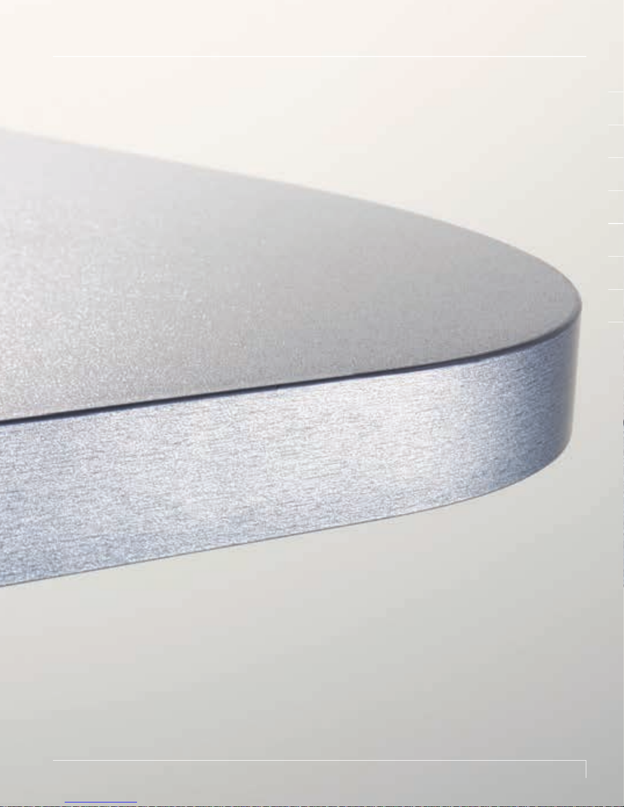
The perfect edge.
User manual for the CONTURO system.
Page 2

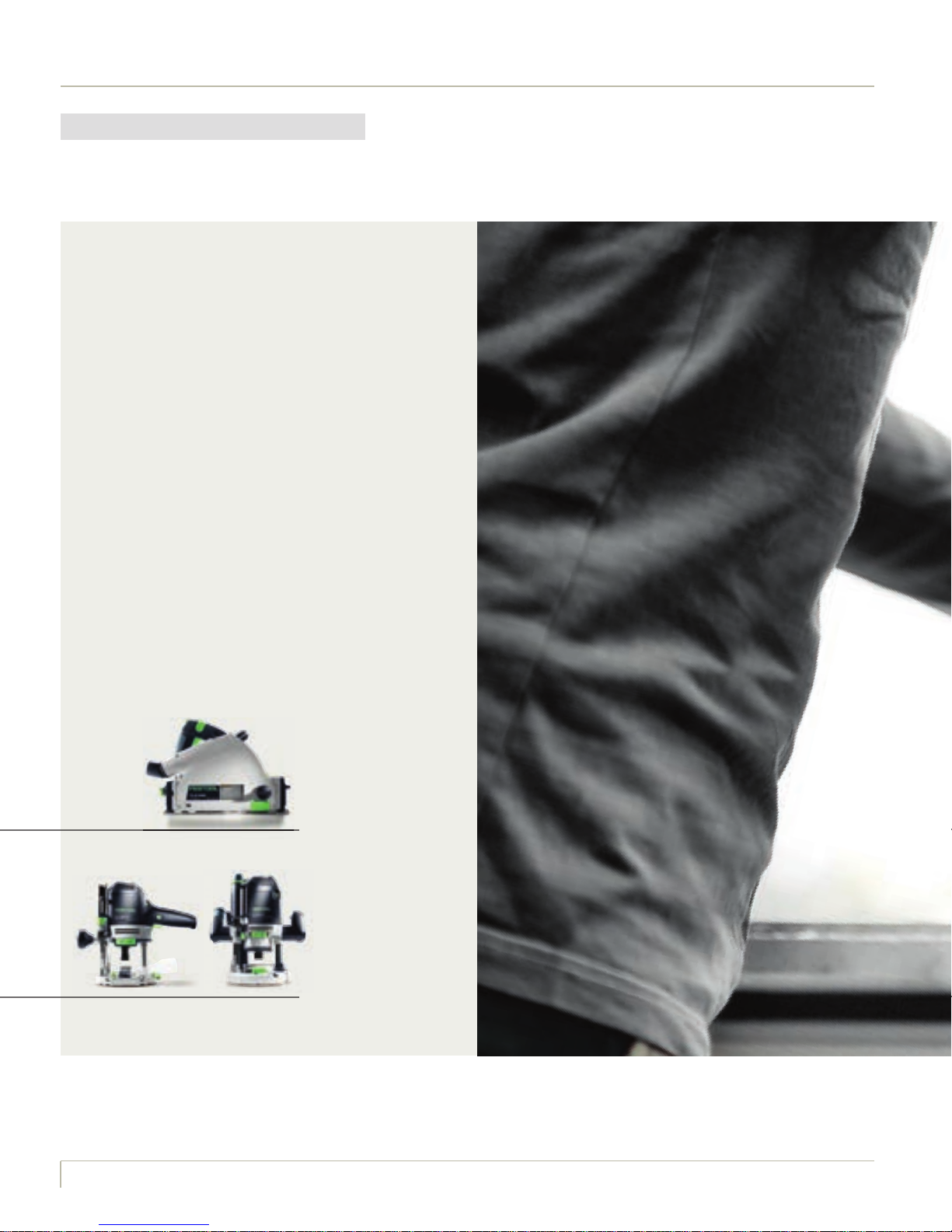
Introducing Wolfgang Reines.
Carpenter. Product manager. Inventor.
I always have mixed feelings when visiting
a carpenter‘s workshop. On the one hand,
I enjoy the smell of fresh timber and recognise the typical whirring and screeching of
saws cutting through wood. I also revel in
the atmosphere that I became so familiar
with during my training as a carpenter. But
then I immediately switch to my role as a
product manager, where I have to analyse
every working situation, every process and
even every individual action from a very
different perspective. I then arrange a
meeting with the cabinetmaker to discover
more about the processes in the workshop.
Or hold discussions with staff to gather
valuable information on how to achieve
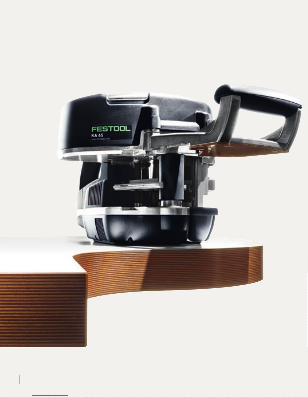
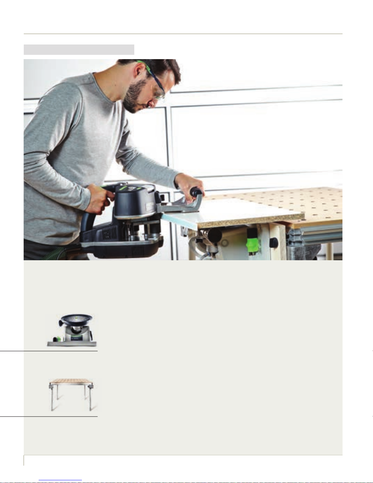
This is exactly how “The perfect edge” concept
was developed. As a central hand-guided
electric power tool for professional edge
banding, the CONTURO was not designed as
a replacement for stationary edging machines,
but rather as an effective system solution
for the manufacture of small batches or
rapid production of high-quality edging,
even on curved, convex or concave shapes.
One system that represents excellent
results and is easy to operate, but above all,
opens up new possibilities for fulfilling the
individual wishes of your customers.
the desired result more quickly. Which, for
example, could help prevent damage to
the material. I also try to obtain ideas that
could help achieve an overall better working
result.
Page 3

Page 4

Contents
PAGE
1 The perfect edge. The CONTURO in a system.
2 Basic information about CONTURO
3 Achieving the perfect edge
3.1 Preparing the workpiece 20
3.2 Preparing the machine and edge
Preparing the machine
Display information
Selecting and cutting edging to the correct length
Adjusting the edge height
3.3 Mobile gluing of edges
Mobile gluing and flush trimming of straight edges
Mobile attachment of edging to shaped parts with curves
Attaching long strips of edging
Mobile attachment of edging to round panels and manufacturing the perfect joint
Attachment of edging to internal corners
10
14
18
22
22
23
24
25
26
27
29
31
33
38
3.4 Stationary gluing of edges
Stationary gluing of straight edges
Stationary attachment of edging to mitred workpieces
Stationary attachment of edging to small shaped parts
3.5 Edge finish
Routing and smoothing edges flush, trimming overhanging material
Characteristics of routing mitred edges
Corner finishing
Cleaning edges
Sanding and polishing edges
High-gloss edging
40
42
44
45
46
47
48
49
49
50
53
Page 5

PAGE
4 Information on edging
5 Information about glue application
The CONTURO glue application system
The correct temperature
The perfect glue supply in line with the material
Refilling glue
Changing colours
6 Tips and tricks
Workstation VAC SYS design plan
Adaptation of VAC SYS to the MFT
Working with dust extraction
7 Items included, technical data
CONTURO
CONTURO accessories
Working with the CONTURO as a stationary unit
Edge router MFK 700 Basic
Edge router accessories
Supplementary system accessories – VAC SYS
Supplementary system accessories – MFT
54
58
61
61
61
62
63
66
68
72
73
74
76
77
79
80
80
81
82
54
Page 6
6
A beautiful finishing touch.
Edges on tables, cabinets and office equipment are just as important
as the workpiece itself, because if the finish is not perfect, it affects the overall quality of the
workpiece. The glued join may be visible, and dirt can accumulate. In the worst case scenario, it
work hand in hand. Continue reading this manual for more information.
Page 7
76
Page 8
Page 9

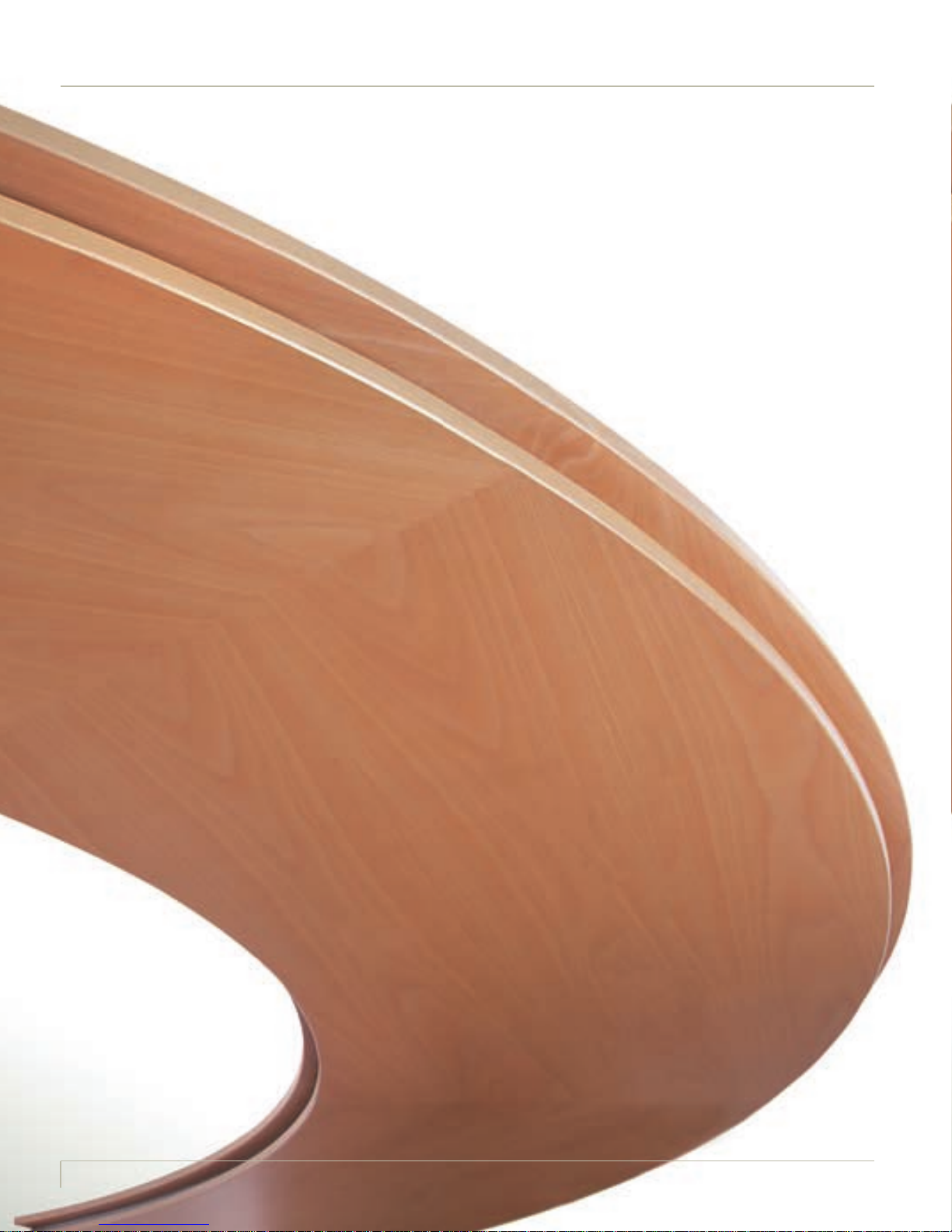
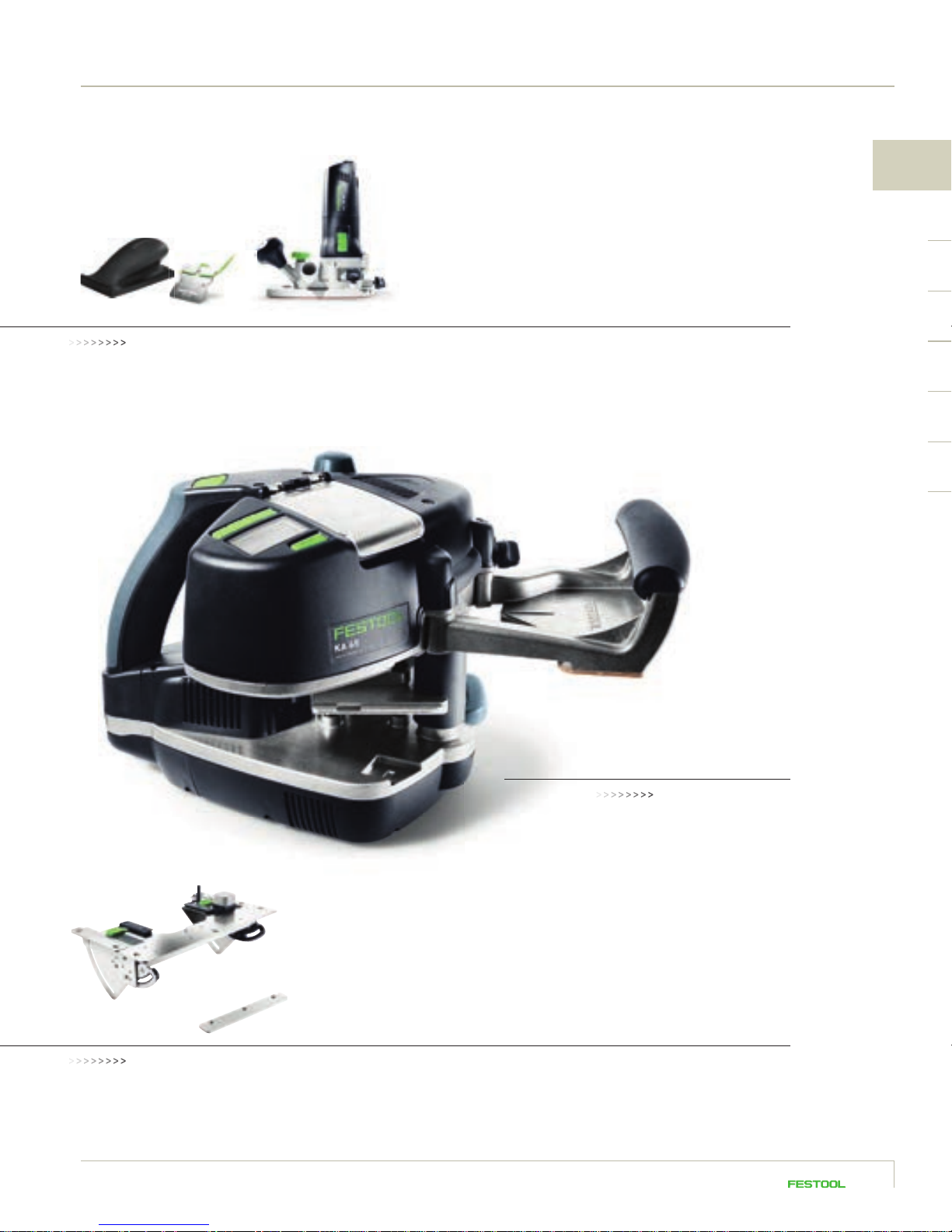
Versatile and easy to operate, the CONTURO represents a genuine solution for manufacturing
9
Page 10
Page 11

1
11
Page 12

WORKING WITH MFT WORKING WITH THE VAC SYS PREPARING THE WORKPIECE
1. The perfect edge.The CONTURO in a system.
At the heart of the system, the CONTURO is responsible for the gluing process while
the surrounding system components perform all other working steps. From cutting
and milling chipboard to size or applying glue, pressing down edging, cutting and
flush trimming, smoothing and polishing – the Festool system operates with a level of
professionalism and clean quality that only bench-mounted machines can achieve.
GLUES SPECIAL ACCESSORIESTRIMMING EDGING
12
Page 13
PERFECT EDGE FINISH
1
SySTem
STATIONARY TASKS
CONTURO
GLUING EDGING
ACCeSSORieS
13
Page 14
Page 15

2
15
Page 16
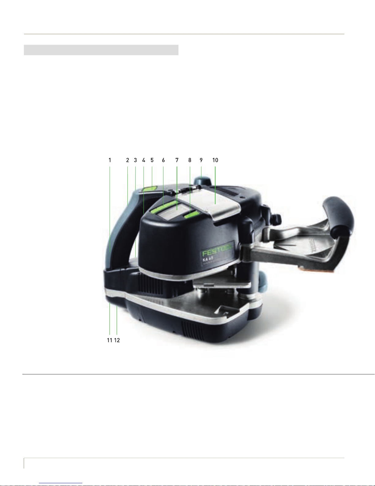
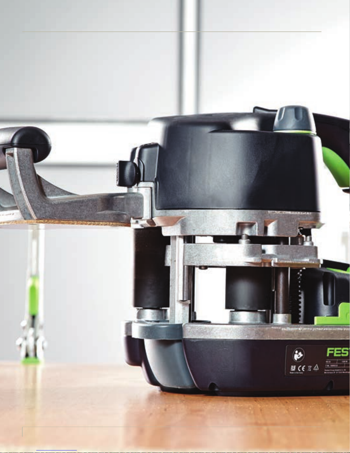
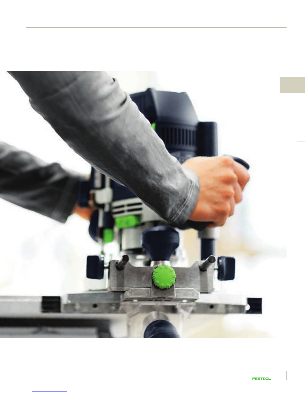
2. Basic information about CONTURO
Of all the ingenious details that the CONTURO has to offer, one stands out from the rest: unbeatable ergonomics. The horizontal mounted application system guarantees perfect weight distribution, while the pressure on
the handles is transferred to the contact roller automatically – for effortless working progress. Force is transferred irrespective of the edging height, as the machine is guided securely along the top of the workpiece.
This also makes it easier to adjust the edging height and provides a better view of the glued edge through the
support base.
1 HANDLE
2 TEMPERATURE SELECTION
3 ON/OFF SWITCH
4 FEED SPEED
16
5 START BUTTON
6 MENU BUTTONS
7 DISPLAY
8 REFILL BUTTON
9 EDGING HEIGHT SETTING
10 GLUE COMPARTMENT
11 EXTRACTOR CONNECTOR
12 MAINS CONNECTION
Page 17
2
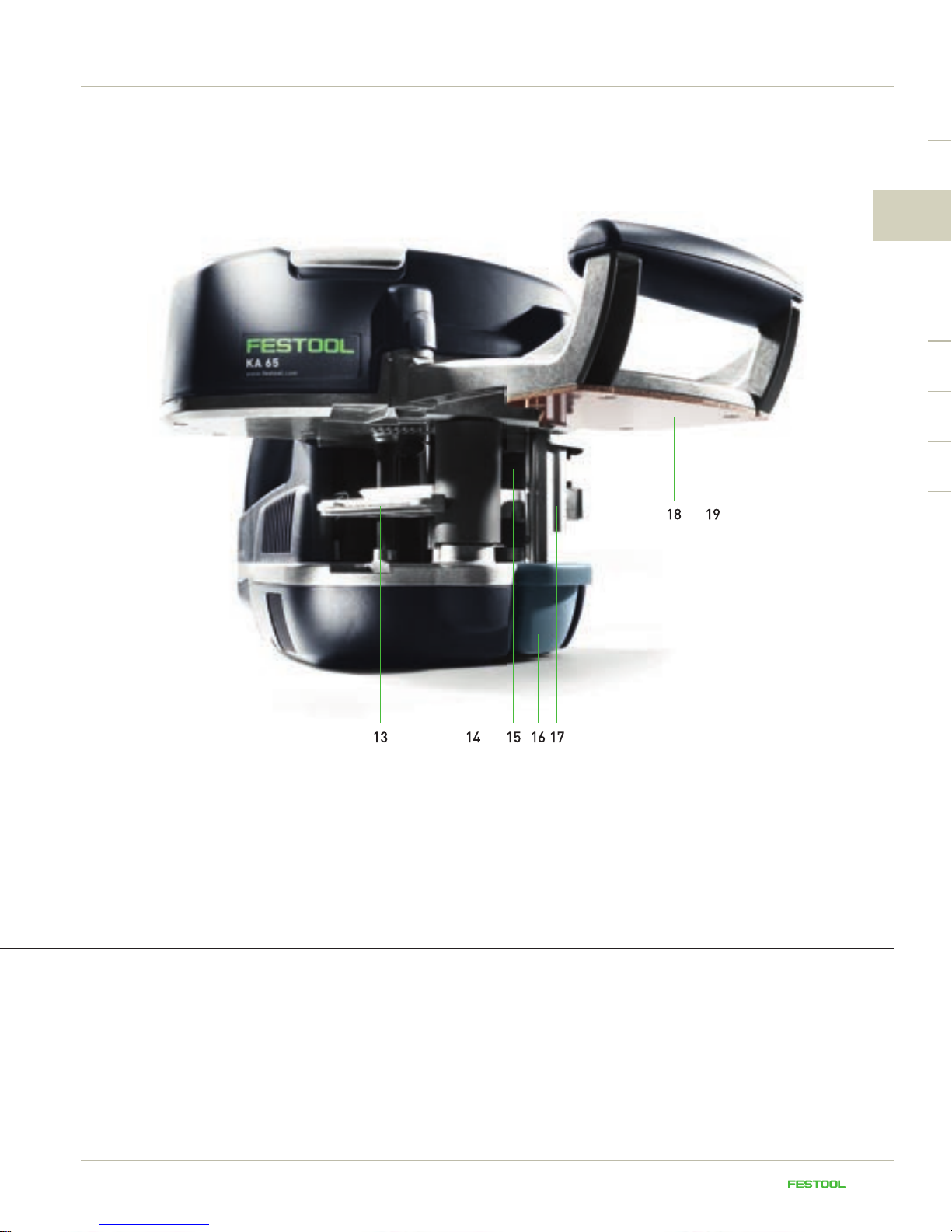
13 CENTRAL PLATE
14 CONTACT ROLLER
15 INFEED ROLLER
16 DRIP CATCHER
17 GLUE NOZZLE
18 SUPPORT BASE
19 HANDLE
17
Page 18

Page 19

3
19
Page 20
3.1 Preparing the workpiece
The respective workpiece must be prepared
correctly in order to achieve a perfect edge
finish. Several different options are available
here: cutting to size on a panel saw with a
scoring unit, or using a Festool plunge-cut saw
TS 55 R together with guide rail and splinterguard, or even cutting the edge with a Festool
router and guide rail. Whichever system you
choose, the workpiece should be 100 % clean
and splinter-free in preparation for subsequent
attachment of the edging.
PLUNGECUT SAW TS 55 R/
TS 75
ROUTER OF 1400/OF 2200
20
Page 21
3
21
Page 22

3.2 Preparing the machine and edge
A few settings must be configured before the CONTURO can be operated. The display on the machine
automatically guides you through the necessary steps.
Preparing the machine
1 2
Secure the support base first using the accompanying screw.
3 4
You can use the temperature preselection switch to adjust the
temperature according to the colour of the adhesive cartridge
selected.
Insert a minimum of two adhesive cartridges before using
for the first time.
CHANGING COLOURS Page 63
Changing colours, refilling, etc. Chapter 5
Now press and hold the ON button until the Festool logo
appears on the display.
CORRECT TEMPERATURE
Setting 1 = 190 °C for natural coloured adhesive
Setting 2 = 200 °C for white adhesive
Page 23
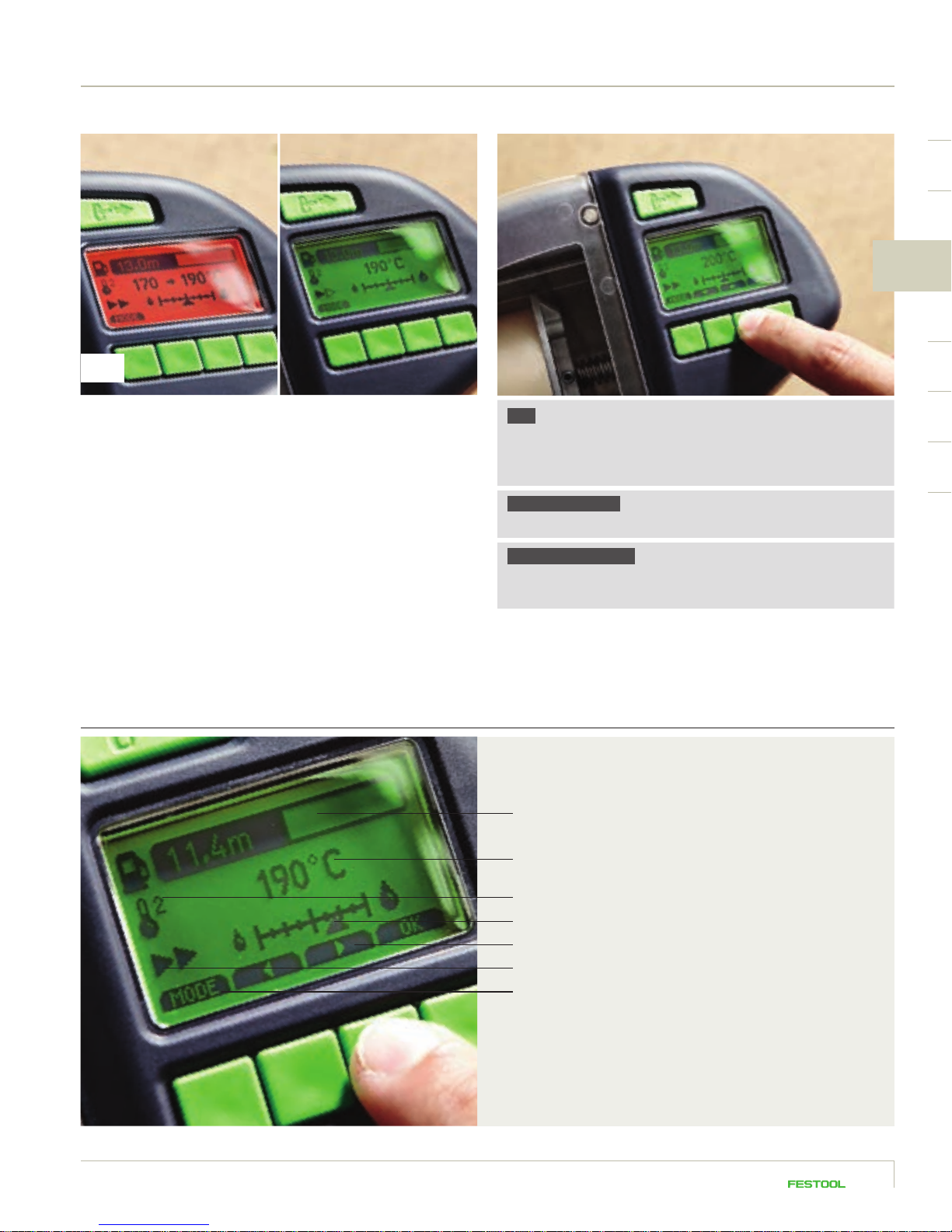
5
3
The machine heats up until the setpoint temperature is
reached. The heat-through phase then starts, which is indicated on the display. When the display changes from red to
green, the machine is ready for operation.
The CONTURO takes approximately eight minutes to fully heat
up. The thermally isolated gluing unit ensures that the surface
temperature of the machine remains low, thereby eliminating
any risk of burns.
Display information
TIP You can also adjust the temperature individually: press
the mode button until the temperature indicator flashes, set
the desired temperature using the arrow buttons and press
OK to confirm.
GLUE QUANTITY Page 61
For adapting the glue quantity Chapter 5
SWITCHING UNITS
The display can be switched from Celsius to Fahrenheit and
metres to feet.
REMAINING EDGE LENGTH
TEMPERATURE IN °C OR °F
TEMPERATURE SETTING
GLUE QUANTITY
ARROW BUTTONS
FEED SPEED
MODE
The display indicates how many metres of edging can
be processed at the preset edging height and glue
quantity. The actual temperature is also displayed.
2322
Page 24

Selecting and cutting edging to the correct length
1 12 2
Select the edging height according to the thickness of the
prepared panel material and include an overhang of approx.
4 mm.
You should add approx. 10 cm to the length of the edging.
EDGING OVER 1.5 M IN LENGTH Page 31
If the edging is longer than 1.5 m, it is more convenient
to work with the edging holder.
3 34 4
Simply score the edge band (plastic side) with a knife to
ensure a clean separating cut.
It is then easy to break off.
Page 25
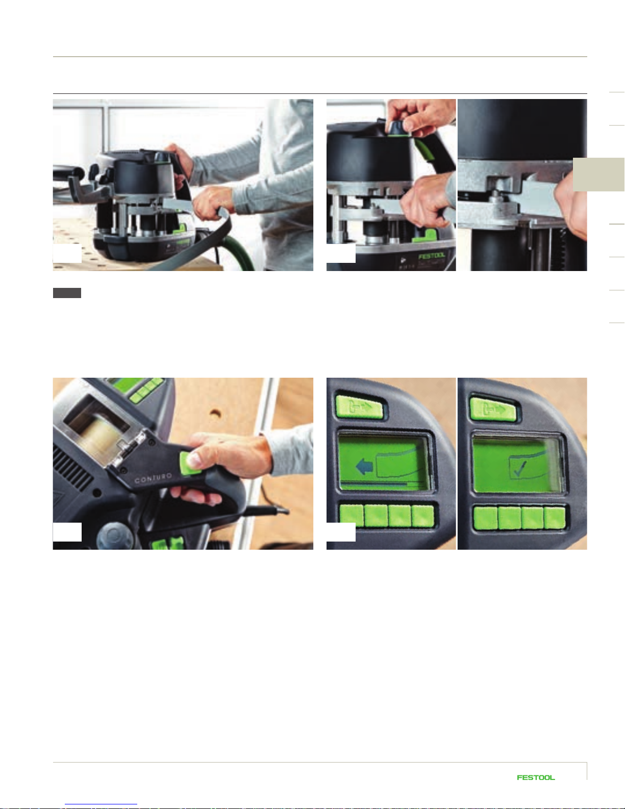
Adjusting the edging height
3
Slide the edge band into the edging infeed.
NOTE Note that the edging height can only be adjusted at
operating temperature.
Briefly press the start button. When the symbol for inserting the edging appears, guide the
Use the rotary knob to adjust the edging height until the
edge band touches at the top and bottom. Then turn back
the switch 1–2 locking positions so that there is some play
in the edge band.
edging into the active infeed until it is drawn in. When the tick
mark appears on the display, the edging has reached starting
position and the machine is ready for gluing.
2524
Page 26
3.3 Mobile gluing of edges
VAC SYS
MFT
The CONTURO is now ready to start fixing the edging to the workpiece. The most important thing is that the workpiece is clamped
securely. You can work on the Festool multifunction table MFT/3
either with screw or lever clamps, or use the Festool VAC SYS vacuum
clamping system or a combination of both. The VAC SYS system
was used in our example because the workpiece is accessible from
all sides – ideal for fixing edging to round workpieces.
Refer to the chapter “Tips and tricks” for further information on working with
the VAC SYS and MFT/3 as well as a plan of a workstation. Page 66
26
Page 27

Mobile gluing of straight edges
1 2
3
Position the CONTURO with the edging inserted and the
support base resting on the workpiece. Maintain a distance
of approx. 2 cm between the workpiece and contact roller.
The machine must be aligned at a 90° angle to the panel edge.
The marking line is located at the leading edge of the panel.
Press the start button again. The edging is automatically
coated with glue and fed along the workpiece. The machine
now operates automatically without the user having to hold
the start button pressed down.
3 4
As soon as the edging becomes visible to the right of the
mark, start the gluing process by guiding the machine along
the edge of the workpiece. The machine then feeds the edging
automatically, all you have to do is guide the machine while
applying constant pressure.
You have the option of selecting one of two speed settings.
You can change the speed at any time, even during the gluing
process. Simply press the button for the feed speed momentarily to increase or decrease the speed of the machine. This
function is extremely useful for attaching edging to tight curves.
27
Page 28

Mobile gluing (continued) and flush trimming of straight edges
5 6
Remove the machine from the end of the workpiece in the
edging direction.
NOTE Liquid glue on the end of the edging, for example,
can be extremely hot.
7 8
The tabletop on either side of the trimming machine allows
you to trim left and right panel edges ergonomically to the
same standard.
TIP Allow the end of the edging to cool before trimming
and make sure the trimming blades are sharp to guarantee
a clean and accurate cut. You should replace blunt or damaged
trimming blades with new blades, which are available as
spare parts.
The overhanging edging is now trimmed with the Festool
trimming machine KP 65/2: insert the edge band between
the trimming blades, move the trimming machine up to the
stop pin, position parallel to the workpiece and press the
handles together.
The result: edging trimmed flush with extreme precision.
The KP 65/2 trimming machine is also suitable for trimming
edging with a height of 18 – 65 mm and a thickness of 0.5 – 2.0 mm.
Positioning the trimming handles in the trimming direction
makes it much easier to trim thicker edging.
ROUND PANELS Page 33
The KP 65/2 trimming machine can be converted to trim
joins with a few hand movements.
Page 29

Mobile attachment of edging to shaped parts with curves
The CONTURO can attach edging to curves with an inner radius of 50 mm and a minimum outer radius
of 25 – 30 mm. The thicker and more brittle the edging material is, the larger the radius must be. The
process for attaching edging to curves is essentially the same as attaching edging to straight workpieces.
However, there are some small differences that you should bear in mind.
3
1
The additional roller is a helpful accessory for narrow curves and awkward spots. It increases the bending radius of the edging
and offers an additional pressure point during attachment for better adhesion. To attach the additional roller, slide it into the
groove provided until it engages.
32
The additional roller helps during the attachment of edging
to tight outer curves by pressing down on the curved workpiece together with the other roller.
It is always advisable to process narrow internal curves with
the additional roller.
TIGHT CURVES When affixing edging to tight internal or
external curves, set the feed speed to the 1st setting before
starting work or during the task by pressing the feed speed
button.
2928
Page 30

Mobile attachment of edging to shaped parts with curves (continued)
4
Like the process for attaching straight edging, trim the overhanging end of the edging flush using the trimming machine.
It is also advisable to work with the additional roller when
attaching rigid or brittle edging. The edging has a larger
bending radius and does not break as easily.
TIP Instead of gluing one thick
piece of edging along narrow external
curves with wooden edges, simply
glue several thin layers of veneer on
top of one another.
Page 31

Attaching long strips of edging
With edge bands longer than 150 cm, there is a risk that the edging will drag on the floor and become
soiled or stuck. The edging holder (accessory) was designed to avoid this situation. The edging is rolled
up neatly in the holder to guarantee an even feed into the machine. As a result, you can process up to
*
8 m of edging
* Depending on the relevant edge band material (measurements: height 18 – 45 mm, thickness 0.5 – 2.0 mm).
both quickly and easily.
3
1 2
Mount the edging holder first of all. Simply attach to the
pins provided and secure with the locking mechanism.
Place the roll of edging in the holder, positioning the end
of the edging in the direction of the edging infeed on the
machine.
You must cut the edging to length first and roll it up with the
visible side facing inwards because you cannot work directly
from the roll in the edging holder.
43
Start drawing the edging into the machine by pressing the
start button once. Thread the edging through the gap in the
edging holder and into the infeed. Gluing can begin as soon
as the machine draws in the edging.
3130
Page 32

Attaching long strips of edging (continued)
5
Now apply the edging to the workpiece in the usual way.
6
The edging is fed accurately to the workpiece from the edging
holder.
NOTE Edging with larger dimensions can be also fed into
the machine from the edging holder.
32
Page 33

Mobile attachment of edging to round panels
The greatest challenge when affixing edging to round panels is creating a clean join at the point where
one end of the edging meets the other. The Festool trimming machine is also extremely practical in this
regard.
3
When attaching edging to circular panels, it is important that
the workpiece can be accessed from all sides without having
to change the clamping position. We recommend using the
VAC SYS vacuum clamping system, which can secure the
workpieces quickly and safely, rotate them 360° and tilt them
up to 90°.
Pads of different shapes and sizes are available for a wide
range of workpieces and can be changed without using tools.
They are manufactured from high-quality plastic which is so
soft and flexible that even high-gloss polished surfaces remain
free of scratches and damage.
21
When cutting the edge band to size, make sure that you add
approx. 10 cm to the overall band length. Trim the leading end
of the edging exactly perpendicular because it forms part of
the join.
Glue the edge in the usual way. The edging holder is a practical
accessory that offers maximum freedom of movement and
protection of the edging.
33
Page 34

Page 35

Mobile attachment of edging to round panels (continued) and manufacturing the perfect joint
3 4
3
Make sure that the overhanging end of the edge band does
not come into contact with the other end that has already
been glued.
5 6
NOTE If you wish to hold the edging, remember that the
glue is still hot.
TIP If the edging material is particularly delicate, protect
the front end with adhesive tape to prevent any contact with
glue.
Set the trimming machine to the “Join” configuration.
ADJUSTING SETTINGS FOR BUTT JOINTS
Setting the trimming machine see operating manual
3534
Page 36

Manufacturing the perfect join (continued)
7 118 12
Mark the cutting point on the edge band. Guide the overhanging end of the edge band over the stop pin
between the trimming blades. Push the trimming machine
forwards towards the workpiece up to the stop pin until the
edge band that has already been glued, rests against the inner
stop.
9
Position the trimming machine so that the marking on the
edge band is located in between the trimming blades. Then
use the fine adjustment feature to adjust the blades more
accurately: the scale indicates whether you have to cut more
or less from the edge band. Once the mark is located exactly
between the two trimming blades, trim the piece of edging.
TIP Before trimming, push the trimming blades together
to achieve better alignment.
10
After trimming, use a hot air blower to heat the edge band
with glue already applied.
NOTE Plastic edging stretches when heated and may have
to be trimmed slightly more. The best approach is to test the
actual edging material.
Page 37

3
Complete the join by pressing down the edge band with a block
of wood.
TIP If you intend to manufacture several identical work-
pieces, you can continue working with the value preset on
the trimming machine without making any markings.
13
The result: the perfect join.
3736
Page 38

Attachment of edging to inner corners
Inner corners of 90° are usually found on corner cabinets and shelves, which incorporate compartment
or carcass bases. Edging these panels is challenging because the inner corners must be glued.
1 2
Ensure you clean and trim the leading end of the edging
perfectly perpendicular, as it forms part of the join.
As soon as the end of the edging is positioned precisely in the
inner corner, guide the machine out of the corner with an even
pressure. At the same time, press down the end of the edging
in the inner corner with the thumb on your right hand to
achieve maximum adhesion.
Place the CONTURO on the workpiece in the usual way and
position the machine on the inner corner. Press the start button
to feed the edging automatically.
NOTE Always work with the additional roller!
43
Always work with the slowest feed speed when affixing edging
to inner corners (speed 1).
TIP If the edging is longer, it may make sense to engage
the help of another person to generate the required contact
pressure on the inner corner.
38
Page 39

3
5
Turn the panel so the inner corner is located on the right hand side of the machine. The machine can then be guided from left to
the right, along the side that has no edging.
39
Page 40

3.4 Stationary gluing of edges
You can also work with the CONTURO as a stationary unit.
Simply insert an adapter plate in the MFT/3 multifunction table or a bench you have built yourself.
Not only can you affix edging to straight edges or curves, but also oblique edges with an angle
between 90° – 45° because the CONTURO can be tilted 90°– 45° in the stationary unit.
1
If you intend to use the CONTURO in the MFT/3, first replace the perforated board with panel LP-KA 65 MFT/3. The recess in the
panel is the right size for installing the adapter plate and the threaded bushes for the guide plates.
If you are working with a bench you have built yourself, the tabletop will require a recess and a cut-out so that the adapter plate
can be screwed in flush. Refer to the accompanying routing template for the exact dimensions.
Page 41

2 3
3
Then mount the adapter plate and guide plates as described
in the operating manual. The guide plates make it easier to
guide the workpiece over the bench. 15 guide plates are
delivered with the adapter plate as standard but additional
guide plates are available as accessories.
TIP The hole spacing on the guide plates is designed for
system 32, which makes it easier to manufacture individual
worktops. You can also screw on guide plates without
threaded bushes using normal wood screws.
Insert the CONTURO in the adapter plate as follows: first tilt
the adapter plate upwards and lock in position.
4 5
Then release the lock on the right and left of the panel, slide
the CONTURO into position and lock again.
Now set the required angle on the scale and lock both
clamping screws. Your stationary unit is now ready.
4140
Page 42

Stationary gluing of straight edges
To glue onto straight edges, place the CONTURO in a horizontal position and guide the workpiece past it.
This working method is very practical for small or narrow workpieces that are difficult to clamp.
1 2
Set edging height with some play so that the edging slides
smoothly through the machine.
Ensure the correct speed is selected before you begin the
gluing process, as both of your hands will be placed on the
workpiece.
Then press the start button and guide the machine towards
the edge.
43 6
Position the workpiece at a distance of 2 cm from the contact
roller and press the start button again.
Page 43

5
As soon as the glued edging becomes visible, press the workpiece against the contact roller.
3
6
Guide the workpiece along the contact roller while applying
even pressure.
TIP When processing rigid or brittle edging in the stationary
unit, it is also advisable to work with the additional roller
(included with the adapter plate). Screw on the additional
roller and guide the workpiece along it at a slight angle. The
edging has a larger bending radius and does not break as
easily.
The additional roller can be used for applications such as
tight inner and outer curves or mobile applications – both
rollers press down the edging and the extended pressure
zone achieves better adhesion.
4342
Page 44

Stationary attachment of edging to mitred workpieces
Simply tilt the CONTURO in the stationary unit to affix edging to a mitred edge. The scale indicates the angle
in degrees.
1 52 6
Loosen both clamping screws on the angle scale, set the
desired angle and tighten the clamping screws again.
Use the guide rail adapter to ensure the workpiece is guided
parallel and prevent the edging from running off course. Adjust
the guide rail adapter to the thickness of the edging you are
using. Available thickness settings are 0.5, 1, 2 and 3 mm.
Adjust the edging height in the usual way.
TIP Edging for mitred edges requires a slightly larger over-
hang. For example, edging 35 mm high is used on a 19 mm
panel with a 45° edge.
43
Select the desired speed before starting the gluing process
as you will always need both hands on the workpiece when
gluing.
Page 45

3
Place the workpiece on the guide rail adapter and guide evenly
past the CONTURO. Loop the edging over the black guide pin
so that it does not obstruct the working area.
Your mitred edge is quick and easy to glue.
Stationary attachment of edging to small shaped parts
In order to attach edging to shaped parts, you may have to partially unscrew the guide plates otherwise they
could prevent you from turning and guiding the workpiece along the CONTURO, depending on the shape.
The edging is glued as already described.
TIP If you have to unscrew all the guide plates, simply attach
them to the underside of the shaped part using double-sided
adhesive tape. This ensures the part is at the correct height
in relation to the edge bander or edge band, and also that
the correct amount of edging is overhanging.
4544
Page 46

3.5 Edge finish
MFK 700 EDGE ROUTER
Once the edging is glued and trimmed, add the finishing touches: cut
away overhanging material, smooth edging, finish corners and polish
edging to a high gloss finish if necessary.
Ideal for routing edging: the Festool MFK 700 Basic edge router with
spring-loaded ball bearing guide brake and chip deflector. This is
designed specially for machining the most delicate of edging without
leaving behind marks.
The scraper is made from durable solid carbide and was specially
designed for smoothing edges. The scraper has three integral edges
(R1, R1.5 and R2 mm) for smoothing routed curves and rounding thin
edging.
SCRAPER
46
Resting the scraper on the attached
cord ensures perfect guidance.
The three different edges on the scraper
allow you not only to smooth down
edging, but also round thin edging.
Page 47

Routing and smoothing edges flush, trimming overhanging material
1 2
First trim the overhang from the edging using the MFK 700 so that it is flush with the panel. Practical: the extractor hose is
attached directly at the tabletop and does not pose an obstacle when guiding the machine. The ball bearing guide brake ensures
perfect, streak-free working results.
3
3
To achieve a clean, rounded finish, move the edge router
towards the edging with the cutter rotating and trim the
overhang as well as the radius.
5
If the cutter leaves impact marks during the routing process,
you can smooth them over using the scraper.
4
You can remove any remaining overhang using the scraper.
NOTE Special classic ogee cutters with reversible blades
are available for the MFK 700 Basic with radii of 1, 1.5, 2 and
3 mm. Suitable for edging thicknesses of 1, 1.5, 2 and 3 mm.
47
Page 48

Characteristics of routing mitred edges
Please note that a radius cannot be created due to the angle and only flush milling of mitred edges is possible.
The S8 HW OFK plane cutter for the MFK 700 Basic was specially developed for milling 0° – 45° edges.
1 2
First install the router cutter in the MFK 700 Basic. Then mill the workpiece flush.
3
Make sure that the extraction hood under the machine is
resting directly against the workpiece as this can be used as
a guide. Then create the radius on the wooden edge using
sandpaper.
TIP Use one of the edges on the scraper to smooth the ra-
dius on plastic edging. Use the straight edge on the scraper
to smooth and round off the flat inner angle. Draw the
scraper over the edge several times until the radius or curve
is perfect.
S8 HW OFK plane cutter for routing 90° – 45° edges.
Page 49

Corner finish
Cleaning the corners is particularly
important. If the edge is routed and
not reworked, a slight overhang
usually remains, which must be
removed. We recommend you use
Festool Brilliant 2 sandpaper, with
P320 grit to remove any significant
unevenness.
Using a sanding cloth after this
will help produce a semi-matt
finish which is smooth and even.
3
Cleaning edges
Once the radius on the edge is
perfect, the edge should be
cleaned. Use a plastic cleaner
– edging manufacturers will recommend a compatible cleaner.
4948
Page 50

Sanding and polishing edges
If the result achieved with the scraper is not sufficient, you can always sand and polish the edge. Festool also
offers suitable system accessories here – for a finish adapted perfectly to the edging.
1
First attach the correct abrasive with a P320 grit to the hand sanding block.
32
You can eliminate cutter impact marks left behind after milling
by simply sanding the edge. Repeatedly move the hand sanding
block lightly over the edge in a steady motion to achieve this.
NOTE Do not sand the surface of plastic-coated panels!
The appearance of plastic edging changes when processed and
often turns white. Attach a sanding cloth to the hand sanding
block and rework the edge to match the colour with the decor
again. The cloth produces a semi-matt finish on plastic edging
and the surface of the edge blends in with most decorative finishes.
Page 51

4 5
3
Right of image: stress whitening from sanding plastic edging.
Left of image: edging without stress whitening, reworked with
cloth.
6
Dab a small amount of MPA 6000 polish onto the polishing felt
and rub over the surface.
High-gloss surfaces can also be polished. Attach the polishing
felt to the hand sanding block.
7
Polish the edge …
8
… and remove any polish residues.
TIP Stress whitening is generated when edging is trimmed.
You can remove the whitening simply by rubbing an offcut of
edging over the affected area while applying slight pressure.
5150
Page 52

Sanding and polishing edges (continued)
9
The result: the perfect edge.
Page 53

High-gloss edging
When working with the CONTURO, dust or foreign matter on the surface of the panel may leave scratches
on particularly delicate surfaces. We reccomend you use the scratch protector with felt pad available as an
accessory from Festool, to prevent any damage.
1 2
3
Change the base runner on the underside of the support base
by removing the four screws. Then secure the guide plate on
the LAS-STF-KA 65 scratch protector, which has a Velcro
fastener underneath.
Secure a felt pad to the protector to guarantee ease of
movement over the workpiece.
NOTE The scratch protector includes 3 felt pads,
replacement felt pads are available separately in packs of 10.
43
The surface is protected … … and remains free of scratches.
5352
Page 54

Page 55

4
55
Page 56

4. Information on edging
The CONTURO is capable of processing a wide range of different
edging materials. We recommend using the additional roller
when processing thick or brittle edging. The roller helps process
rigid, thick veneered edging more easily.
More information on the additional roller
The CONTURO can affix edging with a height of 18 – 65 mm and
a thickness of 0.5 – 3.0 mm. Use of the edging holder restricts
the maximum edging height to 45 mm and the maximum edging
thickness to 2.0 mm.
The values for particularly brittle or thick edging, or edging with
extreme interior / exterior curves, may deviate from the values
mentioned above. Carrying out tests is the best way to ensure
the correct value.
Page 29
Edging thickness 0.5–3 mm Edging height 18–65 mm
Page 57

4
5756
Page 58

Page 59

5
59
Page 60

5. Information on glue application
The Festool unique glue application system on
the CONTURO, offers a host of benefits. For
example, the heating grid only melts the exact
amount of glue required. This prevents heating
glue unnecessarily and retains the adhesive
properties and colour of the glue to ensure
consistently good results. One other advantage
of this technology is that heat requirements and
energy consumption are low during operation.
The system for supplying glue from the glue
cartridges is also extremely simple, clean and
convenient.
Easy, clean and efficient working progress and unique
cartridge gluing system for quick colour changes.
60
Glue applied to edging
Page 61

The glue application system on the CONTURO
The glue is applied to the edge band through a nozzle for greater precision, guaranteed clean edges
and narrow joins. The glue dosage is adapted automatically to the preset edging height. The “remaining
edge length” indicator on the display shows how many metres of edging can be affixed with the current
settings. Additionally, you always know whether you need to insert additional glue cartridges, which is
important because it is not possible to insert cartridges during the gluing process.
The correct temperature
The CONTURO has two temperature settings:
Setting 1 = 190 °C for natural coloured glue
Setting 2 = 200 °C for white glue
The perfect glue supply in line with the material
When applying glue to porous materials such as chipboard, it is advisable to increase the flow of glue. Simply
press the mode button in the display menu until the value you wish to change flashes. Use the arrow buttons
to change the value and press OK to confirm. The remaining edge length is recalculated automatically in line
with the new preset glue quantity.
5
61
Page 62

Refilling glue
If the petrol pump symbol appears on the display or there is not enough glue to affix the edging, refill the
machine as follows before starting the next gluing process:
1 12 2
Press the refill button and wait until the glue feed has moved
back. The display now indicates that the machine is in refill
mode. Wait until the hourglass symbol has disappeared before
opening the flap.
Place the new glue cartridges (of the same colour) into the
magazine.
Lift the flap as soon as the open symbol appears.
4 43 3
Close the flap again and wait until the glue feed moves forward
and exerts pressure on the cartridges. The refill process is now
complete and you can continue working with the CONTURO.
Page 63

Changing colours
Festool offers glue cartridges in the colours white and natural. The white glue is mainly suitable for producing virtually invisible joins on bright and white materials, whereas the natural coloured glue is ideal for all
types of wood and other colours. If you wish to change the colour of the glue, the glue with the old colour can
be pressed from the machine without an edge band, as described here.
5
The CONTURO system contains approximately the same
quantity of glue as three glue cartridges. You must therefore
use three cartridges to purge the machine completely.
Now press the refill button, …
Place the machine on the edge of the bench for purging and
remove the drop catcher.
Position a container (e.g. box) under the CONTURO to catch
the hot glue.
… wait until the feed has moved back and open the flap. If you
can see full cartridges with the old colour in the machine,
these can now be removed.
6362
Page 64

Changing colours, continued.
65
Insert new adhesive cartridges in the desired colour and close
the flap again.
7
Actuate the safety lever for purging the machine while
simultaneously turning the rotary knob clockwise until the
central plate rests against the bottom of the machine.
The machine now is set to purging position.
NOTE Glue may escape immediately.
Adjust the rotary knob to the maximum edging height.
8
Press and hold the start button until the purging symbol
appears on the display. Glue now starts to escape from the
nozzle.
9
Allow purging to continue until the new colour escapes from
the nozzle. You may have to repeat steps 3 – 8 to insert additional
cartridges.
You can finish or interrupt purging by pressing the start button
again and turning the rotary knob clockwise until the desired
edging height is set. The glue nozzles are then closed again,
the display indicates that the machine is ready for normal
operation. Insert the drop catcher again at the end of the purging
process.
Page 65

Notes
5
6564
Page 66

Page 67

6
67
Page 68

6. Tips and tricks
Some components of the Festool system make working with the CONTURO even easier because all components
have been adapted perfectly to one another. Below are a few examples of how to make your daily work easier.
Plan for VAC SYS workstation
When working with the CONTURO, the workpiece must be secured firmly before any edging can be affixed.
And round workpieces that cannot be clamped from edge to edge must be accessible from all sides.
Many tasks described in this manual were therefore performed with a Festool VAC SYS vacuum clamping
system adapted perfectly to the correct working height of the CONTURO. You can find the plan for this
workstation and other tips here.
1 2 3
Page 69

6
6968
Page 70

365
380
320
70
60
97
Plan for VAC SYS workstation
FRONT VIEW
500
TOTAL HEIGHT
You can individually adjust the
overall height to your body height
and the desired working height.
This plan gives a working height
of 90 cm (including the VAC SYS).
640
540
400
1250
BASE PANEL
The workstation is secured to a square base panel, 1,250 x 1,250 mm.
Page 71

355
365
320
380 380
320
70
6050
97
215
140
365
380
320
70
60
97
LEFT SIDE VIEW
with recess for compressed air hose,
control elements and plug-it cable
RIGHT SIDE VIEW
with recess for pump ventilation
380
320
215
140
50
355
60
380
6
320
70
97
365
7170
Page 72

Attaching the VAC SYS to the MFT
The multifunction table MFT/3 provides another option for working with the VAC SYS. Since the working
height of a VAC SYS mounted on the MFT is too high for most users working with the CONTURO, we
recommend the following adaptation:
500
12
Ø 0,6
Ø 0,6
Ø 0,6
60
Ø 0,6
193
250
87,5 87,5
Ø 0,6
For example, use a birch multiplex panel with a thickness of
23 mm (500 mm x 250 mm). Drill holes with a diameter of
6 mm according to the drawing. The VAC SYS is secured with
4 x M5 60 mm carriage bolts and 4 x M5 wing screws with
washers.
325
Ø 0,6
The board is secured to the MFT via the groove on the side
profile of the MFT. Compatible keys and rotary knobs are
available from Festool as spare parts: 2 x 437377 key,
2 x 482110 rotary knob
72
Page 73

Working with dust extraction
6
When working with the CONTURO, you can extract any vapours with a Festool mobile dust extractor – which
makes tasks that take longer more pleasant. There is an extractor connector located behind the machine,
which can be attached to a Festool suction hose D 27.
All Festool mobile dust extractors are suitable for dust extraction. Vapours are discharged away from working
area, but remain within the room. The CT 17 mobile dust extractor also offers the possibility of connecting
a second suction hose to discharge the exhaust air outside.
73
Page 74

Page 75

7
75
Page 76

7. Items included, technical data
CONTURO KA 65 Items included Technical data
Edge bander KA 65 Plus
Edge bander, complete with guide table, 4x natural EVA adhesive,
in a SYSTAINER SYS 4 T-LOC
Edge bander KA 65 Set
Edge bander, complete with guide table, 4x natural EVA adhesive,
in a SYSTAINER SYS 4 T-LOC and edge trimming set SYS KB-KA 65,
in a SYSTAINER SYS 4 T-LOC
Edge trimming set SYS KB-KA 65
Edging holder, additional roller, trimming machine, scraper, base runner
scratch protector with 3x felt pad, 5x polishing felt, 20x abrasive sheets
StickFix Brilliant 2 80x133 mm P320, hand sanding block 80x133 mm,
5x StickFix sanding cloth S 800, polish MPA 6000
Edge bander KA 65
Power 1,200 W
Mains frequency 50/60 Hz
Edging height 18 - 65 mm*
Edge thickness 0.5 - 3.0 mm*
Inner radius > 50 mm*
Heating time approx. 8 min
Melting temperature
Default setting
Melting temperature
Setting range
Feed speed 1st gear 2 m/min
Safety class 1
Weight
(without glue cartridges and mains cable)
* Depending on material
Setting 1 190 °C
Setting 2 200 °C
Setting 1/2 100 – 210 °C
2nd gear 4 m/min
7.9 kg
76
Page 77

CONTURO KA 65 Accessories
Polishing felt PF-STF 80x133 STF H/5
5x polishing felt StickFix, 80 x 133 mm
X For polishing high-gloss edging in combination with polish MPA 6000
and hand sanding block HSK x 80 x 133
EVA adhesive, EVA nat 48x-KA 65
48x natural EVA adhesive, diameter 63 mm, height 26 mm,
processing temperature 190 °C
X Affixing wooden, plastic or laminated plastic edging to panel materials
X EVA universal adhesive with high melting point, also suitable for use on objects
with a higher resistance to temperatures
X Natural colour tone suitable for all types of decor
The adhesive is delivered
in boxes of 48.
EVA adhesive, EVA white 48x-K A65
48x white EVA adhesive, diameter 63 mm, height 26 mm,
processing temperature 200 °C
X Affixing wooden, plastic or laminated plastic edging to panel materials
X EVA universal adhesive with high melting point, also suitable for use on objects
with a higher resistance to temperatures
X Perfect join quality on white decor
Scraper ZK HW 45/45
Dimensions 4.5 x 4.5 x 1.2 cm, with 1 mm, 1.5 mm and 2 mm radius
X Trimming overhanging material after the edge is cut (plastic edging)
without damaging the surface of the workpiece
X Smoothing away impact marks left by cutters during the routing process
(R1, R1.5 and R2 mm curves)
X Breaking edges, affixing curve and cleaning thin plastic edges and inclined
edges/mitred edges (R1, R1.5 and R2 mm curves)
X Scraper rested on the attached cord for perfect guidance
X Solid carbide for greater durability and resistance to wear
7
Additional roller ZR-KA 65
For use on thick or inflexible edges, offers a second pressure point
X Safe processing of thick and brittle veneered edges due to large bending radius
of the edge
X For affixing edging to tight cur ves and shaped parts
X Offers additional pressure point for applying more pressure on the edge of the
board when glued
77
Page 78

CONTURO KA 65 Accessories
Base runner scratch protector LAS-STF-KA 65
Base runner with fastener, 4 retaining screws, 3x felt pads.
X For using the edge bander on delicate or high-gloss surfaces
X With StickFix system for quick and easy replacement of the felt layer
Replacement felt EF-LA S-STF-KA 65 10x
10x replacement felt, for use with base runner scratch protector LAS-STF-KA 65
Edging holder KSP-KA 65
For feeding in long or delicate edging. For a maximum edging height of 45 mm,
maximum edging thickness 2 mm.
X For the safe guidance of delicate and thin edging into the edge bander K A 65
X Safe guidance of long edges without damaging or soiling
X Max. edge lengths of 8 m (edge thickness of 2mm) possible
X Easy machine guidance, even along long edges
Trimming machine KP 65/2
Trimming height 65 mm, trimming thickness 2 mm. For trimming on the right and left
side as well as circular edging.
X Join trimming function (for round table) and trimming of panel edges
(final trimming) with a single machine
X For trimming plastic edging with a height of 18–65 mm and a thickness of 0.5 – 2.0
mm (depending on material)
X Ergonomic handle location for easy, effortless trimming, even on thick edging
X Patented eccentric fine adjustment for precision join trimming
X Tabletop on both sides of the trimming machine allows the user to trim left and
right panel edges from above - with a perfect view of the workpiece
Page 79

CONTURO KA 65 Accessories for bench-mounted applications
Perforated board KA 65 LP-K A 65 MFT/3
Perforated board for stationar y use of the CONTURO in the MFT. For use in
combination with adapter plate AP-KA 65. Includes M4 reducing rings for
attaching guide plates.
X With cut-outs for stationary use of the edge bander in the MFT multifunction
table in combination with the adapter plate AP-KA 65
Adapter plate AP-KA 65
Adapter plate for using the CONTURO as a stationar y machine. Mounting plate
complete with 15 guide plates.
Length 254 mm, width 420 mm, swivel range: 0 – 47°
X For mounting the edge bander on a workbench
X For small batches, straight edges, free form elements and gluing inclined
edges, angle from 0 - 47°
X Adapter plate for installation in the MFT (with perforated board KA 65)
or a separate workbench
X Sliding guides for guiding the workpiece safely
X Allows the user to swivel the machine (0 - 47°) in the bench and position the
workpiece horizontally during edging - for convenient and safe guidance,
even with larger objects
7
Guide plate MFT GP-KA 65 MFT/3
15 guide plates, for guiding workpieces in stationary applications.
Length 255 mm, width 31 mm, height 6 mm
X Replacement or extension guide plates for the stationary use of the edge
bander with adapter plate AP-KA 65 in MFT (with perforated board K A 65)
or installed in a separate workbench
X Guide plates for attachment using chipboard screws or M4 screws included
with the delivery
7978
Page 80

Edge router MFK 700 Basic
Module edge router MFK 700 EQ/B-Plus 230-240V
Module edge router for machining overhanging edges, ball bearing guide brake,
in a carton
X Edge router specially designed for flush trimming and rounding protruding edges
X Unique ball bearing guide brake ensures perfect, streak-free working results
X Possible to flush trim 0 - 45° inclined edges (depending on cutter)
X Good view of the workpiece, extraction directly from the table
X Perfect working results with precision fine adjustment
X Large support base ensures safe guidance
Technical data
Power consumption 720 W
Idling speed 10,000–26,000 rpm
Collet dia. 6 - 8 mm
Fine routing depth adjustment 14 mm
Cutter diameter max. 32 mm
Dust extraction connector 27 mm
Weight 1.9 kg
MFK 700 Basic Accessories
Plane cutter
Plane cutter S8 HW OFK
Cutter for routing edges 90–45°
Diameter 28 mm, working length 7 mm, angle 15°, total length 40 mm
Classic ogee cutter with reversible blades
X Cutter for rounding wood and plastic edges as well as solid wooden workpieces
X Reversible carbide blade provides extreme precision, no resharpening required
X Extremely economical due to long useful life
X Reversible blades can be used 4 times and are easy to replace
Classic ogee cutter with reversible blades S8 HW R1 D28 KL12.7OFK
Diameter 28 mm, working length 1 mm, radius 1 mm, total length 55 mm
Classic ogee cutter with reversible blades S8 HW R1.5 D28 KL12.7OFK
Diameter 28 mm, working length 1.5 mm, radius 1.5 mm, total length 55 mm
Classic ogee cutter with reversible blades S8 HW R2 D28 KL12.7OFK
Diameter 28 mm, working length 2 mm, radius 2 mm, total length 55 mm
Classic ogee cutter with reversible blades S8 HW R3 D28 KL12.7OFK
Diameter 28 mm, working length 3 mm, radius 3 mm, total length 55 mm
Classic ogee cutter with reversible blades
80
Compatible replacement reversible blades are available for all classic ogee cutters.
Visit www.festool.com for more information
Page 81

Vacuum pump and clamping unit VAC SYS
VAC SYS Set SE 1
Vacuum pump VAC SYS VP in SYSTAINER SYS 3, vacuum clamping unit VAC SYS SE
1 with vacuum pad VAC SYS VT D 215 mm, vacuum hose and foot valve in
SYSTAINER SYS 4
VAC SYS SE 2
Vacuum pad VAC SYS VT 275 x 100 mm, connecting piece, vacuum hose,
in a SYSTAINER SYS 4
Technical data
Power consumption at 50 Hz 160 – 200 W
Power consumption at 60 Hz 200 – 230 W
Pump capacity at 50 Hz 2.7 m
Pump capacity at 60 Hz 3.5 m
Minimum vacuum ≥ 81% /≥ 810 mbar
Weight 8 kg
VAC SYS Accessories
Vacuum pad VAC SYS VT 200x60
for VAC SYS SE 1, VAC SYS SE 2, pad dimensions 200 x 60 mm, in a carton
3
/h
3
/h
7
Vacuum pad VAC SYS VT 275x100
for VAC SYS SE 1, VAC SYS SE 2, pad dimensions 275 x 100 mm, in a carton
Vacuum pad VAC SYS VT 277x32
for VAC SYS SE 1, VAC SYS SE 2, pad dimensions 277 x 32 mm, in a carton
Vacuum pad VAC SYS VT D 215
for VAC SYS SE 1, VAC SYS SE 2, diameter 215 mm, in a carton
Adapter VAC SYS AD MFT 3
for VAC SYS SE 1, VAC SYS SE 2, for connecting the VAC SYS clamping unit
with the MFT 3, in a carton
Accessories SYSTAINER VAC SYS VT Sort
VAC SYS VT 200x60, VAC SYS VT 277x32, VAC SYS VT 275x100, also offers space
for VAC SYS VT D 215, in a SYSTAINER SYS 3
81
Page 82

Multifunction table MFT 3
MFT 3 Accessories
Multifunction table MFT 3
Table with perforated board and foldaway legs, swivel unit, support unit, angle stop,
stop flag, guide rail FS 1080/2, deflector
FS-AW, additional clamp, in a carton
X Maximum precision – with aluminium profile for retaining a guide rail
and the angle stop
X Firm hold – specially developed clamping elements secure workpieces with
maximum flexibility
X Avoid straining your back – the working height of 90 cm is comfortable even
for taller users
X Ideal for mobile applications – the MFT 3 folds down easily
Technical data
Table dimensions 1,157 x 773 mm
Table height, legs folded away 180 mm
Table height, legs unfolded 900 mm
Maximum workpiece thickness 78 mm
Max. workpiece width 700 mm
Load capacity 120 kg
Weight 28 kg
Cross brace MFT 3-QT for additional stabilisation of the MFT 3, 2 in pack,
diameter 20 mm, length 675 mm, in a carton
Fixed clamps MFT-SP
for safe and precise clamping of the workpiece (for sawing, sanding, routing,
drilling, etc.), 2 in pack, in self-ser vice display pack
Fastening clamp FSZ 120
Polished steel version, clamping width 120 mm, pack of 2,
in self-service display pack
Clamp FSZ 300
Polished steel version, clamping width 300 mm, pack of 2,
in self-service display pack
Lever clamp FS-HZ 160
polished steel version, clamping width 160 mm, in self-service display pack
Connecting piece VS
for attaching the FST 660/85 or MFT 800 to Basis Plus, for connecting several
MFT 3 units, in self-ser vice display pack
82
Adapter VAC SYS AD MFT 3
for VAC SYS SE 1, VAC SYS SE 2, for connecting the VAC SYS clamping unit
with the MFT 3, in a carton
Page 83

Notes
83
Page 84

 Loading...