

Page 1
Festool Group GmbH & Co. KG
TR
Wertstraße 20
D-73240 Wendlingen
Tel.: +49 (0)7024/804-0
Telefax: +49 (0)7024/804-20608
www.festool.com
Originalbetriebsanleitung 7 Originál návodu k obsluze 43
Original operating manual 10 Oryginalna instrukcja eksploatacji 46
Notice d’utilisation d’origine 13 Оригинално Ръководство за работа 49
Manual de instrucciones original 16 Originaalkasutusjuhend 52
Istruzioni per l'uso originali 19 Γνήσιες οδηγίες χειρισμού 55
Originele gebruiksaanwijzing 22 Eredeti kezelési utasítás 58
Originalbruksanvisning 25 Izvornik naputka za uporabu 61
Alkuperäiset käyttöohjeet 28 Originali naudojimo instrukcija 64
Original brugsanvisning 31 Originala lietošanas pamaciba 67
Originalbruksanvisning 34 Instrucþiuni de utilizare originale 70
Manual de instruções original 37 Originálny návod na používanie 73
Оригинал Руководства по эксплуатации
40 Originalna navodila za uporabo 76
Orijinal kullaným kýlavuzu 79
AP-KA 65
706110_001
Page 2
1
1-1
1-2
2
1-3
1-7
1-7
1-6
1-6
1-9
1-8
1-10
1-11
1-5
1-5
1
2
3
1-4
Page 3
3
4
5
45°
45°
40°
30°
20°
10°
0°
2
1
3
Page 4
6
7
8
7 A
0°
1
3
2
1
2
3
Page 5

9
10
11
1
1
2
2
Page 6

12
5° - 10°
Page 7

Originalbetriebsanleitung
1 Technische Daten
Adapterplatte AP-KA 65
Winkel stufenlos verstellbar 0° - 45°
Kantenhöhe 18 - 65 mm
Kantenstärke 0,5 - 3,0 mm
*
Materialabhängig
2Symbole
AP-KA 65
Einbaumöglichkeiten der Adapterplatte:
– in die Lochplatte LP-KA 65 MFT/3 in Verbindung
mit dem Multifunktionstisch MFT/3,
*
– in die Ausfräsung in einer eigenen Arbeitsplatte
*
und einem geeigneten Tisch nach der FestoolEinbauanleitung.
Bei nicht bestimmungsgemäßem Gebrauch
haftet der Benutzer.
D
Warnung vor allgemeiner Gefahr
Anleitung, Hinweise lesen
Nicht in den Hausmüll geben.
Tipp, Hinweis
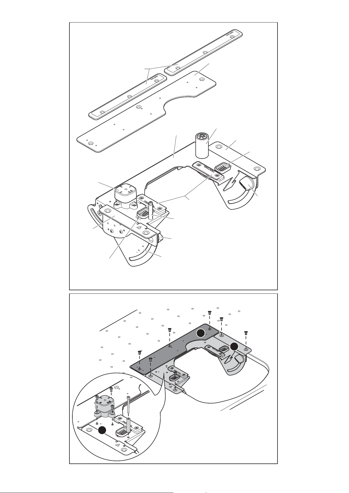
3Geräteelemente
[1-1]
[1-2]
[1-3]
[1-4]
[1-5]
[1-6]
[1-7]
[1-8]
[1-9]
Gleitplatten (15 x)
Metallbrücke
Stationärvorrichtung
Zusatzrolle
Winkelstücke
Verschlussschieber
Drehknöpfe zur Winkeleinstellung
Führungen
Führungsstift
5 Sicherheitshinweise
Warnung! Lesen Sie sämtliche Sicherheits-
hinweise und Anweisungen.
tung der Warnhinweise und Anweisungen können
elektrischen Schlag, Brand und/oder schwere Verletzungen verursachen.
Bewahren Sie alle Sicherheitshinweise und Anleitungen für die Zukunft auf.
5.1 Maschinenspezifische Sicherheitshinweise
– Beachten Sie die Betriebsanleitung des Kanten-
anleimers KA 65 und des Multifunktionstisches
MFT/3, um Gefahren und Unfälle zu vermeiden.
– Vergewissern Sie sich vor dem Arbeiten, dass
alle Drehknöpfe
[1-7]
Fehler bei der Einhal-
fest angezogen sind.
6Aufstellen
Beachten Sie die Betriebsanleitung des Multifunktionstisches MFT/3.
Sorgen Sie dafür, dass der Boden um den Arbeitstisch eben, in gutem Zustand und frei
von lose herumliegenden Gegenständen
(z.B. Spänen und Schnittresten) ist.
[1-10]
[1-11]
Die angegebenen Abbildungen befinden sich am
Anfang der Betriebsanleitung.
Winkelskala
Führungsanschlag
4 Bestimmungsgemäße Verwen-
dung
Die Adapterplatte AP-KA 65 dient zur stationären
Verwendung des Kantenanleimers KA 65, zum Anbringen von Kantenbändern aus Holz, holzähnlichen Werkstoffen und Kunststoff.
7 Montage in Lochplatte LP-KA 65
MFT/3
7.1 Montage der Adapterplatte [2]
Die Teile wie folgt montieren:
Die Stationärvorrichtung
[1-5]
stücken
Die Metallbrücke
richtung
Den Führungsstift
schlag
schrauben.
[1-11]
festschrauben.
[1-3]
schrauben.
auf die Stationärvorrichtung
[1-2]
[1-9]
[1-3]
an den Winkel-
über die Stationärvor-
und den Führungsan-
[1-3]
7
Page 8

AP-KA 65
0°
h2
h1
h2
h1
D
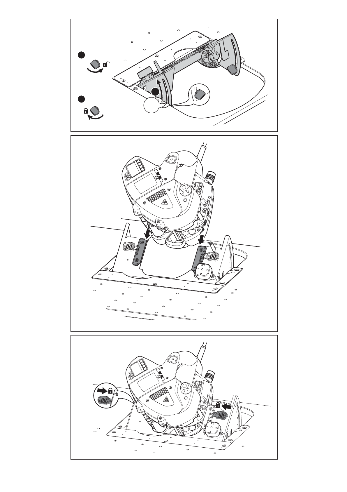
7.2 Montage des Kantenanleimers
Der Kantenanleimer kann nun in der Adapterplatte
befestigt werden:
Die Drehknöpfe zur Winkeleinstellung
[3]
[6]
.
[4]
.
[3]
.
[1-6]
[6]
gen den Uhrzeigersinn öffnen
Die Winkelskala
Die Drehknöpfe zur Winkeleinstellung
[1-10]
auf 45° einstellen
Uhrzeigersinn schließen
Den Kantenanleimer rechts und links in die
[1-8]
Führungen
Mit den Verschlussschiebern
anleimer befestigen
Die Drehknöpfe zur Winkeleinstellung
schieben
[5]
.
gen den Uhrzeigersinn öffnen
Die Winkelskala
Die Drehknöpfe zur Winkeleinstellung
[1-10]
auf 0° einstellen
Uhrzeigersinn schließen
[1-7]
.
[3]
[1-7]
den Kanten-
[1-7]
.
[6]
[1-7]
ge-
.
im
ge-
.
im
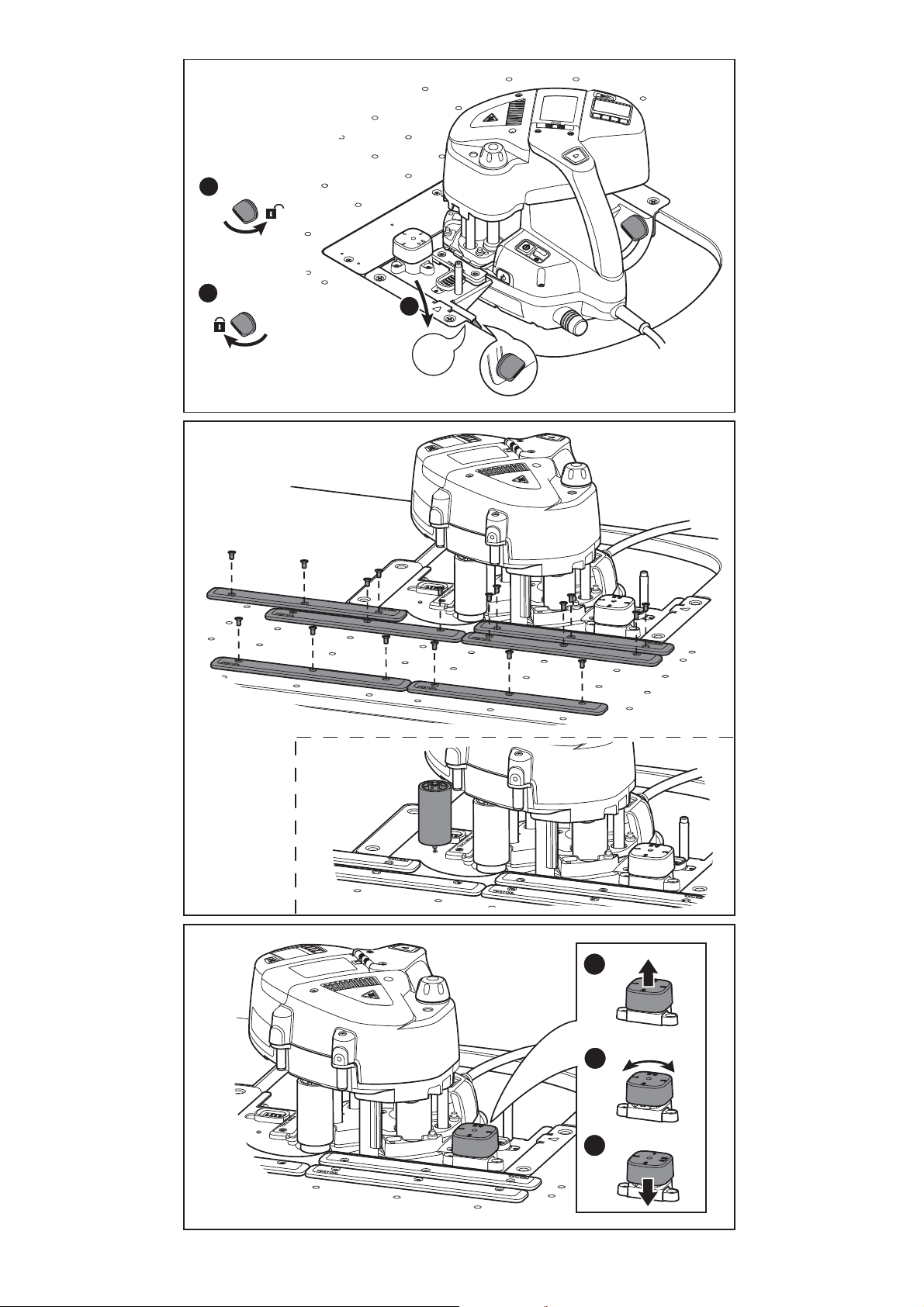
7.3 Montage der Gleitplatten [7]
Die Gleitplatten
[1-1]
werden je nach Werkstückgröße und -form auf die Lochplatte montiert, um
eine sichere Führung des Werkstücks zu gewährleisten und ein Kippen zu verhindern.
7.4 Montage der Zusatzrolle [7 A]
Die Zusatzrolle
[1-4]
kann zur Unterstützung der
Führung bei langen Werkstücken angebracht werden.
Montage durch Festschrauben im Uhrzeigersinn.
Demontage durch Abschrauben gegen den Uhrzeigersinn.
Dicke des Kantenbandes in mm Stufe
0,5 - 0,8 0,5
0,8 - 1,3 1
1,3- 2,3 2
2,3- 3,0 3
Führungsanschlag
Führungsanschlag
[1-11]
[1-11]
hochziehen.
an der Markierung
auf die Dicke der Kante einstellen.
Führungsanschlag
[1-11]
senken und einrasten
lassen.
9.2 Einstellen der Winkelskala [1-10]
Über die Winkelskala
[1-10]
kann der Winkel der
Stationärvorrichtung an die Schräge des Werkstücks angepasst werden.
Die Drehknöpfe zur Winkeleinstellung
gen den Uhrzeigersinn öffnen
Den Winkel einstellen.
Die Drehknöpfe zur Winkeleinstellung
Uhrzeigersinn schließen
[3]
[3]
.
[1-7]
ge-
.
[1-7]
im
Übersicht der erforderlichen Kantenbandhöhe in
Bezug zur Werkstückhöhe und Winkeleinstellung
Werkstückhöhe
(h1) in mm
Mindesthöhe des Kantenbandes
(h2) in mm bei Winkeleinstellung
0° 22,5° 45°
18
22
25
22 24 31
26 29 37
29 32 41
8 Montage in eigene Arbeitsplatte
Die Festool-Einbauanleitung enthält:
– Bemaßung der Ausfräsung für die Adapterplatte
– Bemaßung des Lochmusters für die Anordnung
der Gleitplatten
Nach der Vorbereitung der eigenen Arbeitsplatte kann die Montage der weiteren Elemente wie
Kapitel 7
in
fortgesetzt werden.
9 Einstellungen
9.1 Einstellen des Führungsanschlags [8]
Der Führungsanschlag
des Kantenbandes eingestellt werden. Je nach gewählter Stufe wird der Abstand des Werkstücks zur
Kleberolle ausgeglichen.
[1-11]
kann auf die Dicke
28
38
32 35 46
42 46 60
45°
8
Page 9

9.3 Einstellungen des Kantenanleimers
Beachten Sie die Betriebsanleitung des Kantenanleimers KA 65.
Der Kantenanleimer kann in der Stationärvorrichtung
nicht in die Spülstellung
bracht werden! Für den Spülvorgang muss
der Kantenanleimer aus der Stationärvorrichtung ausgebaut werden.
10 Arbeiten mit der Maschine
10.1 Anbringen des Kantenbandes
Das Kantenband hinter den Führungsstift
in die Kantenaufnahme einführen, um beim
Leimvorgang mit eingestelltem Winkel ein Abrutschen des Kantenbands zu verhindern
Start-Taste des Kantenanleimers 1 x drücken,
[9]
um den Kanteneinzug zu starten
Das Werkstück am Führungsanschlag
positionieren
Start-Taste des Kantenenleimers erneut drü-
[10]
.
cken und warten bis das Kantenband sichtbar
[10]
mit Klebstoff erscheint
Das Werkstück mit Druck auf die Andruckwalze
.
von rechts nach links am Kantenanleimer vorbeischieben
[11]
.
.
[1-11]
ge-
[1-9]
[9]
.
AP-KA 65
Bei kleinen Werkstücken kann anstatt der Gleit-
D
platten ein Holzstück mit der Höhe von 6 mm
von unten befestigt werden.
10.3 Anbringen von Vollholzkanten
Spröde Vollholzkanten brechen leicht. Zur Verhinderung können folgende Maßnahmen ergriffen
werden:
Zusatzrolle verwenden, um einen größeren Biegeradius des Kantenbandes zu erhalten.
Das Werkstück schräg im Winkel von ca. 5° -
[12]
10° zur Andruckrolle führen
.
11 Zubehör
Nur von Festool zugelassenes Zubehör und Verbrauchsmaterial verwenden. Siehe Festool-Katalog oder www.festool.com.
EKAT
1
Kundendienst und Reparatur
durch Hersteller oder durch Servicewerkstätten: Nächstgelegene Adresse
unter: www.festool.com/service
4
Nur original Festool Ersatzteile verwenden! Bestell-Nr. unter:
5
3
2
www.festool.com/service
nur
10.2 Formteile bearbeiten
Um die Bearbeitung von Formteilen zu erleichtern,
können folgende Maßnahmen ergriffen werden:
Zusatzrolle als zweiten Andruckpunkt zur Stabilität verwenden.
Gleitplatten von unten am Werkstück befestigen, z. B. mit doppelseitigem Klebeband, da
sich in fest montierten Gleitplatten das Werkstück verhaken könnte.
12 Umwelt
Werfen Sie das Gerät nicht in den Hausmüll!
ren Sie die Geräte, Zubehör und Verpackungen einer umweltgerechten Wiederverwertung zu. Beachten Sie die geltenden nationalen Vorschriften.
Informationen zur REACh:
www.festool.com/reach
Füh-
9
Page 10

AP-KA 65
GB
Original operating manual
1Technical data
Adapter plate AP-KA 65
Infinitely adjustable angle 0° - 45°
Edge height 18 - 65 mm
Edge thickness 0,5 - 3,0 mm
*
Depending on material
2Symbols
Warning of general danger
Manual, read the instructions
The user is liable for improper or non-intended use.
5 Safety instructions
Warning! Read and observe all information
and safety instructions.
*
and instructions may lead to electric shocks, fires
and/or cause serious injury.
*
Keep all safety information and other instructions
in a safe place for future reference.
5.1 Machine-related safety instructions
– Observe the operating instructions for the edge
bander KA 65 and multifunction table MFT/3 to
avoid dangers and accidents.
– Make sure that all rotary knobs
ened before starting work.
Ignoring warning notes
[1-7]
are tight-
Do not throw in the household waste.
Tip or advice
3 Machine features
[1-1]
[1-2]
[1-3]
[1-4]
[1-5]
[1-6]
[1-7]
[1-8]
[1-9]
[1-10]
[1-11]
The specified illustrations appear at the beginning
of the Operating Instructions.
Guide plates (15 x)
Metal bridge
Stationary fixture
Additional roller
Angle adapters
Sealing slide
Rotary knobs for angle adjustment
Guides
Guide pin
Angle scale
Guide rail adapter
4 Intended use
The adapter plate AP-KA 65 is designed for stationary use of the edge bander KA 65 as well as attaching edge bands made from wood, materials with
similar properties to wood and plastic.
Adapter plate installation options:
– in perforated board LP-KA 65 MFT/3 in conjunc-
tion with multifunction table MFT/3,
– in cut-out in a separate work plate and a suitable
bench according to Festool installation instructions.
6Setup
Observe the operating instructions for the
multifunction table MFT/3.
Ensure that the floor around the machine is
level, in good condition and free of loose ob-
jects (e.g. chips and offcuts).
7 Installation in perforated board
LP-KA 65 MFT/3
7.1 Fitting the adapter plate [2]
Install the components as follows:
Screw the stationary fixture
adapters
Screw the metal bridge
fixture
Screw the guide pin
adapter
[1-5]
[1-3]
[1-11]
.
.
[1-9]
onto the stationary fixture
7.2 Installing the edge bander
The edge bander can now be secured in the adapter
plate:
Release the rotary angle adjustment knobs
7]
by turning anticlockwise
Adjust the angle scale
Tighten the rotary angle adjustment knobs
by turning clockwise
Slide the edge bander to the right and left in the
guides
Secure the edge bander using the sealing slides
[1-6] [5]
Release the rotary angle adjustment knobs
7]
Adjust the angle scale
Tighten the rotary angle adjustment knobs
[1-8] [4]
.
by turning anticlockwise
.
by turning clockwise
[1-10]
[3]
[1-10]
[6]
[1-3]
to the angle
[1-2]
over the stationary
and the guide rail
[3]
.
to 45°
[3]
.
[6]
.
to 0°
[6]
.
.
[1-3]
[1-
.
[1-7]
[1-
[1-7]
.
10
Page 11

7.3 Fitting the guide plates [7]
0°
h2
h1
h2
h1
The guide plates
[1-1]
are mounted on the perforated board according to the size and shape of the
workpiece to ensure safe guidance of the workpiece and prevent it from tipping.
7.4 Fitting the additional roller [7 A]
The additional roller
[1-4]
can be fitted to help
guide the machine more accurately along long
workpieces.
Turn clockwise to mount securely in position.
Unscrew anticlockwise to remove.
AP-KA 65
GB
Overview of required edge band width in relation
to the workpiece height and angle setting
Workpiece
height (h1) in
Minimum height of the edge band
(h2) in mm for angle setting
mm
0° 22.5° 45°
18
22
25
28
22 24 31
26 29 37
29 32 41
32 35 46
8 Installing in a separate work plate
The Festool installation instructions contain:
– Dimensions of the cut-out for the adapter plate
– Dimensions of the hole pattern for positioning
the guide plates
After preparing the separate work plate, you
can continue fitting the other elements as described in
chapter 7
.
9 Settings
9.1 Adjusting the guide rail adapter [8]
The guide rail adapter
match the thickness of the edge band. The distance
between the workpiece and the adhesive roll can be
adjusted depending on the setting selected.
Thickness of the edge band in mm Setting
0.5 - 0.8 0.5
0.8 - 1.3 1
1.3- 2.3 2
2.3- 3.0 3
Lift the guide rail adapter
Change the setting to adjust the guide rail
adapter
Lower the guide rail adapter
[1-11]
to the thickness of the edge.
in position.
9.2 Adjusting the angle scale [1-10]
The angle scale
[1-10]
gle of the stationary fixture to the sloping surface of
the workpiece.
Release the rotary angle adjustment knobs
by turning anticlockwise
7]
Set the angle.
Tighten the rotary angle adjustment knobs
by turning clockwise
[1-11]
can be adjusted to
[1-11]
.
[1-11]
and engage
can be used to adapt the an-
[3]
.
[3]
.
[1-
[1-7]
38
42 46 60
45°
9.3 Edge bander settings
Observe the operating instructions for the
edge bander KA 65.
The edge bander
ing position
cannot be moved to purg-
in the stationary fixture! In order
to carry out purging, the edge bander must
be removed from the stationary fixture.
10 Working with the machine
10.1 Attaching the edge band
Guide the edge band behind the guide pin
on the edging infeed to prevent the edge band
from slipping at the preset angle during the gluing process
Press the start button on the edge bander once
to start feeding in the edging
Position the workpiece on the guide rail adapter
[1-11] [10]
Press the start button on the edge bander again
and wait until adhesive visibly appears on the
edge band
Push the workpiece from right to left past the
edge bander while applying pressure on the
contact roller
[9]
.
[10]
.
.
[11]
[9]
.
.
[1-9]
11
Page 12

AP-KA 65
GB
10.2 Processing shaped parts
The following measures make processing of
shaped parts easier:
Use an additional roller as a second contact
point for extra stability.
Secure guide plates to the underside of the
workpiece, e.g. using double-sided adhesive
tape because the workpiece could become
stuck if the guide plates are fixed.
On small workpieces, a piece of wood 6 mm
thick can be secured to the underside of the
workpiece instead of the guide plates.
10.3 Attaching solid wood edging
Brittle solid wood edging breaks easily. The following preventive measures can be taken:
Use an additional roller to increase the bending
radius of the edge band.
Guide the workpiece at an angle of approx. 5° -
[12]
10° in relation to the contact roller
.
11 Accessories
Always use accessories and consumable materials
approved by Festool. See Festool catalogue or
www.festool.com.
Customer service and repair
only
through manufacturer or service
workshops: Please find the nearest
address at: www.festool.com/service
EKAT
4
Use only original Festool spare parts!
Order No. at: www.festool.com/service
5
3
2
1
12 Environment
Do not dispose of the device together with domestic waste!
packaging at an environmentally responsible recycling centre. Observe the valid national regulations.
Information on REACh:
Dispose of machines, accessories and
www.festool.com/reach
12
 Loading...