

Page 1
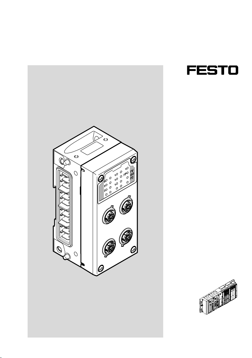
Ausgangsmodul
Output module
CPX-FVDA-P2
de Kurz
beschreibung
en Brief
description
8063239
2018-02a
[8063237]
Page 2
CPX-FVDA-P2
Symbole/Symbols: Originalbetriebsanleitung
Warnung
Warning
Einbau und Inbetriebnahme darf nur durch Fach
personal mit entsprechender Qualifikation gemäß
dieser Bedienungsanleitung durchgeführt
werden.
Vorsicht
Caution
Hinweis
Note
Translation of the original instructions
Installation and commissioning may only be per
formed in accordance with these instructions by
technicians with appropriate qualifications.
Umwelt
Environment
Zubehör
Accessories
Deutsch – Ausgangsmodul CPX-FVDA-P2 3..............................................
English – Output module CPX-FVDA-P2 31................................................
2 Festo – CPX-FVDA-P2-Z6 – 2018-02a
Page 3

CPX-FVDA-P2
Deutsch – Ausgangsmodul CPX-FVDA-P2
Inhaltsverzeichnis
1 Sicherheitshinweise 4.......................................................
1.1 Bestimmungsgemäße Verwendung 5...........................................
1.2 Regeln zum Produktaufbau 6.................................................
1.3 Vorhersehbare Fehlanwendung 8..............................................
1.4 Erreichbares Sicherheitsniveau 9..............................................
1.5 Ausfälle aufgrund gemeinsamer Ursache (Common Cause Failure – CCF) 9..............
1.6 Voraussetzungen für den Produkteinsatz 10.......................................
1.7 Technische Voraussetzungen 10................................................
1.8 Qualifikation des Fachpersonals 11..............................................
1.9 Transport- und Lagerbedingungen 11............................................
1.10 Service 11.................................................................
1.11 Einsatzbereich und Zulassungen 12.............................................
2 Produktidentifikation 13......................................................
3 Anschluss- und Anzeigeelemente 15............................................
3.1 Aufbau des Ausgangsmoduls 15................................................
4 Installation 16..............................................................
4.1 PROFIsafe-Adresse einstellen 17................................................
4.2 Demontage des Elektronikmoduls 18............................................
4.3 Montage des Elektronikmoduls 19..............................................
4.4 Pin-Belegung 20.............................................................
5 Inbetriebnahme 22..........................................................
5.1 Startverhalten des Ausgangsmoduls 22..........................................
6 Wartung, Reparatur, Entsorgung 24.............................................
7 Technische Daten 25.........................................................
Festo – CPX-FVDA-P2-Z6 – 2018-02a Deutsch 3
Page 4
CPX-FVDA-P2
1 Sicherheitshinweise
Warnung
Missachtung von Sicherheitsvorschriften kann Tod, schwere Verletzungen oder hohe
Sachschäden zur Folge haben.
Beachten Sie unbedingt die Sicherheitshinweise.
Hinweis
Elektronikmodule enthalten elektrostatisch gefährdete Bauelemente.
Unsachgemäße Handhabung kann zur Beschädigung der Elektronikmodule führen.
Beachten Sie die Handhabungsvorschriften für elektrostatisch gefährdete Bauele
mente.
Entladen Sie sich vor dem Ein- oder Ausbau von Baugruppen elektrostatisch, zum
Schutz der Baugruppen vor Entladung statischer Elektrizität.
Hinweis
Zur Sicherstellung der bestimmungsgemäßen Verwendung:
Schalten Sie jeden verwendeten Ausgangskanal mindestens einmal pro Woche.
Bei abgeschalteten Testpulsen:
Schalten Sie jeden verwendeten Ausgang mindestens einmal pro Tag.
Hinweis
Zur Sicherstellung des Sicherheitsniveaus:
Schalten Sie jeden verwendeten Ausgangskanal mindestens einmal pro 8Stunden
Betriebszeit für länger als 1 Minute ein.
Die Betriebszeit beginnt mit dem ersten Einschalten des Ausgangsmoduls.
Hinweis
Verwenden Sie maximal 2 Ausgangskanäle in einem gemeinsamen sicherheits
gerichteten Steuerkreis.
Beachten Sie die Vorschriften zur elektrischen Versorgung (Protective ExtraLow Voltage,
PELV) von CPXTerminals in der CPXSystembeschreibung P.BECPXSYS….
4 Festo – CPX-FVDA-P2-Z6 – 2018-02a Deutsch
Page 5
CPX-FVDA-P2
1.1 Bestimmungsgemäße Verwendung
Das Ausgangsmodul CPX-FVDA-P2 wird bestimmungsgemäß als Abschaltmodul zur sicheren
Abschaltung angeschlossener Verbraucher (Sicherheitsfunktion) eingesetzt, wenn die folgende
Bedingung eingehalten wird:
– Die angeschlossenen Verbraucher gehen bei Sicherheitsabschaltung in einen sicheren Zustand.
Die Sicherheitsfunktion wird realisiert durch zweikanaliges, P- und M-seitiges Abschalten folgender
Lastspannungsversorgungen des CPX-Terminals:
– Lastspannungsversorgung für Ventile U
Hierüber werden rechtsseitig montierte Module der Ventilinselpneumatik des CPX-Terminals ver
sorgt.
– Zwei über die Anschlusstechnik des Moduls bereitgestellte Ausgänge (AusgangskanalCH1 und CH2
des Moduls), ebenfalls gespeist über U
Zusätzlich wird über die Anschlusstechnik des Moduls die nicht geschaltete Lastspannungsversor
gung U
als Betriebsspannung für die externe Komponenten zur Verfügung gestellt (Hilfsversor
VAL
gung DC 24 V).
Die Ausgangskanäle des CPX-FVDA-P2 bilden mit ihren angeschlossenen Verbrauchern jeweils einen
Sicherheitskreis.
Das Ausgangsmodul CPX-FVDA-P2 ist ein Produkt mit sicherheitsrelevanten Funktionen, zum Einbau in
Maschinen bzw. automatisierungstechnischen Anlagen bestimmt und folgendermaßen einzusetzen:
– im technisch einwandfreien Zustand
– im Originalzustand ohne eigenmächtige Veränderungen
– ausschließlich in den in der Beschreibung P.BECPXFVDAP2... genannten Konfigurationen
– innerhalb der durch die technischen Daten definierten Grenzen des Produkts (èKapitel 7)
– im Industriebereich
des CPX-Terminals (AusgangskanalCH0 des Moduls).
VAL
.
VAL
Hinweis
Beachten Sie, dass die sicherheitstechnischen Systemgrenzen des Ausgangsmoduls
seine physikalischen Grenzen sind.
Festo – CPX-FVDA-P2-Z6 – 2018-02a Deutsch 5
Page 6
CPX-FVDA-P2
1.2 Regeln zum Produktaufbau
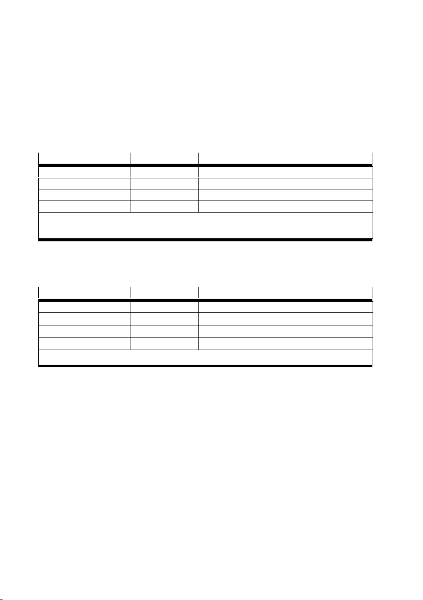
– Der Betrieb des Ausgangsmoduls CPX-FVDA-P2 ist ausschließlich in CPX-Terminals von Festo der
Variante CPX-M-... zulässig.
– Alle technischen Betriebsgrenzen sind einzuhalten (è Technische Daten).
Andernfalls können Funktionsstörungen auftreten.
– Der Betrieb des CPX-FVDA-P2 ist nur in Verbindung mit folgenden PROFIsafe-fähigen CPX-Busknoten
zulässig (èTypenschild Busknoten):
Busknoten ab Revision Netzwerk-Protokoll
CPX-FB13
CPX-FB33
CPX-FB34
CPX-FB35
1)
2)
Tab. 1 Zulässige PROFIsafe-fähige CPX-Busknoten
– Der Betrieb des CPX-FVDA-P2 innerhalb von CPXVentilinseln ist nur mit folgenden Ventiltypen
zulässig:
Ventilinsel Typ Ventiltypen
MPASFBVI 32 MPA1, MPA2 auf VMPA…FBEMG…
MPAFFBVI 33 MPAF1, MPAF2 auf VMPA…FBEMG…
VTSA-FB-VI 44 Alle bis Baubreite 52 mm
VTSA-F-FBVI 45 Alle bis Baubreite 52 mm
1)
Tab. 2 Zulässige Ventiltypen
1)
2)
2)
2)
30 PROFIBUS
21 PROFINET IO
21 PROFINET IO
21 PROFINET IO
èBeschreibung P.BE-CPX-FB13...
èBeschreibung P.BE-CPX-PNIO...
1)
1)
èBei Überschreitung des Summenstroms sind Funktionsstörungen möglich.
1)
1)
– Der Betrieb von Abschaltgruppen innerhalb von CPX-Ventilinseln ist nur in Verbindung mit zulässiger
Pneumatik erlaubt (èBeschreibung zur jeweiligen Ventilinsel).
6 Festo – CPX-FVDA-P2-Z6 – 2018-02a Deutsch
Page 7
CPX-FVDA-P2
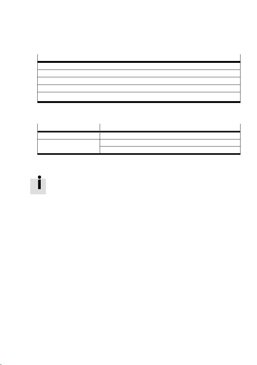
– Der Betrieb von Abschaltgruppen in CPXTerminals bei Betriebsart Remote I/O ist nur mit folgenden
dafür zugelassenen Ausgangsmodulen erlaubt:
Ausgangsmodul
1)
CPX-4DA
1)
CPX-8DA
CPX-8DA-H
CPX-8DE-8DA
1)
1)
1)
èBei Überschreitung des Summenstroms sind Funktionsstörungen möglich.
Tab. 3 Zulässige Ausgangsmodule
– Zum Aufbau des CPX-FVDA-P2 sind nur folgende Komponenten zulässig:
Komponente Typ
Verkettungsblock CPX-M-GE-EV-FVO
Anschlussblock CPX-M-AB-4-M12X2-5POL
CPX-AB-8-KL-4POL
Tab. 4 Zulässige Komponenten
Weitere Informationen über die unterstützten Produktausführungen von CPX finden Sie in
der Beschreibung P.BECPXFVDAP2... .
Ausführliche Informationen über das Produkt, die unterstützten Produktausführungen
und erforderlichen Software-Stände sowie die zulässigen Komponenten des CPX-Termi
nals finden Sie in der CPX-Systembeschreibung P.BE-CPX-SYS-… (è www.festo.com/pk).
Informationen über zulässige Konfigurationen des CPX-Terminals in Verbindung mit dem
Ausgangsmodul finden Sie im Katalog (èwww.festo.com/catalogue).
Festo – CPX-FVDA-P2-Z6 – 2018-02a Deutsch 7
Page 8
CPX-FVDA-P2
1.3 Vorhersehbare Fehlanwendung
Zur nicht bestimmungsgemäßen Verwendung gehören folgende vorhersehbare Fehlanwendungen:
– der Einsatz im Außenbereich
– der Einsatz im nicht-industriellen Bereich
– der Einsatz außerhalb der durch die technischen Daten definierten Grenzen des Produkts
– eigenmächtige Veränderungen
– der Einsatz in Kombination mit Verbrauchern, bei denen das Abschalten zu gefährlichen Bewegun
gen oder Zuständen führen kann
Hinweis
Die Verwendung von nicht genannten Anschluss und Verkettungsblöcken ist nicht zu
lässig.
Hinweis
In folgenden Fällen ist der Einsatz des Ausgangsmoduls CPX-FVDA-P2 zur Bildung von
Sicherheitskreisen nicht zulässig:
– in einem CPX-Terminal, das mit CPX-FEC oder CPX-CEC bestückt ist
– in einem CPX-Terminal mit Abschaltgruppen, die andere als die zulässigen Ausgangs
module enthalten
– in einem CPX-Terminal der Variante P
– in einem CPXTerminal mit angeschlossener Ventilinsel, die mit anderen als den
folgenden Ventiltypen bestückt ist: VTSA, MPA-S, MPA-F (èTab. 2)
– in einem CPXTerminal mit angeschlossener Ventilinsel, bei der sich VPPM in si
cherheitsgerichtet abschaltbaren Schaltgruppen befinden
– in unzulässigen Schaltungskonfigurationen (èBeschreibung P.BECPXFVDAP2...)
Hinweis
Das Ausgangsmodul enthält keine Verschleißteile. Reparaturen am Ausgangsmodul
CPX-FVDA-P2 sind unzulässig. Dadurch erlischt die Zulassung des Ausgangsmoduls.
Ein fachgerechter Austausch des Elektronikmoduls durch den Anwender ist zulässig.
Hinweis
Bei Schäden, die aus unbefugten Eingriffen oder nicht bestimmungsgemäßer
Verwendung entstehen, erlischt der Gewährleistungs- und Haftungsanspruch gegen
über dem Hersteller.
8 Festo – CPX-FVDA-P2-Z6 – 2018-02a Deutsch
Page 9

CPX-FVDA-P2
1.4 Erreichbares Sicherheitsniveau
Mit dem CPX-FVDA-P2 können Sicherheitsfunktionen realisiert werden bis:
– Sicherheitsintegritätslevel SIL 3 nach IEC 61508
– Performance Level e, Kat. 3 nach EN ISO 13849-1
– SIL Claim Limit SIL CL 3 nach EN 62061.
Das erreichbare Sicherheitsniveau der gesamten Sicherheitseinrichtung hängt von weiteren Kompo
nenten ab, die zur Realisierung der Sicherheitsfunktion genutzt werden.
Zur Erhaltung des Sicherheitsniveaus:
Prüfen Sie die Funktionsfähigkeit der Sicherheitseinrichtung in angemessenen Zeitabständen.
1.5 Ausfälle aufgrund gemeinsamer Ursache (Common Cause Failure – CCF)
Ausfälle aufgrund gemeinsamer Ursache bewirken den Verlust der Sicherheitsfunktion, da in einem
zweikanaligen System beide Kanäle (P und M) gleichzeitig ausfallen.
Durch folgende Maßnahmen stellen Sie sicher, dass Ausfälle aufgrund gemeinsamer Ursache vermie
den werden:
Betriebsspannungsgrenzen einhalten
Temperaturbereich einhalten
max. 2 Ausgangskanäle in einem gemeinsamen sicherheitsgerichteten Steuerkreis verwenden
Aus der Anwendung können sich weitere Maßnahmen zur Vermeidung von Ausfällen gemeinsamer
Ursache ergeben.
Festo – CPX-FVDA-P2-Z6 – 2018-02a Deutsch 9
Page 10

CPX-FVDA-P2
1.6 Voraussetzungen für den Produkteinsatz
Stellen Sie diese Kurzbeschreibung dem Konstrukteur, Monteur und dem für die Inbetriebnahme
zuständigen Personal der Maschine oder Anlage, an der dieses Produkt zum Einsatz kommt, zur
Verfügung.
Bewahren Sie diese Kurzbeschreibung während des gesamten Produktlebenszyklus auf.
Stellen Sie sicher, dass die Vorgaben der Dokumentation stets eingehalten werden.
Berücksichtigen Sie hierbei auch die Dokumentation zu den weiteren Komponenten und Modulen
(z. B. Busknoten, Pneumatik usw.).
Berücksichtigen Sie die für den Bestimmungsort geltenden gesetzlichen Regelungen sowie:
– Vorschriften und Normen
– Regelungen der Prüforganisationen und Versicherungen
– nationale Bestimmungen
Entfernen Sie die Verpackungen wie Folien, Kappen, Kartonagen. Die Verpackungen sind vorgese
hen für eine Verwertung auf stofflicher Basis (Ausnahme: Ölpapier = Restmüll).
Führen Sie die Montage fachgerecht aus. Zur Erhaltung der IP-Schutzart:
– Anschlussblock dicht verschrauben (èMontage des Elektronikmoduls).
– Kabeleinführung und Abdichtungen fachgerecht montieren.
– Nicht benutzte Anschlüsse mit Abdeckkappen verschließen.
Stellen Sie sicher, dass nach einer Sicherheitsanforderung wie einem NOT-HALT der Neustart der
Anlage bestimmungsgemäß nur unter Kontrolle der Sicherheitssteuerung erfolgt.
1.7 Technische Voraussetzungen
Allgemeine, stets zu beachtende Hinweise für den ordnungsgemäßen und sicheren Einsatz des Pro
dukts:
Halten Sie die technischen Betriebsgrenzen ein (è Technische Daten).
Nur dann ist der Betrieb des Produkts gemäß der einschlägigen Sicherheitsrichtlinien gewährleistet.
Beachten Sie beim Anschluss handelsüblicher Zusatzkomponenten ebenfalls die angegebenen
Grenzwerte für Temperaturen, elektrische Daten und Momente.
10 Festo – CPX-FVDA-P2-Z6 – 2018-02a Deutsch
Page 11
CPX-FVDA-P2
1.8 Qualifikation des Fachpersonals
Das Gerät darf nur von ausgebildeten Fachleuten der Steuerungs- und Automatisierungstechnik in
Betrieb genommen werden, die vertraut sind mit:
– der Installation und dem Betrieb von Steuerungssystemen
– den geltenden Vorschriften zum Betrieb sicherheitstechnischer Anlagen
– den geltenden Vorschriften zur Unfallverhütung und Arbeitssicherheit
– der Dokumentation zum Produkt
Hinweis
Arbeiten an sicherheitstechnischen Systemen dürfen nur von berechtigten, sicherheits
technisch sachkundigen Fachleuten durchgeführt werden.
1.9 Transport- und Lagerbedingungen
Schützen Sie das Produkt bei Transport und Lagerung vor unzulässigen Beanspruchungen wie:
– mechanischen Belastungen
– unzulässigen Temperaturen
– Feuchtigkeit
– aggressiven Atmosphären
Lagern und transportieren Sie das Produkt in der Originalverpackung.
Die Originalverpackung bietet ausreichenden Schutz vor üblichen Beanspruchungen.
1.10 Service
Bitte wenden Sie sich bei technischen Problemen an Ihren lokalen Service von Festo.
Festo – CPX-FVDA-P2-Z6 – 2018-02a Deutsch 11
Page 12
CPX-FVDA-P2
1.11 Einsatzbereich und Zulassungen
Das Produkt ist ein Sicherheitsbauteil nach EU-Maschinen-Richtlinie und mit dem CE-Kennzeichen
versehen.
Normen und Prüfwerte, die das Produkt einhält und erfüllt, finden Sie im Abschnitt
Technische Daten. Die produktrelevanten EGRichtlinien entnehmen Sie bitte der Kon
formitätserklärung. Zertifikate und die Konformitätserklärung zu diesem Produkt finden
Sie auf www.festo.com.
Beachten Sie, dass sich die Einhaltung der genannten Normen auf das Ausgangsmodul
CPX-FVDA-P2 beschränkt. Aus Sicht des Ausgangsmoduls werden alle dadurch abschaltbaren Teile
eines CPXTerminals bzw. einer Ventilinsel wie eine externe Last behandelt.
Bestimmte Konfigurationen des Produkts besitzen eine Zertifizierung von Underwriters Laboratories
Inc. (UL) für die USA und Kanada.
Diese Konfigurationen sind folgendermaßen gekennzeichnet:
UL Recognized Component Mark for Canada and the United States
Only for connection to a NEC Class 2 supply.
Raccorder Uniquement a un circuit de Classe 2.
Hinweis
Wenn in Ihrem Einsatzfall die Anforderungen von UL einzuhalten sind, beachten Sie
Folgendes:
– Vorschriften zur Einhaltung der UL-Zertifizierung finden Sie in der separaten
UL-spezifischen Spezialdokumentation.
Es gelten vorrangig die dortigen technischen Daten, insofern sie die sicherheits
technischen Kennwerte nicht in unzulässiger Weise beeinflussen.
– Die technischen Daten in der vorliegenden Dokumentation können davon
abweichende Werte aufweisen.
12 Festo – CPX-FVDA-P2-Z6 – 2018-02a Deutsch
Page 13
CPX-FVDA-P2
2 Produktidentifikation
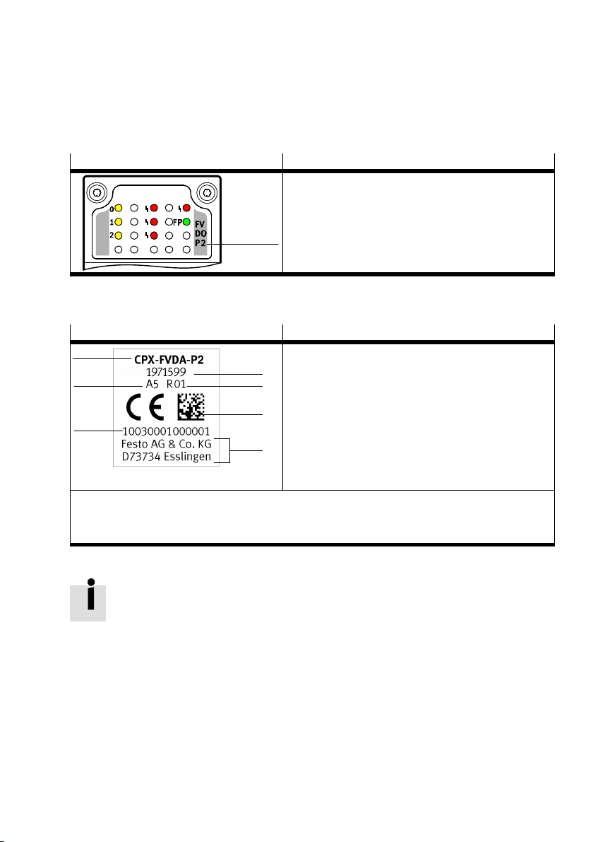
Zur Produktidentifikation dient die Modulkennung und das Typenschild des Produkts.
Die Modulkennung ist durch die transparente Abdeckung des Anschlussblocks sichtbar.
Modulkennung
Tab. 5 Modulkennung des Ausgangsmoduls CPX-FVDA-P2
Das Typenschild des Elektronikmoduls CPX-FVDA-P2 (è Fig. 1 7 ) zeigt folgende Informationen:
Typenschild (Beispiel) Bedeutung
1
7
6
1)
Teilenummer des Elektronikmoduls CPX-FVDA-P2
2)
Ermöglicht die Rückverfolgbarkeit des Produkts.
3)
è Beschreibung P.BE-CPX-FVDA-P2-…
Tab. 6 Typenschild des Elektronikmoduls CPX-FVDA-P2
Bedeutung
– Modulkennung 1 : FVDOP2
(F=Safety; V=Valves;
D=Digital; O=Outputs;
P=PROFIsafe; 2=Variante)
1
Typenschild
2
– Typenbezeichnung 1
– Teilenummer 2
3
– Revisionscode (hier R01) 3
– Seriennummer dargestellt als Datamatrixcode 4
4
– Hersteller und Herstelleradresse 5
– 14-stellige Seriennummer 6
5
– Fertigungszeitraum (verschlüsselt,
hier A5 = Mai 2010) 7
1)
2)
3)
2)
Weitere Informationen hierzu finden Sie in der CPX-Systembeschreibung
P.BE-CPX-SYS-... .
Festo – CPX-FVDA-P2-Z6 – 2018-02a Deutsch 13
Page 14
CPX-FVDA-P2
Prüfen Sie vor dem Austausch eines Moduls, ob die Revision des Busknotens den Anforderungen
des Moduls entspricht (è Tab. 1).
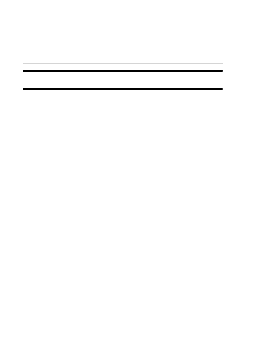
Gültigkeitsbereich der vorliegenden Kurzbeschreibung
Typ Teilenummer Revision
CPX-FVDA-P2 1971599 R0x
1)
x steht hier für eine einstellige Zahl von 1 bis 9 (èTab. 6 3 )
Tab. 7 Gültigkeitsbereich
1)
14 Festo – CPX-FVDA-P2-Z6 – 2018-02a Deutsch
Page 15
CPX-FVDA-P2
3 Anschluss- und Anzeigeelemente
3.1 Aufbau des Ausgangsmoduls
aJ
1
9
8
3
4
7
5
6
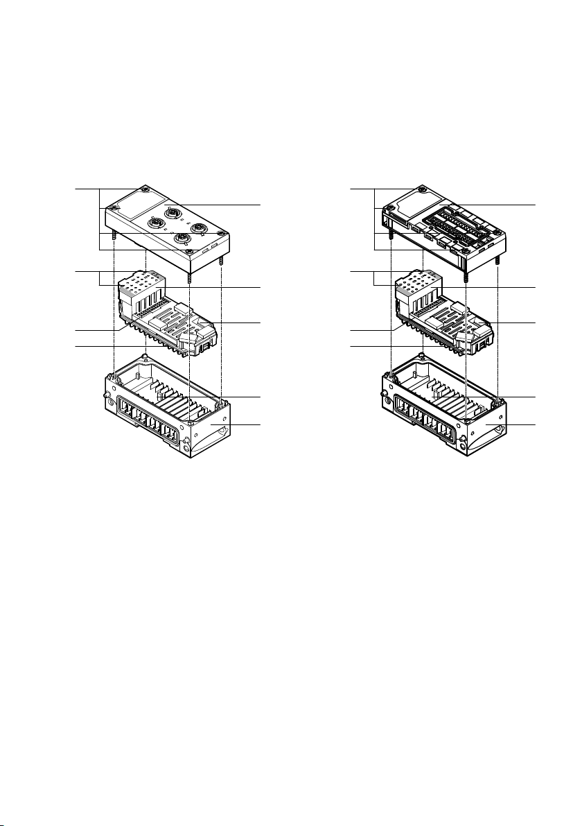
1 Anschlussblock CPX-M-AB-4-M12X2-5POL
2 Anschlussblock CPX-AB-8-KL-4POL
3 Elektronikmodul CPX-FVDA-P2
4 10fach-DIL-Schalter für PROFIsafe-Adresse
5 Mechanische Codierung
6 Verkettungsblock mit Stromschienen
CPX-M-GE-EV-FVO
Fig. 1 Aufbau des Ausgangsmoduls CPX-FVDA-P2
aJ
9
8
7
7 Typenschild (auf der Unterseite)
8 Elektrische Steckverbindung zwischen
Elektronikmodul und Anschlussblock
9 LEDs des Elektronikmoduls
aJ Schrauben
2
3
4
5
6
Festo – CPX-FVDA-P2-Z6 – 2018-02a Deutsch 15
Page 16
CPX-FVDA-P2
4 Installation
Warnung
Verwenden Sie für die elektrische Versorgung ausschließlich PELV-Stromkreise nach
EN 60204-1 (Protective Extra-Low Voltage, PELV).
Berücksichtigen Sie zusätzlich die allgemeinen Anforderungen an PELV-Stromkreise
gemäß der EN 60204-1.
Verwenden Sie ausschließlich Stromquellen, die eine sichere elektrische Trennung
der Betriebsspannung nach EN 60204-1 vom Netz gewährleisten.
Stellen Sie sicher, dass defekte Kabel sofort ausgetauscht werden.
Durch die Verwendung von PELV-Stromkreisen wird der Schutz gegen elektrischen Schlag (Schutz
gegen direktes und indirektes Berühren) nach EN 60204-1 sichergestellt (Elektrische Ausrüstung von
Maschinen, Allgemeine Anforderungen).
Außerdem wird die Einhaltung der Eingangsspannungsgrenzen des Moduls sichergestellt.
Hinweis
Elektronikmodule enthalten elektrostatisch gefährdete Bauelemente.
Beachten Sie die Handhabungsvorschriften für elektrostatisch gefährdete Bauele
mente.
Entladen Sie sich vor dem Ein- oder Ausbau von Baugruppen elektrostatisch, zum
Schutz der Baugruppen vor Entladung statischer Elektrizität.
Hinweis
Die Querschlussüberwachung überwacht geräteeigene Stromkreise.
Stellen Sie sicher, dass Querschlüsse zu fremden Stromkreisen durch geeignete
Installationsmaßnahmen ausgeschlossen werden.
Schalten Sie zuerst die Versorgungsspannungen aus, bevor Sie Montage- und Installationsarbeiten
durchführen.
Schalten Sie die elektrischen Versorgungsspannungen erst ein, wenn das Produkt vollständig
montiert ist und alle Installationsarbeiten abgeschlossen sind.
16 Festo – CPX-FVDA-P2-Z6 – 2018-02a Deutsch
Page 17
CPX-FVDA-P2
4.1 PROFIsafe-Adresse einstellen
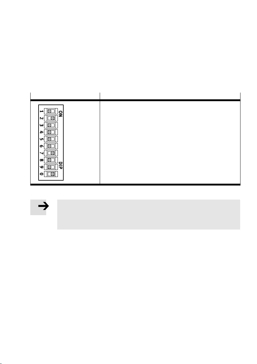
Zur Kommunikation via PROFIsafe muss am Ausgangsmodul über den 10fach-DIL-Schalter (èFig. 2)
die korrekte PROFIsafe-Adresse binär codiert eingestellt werden.
Zulässig sind die PROFIsafe-Adressen im Bereich von 1 bis 1023.
Der 10fach-DIL-Schalter befindet sich direkt auf dem Elektronikmodul und kann bei demontiertem
Anschlussblock eingestellt werden.
10fach-DIL-Schalter Adressierungsbeispiel
2 + 64 + 512 = 578
1
2
4
8
16
32
64
128
256
512
Fig. 2 10fach-DIL-Schalter des Elektronikmoduls
Hinweis
Der DIL-Schalter ist aufgrund seiner Baugröße ein mechanisch empfindliches Bauteil.
Verwenden Sie zum Einstellen ein geeignetes, kleines, stumpfes Werkzeug
(z. B. Uhrmacherschraubendreher) und gehen Sie dabei sehr behutsam vor.
1. Schalten Sie die Spannungsversorgungen des CPX-Terminal aus.
2. Nehmen Sie den montierten Anschlussblock ab (èFig. 1).
3. Stellen Sie den DIL-Schalter vorsichtig ein.
4. Montieren Sie den Anschlussblock wieder (èMontage des Elektronikmoduls).
Festo – CPX-FVDA-P2-Z6 – 2018-02a Deutsch 17
Page 18

CPX-FVDA-P2
4.2 Demontage des Elektronikmoduls
Hinweis
Unsachgemäße Handhabung kann zur Beschädigung des Elektronikmoduls führen.
Ziehen Sie das Elektronikmodul nie unter Spannung vom Verkettungsblock.
Um Fehler bei der Montage zu vermeiden, ist sowohl der Verkettungsblock
CPX-M-GE-EV-FVO als auch das Elektronikmodul CPX-FVDA-P2 mechanisch codiert.
Die Codierung verhindert, dass sich ein anderes Modul in den Verkettungsblock stecken
lässt oder das Modul in einen falschen Verkettungsblock gesteckt werden kann.
Die am Anschlussblock angeschlossenen Stecker können bei der Demontage des Anschlussblocks
montiert bleiben.
Zur Demontage:
1. Schalten Sie die Betriebs- und Lastspannungsversorgungen aus.
2. Drehen Sie die Schrauben aJ heraus und heben Sie den Anschlussblock 1 bzw. 2 vorsichtig ab
(èFig. 1).
3. Bei Bedarf: Ziehen Sie das Elektronikmodul 2 vorsichtig von den Stromschienen ab.
18 Festo – CPX-FVDA-P2-Z6 – 2018-02a Deutsch
Page 19
CPX-FVDA-P2
4.3 Montage des Elektronikmoduls
Hinweis
Unsachgemäße Handhabung kann zur Beschädigung des Elektronikmoduls führen.
Drücken Sie das Elektronikmodul nie unter Spannung in den Verkettungsblock.
Hinweis
Stellen Sie sicher, dass der Verkettungsblock (èFig. 1) sauber und frei von Fremd
körpern ist, insbesondere im Bereich der Kontaktschienen.
Prüfen Sie die Dichtungen auf Beschädigung zur Aufrechterhaltung der Schutzart
IP65/IP67.
Sorgen Sie für saubere Anschlussflächen zur Optimierung der Dichtwirkung und zur
Vermeidung von Kontaktfehlern.
Hinweis
Verwenden Sie für den Metall-Verkettungsblock CPX-M-GE-EV-FVO nur Schrauben
mit metrischem Gewinde.
Setzen Sie zur Vermeidung von Gewindebeschädigungen die Schrauben exakt an
und nutzen Sie vorhandene Gewindegänge.
Drehen Sie die Schrauben mit einem Schraubendreher nur von Hand ein.
Vermeiden Sie bei der Verschraubung jeglichen Verzug und mechanische
Spannungen.
Beachten Sie bei nachträglich bestellten Modulen und Komponenten auch die Mon
tagehinweise in der Dokumentation, die den Produkten beiliegen.
Zur Montage:
1. Schalten Sie die Betriebs- und Lastspannungsversorgungen aus.
2. Richten Sie das Elektronikmodul3 lagerichtig aus und drücken es vorsichtig in den Verkettungs
block6 hinein (èFig. 1).
3. Prüfen Sie die Dichtung und die Dichtflächen, richten Sie den Anschlussblock1 bzw. 2 lagerichtig
aus und setzen ihn auf das Elektronikmodul3.
4. Setzen Sie die SchraubenaJ so an, dass die vorhandenen Gewindegänge genutzt werden.
Ziehen Sie die Schrauben von Hand über Kreuz an.
Festo – CPX-FVDA-P2-Z6 – 2018-02a Deutsch 19
Page 20
CPX-FVDA-P2
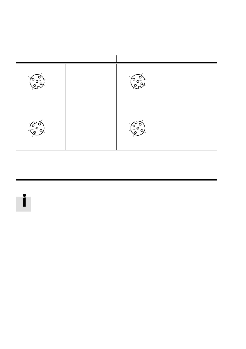
4.4 Pin-Belegung
CPX-FVDA-P2 mit Anschlussblock CPX-M-AB-4-M12X2-5POL
Pin-Belegung X1, X2 Pin-Belegung X3, X4
4
3
5
1
2
X1
Buchse X1
1: 0V CH1
2: +24V CH1
1)
1)
3: F–DO(M) CH1
4: F–DO(P) CH1
5: FE
4
3
2)
2)
5
1
2
X3
Buchse X3
1: n.c.
2: n.c.
3: n.c.
4: n.c.
5: FE
X2
2
1
5
3
4
Buchse X2
1: 0V CH2
2: +24V CH2
1)
1)
3: F–DO(M) CH2
4: F–DO(P) CH2
X4
2
1
2)
2)
5
4
5: FE
FE = Funktionserde
n.c. = frei (not connected)
1)
Ungeschaltete Spannung U
2)
Alle Ausgangsspannungen sind ebenfalls von der internen Stromschiene U
nutzbar zur Versorgung intelligenter Lastsysteme (Hilfsversorgung)
VAL
Fig. 3 CPX-FVDA-P2 mit Anschlussblock CPX-M-AB-4-M12X2-5POL
Das Metallgewinde des Anschlussblocks CPX-M-AB-4-M12X2-5POL ist intern mit Pin 5
(Funktionserde FE) verbunden.
Buchse X4
1: n.c.
2: n.c.
3
3: n.c.
4: n.c.
5: FE
abgeleitet.
VAL
20 Festo – CPX-FVDA-P2-Z6 – 2018-02a Deutsch
Page 21
CPX-FVDA-P2
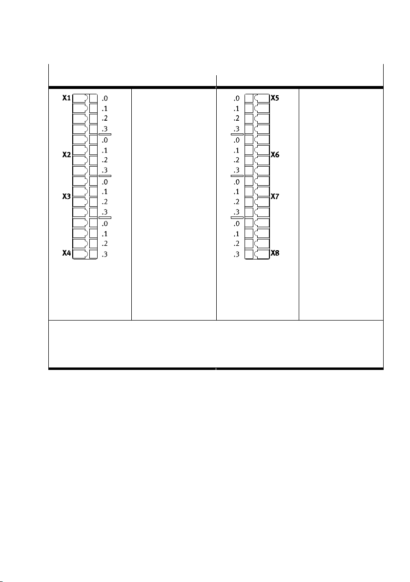
CPX-FVDA-P2 mit Anschlussblock CPX-AB-8-KL-4POL
Pin-Belegung X1, X2, X3, X4 Pin-Belegung X5, X6, X7, X8
X1
0: 0V CH1
1: F–DO (M) CH1
2: F–DO (P) CH1
1)
2)
2)
3: FE
X2
0: n.c.
1: n.c.
2: +24V CH1
1)
3: FE
X3
0: 0V CH2
1: F–DO (M) CH2
2: F–DO (P) CH2
1)
2)
2)
3: FE
X4
0: n.c.
1: n.c.
2: +24V CH2
1)
3: FE
FE = Funktionserde
n.c. = frei (not connected)
1)
Ungeschaltete Spannung U
2)
Alle Ausgangsspannungen sind ebenfalls von der internen Stromschiene U
nutzbar zur Versorgung intelligenter Lastsysteme (Hilfsversorgung)
VAL
Fig. 4 CPX-FVDA-P2 mit Anschlussblock CPX-AB-8-KL-4POL
X5
0: n.c.
1: n.c.
2: n.c.
3: FE
X6
0: n.c.
1: n.c.
2: n.c.
3: FE
X7
0: n.c.
1: n.c.
2: n.c.
3: FE
X8
0: n.c.
1: n.c.
2: n.c.
3: FE
abgeleitet.
VAL
Festo – CPX-FVDA-P2-Z6 – 2018-02a Deutsch 21
Page 22
CPX-FVDA-P2
5 Inbetriebnahme
5.1 Startverhalten des Ausgangsmoduls
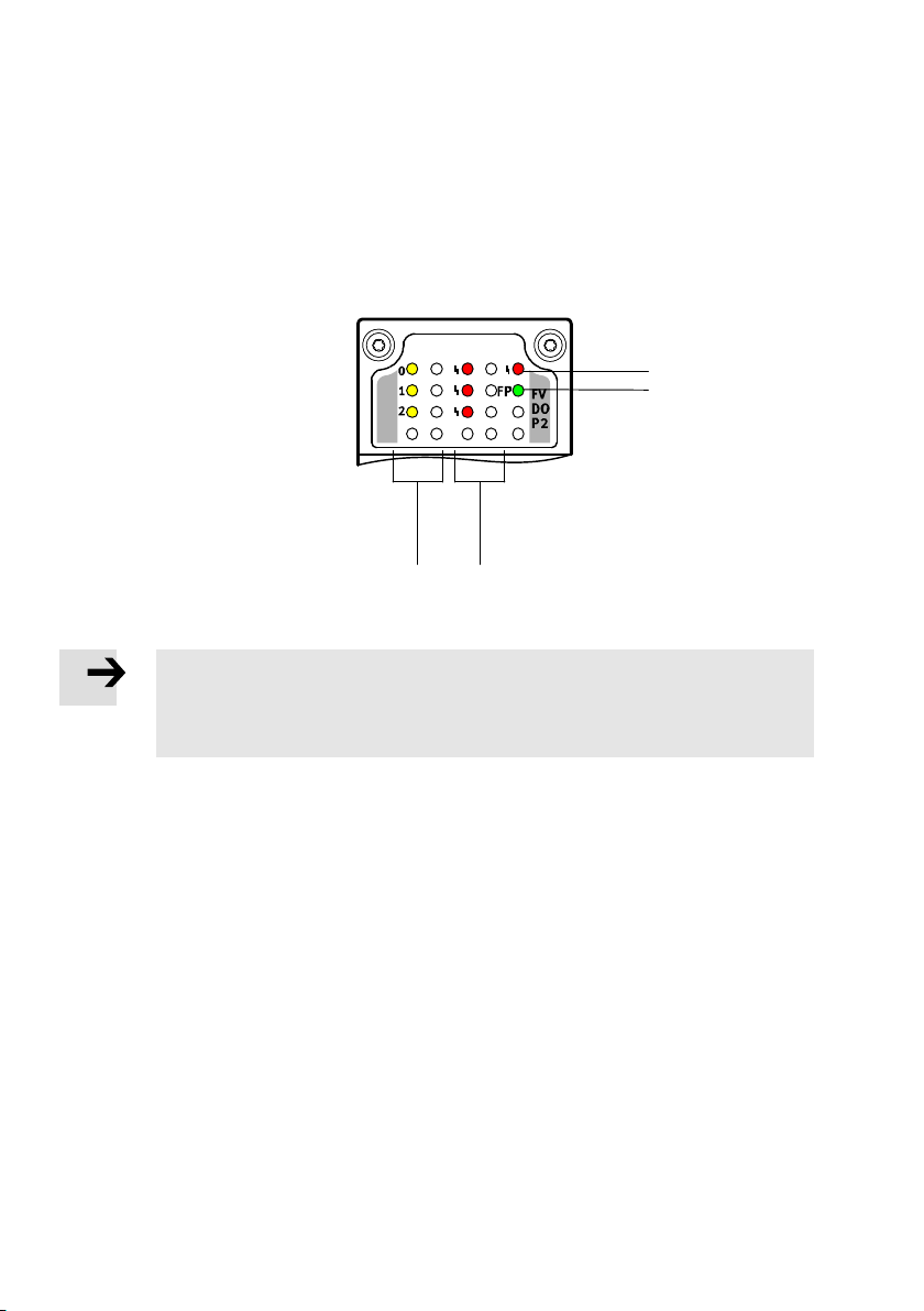
Zur Vorort-Diagnose befinden sich unter der transparenten Abdeckung des Moduls folgende LEDs:
1 Modulfehler-LED
(rot)
2 FP-LED (grün) -
Failsafe Protocol
3 Kanalfehler-LED (rot);
eine je Ausgangskanal
4 Zustands-LED (gelb);
eine je Ausgangskanal
Fig. 5 LED-Anzeige des Ausgangsmoduls CPX-FVDA-P2
Hinweis
Die LED-Anzeige des Moduls ist nicht sicherheitsgerichtet ausgeführt.
Beachten Sie, dass die LEDs nicht für sicherheitsgerichtete Maßnahmen ausge
wertet werden dürfen.
4
3
1
2
Beim Einschalten der Betriebsspannungsversorgung U
ca. 500 ms.
Beim Einschalten der Lastspannungsversorgung U
Aus Sicht des Ausgangsmoduls ist die Reihenfolge des Einschaltens beliebig.
Bei gleichzeitigem Einschalten beider Spannungsversorgungen leuchten die genannten LEDs gemein
sam auf.
Bis zur korrekten Parametrierung durch einen PROFIsafe-Master blinkt die FP-LED.
Nach korrekter Parametrierung leuchtet die FP-LED und das Modul ist betriebsbereit.
22 Festo – CPX-FVDA-P2-Z6 – 2018-02a Deutsch
VAL
leuchtet die Modulfehler-LED 1 für
EL/SEN
leuchten die Kanalfehler-LEDs 3 für ca. 1 s.
Page 23
CPX-FVDA-P2
Im normalen Betriebszustand leuchten folgende LEDs:
– FP-LED – Failsafe Protocol 2 (grün)
– Zustands-LED 4 der aktiven Ausgangskanäle (gelb)
Die Zustands-LED inaktiver Ausgangskanäle und die Modul- und die Kanalfehler-LED leuchten nicht.
Hinweis
Prüfen Sie die Funktionsfähigkeit der Sicherheitseinrichtung in angemessenen
Zeitabständen.
Es liegt in der Verantwortung des Betreibers, die Art der Überprüfung und die Zeitab
stände zwischen den Überprüfungen zu wählen.
Die Prüfung ist so durchzuführen, dass die einwandfreie Funktion der Sicherheitsein
richtung im Zusammenwirken aller Komponenten nachgewiesen wird.
Weitere Informationen finden Sie in der CPX-Systembeschreibung P.BE-CPX-SYS-….
Festo – CPX-FVDA-P2-Z6 – 2018-02a Deutsch 23
Page 24
CPX-FVDA-P2
6 Wartung, Reparatur, Entsorgung
Das Ausgangsmodul enthält keine wartungsbedürftigen Teile.
Hinweis
Das Modul enthält keine Verschleißteile. Reparaturen sind unzulässig.
Dadurch erlischt die Zulassung des Ausgangsmoduls.
Ein fachgerechter Austausch des Elektronikmoduls ist zulässig.
Hinweis
Wechseln Sie das Ausgangsmodul im Falle eines internen Defekts unbedingt aus.
Senden Sie das unveränderte, defekte Ausgangsmodul einschließlich einer
Beschreibung des Fehlers und des Einsatzfalles zur Analyse zurück an Festo.
Setzen Sie sich bitte mit Ihrem Fachberater in Verbindung, um die Modalitäten der Rücksendung zu
klären. Nennen Sie bei Reklamation bzw. Reparatur bitte folgende Angaben: Reklamationsart 2
gemäß Festo VA 19.02.
Zur endgültigen Entsorgung des Ausgangsmoduls wenden Sie sich bitte an einen zertifizierten Entsor
gungsbetrieb für Elektronikschrott.
24 Festo – CPX-FVDA-P2-Z6 – 2018-02a Deutsch
Page 25
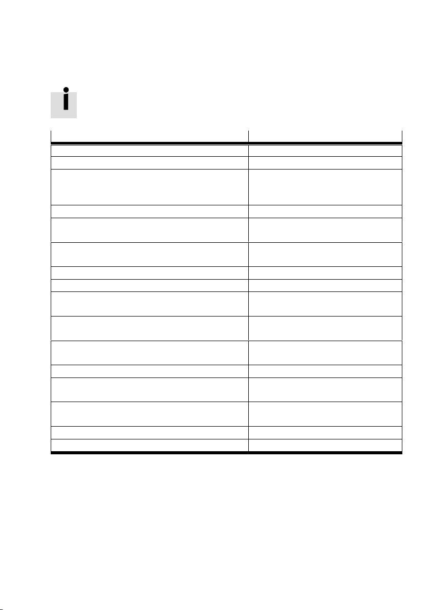
CPX-FVDA-P2
7 Technische Daten
Allgemeine technische Daten des CPX-Terminals
è CPX-Systembeschreibung P.BE-CPX-SYS-...
Elektrische Kennwerte
CPX-FVDA-P2
Nennbetriebsspannung [V DC] 24
Zulässige Spannungsschwankungen [%] –15 … +20
Betriebsspannung bei Abgriff von Strom
schiene 24 V
und 0 V
VAL
(integrierter
VAL
[V DC] 20,4 … 28,8
Verpolschutz)
Restwelligkeit (innerhalb Tol.) [Vss] 2
Spannungseinbruch Überbrückungszeit U
Eigenstromaufnahme bei Nennbetriebs
spannung
Unterspannungsüberwachung U
Überspannungsüberwachung U
Potenzialtrennung zwischen V
(resp. 5 V CBUS) und V
VAL
VAL
VAL
EL,SEN
Potenzialtrennung Ausgangskanal
[ms] 2
VAL
[mA] typ. 65 für Ventile (von U
typ. 25 für Elektronik (von U
[V] < 19,5 für t > 250ms
[V] > 29,5 für t > 250ms
[V rms] min. 500
Ja, bei Zwischeneinspeisung
(CH0, CH1, CH2) - Interner Bus
Potenzialtrennung Ausgangskanal - Aus
nein
gangskanal
Potenzialbezug der Ausgangskanäle U
Max. Stromversorgung CH0, CH1, CH2
[A] 1,5
VAL
(Laststrom je Ausgangskanal)
Max. Laststrom je ungeschalteter Spannung
U
(Hilfsversorgung)
VAL
[A] 2,5
Max. Spitzenstrom je Ausgangskanal [A] 5 für t < 30 ms
Max. Summenstrom pro Modul [A] 5
VAL
)
EL/SEN
)
Festo – CPX-FVDA-P2-Z6 – 2018-02a Deutsch 25
Page 26
CPX-FVDA-P2
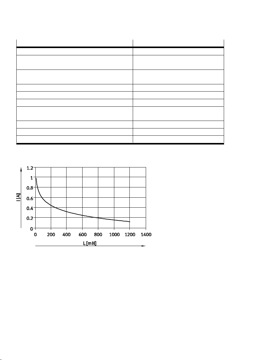
Elektrische Kennwerte CPX-FVDA-P2
Max. Schaltfrequenz der Ausgangskanäle [Hz] 1
Max. Spannungsabfall je Ausgangskanal bei
[V] 0,6
Dauerlast
Drahtbrucherkennung (CH0, CH1, CH2) parametrierbar,
Detektionsschwelle IL ca. 50 mA
Max. Leitungslänge (CH1, CH2) [m] 200
Max. Lastkapazität gegen FE [nF] 400
Max. Lastkapazität P-M [μF] 22
Max. Lastinduktivität [mH] 1000 bei 150mA, 100 bei 600mA;
èKennlinie Fig. 6
Absicherung (Kurzschluss) Integrierte elektronische Sicherung
Max. Testpulsdauer [μs] 300
Max. Spannungsabfall während Testpuls [V] 6
Tab. 8 Elektrische Kennwerte
Fig. 6 Maximal zulässige Lastinduktivität an den Ausgangskanälen
26 Festo – CPX-FVDA-P2-Z6 – 2018-02a Deutsch
Page 27
CPX-FVDA-P2
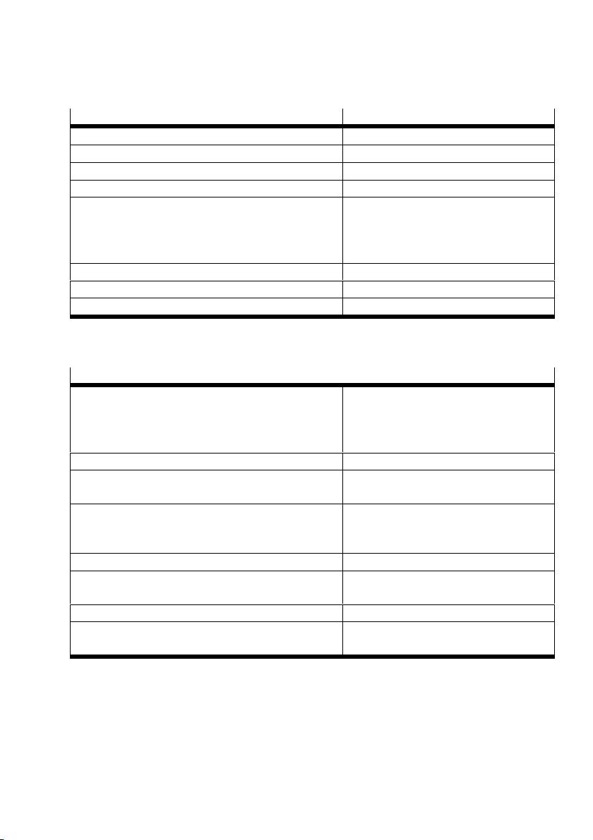
Funktionskennwerte CPX-FVDA-P2
Modulcode 193d (C1h)
Submodulcode 8d (08h)
Kompatibel mit Fast Startup (FSU) ja
StartupZeit bis Modul bereit [s] < 2
Diagnose externer Kanalfehler – Zyklische Überprüfung auf Funktion
– Zyklische Überprüfung auf Fremd
einspeisung
– Zyklische Überprüfung auf Querschluss
Reaktionszeit auf externe Kanalfehler [min] <1
Reaktionszeit auf Abschaltbefehl (typ.) [ms] <10
Interne PROFIsafe-Verarbeitungszeit (T
) [ms] < 50
DAT
Tab. 9 Funktionskennwerte
Sicherheitskennwerte
1)
Sicherheitsfunktion Sicheres Abschalten der Ausgangskanäle
– gem. IEC 61508 mit SIL 3
– gem. EN ISO 13849 mit Kat. 3, PL e
– gem. EN 62061 mit SIL CL 3
Abschaltschema je Ausgangskanal P- und M-schaltend
Interne Reaktionszeit auf Abschaltbefehl
(T
) am Ausgangskanal CH0
WCDT
Interne Reaktionszeit auf Abschaltbefehl
(T
) an den Ausgangskanälen CH1 und
WCDT
[ms] < 23
èLastdiagramme Fig. 7 und Fig. 8
CH2 in Abhängigkeit der Mindestlast
PROFIsafeWatchdogZeit F_WD_TIME
Max. Reaktionszeit der Sicherheits
[ms] F_WD_TIME +T
WCDT
funktion
Max. zyklische Anforderungsrate [1/min] 1
Mittlere Zeit bis zum gefahrbringenden
[Jahre] >750
Ausfall (MTTFd)
Festo – CPX-FVDA-P2-Z6 – 2018-02a Deutsch 27
Page 28
CPX-FVDA-P2
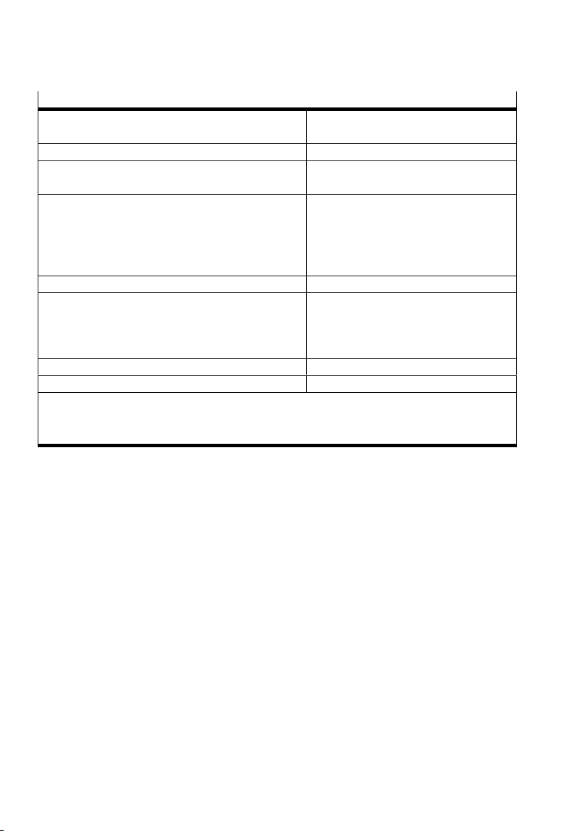
Sicherheitskennwerte
Wahrscheinlichkeit eines Gefahr
1)
[1/h] <1,0 x 10
–9
bringenden Ausfalls pro Stunde (PFHD)
Max. Gebrauchsdauer [Jahre] 20
Min. Anforderungsrate für jeden Aus
[1/Woche] 1
gangskanal (CH0, CH1, CH2)
Maßnahmen zur Vermeidung von Ausfällen aufgrund
gemeinsamer Ursache (CCF)
– Betriebsspannungsgrenzen einhalten
– Temperaturbereich einhalten
– Max. 2 Ausgangskanäle in einem ge
meinsamen sicherheitsgerichteten
Steuerkreis kombinieren
Sicherheitsprotokoll PROFIsafe Profile Version2.4
2)
Baumusterprüfung Die funktionale Sicherheitstechnik des
Produkts wurde von einer unabhängigen
Prüfstelle zertifiziert, siehe EGBaumuster
prüfbescheinigung è www.festo.com.
CE-Zeichen (è Konformitätserklärung) Nach EUMaschinenRichtlinie
Zertifikat ausstellende Stelle TÜVRheinland 01/205/5294.01/18
1)
Um das Sicherheitsniveau zu gewährleisten, muss für jeden benutzten Ausgangskanal pro 8 Be
triebsstunden eine Mindesteinschaltdauer von 1 Minute vorgesehen werden.
2)
Profile for Safety Technology on PROFIBUS DP and PROFINET IO; Version 2.4, March 2007
Tab. 10 Sicherheitskennwerte
28 Festo – CPX-FVDA-P2-Z6 – 2018-02a Deutsch
Page 29
CPX-FVDA-P2
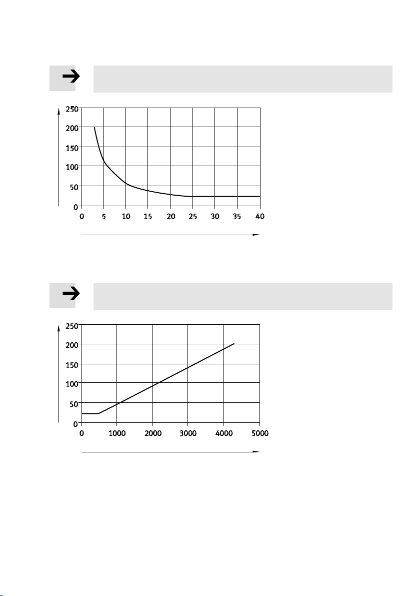
Hinweis
Verwenden Sie das folgende Diagramm bei bekanntem Laststrom.
[ms]
WCDT
T
I
[mA]
Last
Fig. 7 Interne Reaktionszeit in Abhängigkeit des Mindest-Laststroms
Hinweis
Verwenden Sie das folgende Diagramm bei bekanntem Lastwiderstand.
[ms]
WCDT
T
R
[Ohm]
Last
Fig. 8 Interne Reaktionszeit in Abhängigkeit der ohm'schen Mindestlast
Festo – CPX-FVDA-P2-Z6 – 2018-02a Deutsch 29
Page 30
CPX-FVDA-P2
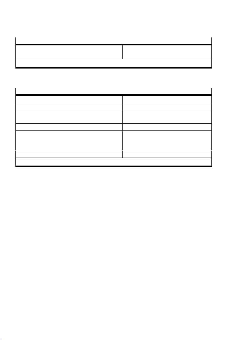
Abweichende Sicherheitskennwerte bei ausgeschalteten Testpulsen
Min. Anforderungsrate für jeden Ausgangs
[1/Tag] 1
1)
kanal (CH0, CH1, CH2)
1)
Mit Ausnahme der hier genannten Werte behalten die Sicherheitskennwerte ihre Gültigkeit.
Tab. 11 Abweichende Sicherheitskennwerte bei ausgeschalteten Testpulsen
Weitere Kennwerte
Umgebungstemperatur im Betrieb [°C] –5 … +50
Umgebungstemperatur bei der Lagerung [°C] –20 … +70
Relative Luftfeuchtigkeit (nicht konden
[%] 5 … 90
sierend)
Schutzart nach EN 60529 abhängig vom Anschlussblock
Elektromagnetische Verträglichkeit
è Konformitätserklärung (www.festo.com)
– Störaussendung
– Störfestigkeit
UL-Zertifizierung c UL us - Recognized (OL)
1)
è Beschreibung P.BE-CPX-FVDA-P2-... „Technische Daten der Anschlussblöcke“
Tab. 12 Weitere Kennwerte
1)
30 Festo – CPX-FVDA-P2-Z6 – 2018-02a Deutsch
Page 31

CPX-FVDA-P2
English – Output module CPX-FVDA-P2
Table of contents
1 Safety instructions 32........................................................
1.1 Intended use 33.............................................................
1.2 Rules for product configuration 34..............................................
1.3 Foreseeable misuse 36.......................................................
1.4 Attainable safety level 37.....................................................
1.5 Common cause failures (CCF) 37................................................
1.6 Requirements for product use 38...............................................
1.7 Technical prerequisites 38.....................................................
1.8 Training of qualified personnel 39...............................................
1.9 Transport and storage conditions 39.............................................
1.10 Service 39.................................................................
1.11 Range of application and certifications 40........................................
2 Product identification 41......................................................
3 Connection and display components 43..........................................
3.1 Design of the output module 43................................................
4 Installation 44..............................................................
4.1 Setting the PROFIsafe address 45...............................................
4.2 Dismounting the electronics module 46..........................................
4.3 Mounting the electronics module 47.............................................
4.4 Pin allocation 48.............................................................
5 Commissioning 50...........................................................
5.1 Start behaviour of the output module 50.........................................
6 Service, repair, disposal 52...................................................
7 Technical data 53............................................................
Festo – CPX-FVDA-P2-Z6 – 2018-02a English 31
Page 32
CPX-FVDA-P2
1 Safety instructions
Warning
Nonobservance of safety regulations can result in death, serious injuries or major
material damage.
Always follow the safety instructions.
Note
Electronics modules include electrostatically sensitive devices.
Incorrect handling can cause damage to the electronics modules.
Observe the handling specifications for electrostatically sensitive devices.
Discharge static electricity from your body before assembling or disassembling
modules to protect the modules.
Note
To ensure compliance with the intended use:
Each output channel that is in use must be switched at least once a week.
If test pulses are switched off:
Each output that is in use must be switched at least once a day.
Note
To ensure compliance with the safety level:
Each output channel that is in use must be switched on for more than 1 minute at
least once every 8 operating hours.
The operating time begins when the output module is first switched on.
Note
Use a maximum of 2 output channels in a common safety pilot circuit.
Observe the regulations for providing voltage (protective extra-low voltage, PELV)
to CPX terminals in the CPX system description P.BECPXSYS….
32 Festo – CPX-FVDA-P2-Z6 – 2018-02a English
Page 33
CPX-FVDA-P2
1.1 Intended use
The output module CPX-FVDA-P2 is used correctly as a shut-off module for the safe shutdown of
connected consumers (safety function) if the following condition is met:
– The connected consumers go into a safe state when the safety shutdown takes place.
The safety function is achieved through dual-channel, P- and M-side disconnection of the following load
voltage supplies of the CPX terminal:
– Load voltage supply for U
used to supply valve terminal pneumatic modules in the CPX terminal fitted on the right-hand side.
– Two outputs (output channel CH1 and CH2 of the module) provided through the connection
technology of the module, also supplied via U
valves of the CPX terminal (output channel CH0 of the module). This is
VAL
.
VAL
In addition, the unswitched load voltage supply U
is made available through the connection
VAL
technology of the module as operating voltage for the external components (24 V DC auxiliary supply).
The output channels of the CPX-FVDA-P2 each form a safety circuit with their connected consumers.
The output module CPX-FVDA-P2 is a product with safety-relevant functions and is intended for
installation in machines or automation systems and for use as follows:
– in excellent technical condition
– in its original condition, without unauthorised modifications
– only in the configurations named in the description P.BECPXFVDAP2...
– within the product limits defined by the technical data (è Chapter 7)
– in an industrial environment
Note
Note that the safety limits of the output module are also its physical limits.
Festo – CPX-FVDA-P2-Z6 – 2018-02a English 33
Page 34
CPX-FVDA-P2
1.2 Rules for product configuration
– Operation of the output module CPX-FVDA-P2 is permissible only in CPX terminals from Festo of the
variant CPX-M-....
– Comply with all technical operating limits (è Technical data).
Otherwise, operative malfunctions can occur.
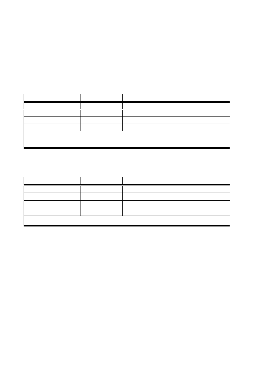
– Operation of the CPX-FVDA-P2 is permissible only in combination with the following
PROFIsafe-capable CPX bus nodes (è bus node rating plate):
Bus node From revision Network protocol
CPX-FB13
CPX-FB33
CPX-FB34
CPX-FB35
1)
2)
Tab. 1 Permissible PROFIsafe-capable CPX bus nodes
– Operation of the CPX-FVDA-P2 within CPX valve terminals is only permissible with the following valve
types:
Valve terminal Type Valve types
MPASFBVI 32 MPA1, MPA2 on VMPA…FBEMG…
MPAFFBVI 33 MPAF1, MPAF2 on VMPA…FBEMG…
VTSA-FB-VI 44 All up to width of 52 mm
VTSA-F-FBVI 45 All up to width of 52 mm
1)
Tab. 2 Permissible valve types
1)
2)
2)
2)
30 PROFIBUS
21 PROFINET IO
21 PROFINET IO
21 PROFINET IO
èDescription P.BE-CPX-FB13...
èDescription P.BE-CPX-PNIO...
èMalfunctions may occur if the resultant current is exceeded.
1)
1)
1)
1)
– Operation of shut-off groups within CPX valve terminals is only allowed in conjunction with permiss
ible pneumatics (è Description of the respective valve terminal).
34 Festo – CPX-FVDA-P2-Z6 – 2018-02a English
Page 35
CPX-FVDA-P2
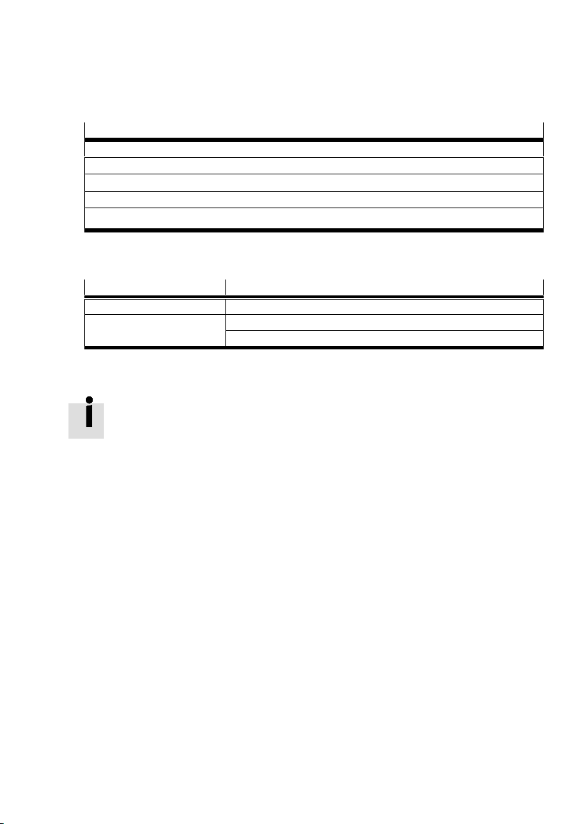
– Operation of shut-off groups in CPX terminals in the Remote I/O operating mode is only allowed
with the following approved output modules:
Output module
1)
CPX-4DA
1)
CPX-8DA
CPX-8DA-H
CPX-8DE-8DA
1)
1)
1)
èMalfunctions may occur if the resultant current is exceeded.
Tab. 3 Permissible output modules
– Only the following components are permitted when assembling the CPX-FVDA-P2:
Component Type
Interlinking block CPX-M-GE-EV-FVO
Connection block CPX-M-AB-4-M12X2-5POL
CPX-AB-8-KL-4POL
Tab. 4 Permissible components
Further information about the supported product versions of CPX can be found in the
description P.BECPXFVDAP2... .
Detailed information about the product, the supported product versions and required
software versions as well as the permissible components of the CPX terminal can be
found in the CPX system description P.BE-CPX-SYS-... (è www.festo.com/pk).
Information about permissible configurations of the CPX terminal in combination with the
output module can be found in the catalogue (è www.festo.com/catalogue).
Festo – CPX-FVDA-P2-Z6 – 2018-02a English 35
Page 36
CPX-FVDA-P2
1.3 Foreseeable misuse
The following examples of foreseeable misuse are among those not approved as intended use:
– use outdoors
– use in non-industrial areas
– use outside the limits of the product defined in the technical data
– unauthorised modifications
– use in combination with consumers where switching off can result in hazardous movements or
conditions
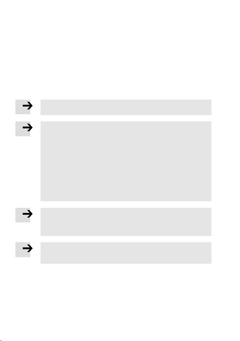
Note
The use of connection and interlinking blocks that are not specified is not permissible.
Note
In the following cases, the use of the output module CPX-FVDA-P2 for formation of
safety circuits is not permissible:
– in a CPX terminal equipped with CPX-FEC or CPX-CEC
– in a CPX terminal with shut-off groups containing output modules other than those
permitted
– in a CPX terminal of variant P
– in a CPX terminal with a connected valve terminal which is equipped with valve types
other than the following: VTSA, MPA-S, MPA-F (è Tab. 2)
– in a CPX terminal with a connected valve terminal where VPPM are located in
switching groups with a safety shutdown function
– in impermissible switching configurations (èDescription P.BECPXFVDAP2...)
Note
The output module does not contain any wearing parts. Repairs are not allowed on the
output module CPX-FVDA-P2. This invalidates the certification of the output module.
Professional replacement of the electronics module by the user is permissible.
Note
In the event of damage caused by unauthorised manipulation or any use other than that
intended, the warranty is invalidated and the manufacturer is not liable for damages.
36 Festo – CPX-FVDA-P2-Z6 – 2018-02a English
Page 37

CPX-FVDA-P2
1.4 Attainable safety level
With the CPX-FVDA-P2, safety functions can be implemented up to:
– Safety integrity level SIL 3 in accordance with IEC 61508
– Performance level e, Cat. 3 in accordance with EN ISO 13849-1
– SIL Claim Limit SIL CL 3 in accordance with EN 62061.
The attainable safety level of the overall safety device depends on the other components used to
implement a safety function.
To maintain the safety level:
Test the functionality of the safety device at adequate intervals.
1.5 Common cause failures (CCF)
Common cause failures cause the loss of the safety function, since both channels (P and M) in
adual-channel system fail simultaneously.
Through the following measures, you ensure that common cause failures are avoided:
Observe operating voltage limits
Observe temperature range
Use a maximum of 2 output channels in a common safety pilot circuit
Additional measures for avoidance of common cause failures may result from the application.
Festo – CPX-FVDA-P2-Z6 – 2018-02a English 37
Page 38

CPX-FVDA-P2
1.6 Requirements for product use
Make this brief description available to the design engineer, installation technician and personnel
responsible for commissioning the machine or system in which this product is used.
Keep this brief description throughout the entire product lifecycle.
Make sure that the specifications of the documentation are always complied with.
Also comply with the documentation for the other components and modules (e.g. bus nodes,
pneumatics, etc.).
Take into consideration the legal regulations applicable for the location as well as:
– Regulations and standards
– Regulations of the testing organisations and insurers
– National specifications
Remove all transport packaging, such as foils, caps, cardboard. The material used in the packaging
has been specifically chosen for its recyclability (exception: oil paper = residual waste).
Mounting must be performed in a professionally correct manner. To maintain the IP degree of
protection:
– Screw the connection block on tight (è Mounting the electronics module).
– Mount cable entry and seals in a professionally correct manner.
– Seal unused ports with cover caps.
If the system had to be shut down for safety reasons such as an emergency stop, make sure the
safety controller monitors/controls all system restarts.
1.7 Technical prerequisites
General conditions for the correct and safe use of the product, which must be complied with at all
times:
Comply with the technical operating limits (è Technical data).
Only then is operation of the product ensured in accordance with the relevant safety regulations.
When connecting standard auxiliary components, also observe the specified limit values for
temperatures, electrical data and torques.
38 Festo – CPX-FVDA-P2-Z6 – 2018-02a English
Page 39
CPX-FVDA-P2
1.8 Training of qualified personnel
The device may only be commissioned by trained, qualified control and automation technology
personnel, who are familiar with:
– installation and operation of control systems
– the applicable regulations for operating safety-related systems
– the applicable regulations for accident prevention and occupational safety
– the documentation for the product
Note
Work on safety-related systems may only be carried out by qualified personnel trained
in safety engineering.
1.9 Transport and storage conditions
Protect the product during transport and storage from excessive stress factors, such as:
– mechanical loads
– excessive temperatures
– moisture
– aggressive atmospheres
Store and transport the product in its original packaging.
The original packaging offers sufficient protection from typical stresses.
1.10 Service
Please consult your local Festo repair service if you have any technical problems.
Festo – CPX-FVDA-P2-Z6 – 2018-02a English 39
Page 40
CPX-FVDA-P2
1.11 Range of application and certifications
This product is a safety device as defined in the EU Machinery Directive and carries the CE marking.
Standards and test values, which the product must comply with and fulfil, can be found
inthe section “Technical data”. The product-relevant EC directives can be found in the
declaration of conformity. Certificates and the declaration of conformity for this product
can be found at www.festo.com.
Please note that compliance with the specified standards is limited to the output module
CPX-FVDA-P2. From the perspective of the output module, all disconnectable parts of
aCPXterminal or a valve terminal are treated as an external load.
Certain configurations of the product have been certified by Underwriters Laboratories Inc. (UL) for the
USA and Canada.
These configurations bear the following mark:
UL Recognized Component Mark for Canada and the United States
Only for connection to a NEC Class 2 supply.
Raccorder uniquement à un circuit de Classe 2.
Note
Observe the following if the UL requirements are to be complied with in your
application:
– Regulations for complying with the UL certification can be found in the separate
UL-specific special documentation.
The relevant technical data in that documentation also apply with priority if they do
not influence the safety characteristic values in an impermissible manner.
– The technical data in this documentation may show values deviating from this.
40 Festo – CPX-FVDA-P2-Z6 – 2018-02a English
Page 41
CPX-FVDA-P2
2 Product identification
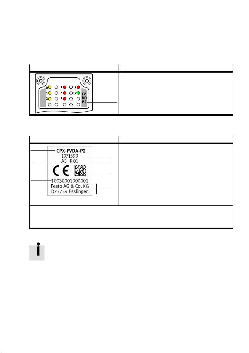
The module identifier and product rating plate serve to identify the product.
The module identifier can be seen through the transparent cover of the connection block.
Module identifier
Tab. 5 Module identifier of the output module CPX-FVDA-P2
The rating plate of the electronics module CPX-FVDA-P2 (è Fig. 1 7 ) shows the following information:
Rating plate (example) Meaning
1
7
6
1)
Part number of the electronic module CPX-FVDA-P2
2)
Permits traceability of the product.
3)
è Description P.BE-CPX-FVDA-P2-…
Tab. 6 Rating plate of the electronics module CPX-FVDA-P2
Meaning
– Module identifier 1 : FVDOP2
(F=Safety; V=Valves;
D=Digital; O=Outputs;
P=PROFIsafe; 2=Variant)
1
Rating plate
2
– Order reference 1
– Part number 2
3
– Revision code (here R01) 3
– Serial number represented as data matrix code 4
4
– Manufacturer and manufacturer’s address 5
– 14-character serial number 6
5
– Manufacturing period
(encoded, here A5 = May 2010) 7
1)
2)
2)
3)
You will find further information about this in the CPX system description
P.BE-CPX-SYS-... .
Festo – CPX-FVDA-P2-Z6 – 2018-02a English 41
Page 42
CPX-FVDA-P2
Before replacing a module, check whether the revision of the bus node corresponds to the require
ments of the module (è Tab. 1).
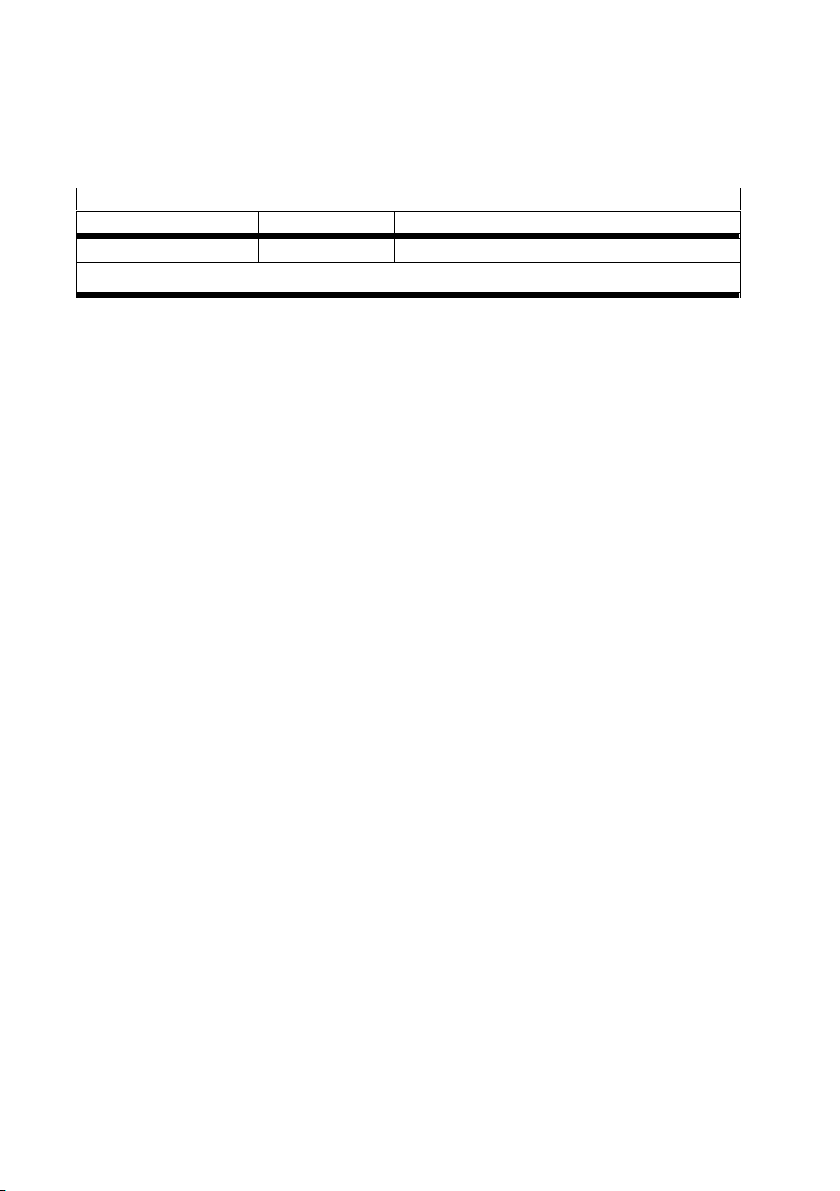
This brief description applies to the following product
Type Part number Revision
CPX-FVDA-P2 1971599 R0x
1)
x stands for a single digit from 1 to 9 (èTab. 6 3)
Tab. 7 Product described in this documentation
1)
42 Festo – CPX-FVDA-P2-Z6 – 2018-02a English
Page 43
CPX-FVDA-P2
3 Connection and display components
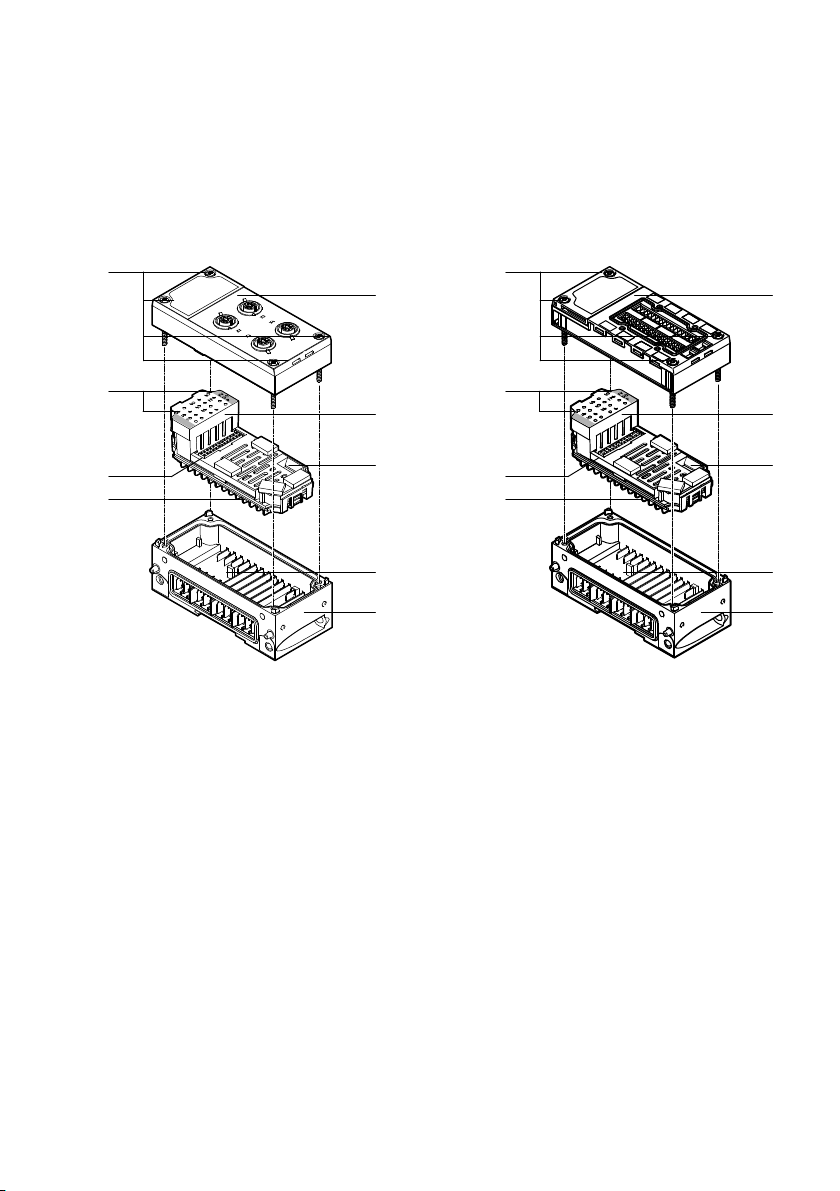
3.1 Design of the output module
aJ
1
9
8
3
4
7
5
6
1 Connection block CPX-M-AB-4-M12X2-5POL
2 Connection block CPX-AB-8-KL-4POL
3 Electronics module CPX-FVDA-P2
4 10-way DIL switch for PROFIsafe address
5 Mechanical coding
6 Interlinking block with contact rails
CPX-M-GE-EV-FVO
Fig. 1 Design of the output module CPX-FVDA-P2
aJ
9
8
7
7 Rating plate (underneath)
8 Electrical plug connection between
electronics module and connection block
9 LEDs of the electronics module
aJ Screws
2
3
4
5
6
Festo – CPX-FVDA-P2-Z6 – 2018-02a English 43
Page 44
CPX-FVDA-P2
4 Installation
Warning
For the electrical power supply, use only PELV circuits in accordance with
EN 60204-1 (protective extra-low voltage, PELV).
Also take into account the general requirements for PELV circuits in accordance with
EN 60204-1.
Only use power sources which guarantee reliable electrical isolation of the operating
voltage from the mains in accordance with EN 60204-1.
Ensure that defective cables are replaced immediately.
Through the use of PELV circuits, protection from electric shock (protection from direct and indirect
contact) is ensured in accordance with EN 60204-1 (refer to Electrical Equipment of Machines.
General Requirements).
Compliance with the input voltage limits of the module is also ensured.
Note
Electronics modules include electrostatically sensitive devices.
Observe the handling specifications for electrostatically sensitive devices.
Discharge static electricity from your body before assembling or disassembling
modules to protect the modules.
Note
The cross-circuit monitoring function monitors the device’s own circuits.
Ensure that cross-circuiting to other circuits is not possible using appropriate
installation measures.
Switch off the supply voltage before conducting any mounting or installation work.
Switch on the electrical supply voltage only when the product is completely mounted and all
installation work is finished.
44 Festo – CPX-FVDA-P2-Z6 – 2018-02a English
Page 45
CPX-FVDA-P2
4.1 Setting the PROFIsafe address
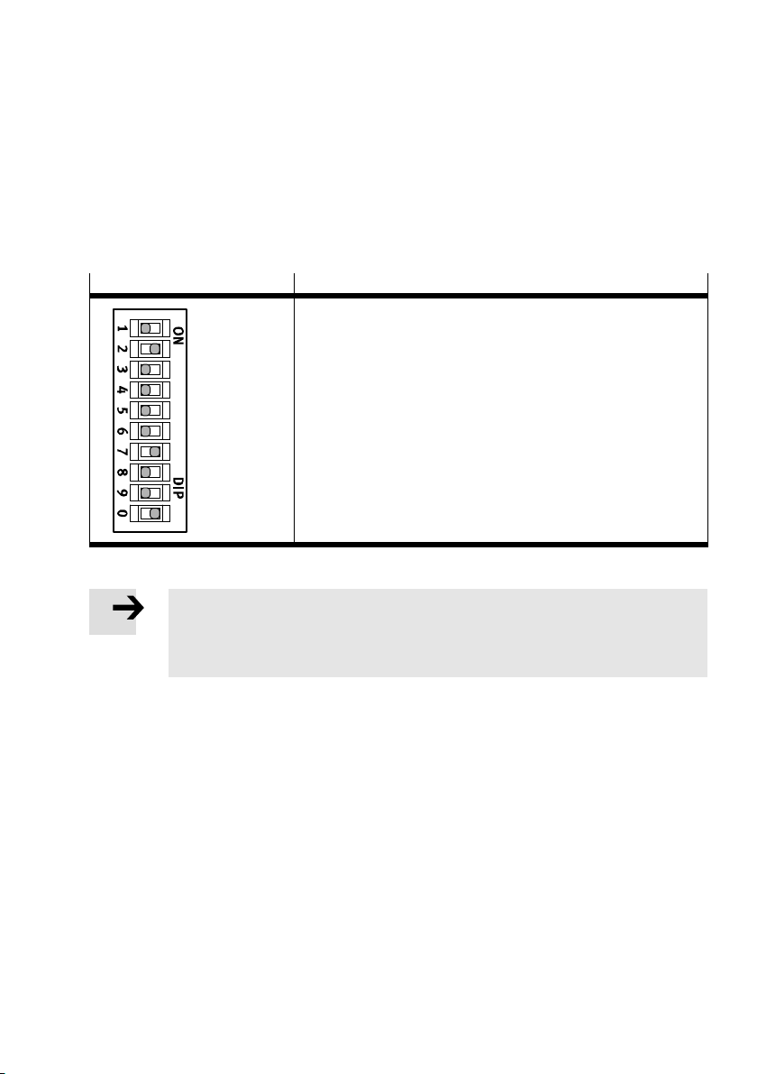
To allow communication via PROFIsafe, the correct PROFIsafe address must be set with binary coding
on the output module via the 10-way DIL switch (èFig. 2).
PROFIsafe addresses in the range from 1 to 1023 are permissible.
The 10-way DIL switch is located directly on the electronics module and can be set while the connection
block is not mounted.
10-way DIL switch Addressing example
2 + 64 + 512 = 578
1
2
4
8
16
32
64
128
256
512
Fig. 2 10-way DIL switch of the electronics module
Note
The DIL switch is a mechanically sensitive component due to its size.
To set it, use an appropriate, small blunt tool (e.g. watchmaker’s screwdriver) and
proceed very carefully.
1. Switch off the power supplies of the CPX terminal.
2. Remove the mounted connection block (è Fig. 1).
3. Carefully set the DIL switch.
4. Reinstall the connection block (è Mounting the electronics module).
Festo – CPX-FVDA-P2-Z6 – 2018-02a English 45
Page 46

CPX-FVDA-P2
4.2 Dismounting the electronics module
Note
Incorrect handling can damage the electronics module.
Never pull the electronics module out of the interlinking block when powered.
To avoid errors in mounting, both the interlinking block CPX-M-GE-EV-FVO and the
electronics module CPX-FVDA-P2 are mechanically coded.
The coding prevents a different module from being plugged into the interlinking block or
the module from being plugged into an incorrect interlinking block.
The plugs connected to the connection block can remain attached during dismounting of the
connection block.
To dismount:
1. Switch off the operating and load voltage supplies.
2. Unscrew the screws aJ and carefully lift off the connection block 1 / 2 (èFig. 1).
3. If necessary: pull the electronics module 2 carefully off the contact rails.
46 Festo – CPX-FVDA-P2-Z6 – 2018-02a English
Page 47
CPX-FVDA-P2
4.3 Mounting the electronics module
Note
Incorrect handling can damage the electronics module.
Never push the electronics module into the interlinking block when powered.
Note
Ensure that the interlinking block (èFig. 1) is clean and free of foreign matter,
especially on and near the contact rails.
Check the seals for damage in order to comply with the degree of protection
IP65/IP67.
Make sure that connecting surfaces are clean in order to optimise the sealing effect
and prevent contact errors.
Note
Use only screws with metric threads for the metal interlinking block
CPX-M-GE-EV-FVO.
To avoid damaging the threads, make sure the screws are inserted precisely and use
existing threads.
Tighten the screws using a hand-held screwdriver only.
Make sure that threaded fittings are free of any distortion or mechanical tension.
For modules and components ordered at a later date, observe the mounting
instructions in the documentation that comes with the products.
To mount:
1. Switch off the operating and load voltage supplies.
2. Align the electronics module 3 correctly and press it carefully into the interlinking block 6
(èFig. 1).
3. Check the seal and the sealing surfaces, align the connection block 1 / 2 and place it on the
electronics module 3.
4. Insert the screws aJ such that the existing threads can be used.
Tighten the screws by hand in diagonally opposite sequence.
Festo – CPX-FVDA-P2-Z6 – 2018-02a English 47
Page 48
CPX-FVDA-P2
4.4 Pin allocation
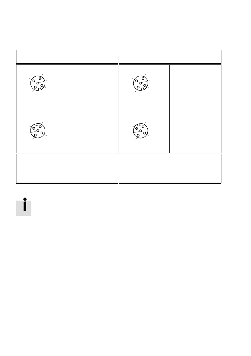
CPX-FVDA-P2 with connection block CPX-M-AB-4-M12X2-5POL
Pin allocation X1, X2 Pin allocation X3, X4
4
3
5
1
2
X1
Socket contact X1
1: 0 V CH1
2: +24 V CH1
1)
1)
3: F–DO(M) CH1
4: F–DO(P) CH1
2)
5: FE
4
3
2)
5
1
2
X3
Socket contact X3
1: n.c.
2: n.c.
3: n.c.
4: n.c.
5: FE
X2
2
1
5
3
4
Socket contact X2
1: 0 V CH2
2: +24 V CH2
1)
1)
3: F–DO(M) CH2
4: F–DO(P) CH2
2)
X4
2
1
2)
5
3
4
5: FE
FE = functional earth
n.c. = free (not connected)
1)
Unswitched voltage U
2)
All output voltages are likewise derived from the internal contact rail U
usable for supply of intelligent load systems (auxiliary supply)
VAL
Fig. 3 CPX-FVDA-P2 with connection block CPX-M-AB-4-M12X2-5POL
The metal thread of the connection block CPX-M-AB-4-M12X2-5POL is connected
internally with pin 5 (functional earth FE).
Socket contact X4
1: n.c.
2: n.c.
3: n.c.
4: n.c.
5: FE
.
VAL
48 Festo – CPX-FVDA-P2-Z6 – 2018-02a English
Page 49
CPX-FVDA-P2
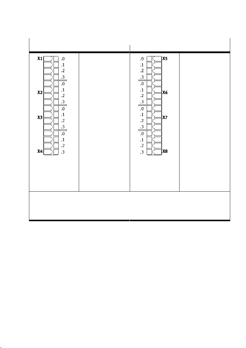
CPX-FVDA-P2 with connection block CPX-AB-8-KL-4POL
Pin allocation X1, X2, X3, X4 Pin allocation X5, X6, X7, X8
X1
0: 0 V CH1
1: F–DO (M) CH1
2: F–DO (P) CH1
1)
2)
2)
3: FE
X2
0: n.c.
1: n.c.
2: +24 V CH1
1)
3: FE
X3
0: 0 V CH2
1: F–DO (M) CH2
2: F–DO (P) CH2
1)
2)
2)
3: FE
X4
0: n.c.
1: n.c.
2: +24 V CH2
1)
3: FE
FE = functional earth
n.c. = free (not connected)
1)
Unswitched voltage U
2)
All output voltages are likewise derived from the internal contact rail U
usable for supply of intelligent load systems (auxiliary supply)
VAL
VAL
.
Fig. 4 CPX-FVDA-P2 with connection block CPX-AB-8-KL-4POL
X5
0: n.c.
1: n.c.
2: n.c.
3: FE
X6
0: n.c.
1: n.c.
2: n.c.
3: FE
X7
0: n.c.
1: n.c.
2: n.c.
3: FE
X8
0: n.c.
1: n.c.
2: n.c.
3: FE
Festo – CPX-FVDA-P2-Z6 – 2018-02a English 49
Page 50
CPX-FVDA-P2
5 Commissioning
5.1 Start behaviour of the output module
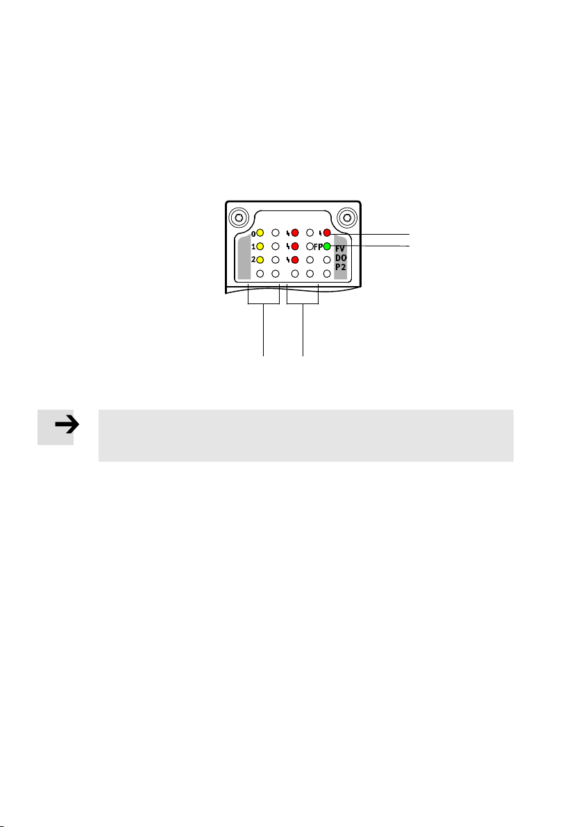
The following LEDs for on-site diagnostics are located under the transparent cover of the module:
1 Module error LED
(red)
2 FP LED (green) –
Failsafe Protocol
3 Channel error LED (red);
one for each output channel
4 Status LED (yellow);
one for each output channel
Fig. 5 LED indicator of the output module CPX-FVDA-P2
Note
The LED indicator of the module was not designed for safety purposes.
Do not evaluate these LEDs during safety-related activities.
4
3
1
2
When switching on the operating voltage supply U
approx. 500 ms.
When switching on load voltage supply U
The supplies can be switched on in any order as far as the output module is concerned.
If both power supplies are switched on simultaneously, the specified LEDs light up together.
The FP LED flashes until the output module is correctly parameterised by means of a PROFIsafe master.
After correct parameterisation, the FP LED lights up and the module is ready for operation.
50 Festo – CPX-FVDA-P2-Z6 – 2018-02a English
, channel error LEDs 3 light up for approx. 1 s.
VAL
, module error LED 1 lights up for
EL/SEN
Page 51
CPX-FVDA-P2
In the normal operating status, the following LEDs light up:
– FP LED – Failsafe Protocol 2 (green)
– Status LED 4 of the active output channels (yellow)
The status LEDs of inactive output channels and the module and channel error LEDs do not light up.
Note
Test the functionality of the safety device at adequate intervals.
Selecting the type of test and time intervals between the tests is the responsibility of
the operator.
The check is to be conducted such that flawless functioning of the safety device can be
verified in interaction with all components.
Additional information can be found in the CPX system description P.BE-CPX-SYS-…
Festo – CPX-FVDA-P2-Z6 – 2018-02a English 51
Page 52
CPX-FVDA-P2
6 Service, repair, disposal
The output module does not contain any components requiring service.
Note
The module does not contain any wearing parts. Repairs are not permitted.
This invalidates the certification of the output module.
The electronics module may be replaced by a duly trained technician.
Note
Always replace the output module in case of an internal defect.
Send the unmodified defective output module, including a description of the error
and the application, back to Festo for analysis.
Please contact your technical consultant to clarify how to return the module. In case of complaint or
repair, please specify the following: complaint type 2 in accordance with Festo VA 19.02.
For final disposal of the output module, please contact a certified waste management company for
electronic waste.
52 Festo – CPX-FVDA-P2-Z6 – 2018-02a English
Page 53
CPX-FVDA-P2
7 Technical data
General technical data of the CPX terminal
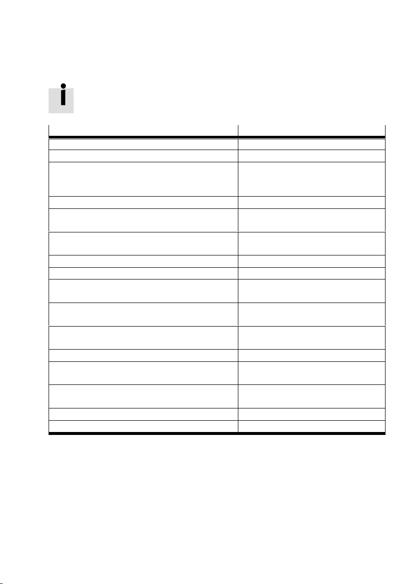
è CPX system description P.BE-CPX-SYS-...
Electrical characteristic values
CPX-FVDA-P2
Nominal operating voltage [V DC] 24
Permissible voltage fluctuations [%] –15 … +20
Operating voltage when tapping contact rail
24 V
VAL
and 0 V
(integrated reverse
VAL
[V DC] 20.4 … 28.8
polarity protection)
Residual ripple (within tol.) [Vss] 2
Voltage drop bypass time U
VAL
Intrinsic current consumption at nominal
operating voltage
Undervoltage monitoring U
Overvoltage monitoring U
Electrical isolation between V
(or 5 V CBUS) and V
VAL
VAL
EL,SEN
VAL
Electrical isolation between output channel
[ms] 2
[mA] typ. 65 for valves (from U
typ. 25 for electronics (from U
[V] < 19.5 for t > 250 ms
[V] > 29.5 for t > 250 ms
[V rms] Min. 500
Yes, with intermediate supply
(CH0, CH1, CH2) and internal bus
Electrical isolation between output channel
None
and output channel
Potential reference of the output channels U
Max. power supply CH0, CH1, CH2 (load
[A] 1.5
VAL
current per output channel)
Max. load current per unswitched voltage
U
(auxiliary supply)
VAL
[A] 2.5
Max. peak current per output channel [A] 5 for t < 30 ms
Max. resultant current per module [A] 5
VAL
)
EL/SEN
)
Festo – CPX-FVDA-P2-Z6 – 2018-02a English 53
Page 54
CPX-FVDA-P2
Electrical characteristic values CPX-FVDA-P2
Max. switching frequency of the output
[Hz] 1
channels
Max. voltage drop per output channel under
[V] 0.6
continuous load
Wire break detection (CH0, CH1, CH2) can be parameterised,
detection point I
approx. 50 mA
L
Max. cable length (CH1, CH2) [m] 200
Max. load capacity against FE [nF] 400
Max. load capacity P-M [μF] 22
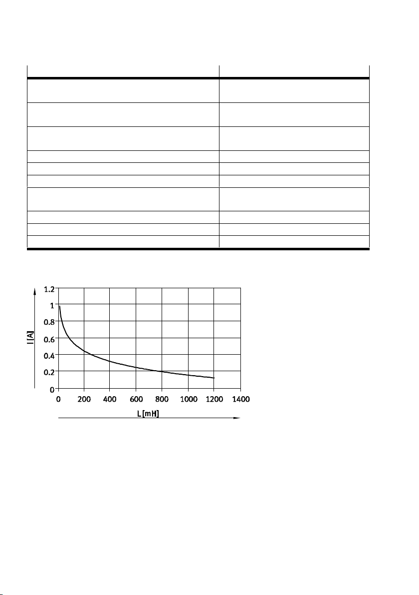
Max. load inductivity [mH] 1000 at 150 mA, 100 at 600 mA;
ècharacteristic curve Fig. 6
Fuse protection (short circuit) Integrated electronic fuse
Max. test pulse duration [µs] 300
Max. voltage drop during test pulse [V] 6
Tab. 8 Electrical characteristic values
Fig. 6 Maximum permissible load inductivity at the output channels
54 Festo – CPX-FVDA-P2-Z6 – 2018-02a English
Page 55
CPX-FVDA-P2
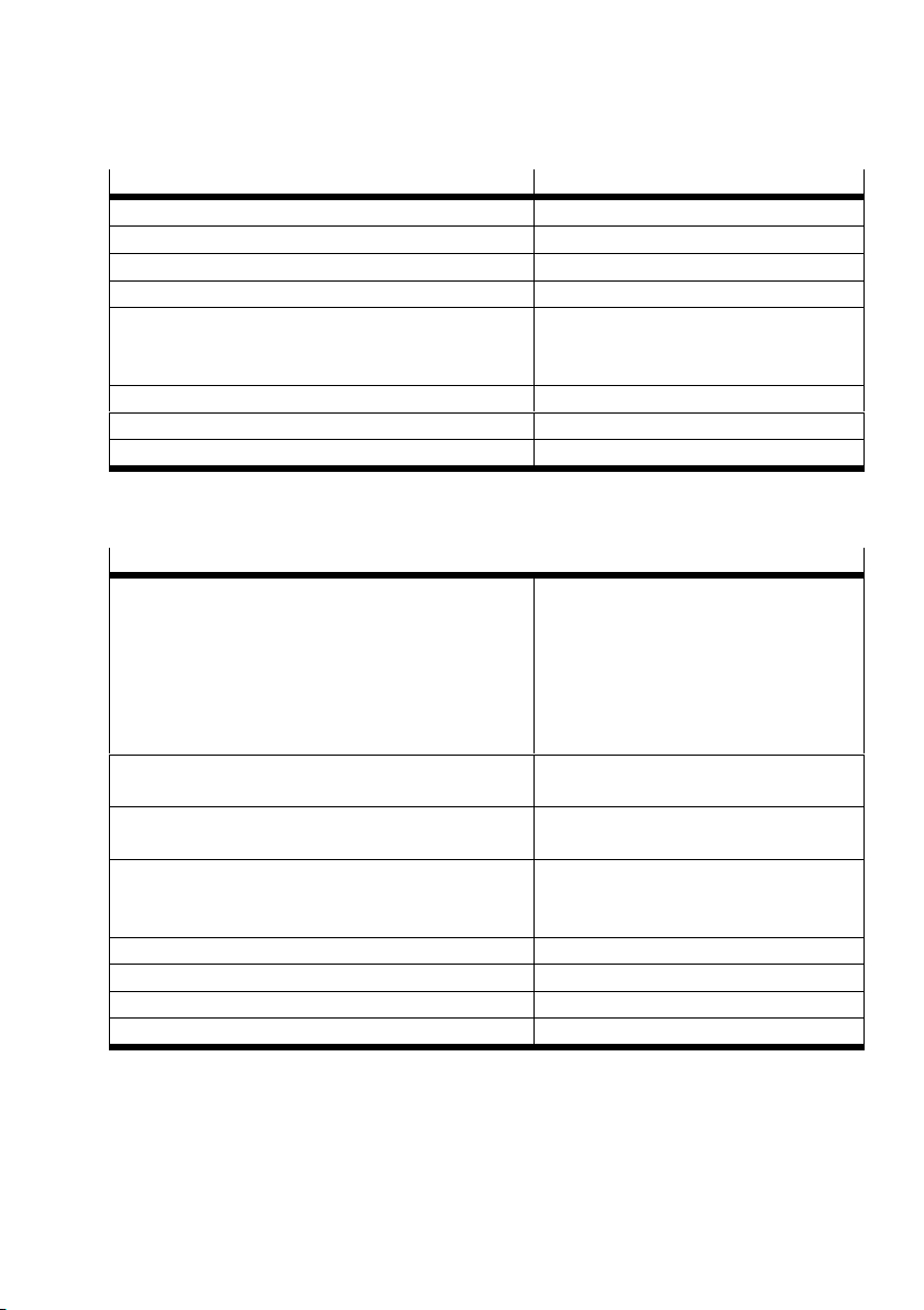
Functional characteristic values CPX-FVDA-P2
Module code 193d (C1h)
Sub-module code 8d (08h)
Compatible with fast start-up (FSU) Yes
Start-up time until module ready [s] < 2
Diagnostics of external channel errors – Periodic inspection for function
– Periodic inspection for external supply
– Periodic inspection for cross circuit
Response time for external channel errors [min] <1
Response time to switch off command (typ.) [ms] <10
Internal PROFIsafe processing time (T
) [ms] < 50
DAT
Tab. 9 Functional characteristic values
Safety characteristic values
1)
Safety function Safe shutdown of the output channels
– in accordance with IEC 61508
with SIL 3
– in accordance with EN ISO 13849
with Cat. 3, PL e
– in accordance with EN 62061
with SIL CL 3
Shutdown schema for each output
P and M switching
channel
Internal response time to switch off
command (T
) on output channel CH0
WCDT
Internal response time to switch off
command (T
) on output channels CH1
WCDT
[ms] < 23
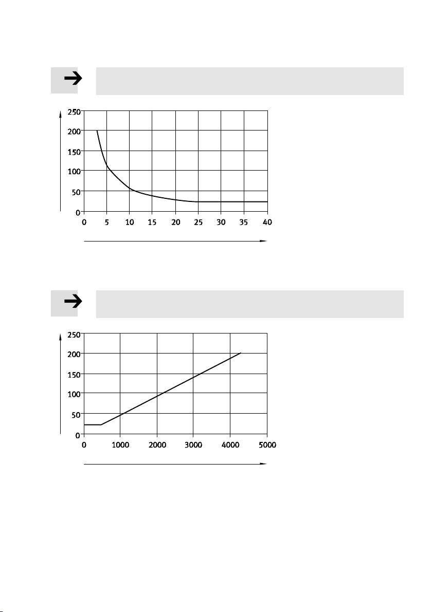
èLoad diagrams Fig. 7 and Fig. 8
and CH2 depending on minimum load
PROFIsafe watchdog time F_WD_TIME
Max. response time of safety function [ms] F_WD_TIME +T
WCDT
Max. cyclical demand rate [1/min] 1
Average time to dangerous failure (MTTFd) [years] >750
Festo – CPX-FVDA-P2-Z6 – 2018-02a English 55
Page 56
CPX-FVDA-P2
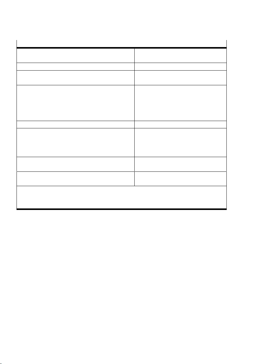
Safety characteristic values
Probability of a dangerous failure per hour
1)
[1/h] <1.0 x 10
–9
(PFHd)
Max. useful life [years] 20
Min. demand rate for each output channel
[1/week] 1
(CH0, CH1, CH2)
Measures to avoid common cause failures (CCF) – Observe operating voltage limits
– Observe temperature range
– Combine a maximum of 2 output
channels in a common safety pilot
circuit
Safety protocol PROFIsafe Profile Version2.4
2)
Type test The functional safety engineering of the
product has been certified by an
independent testing body, see EC-type
examination certificate è www.festo.com.
CE marking
In accordance with EU Machinery Directive
(è Declaration of conformity)
Certificate issuing authority TÜV(German Technical Control Board)
Rheinland 01/205/5294.01/18
1)
In order to guarantee the safety level, a minimum switch-on period of 1 minute must be ensured
every 8 operating hours for each output channel used.
2)
Profile for Safety Technology on PROFIBUS DP and PROFINET IO; Version 2.4, March 2007
Tab. 10 Safety characteristic values
56 Festo – CPX-FVDA-P2-Z6 – 2018-02a English
Page 57
CPX-FVDA-P2
Note
Use the following graph if the load current is known.
[ms]
WCDT
T
I
[mA]
load
Fig. 7 Internal response time as a function of the minimum load current
Note
Use the following graph if the load resistance is known.
[ms]
WCDT
T
R
[ohms]
load
Fig. 8 Internal response time as a function of the resistive minimum load
Festo – CPX-FVDA-P2-Z6 – 2018-02a English 57
Page 58
CPX-FVDA-P2
Deviating safety characteristic values when test pulses are switched off
Min. demand rate for each output channel
[1/day] 1
1)
(CH0, CH1, CH2)
1)
With the exception of the values specified here, the safety characteristic values retain
their validity.
Tab. 11 Deviating safety characteristic values when test pulses are switched off
Further characteristic values
Ambient operating temperature [°C] –5 … +50
Ambient temperature in storage [°C] –20 … +70
Relative humidity (non-condensing) [%] 5 … 90
Degree of protection to EN 60529 Dependent on the connection block
Electromagnetic compatibility
– Emitted interference
è Declaration of conformity
(www.festo.com)
– Immunity to interference
UL certification c UL us - Recognized (OL)
1)
è Description P.BE-CPX-FVDA-P2-... “Technical data of the connection blocks”
Tab. 12 Further characteristic values
1)
58 Festo – CPX-FVDA-P2-Z6 – 2018-02a English
Page 59

CPX-FVDA-P2
Festo – CPX-FVDA-P2-Z6 – 2018-02a English 59
Page 60

Weitergabe sowie Vervielfältigung dieses Dokuments, Verwertung
und Mitteilung seines Inhalts sind verboten, soweit nicht aus
drücklich gestattet. Zuwiderhandlungen verpflichten zu Schaden
ersatz. Alle Rechte sind für den Fall der Patent-, Gebrauchsmuster‐
oder Geschmacksmustereintragung vorbehalten.
Reproduction, distribution or sale of this document or communica
tion of its contents to others without express authorization is
prohibited. Offenders will be liable for damages. All rights re
served in the event that a patent, utility model or design patent is
registered.
Copyright:
Festo AG & Co. KG
Ruiter Straße 82
73734 Esslingen
Deutschland
Phone:
+49 711 347-0
Fax:
+49 711 347-2144
e-mail:
[email protected]
Internet:
www.festo.com
 Loading...