

Page 1
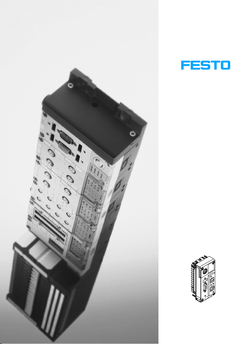
CPX terminal
Electronics manual
CPX−Front−End
Controller
Type CPX−FEC
Manual
538 475
en 0404NH
[677 480]
Page 2

Page 3

Contents and general instructions
Author U. Reimann. . . . . . . . . . . . . . . . . . . . . . . . . . . . . . . . .
Editor M. Holder. . . . . . . . . . . . . . .
. . . . . . . . . . . . . . . . . . . .
Edition en 0404NH. . . . . . . . . . . . . . . . . . . . . . . . . . . . .
Designation P.BE−CPX−FEC−EN. . . . . . . . . . . . . . . . . . . . . . . .
Order no. 538 475. . . . . . . . . . . . . . . . . . .
. . . . . . . . . . . . . .
. . . .
E (Festo AG&Co.KG, D73726 Esslingen, Federal Republic
of Germany, 2004)
Internet: http://www.festo.com
E−Mail: [email protected]
The reproduction, distribution and utilization of this
document as well as the communicaton of its contents to
others without express authorization is prohibited. Offenders
will be held liable for
the payment of damages. All rights
reserved in the event of the grant of a patent, utility module
or design.
Festo P.BE−CPX−FEC−E N en 0404NH
I
Page 4

Contents and general instructions
MODBUSt Registered trade mark of Schneider Automation
Microsoft Windowst Registered trade mark of Microsoft Corporation
Microsoft Internet Explo
t
rer
Registered trade mark of Microsoft Corporation
II
Festo P.BE−CPX−FEC−EN en 0404NH
Page 5

Contents and general instructions
Contents
Designated use VIII . . . . . . . . . . . . . . . . . . . . . . . . . . . . . . . . . . . . . . . . . . . . . . . . . . . . . . . .
Target group IX . . . . . . . . . . . . . . . . . . . . . . . . . . . . . . . . . . . . . . . . .
Service IX . . . . . . . . . . . . . . . . . . . . . . . . . . . . . . . .
Notes on the use of this manual X . . . . . . . . . . . . .
Important user instructions XI . . . . . . . . . . . . . . . . .
. . . . . . . . . . . . . . . . . . . . . . . . . . . . . . .
. . . . . . . . . . . . . . . . . . . . . . . . . . . . . .
. . . . . . . . . . . . . . . . . . . . . . . . . . . . .
. . . . . . . . . . . . . . . . .
1. System summary 1−1 . . . . . . . . . . . . . . . . . . .
1.1 Use the future of automation technology today 1−4 . . . . . . . . . . . . . . .
1.2 The operating modes of the CPX−FEC 1−5 . . . . . . . . . . . . . . . . . . . . . . . . . . . . . . .
1.2.1 Stand Alone 1−6 . . . .
1.2.2 Remote Controller 1−7 . . . . . . . .
1.2.3 Remote I/O 1−8 . . . . . . . . . . . . . . . . . .
1.2.4 Overview of the operating modes 1−9 . . . . . . . . . . . . . . . . . . .
1.3 Programming the CPX−FEC 1−10 . . . . . . . . . . . . . . . . . . . . . . . . . . . . . . . . . . . . . . . .
1.4 Meaning
1.4.1 Fault displays of the LEDs 1−12 . . .
1.5 Tutorial: Creating a project for the CPX−FEC with FST (Stand Alone) 1−15 . . . . . . .
2. Installatio
2.1 General notes on installation 2−4 . . . . . . . . . . . . . . . . . . . . . . . . . . . . . . . . . . . . . .
2.2 Setting the switches of the FEC 2−8 .
2.2.1 Rotary switch 2−8 . . . . . . . . . . . . .
2.2.2 DIL switches 2−9 . . . . . . . . . . . . . . . . . . .
2.3 Ethernet interface 2−11 . . . . . . . . . . . . . . . . . . . . . . .
2.3.1 Ethernet cable 2−11 . . . . . . . . . . . . . . . . . . . . . . . . .
2.4 Programming interface (RS232) 2−13 . . . . . . . . . . . . . . . . . . . . . . . . . . . . . .
2.4.1 Pin assignment 2−13 . . . . . . . . . . . . . . . . . . . . . . . . . . . . . . . . . . . . . . . . .
2.4.2 Connecting a programming
2.4.3 Connecting the Front End Display FED−50/90 2−17 . . . . . . . . . . . . . .
2.5 Service interface for handheld 2−18 . . . . . . . . . . . . . . . . . . . . . . . . . . . . . . . . . . . .
2.6 Compliance with protection class IP65/IP67 2−19 . . .
of the LED displays 1−11 . . . . . . . . . . . . . . . . . . . . . . . . . . . . . . . . . . . . . .
n 2−1 . . . . . . . . . . . . . . . . . . . . . . . . . . . . . . . . . . . . . . . . . . . . . . . . . . .
. . . . . . . . . . . . . . . . . . . . . . . . . . . . . . . . . . . . . . . .
. . . . . . . . . . . . . . . . . . . . . . . . . . . . . . . . . . .
. . . . . . . . . . . . . . . . . . . . . . . . . . . .
. . . . . . . .
. . . . . . . . . . . . . . . . . . . . . . . . . . . . . . .
. . . . . . . . . . . . . . . . . . . . . . . . . .
. . . . . . .
. . . . . . . . . . . . . . . . . . . . . . . . . . . . . .
. . . . . . . . . . . . . . . . . . . . . . . . . . . . . .
. . . . . . . . . . . . . . . . . . . . . . . . .
. . . . . . . . . . . . . . . . . . . . . . . .
. . . . . . . . . . . . . . . . .
. . . . .
PC 2−14 . . . . . . . . . . . . . . . . . . . . . . . . . . . . .
. . .
. . . . . . . . . . . . . . . . . . . . . .
Festo P.BE−CPX−FEC−E N en 0404NH
III
Page 6

Contents and general instructions
3. General operation (Stand Alone) 3−1 . . . . . . . . . . . . . . . . . . . . . . . . . . . . . . . . . .
3.1 Configuration 3−4 . . . . .
3.1.1 Create connection to CPX−FEC 3−4 . .
3.1.2 Creating a project 3−5 . . . . . . . . . . . . . . . . . . . .
. . . . . . . . . . . . . . . . . . . . . . . . . . . . . . . . . . . . . . . . . . . . .
. . . . . . . . . . . . . . . . . . . . . . . . . . .
. . . . . . . . . . . . . . . . . . .
3.1.3 Fast configuration by loading the actual configuration 3−8 . . . . . . . . . .
3.1.4 Manual configuration with the Hardware Configurator 3−10 . . . . . . . . .
3.2 Addressing 3−19 . . . . . . . . . . . . . . . . . . . . . . . . . . . . . . . . . . . . . . . . . . . . . . . .
. . . .
3.2.1 Default addressing 3−19 . . . . . . . . . . . . . . . . . . . . . . . . . . . . . . . . . . . . . .
3.2.2 Individual addressing 3−20 . . . . .
3.2.3 Addressing example 3−21 . . . . . . . . . . . . . . . . .
3.3 Parametrizing 3−27 . . . . . . . . . . . . . . . . . . . . . . . . . . . . . .
. . . . . . . . . . . . . . . . . . . . . . . . . . . . . . .
. . . . . . . . . . . . . . . . . . . .
. . . . . . . . . . . . . . . . . . . .
3.3.1 Parametrizing with the handheld 3−29 . . . . . . . . . . . . . . . . . . . . . . . . . .
3.3.2 Parametrizing with the Hardware Configurator of the FST 3−29 . . . . . . .
3.3.3 Parametrizing from a user program 3−34 . . . . . . . . . . . . . . . . . . . . . . . . .
3.3.4 Forcing 3−35 . . . .
3.3.5 Application example for the parametrizing 3−38 .
3.4 Programming the CPX−FEC 3−39 . . . . . . . . . . . . . . . . . . . . . . . . . . . . . .
. . . . . . . . . . . . . . . . . . . . . . . . . . . . . . . . . . . . . . . . . . . .
. . . . . . . . . . . . . . . . . .
. . . . . . . . . .
3.4.1 Overview of operands 3−40 . . . . . . . . . . . . . . . . . . . . . . . . . . . . . . . . . . . .
3.4.2 Overview
3.4.3 Overview of function modules for the CPX terminal 3−45 . . . . . .
of operations 3−41 . . . . . . . . . . . . . . . . . . . . . . . . . . . . . . . . . . .
. . . . . .
3.4.4 User programs 3−46 . . . . . . . . . . . . . . . . . . . . . . . . . . . . . . . . . . . . . . . . . .
3.4.5 Program example (STL) 3−50 . . . . . . . . . . . . . . . . . . . . . . . . . . . . . . . . . . .
3.5 Diagnosis 3−52 . . . . . . . . . . . .
3.5.1 Diagnosis with the controller LEDs RUN, STOP and ERROR 3−53
. . . . . . . . . . . . . . . . . . . . . . . . . . . . . . . . . . . . . . . . .
. . . . . .
3.5.2 Diagnosis with the Hardware Configurator 3−55 . . . . . . . . . . . . . . . . . . .
3.5.3 Diagnosis in the user program 3−59 . . . . . . . . . . . . . . . .
. . . . . . . . . . . . .
3.6 Access and control via CI commands 3−61 . . . . . . . . . . . . . . . . . . . . . . . . . . . . . . .
.
.
4. With the CPX terminal to the Ethernet 4−1 . . . . . . . . . . . . . . . . . . . . . . . . . . . . .
4.1 Ethernet in automation technology 4−4 . .
4.1.1 Why Ethernet? 4−4 . . . . . . . . . . . . . . . . . .
4.2 Basic principles of the Ethernet 4−5 . . . . . . . . . . . . . . . . . . . . .
. . . . . . . . . . . . . . . . . . . . . . . . . . . . . . .
. . . . . . . . . . . . . . . . . . . . . . . .
. . . . . . . . . . . . . . .
4.2.1 IP addressing in the Ethernet 4−6 . . . . . . . . . . . . . . . . . . . . . . . . . . . . . .
4.2.2 Data
IV
exchange on layers 1 to 4 4−9 . . . . . . . . . . . . . . . . . . . . . . . . . . . .
Festo P.BE−CPX−FEC−EN en 0404NH
Page 7

Contents and general instructions
4.2.3 Data exchange in the application layers 5 to 7 4−11 . . . . . . . . . . . . . . . .
4.3 Ethernet with CPX−FEC 4−13 . . . . . . . . . . . . . . . . . . . . . . .
. . . . . . . . . . . . . . . . . . . .
4.3.1 Connecting the CPX−FEC to the Ethernet 4−13 . . . . . . . . . . . . . . . . . . . . .
4.3.2 IP addressing of
4.3.3 HTTP 4−16 . . . . . . . . . . . . . . . . . .
4.3.4 TFTP, Telnet 4−17 . . . . . . . . . . . . . . . .
the CPX−FEC 4−13 . . . . . . . . . . . . . . . . . . . . . . . . . . . . . .
. . . . . . . . . . . . . . . . . . . . . . . . . . . . . . . .
. . . . . . . . . . . . . . . . . . . . . . . . . . . .
4.3.5 E−mails can be sent with the CPX−FEC (SMTP driver) 4−18 . . . . . . . . . . . .
4.3.6 Example of
a program for sending an e−mail 4−19 . . . . . . . . . . . . . . . . . .
4.4 The Webserver of the CPX−FEC 4−21 . . . . . . . . . . . . . . . . . . . . .
4.4.1 Possibilities and limits of the Webserver 4−21 . . . . . . . . . . . . . . . . . . . . .
4.4.2 Standard Web pages of the CPX−FEC 4−22 . . .
. . . . . . . . . . . . . . . . . . . . .
4.4.3 Creating own Web pages for the CPX−FEC 4−25 . . . . . . . . . . . . . . . . . . . .
4.4.4 Load files
into the Webserver 4−28 . . . . . . . . . . . . . . . . . . . . . . . . . . . . . .
. . . . . . . . . . . . . . .
5. Remote Controller mode 5−1 . . . . . . . . .
5.1 Remote Controller Ethernet 5−4 . . . . . . . . . . . . . . . .
5.1.1 Configuration 5−5 . . . . . . . . . . . . . . . . . . . . . . . . . .
. . . . . . . . . . . . . . . . . . . . . . . . . . . . . . . .
. . . . . . . . . . . . . . . . . . . . . . .
. . . . . . . . . . . . . . . . .
5.1.2 Operation as Remote Controller 5−7 . . . . . . . . . . . . . . . . . . . . . . . . . . . .
5.1.3 Diagnosis with
5.2 Remote Controller Field bus 5−13 . . . . . . . . . . . . . . . . . . . . . . . . . . . . . . . . . . .
the controller LEDs RUN, STOP, ERROR and TP 5−11 . . .
. . .
5.2.1 Configuration 5−15 . . . . . . . . . . . . . . . . . . . . . . . . . . . . . . . . . . . . . . . . . . .
5.2.2 Configuration example and communication
5.2.3 Parametrizing 5−21 . . . . . . . . . . . . . . . . . . . . . . . . . . . . . . . . . . . . . .
sequence 5−16 . . . . . . . . . .
. . . . .
5.2.4 Diagnosis 5−21 . . . . . . . . . . . . . . . . . . . . . . . . . . . . . . . . . . . . . . . . . . . . .
6. Remote I/O Ethernet 6−1 . . . . . . . . . . . . . . . . . . . . . . . . . . . . . . . . . . . . . . . . . .
6.1 General information 6−4 . . . . . . . . . . . . . . . . . . . . . . . . . . . . . . . . . . . . . . . . . . . . .
6.2 Modbus/TCP: Commands
and addressing 6−7 . . . . . . . . . . . . . . . . . . . . . . . . . . .
6.2.1 Modbus commands and address assignment 6−7 . . . . . . . . . . . . . . . .
6.2.2 CPX status information (group A) 6−8 . . . . . . . . . . . . . . . . . . . . . . . . . . .
6.2.3 Processing data (groups B and D) 6−10 . . . . . . . . . . . .
. . . . . . . . . . . . . .
6.2.4 Diagnostic memory (groups C and E) 6−24 . . . . . . . . . . . . . . . . . . . . . . . .
6.2.5 Objects (group F) 6−26 . . .
6.2.6 Addressing examples for Modbus/TCP 6−26 . . . . . . . . . .
Festo P.BE−CPX−FEC−E N en 0404NH
. . . . . . . . . . . . . . . . . . . . . . . . . . . . . . . . . . . . .
. . . . . . . . . . . .
.
. .
.
V
Page 8

Contents and general instructions
6.3 EasyIP 6−32 . . . . . . . . . . . . . . . . . . . . . . . . . . . . . . . . . . . . . . . . . . . . . . . . . . . . . . . .
6.4 Diagnosis 6−33 . . . . . . . . . . . . . . . . . . . . . . . . . . . . . . . . . . . . . . . . . . .
. . . . . . . . . .
6.4.1 Diagnosis with the control and Ethernet LEDs 6−33 . . . . . . . . . . . . . . . . .
A. Technical appendix A−1 . . . . . . . . . .
A.1 Technical specifications of the Front End Controller CPX−FEC A−3 . . . . . . . .
B. Drivers B−1 . . . . . . . . . . . . . . . . . . . . . . . . . . . . . . . . . . . . . . . . . .
B.1 Drivers B−3 . . . . . . . . . . . . . . . . . . . . . . . . . . . . . . . . . . . . .
. . . . . . . . . . . . . . . . . . . . . . . . . . . . . . . . . . .
. . . .
. . . . . . . . . . . . .
. . . . . . . . . . . . . . . . . . .
B.1.1 Drivers for the CPX−FEC (operating mode Remote Controller) B−3 . . . .
B.1.2 Drivers for the CPX−FEC (operating mode Remote I/O Ethernet) B−5 . .
C.Function modules C−1 . .
C.1 General function modules for the CPX−FEC C−3
C.1.1 Fault message C−13 . . . . . . . . . . . . . . . . . . . . . .
C.2 Modules for special functions of the CPX−FEC C−14 . . . . . . . . . . . . . . . . . . . . . . .
. . . . . . . . . . . . . . . . . . . . . . . . . . . . . . . . . . . . . . . . . . . .
. . . . . . . . . . . . . . . . . . . . . . . . . . .
. . . . . . . . . . . . . . . . . . . .
.
C.2.1 Modules for the SMTP driver (send e−mail) C−14 . . . . . . . . . . . . . . . . . . .
C.2.2 Fault codes C−17 . . . . . . . . . . . . . . . . . . . . . .
D. The Command Interpreter D−1 . . . . . . . . . . . . . . . . . . . .
D.1 The Command Interpreter (CI) D−3 . . . . . . . . . . . . . . . . . . . . . . . . . . .
. . . . . . . . . . . . . . . . . . . . . . .
. . . . . . . . . . . . . . . . . . . .
. . . . . . . . . .
D.1.1 Connection to a dialog device D−3 . . . . . . . . . . . . . . . . . . . . . . . . . . . . . .
D.1.2 Selecting the command interpreter (Login) D−4
. . . . . . . . . . . . . . . . . . .
D.1.3 Exiting the command interpreter D−6 . . . . . . . . . . . . . . . . . . . . . . . . . . .
D.1.4 CI
D.1.5 Displaying operands and statuses with
command D−6 . . . . . . . . . . . . . . . . . . . . . . . . . . . . . . . . . . . . . . . . . . . .
Display (D) D−10 . . . . . . . . . . . .
D.1.6 Changing operands with Modify (M) D−14 . . . . . . . . . . . . . . . . . . . . . . . .
D.1.7 Commands for program controller D−17 . . . .
. . . . . . . . . . . . . . . . . . . . . .
D.1.8 Commands for forcing inputs and outputs D−19 . . . . . . . . . . . . . . . . . . .
D.1.9 Initialising user memory D−21
D.1.10 Password D−22 . . . . . . . . . . . . . . . .
D.1.11 Driver−specific commands D−23 . . . . . . . . . . . . . . . . . .
D.1.12 Linking CI commands D−24 . . . . . . . . . . . . . . . . . . . . . . . . . . . . . . . . .
. . . . . . . . . . . . . . . . . . . . . . . . . . . . . . . . . .
. . . . . . . . . . . . . . . . . . . . . . . . . . . . . .
. . . . . . . . . . . . . . .
. . .
VI
Festo P.BE−CPX−FEC−EN en 0404NH
Page 9

Contents and general instructions
E.Index E−1 . . . . . . . . . . . . . . . . . . . . . . . . . . . . . . . . . . . . . . . . . . . . . . . . . . . . . . . . .
Festo P.BE−CPX−FEC−E N en 0404NH
VII
Page 10

Contents and general instructions
Designated use
The CPX−FEC (Front−End Controller) described in this manual
is intended exclusively for use as follows:
for controlling pneumatic and electric actuators (valves
for interrogating electric sensor signals through the input
communication via Ethernet
The CPX terminal may only be used as follows:
as intended in industrial installations.
and output modules)
modules
without any modifications by
the user. Only the conver
sions or modifications described in the documentation
supplied with the product are permitted.
in faultless technical condition.
The maximum values specified for pressures, temperatures,
electrical data, torques, etc. must not be exceeded.
If used together with additional commercially available com
ponents, such as sensors and actuators, the specified limits
pressures, temperatures, electrical data, torques etc.
for
must be observed.
Observe also the standards specified in the relevant chapters,
as well as national and local laws and technical regulations.
VIII
Festo P.BE−CPX−FEC−EN en 0404NH
Page 11

Contents and general instructions
Target group
This manual is intended exclusively for technicians trained in
control and automation technology who have experience in
installing, commissioning, programming and diagnosing
slaves on the Ethernet and the relevant field bus protocols.
Service
Please consult your local Festo repair service if you have any
technical problems.
Festo P.BE−CPX−FEC−E N en 0404NH
IX
Page 12
Contents and general instructions
Notes on the use of this manual
Please note
This manual refers to the following versions:
Hardware/software
CPX−FEC as from software status 31.03.2004
Festo Software Tools (FST) Version 4.1 or higher
CPX−FB06 Interbus
CPX−FB11 DeviceNet
CPX−FB13 PROFIBUS−DP 2)as from software status 26.02.2004
CPX−FB14 CANopen
CPX−FB23 CC−Link
1)
Software status (SW) see type plate
2)
For operating mode Remote Controller Field bus
2)
2)
2)
Version
as from software status 11.07.2003
2)
as from software status 06.10.2003
as from software status 22.08.2003
as from software status 07.08.2003
1)
Tab.0/1: Hardware and software states for this manual
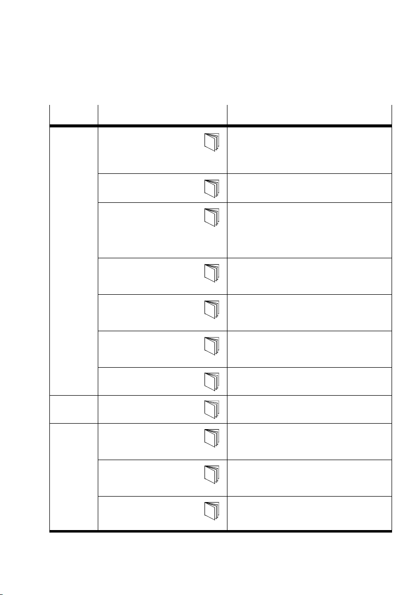
Note Tab.0/2 for further manuals on the CPX terminal.
X
Festo P.BE−CPX−FEC−EN en 0404NH
Page 13
Contents and general instructions
Important user instructions
Danger categories
This manual contains instructions on the possible dangers
which may occur if the product is not used correctly. These
instructions are marked (Warning, Caution, etc.), printed on a
shaded background and marked additionally with a picto
gram. A distinction is made between the following danger
warnings:
Warning
This means that failure to observe this instruction may
result in serious personal injury or damage to property.
Caution
This means that failure to observe this instruction may
result in personal injury or damage to property.
Festo P.BE−CPX−FEC−E N en 0404NH
Please note
This means that failure to observe this instruction may
result in damage to property.
The following pictogram marks passages in the text which
describe activities with electrostatically sensitive compo
nents.
Electrostatically sensitive components may be damaged if
they are not handled correctly.
XI
Page 14
Contents and general instructions
Marking special information
The following pictograms mark passages in the text contain
ing special information.
Pictograms
Information:
Recommendations, tips and references to other sources of
information.
Accessories:
Information on necessary or sensible accessories for the
Festo product.
Environment:
Information on environment−friendly use of Festo products.
XII
Text markings
· The bullet indicates activities which may be carried out in
any order.
1. Figures denote activities which must be carried out in the
numerical order specified.
Hyphens indicate general activities.
Festo P.BE−CPX−FEC−EN en 0404NH
Page 15
Contents and general instructions
Type Title Description
Electronics
manual
Software
package
System manual"
typeP.BE−CPX−SYS−...
CPX field bus node"
typeP.BE−CPX−FB...
CPX I/O modules"
type P.BE−CPX−EA−...
CPX analogue
I/Omodules"
typeP.BE−CPX−AX−...
CPX−CP interface"
type P.BE−CPX−CP−..
Handheld"
type P.BE−CPX−MMI−1−...
CPX−FEC"
type P.BE−CPX−FEC−...
FST" Programming in Statement List and Ladder
Overview of structure, components and
method of operation of CPX terminals
Installation and commissioning instructions as
well as basic principles of parameterisation
Instructions on fitting, installing, commission
ing and diagnosing the relevant field bus node
Notes on connection and instructions on fitting,
installing and commissioning input and output
modules of type CPX−..., the MPA pneumatic
modules as well as of MPA, CPA and Midi/Maxi
pneumatic interface
Notes on connection and instructions on fitting,
installing and commissioning CPX analogue I/O
modules
Instructions on commissioning and diagnosing
CPX terminals with the CP interface type
CPX−CP−4−FB
Instructions on commissioning and diagnosing
CPX terminals with the handheld type
CPX−MMI−1
Instructions on fitting, installing, commissio
ning and diagnos. the CPX Front−End Controller.
Diagram for the FEC
Manual
pneumatics
Valve terminals with
MPApneumatics"
type P.BE−MPA−...
Valve terminals with
CPApneumatics"
type P.BE−CPA−...
Valve terminals with
Midi/Maxi pneumatics"
type P.BE−MIDI/MAXI−03−...
Tab.0/2: Manuals on the CPX terminal
Festo P.BE−CPX−FEC−E N en 0404NH
Information on fitting, installing and commis
sioning MPA pneumatics (type 32)
Information on fitting, installing and commis
sioning CPA pneumatics (type 12)
Instructions on fitting, installing and commis
sioning Midi/Maxi pneumatics (type 03)
XIII
Page 16
Contents and general instructions
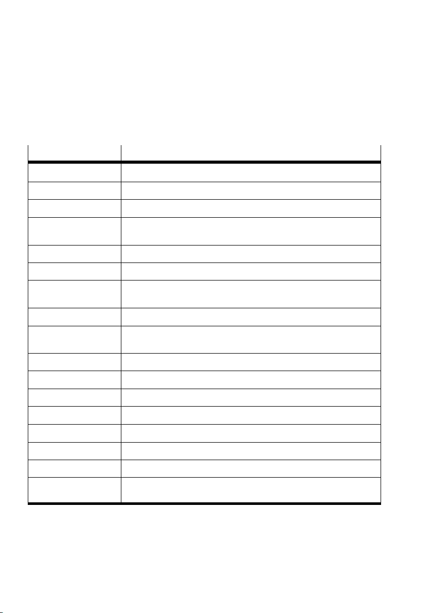
The following product−specific terms and abbreviations are
used in this manual:
Term/abbreviation
A0
h
AI Analogue input
AO Analogue output
CP modules Common term for the various modules which can be incorporated in a
CPX terminal Complete system consisting of CPX modules with or without pneumatics.
DI Digital input
DIL switch Dual−in−line switches usually consist of several switch elements with
DO Digital output
Field bus node Provides the connection to certain field buses. Transmits control signals
FW Flag word
Handheld / MMI Hand−operated device for commissioning and for servicing purposes
IB, IW Input byte, input word
I/O modules Common term for CPX modules which provide digital inputs and outputs.
I/Os Digital inputs and outputs
Meaning
Hexadecimal numbers are marked by a subscript h".
CPX terminal
which settings can be made.
to the connected modules and monitors their functioning.
OB, OW Output byte, output word
PLC/IPC Programmable logic controller/industrial PC
Pneumatic interface The pneumatic interface is the interface between the modular electrical
peripherals and the pneumatics.
Tab.0/3: Product−specific terms and abbreviations
XIV
Festo P.BE−CPX−FEC−EN en 0404NH
Page 17
Contents and general instructions
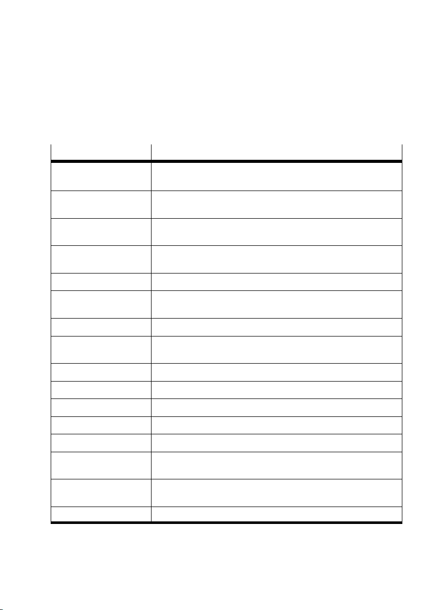
The following network−specific terms and abbreviations are
used in this manual:
Term/abbreviation
ARP Creates the relationship between the physical Ethernet address and
BOOTP Dynamic protocol for automatic assignment of IP addresses
DHCP Dynamic protocol for automatic assignment of IP addresses
EasyIP Protocol for the fast exchange of operands between Festo controllers
Ethernet Physical protocol and network for connecting various devices
FTP, TFTP Protocol for datatransmission via TCP/IP
HTTP Protocol for data transmission via TCP/IP (Hyper Text Transfer Protocol)
ICMP Exchange of fault and status information of the network
IP Protocol for addressing and delivering data (Internet Protocol)
ISO/OSI layer model Standardized model for data transmissions (7 layers)
MAC address Fixed assigned address for Ethernet device (Media Access Control)
Modbus/TCP Communication standard via TCP/IP in automation technology
TCP Protocol for data transport and protection (Transfer Control Protocol)
Meaning
the logical IP address (Address Resolution Protocol)
(Boot protocol, predecessor of DHCP)
(Dynamic Host Configuration Protocol)
(e.g. FEC Standard, PS1, etc.).
(File Transfer Protocol, Trivial File Transfer Protocol)
(Internet Control Message Protocol)
TCP/IP Combination of the protocols TCP and IP, the most−widely used protocol
in communication via Ethernet.
UDP Simplified protocol for data transport without test mechanisms
(User Datagram Protocol)
WWW World Wide Web
Tab.0/4: Network−specific terms and abbreviations
Festo P.BE−CPX−FEC−E N en 0404NH
XV
Page 18

System summary
Chapter 1
1−1Festo P.BE−CPX−FEC−E N en 0404NH
Page 19

1. System summary
Contents
1. System summary 1−1 . . . . . . . . . . . . . . . . . . . . . . . . . . . . . . . . . . . . . . . . . . . . . . .
1.1 Use
1.2 The operating modes of the CPX−FEC 1−5 . . . . . . . . . . . . . . .
1.3 Programming the CPX−FEC 1−10 . . . . . . . . . . . . . . . . . . .
1.4 Meaning of the LED displays 1−11 . . . . . . . . . . . . . . . . . . . . . . . . .
1.5 Tutorial: Creating a project for the CPX−FEC with FST (Stand Alone) 1−15 . . . . . . .
the future of automation technology today 1−4 . . . . . . . . . . . . . . . . . . . . . . .
. . . . . . . . . . . . . . . .
1.2.1 Stand Alone 1−6 . . . . . . . . . . . . . . . . . . . . . . . . . . . . . . . . .
1.2.2 Remote Controller 1−7 . . . . . . . . . . . . . . . . . . . . . . . . . . . . . . . . . . . . .
1.2.3 Remote I/O 1−8 . . . . . . . . . . . . . . . . . . . . . . . . . . . . . . . . . . . . . . . . . . . .
1.2.4 Overview of the
1.4.1 Fault displays of the LEDs 1−12 . . . . . . . . . . . . . . . . . . . . . . . . . . . . . . . .
operating modes 1−9 . . . . . . . . . . . . . . . . . . . . . . . . . .
. . . . . . . . . . . . . . . . . . . . .
. . . . . . . . . . .
. . . . . . . . . . . . .
. .
.
1−2
Festo P.BE−CPX−FEC−EN en 0404NH
Page 20

1. System summary
Contents of this chapter This chapter provides an overview of the three operating
modes of the CPX−FEC. A tutorial provides a first summary of
the most important configuration steps with the software
package FST 4.1.
Further information Detailed information on the CPX terminal and on the FST can
be found here:
manuals on the CPX terminal:
CPX system manual,
descriptions of the I/O modules, descriptions of the
fieldbus node
the FST manual (2 volumes, supplied with the FST
software)
text book Automation with FST" (supplied with the FST
software)
manuals on the pneumatics (MPA, CPA, CPV, Midi/Maxi)
Festo P.BE−CPX−FEC−E N en 0404NH
1−3
Page 21

1. System summary
1.1 Use the future of automation technology today
With the CPX−FEC, the CPX terminal offers today the technol
ogy of tomorrow for automation tasks. Here is an overview of
the possibilities which are offered:
The CPX−FEC can control a CPX terminal independently
(Stand Alone). Use the Festo Software Tool FST 4.1 with
the Hardware Configurator for commissioning, program
ming and diagnosis.
can control a CPX terminal and tell you via Ethernet
It
what is running. You can easily access current data via
your company’s network. (Remote Controller Ethernet)
It fits into your existing automation system without prob
lems: Let the CPX−FEC as a PLC control the CPX terminal
and at the same time communicate with
field bus (at present: PROFIBUS, Interbus, DeviceNet,
CANopen and CC−Link). (Remote Controller Field bus)
your existing
1−4
Control the CPX terminal straight away via Ethernet, the
CPX−FEC makes this possible: In the operating mode
Remote I/O Ethernet" the CPX terminal is a field bus
slave on the Ethernet.
A Webserver is incorporated in the CPX−FEC.
With a standard
Web Browser you can access current data. You can transfer
Web pages which you have created into the CPX−FEC in order
to perform more complex tasks from a self−created user inter
face level.
You can set up the CPX−FEC so that it sends e−mails when
previously defined events occur. This
can be e.g. a message
about a diagnostic case or the processing of a certain task.
Festo P.BE−CPX−FEC−EN en 0404NH
Page 22

1. System summary
1.2 The operating modes of the CPX−FEC
The CPX−FEC can be operated in various operating modes
depending on the demand:
Stand Alone
Remote Controller
Remote I/O
The operating mode can be set with DIL switch 1
(see section 2.2.2).
You can connect a handheld of type CPX−MMI to the CPX−FEC
in any operating mode. The handheld serves for fast prelimi
nary commissioning,
parametrizing and diagnosis.
Festo P.BE−CPX−FEC−EN en 0404NH
1−5
Page 23
1. System summary
1.2.1 Stand Alone
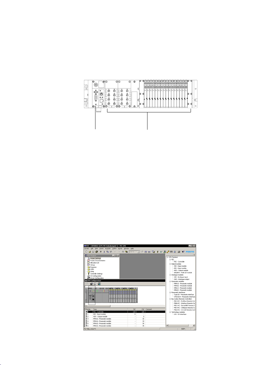
12
1 CPX−FEC
2 Controlled by the CPX−FEC
Fig.1/1: CPX terminal controlled by the CPX−FEC
Stand Alone
The CPX terminal is controlled independently by the
CPX−FEC. There is no communication connection to other
slaves.
1−6
Configure the CPX terminal with the FST software package
FST4.1 or higher. The programming or Ethernet interface
be used for the configuration.
Fig.1/2: Software package FST 4.1 for configuration
Festo P.BE−CPX−FEC−EN en 0404NH
can
Page 24
1. System summary
1.2.2 Remote Controller
Ethernet
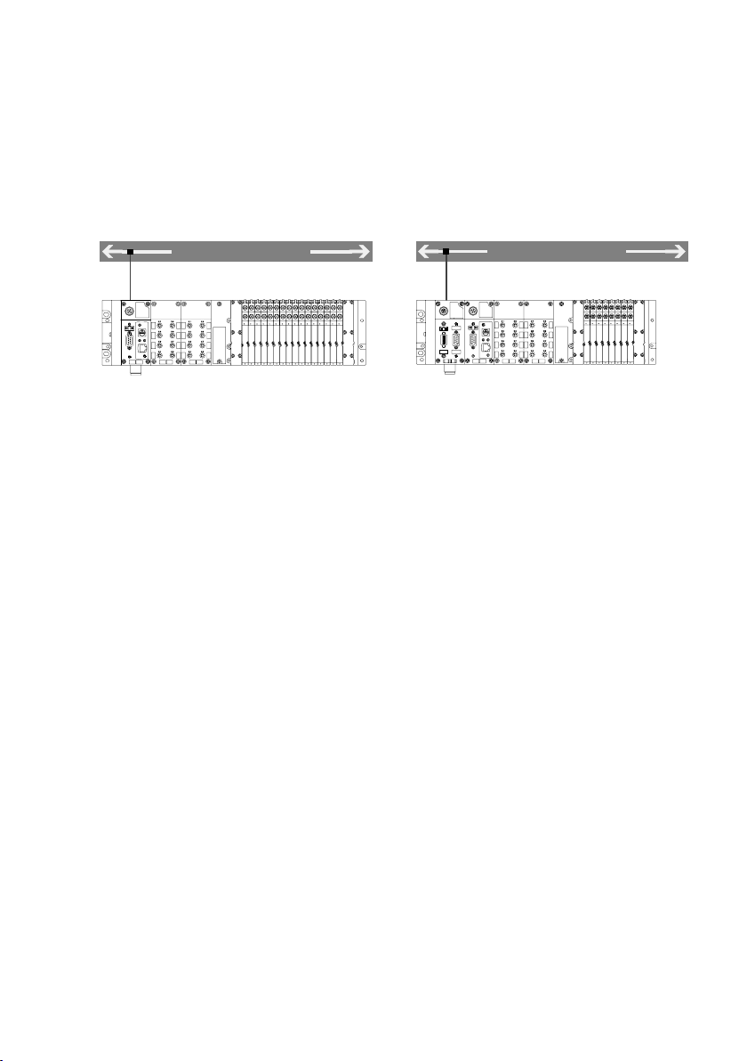
1 CPX terminal controlled by the
CPX−FEC, communication via Ethernet
In this operating mode the CPX terminal is controlled by the
CPX−FEC (as in Stand Alone), but there is also a communica
tion connection with a higher−order controller. Communica
tion can take place via Ethernet or via a field bus:
Remote Controller Ethernet
The CPX terminal is controlled by the CPX−FEC. The FEC also
communicates via Ethernet (Modbus TCP, EasyIP) with a
higher−order controller. You can use IT technology for the
controller, diagnosis and communication (e.g. Webserver,
e−mail, ...). An advantage of this operating mode is that you
only need to use one bus system.
Configure the CPX terminal with FST via the Ethernet inter
face.
Field bus
2 CPX terminal controlled by the
CPX−FEC, communication via field bus
(field bus node required)
Festo P.BE−CPX−FEC−EN en 0404NH
Remote Controller Field bus
The CPX terminal is controlled by the CPX−FEC. The FEC also
communicates via the
ler. A field bus node (with DIL switch position for Remote
Controller") must be installed in the CPX terminal for this
operating mode.
Configure the CPX terminal with FST.
field bus with a higher−order control
1−7
Page 25
1. System summary
1.2.3 Remote I/O
Ethernet
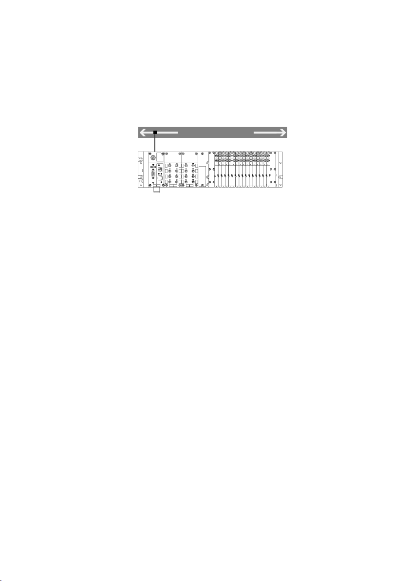
1 CPX terminal controlled via Ethernet
Remote I/O Ethernet
The CPX terminal is controlled by a higher−order controller
via Ethernet. The CPX−FEC has the function of an Ethernet
field bus slave. In this way you can combine your CPX ter
minal with
Schneider Electric).
You can use the integrated Webserver for control, diagnosis
and communication. An advantage of this operating mode is
that you only need to use one bus system.
existing Ethernet automation systems (e.g.
1−8
Festo P.BE−CPX−FEC−EN en 0404NH
Page 26
1. System summary
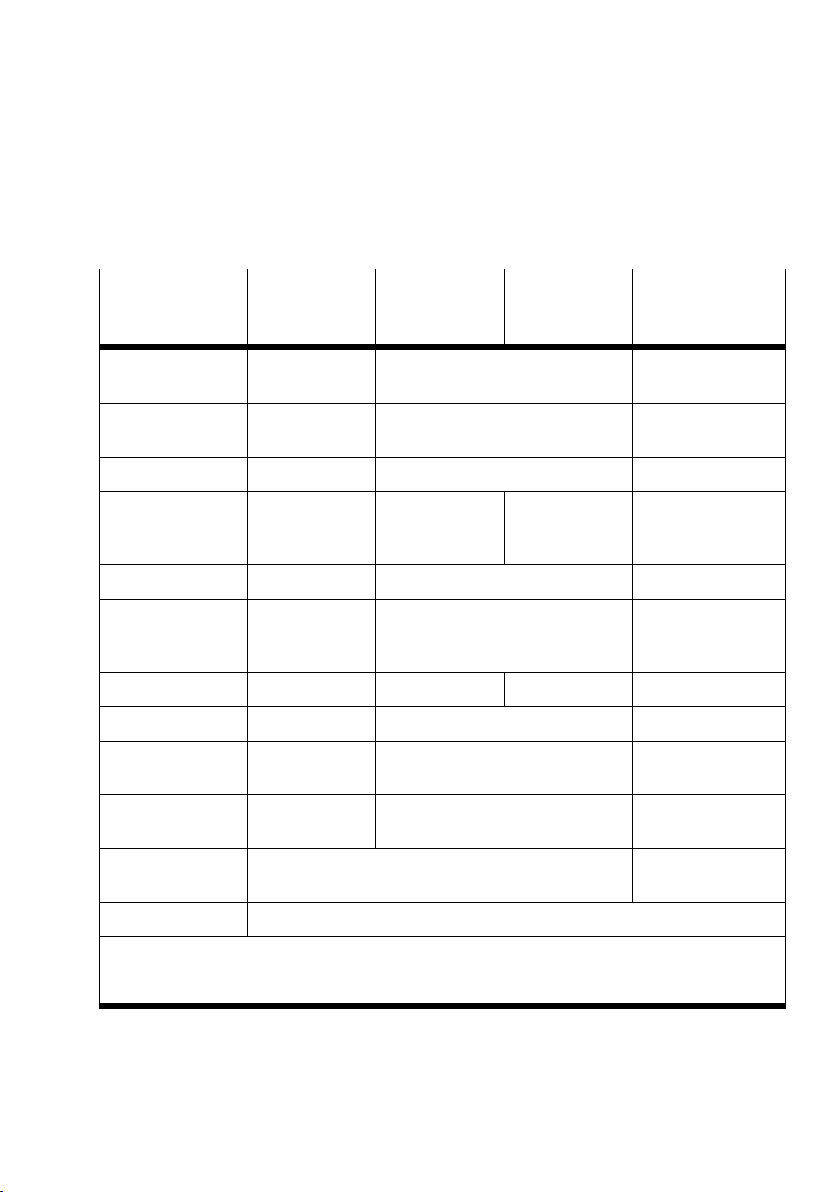
1.2.4 Overview of the operating modes
Stand Alone Remote
Controller
Ethernet
Function of the
CPX−FEC
CPX module
controlled by
PLC used Yes Yes No
Communication
with higher−order
controller
Webserver Possible Possible Possible
Configuration FST 4.1 or
Parametrizing with FST/Handheld FST/Handheld FST/Handheld Handheld/Modbus
Module code 208 208 210
Addressing Default (can be
Memory location 2)250 kB (PLC)
Controller Control and communication Ethernet slave
CPX−FEC CPX−FEC Higher−order
No Via Ethernet Via field bus
higher
modified)
550 kB (Webs.)
FST 4.1 or higher Higher−order
Default (can be modified) Specified
250 kB (PLC)
550 kB (Webserver)
Remote
Controller
Field bus
Remote I/O
controller
1)
Via Ethernet
controller (e.g. with
Schneider Unity)
800 kB (Webserver)
Switch position
DIL1
Handheld Can be connected to the CPX−FEC
1)
A field bus node in the operating mode Remote Controller" must also be installed here in the
CPX terminal.
2)
The Webserver can occupy free memory space in the PLC if extra memory space is required.
DIL 1.1: OFF
DIL 1.2: OFF
DIL 1.1: OFF
DIL 1.2: ON
Tab.1/1: Overview of the operating modes
Festo P.BE−CPX−FEC−EN en 0404NH
1−9
Page 27
1. System summary
1.3 Programming the CPX−FEC
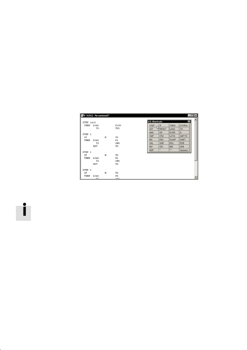
Use the software package FST 4.1 or higher in order to pro
gram the CPX−FEC. Programming is carried out in the lan
guages Statement List (STL) or Ladder Diagram (LDR).
Further information can be found in the relevant chapters for
the different operating modes.
1−10
Fig.1/3: Programming with FST 4.1
You can find detailed information on programming the CPX−
FEC in the following documentation:
the FST manual (supplied with the FST software)
the text book Automation with FST" (supplied with the
FST software).
Festo P.BE−CPX−FEC−EN en 0404NH
Page 28
1. System summary
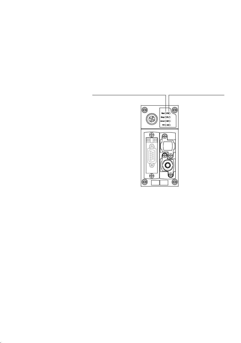
1.4 Meaning of the LED displays
The LEDs on the cover indicate the operating status of the
CPX−FEC and are arranged in two groups.
1 Control and
Ethernet LEDs
(see chapters 3, 5
and 6):
RUN
STOP
ERROR
TP
12
2 CPX−LEDs
(see next section):
PS: Power system
PL: Power load
SF: System fault
M: Modify
Fig.1/4: Two groups of the LEDs of the CPX−FEC
Festo P.BE−CPX−FEC−EN en 0404NH
1−11
Page 29
1. System summary
LED flashes
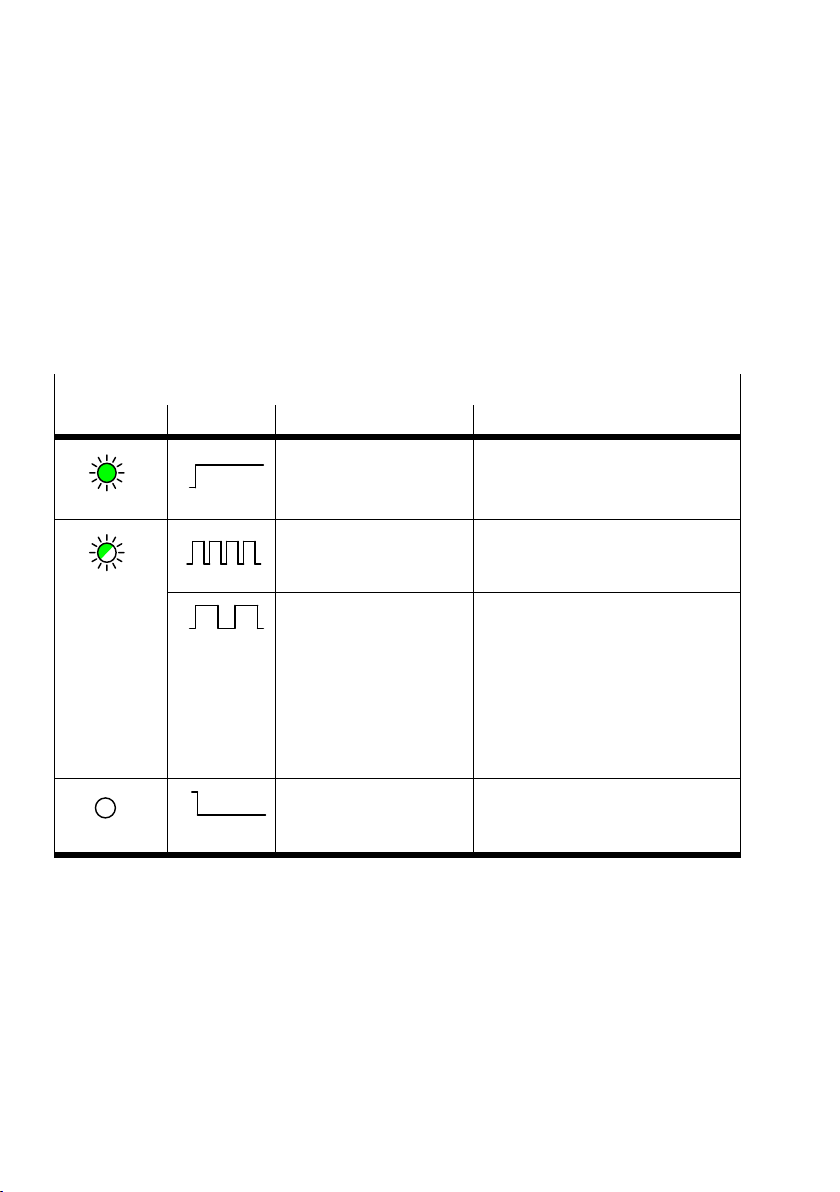
1.4.1 Fault displays of the LEDs
In the following only the general CPX−LEDs PS, PL, SF and M
are explained. Information on the controller and Ethernet
LEDs RUN, STOP, ERROR and TP can be found in chapters 3, 5
and 6.
PS (Power System) power sensor/log
ic supply
LED (green) Sequence Status Meaning/fault treatment
LED lights up
ON
OFF
ON
OFF
No fault Operating
voltage/sensor supply
applied
Operating voltage/sensor
supply outside the
Eliminate undervoltage
tolerance range
ON
OFF
Internal fuse for the
operating voltage/sensor
supply has responded.
1. Eliminate short circuit/overload on
module side.
2. Depending on the parametrizing of
the module (module parameter):
· The sensor supply voltage will
be switched on again automati
cally when the short circuit has
been eliminated (default)
· Power Off/On is necessary
ON
OFF
LED is out
The operating voltage/
sensor supply is not
applied
Check the operating voltage
connection of the electronics
Tab.1/2: Fault diagnosis with the LED PS
1−12
Festo P.BE−CPX−FEC−EN en 0404NH
Page 30
1. System summary
PL (Power Load) power load supply (outputs/valves)
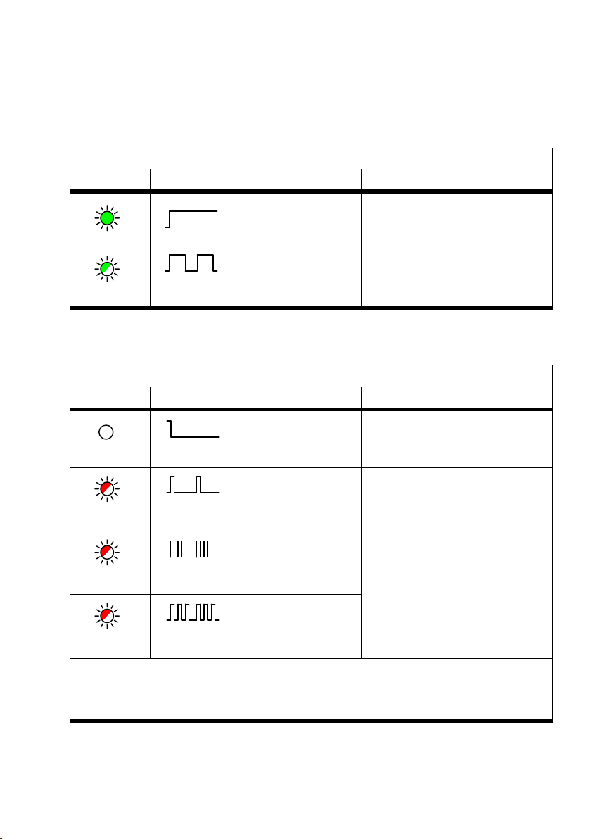
LED (green) Sequence Status Meaning/fault treatment
ON
OFF
No fault Load voltage
applied
None
LED lights up
ON
OFF
LED flashes
Load voltage at the system
supply or additional supply
outside the tolerance
range
Eliminate undervoltage
Tab.1/3: Fault diagnosis with the LED PL
SF (System Fail) system fault
LED (red) Sequence Status Meaning/fault treatment
ON
OFF
LED is out
ON
OFF
LED flashes
once
ON
OFF
LED flashes
twice
ON
OFF
LED flashes
three times
1)
The system fault LED flashes depending on the class of fault which has occurred.
Fault class 1 (simple fault): one flash, pause
Fault class 2 (fault): flash twice, pause
Fault class 3 (serious fault): flash three times, pause
No fault
Simple fault/information
(fault class 1)
Fault
(fault class 2)
Serious fault
(fault class 3)
See description of fault numbers in
the CPX system manual
Tab.1/4: Fault diagnosis with the LED SF
Festo P.BE−CPX−FEC−EN en 0404NH
1−13
Page 31
1. System summary
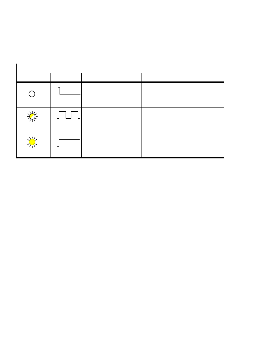
M (Modify) Force active
LED (yellow) Sequence Status Meaning/fault treatment
ON
OFF
None
LED is out
ON
OFF
Force is active The Force function is enabled
LED flashes
ON
OFF
The CPX−FEC has no parameter
LED lights up
Tab.1/5: Messages of the LED M
Information on the controller and Ethernet LEDs RUN, STOP,
ERROR and TP can be found in chapters 3...6.
(seesystem parameter Force mode;
function no. 4402).
System start", so that the status
LED lights up" does not exist with
the M−LED.
1−14
Festo P.BE−CPX−FEC−EN en 0404NH
Page 32
1. System summary
1.5 Tutorial: Creating a project for the CPX−FEC with FST (Stand Alone)
This tutorial presents the most important steps for commis
sioning a CPX terminal with FEC. The tutorial deals only with
the operating mode Stand Alone.
Read the detailed introduction in the following chapters and
in the FST manual.
Caution
If you have connected a CPX terminal to your PC for
configuration: Test projects and programs at first without
active actuators or without compressed air.
You will then avoid damage in the test phase.
1. Install your CPX terminal with CPX−FEC in accordance with
chapter 2 and set the rotary switch of the
2. Use the programming cable to connect the CPX−FEC to the
serial interface of your PC.
CPX−FEC to 0".
Festo P.BE−CPX−FEC−E N en 0404NH
3. Start the FST 4.1 and select [Extras] [Preferences...]
Communication" register: Use RS232"
Confirm with OK.
4. Select [Project] [New...] and assign a project name.
5. Select the CPX−FEC as controller in the window
ProjectSettings".
6. Open the Hardware Configurator with
a double click on
I/OConfiguration" in the project window.
7. Select Actual−Nominal−Comparison" in the context menu
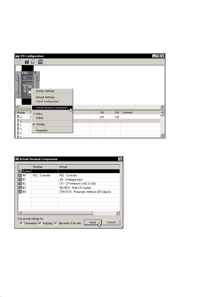
(right−hand mouse click) of the Hardware Configurator.
Accept the configuration by clicking on Apply".
1−15
Page 33
1. System summary
Fig.1/5: Carry out the actual−nominal comparison
Fig.1/6: Apply the actual−nominal comparison
1−16
Festo P.BE−CPX−FEC−EN en 0404NH
Page 34
1. System summary
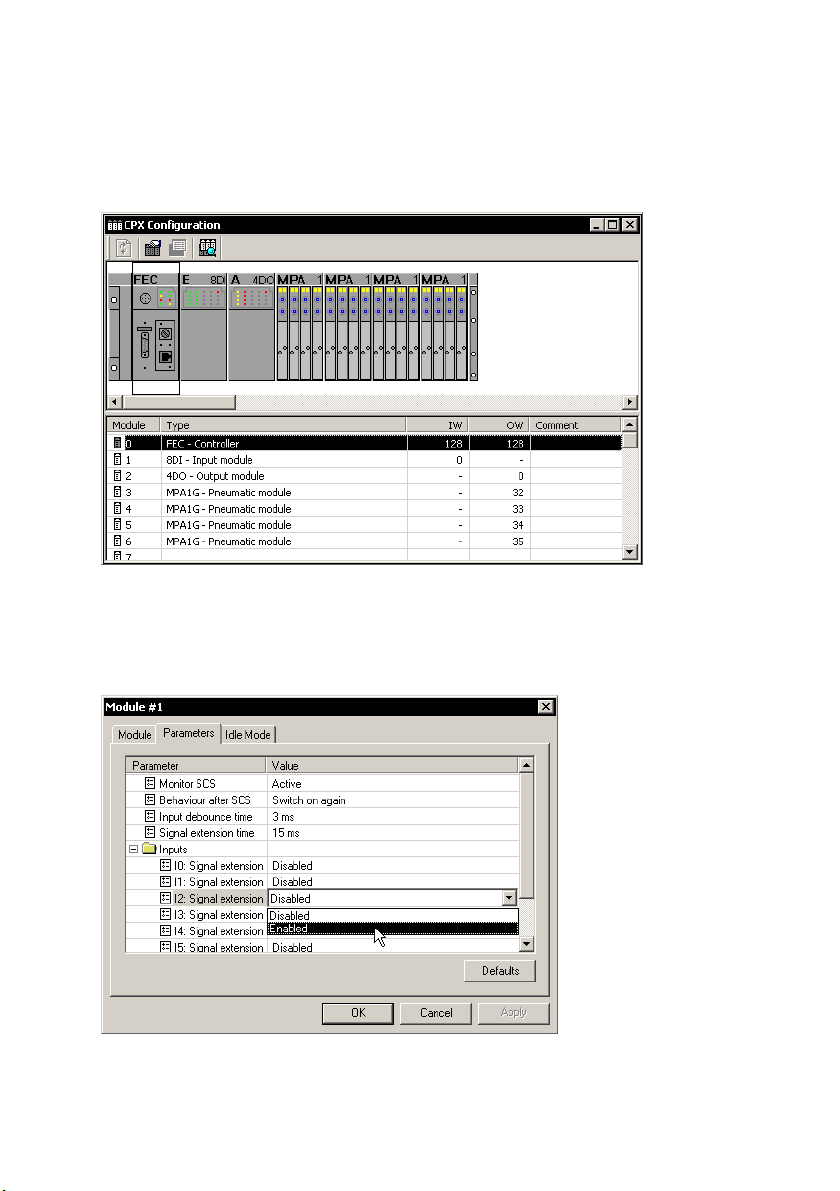
Fig.1/7: A configured CPX terminal
8. If necessary, parametrize the CPX system or individual
modules:
Fig.1/8: Example: Parametrizing an input module
Festo P.BE−CPX−FEC−E N en 0404NH
1−17
Page 35
1. System summary
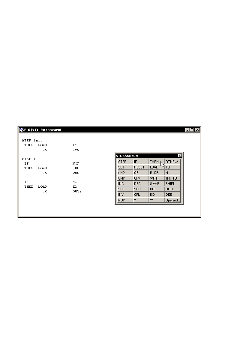
Creating a program 1. Select [Program] [New...]
2. Select the programming language (e.g. Statement List) in
the window New program".
3. Confirm the next window without modifications
(Type program, Number 0, Version1).
4. Create a program:
Fig.1/9: Program window of the FST
1−18
Festo P.BE−CPX−FEC−EN en 0404NH
Page 36
1. System summary
5. When you first use operands in your program, they will be
automatically interrogated after being entered in the
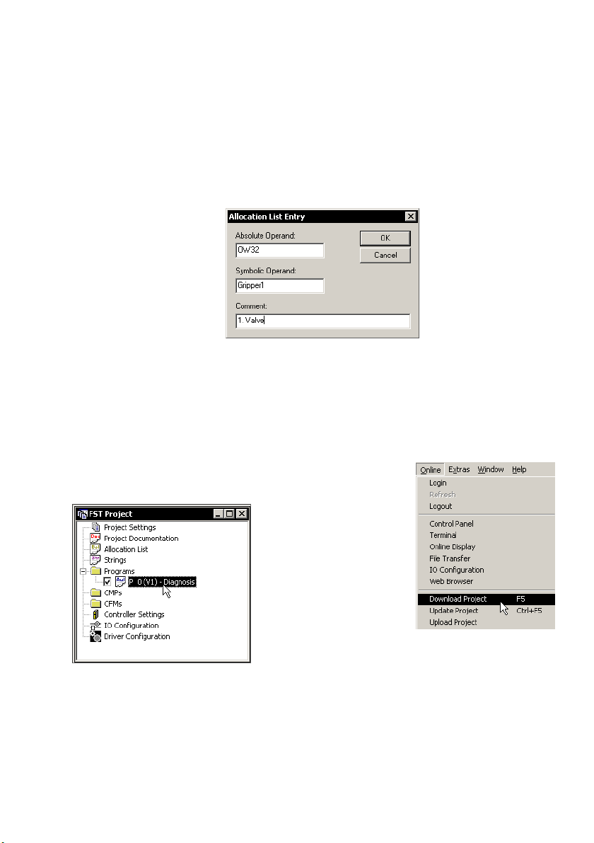
allocation list:
Fig.1/10: Interrogation for an entry in the allocation list
during programming
6. The new program is marked for loading automatically in
the project window. Load the project into the CPX−FEC
with [Online] [Download Project]:
Fig.1/11: A marked program is loaded into the FEC with the project
Festo P.BE−CPX−FEC−E N en 0404NH
1−19
Page 37
1. System summary
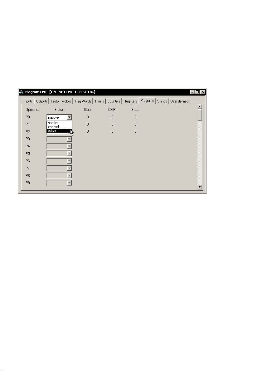
Start program 7. Set the rotary switch of the CPX−FEC to 1...F or start the
program in the Online TCPIP" display:
Fig.1/12: Program start with the Online TCPIP" display
1−20
Festo P.BE−CPX−FEC−EN en 0404NH
Page 38

Installation
Chapter 2
2−1Festo P.BE−CPX−FEC−E N en 0404NH
Page 39

2. Installation
Contents
2. Installation 2−1 . . . . . . . . . . . . . . . . . . . . . . . . . . . . . . . . . . . . . . . . . . . . . . . . . . .
2.1 General notes on installation 2−4 . . . . . . . . . . . . . . . . . . . . . . . . . . . . . . . . . . . . . .
2.2 Setting the switches of
2.2.1 Rotary switch 2−8 . . . . . . . . . . .
2.2.2 DIL switches 2−9 . . . . . . . . . . . . . . . .
2.3 Ethernet interface 2−11 . . . . . . . . . . . . . . . . . . . . .
2.3.1 Ethernet cable 2−11 . . . . . . . . . . . . . . . . . . . . . .
2.4 Programming interface (RS232) 2−13 . . . . . . . . . . . . . . . . . . . . . . . . . . . .
2.4.1 Pin assignment 2−13 . . . . . . . . . . . . . . . . . . . . . . . . . . . . . . . . . . . . . . . . .
2.4.2 Connecting a programming PC 2−14 . . . . . . . . . . . . . . . . . . . . . . . . . . . . .
2.4.3 Connecting the Front End Display FED−50/90 2−17 . . . . . . . . . . . .
2.5 Service interface for handheld 2−18 . . . . . . . . . . . . . . . . . . . . . . . . . . . . . . . . . . . .
2.6 Compliance with protection class IP65/IP67 2−19
the FEC 2−8 . . . . . . . . . . . . . . . . . . . . . . . . . . . . . . . . . . . .
. . . . . . . . . . . . . . . . . . . . . . . . . . . . . . . .
. . . . . . . . . . . . . . . . . . . . . . . . . . . .
. . . . . . . . . . . . . . . . . . . . . . . . . .
. . . . . . . . . . . . . . . . . . . .
. . . . . . .
. . . . .
. . . . . . . . . . . . . . . . . . . . . . . . .
2−2
Festo P.BE−CPX−FEC−EN en 0404NH
Page 40

2. Installation
Contents of this chapter In this chapter you will find information on:
Setting the switches of the CPX−FEC
Connecting devices, to field bus and Ethernet
The pin assignment of the interfaces
Compliance with protection class IP65/IP67
Further information Further information can be found here:
Fitting, installation and the power supply of the complete
CPX terminal: CPX
system manual (P.BE−CPX−SYS−..)
Installing I/O modules and pneumatic interface: Manual
for the CPX pneumatic interface and CPX I/O modules
(P.BE−CPX−EA−..)
Handheld: Manual for the universal handheld CPX−MMI−1
(P.BE CPX−MMI−1−..)
Festo P.BE−CPX−FEC−E N en 0404NH
Instructions on installing the pneumatic components can be
found in the relevant pneumatics manual (see Tab.0/2).
2−3
Page 41
2. Installation
2.1 General notes on installation
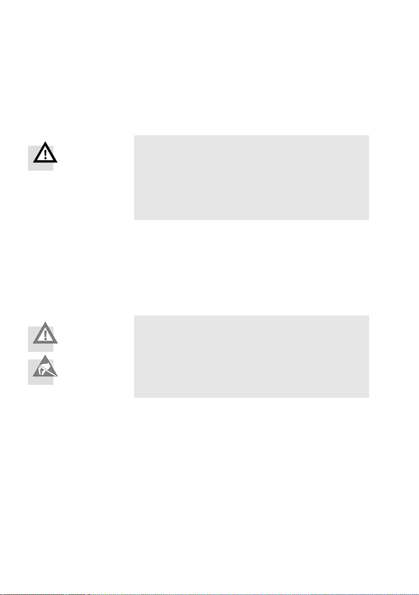
Warning
Before carrying out installation and/or maintenance work,
switch off the following:
the compressed air supply
the operating voltage supply for the electronics/sensors
the load voltage supply for the outputs/valves.
You will thereby avoid:
uncontrolled movements of loose tubing
uncontrolled movements of the connected actuators
undefined switching states of the electronics.
2−4
Caution
The CPX−FEC contains electrostatically sensitive compo
nents.
· Do not touch the electrical contacts of the components.
· Observe the regulations for handling electrostatically
sensitive components.
In this way you will avoid damage to the electronics.
Information on fitting the CPX terminal can be found in the
CPX system manual (P.BE−CPX−SYS−..).
Festo P.BE−CPX−FEC−EN en 0404NH
Page 42
2. Installation
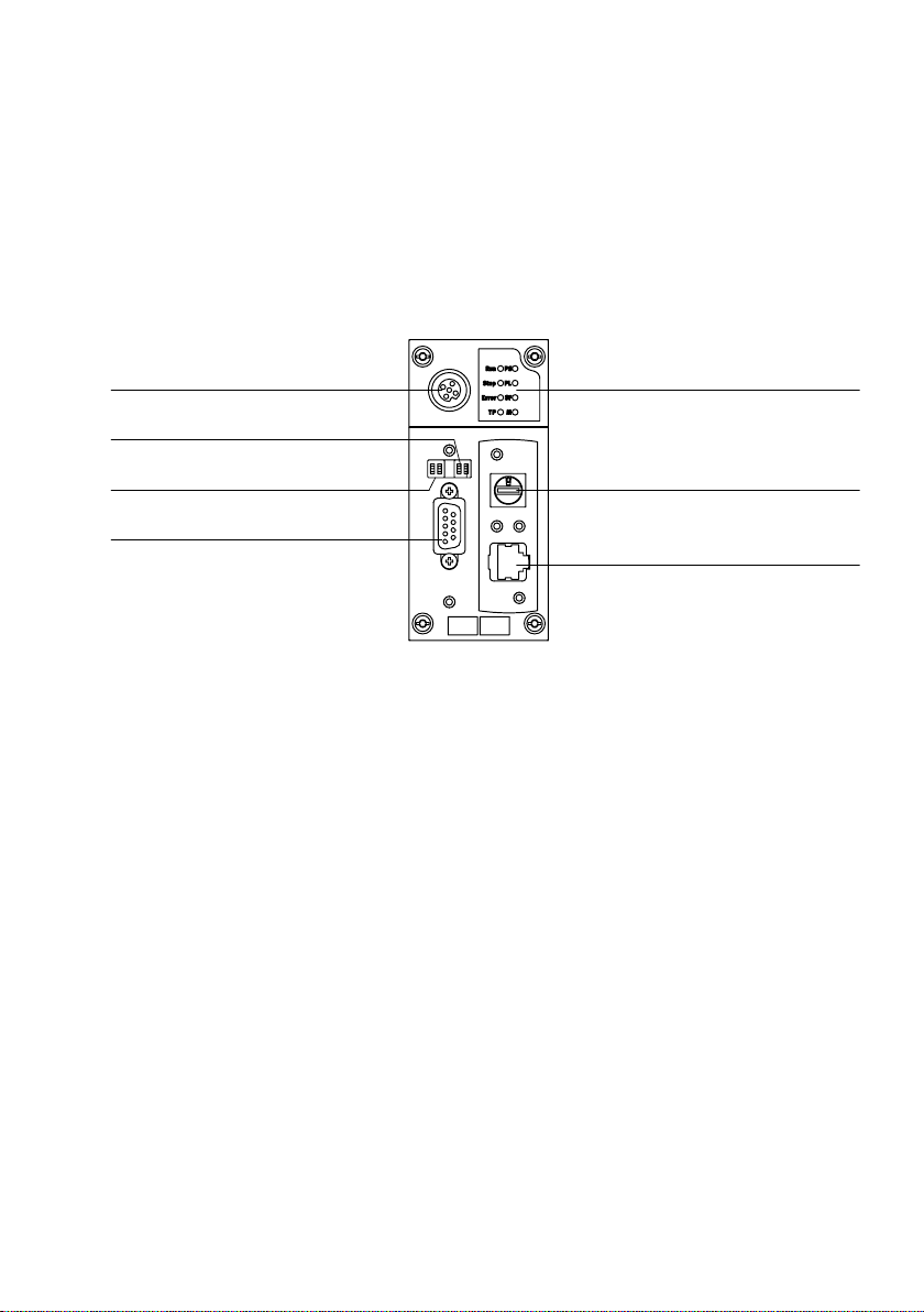
Electrical connecting and display elements
The following connecting and display elements can be found
on the CPX−FEC:
7
6
5
4
1 FEC status and CPX−specific LEDs
5 2−element DIL switch 1
(select operating mode)
2 16−element rotary switch
(RUN/STOP, Program selection)
3 Ethernet interface
(10/100BaseT, RJ45)
6 2−element DIL switch 2 (reserved)
7 Service interface for handheld (V24)
4 Programming interface
(RS232, 9−pin sub−D socket)
Fig.2/1: Connecting and display elements on the CPX field bus node
1
2
3
Festo P.BE−CPX−FEC−EN en 0404NH
2−5
Page 43
2. Installation
Dismantling and fitting
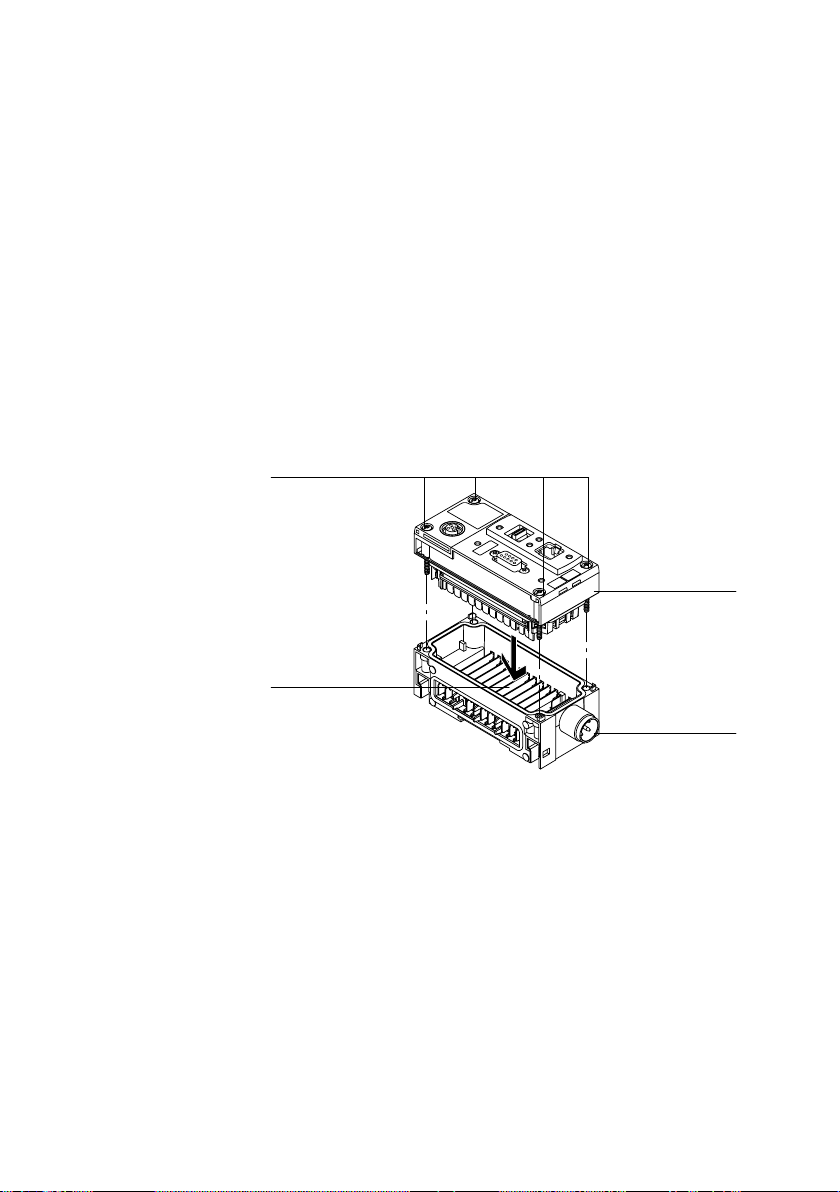
The FEC is fitted in a manifold sub−base of the CPX terminal
(see Fig.2/2).
Dismantling Dismantle the FEC as follows:
1. Loosen the four screws of the FEC with a Torx screwdriver
size T10.
2. Pull the FEC carefully and without tilting away from the
contact rails of the manifold sub−base.
1 CPX−FEC
4
2 Manifold sub−base
3 Contact rails
4 Torx T10 screws
3
Fig.2/2: Dismantling/fitting the CPX−FEC
1
2
2−6
Festo P.BE−CPX−FEC−EN en 0404NH
Page 44

2. Installation
Fitting Fit the FEC as follows:
1. Place the FEC in the manifold sub−base. Make sure that
the grooves with the terminals for electrical contact on
the bottom of the field bus node lie directly above the
contact rails. Press the FEC carefully and without tilting as
far as possible into the manifold sub−base.
2. Insert the
screws so that the self−boring threads can be
used. Tighten the screws at first only by hand.
Tighten the screws with a Torx screwdriver size T10 with
0.9 ... 1.1 Nm.
Festo P.BE−CPX−FEC−EN en 0404NH
2−7
Page 45
2. Installation
2.2 Setting the switches of the FEC
2.2.1 Rotary switch
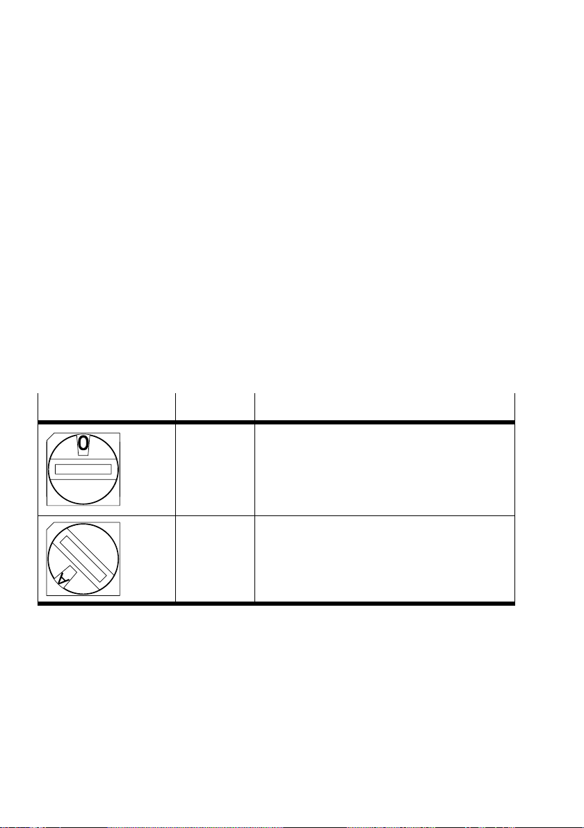
The 16−element rotary switch (0, 1, ..., F) serves as a RUN/
STOP switch for the PLC.
Leave the rotary switch at position 0" (STOP) during
installation.
Modifications to the position of the rotary switch are trans
mitted to the controller with a delay of 500 ms. In this way,
you can switch between
intermediate positions having any effect.
two switch positions without the
Rotary switch
Setting Meaning
0 STOP
PLC program has stopped.
Programs stop when the rotary switch is modified
from 1 ... F to 0.
1 ... F RUN
User program started.
Programs start when the rotary switch is modified
from 0 to 1 ... F.
The switch position can be interrogated in the user
program and used for programming purposes.
Tab.2/1: Possible settings of the rotary switch for the PLC
2−8
Festo P.BE−CPX−FEC−EN en 0404NH
Page 46
2. Installation
2.2.2 DIL switches
Please note
Check that the setting of the DIL switch is correct before
commissioning the CPX−FEC.
A change in the operating mode is not recognized until
after Power OFF/ON.
The DIL switches must be accessible in order that the
CPX−FEC can be set:
· Remove an IP65/IP67 plug, if fitted, from the program
ming interface.
Setting the operating mode with DIL switch 1
You can set the operating mode of the FEC with switch
element 1 of DIL switch 1.
Festo P.BE−CPX−FEC−EN en 0404NH
2−9
Page 47
2. Installation
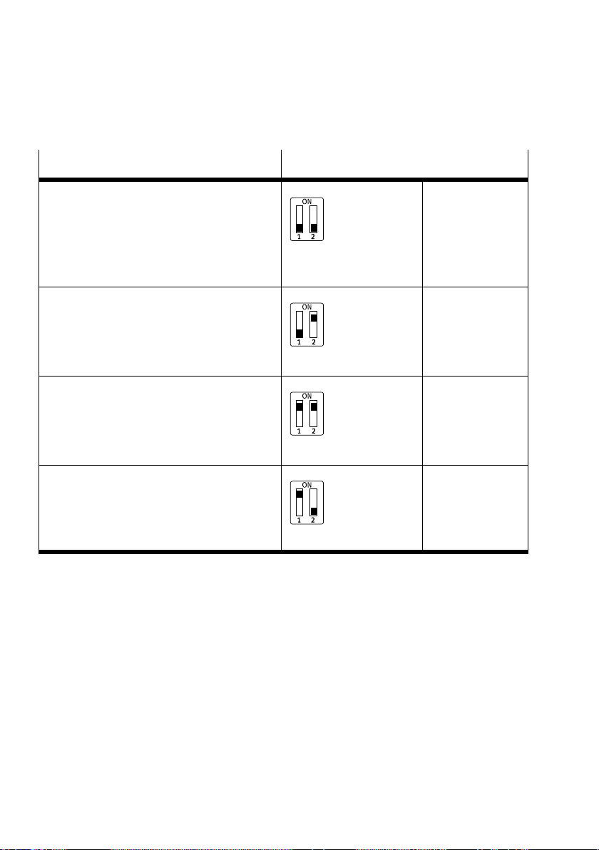
Operating mode Setting DIL switch 1
Stand Alone / Remote Controller
Controlling the CPX terminal via the CPX−FEC:
Stand Alone
or
Ethernet Remote Controller
or
Field bus Remote Controller
Remote I/O
Controlling the CPX terminal via Modbus/TCP
with a higher−order controller.
Reserved DIL 1.1: ON
Reserved DIL 1.1: ON
DIL 1.1: OFF
DIL 1.2: OFF
DIL 1.1: OFF
DIL 1.2: ON
DIL 1.2: ON
DIL 1.2: OFF
Tab.2/2: Setting the operating mode
2−10
Reserved DIL switch 2
Leave the switch elements of DIL switch 2 set to OFF.
Festo P.BE−CPX−FEC−EN en 0404NH
Page 48
2. Installation
2.3 Ethernet interface
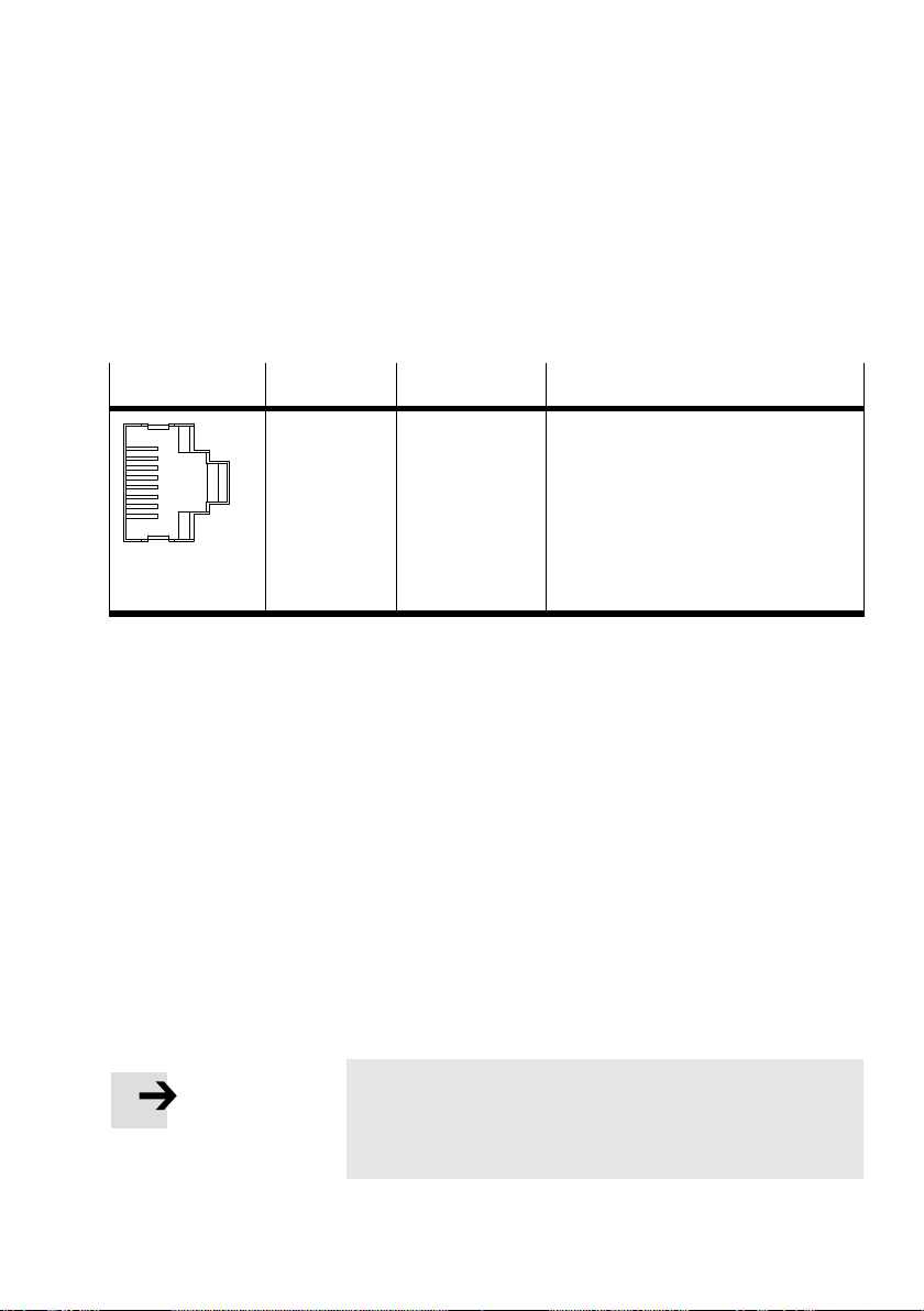
There is a RJ45 socket on the CPX−FEC for connection to the
Ethernet.
RJ45 socket
8
7
6
5
4
3
2
1
Pin Signal Explanation
1
2
3
4
5
6
7
8
Metal covering
TD+
TD
RD+
n.c.
n.c.
RD
n.c.
n.c.
Screening/shield
Send data +
Send data
Receive data +
not connected
not connected
Receive data
not connected
not connected
Screening/shield
Tab.2/3: Pin assignment of the Ethernet interface
If the Ethernet interface is not used, seal it with a cover of
type AK−RJ45, part no. 534496. You will then comply with
protection class IP65/IP67.
2.3.1 Ethernet cable
Use as connecting cable:
Cable specification Screened flexible Ethernet round cable of category 5;
max. outer diameter: 5.4 mm
core diameter: 0.89 ... 1.0 mm AWG24−26
ready made: Crimping pliers on RJ45
Festo P.BE−CPX−FEC−EN en 0404NH
Please note
If the CPX terminal is fitted onto a moving par t of a
machine, the Ethernet cable on the moving part must be
provided with strain relief.
2−11
Page 49
2. Installation
Network connection In order to connect your CPX−FEC to a network or PC you will
require:
a Patch cable for connecting via hub or switch
a crossover cable for direct connection of the PC and the
CPX−FEC.
Please note
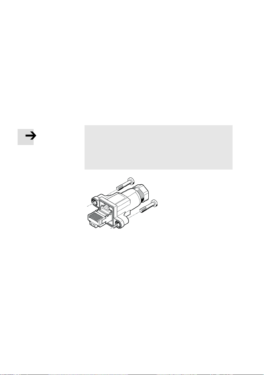
Use the RJ45 plug from Festo in order to comply with
protection class IP65/IP67.
Type F BS−RJ45−8−GS, part no. 534494
Observe the fitting instructions for the plug.
2−12
Fig.2/3: RJ45 plug complying with protection class
IP65/IP67
Festo P.BE−CPX−FEC−EN en 0404NH
Page 50
2. Installation
2.4 Programming interface (RS232)
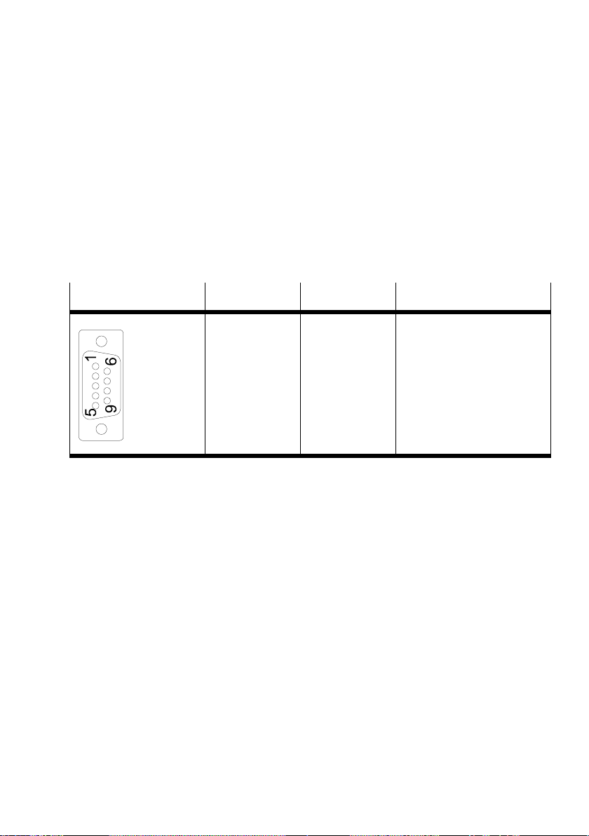
There is 9−pin sub−D socket on the CPX−FEC for connecting a
programmer, a PC or F EDs.
2.4.1 Pin assignment
Socket on the CPX−FEC Pin Signal Explanation
1
2
3
4
5
6
7
8
9
Screening/shield
n.c.
RxD
TxD
n.c.
GND
n.c.
n.c.
n.c.
n.c.
Screening/shield
Tab.2/4: Pin assignment of the programming interface
If the programming interface is not used, seal it with the
transparent cover.
type AK−SUB−9/15−B
part no. 533334
max. tightening torque 0.4 Nm
not connected
Receive data
Send data
not connected
Data reference potential
not connected
not connected
not connected
not connected
Connection to functional earth
Festo P.BE−CPX−FEC−EN en 0404NH
2−13
Page 51
2. Installation
2.4.2 Connecting a programming PC
Use the programming cable from Festo in order to connect
your PC to the CPX−FEC:
type KDI−PPA−3−BU9
part no. 151915
Please note
Use the above programming cable only for the program
ming environment. It has only one screening connection
on one side and complies only with protection class IP20.
Use an RS232 cable with screening/shield connection on
both sides for communication or control.
2−14
The next section describes how to produce an RS232
which complies with protection class IP65/IP67.
Please note
Lay the cable
not twisted
without bends
at a sufficient distance from current−carrying cables.
You will then avoid transmission faults between the PC
and the FEC.
Festo P.BE−CPX−FEC−EN en 0404NH
cable
Page 52
2. Installation
RS232 cable with protection class IP65/IP67
For an RS232 cable which complies with protection class
IP65/IP67 you will require:
a programming plug from Festo (Fig.2/4)
typeFBS−SUB−9−GS−1X9POL−B
a 3−core screened cable.
Please note
Only the programming plug from Festo guarantees com
pliance with protection class IP65/IP67. If you also need
to comply with protection class IP65/IP67 in the program
ming environment:
· Relpace the two flat screws by threaded sleeves (type
UNC 4−40/M3x6, part no. 533000) before connecting
sub−D plugs of other manufacturers.
Festo P.BE−CPX−FEC−EN en 0404NH
1. Fit a programming cable in accordance with the fitting
instructions for the plug.
2. When fitting the plug onto the CPX−FEC tighten the fasten
ing screws at first by hand and then with 0.4
Nm.
Please note
Observe the maximum permitted length of the cable as a
factor of the baud rate in accordance with RS232 specifica
tions.
2−15
Page 53
2. Installation
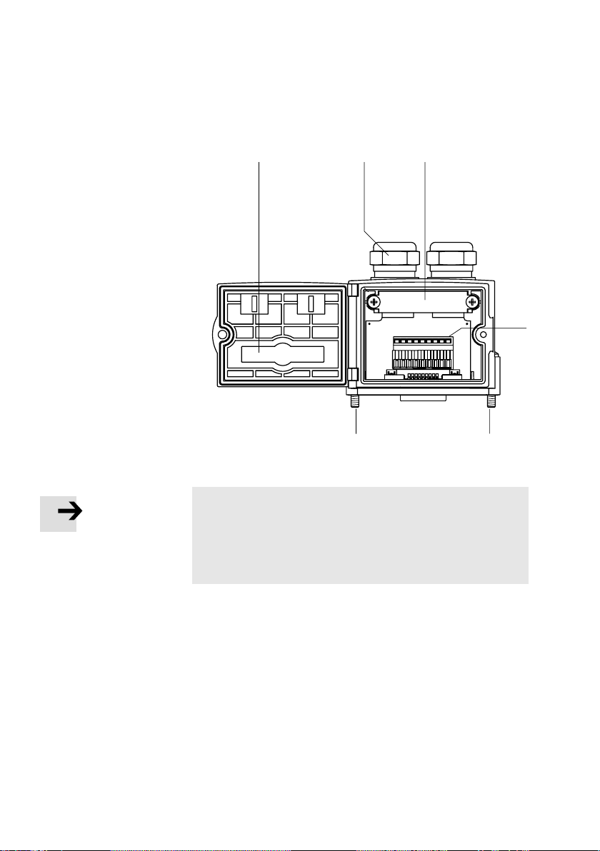
1 Hinged cover with
viewing window
213
2 Blanking plug if
connection is not
used
3 Clamp strap for
screening
connection
4 Terminal strip for
the cable
9
7
8
(pinassignment
see Tab.2/4)
5 Fastening screws
Fig.2/4: Programming plug from Festo, type FBS−SUB−9−GS−1X9POL−B
Please note
· Use protective caps or blanking plugs to seal unused
connections.
In this way you will comply with protection class
IP65/IP67.
3
12
456
55
4
2−16
Festo P.BE−CPX−FEC−EN en 0404NH
Page 54
2. Installation
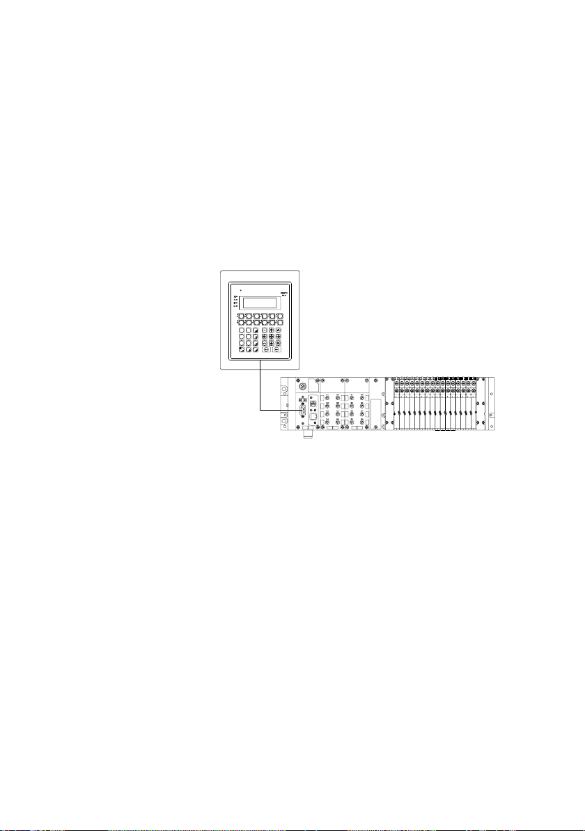
2.4.3 Connecting the Front End Display FED−50/90
You can connect an FED−50 or an FED−90 to the programming
interface of the CPX−FEC. The FED is an easy−to−use display
for operating and observing automation tasks at the field
level. FED operating devices are intended for fitting in the
front of a metallic housing.
Festo P.BE−CPX−FEC−EN en 0404NH
Fig.2/5: CPX terminal with FED−90
· Connect the FED to the CPX−FEC with connecting cable
type FEC−KBG7 or FEC−KBG8 (part no. 539642 resp.
539643).
2−17
Page 55
2. Installation
2.5 Service interface for handheld
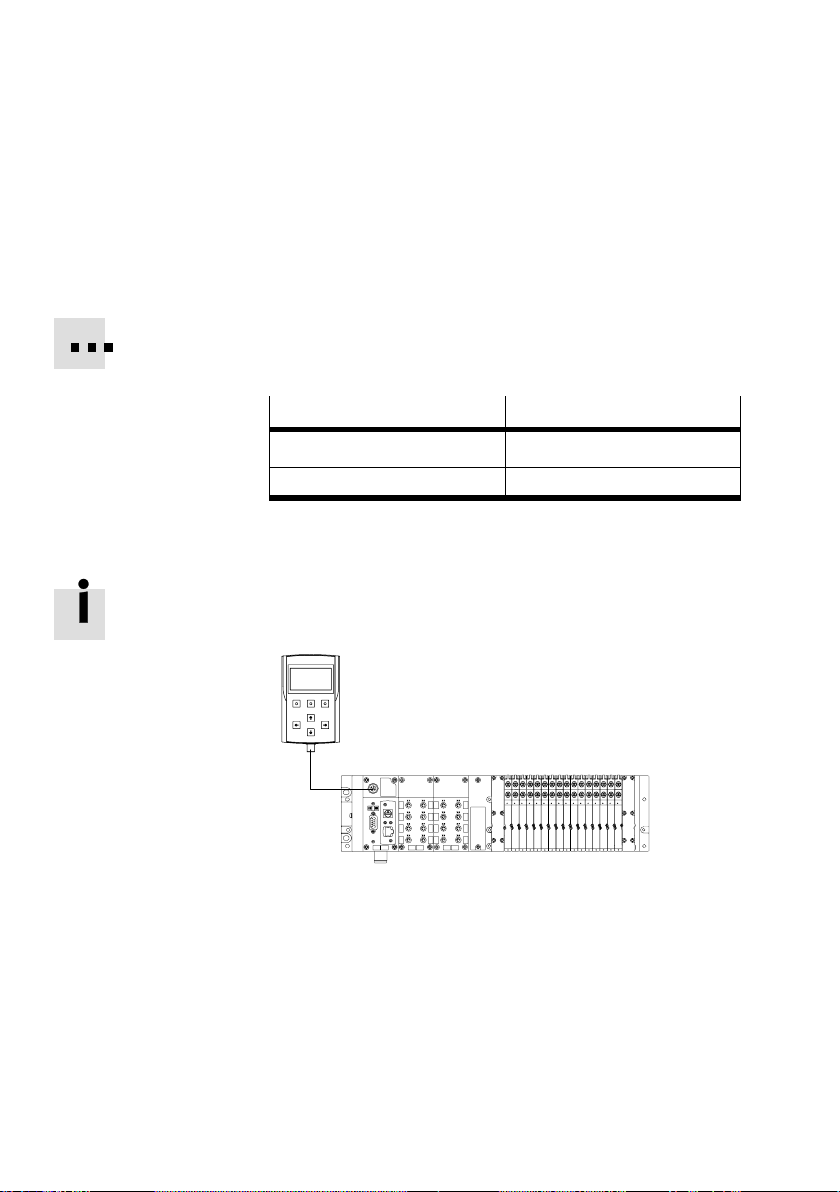
The 5−pin M12 socket serves for connecting a handheld for
fast preliminary commissioning, diagnosis or parametrizing.
Use only the following original cables for connecting the
handheld to the service interface:
Type
KV−M12−M12−3,5 3.5
KV−M12−M12−1,5 1.5
Cable length in [m]
Tab.2/5: Connecting cable for handheld
Information on the handheld can be found in the manual
Universal handheld type CPX−MMI−1".
Fig.2/6: CPX terminal with handheld
2−18
Festo P.BE−CPX−FEC−EN en 0404NH
Page 56
2. Installation
2.6 Compliance with protection class IP65/IP67
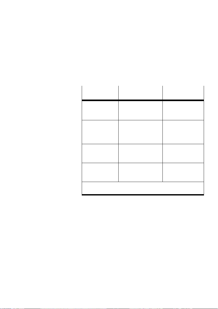
In order to comply with protection class IP65/IP67, seal un
used sockets and the switch with the appropriate covers.
Connection/
switch
Ethernet, RJ45 Plug
Programming
interface, sub−D
and DIL switch
Service interface,
M12
Rotary switch Cover
1)
If connection is not used
2)
Included in delivery
Connection
IP65/IP67
type FBS−RJ45−8−GS
part no. 534494
Plug from Festo
type FBS−SUB−9−GS−
1X9POL−B
part no. 534497
Connecting cable and
plug for the handheld
1)
Cover
IP65/IP67
2)
Cover
type AK−RJ45
part no. 534496
Transparent cover
type AK−SUB−9/15−B
part no. 533334
Protective cap
type ISK−M12
part no. 352059
2)
type AK−RJ45
part no. 534496
Tab.2/6: Connections and covers for protection class
IP65/IP67
2)
2)
Festo P.BE−CPX−FEC−EN en 0404NH
2−19
Page 57

2. Installation
2−20
Festo P.BE−CPX−FEC−EN en 0404NH
Page 58

General operation (Stand Alone)
Chapter 3
3−1Festo P.BE−CPX−FEC−E N en 0404NH
Page 59

3. General operation (Stand Alone)
Contents
3. General operation (Stand Alone) 3−1 . . . . . . . . . . . . . . . . . . . . . . . . . . . . . . . . . .
3.1 Configuration 3−4 . . . . .
3.1.1 Create connection to CPX−FEC 3−4 . .
3.1.2 Creating a project 3−5 . . . . . . . . . . . . . . . . . . . .
3.1.3 Fast configuration by loading the actual configuration 3−8 . . . . . . . . . .
3.1.4 Manual configuration with the Hardware Configurator 3−10 . . . . . . . . .
3.2 Addressing 3−19 . . . . . . . . . . . . . . . . . . . . . . . . . . . . . . . . . . . . . . . . . . . . . . . .
3.2.1 Default addressing 3−19 . . . . . . . . . . . . . . . . . . . . . . . . . . . . . . . . . . . . . .
3.2.2 Individual addressing 3−20 . . . . .
3.2.3 Addressing example 3−21 . . . . . . . . . . . . . . . . .
3.3 Parametrizing 3−27 . . . . . . . . . . . . . . . . . . . . . . . . . . . . . .
3.3.1 Parametrizing with the handheld 3−29 . . . . . . . . . . . . . . . . . . . . . . . . . .
3.3.2 Parametrizing with the Hardware Configurator of the FST 3−29 . . . . . . .
3.3.3 Parametrizing from a user program 3−34 . . . . . . . . . . . . . . . . . . . . . . . . .
3.3.4 Forcing 3−35 . . . .
3.3.5 Application example for the parametrizing 3−38 .
3.4 Programming the CPX−FEC 3−39 . . . . . . . . . . . . . . . . . . . . . . . . . . . . . .
3.4.1 Overview of operands 3−40 . . . . . . . . . . . . . . . . . . . . . . . . . . . . . . . . . . . .
3.4.2 Overview
3.4.3 Overview of function modules for the CPX terminal 3−45 . . . . . .
3.4.4 User programs 3−46 . . . . . . . . . . . . . . . . . . . . . . . . . . . . . . . . . . . . . . . . . .
3.4.5 Program example (STL) 3−50 . . . . . . . . . . . . . . . . . . . . . . . . . . . . . . . . . . .
3.5 Diagnosis 3−52 . . . . . . . . . . . .
3.5.1 Diagnosis with the controller LEDs RUN, STOP and ERROR 3−53
3.5.2 Diagnosis with the Hardware Configurator 3−55 . . . . . . . . . . . . . . . . . . .
3.5.3 Diagnosis in the user program 3−59 . . . . . . . . . . . . . . . .
3.6 Access and control via CI commands 3−61 . . . . . . . . . . . . . . . . . . . . . . . . . . . . . . .
. . . . . . . . . . . . . . . . . . . . . . . . . . . . . . . . . . . . . . . . . . . . .
. . . . . . . . . . . . . . . . . . . . . . . . . . .
. . . . . . . . . . . . . . . . . . .
. . . .
. . . . . . . . . . . . . . . . . . . . . . . . . . . . . . .
. . . . . . . . . . . . . . . . . . . .
. . . . . . . . . . . . . . . . . . . .
. . . . . . . . . . . . . . . . . . . . . . . . . . . . . . . . . . . . . . . . . . . .
. . . . . . . . . . . . . . . . . .
. . . . . . . . . .
of operations 3−41 . . . . . . . . . . . . . . . . . . . . . . . . . . . . . . . . . . .
. . . . . .
. . . . . . . . . . . . . . . . . . . . . . . . . . . . . . . . . . . . . . . . .
. . . . . .
. . . . . . . . . . . . .
.
.
3−2
Festo P.BE−CPX−FEC−EN en 0404NH
Page 60

3. General operation (Stand Alone)
Contents of this chapter This chapter is the basis for operating the CPX−FEC in the
operating modes:
Stand Alone
Remote Controller (see chapter 5)
Here you will find a description of general commissioning,
parametrizing, programming and diagnosis of the CPX−FEC.
If you operate the CPX−FEC without communication connec
tion to other slaves, this corresponds to
the operating mode
Stand Alone. In this operating mode the FEC controls the
CPXterminal independently.
Preparing for
commissioning
Installation in accordance with chapter 2
The correct operating mode is set with DIL switch 1
(seesection 2.2.2)
FST 4.1 or higher is installed on the programming PC
Overview
of the following commissioning steps
1. Configuring the CPX terminal with FST
2. If desired: Parametrize
3. Create program
4. Load project into CPX−FEC
5. Start and test program
Various diagnostic possibilities are available during commis
sioning and during operation.
Festo P.BE−CPX−FEC−E N en 0404NH
3−3
Page 61
3. General operation (Stand Alone)
3.1 Configuration
Use Festo Software Tools (FST 4.1 or higher) with the Hard
ware Configurator in order to configure your CPX terminal
with CPX−FEC. In the following sections you will find the most
important commissioning steps with FST 4.1.
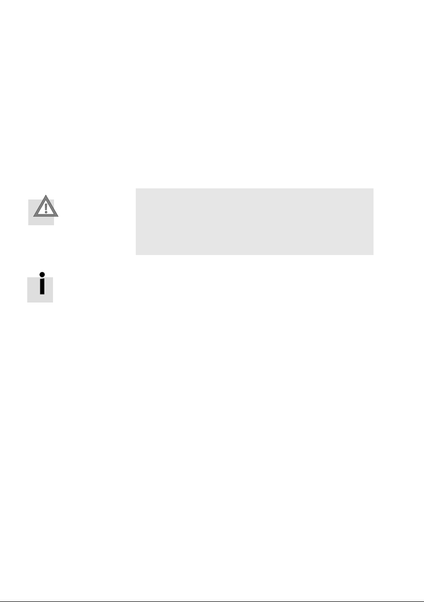
Caution
If you have connected a CPX terminal to your PC for con
figuration: Test projects and programs at first without ac
tive actuators or without compressed air.
You will then avoid damage in the test phase.
A tutorial on configuration with FST can be found in sec
tion1.5. Detailed information on operating the FST can be
found in the FST manual (type P.BE−FST−..).
Follow the instructions in order to carry out a first project
with the CPX−FEC.
3.1.1 Create connection to CPX−FEC
You will require a connection between your PC and the
CPX−FEC if you wish to load projects into the FEC or use the
online functions.
You can use all online functions via the programming
interface or the Ethernet interface. Access to the
Web−Browser is only possible via the Ethernet interface.
Create connection to
theCPX−FEC
3−4
1. Set the rotary switch of the CPX−FEC to 0".
2. Connect your PC and the CPX−FEC either
via the programming interface with an RS232 cable
(see section 2.4) or
Festo P.BE−CPX−FEC−EN en 0404NH
Page 62

3. General operation (Stand Alone)
via the Ethernet interface with a patch cable (connec
3. Access the window FST Preferences" in FST 4.1 with
[Extras] [Preferences...]. Select your type of connection in
the register Communication".
Programming interface Use RS232"
Ethernet interface Use TCP/IP"
4. Confirm with OK.
tion via hub/switch) or with a crossover cable (direct
connection) (see section 2.3).
Set the local COM interface of your PC
and the
baudrate.
Set the IP address of your CPX−FEC or click on
Search" in order to display a list of the online avail
able controllers. Select your controller with a double
click.
Information on the IP addressing can be found in
section 4.3.2.
3.1.2 Creating a project
Festo P.BE−CPX−FEC−EN en 0404NH
Create a new project in FST as follows:
1. [Project] [New...]
2. Assign a project name.
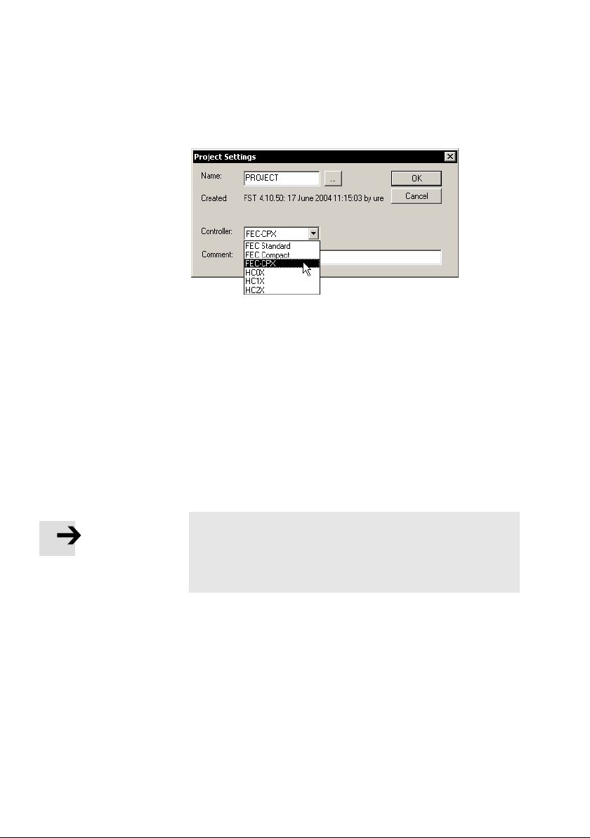
3. Select the CPX−FEC as controller in the window
Project Settings".
3−5
Page 63
3. General operation (Stand Alone)
Fig.3/1: Select the CPX−FEC when creating a new project.
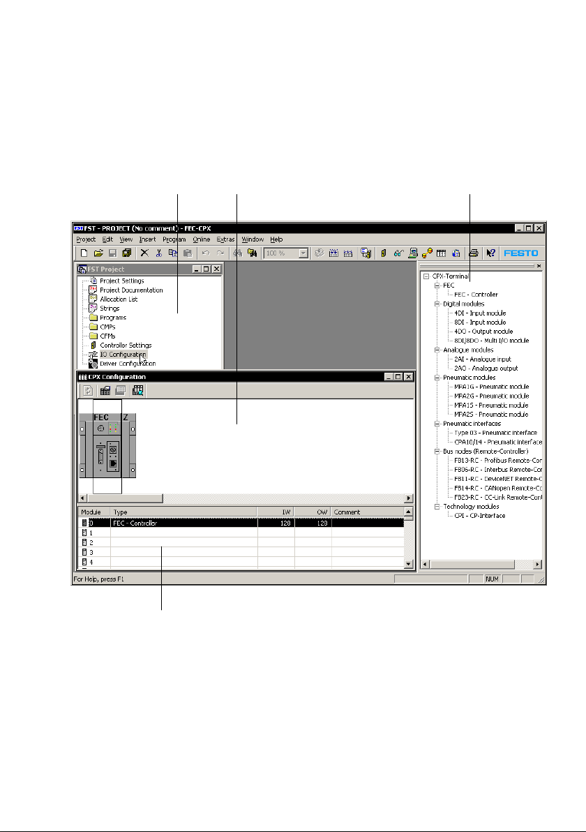
4. Start the Hardware Configurator with a double click on
IO Configuration" in the project window of the FST
(seeFig.3/2).
If the project window is not displayed: Select [View]
[Project Window].
5. The CPX configuration window and the Hardware
Catalogue will be displayed.
If the Hardware Catalogue is
[Catalog].
not displayed: Select [View]
3−6
Please note
Note the register Download" in the Controller settings".
· Select Download source files" if you wish to download
the project later from the CPX−FEC (e.g. on another PC).
Festo P.BE−CPX−FEC−EN en 0404NH
Page 64
3. General operation (Stand Alone)
When a new project is created with the CPX−FEC, a CPX−FEC
will automatically be numbered module 0:
12
4
3
Project window
1
2 Hardware Configurator
Fig.3/2: FST 4.1 with Hardware Configurator after creation of a new project
Festo P.BE−CPX−FEC−EN en 0404NH
3 Hardware Catalogue
4 Configuration table
3−7
Page 65

3. General operation (Stand Alone)
3.1.3 Fast configuration by loading the actual configuration
If you have already connected a completely equipped and
installed CPX terminal to your PC, there are two ways of
loading the configuration:
Actual−nominal comparison in the editor mode
Change to the online mode
Actual−nominalcomparison
Actual−nominal
comparison
1. Click on [Actual−Nominal−Comparison] in the context
menu.
The actual configuration of
the connected CPX terminal
will be loaded and displayed together with the nominal
configuration.
2. You can decide which modules in the actual configur
ation you wish to transfer by selecting them with the
check box in the first column.
3. In the lower range select under Use actual settings
for..." whether current parameter settings, the
address
assignment (mapping) or the Idle mode/Fail safe set
tings are to be transferred.
4. Click on Apply" in order to transfer the selection to the
current project.
The Hardware Configurator remains in the editor mode.
3−8
Festo P.BE−CPX−FEC−EN en 0404NH
Page 66
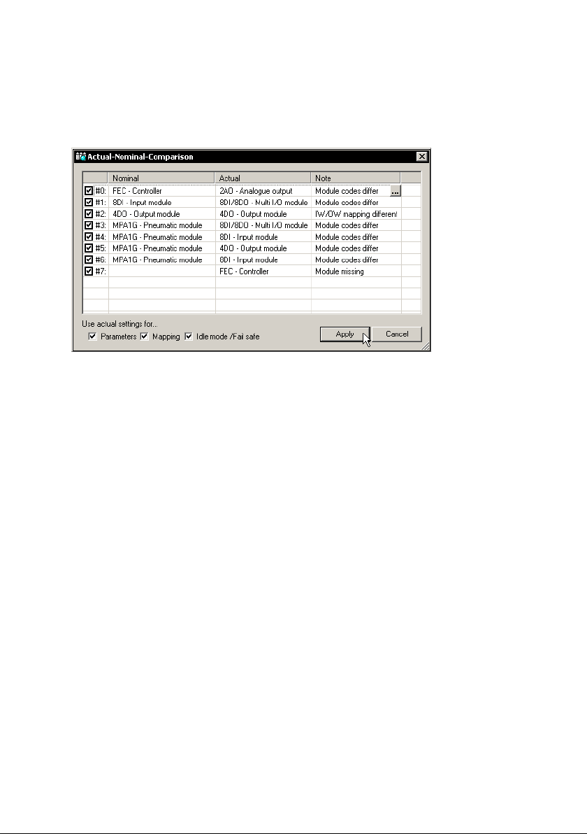
3. General operation (Stand Alone)
Fig.3/3: Load the configuration of a connected CPX terminal with the function
Actual−Nominal−Comparison" in the editor mode.
If the actual−nominal comparison does not lead to a result:
1. Check the communication settings of the FST under
[Extras] [Preferences...] register Communication".
2. Check the communication connection between the
CPX−FEC and your PC.
Change to the
online mode
Online mode The second possibility of loading the current configuration
is to change to the online mode.
1. Select the entry [Online] in the menu [Online] or click on
Online" in the context menu:
The configuration of the CPX terminal will be loaded and
transferred to the Hardware Configurator.
2. Select [Save]
in the context menu, in order to save the
loaded configuration in your project.
The Hardware Configurator is now connected online with
the CPX terminal.
Festo P.BE−CPX−FEC−EN en 0404NH
3−9
Page 67

3. General operation (Stand Alone)
3.1.4 Manual configuration with the Hardware Configurator
Use this type of configuration if you wish to configure first
only on the PC when there is no connection to a CPX terminal.
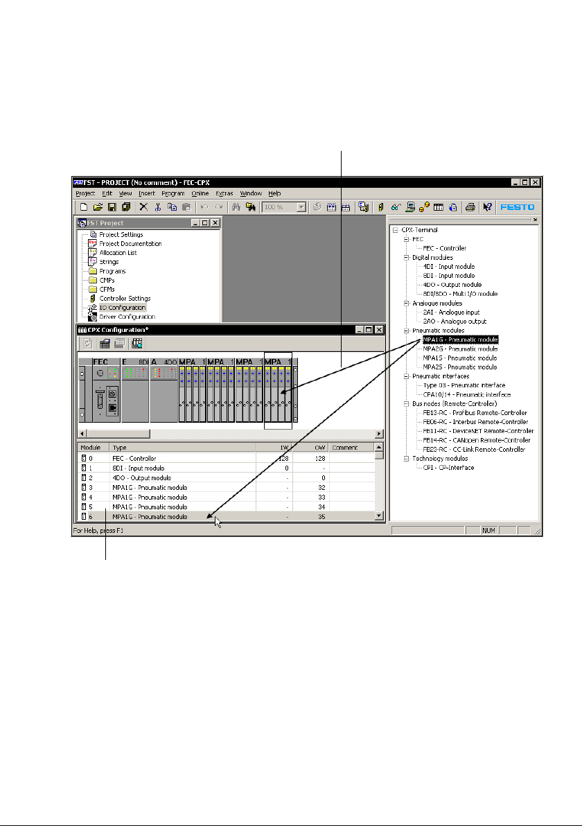
Configuration is carried out with drag & drop:
1. Pull the modules out of the Hardware Catalogue into the
Hardware Configurator. You can pull the modules onto the
graphic representation
the configuration table.
Configure the modules from left to right corresponding to
the physical sequence in your CPX terminal.
2. The addresses will be assigned automatically in accord
ance with the default addressing.
Modifying addresses: Click directly on the address in the
configuration table and modify the value.
Deleting modules · Mark the module to be deleted and press the Del"
button.
of the CPX terminal or directly into
3−10
Festo P.BE−CPX−FEC−EN en 0404NH
Page 68
3. General operation (Stand Alone)
1
2
1 Configuration with drag & drop 2 Configured modules in the
configuration table
Fig.3/4: Manual configuration of the CPX terminal in the Hardware Configurator
Festo P.BE−CPX−FEC−EN en 0404NH
3−11
Page 69

3. General operation (Stand Alone)
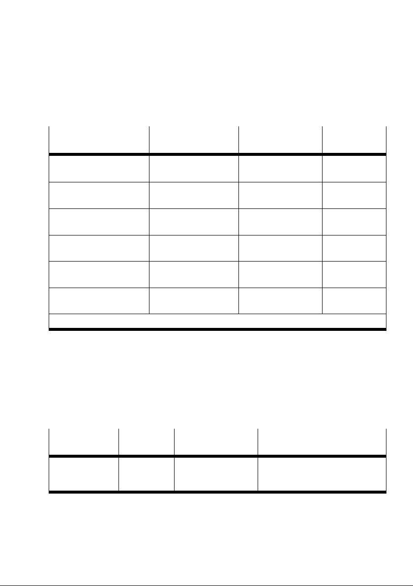
Below you will find information on the CPX modules.
Module CPX−FEC
You can configure the controller of your CPX terminal with
this module.
Module
Module
identifiers
FEC controller FEC 1 word I
1) Module identifiers on the handheld and in the Hardware Configurator of the FST 4.1
Assigned address
1)
range
1 word O
Remarks
The inputs form the position of
the rotary switch.
The outputs are not used.
Tab.3/1: Module CPX−FEC
3−12
Festo P.BE−CPX−FEC−EN en 0404NH
Page 70
3. General operation (Stand Alone)
Electric modules
Module
(order code)
Digital 4−input module
(F: CPX−4DI)
Digital 8−input module
(I: CPX−8DI)
Digital 4−output module
(O: CPX−4DO)
Digital multi I/O module
(Y: CPX−8DE−8DO)
Analogue 2−input module
(U: CPX−2AE−U/I)
Analogue 2−output module
(P: CPX−2AA−U/I)
1)
Module identifiers on the handheld and in the Hardware Configurator of the FST 4.1
Module identifiers 1)Assigned address
range
4DI 1 word I
8DI 1 word I
4DO 1 word O
8DI/8DO 1 word I
1 word O
2AI 2 words I
2AO 2 words O
Tab.3/2: Overview of electric CPX modules
Technology module CP interface
With the aid of this module you can connect CP components
to the CPX terminal.
Remarks
Module
Module
identifiers
CP interface CPI max. 8 words I
Assigned address
range
max. 8 words O
Tab.3/3: Technology module CP interface
Festo P.BE−CPX−FEC−EN en 0404NH
Remarks
The number of assigned addresses
depends on the string assignment
saved in the CP interface.
3−13
Page 71
3. General operation (Stand Alone)
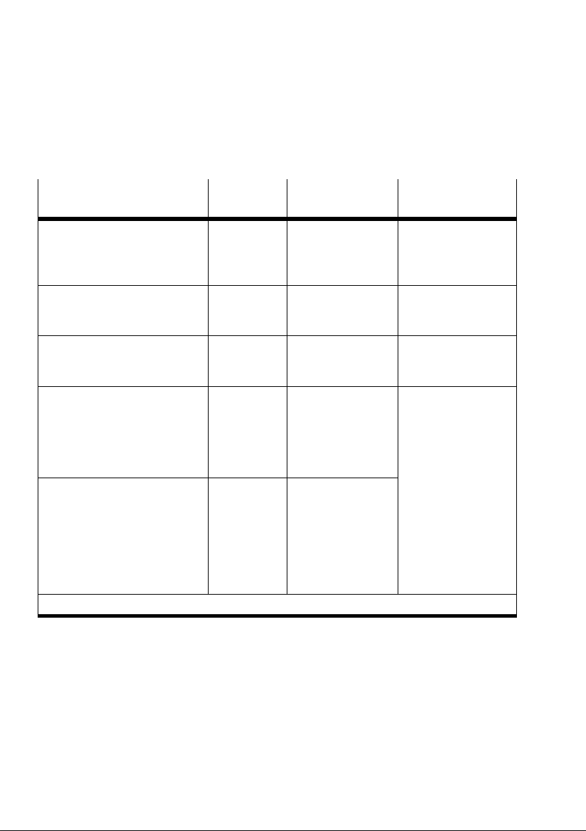
Pneumatic modules
Module
(order code)
Pneumatic interface for MPA
valves (type 32)
MPA pneumatic module (type 32)
without electrical isolation
(VI: CPX type 32: 1−..V..)
MPA pneumatic module (type 32)
with electrical isolation
(VI: CPX type 32−G: 1−..V..)
Pneumatic interface for CPA
valves (type 12)
(VI: CPX type 12: 1−..V..)
Pneumatic interface for
Midi/Maxi valves (type 03)
(VI: CPX type 03: 1−..V..)
1)
Module identifiers on the handheld and in the Hardware Configurator of the FST 4.1
Module
identifiers
This module is not
MPA1S
MPA2S
MPA1G
MPA2G
CPA10/14 1...8 valve coils:
Type 03 1...8 valve coils:
Assigned address
1)
range
1 word O
1 word O
1 word O
1...16 valve coils:
1 word O
1...22 valve coils:
2words O
1 word O
1...16 valve coils:
1 word O
1...24 valve coils:
2 words O
1...26 valve coils:
2 words O
Remarks
displayed in the
Hardware Configurator
(passive module).
The representation of
the CPA and Midi/Maxi
valves in the Hardware
Configurator is only
symbolic and can
differ from the actual
number of valves.
Tab.3/4: Overview of pneumatic interfaces and MPA pneumatic modules
3−14
Festo P.BE−CPX−FEC−EN en 0404NH
Page 72
3. General operation (Stand Alone)
Configure the valves according to the pneumatic type used.
The pneumatics must always be configured last.
Valves of type 32 (MPA pneumatic modules)
The individual MPA pneumatic modules each provide an elec
tric module with digital outputs for controlling the valves. A
word of outputs is always
module, irrespective of the number of valves fitted on the
pneumatic module (see Tab.3/4).
Further information on MPA pneumatic modules can be found
in the manual for the CPX I/O modules (P.BE−CPX−EA−..) and in
the relevant pneumatics manual.
assigned for each MPA pneumatic
Valves of type 12 (CPA) and
type 03 (Midi/Maxi)
With these valves only the pneumatic interface is configured.
The number of valve coils is set with a DIL switch (see manual
CPX I/O modules, P.BE−CPX−EA−..).
Configuration 1. Pull the relevant pneumatic interface onto the next line
in the configuration table.
2. Double click on the line. The window
Module..." will be
displayed.
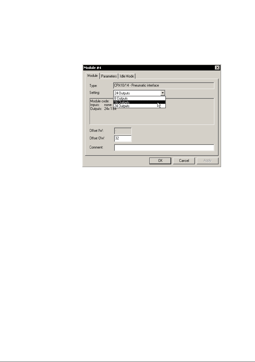
3. Switch to the register Module" and select the number of
valve coils as is set on the DIL switch in the pneumatic
interface:
Festo P.BE−CPX−FEC−EN en 0404NH
3−15
Page 73
3. General operation (Stand Alone)
Fig.3/5: Select the number of valve coils (configuration of
the valves of type 12 or type 03)
3−16
If you set a value which is greater than the actual number
of valve coils, the superfluous addresses will be reserved.
The representation of the CPA and Midi/Maxi valves in the
Hardware Configurator is only symbolic and
can differ
from the actual number of valves. The same number of
valves is displayed as the number of outputs which are
set, irrespective of whether there are single−solenoid
valves or double−solenoid valves in your CPX terminal.
Festo P.BE−CPX−FEC−EN en 0404NH
Page 74
3. General operation (Stand Alone)
Checking the configuration
A successful configuration is distinguished by:
module assignment without gaps
clear assignment of the master
pneumatic modules are situated at the right−hand end of
the CPX terminal
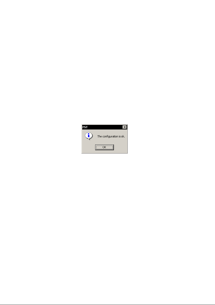
Check the configuration
· Click on Check Configuration" in the context menu:
Festo P.BE−CPX−FEC−EN en 0404NH
3−17
Page 75
3. General operation (Stand Alone)
Reset configuration
All parameter settings and the address assignment
(Mapping) can be reset to the factory settings.
Reset configuration The desired settings can be reset to the factory settings as
follows:
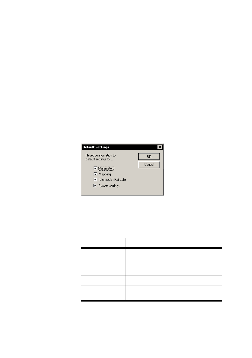
1. Select the command [Default Settings...] in the context
menu of the Hardware Configurator. The following dia
logue will then appear:
3−18
Fig.3/6: Announcement for configuration check (example)
2. Select the settings which are to be reset and confirm this
with OK.
Options
Parameter Module parameter without Idle mode and
Mapping Address assignment of the CPX terminal
Idle mode/Fail safe Idle mode and Fail safe parameters
System settings System parameters and diagnostic memory
Description
Failsafe
parameters
Tab.3/5: Options Reset configuration
Festo P.BE−CPX−FEC−EN en 0404NH
Page 76
3. General operation (Stand Alone)
3.2 Addressing
Basic rules for addressing
Modules occupy the address range in ascending order
from left to right according to their physical arrangement
in the CPX terminal (module−orientated).
Addressing is carried out word−orientated (16−bit I/O).
Different module types are assigned with different
addresses depending on the address range.
If a module occupies less than 1 word (16−bit I/O), the
remaining
If a module occupies more than 1 word I/O, the following
word in the address area will be used.
The address assignment can be modified module−orien
tated (see below).
bits of the word will not be used.
3.2.1 Default addressing
In default addressing the address assignments of the various
module types are specified in ranges. The following table
shows the assignment:
Module type
Digital inputs and outputs 0 ... 31 0 ... 31
Valves / pneumatic modules 32 ... 63
Analogue inputs and outputs 64 ... 127 64 ... 127
FEC, bus node, technology module 128 ... 255 128 ... 255
Tab.3/6: Pre−assigned address ranges of default addressing
Festo P.BE−CPX−FEC−EN en 0404NH
Input words Output words
3−19
Page 77
3. General operation (Stand Alone)
3.2.2 Individual addressing
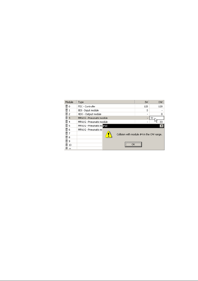
You can modify the addressing individually if you wish to
assign other addresses than those in the default addressing.
· Click directly on the address in the configuration table
and modify the value.
Make sure that the new address is not already assigned,
otherwise you will receive a fault message.
3−20
Fig.3/7: Modify address in the Hardware Configurator
(herewith fault message because address is
already assigned)
Festo P.BE−CPX−FEC−EN en 0404NH
Page 78
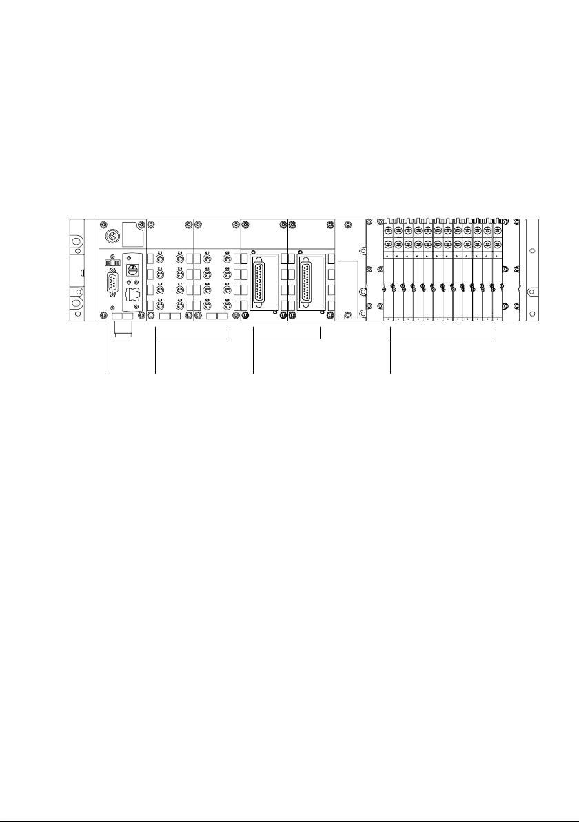
3. General operation (Stand Alone)
3.2.3 Addressing example
Example 1: CPX terminal with default addressing
8DI 4DO
12 3
1 CPX−FEC
2 Digital I/O modules
Fig.3/8: Example 1: CPX terminal with digital and analogue I/O modules as well as MPA
pneumatics
2AI 2AO
4
3 Analogue I/O modules
4 MPA pneumatics
(3 pneumatic modules)
Festo P.BE−CPX−FEC−EN en 0404NH
3−21
Page 79
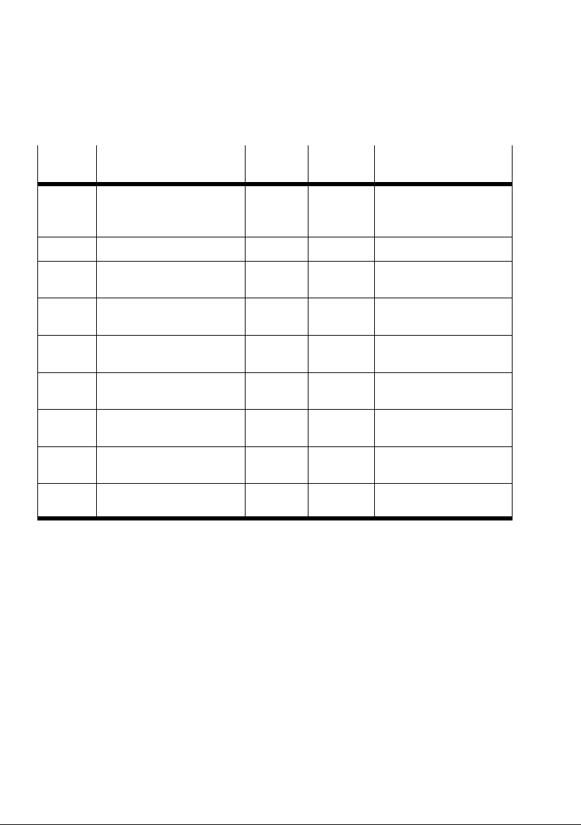
3. General operation (Stand Alone)
Location Module I address O address Remarks
0 CPX−FEC 128 128 The inputs map the posi
1 Digital 8−input module (8DI) 0
2 Digital 4−output module
(4DO)
3 Analogue 2−input module
(2AI)
4 Analogue 2−output module
(2AO)
MPA pneumatic interface
(typeVMPA−FB−EPL−...)
5 MPA pneumatic module
(CPX−type32: 1...8V)
6 MPA pneumatic module
(CPX−type32: 1...8V)
7 MPA pneumatic module
(CPX−type32: 1...8V)
0
64
65
64
Passive module, is not
32
33
34
65
tion of the rotary switch.
The outputs are not used.
shown in the FST
Tab.3/7: Configuration of example 1
3−22
Festo P.BE−CPX−FEC−EN en 0404NH
Page 80
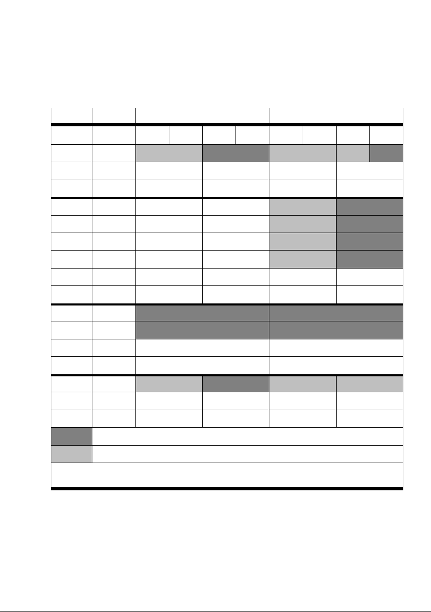
3. General operation (Stand Alone)
Addr. 1)Module Input word Output word
Bit 15 12 11 8 7 4 3 0 15 12 11 8 7 4 3 0
0 8DI / 4DO 8 DI 4 DO
...
31
32 MPA1 8 DO
33 MPA1 8 DO
34 MPA1 8 DO
35 MPA1 8 DO
...
63
64 2AI / 2AO 2 AI (channel 0) 2 AO (channel 0)
65 2AI / 2 AO 2 AI (channel 1) 2 AO (channel 1)
...
127
128 CPX−FEC 8 DI
2)
8 DO
...
255
Dark grey: assigned and used
Light grey: assigned but not used
1)
Word number, automatically assigned by the default addressing
2)
Rotary switch of the CPX−FEC (interrogation of the switch position possible in user program)
Tab.3/8: Address assignment for example 1 (default addressing)
Festo P.BE−CPX−FEC−EN en 0404NH
3−23
Page 81
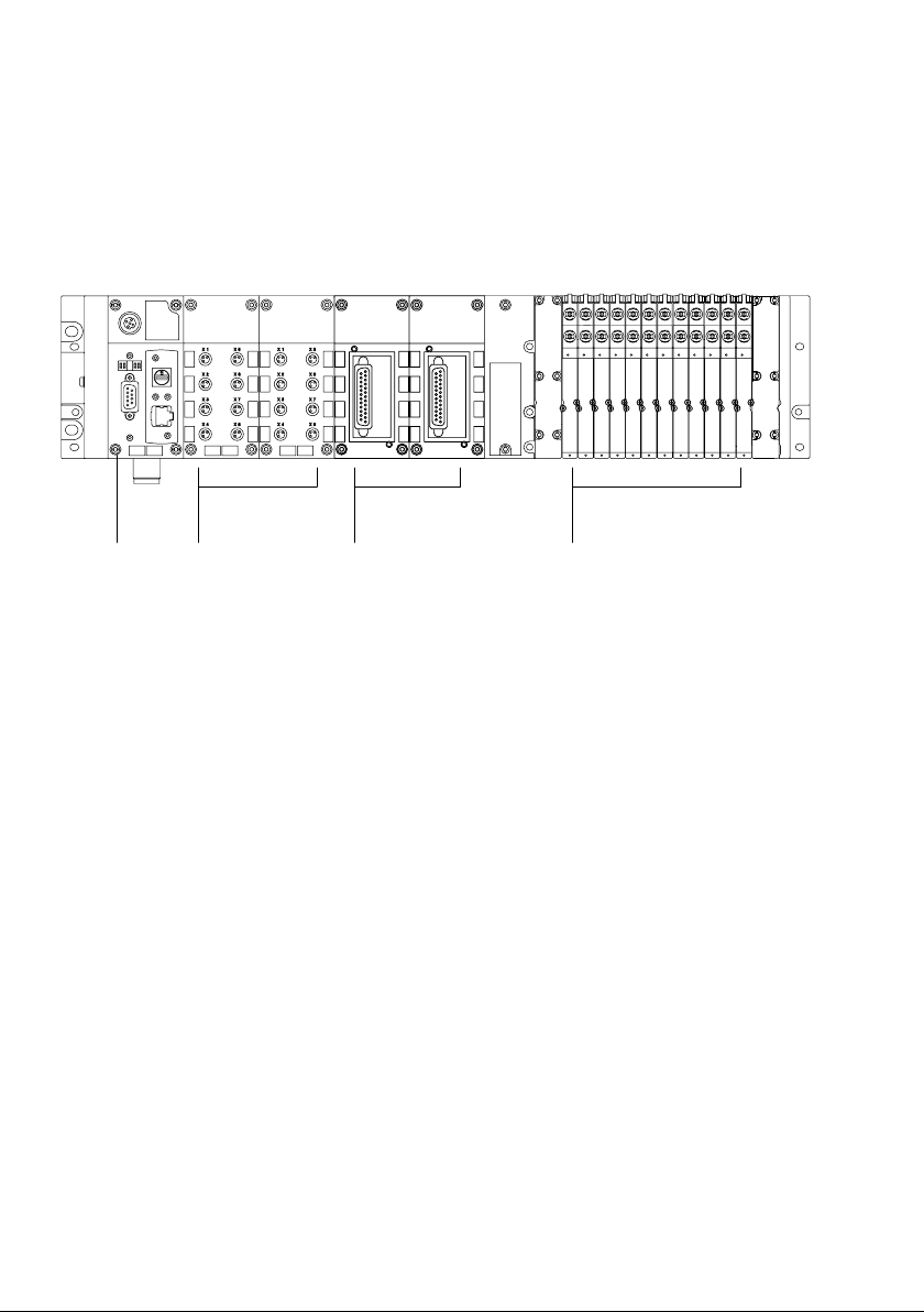
3. General operation (Stand Alone)
Example 2:
CPX terminal with modified addressing (Mapping)
8DI 4DO
12 3
1 CPX−FEC
2 Digital I/O modules
Fig.3/9: Example 2: CPX terminal as in example 1, but addresses modified as follows
2AI 2AO
4
3 Analogue I/O modules
4 MPA pneumatics
(3 pneumatic modules)
For the 2nd. addressing example the addresses have been
modified so that inputs and outputs or valves lie together in
blocks. It is then easier e.g. to understand the composition of
machines (sensors, outputs and
table.
valves) in the addressing
3−24
Festo P.BE−CPX−FEC−EN en 0404NH
Page 82
3. General operation (Stand Alone)
Location Module I address O address Remarks
0 CPX−FEC 128 128 The inputs map the posi
1 Digital 8−input module
(8DI)
2 Digital 4−output module
(4DO)
3 Analogue 2−input module
(2AI)
4 Analogue 2−output module
(2AO)
MPA pneumatic interface
(typeVMPA−FB−EPL−...)
5 MPA pneumatic module
(CPX−type32: 1−8V)
6 MPA pneumatic module
(CPX−type32: 1−8V)
7 MPA pneumatic module
(CPX−type32: 1−8V)
0
10
1
2
11
Passive module, is not
0
1
2
12
tion of the rotary switch.
The outputs are not used.
shown in the FST
Tab.3/9: Configuration of example 2
Festo P.BE−CPX−FEC−EN en 0404NH
3−25
Page 83
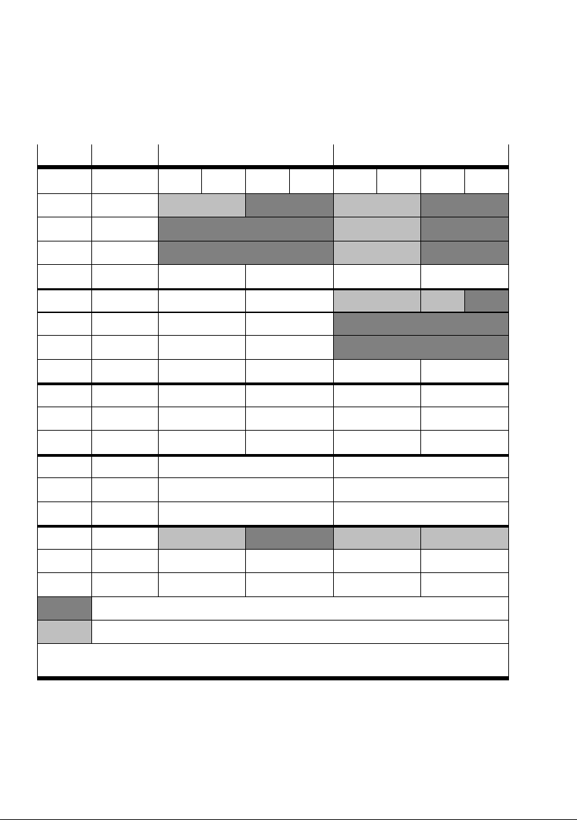
3. General operation (Stand Alone)
Addr. 1)Module Input word Output word
Bit 15 12 11 8 7 4 3 0 15 12 11 8 7 4 3 0
0 8DI / MPA1 8 DI 8 DO
1 2AI / MPA1 2 AI (channel 0) 8 DO
2 2AI / MPA1 2 AI (channel 1) 8 DO
...
10 4DO 4 DO
11 2AO 2 AO (channel 0)
12 2AO 2 AO (channel 1)
...
32
...
63
64
...
127
128 CPX−FEC 8 DI
2)
8 DO
...
255
Dark grey: assigned and used
Light grey: assigned but not used
1)
Word number, automatically assigned by the default addressing
2)
Rotary switch of the CPX−FEC (interrogation of the switch position possible in user program)
Tab.3/10: Address assignment for example 2 (modified addressing)
3−26
Festo P.BE−CPX−FEC−EN en 0404NH
Page 84
3. General operation (Stand Alone)
3.3 Parametrizing
The CPX terminal is supplied with preset parameters. If re
quired, you can set the reaction of the CPX terminal as well as
the reaction of individual modules and channels by parame
trizing.
A distinction is made between the following parametrizings:
System parameters, e.g.: switching off fault messages,
setting reaction times, etc.
Module parameters
(module and channel−specific), e.g.:
Monitoring, settings in the event of faults, settings for
Forcing
Diagnostic memory parameters
A detailed description of the individual parameters and data
as well as basic information on parametrizing can be found in
the CPX system manual (P.BE−CPX−SYS−..).
The module parameters which are available for the various
modules can be
found in the manual for the relevant module
(e.g. manual for CPX pneumatic interface and CPX I/O mod
ules (P.BE−CPX−EA−..).
Festo P.BE−CPX−FEC−E N en 0404NH
3−27
Page 85
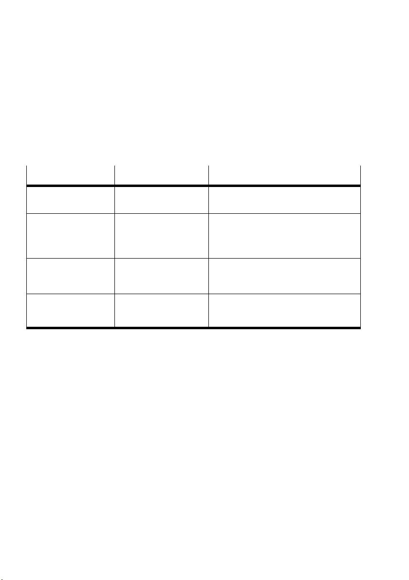
3. General operation (Stand Alone)
Overview of parametrizing possibilities
You can parametrize a CPX terminal with FEC with the Hard
ware Configurator of the FST, with the handheld or via a user
program.
Method
Hardware Configurator
of the FST: offline
Hardware Configurator
of the FST: online
Handheld Parametrizing is carried
User programs Access via function mod
Description Properties
Access to all parameters
of the CPX terminal
Access to all parameters
and data of the CPX ter
minal
out via menu−guided
entries with the handheld.
dules (see appendix C.1)
Comfortable parametrizing via a PC
Parametrizing saved in the project
Comfortable parametrizing via a PC
Parametrizing is saved only locally in the
CPX terminal and is lost with Power
OFF/ON
Parametrizing is saved only locally in the
CPX terminal and is lost with Power
OFF/ON
Program−controlled reaction
Preprocessing possible
Programming very costly
Tab.3/11: Properties of the different parametrizing possibilities
3−28
Festo P.BE−CPX−FEC−EN en 0404NH
Page 86
3. General operation (Stand Alone)
3.3.1 Parametrizing with the handheld
The parameters of the CPX terminal can be read and modified
via a connected handheld. The parametrizings with the Hard
ware Configurator of the FST and the handheld are equal, but
the following applies:
Please note
Parametrizings via the handheld are saved only locally in
the CPX terminal and are lost with Power OFF/ON.
Please note
Further information on parametrizing with the handheld
can be found in the manual for the handheld
P.BE−CPX−MMI−1−DE.
3.3.2 Parametrizing with the Hardware Configurator of the FST
You can parametrize the CPX terminal comfortably with the
Hardware Configurator.
Parametrizing can be undertaken for:
the nominal configuration (offline): Parameters are trans
ferred when the project is loaded.
the actual configuration (online): Parameters can be
transferred immediately. However, parameters are saved
only locally in the CPX terminal and are lost with Power
OFF/ON.
the relevant dialogue has been opened, you can view
When
and modify the individual parameters.
Festo P.BE−CPX−FEC−E N en 0404NH
3−29
Page 87
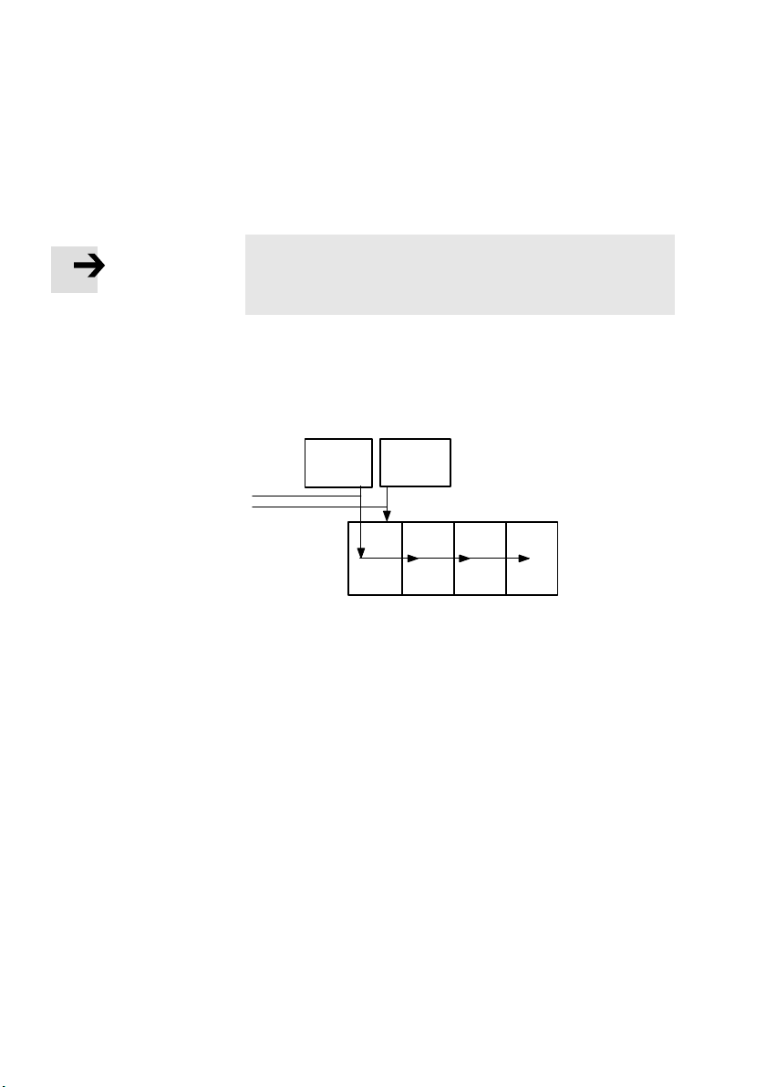
3. General operation (Stand Alone)
Parametrizing when switching on
Please note
There is no system parameter System start" with the
CPX−FEC.
When the CPX terminal is switched on, parametrizing is car
ried out as Start parametrizing" by the project saved in the
CPX−FEC 1. Parametrizings can be carried out as test func
tions with the handheld 2. They are not
saved in the project.
1 Parametrizing
from the FEC
project at start:
1
FST
Configurator
The parameter
set is distributed
2
amongst modules
2 Parametrizing as
a test function
with the handheld
Fig.3/10: Sequence of start parametrizing
Handheld
FEC
Project
3−30
Festo P.BE−CPX−FEC−EN en 0404NH
Page 88
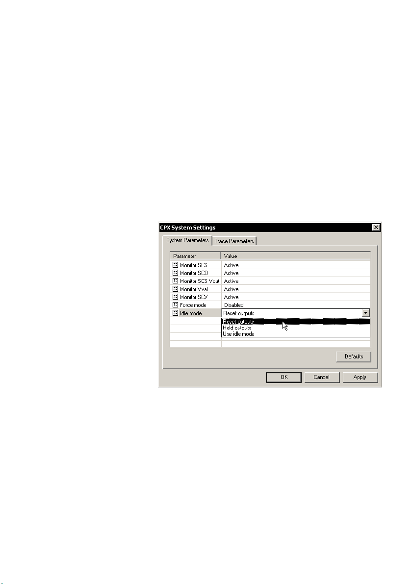
3. General operation (Stand Alone)
Access to the various parameters is explained in the
following.
System parameters
1. Click on System Settings" in the context menu of the
Hardware Configurator.
2. Set the system parameters in the register System Para
meters":
Festo P.BE−CPX−FEC−E N en 0404NH
Fig.3/11: Set the system parameters with the Hardware
Configurator
3−31
Page 89
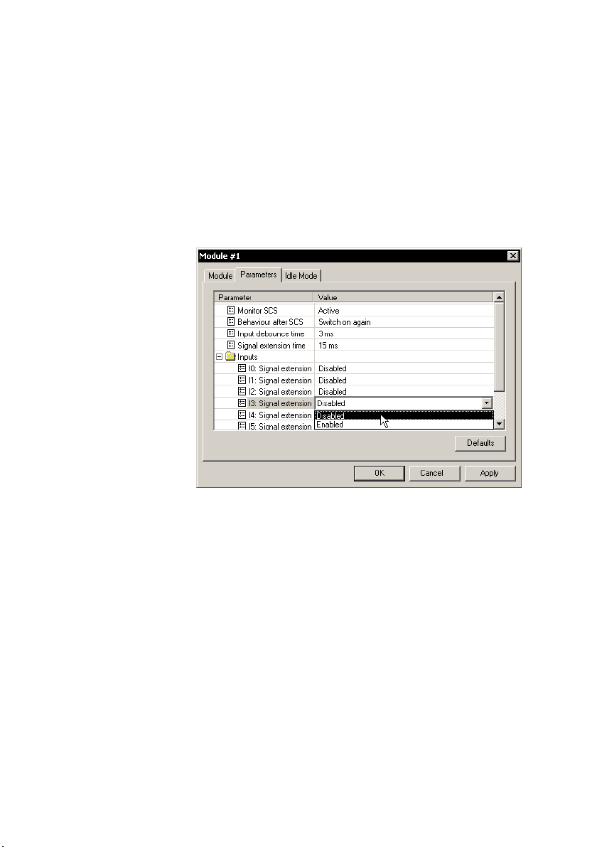
3. General operation (Stand Alone)
Module parameters
1. Double click on the module in the Hardware Configurator
which you wish to parametrize.
2. Set the desired parameters in the register Parameters":
3−32
Fig.3/12: Set the module parameters with the Hardware
Configurator
Festo P.BE−CPX−FEC−EN en 0404NH
Page 90
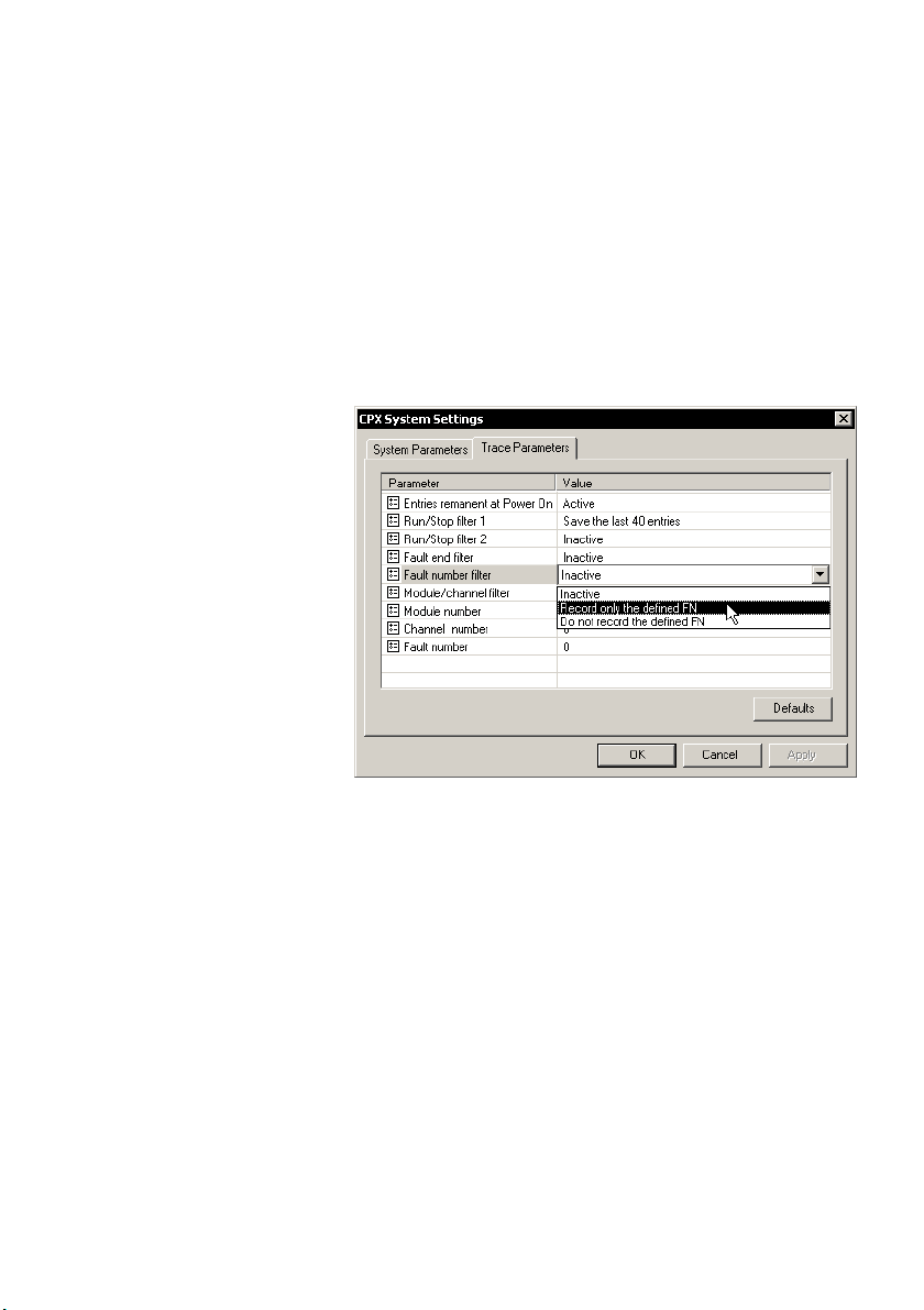
3. General operation (Stand Alone)
Diagnostic memory parameters
1. Click on System Settings" in the context menu of the
Hardware Configurator.
2. Set the diagnostic memory parameters in the register
Trace Parameters".
Festo P.BE−CPX−FEC−E N en 0404NH
Fig.3/13: Set the diagnostic memory parameters with the
Hardware Configurator
3−33
Page 91
3. General operation (Stand Alone)
3.3.3 Parametrizing from a user program
If you wish to modify parameters of the CPX terminals via a
program, you will require special function modules.
Modules
C_ST_rd Read CPX internal parameters and data
C_ST_wr Write CPX internal parameters
C_MP_rd Read general module parameters
C_MD_rd Read module diagnostic data
C_AP_rd Read analogue module parameters
C_AP_wr Write analogue module parameters
Description
Tab.3/12: Function modules for parametrizing the
CPXterminal
Further information on function modules and on parametriz
ing from a user program can be found in:
the appendix C.1
in the FST system manual under Drivers and modules".
3−34
Festo P.BE−CPX−FEC−EN en 0404NH
Page 92
3. General operation (Stand Alone)
3.3.4 Forcing
By forcing you can manipulate input and output signals.
Actual input signals or status changes by program are
ignored and replaced by the force values.
Warning
Depending on the functioning of the machine/system, the
manipulation of signal states may cause serious injury to
human beings or damage to property.
Be very careful when forcing in order to avoid damage.
Forcing inputs Forcing an input does not modify the input signal itself and
cannot be observed at
status of the input is modified internally and in some cases
has an effect on the program. The forced input status is
transferred to the processing image of the inputs. Therefore
the online display of the FST shows the forced input signal.
the relevant status LED. The logical
Forcing outputs In contrast, forcing an
signal and can be observed at the relevant status LED. How
ever, the forced output signal is not transferred to the pro
cessing image of the outputs. The online display of the FST
does not show the forced, physical output signal, but the
status from
Festo P.BE−CPX−FEC−E N en 0404NH
the processing image.
output does modify the actual output
3−35
Page 93
3. General operation (Stand Alone)
Please note
The online display of the FST always shows the valid signal
status in the processing image. Therefore, observe the
following when forcing:
Forced input states are transferred to the processing
image and therefore recognized by the controller. They
are visible in the online display.
Forced output states are not transferred
sing image and are therefore not recognized by the con
troller. They are not therefore represented in the online
display.
You have various possibilities of influencing input or output
signals, e.g. for test purposes:
Forcing via the parametrizing of the CPX terminal
with the online display of the FST
to the proces
3−36
in the user program of the PLC.
If several functions are active at the same time, the following
applies:
force signals have the highest priority.
Forcing with the Hardware Configurator
Forcing is available via the module parametrizing providing
FST online is connected to your CPX terminal.
Please note
If you block or enable forcing globally, all signal states
which are forced will become ineffective or effective im
mediately.
1. Use the right−hand mouse button to click the module for
which you wish to set the force parameters.
2. Select [Properties].
Festo P.BE−CPX−FEC−EN en 0404NH
Page 94
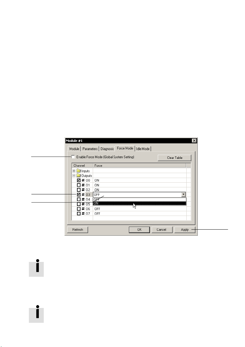
3. General operation (Stand Alone)
3. Select the register Force Mode" (see following diagram).
4. Set the desired value or status for the relevant channel in
the column Force" 1.
5. Enable forcing for the relevant channel by placing a tick in
the column Channel" 2.
6. Activate the Force mode (global system parameter) as
soon as you wish to accept the
7. Accept the settings and close with OK 4.
3
set values 3.
2
1
Fig.3/14: Example: Forcing outputs with the Hardware Configurator
Further information on forcing can be found in the CPX sys
tem manual and in volume 1 of the FST manual (e.g. Forcing
with the online display).
Forcing via CI commands
Information on forcing with CI commands can be found in
appendix D and in the chapter 2 Basic functions of the FST
software" in volume 1 of the FST manual.
Festo P.BE−CPX−FEC−E N en 0404NH
4
3−37
Page 95
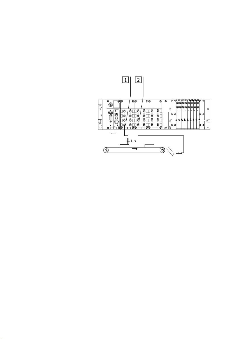
3. General operation (Stand Alone)
3.3.5 Application example for the parametrizing
1
Input with default
parametrizing
21
2 Input with
reduction of the
input debounce
time and increase
in the signal
lengthening time
1. sensor
2. sensor
Fig.3/15: Example of application for parametrizing debounce time and pulse lengthening
(here on the right−hand sensor)
3−38
In the above application packets are transported on a fast−
moving conveyor belt. With the following parametrizing the
registering and processing of the signals has been improved.
Reduction of the input debounce time of 3ms (factory
setting) to 0.1ms:
Shorter signals can also be registered
(applies to the complete module).
Modification of the signal lengthening time to 50ms: The
signal will be registered reliably by the controller.(applies
only to the input channel of the 2nd. sensor).
Festo P.BE−CPX−FEC−EN en 0404NH
Page 96

3. General operation (Stand Alone)
3.4 Programming the CPX−FEC
Use the FST software version 4.1 or higher in order to create
programs for the CPX−FEC, for testing and for commissioning.
User programs and program modules can be created in the
programming languages Statement List (STL) and Ladder
Diagram (LDR).
You will find here a description of the programming prerequi
sites, the programming languages,
operands and operations:
FST system manual
Text book Automation with FST" (supplied with the FST
software)
If you are a beginner in the subject, you should refer to the
relevant basic manuals for more information about the pro
gramming language.
programming techniques,
Festo P.BE−CPX−FEC−E N en 0404NH
When you have planned and structured a project, you can
start with programming.
The following are required:
operands (retentive, non−retentive)
operations (set of commands)
function modules (depending on application).
3−39
Page 97

3. General operation (Stand Alone)
3.4.1 Overview of operands
Operand Design. Range Retentive
Input word IW IW0 ... IW255 No
Input bit I I0.0 ... I255.15 No
Output word OW OW0 ... OW255 can be addressed as word or bit No
Output bit O O0.0 ... O255.15 No
Error word EW 0: No fault, > 0: Error number No
Error status E 0: No fault, 1: Fault
Initial execution flag FI 0: Program cycle > 1, 1: first program cycle
Flag word FW FW0 ... FW9999 Yes
Flag bit F F0.0 ... F9999.15 Yes
Timer T T0 ... T255 (also TP and TW for each timer TON, TOFF) No
Switch−on delay
timer
Switch−off delay
timer
Timer pre−setting TP TP0 ... TP255 Yes
Timer word TW TW0 ... TW255 No
Counter C C0 ... C255 (also as CV and CW for each counter) Yes
Counter pre−setting CP CP0 ... CP255 Yes
Counter word CW CW0 ... CW255 Yes
Register R R0 ... R255 Yes
Function units FU FU0 ... FU31, FU39 ... FU255 per program Yes
Function units FU FU32 ... FU38 per program No
Programs P P0 ... P63 No
Program status PS PS0 ... PS63 No
TON TON0 ... TON255 No
TOFF TOF F0 ... TOFF255 No
(for each program)
No
3−40
Festo P.BE−CPX−FEC−EN en 0404NH
Page 98
3. General operation (Stand Alone)
OperandRetentiveRangeDesign.
Function modules CFM CFM0 ... CFM99 (predefined by Festo) No
Program modules CMP CMP0 ... CMP99 (user−defined) No
Tab.3/13: Operands CPX−FEC
Retentive operands retain their value even when the
controller is switched off.
3.4.2 Overview of operations
Depending on the programming language selected (STL or
LDR), various operands are available for creating a program.
The permitted operations (set of commands) are listed below.
Refer to the FST system manual for a detailed description of
the operations.
Festo P.BE−CPX−FEC−E N en 0404NH
3−41
Page 99
3. General operation (Stand Alone)
STL LDR Meaning
STEP Symbolic step marks are permitted for sequence programs
IF (graphical) Introduces a conditional part
THEN (graphical) Introduces an executive part providing the condition under IF is
OTH RW
/
ELSE
SET S Single−bit operands are set to logical 1", timers, counters or
RESET R Single−bit operands are set to logical 0", timers, counters or
SHIFT Swaps the specified single−bit operand with the value in the
LOAD Single and multibit operands and constants are loaded into the
TO TO Transfers operand 1 to operand 2 in combination with LOAD
NOP NOP Empty operation
N / Negation: Negates operands, i.e. they are interrogated for logical
AND AND Logical command for bit−by−bit AND linking
OR OR Logical command for bit−by−bit OR linking
(graphical) Introduces an alternative executive part if the condition under IF is
fulfilled.
not fulfilled.
programs are started. Instruction follows in an executive part. The
command is saved.
programs are stopped. Instruction follows in an executive part.
The command is saved.
single−bit accumulator
accumulator with this command.
Unconditional in conditional part (IF NOP), substitute symbol in
executive part
zero
EXOR EXOR Logical command for bit−by−bit exclusive OR linking
Tab.3/14: Overview of operations of the CPX−FEC (part 1)
3−42
Festo P.BE−CPX−FEC−EN en 0404NH
Page 100
3. General operation (Stand Alone)
STL LDR Meaning
+ , , * , / + , , * , / Arithmetical commands for addition, subtraction, multiplication
INC I The value of multibit operands is therefore increased by 1
DEC D The value of multibit operands is therefore reduced by 1
SWAP SWAP The higher−value and lower−value bytes in the multibit accumulator
BID BID Converts the contents of the multibit accumulator from BINARY to
DEB DEB Converts the contents of the multibit accumulator from BCD to
SHL SHL All bits in the multibit accumulator are shifted one position to the
SHR SHR All bits in the multibit accumulator are shifted one position to the
ROL ROL In the multibit accumulator all the bits are rotated to the left; the
ROR ROR In the multibit accumulator all the bits are rotated to the right; the
INV INV Complements multibit operands according to the method of the
and division
(incremented)
(decremented)
are swapped.
BCD display.
BINARY display.
left. Bits pushed out to the left are lost.
right. Bits pushed out to the right are lost.
last bit becomes the first, the penultimate becomes the last, etc.
first bit becomes the last, the second becomes the first, etc.
1st. complement.
CPL CPL Complements multibit operands according to the method of the
2nd. complement.
Tab.3/15: Overview of operations of the CPX−FEC (part 2)
Festo P.BE−CPX−FEC−E N en 0404NH
3−43
 Loading...