

Page 1
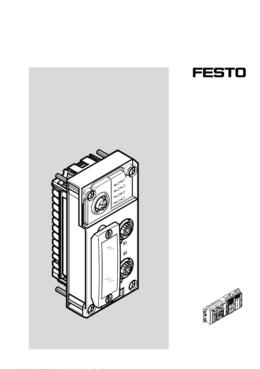
Ter mi na l CPX
Bus node CPX-FB36
Electronics
description
Bus node
Network protocol
EtherNet/IP
Modbus TCP
Industrial Ethernet
2-Port
8024075
en 1309NH
[8024081]
Page 2

Page 3

Contents and general instructions
Original de.......................................
Version en 1309NH.................................
Designation P.BE-CPX-FB36-EN.......................
Order no. 8024075.................................
E (Festo AG & Co., 73726 Esslingen, Germany , 2013)
Internet: http://www.festo.com
E-Mail: [email protected]
Reproduction, distribution and utilisation of this document,
as well as the communication of its contents to others
without explicit authorisation, is prohibited. Offenders will
be liable for damages. All rights are reserved, in particular
the right to file patent, utility model or registered design
applications.
Festo P.BE-CPX-F B36-EN en 1309NH English
I
Page 4

Contents and general instructions
EtherNet/IP®, Modbus®,RSLogix®,RSNetWorx®, SPEEDCON®and TORX
®
are registered trademarks of the respective trademark owners in certain countries.
II
Festo P.BE-CPX -FB36-EN en 1309NH English
Page 5

Contents and general instructions
Ta b l e o f co n te n t s
Intended use VII..........................................................
Target group VIII..........................................................
Service VIII...............................................................
Information regarding this description IX.....................................
Important user information X..............................................
1. Installation 1-1...................................................
1.1 Installation instructions 1-3..........................................
1.1.1 Electrical connection and display elements 1-4...................
1.1.2 Dismantling and mounting of the bus node 1-5...................
1.2 Setting the DIL switches on the bus node 1-7............................
1.2.1 Setting the operating mode and protocol 1-9....................
1.2.2 Setting the diagnostics mode for Remote I/O 1-10.................
1.2.3 Setting the data field size for Remote Controller 1-11...............
1.2.4 Setting IP addressing 1-12....................................
1.3 Connecting to the network 1-13........................................
1.3.1 General information about networks 1-13........................
1.3.2 Overview of connections, network connectors and cables 1-14.......
1.3.3 Network connections of the CPX-FB36 1-17.......................
1.3.4 Setting the IP address 1-18....................................
1.3.5 Advanced network settings 1-22................................
1.4 Ensuring protection classIP65/IP67. 1-23................................
1.5 Power supply 1-24..................................................
2. Preparing for commissioning 2-1.....................................
2.1 EtherNet/IP protocol 2-3............................................
2.1.1 Multicast telegram 2-3.......................................
2.1.2 QuickConnect 2-4...........................................
2.1.3 Device Level Ring protocol (DLR) 2-8...........................
2.2 Modbus/TCP protocol 2-10...........................................
Festo P.BE-CPX-F B36-EN en 1309NH English
III
Page 6

Contents and general instructions
2.3 Notes on commissioning the CPX-FB36 2-11.............................
2.3.1 Requirements for commissioning 2-11...........................
2.3.2 Switching on the power supply 2-12............................
2.3.3 Normal operating status 2-12..................................
2.4 Participants in the netwo rk 2-16.......................................
2.4.1 Participant properties (EDS file) 2-16............................
3. Commissioning 3-1................................................
3.1 Configuration 3-3..................................................
3.1.1 Configuration with EDS file 3-4................................
3.1.2 Configuration with Generic Ethernet Module 3-10..................
3.1.3 Configuration with CPX-FMT 3-15...............................
3.1.4 Configuration in the Remote Controller operating mode 3-19........
3.1.5 Setting up a listen-only connection 3-20.........................
3.2 Parameterisation 3-21...............................................
3.2.1 Parameterisation when switching on (system start) 3-22............
3.2.2 Methods of parameterisation 3-25..............................
3.2.3 Parameterisation via configuration data 3-26.....................
3.2.4 Parameterisation with the operator unit CPX-MMI 3-26.............
3.2.5 Parameterisation in the PLC user program 3-26...................
3.2.6 Parameterisation using CPX-FMT and system start with saved
parameters 3-27.............................................
3.3 Reaction of the outputs in the F ail safe or Idle mode 3-28...................
3.4 Web server 3-29....................................................
3.5 Checklist for commissioning a CPX terminal 3-30..........................
4. Diagnostics 4-1...................................................
4.1 Summary of diagnostics options 4-3...................................
4.2 Diagnostics via LEDs 4-4............................................
4.2.1 CPX-specific LEDs 4-6.......................................
4.2.2 Network-specific LEDs 4-9....................................
4.2.3 Protocol-specific LEDs 4-10....................................
4.3 Diagnostics via status bits 4-12........................................
4.4 Diagnostics via I/O diagnostic interface 4-13.............................
IV
Festo P.BE-CPX -FB36-EN en 1309NH English
Page 7

Contents and general instructions
4.5 Diagnostics via EtherNet/IP 4-15.......................................
4.6 Diagnostics via Modbus TCP 4-16......................................
4.7 Error handling 4-17..................................................
A. Technical appendix A-1.............................................
A.1 Technical data, bus node CPX-FB36 A-3................................
B. Address assignment of the CPX terminal B-1...........................
B.1 Address assignment B-3.............................................
B.2 Addressing B-14....................................................
B.3 Address assignment after extension/conversion B-22......................
C. EtherNet/IP Objects of the CPX-FB36 C-1..............................
C.1 Overview of Ethernet/IP objects C-3...................................
C.2 Objects for network settings C-8......................................
C.2.1 Device Level Ring Object C-8..................................
C.2.2 QoS Object C-9.............................................
C.2.3 TCP/IP Interface Object C-10...................................
C.2.4 Ethernet Link Object C-12.....................................
C.3 Objects for the I/O connection C-13....................................
C.3.1 Assembly Object C-13........................................
C.4 Objects for system data and diagnosis C-18..............................
C.4.1 Identity Object C-18..........................................
C.4.2 Global System Object (for operating mode Remote I/O) C-20........
C.4.3 Status and Diagnostics Object C-23.............................
C.4.4 Diagnostics Trace Object C-24..................................
C.4.5 Diagnostics Trace Status Object C-26............................
C.4.6 General Module Parameter Object C-28..........................
C.4.7 Force parameter C-31........................................
C.4.8 Fail Safe and Idle parameters C-36..............................
C.4.9 Configuration Array Object C-42................................
C.4.10 Slave Size Object (for operating mode Remote Controller) C-42......
Festo P.BE-CPX-F B36-EN en 1309NH English
V
Page 8

Contents and general instructions
C.5 Examples C-43......................................................
C.5.1 Forcing inputs C-43..........................................
C.5.2 Parameterisation with the general Module Parameter Object C-45....
D. Modbus/TCP Objects of the CPX-FB36 D-1.............................
D.1 Overview of Modbus/TCP objects D-3..................................
D.2 Commands and addresses D-3.......................................
D.3 CPX status information (group A) D-4..................................
D.4 Processing data (groups B and D) D-5..................................
D.4.1 Module CPX-FB36 D-5.......................................
D.4.2 Electric modules D-6........................................
D.4.3 Pneumatic modules D-9......................................
D.4.4 Technology module CP interface D-14...........................
D.4.5 Composition of diagnostic data (diagnostic word) D-18.............
D.4.6 Composition of the data of the I/O diagnostic interface D-18.........
D.5 Diagnostic memory (groups C and E) D-20...............................
D.6 Modbus/TCP Objects (group F) D-22....................................
D.6.1 Addressing examples for ModbusTCP D-23.......................
E. Index E-1.........................................................
E.1 Index E-3.........................................................
VI
Festo P.BE-CPX -FB36-EN en 1309NH English
Page 9

Contents and general instructions
Intended use
The bus node CPX-FB36 documented in this description is
exclusively intended for use as a participant in networks with
EtherNet/IP or Modbus TCP protocols.
The CPX terminal must only be used as follows:
– As intended in industrial environments;
– in original status without unauthorised modifications.
– in perfect technical condition.
The limit values specified for pressures, temperatures, electrical data, torques etc. must be observed.
outside of industrial environments, e.g. in commercial and
mixed-residential areas, actions to suppress interference
may have to be taken.
Only the conversions or modifications described in the
documentation supplied with the product are permitted.
If standard ancillary components, such as sensors and actuators, are connected, the specified limits for pressures, temperatures, electrical data, torques, etc. must be complied with.
• Observe the regulations of the trade associations, Ger-
Festo P.BE-CPX-F B36-EN en 1309NH English
man Technical Control Board (TÜV), VDE stipulations or
corresponding national laws and regulations.
VII
Page 10

Contents and general instructions
Target group
This description is intended exclusively for technicians
trained in control and automation technology , who have experience in installing, commissioning, programming and diagnosingparticipantsinnetworkswithEtherNet/IPorModbus TCP protocols.
Service
Please consult your local Festo Service agent if you have any
technical problems.
VIII
Festo P.BE-CPX -FB36-EN en 1309NH English
Page 11
Contents and general instructions
Information regarding this description
Further information regarding EtherNet/IP can be found here:
www.odva.org
General basic information about the mode of operation, assembly, installation and commissioning of CPX terminals can
be found in the CPX system description P.BE.CPX-SYS.
An overview of the structure of the user documentation for
the CPX terminal can be found in the CPX system description
P.B E . CPX - S Y S .
Festo P.BE-CPX-F B36-EN en 1309NH English
IX
Page 12
Contents and general instructions
Important user information
Danger categories
This description includes instructions on the possible dangers
which can occur if the product is used incorrectly. These instructions are marked with a signal word (Warning, Caution,
etc.), printed on a shaded background and marked additionally with a pictogram. A distinction is made between the following danger warnings:
Warning
... means that failure to observe this instruction may result
in serious personal injury or material damage.
Caution
... means that failure to observe this instruction may result
in personal injury or material damage.
Note
... means that failure to observe this instruction may result
in material damage.
In addition, the following pictogram marks passages in the
text which describe activities with electrostatically sensitive
devices:
Electrostatically sensitive devices: Incorrect handling may
cause damage to devices.
X
Festo P.BE-CPX -FB36-EN en 1309NH English
Page 13
Contents and general instructions
Marking of special information
The following pictograms mark passages in the text which
contain special information.
Pictograms
Information:
Recommendations, tips and references to other information
sources.
Accessories:
Specifications on necessary or useful accessories for the
Festo product.
Environment:
Information on the environmentally friendly use of Festo
products.
Text designations
• Bullets denote activities that may be carried out in any
1. Numerals denote activities that must be carried out in the
– Arrowheads indicate general lists.
Festo P.BE-CPX-F B36-EN en 1309NH English
desired order.
sequence specified.
XI
Page 14
Contents and general instructions
The following product-specific terms and abbreviations are
used in this description:
Term/abbreviation
160
d
A0
h
AA, AO Analogue output
AE, AI Analogue input
BOOTP Dynamic protocol for automatic assignment of IP addresses (Boot
Bus nodes A bus node connects the CPX terminal to the fieldbus or network; it
C Output
CEC Codesys controller, e.g. CPX-CEC, applicable for control, configuration
CODE SYS Controller Development System
CP Compact Performance
CP module Collective term for the various modules which can be incorporated in
CPX-CP interface Interface for connecting decentrally arranged CP modules to a CPX
CPX-FMT Festo Maintenance Tool for configuration and parameterisation of CPX
Significance
Decimal numbers are marked in part by a low-set “d”.
Hexadecimal numbers are marked by a low-set “h”.
protocol, predecessor of DHCP).
transmits control signals to the connected CPX and pneumatic modules
and monitors their operational capability.
and commissioning of CPX terminals.
the CP system (decentralised installation system).
terminal.
terminals.
CPX-MMI Operator unit for commissioning and service purposes.
Tab . 0/1: CPX-specific terms and abbreviations – part 1
XII
Festo P.BE-CPX -FB36-EN en 1309NH English
Page 15
Contents and general instructions
Term/abbreviation Significance
CPX modules Collective term for electric modules which can be incorporated into a
CPX terminal Complete system consisting of various CPX modules with or without
DHCP Dynamic protocol for automatic assignment of IP addresses (Dynamic
DI Digital input (or “Discrete input”)
DIL switches Miniature switches; dual-in-line switches usually consist of several
DO Digital output (o r “Discrete output”)
EtherNet/IP Communicationprotocol for connecting various devices in a network.
FEC Front End Controller, e.g. CPX-FEC, can be used as:
Function module Collective term for modules with additional functions, e.g.
I Input
CPX terminal: bus nodes, I/O modules and function modules
(technology modules).
CPX modules provide, among other things, electrical inputs and
outputs for connectingsensors and actuators.
CPX modules form the electrical side of the CPX terminal.
pneumatics modules.
Host Configuration Protocol).
switch elements which can be used to implement settings.
– stand-alone system controller (PLC, stand alone operating mode)
– system controller (PLC, remote controller operating mode)
– fieldbus slave (remote I/O operating mode)
CPX-CP-interface, Front End Controller (CPX-FEC) and CODESYS
controller (CPX-CEC); function modules are also known as technology
modules.
I/O diagnostics interface Bus-independent, bi-directional diagnostic interface at I/O level;
enables access to the internal data of the CPX terminal.
I/O module Collective term for CPX modules that provide analogue or digital inputs
and outputs.
I/Os Analogue or digital inputs and outputs.
Tab . 0/2: CPX-specific terms and abbreviations – part 2
Festo P.BE-CPX-F B36-EN en 1309NH English
XIII
Page 16
Contents and general instructions
Term/abbreviation Significance
I/O signal Input/output signal of an I/O module; also referred to as a process
Modbus TCP Communication protocol via TCP/IP in automationtechnology.
Pneumatics interface Interface between CPX modules and pneumatics modules within a CPX
Pneumatic modules Collective term for the pneumatics modules which can be integrated
Status bits CPX-internal status information (common diagnostic messages) which
Technology module Function module
signal.
terminal.
The pneumatics interface is used functionally for the electrical side of
the CPX terminal.
into a CPX terminal.
Pneumatics modules provide, among other things, outputs (working
ports) for connecting actuators, e.g. cylinders.
Pneumatics modules form the pneumatic side of the CPX- terminal.
are provided as input signals on the fieldbus of the control system
(optional function)
Tab . 0/3: CPX-specific terms and abbreviations – part 3
XIV
Festo P.BE-CPX -FB36-EN en 1309NH English
Page 17
Contents and general instructions
Data type Quantity Range of values Description
ARRAY —
1)
— Structure with identical
data types
BOOL 1bit 0“False”and1“True” Logical data type
BYTE 8bit 00h…FF
h
Bit field
DWORD 32 bit 00000000h… FFFFFFFFhBit field
DINT 32 bit -2147483648 …
Signed Double Integer
2147483647
INT 16 bit -32.768 … 32.767 Signed Integer
Padded EPATH Max. 12 bytes Logical segments of a
path specification
SINT 8bit -128 … 127 Signed Short Integer
STRING 8 bit/characters — String
SHORT_STRING 8 bit/characters +
8 bit length
— String with max. 255
characters
specification
STRUCT —
1)
— Structure of any data
types
UDINT 32 bit 0 … 4294967296 Unsigned Double Integer
UINT 16 bit 0 … 65.536 Unsigned Integer
USINT 8bit 0 … 256 Unsigned S hort Integer
WORD 16 bit 0000h… FFFF
1) Dependent on the data types used.
Tab. 0/4: Data types used
Festo P.BE-CPX-F B36-EN en 1309NH English
h
Bit field
XV
Page 18

Contents and general instructions
XVI
Festo P.BE-CPX -FB36-EN en 1309NH English
Page 19

Installation
Chapter 1
Installation
1-1Festo P.BE-CPX-F B36-EN en 1309NH English
Page 20

1. Installation
Ta b l e o f co n te n t s
1. Installation 1-1...................................................
1.1 Installation instructions 1-3..........................................
1.1.1 Electrical connection and display elements 1-4...................
1.1.2 Dismantling and mounting of the bus node 1-5...................
1.2 Setting the DIL switches on the bus node 1-7............................
1.2.1 Setting the operating mode and protocol 1-9....................
1.2.2 Setting the diagnostics mode for Remote I/O 1-10.................
1.2.3 Setting the data field size for Remote Controller 1-11...............
1.2.4 Setting IP addressing 1-12....................................
1.3 Connecting to the network 1-13........................................
1.3.1 General information about networks 1-13........................
1.3.2 Overview of connections, network connectors and cables 1-14.......
1.3.3 Network connections of the CPX-FB36 1-17.......................
1.3.4 Setting the IP address 1-18....................................
1.3.5 Advanced network settings 1-22................................
1.4 Ensuring protection classIP65/IP67. 1-23................................
1.5 Power supply 1-24..................................................
1-2
Festo P.BE-CPX -FB36-EN en 1309NH English
Page 21
1. Installation
1.1 Installation instructions
Warning
Switch off the following components before undertaking
installation and/or maintenance work:
– Compressed air supply
– Operating voltage supply for electronics/sensors
– Load voltage supply for outputs/valves
In this way, you can avoid:
– sudden uncontrolled movements of loose tubing
– unexpected movements of the connected actuators
– undefined switching states of the electronics
They will help you avoid damage to the electronics.
Information about mounting the CPX terminal can be found in
the CPX system description ( P .BE-CPX-SYS).
Festo P.BE-CPX-F B36-EN en 1309NH English
Caution
The CPX bus node contains electrostatically sensitive
devices.
• Therefore, do not touch any components.
• Observe the handling specifications for electrostatically
sensitive devices.
Note
Use protective caps or blanking plugs to seal unused connections. You will then comply with protection class
IP65/IP67 ( section 1.4).
1-3
Page 22
1. Installation
1.1.1 Electrical connection and display elements
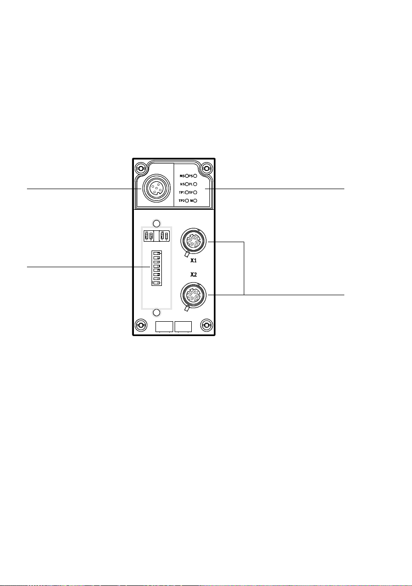
The following connection, setting and display components
can be found on the CPX bus node CPX-FB36:
4
3
1
2
1 Protocol and CPX-specific LEDs
2 Network connections X1 and X2
(one 4-pin M12 socket each, D-coded)
Fig. 1/1: Connection, setting and display components on the bus node CPX-FB36
1-4
3 DILswitchwithtransparentcover
4 Service interface for operator unit
(CPX-MMI; V24 interface) und USB
adapter (for CPX-FMT)
Festo P.BE-CPX -FB36-EN en 1309NH English
Page 23
1. Installation
1.1.2 Dismantling and mounting of the bus node
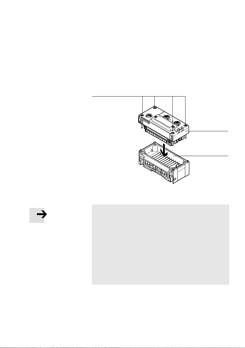
The bus node is mounted in an interlinking block of the CPX
terminal.
1 Bus node
CPX-FB36
3
2 Interlinking block
with contact rails
3 Tor x T10 scre ws
Fig. 1/2: Dismantling / mounting the bus node
Note
• Check the start behaviour of the CPX terminal before
replacing the bus node.
If the Modify LED (M) illuminates or flashes permanently
after the system start, “System start wi th saved parametrisation and saved CPX expansion” is set or “Force” is active. In this case parameterisation is not created automatically by the higher-order system when replacing the bus
node or CPX terminal during servicing.
• Therefore, verify which settings are required before re-
placement and restore these settings after replacement.
1
2
Festo P.BE-CPX-F B36-EN en 1309NH English
1-5
Page 24
1. Installation
Dismantling the bus node 1. Loosen the four screws of the bus node with a Torx
screwdriver size T10.
2. Pull the bus node carefully and without tilting away from
the contact rails of the interlinking block.
Note
• Always use the correct screws for the interlinking block,
which depend on whether the block is made of metal or
plastic:
–forplastic interlinking blocks:
self-tapping screws
–formetal interlinking blocks:
screws with metric thread.
Both types of screws are enclosed respectively when ordering
the bus node as a single part.
Mounting the bus node 1. Check the seal and the sealing surfaces between the bus
node and interlinking block.
2. Place the bus node in the interlinking block without
tilting. Make sure that the corresponding slots with the
contacting terminals on the bottom of the bus node are
above the contact rails.
3. Push the bus node carefully and without tilting as far as
possible into the interlinking block.
4. Set the screws so that the self-cutting threads can be
used.
5. Tighten the screws alternately in diagonally opposite
sequence with a Torx screwdriver (size T10). Tightening
torque:0.9…1.1 Nm.
1-6
Festo P.BE-CPX -FB36-EN en 1309NH English
Page 25
1. Installation
1.2 Setting the DIL switches on the bus node
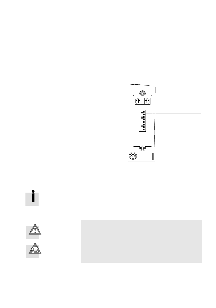
TheDILswitchesonthebusnodeareusedtochangethe
following settings.
1 DIL switch
group 1:
Operating mode
and protocol
12
2 DIL switch
group 2:
Diagnostics mode
for remote I/O or
number of I/O
bytes for Remote
Controller
3 DIL switch
group 3:
IP addressing
3
Fig. 1/3: DIL switches on the bus node
Changes to the DIL switches only take effect when the bus
node is restarted.
The DIL switch cover must be removed to change the settings.
Caution
The CPX bus node contains electrostatically sensitive
devices.
• Do not therefore touch any contacts.
• Observe the handling specifications for electrostatically
sensitive devices.
This will help you avoid damage to the bus node electronics.
Festo P.BE-CPX-F B36-EN en 1309NH English
1-7
Page 26
1. Installation
Procedure
1. Switch off the power supply.
2. Remove the DIL switch cover.
3. Change the DIL swi tch settings ( section1.2.1 ff.).
4. Mount the cover.
Remove the DIL switch cover
1. Unscrew the two mounting screws in the switch cover.
2. Lift off the cover.
Mounting the DIL switch cover
1. Place the cover carefully on the bus node.
1-8
Note
• Make sure that the seal is seated correctly.
2. Tighten the two mounting screws at first by hand and
then with a max. tightening torque of 0.4 Nm.
Festo P.BE-CPX -FB36-EN en 1309NH English
Page 27
1. Installation
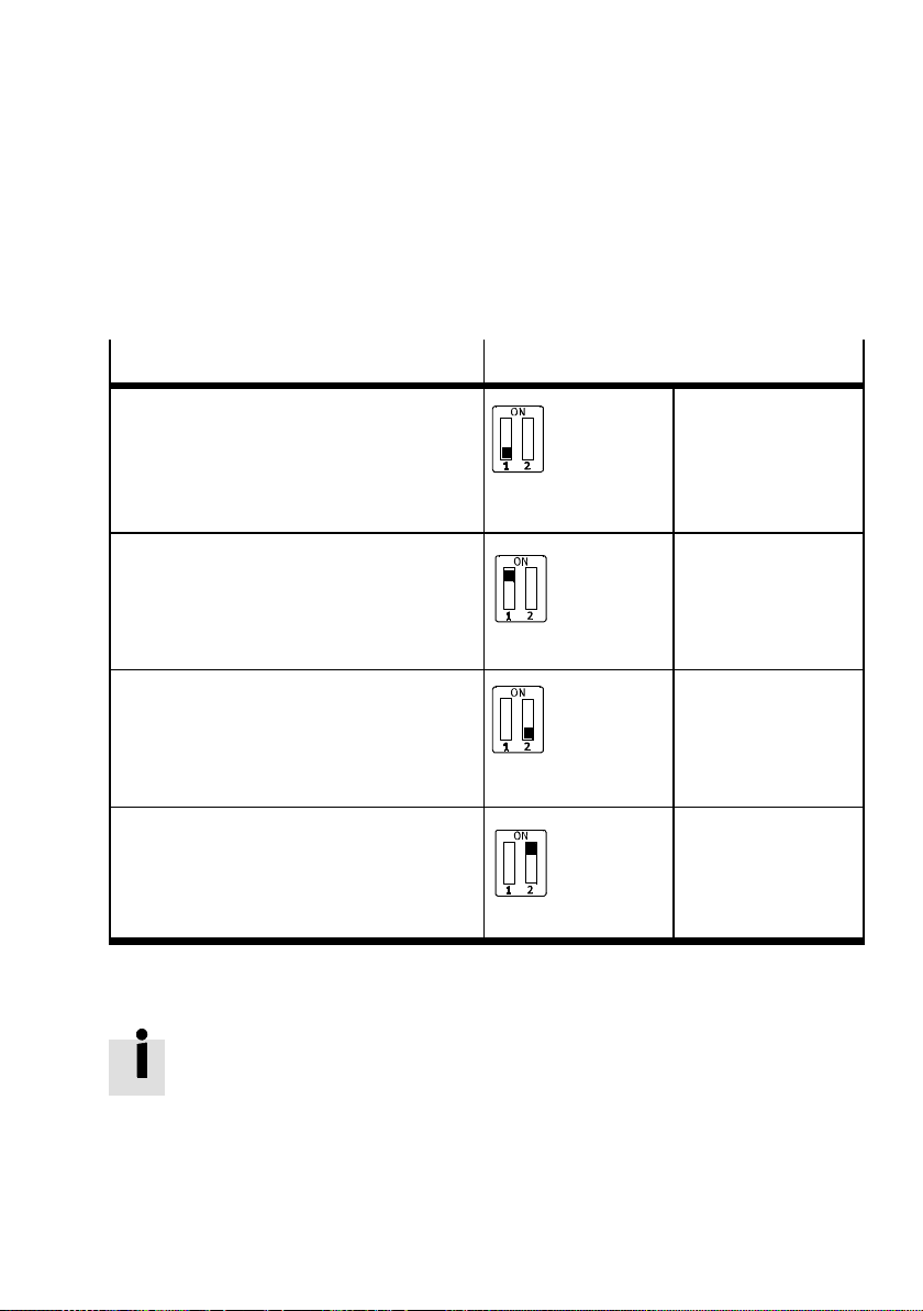
1.2.1 Setting the operating mode and protocol
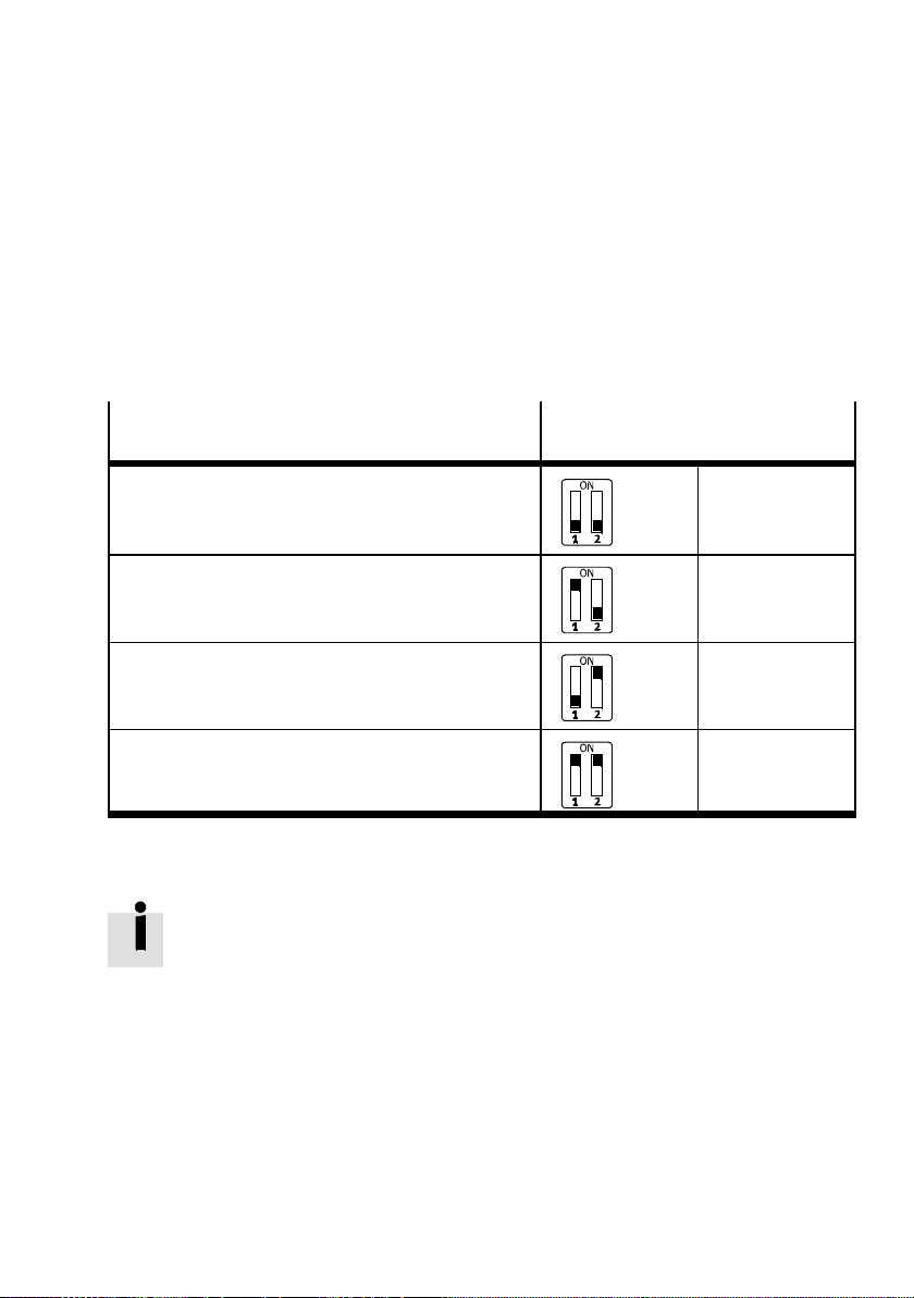
• Use DIL switch group 1 ( Fig. 1/1 1).
Operating mode and protocol
Remote I/O operating mode
All functions of the CPX terminal are controlled
directly via EtherNet/IP or Modbus TCP.
A CPX-FEC or CPX-CECthat may be integrated
into the CPX terminal works as a passive function
module without controller.
Operating mode Remote Controller
A CPX-FEC or CPX-CECintegrated into the CPX
terminal takes over I/O control.
EtherNet/IP protocol
The CPX terminal uses the EtherNet/IP protocol.
Modbus TCP protocol
The CPX terminal uses the Modbus/TCP
protocol.
Setting of DIL switch group 1
Tab. 1/1: Setting the operating mode and protocol
DIL 1.1: OFF
(factory setting)
DIL 1.1: ON
DIL 1.2: OFF
(factory setting)
DIL 1.2: ON
Setting the diagnostics mode is required for the Remote I/O
operating mode ( chapter1.2.2).
Setting the data field size is required for the Remote Controller operating mode ( chapter1.2.3).
Festo P.BE-CPX-F B36-EN en 1309NH English
1-9
Page 28
1. Installation
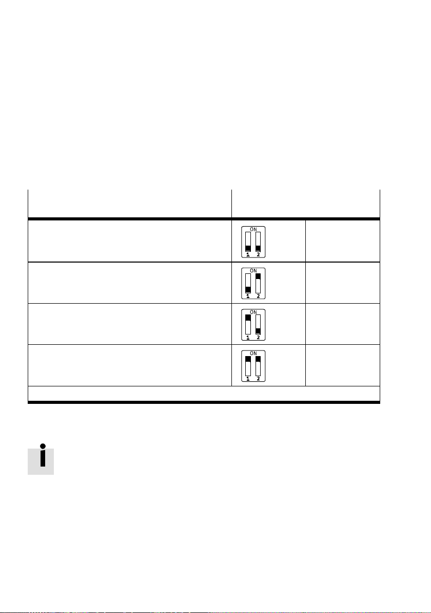
1.2.2 Setting the diagnostics mode for Remote I/O
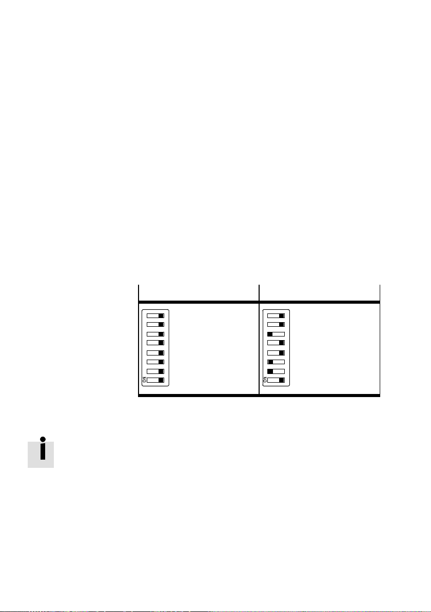
• Use DIL switch group 2 ( Fig. 1/1 2).
The functions of these DIL switches depend on the set operating mode of the CPX terminal ( Tab. 1/1).
Diagnostics mode for the Remote I/O operating
Setting of DIL switch group 2
mode
The I/O diagnostic interface and the status bits are
switched off
(+ 0 I/O bits)
Status bits are switched on
(++16E-bits(8used))
The I/O diagnostic interface is switched on
(+ 16 I/O bits)
Reserved 2.1: ON
1) The I/O diagnostic interface occupies an additional 16 I/O bits.
1)
2.1: OFF
2.2: OFF
(factory setting)
2.1: OFF
2.2: ON
2.1: ON
2.2: OFF
2.2: ON
Tab. 1/2: Setting of the diagnostics mode for the Remote I/O operating mode
During subsequent activation of the diagnostics module
(status bits or I/O diagnostics interface), the CPX-internal I/O
image can be displaced.
The system controller carries out this adjustment automatic-
ally. Manual manipulation, e.g. reconfiguration of the CPX
terminal or manual adaptation of the hardware and network
configuration are not required.
1-10
Festo P.BE-CPX -FB36-EN en 1309NH English
Page 29
1. Installation
1.2.3 Setting the data field size for Remote Controller
• Use DIL switch group 2 ( Fig. 1/1 2).
The functions of these DIL switches depend on the set operating mode of the CPX terminal ( Tab. 1/1).
Number of I/O bytes for the Remote Controller
Setting of DIL switch group 2
operating mode
8byteI/8byteOfor communicationof the bus node
with the CPX-FEC or CPX-CEC.
Reserved 2.1: ON
16 byte I/16 byte O for communication of the bus node
with the CPX-FEC or CPX-CEC.
Reserved 2.1: ON
2.1: OFF
2.2: OFF
(factory setting)
2.2: OFF
2.1: OFF
2.2: ON
2.2: ON
Tab. 1/3: Setting the number of I/O bytes for the Remote Controller operating mode
The assignment of the I/O addresses and diagnostics addresses can be changed as needed by using the configuration
and programming software (e.g. Rockwell RSLogix).
Festo P.BE-CPX-F B36-EN en 1309NH English
1-11
Page 30
1. Installation
1.2.4 Setting IP addressing
• Use DIL switch group 3 ( Fig. 1/1 3).
By using DIL switch group 3 you can set the type of addressing or the I P address of the bus node.
• Set all slide switches to “OFF”, so that when the bus node
is switched on it receives a dynamic or saved IP address
( section1.3.4).
• Use DIL switches 1 ... 8 to define a binary number other
than 0 and 255.
This number is used as part of the IP address when turning on the bus node.
Dynamic/saved addressing
Setting:
All switches OFF
(factory setting)
1234 5678
Fixed addressing
Setting:
Host ID of
the IP address
1234 5678
Tab. 1/4: Settings for addressing type or IP address
Dynamic addressing is set via DHCP/BOOTP by default.
IfalloftheswitchesinDILswitchgroup3aresetto“ON”
when switching on the bus node, all IP parameters will be
reset to the factory setting.
• Note the detailed information on addressing in sec-
tion 1.3.4.
1-12
Festo P.BE-CPX -FB36-EN en 1309NH English
Page 31
1. Installation
1.3 Connecting to the network
1.3.1 General information about networks
Note
Sub-assemblies with Ethernet interfaces should only be
operated in networks if all connected network components
are supplied by PELV power supplies or integrated power
supplies with equivalent protection.
Installation guidelines
The installation guidelines can be obtained via the OD VA user
organisation:
Internet: http://www.odva.org
Observe the instructions in these documents.
Use of switches and routers
The switch integrated in the bus node permits division of the
network into several segments.
With use of additional switches and routers, the network can
be divided into additional segments. Thus, it is possible to
structure the network and realise greater network expansions.
Independent of the network structure, the expansion of a
network segment must not exceed certain connection
lengths.
– Copper connecting cable:
Festo P.BE-CPX-F B36-EN en 1309NH English
(Ethernet twisted pair cable, 22 AWG):
max. 100 m between network participants
1-13
Page 32
1. Installation
Switches and routers for Industrial Ethernet are available on
the market from various companies. There are many IP20,
IP65 or IP67 components.
– Unmanaged Switches:
for small network solutions with a low network load or
minimal requirements for deterministics
– Managed Switches:
for comprehensive network solutions, with diagnostics
and monitoring functions
1.3.2 Overview of connections, network connectors and cables
Note
Faulty installation and high transmission rates may cause
data transmission errors as a result of signal reflections
and attenuations.
Transmission errors can be caused by:
– faulty screened connection
–branches
– transmission over distances which are too long
– inappropriate cables
Observe the cable specification!
Bus nodes
CPX-FB36 2xM12socket,D-coded,female,4-pin,
Internet: www.festo.com/catalogue/
Connection technology Network connectors
corresponding to IEC 61076-2
Festo c onnector,
type NECU-M-S-D12G4-C2-ET
Tab . 1/5: Overview of connection technology and network plugs
1-14
Festo P.BE-CPX -FB36-EN en 1309NH English
Page 33
1. Installation
RJ45 to M12 converter
For EtherNet/IP installations, it may be necessary to change
between RJ45- and M12 connection technology.
Example:
Connections between devices in the control cabinet with RJ45
connection and IP65/IP67 devices with M12 connection.
Cable specification
Use shielded Industrial Ethernet lines of category
Cat 5/Cat 5e or higher ( Tab. 1/6).
Crossover detection The CPX bus node supports the “Crossover detection” func-
tion (Auto-MDI/MDI-X). Patch cables or crossover cables can
be optionally used for connecting the bus node to your network or a PC. The CPX-FB36 automatically adapts the protective circuit of network connections X1 and X2.
• Use suitable cables when the crossover detection function
Festo P.BE-CPX-F B36-EN en 1309NH English
Note
If the “QuickConnect” function has been activated ( section 2.1.2 ), the crossover detection function is not available.
In this case the CPX-FB36 sets the pin allocation of network
connection X2 to “Crossover”.
is deactivated:
– Crossover cable with the same port assignment as the
connected equipment
– Patch cable with a different port assignment to the
connected equipment
1-15
Page 34
1. Installation
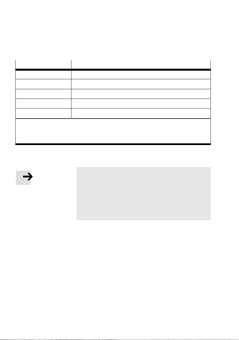
CPX-FB36 + ...D12G4... Cable specification
Cable type Ethernet twisted pair cable, shielded (Shielded Twisted Pair, STP)
Transmission class Category Cat 5/Cat 5e (link class)
Cable diameter 6 ... 8 mm
Wire cross section 0.14 ... 0.75 mm2;22AWG
Connection length max. 100 m
1) Length c orresponding to specification for EtherNet/IP networks (EtherNet/IP Installation Guide),
based on ISO/IEC 11801, ANSI/TIA/EIA-568 (
Internet: www.odva.org
2) Required for max. connection length between network participants
1)
2)
section 1.3.1)
Tab . 1/6: Cable specification overview
Note
When mounting the CPX terminal on a moving part of a
machine:
• Make sure that the network cables are provided with
strain relief.
• Comply with the corresponding regulations set out in
EN 60204 part 1.
1-16
Festo P.BE-CPX -FB36-EN en 1309NH English
Page 35
1. Installation
1.3.3 Network connections of the CPX-FB36
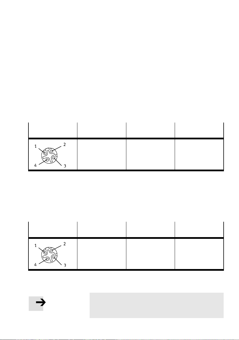
There are two 4-pin, D-coded M12 sockets on the bus node
for the network connection.
The sockets are compatible with SPEEDCON® plugs.
Network connection X1
• Connect the CPX-FB36 via connection X1.
M12 socket
EtherNet/IP
Pin allocation Signal Pin equivalent with
RJ45 plug
1. TX+
2. RX+
3. TX–
4. RX–
Housing
Transmitted data+
Received data+
Transmitted data–
Received data–
Screening, FE
1
3
2
6
Tab. 1/7: Pin allocation of network connection X1 on the CPX-FB36 (M12 4-pin)
Network connection X2
• Connect the CPX-FB36 to the next device via connec-
tion X2.
M12 socket
EtherNet/IP
Pin allocation Signal Pin equivalent with
RJ45 plug
1. RX+
2. TX+
3. RX–
4. TX–
Housing
Received data+
Transmitted data+
Received data–
Transmitted data–
Screening, FE
3
1
6
2
Tab. 1/8: Pin allocation of network connection X2 on the CPX-FB36 (M12 4-pin)
Festo P.BE-CPX-F B36-EN en 1309NH English
Note
When crossover detection is activated, the bus node automatically exchanges the RX and TX connections.
1-17
Page 36
1. Installation
Connection with plug from Festo
The CPX terminal is connected to the network with Festo
plugs, type NECU-M-S-D12G4-C2-ET.
The plugs are designed for network cables measuring
6...8 mm in diameter.
To comply with protection class IP65/IP67:
• Use Festo plugs
• Seal unused interfaces ( section1.4)
1.3.4 Setting the IP address
The IP address of bus node CPX-FB36 is alternatively set via:
– Dynamic addressing via DHCP/BOOTP (factory setting)
– Saved network settings
1-18
– Addressing via DIL switch
Note
When changes are made to the network settings of the
CPX-FB36 via DIL switch, the Modify LED “M” flashes yellow.
• Perform a restart of the bus node so that the modified
network settings are applied.
Festo P.BE-CPX -FB36-EN en 1309NH English
Page 37

1. Installation
Dynamic addressing via DHCP/BOOTP
• Make sure that a DHCP/BOOTP server is located in the
network.
To set the dynamic addressing:
1. SetallswitchesofDILswitchgroup3toOFF
( Tab. 1/4).
2. Alternatively activate DHCP/BOO TP in the bus node via:
– Operator unit CPX-MMI
– Programme “Festo Maintenance Tool” (CPX-FMT)
– Programme “BOOTP-DHCP Server” from Rockwell
Automation
Saved network settings
The CPX-FB36 offers the option to save the network settings
in a non-volatile memory of the bus node. DHCP/BOOTP is
thereby deactivated.
1. SetallswitchesofDILswitchgroup3toOFF
2. Alternatively change the network settings via:
Use this setting to activate the storage of network settings in
a non-volatile memory of the bus node.
Festo P.BE-CPX-F B36-EN en 1309NH English
( Tab. 1/4).
– Operator unit CPX-MMI
– Programme “Festo Maintenance Tool” (CPX-FMT)
– Programme “BOOTP-DHCP Server” from Rockwell
Automation
1-19
Page 38
1. Installation
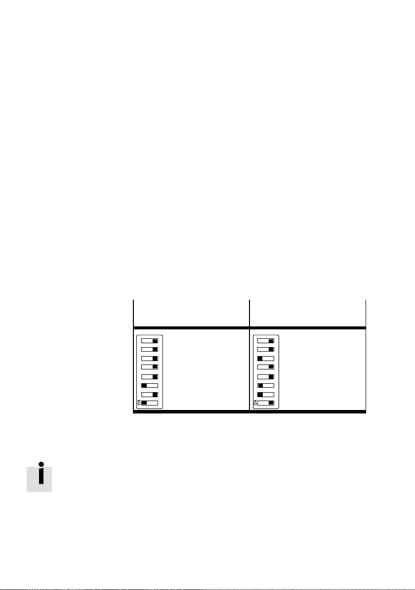
Addressing via DIL switch
Tip When addressing via DI L switch the bus node obtains a fixed
IP address.
This setting is recommended for test purposes during commissioning or for small networks.
The IP address of the bus node consists of 4 octets:
– Octets1...3(savedinthebusnode)
– Octet 4 through the setting of DIL switch group 3
( Tab. 1/9)
• Use DIL switch group 3 to define a binary number
between1and254.Thisnumberisthenusedasthe4th
octet of the IP address when turning on the bus node.
1-20
Example with IP address:
192.168.001.005
20+22=
1+4=
5
1234 5678
Example with IP address:
192.168.001.038
21+22+25=
2+4+32=
38
1234 5678
Tab. 1/9: Examples of fixed values for the 4th octet of the
IP address (binary coded)
IfalloftheswitchesinDILswitchgroup3aresetto“ON”
when switching on the bus node, all IP parameters will be
reset to the factory setting.
Festo P.BE-CPX -FB36-EN en 1309NH English
Page 39

1. Installation
Factory settings of the CPX-FB36
IP address - octet 1 ... 3 192.168.1
IP address - octet 4 0
Network mask 255.255.255.0
Gateway 0.0.0.0
1) Dynamic addressing via DHCP/BOOTP
1)
Tab. 1/10: Factory settings of the CPX-FB36
• Alternatively change the first 3 octets of the IP address
via:
– Operator unit CPX-MMI
– Festo Maintenance Tool CPX-FMT
– Access to corresponding EtherNet/IP objects
The network mask and gateway are set by using the corresponding CPX parameters.
Festo P.BE-CPX-F B36-EN en 1309NH English
1-21
Page 40

1. Installation
1.3.5 Advanced network settings
The following settings for the network connection can be implemented via Ethernet link objects ( appendixC.2.4).
Automatic setting When set to the factory setting the CPX-FB36 automatically
detects the baud rate and duplex mode.
Baud rate
Setting via attribute 6 (Forced Interface Speed) of the Ethernet link object:
–10Mbit/s
– 100 Mbit/s
Duplex mode
1-22
Setting via attribute 6 (Control Bits, Bit 1) of the Ethernet link
object:
– Half-Duplex
– Full-Duplex
Festo P.BE-CPX -FB36-EN en 1309NH English
Page 41
1. Installation
1.4 Ensuring protection classIP65/IP67.
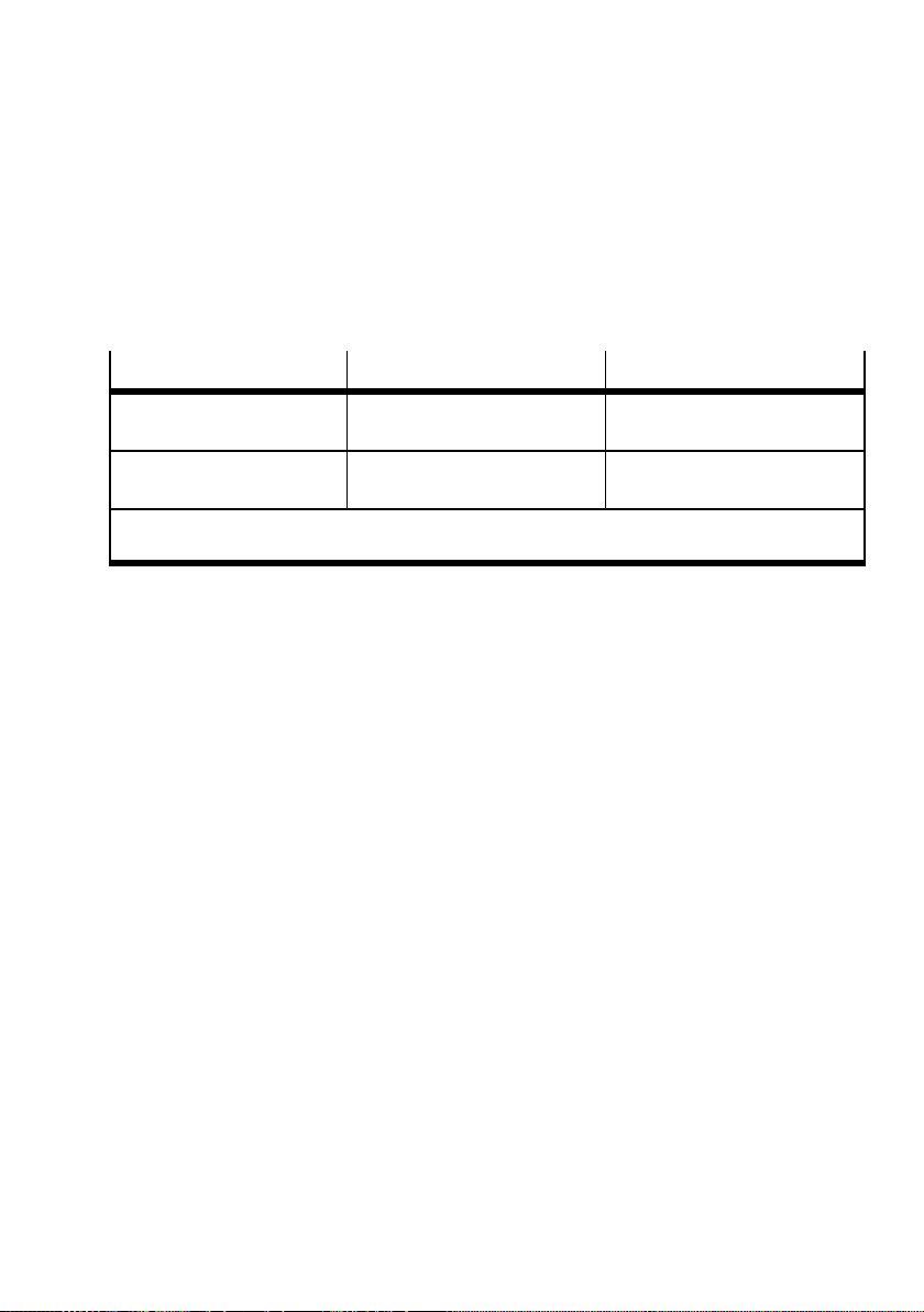
In order to comply with protection class IP65/IP67, seal any
unused sockets with the appropriate plugs or cover caps.
Connection
X1, X2 (M12) Festo c onnector,
Service interface (M12) for
CPX-MMI + CPX-FMT
1) if connection is not used
2) included in scope of delivery, alwayscover unused connection
Port IP65/IP67 Cover IP65/IP67
type NECU-M-S-D12G4-C2-ET
Connecting cable and plug
of the CPX-MMI or CPX-FMT
Cover cap from Festo,
type ISK-M12
Cover cap from Festo,
type ISK-M12
Tab . 1/11: Connections and covers for protection class IP65/IP67
1)
2)
Festo P.BE-CPX-F B36-EN en 1309NH English
1-23
Page 42
1. Installation
1.5 Power supply
Warning
Electric shock
Injury to people, damage to the machine and system
• For the electrical power supply, use only PELV circuits in
accordance with IEC 60204-1 (Protective Extra-Low
Voltage, PELV).
• Observe the general requirements in accordance with
IEC 60204-1 for PELV circuits.
• Useonlyvoltagesourcesthatguaranteeareliableelec-
tric disconnection of operating and load voltage in accordance with IEC 60204-1.
• Always connect all circuits for the operating and load
voltage supplies U
EL/SEN,UVAL
and U
OUT
.
The current consumption of a CPX terminal depends on the
number and type of integrated modules and components.
1-24
Observe the information on power supply ( electrical connection) as well as on the earthing measures to be carried out
( potential equalisation) contained in the CPX system description.
Festo P.BE-CPX -FB36-EN en 1309NH English
Page 43

Preparing for commissioning
Chapter 2
Preparing for commissioning
2-1Festo P.BE-CPX-F B36-EN en 1309NH English
Page 44

2. Preparing for commissioning
Ta b l e o f co n te n t s
2. Preparing for commissioning 2-1.....................................
2.1 EtherNet/IP protocol 2-3............................................
2.1.1 Multicast telegram 2-3.......................................
2.1.2 QuickConnect 2-4...........................................
2.1.3 Device Level Ring protocol (DLR) 2-8...........................
2.2 Modbus/TCP protocol 2-10...........................................
2.3 Notes on commissioning the CPX-FB36 2-11.............................
2.3.1 Requirements for commissioning 2-11...........................
2.3.2 Switching on the power supply 2-12............................
2.3.3 Normal operating status 2-12..................................
2.4 Participants in the network 2-16.......................................
2.4.1 Participant properties (EDS file) 2-16............................
2-2
Festo P.BE-CPX -FB36-EN en 1309NH English
Page 45

2. Preparing for commissioning
2.1 EtherNet/IP protocol
EtherNet/IP is an industrial Ethernet protocol, which is predominantly used in automation technology.
The EtherNet/IP protocol is activated with DIL
switch 1.2 = OFF. The bus node is then identified with the
designation: FB36 - EtherNet IP Remote-IO
After switching the protocol ( section 1.2.1) the following
unmodified parameters are available:
– IP address
–Diagnosticsmode
– System parameters
The DIL switch function remains unchanged.
Retentive bus-specific parameters are onl y active if the relevant protocol is selected ( section 1.2.1).
Parameterisation examples can be found in appendix C.5.
2.1.1 Multicast telegram
EtherNet/IPusesIPMulticasttelegramsasstandardfor
transferring process data. An advantage of Multicast compared to Unicast is that a telegram can be received by multiple participants.
Simple switches, however, cannot distinguish to which participant a Multicast telegram is to be transferred. Therefore,
these switches send the Multicast telegrams to all devices in
the network.
This results in an EtherNet/IP participant receiving numerous
unnecessary telegrams, which must then be discarded from
the device. This can reduce the response times of the participants. The demand on the network bandwidth increases.
Festo P.BE-CPX-F B36-EN en 1309NH English
2-3
Page 46

2. Preparing for commissioning
This does not pose a problem for smaller networks; the performance for larger networks, however, can be improved with
the following functions and/or protocols.
– Use of switches wi th “IGMP snooping”
– Segmentation of the network
Switches with “IGMP snooping”
By using an IGMP (Internet Group Management Protocol) the
switches are able to decide to which devices the various Multicast telegrams are transferred. This allows unnecessary
Multicast traffic to be avoided.
• Activate this function in all switches/routers used.
• Configure at least one switch so that cyclical IGMP quer-
ies are sent. The IGMP snooping function cannot work
properly without these IGMP queries.
2.1.2 QuickConnect
2-4
Segmentation of the network
• Split the machine into smaller network segments. This can
be realised without changing the network cabling, for
example, by using VLANs.
The EtherNet/IP function QuickConnect (QC) enables a quicker initialisation of the CPX terminal and a fast connection setup to the EtherNet/IP master.
QuickConnect is commonly used for applications with a tool
change, for which the downtime should be minimised by the
disconnection and connection of devices.
Festo P.BE-CPX -FB36-EN en 1309NH English
Page 47
2. Preparing for commissioning
Note
QuickConnect only works if this function is supported by
all participating devices.
• Make sure that intermediate switches and routers in
Using QuickConnect:
• Deactivate Auto-Negotiation in the bus node for both net-
• Deactivate Auto-Negotiation and crosso ver detection for
your network support this function.
work connections X1 and X2.
– Baud rate = 100 Mbit/s
– Duplex mode = Full-Duplex
Attribute 6
of the Ethernet link object (Inter-
d
face Control).
the corresponding network connection of the counterpart
station (e.g. switch connection).
• Activate QuickConnect via attribute 12 of the T CP/IP inter-
• Activate QuickConnect in the PLC or in the control pro-
Simplified configuration of QuickConnect on CPX-FB36:
• Set the CPX parameter “IP configuration” to
Selecting this setting activates QuickConnect and deactivates
Auto-Negotiation for both network connections.
Festo P.BE-CPX-F B36-EN en 1309NH English
– Baud rate for connection of the counterpart station =
100 Mbit/s
– Duplex mode = Full-Duplex
face object. (The QuickConnect function in the bus node is
in a deactivated state when delivered.)
gram.
“With saved parameters and QuickConnect”.
2-5
Page 48
2. Preparing for commissioning
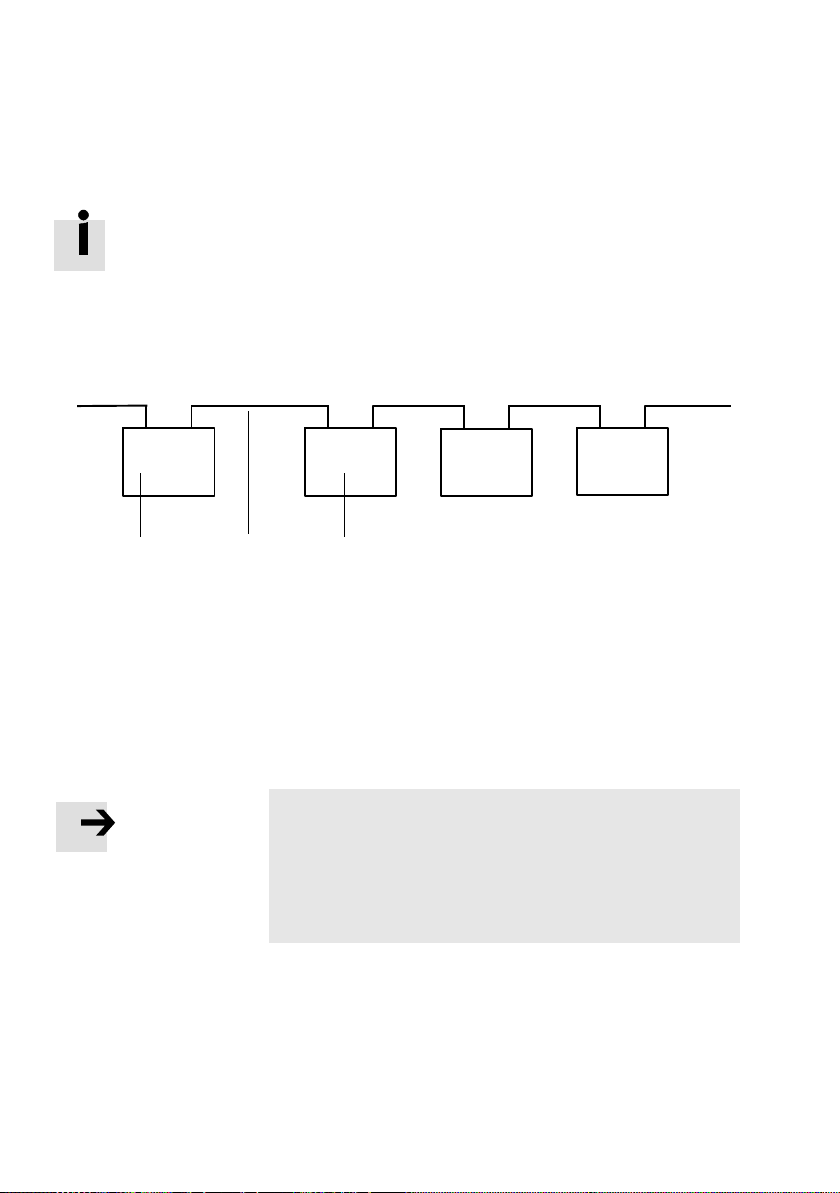
Crossover detection is automatically deactivated in the bus
node when Auto-Negotiation is deactivated.
NetworkconnectionX1runsintheMDI-modehereandnetworkconnectionX2runsintheMDI-Xmode.
This allows a line topology to be constructed with patch
cables.
TP1
TP2
X1
MDI
X2
MDIX
X1
MDI
123
1 PLC or switch
3 I/O device (e.g.B. CPX-FB36)
2 Patch cable
Fig. 2/1: QuickConnect li ne topology with patch cables
The bus node corresponds to a Class A device of the EtherNet/IP specification. When switched on, the bus node requires less than 350 ms to accept a TCP connection.
Note
Due to the rapid establishment of the TCP connection, the
detection of already used IP addresses (IP Address Conflict Detection, ACD) is not executed completely. This can
lead to multiple assigned IP addresses only being detected
at a late stage. This can impair the function of the network.
X2
MDIX
X1
MDI
X2
MDIX
2-6
Festo P.BE-CPX -FB36-EN en 1309NH English
Page 49
2. Preparing for commissioning
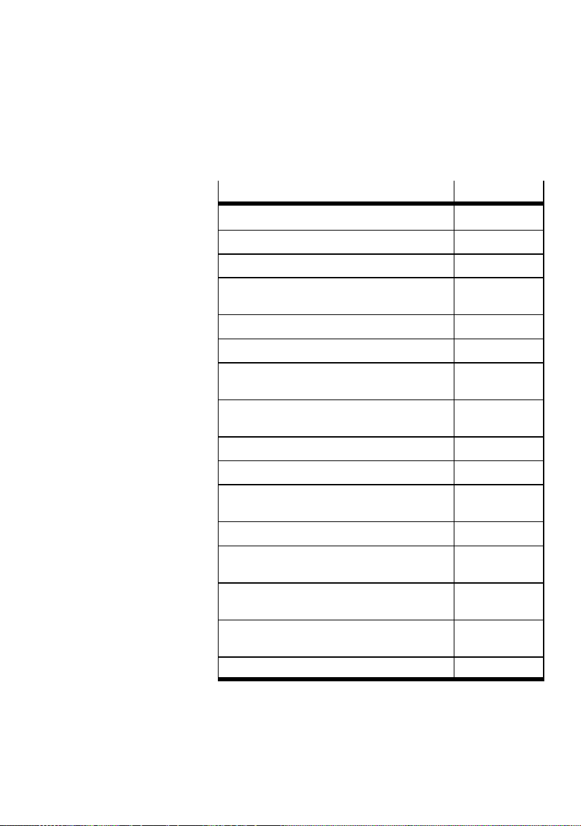
QuickConnect is available for the following modules.
CPX modules
Bus node CPX-FB36 CPX-FB36
Digital 4-off input module CPX-4DE
Digital 8-off input module CPX-8DE
Digital 8-off input module with
channel diagnostics
Digital 8-off input module, n-switching CPX-8NDE
Digital 16-off input module CPX-16DE
Digital 16-off input module with channel diagnostics
Digital 16-off input module
with terminal strip
Digital 4-off output module CPX-4DA
Digital 8-off out put module CPX-8DA
Digital 8-off out put module,
high-current variant
Digital 8-off input/output module CPX-8DE-8DA
Digital 16-off input/output module with terminal
strip
Type
CPX-8DE-D
CPX-16DE-D
CPX-L-16DE16-KL-3POL
CPX-8DA-H
CPX-L-8DE-8DA16-KL-3POL
Analogue 2-off input module
(voltage/current)
Analogue 2-off output module
(voltage/current)
Analogue 4-off input module (current) CPX-4AE-I
Tab. 2/1: CPX modules which support QuickConnect
Festo P.BE-CPX-F B36-EN en 1309NH English
CPX-2AE-U-I
CPX-2AA-U-I
2-7
Page 50
2. Preparing for commissioning
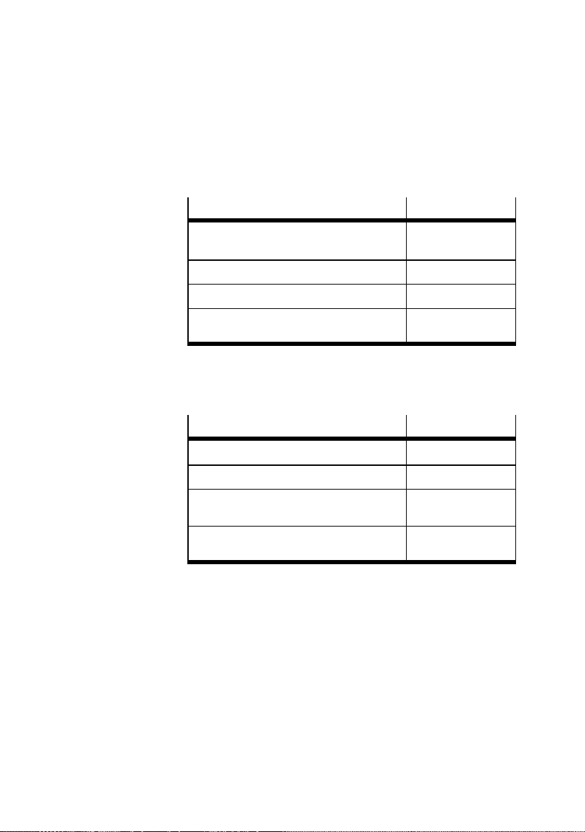
QuickConnect is available for the following pneumatics interfaces and modules.
Pneumatic interfaces
Pneumatics interface for VTSA or
VTSA-F pneumatics
Pneumatics interface f or MPA-S valves VMPA-FB-EPL-...
Pneumatics interface for MPA-F valves VMPAF-FB-EPL-...
Pneumatics interface for MPA-L valves VMPAL-FB-EPL-...
Type
VABA-10S6-x1
VMPAL-EPL-CPX
Tab. 2/2: Pneumatics interfaces which suppor t
QuickConnect
Pneumatic modules
MPA1 pneumatic module VMPA1-FB-EM...-8
MPA2 pneumatics module VMPA2-FB-EM...-4
MPA1 pneumatics module with diagnostic
function
MPA2 pneumatics module with diagnostic
function
Type
VMPA1-FBEM...-D2-8
VMPA2-FBEM...-D2-8
Tab. 2/3: Pneumatics modules which support
QuickConnect
2.1.3 Device Level Ring protocol (DLR)
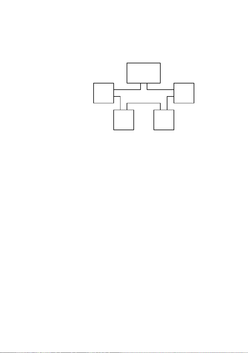
The Device Level Ring protocol (DLR) allows multiple devices
to be operated in a ring topology.
Requirements
All DLR devices feature an integrated Ethernet switch with at
least 2 external ports and suppor t the DLR Protocol.
2-8
Festo P.BE-CPX -FB36-EN en 1309NH English
Page 51
2. Preparing for commissioning
Ring
Supervisor
Ring
Node 4
Ring
Node 3
Ring
Node 2
Ring
Node 1
Fig. 2/2: Device Level Ring topology, example
The availability of the network can be increased by using ring
topology as there are redundant communication paths
between two devices. A cable or communication fault
between two devices will therefore not result in communication failure. Only two faults in a ring will lead to a malfunction.
A ring always consists of at least one ring supervisor and any
number of ring nodes.
• Only use DLR-compatible devices in a ring.
Otherwise, the time required for automatic elimination of
a fault may be adversely affected.
• Operate the bus node as a ring node either in a beacon-
based or announce-based configuration.
Operation as a ring supervisor is not possible. This function is normally executed by an EtherNet/IP scanner.
The DLR protocol is configured via the DLR object (class
code 47
Festo P.BE-CPX-F B36-EN en 1309NH English
).
h
2-9
Page 52

2. Preparing for commissioning
2.2 Modbus/TCP protocol
Modbus is an open communication protocol based on the
master-slave architecture. This is a standard for communication via TCP/IP in automation technology.
The Modbus/TCP protocol is activated with DIL
switch 1.2 = ON. The bus node is then identified with the designation: FB36-MB - Modbus TCP Remote-IO
After switching the protocol ( section 1.2.1) the following
unmodified parameters are available:
– IP address
–Diagnosticsmode
– System parameters
The DIL switch function remains unchanged.
2-10
Retentive bus-specific parameters are onl y active if the relevant protocol is selected ( section 1.2.1).
The configuration options via Modbus TCP correspond to
those via EtherNet/IP.
Exception: EtherNet/IP objects cannot be accessed via Modbus TCP.
In order to configure the CPX terminal for Modbus/TCP, you
will require the Modbus addresses of the data and of the I/Os
of the CPX terminal ( appendix D).
Addressing examples can be found in appendix D.6.1.
Festo P.BE-CPX -FB36-EN en 1309NH English
Page 53
2. Preparing for commissioning
2.3 Notes on commissioning the CPX-FB36
Configuration of the CPX terminal demands a very accurate
procedure, as different configuration specifications are sometimes necessary for each station in the network, due to the
modular structure.
Detailed instructions and further information can be found in
the documentation or online help for the controller or control
program.
Note
Bus node CPX-FB36 can be used on all EtherNet/IP or
Modbus/TCP controllers.
The following section describes the configuration and
commissioning procedure using the example of
Rockwell/Allen-Bradley controllers (PLC) via the Rockwell
RSLogix software platform.
2.3.1 Requirements for commissioning
– Installation of the bus node is complete ( chapter 1)
– The DIL switches of the bus node are set correctly.
– All connecting cables are connected and checked.
Festo P.BE-CPX-F B36-EN en 1309NH English
2-11
Page 54
2. Preparing for commissioning
2.3.2 Switching on the power supply
Warning
Before switching on:
• Make sure that the requirements for commissioning
have been met. Also observe section 3.1.2, especially
regarding the DIL switch setting.
During operation:
• Do not alter the DIL switch setting. This will prevent acci-
dental and uncontrolled movements of the connected
actuators and undefined switching states of the electronics.
Note
• Please observe the switching-on instructions in the
manual for your controller.
2.3.3 Normal operating status
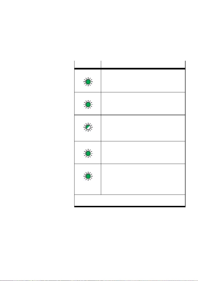
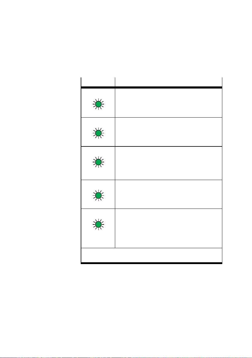
When the CPX terminal is switched on the status LEDs
( Fig. 4/1) indicate the operating status and correct function of the bus node and of fieldbus communication as a function of the configuration.
– Bus node not configured Tab. 2/4
– Bus node configured and higher-order PLC is in stop
mode Tab. 2/5
– Bus node configured and higher-order PLC is in run mode
Tab. 2/6
Information on diagnostics using the LED displays can be
found in section 4.2.
2-12
Festo P.BE-CPX -FB36-EN en 1309NH English
Page 55
2. Preparing for commissioning
Bus node not configured
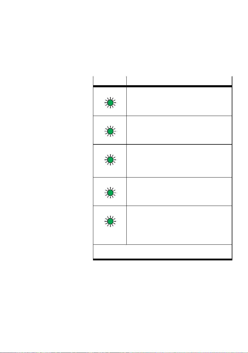
LED display Status and significance
MS illuminates green:
– Device is ready to operate
PS illuminates green:
– Voltage supply (Power System, PS) is OK
– Operating voltage present
(in the approved range)
NS flashes green:
– Fieldbus communication present (“Online”
operating status), but not configured.
This is correct in this case because the bus node
is not configured.
1) Display dependent on monitoring and signal from the connected
Tab. 2/4: Status LEDs after switching on –
Festo P.BE-CPX-F B36-EN en 1309NH English
device.
PL illuminates green:
– Load voltage present (in the approved range)
TP1/TP2 illuminates green:
– Device is correctly connected to the bus node
– Internal communication between bus node and
device 1 or device 2 is error free
– Operating and load voltage present (in the ap-
proved range)
1)
bus node not configured
1)
2-13
Page 56
2. Preparing for commissioning
Bus node configured - PLC in stop mode
LED display Status and significance
MS illuminates green:
– Module status (MS) is error free
PS illuminates green:
– Voltage supply (Power System, PS) is OK
– Operating voltage applied
(in the approved range)
NS illuminates green:
– Network stat us (NS) is error free (“Online”
operating status)
– Communication with the fieldbus and with the
PLC is OK
2-14
PL illuminates green:
– Load voltage present (in the approved range)
TP1/TP2 illuminates green:
– Device is correctly connected to the bus node
– Internal communication between bus node and
device 1 or device 2 is error free
– Operating and load voltage present (in the
approved range)
1) Display dependent on monitoring and signal from the connected
device.
1)
Tab. 2/5: Status LEDs after switch on – bus node
configured,PLCinstop mode
Festo P.BE-CPX -FB36-EN en 1309NH English
1)
Page 57
2. Preparing for commissioning
Bus node configured - PLC in run mode
LED display Status and significance
MS illuminates green:
– Module status (MS) is error free
PS illuminates green:
– Voltage supply (Power System, PS) is OK
– Operating voltage applied
(in the approved range)
NS illuminates green:
– Network status (NS) is error free (“Online”
operating status)
– Communication with the fieldbus and with the
PLC is OK
1) Display dependent on monitoring and signal from the connected
Tab. 2/6: Status LEDs after switch on – bus node
Festo P.BE-CPX-F B36-EN en 1309NH English
device.
PL illuminates green:
– Load voltage present (in the approved range)
TP1/TP2 illuminates green:
– Device is correctly connected to the bus node
– Internal communication between bus node and
device 1 or device 2 is error free
– Operating and load voltage present (in the
approved range)
1)
configured,PLCinrun mode
1)
2-15
Page 58

2. Preparing for commissioning
2.4 Participants in the network
When using the CPX terminal as a new network participant for
the first time, the configuration program is to be informed of
certain network properties.
These network properties are integrated into the participant
properties.
2.4.1 Participant properties (EDS file)
The participant properties are predominantly managed by the
configuration program in a list or library e. g. EDS library (EDS
for electronic data sheet).
The following options are available for expanding an EDS library:
– Installing EDS files
2-16
– Entering participant properties manually
– Importing participant properties
When the CPX terminal has been registered as a potential
network participant, it can be added to a network.
Festo P.BE-CPX -FB36-EN en 1309NH English
Page 59

Commissioning
Chapter 3
Commissioning
3-1Festo P.BE-CPX-F B36-EN en 1309NH English
Page 60

3. Commissioning
Ta b l e o f co n te n t s
3. Commissioning 3-1................................................
3.1 Configuration 3-3..................................................
3.1.1 Configuration with EDS file 3-4................................
3.1.2 Configuration with Generic Ethernet Module 3-10..................
3.1.3 Configuration with CPX-FMT 3-15...............................
3.1.4 Configuration in the Remote Controller operating mode 3-19........
3.1.5 Setting up a listen-only connection 3-20.........................
3.2 Parameterisation 3-21...............................................
3.2.1 Parameterisation when switching on (system start) 3-22............
3.2.2 Methods of parameterisation 3-25..............................
3.2.3 Parameterisation via configuration data 3-26.....................
3.2.4 Parameterisation with the operator unit CPX-MMI 3-26.............
3.2.5 Parameterisation in the PLC user program 3-26...................
3.2.6 Parameterisation using CPX-FMT and system start with saved
parameters 3-27.............................................
3.3 Reaction of the outputs in the F ail safe or Idle mode 3-28...................
3.4 Web server 3-29....................................................
3.5 Checklist for commissioning a CPX terminal 3-30..........................
3-2
Festo P.BE-CPX -FB36-EN en 1309NH English
Page 61

3. Commissioning
3.1 Configuration
A CPX terminal with bus node CPX-FB36 can be configured
using various methods.
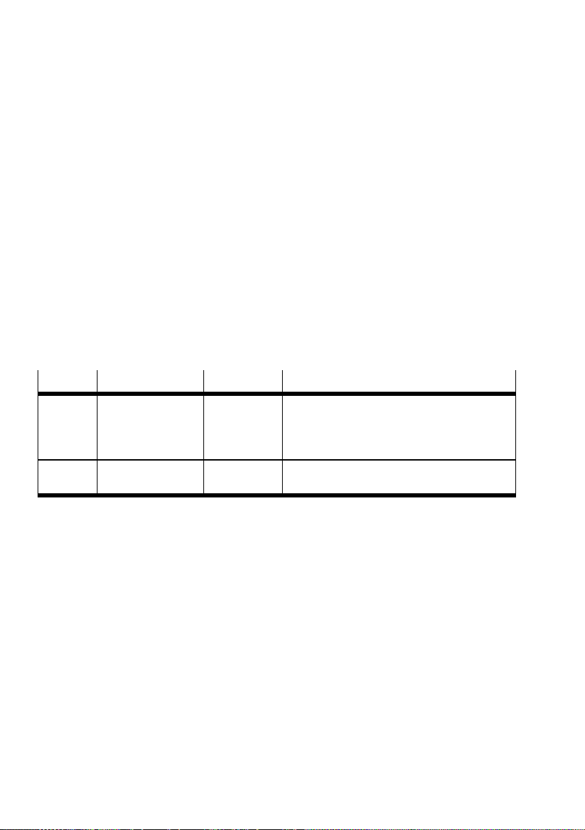
Method
Configuration with EDS
file
section 3.1.1
Configuration with
Generic Ethernet
Module
section 3.1.2
Configuration with
CPX-FMT
section 3.1.3
Description Benefits Disadvantages
Installationof
participant properties
for the CPX terminal in
the “RSLogix 5000”
configuration program.
Creation of a new
participant and manual
configuration in the
“RSLogix 5000”
configuration program.
Export of the CPX
terminal settings by
CPX-FMT and import of
the settings to the
“RSLogix 5000”
configuration program.
Tab. 3/1: Configuration methods
– With the exception
of the I/O data
length, the entire
configuration is
transferred from the
EDS file.
– Works with all
versions of RSLogix.
–Transferofthe
existing
configuration of the
participant and
parameterisation of
the CPX Terminal.
– Not available with all
EtherNet/IP
masters.
– Parameterisation is
saved locally in the
CPX terminal and is
lost if the terminal is
replaced.
– All settings must be
entered manually.
1)
Festo P.BE-CPX-F B36-EN en 1309NH English
3-3
Page 62
3. Commissioning
3.1.1 Configuration with EDS file
This section describes the commissioning procedure for
EtherNet/IP with an Allen-Bradley controller and the “RSLogix
5000” program from Rockwell.
The fundamental aspects of this description also apply for
other control systems.
Obtaining EDS files
• Use the following EDS files for the CPX terminal with
CPX-FB36.
File type
EDS cpx_FB36.eds
ICO cpx_FB36.ico – Icon file for representing the CPX terminal or
File name Language Description
English Provides the communication adapter in the
cpx_FB36RC.eds
configuration program.
File with information for the Remote Controller
operating mode.
mode in the c onfiguration program.
Tab . 3/2: Configuration files for CPX-FB36
EDS- files Source www.festo.com/sp
1. Enter “CPX-FB36” in the search field.
2. Select the “Firmware and drivers” tab.
3. Click “Device description file”.
4. Select a directory and save the ZIP file.
Icon files Use icon files (included in the ZIP file) to assign icons to the
CPX terminal and CPX modules.
(Dependent on the configuration program used).
3-4
Festo P.BE-CPX -FB36-EN en 1309NH English
Page 63
3. Commissioning
Registering the EDS file in RSLogix
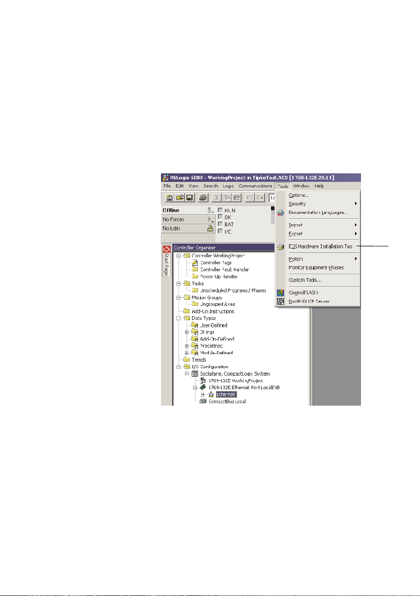
1. Start the program RSLogix.
2. Launch the EDS wizard by selecting “EDS Hardware Installation Tool” from the “Tools” menu.
1
1 Menu command “EDS Hardware Installation Tool”
Fig. 3/1: Launching the EDS wizard
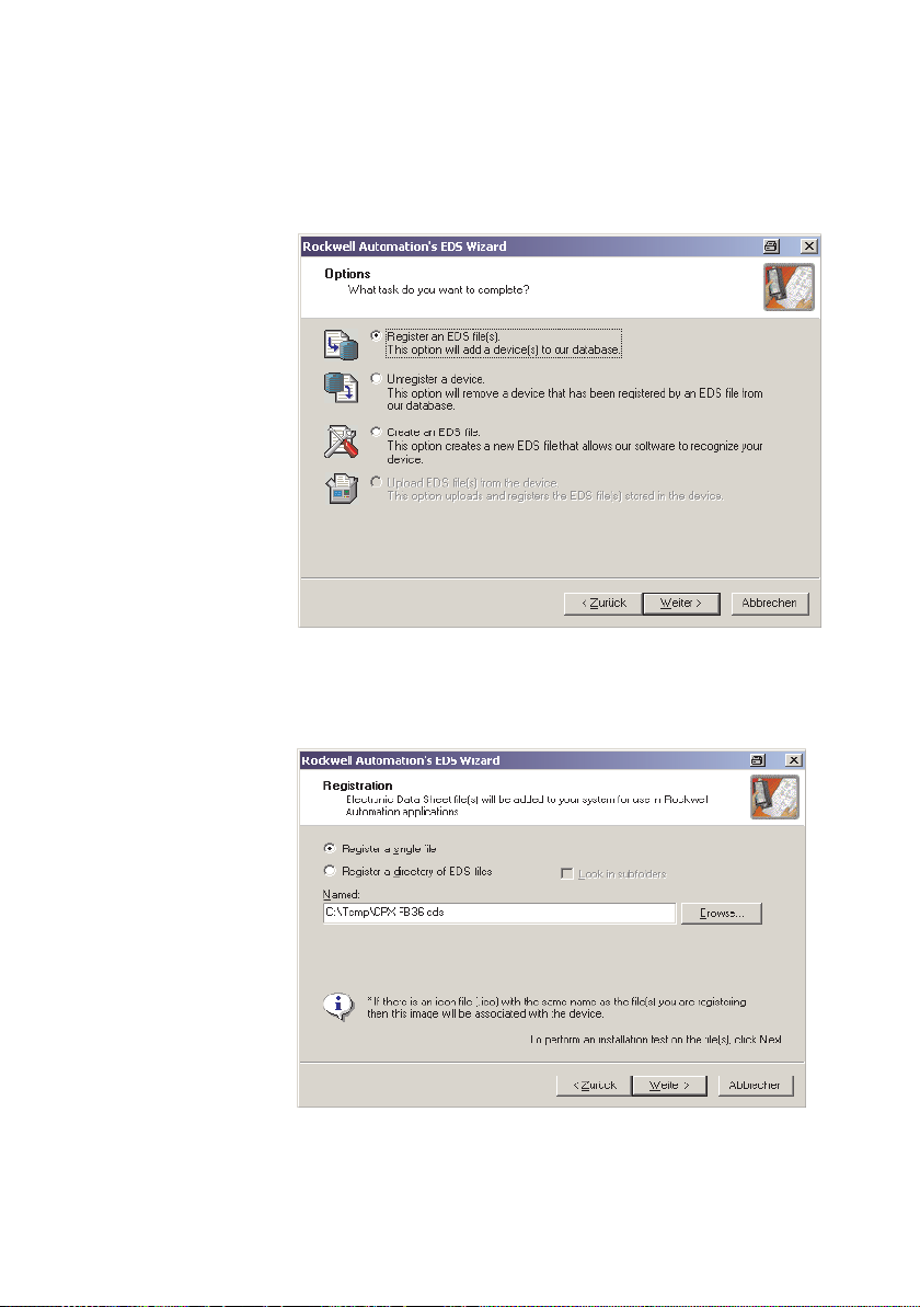
3. Select the option “Register an EDS-file(s)”.
Festo P.BE-CPX-F B36-EN en 1309NH English
3-5
Page 64
3. Commissioning
Fig. 3/2: EDS wizard - Options
3-6
4. Click the “Next >” button.
Fig. 3/3: EDS wizard with selected EDS file
Festo P.BE-CPX -FB36-EN en 1309NH English
Page 65
3. Commissioning
5. Select one of the following options:
– Register a single file
– Register a directory of EDS files
6. Click “Browse” to select the directory and name of the
EDS file.
7. Click the “Next >” button.
The procedure for registering the bus node in “RSLogix” is
complete.
Integrating participants in a project
The integration of the bus node in a new RSLogix project can
only be implemented if there is no online connection between
RSLogix and the controller ( “Communications” “Go
offline”).
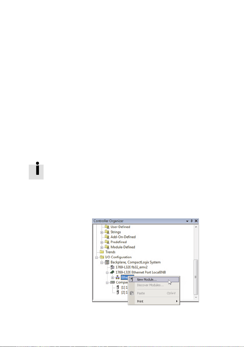
1. In the “Controller Organizer” window of the “RSLogix
Fig. 3/4: Context menu in the “Controller Organizer”
Festo P.BE-CPX-F B36-EN en 1309NH English
5000” program, right-click on “Ethernet” under the “I/O
Configuration” branch.
window
3-7
Page 66
3. Commissioning
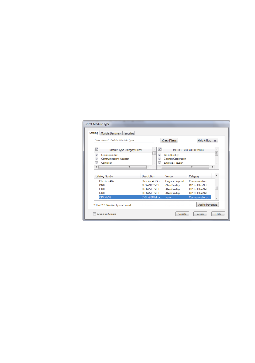
2. Select the command “New Module...” from the context
menu.
This opens the dialogue window “Select Module Type”.
3. Select the “Catalog” tab and choose the module with the
description “CPX-FB36 Ethernet Module” from the bottom
table.
3-8
Fig. 3/5: Integrating bus node CPX-FB36
4. Confirm your selection by pressing “Create”.
Configuring a participant
1. In the “Controller Organizer” window right-click on the
newly integrated module and select the “Properties” command in the context menu.
This opens the dialogue window “Module Properties”.
2. Check and alter the IP address if necessary.
3. Click the “Change” button.
This opens the dialogue window “Module Definition”.
Festo P.BE-CPX -FB36-EN en 1309NH English
Page 67
3. Commissioning
4. Enter the correct length of the CPX I/O data in the “Size”
field.
This value can either be calculated or retrieved using
CPX-FMT or a web server.
The basic configuration of the CPX terminal in the project is
now complete.
• Parameterise the modules and valve terminals used in the
CPX terminal ( chapter 3.2).
Festo P.BE-CPX-F B36-EN en 1309NH English
3-9
Page 68
3. Commissioning
3.1.2 Configuration with Generic Ethernet Module
This section describes the manual configuration process of a
participant via the “RSLogix” program using a “Generic Ethernet Module”.
Integrating participants in a project
The integration of the bus node in a new RSLogix project can
only be implemented if there is no online connection between
RSLogix and the controller ( “Communications” “Go
offline”).
1. In the “Controller Organizer” window of the “RSLogix”
program, right-click on “Ethernet” under the “I/O Configuration” branch ( Fig. 3/4).
2. Select the option “New Module” from the context menu.
3-10
This opens the dialogue window “Select Module Type”.
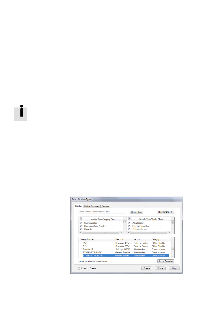
3. Select the “Catalog” tab and choose the module with the
description “Generic Ethernet Module” from the bottom
table.
Fig. 3/6: Integrating a bus node as a Generic Ethernet
Module
Festo P.BE-CPX -FB36-EN en 1309NH English
Page 69
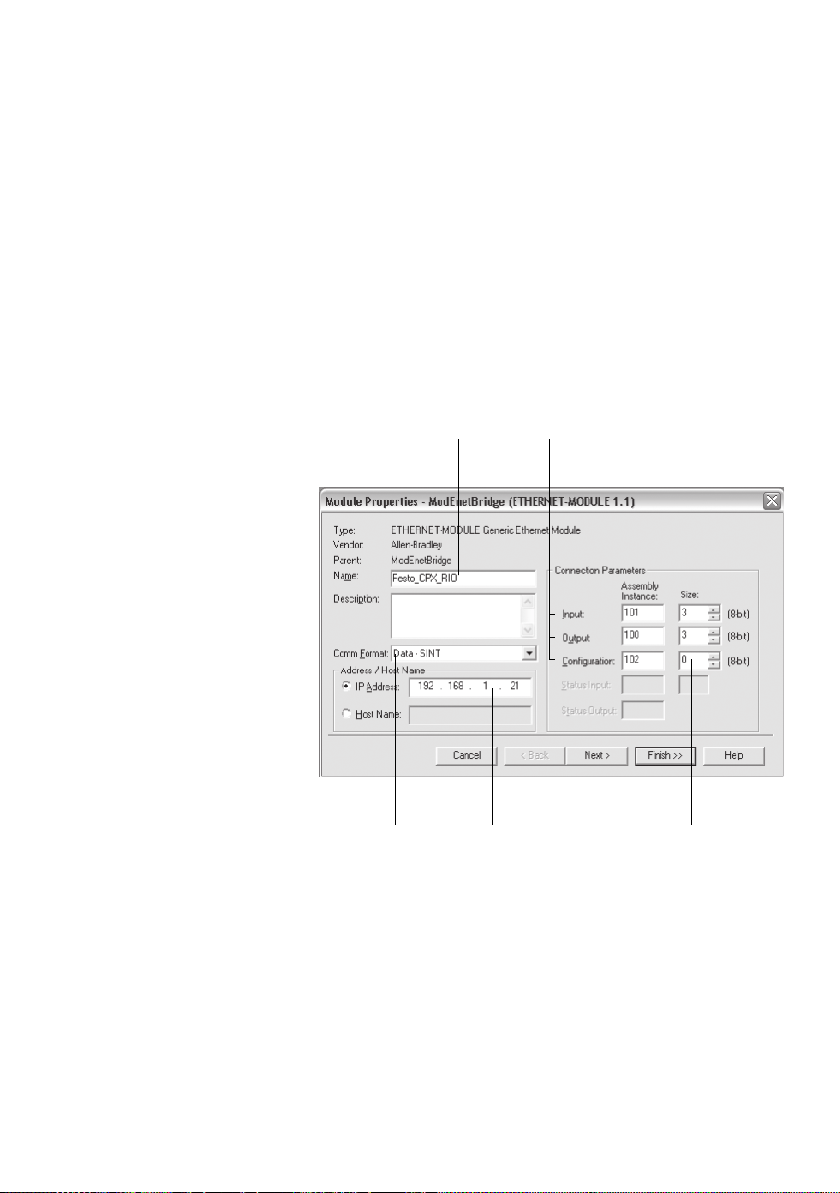
3. Commissioning
1 Name
(freely selectable)
2 Connection
parameters of the
Assembly
lnstances
4. Confirm your selection by pressing “Create”.
Configuring a participant
1. In the “Controller Organizer” window right-click on the
newly integrated module and select the “Properties” command in the context menu.
This opens the dialogue window “Module Properties”.
12
3 Size of the
Assembly
Instances
4 IP address
5 Data format
Fig. 3/7: “Module Properties” dialogue window
2. Enter a name for the bus node 1.
3. Select one of the following data formats from the list field
“Comm F ormat” 5:
–DATA-SINT
–DATA-INT
Festo P.BE-CPX-F B36-EN en 1309NH English
345
3-11
Page 70
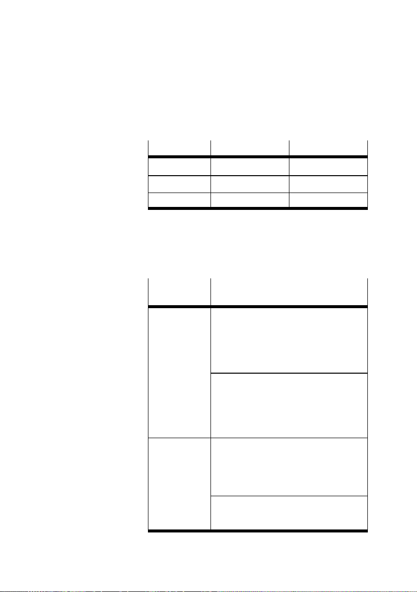
3. Commissioning
4. Enter the following values in the “Assembly Instance”
fields 2 depending on the data format.
Data format
Input 101 111
Output 100 110
Configuration 102 102
DATA - SINT DATA - INT
Tab . 3/3: Input values for “Assembly Instance”
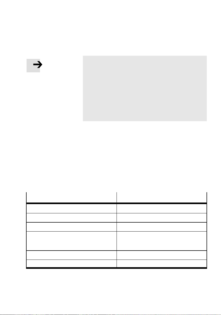
5. Enter the following values in the “Size” fields 3 depend-
ing on the operating mode.
Operating
Values
mode
Remote I/O For “Input” and “Output” the number of
allocated inputs/outputs of the CPX
terminal:
– for data format SINT: in bytes
– for data format INT: in words
( Appendix Tab. B/9)
For “Configuration”:
– the number of memory slots occupied by
CPX parameters
or
– 0 (standard setting)
Configuration Assembly not used
3-12
Remote
Controller
For “Input” and “Output” the number of
inputs and outputs set on the CPX-FB36:
– for data format SINT: in bytes
– for data format INT: in words
( chapter 1.2.3, Tab. 1/3)
For “Configuration”:
– 0 (standard setting)
Configuration Assembly not used
Tab. 3/4: Input values for “Size”
Festo P.BE-CPX -FB36-EN en 1309NH English
Page 71
3. Commissioning
Note for Remote I/O operating mode
The “RSLogix” program does not allow the input “0” as a
data length (size) for inputs and outputs.
When using a CPX terminal that does not have any inputs:
• Activate the status bits with the help of DIL switch
group 2 ( Tab. 1/2)
The following settings then apply for the input data:
–forSINTformat: Size=2
– for INT format: Size = 1
6. Enter an “IP address” 4.
7. Confirm all entries by selecting “Apply”.
8. Close the “Module Properties” dialogue window by pressing “OK”.
Using participant properties
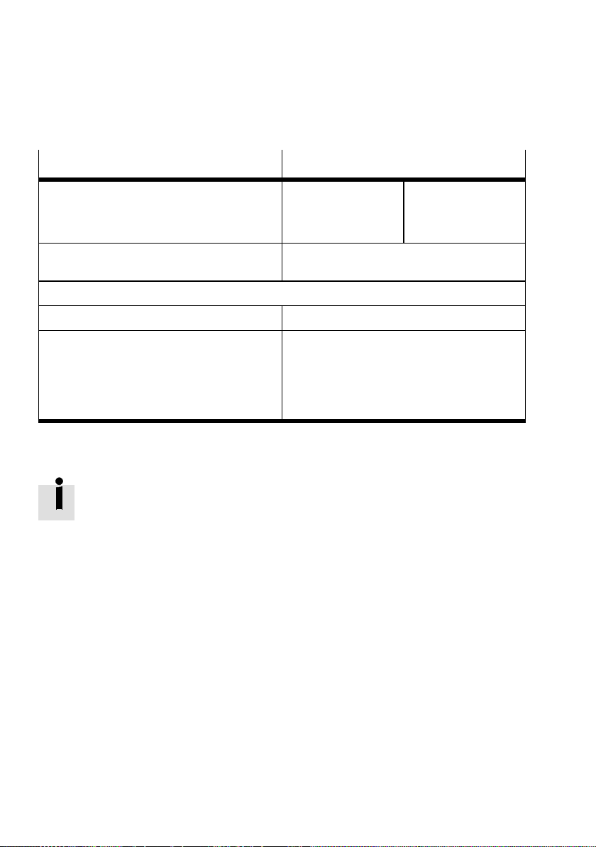
• Use the following data in your controller.
Benefit
Vendor name Festo Corporation
Vendor ID 26 = 1A
Device Type 12 = 0C
Product code (depends on operating mode)
– Remote I/O
– Remote Controller
Major Revision 1
Input size / output size Depends on CPX equipment
Tab. 3/5: Participant properties - Part 1
Festo P.BE-CPX-F B36-EN en 1309NH English
Description
h
h
14026 = 36CA
14027 = 36CB
h
h
3-13
Page 72
3. Commissioning
Benefit Description
Assembly Instances
– Input
– Output
– Configuration
Product name CPX-FB36 Remote I/O
Advanced EtherNet/IP participant properties
Request Packet Interval (RPI) ≥1ms
Connections:
– Total of all connections
–ExclusiveOwner
– Input only
–Listenonly
SINT format
101
100
102
CPX-FB36 Remote Controller
Max. 32
Max. 1
Max. 32
Max. 31 (there has to be simultaneously at least
1 Excl.Owner or an input only connection)
Tab. 3/6: Participant properties - Part 2
This basic configuration of the CPX terminal in the network is
now complete.
Information about parameterisation of the modules and valve
terminals used in the CPX terminal can be found in
chapter 3.2.
INT format
111
110
102
3-14
Festo P.BE-CPX -FB36-EN en 1309NH English
Page 73
3. Commissioning
3.1.3 Configuration with CPX-FMT
With the help of the CPX F esto Maintenance Tool (CPX-FMT) it
is possible to export the configuration and complete parameterisation of a CPX terminal to a file.
ThisfilecanthenbeimportedasanRSLogixproject.
Exporting a configuration from CPX-FMT
The CPX-FMT software is available online
www.festo.com/sp/cpx Engineering Software.
1. Start the “CPX-FMT” program.
2. Make sure there is an Ethernet connection between the
CPX-FMT and the CPX terminal.
3. Activate the online function to transfer the current configuration of the bus node to the PC.
4. Change the configuration and parameterisation for the
If you do not want to use this online function, you can also
configure the CPX terminal offline.
Modifications are also possible after importing the project to
the “RSLogix” program.
Festo P.BE-CPX-F B36-EN en 1309NH English
CPX terminal if necessary with CPX-FB36.
3-15
Page 74
3. Commissioning
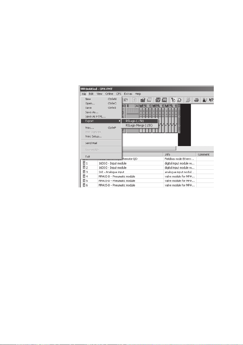
5. Open the dialogue window for exporting the configuration
by selecting “File” > “Export” > “RSLogix (.L5K)” (File > Export > RSLogix (.L5K)).
3-16
Fig. 3/8: Exporting the configuration for “RSLogix”
6. Select a directory and a name to save the L5K file.
Importing the configuration to “RSLogix”
1. Start the program “RSLogix”.
2. Click “Open” in the “File” menu and select the saved L5K
file.
3. Click “Open”.
4. Select the directory and name of the file to be imported.
5. Click “Import”.
The CPX-FMT file is imported into a new RSLogix project
(.ACD) as an Ethernet module.
Festo P.BE-CPX -FB36-EN en 1309NH English
Page 75
3. Commissioning
Integrating the CPX terminal into an existing
RSLogix project
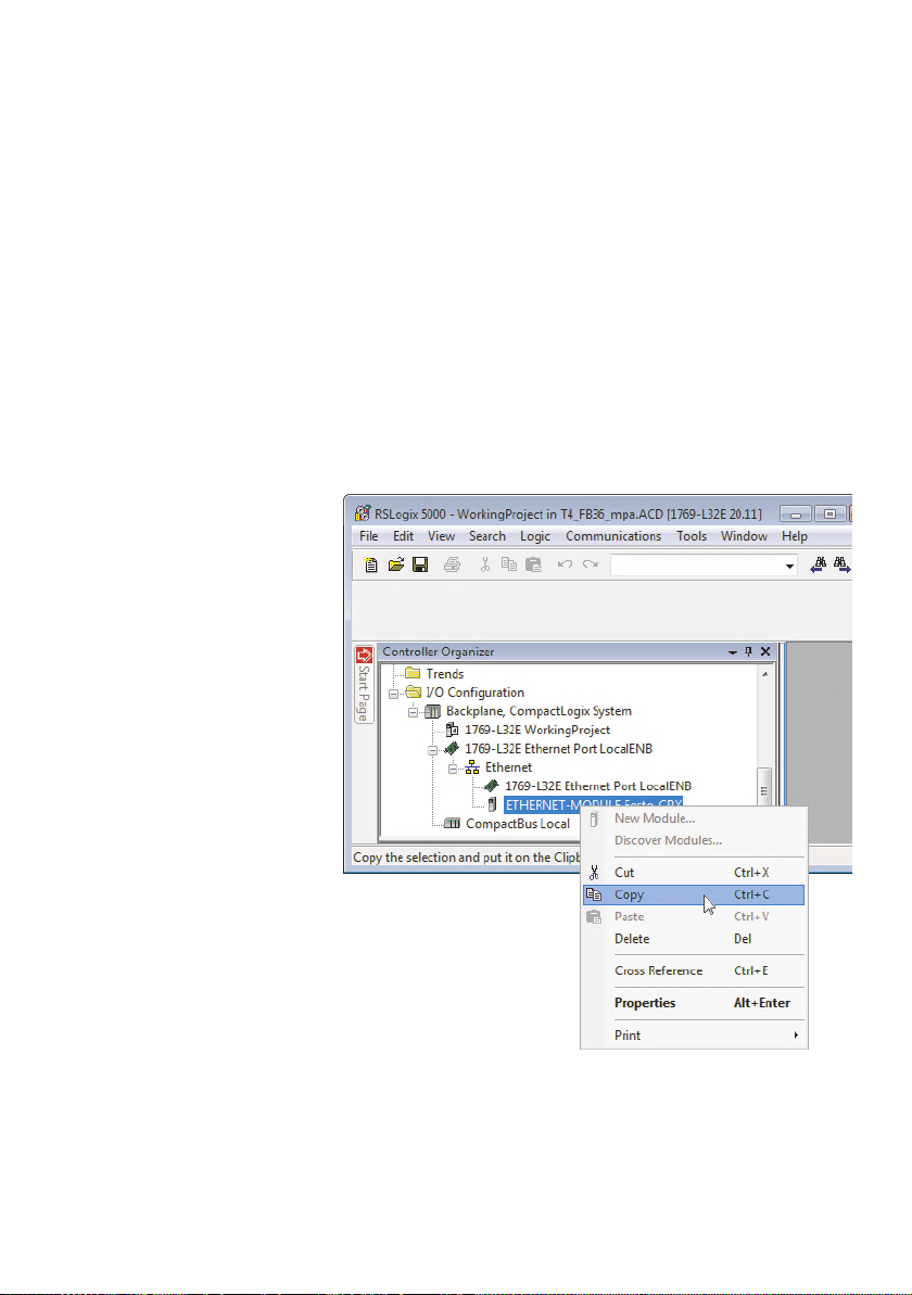
The CPX terminal which is configured and parameterised under CPX-FMT appears in the “RSLogix 5000” program as a
new Ethernet module.
To integrate this module into an existing RSLogix project:
1. Right-click on the Ethernet module and select the “Copy”
command from the context menu.
Fig. 3/9: Copy the Ethernet module
Festo P.BE-CPX-F B36-EN en 1309NH English
3-17
Page 76
3. Commissioning
2. Open an RSLogix project to integrate the imported Ethernet module.
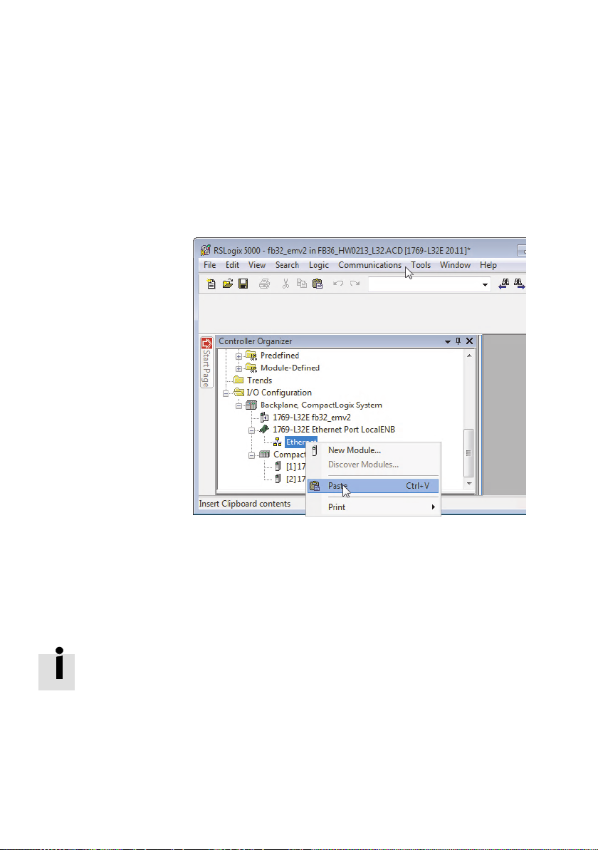
3. Right-clickon“Ethernet”intheexistingRSLogixproject
and select the “Paste” command from the context menu.
3-18
Fig. 3/10: Inserting an Ethernet module
All of the necessary settings of the CPX terminal are transferred to the RSLogix project. This includes, among other
things, I/O data lengths and IP configuration, as well as all
module and system parameters.
The basic configuration and parameterisation of the CPX terminal in the network is now complete.
To change the parameterisation of the modules and valve
terminals used in the CPX terminal, use the “RSLogix” program.
Festo P.BE-CPX -FB36-EN en 1309NH English
Page 77

3. Commissioning
3.1.4 Configuration in the Remote Controller operating mode
When using a CPX-FEC or CPX-CEC in your CPX terminal, the
CPX-FB36 is to be used as the Remote Controller.
In principle, the bus node is configured in the same manner
as in the Remote I/O operating mode, but with different I/O
data lengths.
The bus node then occupies 8 or 16 input bytes and 8 or 16
output bytes (dependent on the switch position DIL 2.2
Tab. 1/2).
These inputs and outputs are available to the control program of the CPX-FEC or CPX-CEC.
To use the Remote Controller operating mode:
1. Use DIL switch group 1 to set the bus node to the Remote
Controller operating mode and select an EtherNet/IP or
Modbus TCP protocol ( chapter 1.2.1).
2. Use DIL switch group 2 to set the required data field size
3. Follow the instructions in chapter 3.1.1 and 3.1.2 for com-
The bus node is thus configured as remote controller.
Festo P.BE-CPX-F B36-EN en 1309NH English
– DIL 1.1: ON
– DIL 1.2: OFF (EtherNet/IP protocol)
DIL 1.2: ON (Modbus TCP protocol)
( chapter 1.2.3).
missioning with the “RSLogix” program.
3-19
Page 78
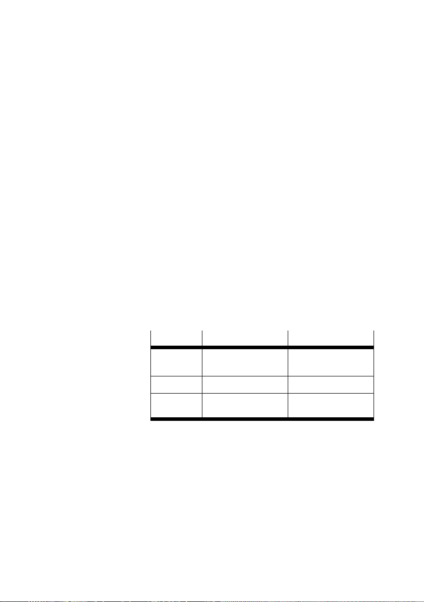
3. Commissioning
3.1.5 Setting up a listen-only connection
When the participant properties have been configured (e.g.
by installation of an EDS file), the following steps are required
for configuration.
1. Install your CPX terminal and set the network addressing
( chapter 1.3.4).
2. Establishaconnectiontothebusnode.Todothis,usethe
profile “GenericEthernet Device” in the “RSLogix” program ( chapter 3.1.2).
3. Open the “Module Properties” dialogue window.
4. Selectthedataformat“DATA-SINT”fromthe“Comm
Format” list field ( Fig. 3/7).
5. Enter the following values in the “Connection parameters”
field:
3-20
Benefit
Input 101 Number of inputs set
Output 1 0
Configuration
Assembly Instanc e Size
on the bus node
102 (Configuration
Assembly)
0
Tab . 3/7: Properties for “Connection parameters”
6. Enter the IP address of the bus node.
Festo P.BE-CPX -FB36-EN en 1309NH English
Page 79
3. Commissioning
3.2 Parameterisation
Warning
Uncontrolled movements of the actuators, undefined
switching states
Injury to people, damage to the machine and system
• During the parameterisation process make sure that
nobody is within the sphere of influence of moving parts
of your system.
Parameterisation of the CPX-FB36 influences the behaviour
of the CPX terminal.
The CPX terminal is supplied from the factory with preset
parameters. These parameters are saved in the bus node.
These parameters can be used to largely adapt the behaviour
of the CPX terminal to the relevant application.
A distinction is made between the following variants:
– System parameters, e.g. setting reaction times, switching
– Module parameters (module- and channel-specific), e. g.
– Parameters of the diagnostic memory
A detailed description of the individual parameters as well as
basic principles of application can be found in the CPX system
description ( P.BE-CPX-SYS-...).
The module parameters can be found in the descriptions for
the modules, e.g. description of the CPX pneumatic interfaces
and CPX I/O modules ( P.BE-CPX-EA-...).
Festo P.BE-CPX-F B36-EN en 1309NH English
off fault messages
diagnostic settings, settings for error handling, settings
for debounce times of inputs, settings for forcing
3-21
Page 80
3. Commissioning
3.2.1 Parameterisation when switching on (system start)
Parameterisation of the CPX terminal is initially dependent on
the setting of the “System start” parameter. This parameter
establishes whether the default parameters or the parameters saved by the user in the bus node are used wh en switching on the CPX terminal.
The parameterisation is loaded again after every interruption
of the power supply or the network connection. An exchange
of individual CPX modules is therefore possible, for example,
without the need for re-parameterisation.
Sequence of parameterisation when switching on
the CPX terminal
System start with default parameters
1. The controller transmits the parameterisation that is
saved in the controller to the bus node.
3-22
2. The bus node distributes this parameterisation to the
individual modules.
System start with saved parameters
1. The bus node distributes the parameterisation that is
saved in the bus node to the individual modules.
The parameterisation saved in the bus node can be overwritten accidentally by the controller.
• Prevent this by changing the “Configuration” connection
parameter using the “RSLogix” programme.
Festo P.BE-CPX -FB36-EN en 1309NH English
Page 81
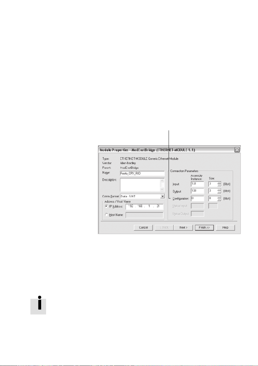
3. Commissioning
1 “Assembly-
lnstance” connection parameter
for “Configuration”
To change the “Configuration” connection parameter using
the “RSLogix” programme, proceed as follows:
1. Make sure there is no online connection between RSLogix
and the controller ( “Communications” “Go offline”).
2. Double-click the “Ethernet” branch in the “Controller Organizer” window to open the “Module Properties” dialogue window .
1
Fig. 3/11: “Module Properties” dialogue window
3. Enter the value “0” for “Configuration” under the As-
4. Close the “Module Properties” dialogue window by press-
The setting “System start with saved parameters” is indicated
by the permanent illumination of the M-L ED on the bus node
after the system has started.
Festo P.BE-CPX-F B36-EN en 1309NH English
sembly Instance “Connection Parameters” field.
ing “Finish >>”.
3-23
Page 82

3. Commissioning
Replacing the bus node
When replacing a bus node with the setting “System start
with saved parameters”, the CPX terminal is not parameterised automatically by the higher-order controller.
1. Before replacing the bus node save the parameterisation
of the CPX terminal in a CPX-FMT file.
2. After replacing the bus node transfer the parameterisation to the new bus node. Use the command “Load settings...” in the CPX menu.
3. Enable all settings in the “Load” window and start the
transfer to the bus node by pressing “OK”.
3-24
Festo P.BE-CPX -FB36-EN en 1309NH English
Page 83

3. Commissioning
3.2.2 Methods of parameterisation
Method Description Benefits Disadvantages
Parameterisation via
configuration data
(ConfigurationAssembly)
section 3.2.3
Parameterisation with the
operator unit CPX-MMI
section 3.2.4
Parameterisation in the
PLC user program
section 3.2.5
Parameterisation using
CPX-FMT and system start
with saved parameters
section 3.2.6
1) It is possible to copy the c urrent parameterisationwith the help of the CPX-MMI operator unit.
Export
parameterisation of
the CPX terminal by
using CPX-FMT.
Import the settings in
the programme
“RSLogix”.
Parameterisation is
carried out with
entries via the menus.
Parameterisation
through explicit
messaging;
parameters are saved
in the PLC.
Parameterisation is
carried out with
entries via the menus.
Parameters are saved
directly in the
CPX-FB36.
Start with saved
parameters necessary.
– Convenient transfer
of the complete
configuration for a
CPX terminal.
–Convenient
parameterisation
via menu
navigation (plain
text).
– Parameters are
reloaded after
every restart and
are therefore also
retained if the
device is replaced.
–Fast,simple
parameterisation
during
commissioning for
testing the
parameters.
– Parameterisation of
the CPX terminal is
saved locally in the
bus node and is lost
when replaced.
– Requirement: User
program required.
– Parameterisation of
the CPX terminal is
saved locally in the
bus node and is lost
when replaced.
1)
1)
Tab . 3/8: Methods of parameterisation
Further information about parameterisation can be found in
the CPX system description (P.BE-CPX-SYS...).
Festo P.BE-CPX-F B36-EN en 1309NH English
3-25
Page 84
3. Commissioning
Note
The last parameterisation transferred in the CPX terminal is
always valid.
3.2.3 Parameterisation via configuration data
Parameterisation via configuration data (Configuration Assembly) corresponds to the method for configuration with
CPX-FMT and transfer of all parameters to the “RSLo gix” program ( section 3.1.3).
3.2.4 Parameterisation with the operator unit CPX-MMI
The operator unit CPX-MMI offers menu-driven access to the
parameterisation. It does not require any additional configuration software.
Information about using the operator unit can be found in the
corresponding description.
3.2.5 Parameterisation in the PLC user program
Program-controlled access to parameters is effected via “Explicit Messaging”. The addresses of the EtherNet/IP object
model that are required for this can be found in Appendix C.1.
Further information on programming this data transmission
can be found in the manual for your controller .
3-26
Festo P.BE-CPX -FB36-EN en 1309NH English
Page 85

3. Commissioning
3.2.6 Parameterisation using CPX-FMT and system start with saved parameters
Parameterisation corresponds to the method for configuration with CPX-FMT and transfer of all parameters to the
“RSLogix” program ( section 3.1.3).
The parameterisation of the CPX terminal is saved directly in
the CPX-FB36. To use this parameterisation the “System
start” parameter needs to be set to “Saved parameters”
( section 3.2.1).
Festo P.BE-CPX-F B36-EN en 1309NH English
3-27
Page 86
3. Commissioning
3.3 Reaction of the outputs in the Fail safe or Idle mode
Idle mode is assumed by the participants after a request by
the master.
The error status (Fail safe mode, also referred to as Fault
mode) defines the status the relevant channel is to assume in
the event of fieldbus communication faults.
In this status, the following applies:
– Inputs are transmitted
– Output channels of the participants are no longer up-
dated
In the Fail safe or Idle mode, outputs can assume one of the
following states:
3-28
Digital outputs/valves
Freeze current status Freeze current status
Reset output Desired analogue value
Set output
Analogue outputs
Tab. 3/9: Possible states in the Fail safe/Idle mode
You can determine the status to be assumed for each output
channel (output or solenoid coil) separately. The standard
setting is “Reset of the output channel”.
Further information can be found in the CPX system description ( P.BE-CPX-SYS-...).
Festo P.BE-CPX -FB36-EN en 1309NH English
Page 87
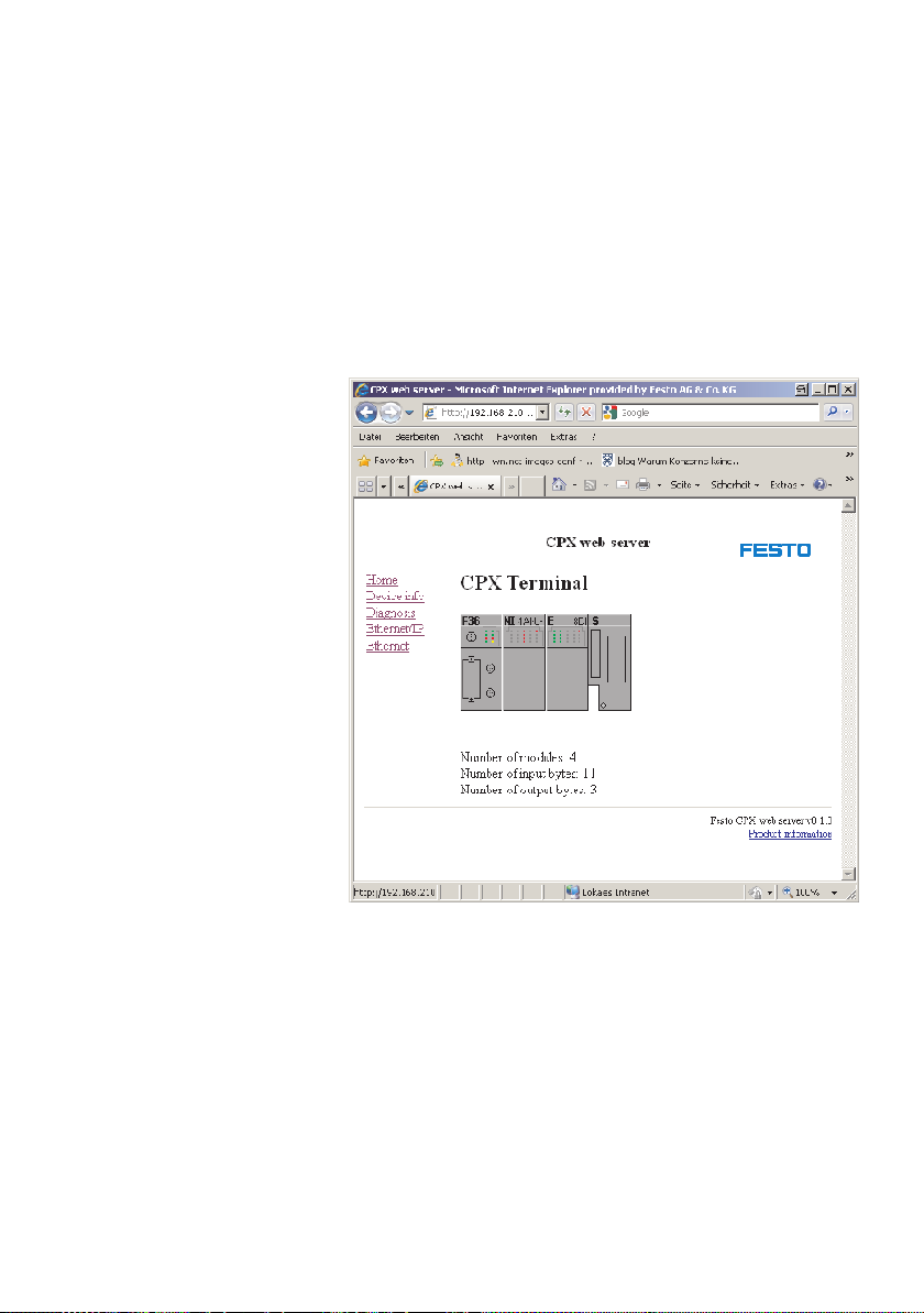
3. Commissioning
3.4 Web server
A web server is integrated in the bus node CPX-FB36. The
web server makes available the most important parameters
and diagnostic functions.
Fig. 3/12: Web server of the CPX-FB36
Procedure
1. Open an Internet browser of your choice on a PC that is
2. In the address bar of the Internet browser enter the IP
Festo P.BE-CPX-F B36-EN en 1309NH English
connected to the network.
address of the bus node as follows:
http://192.168.2.xxx
3-29
Page 88

3. Commissioning
3.5 Checklist for commissioning a CPX terminal
• Please observe the general commissioning instructions in
the CPX system description.
• Check the DIL switch settings and the network configura-
tion before using and replacing CPX terminals.
• Check the configured address range. If necessary, test the
I/Os.
• ChecktheaddressassignmentoftheI/OsontheCPX
terminal. For this purpose you can, if necessary, force the
I/Os ( CPX system description).
• Make sure that the desired parameterisation of the CPX
terminal in the start-up phase or after network interruptions is restored by the interface module.
This ensures that if the CPX terminal is replaced, the new
terminal will also be operated with the desired parameter
settings.
3-30
• Use spot checks if necessary to check the parameterisa-
tion, either with a configuration program (e.g. RSLogix) or
with an operator unit (e.g.B. CPX-MMI).
Festo P.BE-CPX -FB36-EN en 1309NH English
Page 89

Diagnostics
Chapter 4
Diagnostics
4-1Festo P.BE-CPX-FB36-E N en 1309NH E nglish
Page 90

4. Diagnostics
Ta b l e o f co n te n t s
4. Diagnostics 4-1...................................................
4.1 Summary of diagnostics options 4-3...................................
4.2 Diagnostics via LEDs 4-4............................................
4.2.1 CPX-specific LEDs 4-6.......................................
4.2.2 Network-specific LEDs 4-9....................................
4.2.3 Protocol-specific LEDs 4-10....................................
4.3 Diagnostics via status bits 4-12........................................
4.4 Diagnostics via I/O diagnostic interface 4-13.............................
4.5 Diagnostics via EtherNet/IP 4-15.......................................
4.6 Diagnostics via Modbus TCP 4-16......................................
4.7 Error handling 4-17..................................................
4-2
Festo P.BE-CPX -FB36-EN en 1309NH English
Page 91
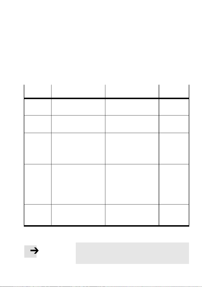
4. Diagnostics
4.1 Summary of diagnostics options
The CPX terminal provides comprehensive and user-friendly
options for diagnostics and error handling. The following options
are available, depending on the configuration:
Diagnostics
Brief description Benefits Detailed de-
option
LED display The LEDs show directly
Status bits Internal inputs that supply
I/O
diagnostics
interface
Diagnostics via
EtherNet/IP
Diagnostics via
the oper ator
unit
configuration errors, hardware
errors, bus errors, etc.
coded common diagnostic
messages.
The I/O diagnostic interface is
a bus-independent diagnostic
interface at I/O level which
permits access to internal data
of the CPX terminal (16 inputs
and 16 outputs).
Access to all system data of
the CPX terminal via the
fieldbus.
Operator unit CPX-MMI for
convenient and menu-driven
display of diagnostic
information.
scription
Fast “On-the-spot” recognition
of errors
Fast access to error messages,
irrespective of the module and
master.
Detailed error detection
irrespective of the fieldbus
used.
Detailed module-related and
channel-related error detection
as well as ac c ess to the
diagnostic memory in the
online mode of the
programming/configuration
software and in the PLC user
program.
Fast “On-site” error detection Operator unit
Section 4.2
Section 4.3 and
CPX system
description
Section 4.4 and
CPX system
description
Appendix B
(EtherNet/IP
Objects)
description
Tab . 4/1: Diagnostics options
Note
Observe that the diagnostic information displayed depends on the parameterisation of the CPX terminal.
Festo P.BE-CPX-F B36-EN en 1309NH English
4-3
Page 92
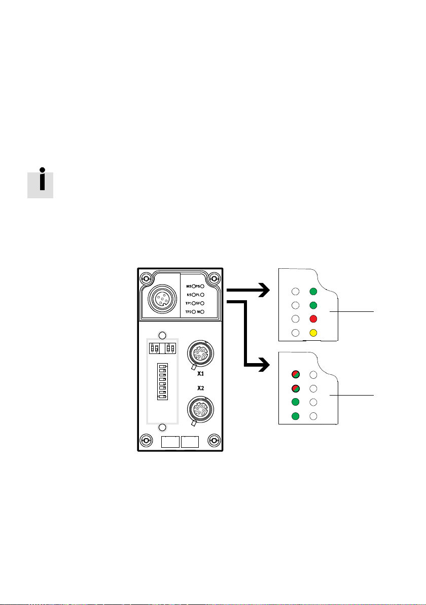
4. Diagnostics
4.2 Diagnostics via LEDs
LEDs for the diagnostics of the CPX terminal are available on
the bus node as well as on the individual modules.
The meaning of the LEDs on the electric modules can be
found in the description for the relevant module.
LEDs at the bus node CPX-FB36
The LEDs on the cover indicate the operating status of the
CPX bus node.
1 CPX-specific LEDs
PS: Power system
PL: Power Load
SF: System Failure
M: Modifiy
MS
NS
TP1
TP2
PS
PL
SF
M
1
2 Bus status LEDs
MS: Module Status
NS: Network Status
TPx:Link/Traffic 1/2
Fig. 4/1: LEDs on the CPX bus node
4-4
PS
MS
PL
NS
SF
TP1
TP2
M
Festo P.BE-CPX -FB36-EN en 1309NH English
2
Page 93
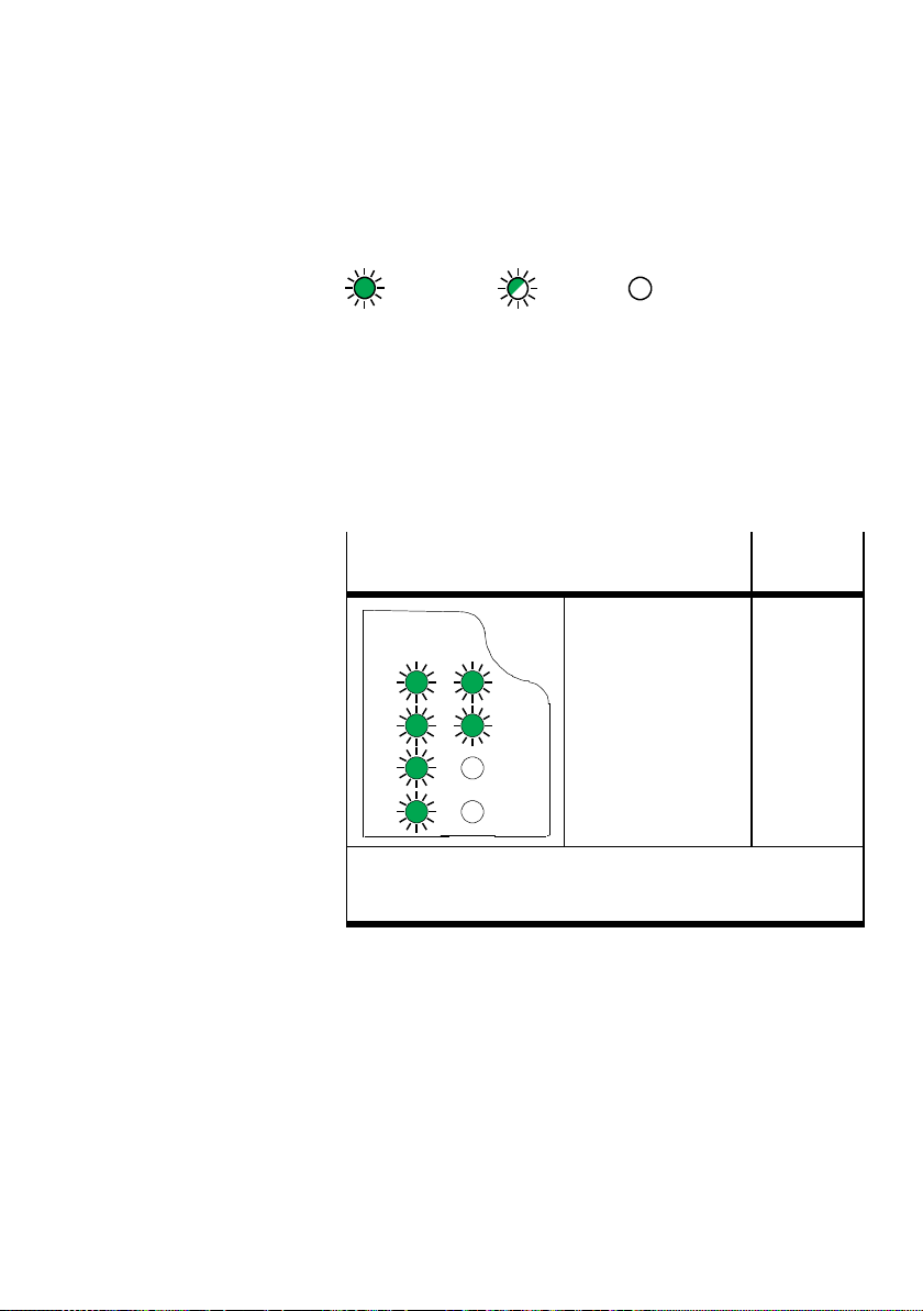
4. Diagnostics
TheLEDsareshownintheirvariousstatesasfollows:
lit; flashing; off;
Normal operating status
In normal operating status the following L EDs illuminate
green. The SF LED does not illuminate. The M-LED only illuminates with the setting “System start with stored parameterisation and stored CPX expansion” ( function number 4402).
LED display
The following LEDs illuminate green:
–PS
PS
MS
NS
TP1
TP2
1) Steady light: Ready for data transmission
Flashing: Data transmission ongoing
2) Only illuminates when starting with saved parameters
PL
SF
M
–PL
–MS
–NS
– TP1/2
The SF LED does not illuminate:
–SF
M-LED
1)
2)
Tab. 4/2: Normal operating status
Operating
status
Standard
Festo P.BE-CPX-F B36-EN en 1309NH English
4-5
Page 94
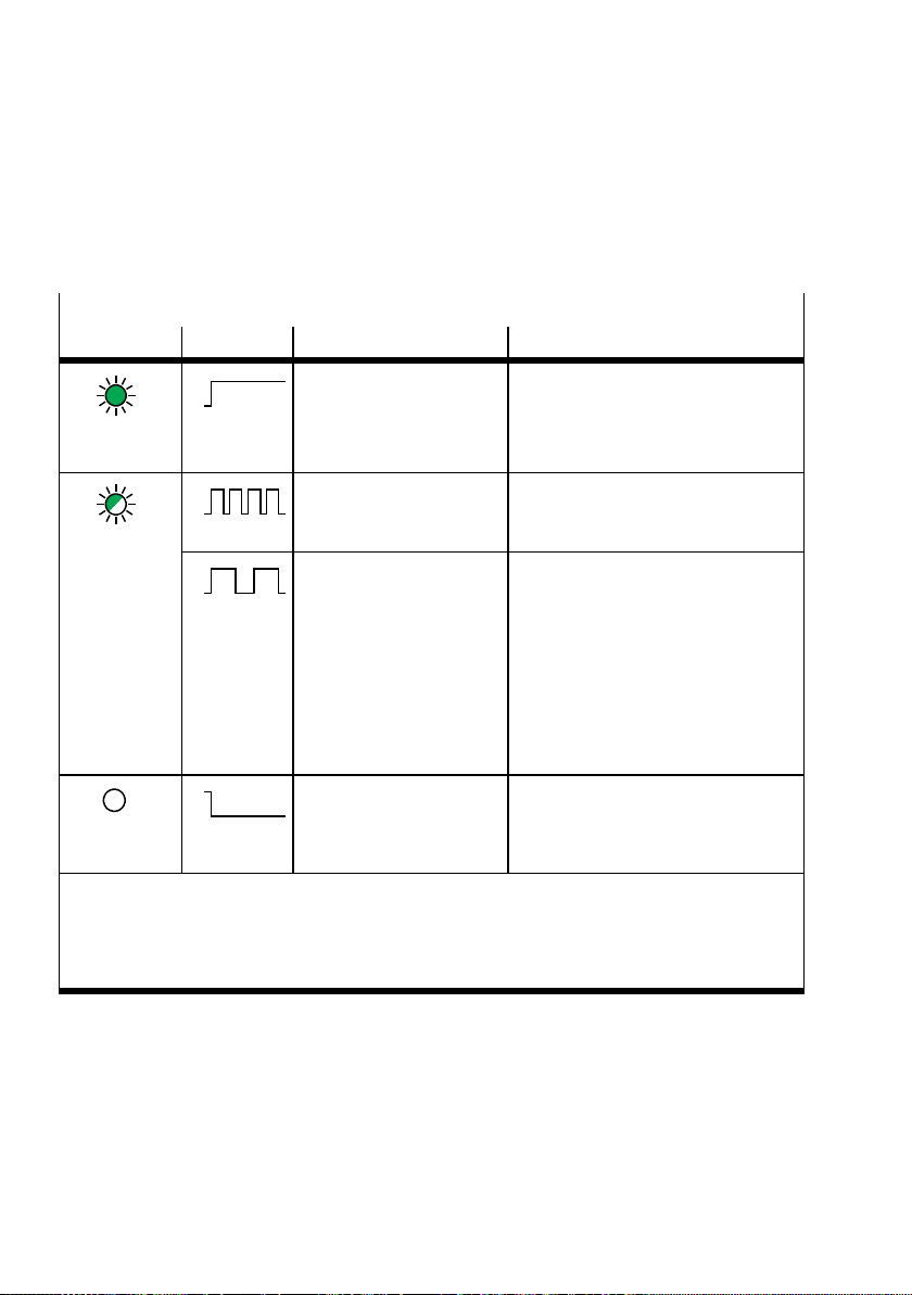
4. Diagnostics
4.2.1 CPX-specific LEDs
PS (power system) – power sensor/logic supply
LED (green) Sequence Status Significance/error handling
ON
OFF
LED
No error. Operating
voltage/sensor supply
applied
–
illuminated
ON
OFF
LED flashes
ON
OFF
Operating voltage/sensor
supply outside the
tolerance range
Internal fuse for the
operating voltage/sensor
supply has responded
Eliminate undervoltage
1. Eliminate short circuit/overload on
module side.
2. Dependent on the parameterisation
of the mo dule (module
parameter)
• The sensor supply voltage will be
1)
:
switched on again automatically
after the short circuit has been
eliminated (factory setting)
• Power Off/On is necessary
ON
OFF
Operating voltage/sensor
supply is not applied
1)
Check the operating voltage
connection of the electronics
LED not
illuminated
1) The short-circuit, overload and undervoltage diagnostic messages (SCS/SCO/SCV, U
the complete CPX terminal can be suppressed using the “Monitoring” system parameter (function
OUT/VAL
no. 4401).
Monitoring that is set separatelyfor each module ( parameter “Monitoring CPX module”) is not
affected by this system parameter.
)for
Tab. 4/3: LED display PS (Power System)
4-6
Festo P.BE-CPX -FB36-EN en 1309NH English
Page 95
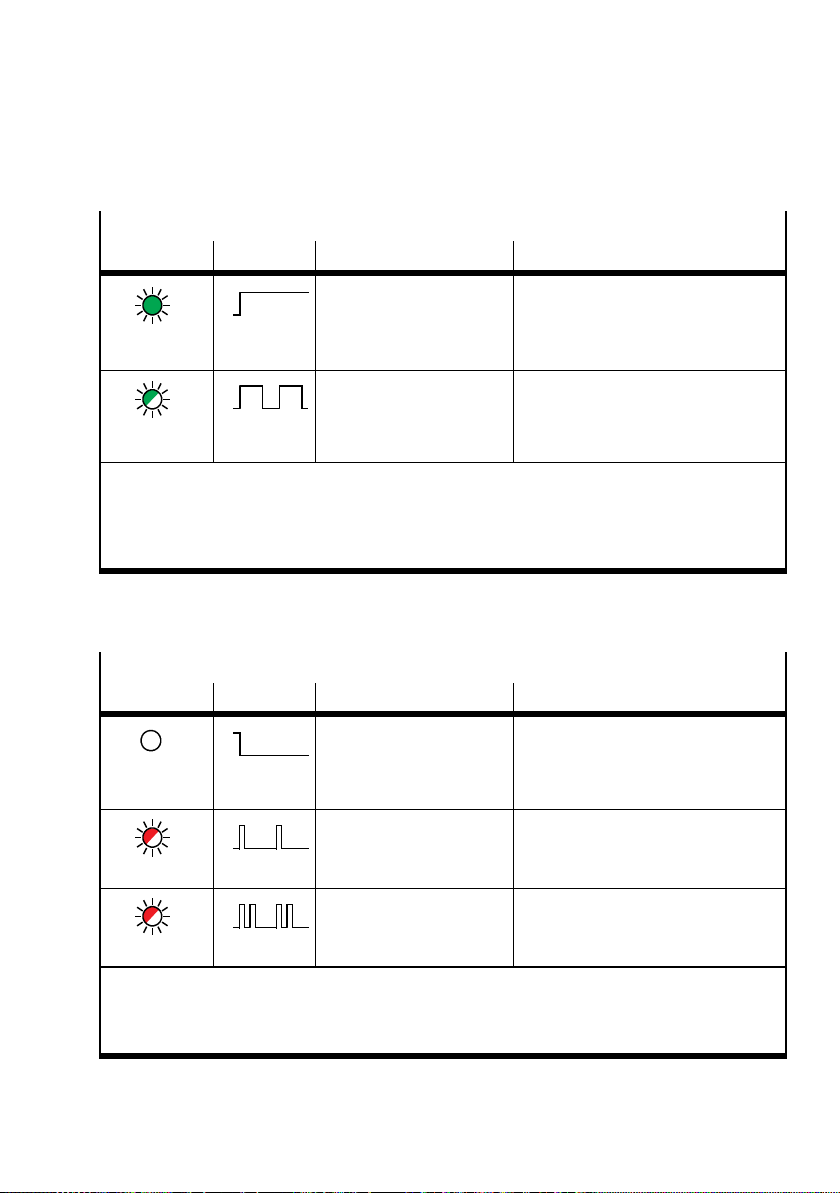
4. Diagnostics
PL (power load) – power load supply (outputs/valves)
LED (green) Sequence Status Significance/error handling
ON
OFF
No error. Load voltage
applied
None
LED
illuminated
ON
OFF
LED flashes
1) The short-circuit, overload and undervoltage diagnostic messages (SCS/SCO/SCV, U
the complete CPX terminal can be suppressed using the “Monitoring” system parameter (function
Load voltage at the system
supply or additional power
supply outside the
tolerance range
1)
Eliminate undervoltage
OUT/VAL
no. 4401).
Monitoring that is set separatelyfor each module ( parameter “Monitoring CPX module”) is not
affected by this system parameter.
Tab . 4/4: LED display PL (Power load voltage)
SF (system failure) – system fault
LED (red) Sequence1)Status Significance/error handling
ON
OFF
LED not
illuminated
ON
OFF
LED flashes
No error. –
Simple error/information
(error class 1)
Description of error numbers in the
CPX system description
)for
ON
OFF
Error
(error class 2)
Description of error numbers in the
CPX system description
LED flashes
1) The System Failure LED flashes dependent on the applicable error class.
Error class 1 (minor error): 1 * flash, pause time
Error class 2 (error): 2 * flashes, pause time
Error class 3 (severe error): 3 * flashes, pause time
Tab. 4/5: LED display SF (system error) - Part 1
Festo P.BE-CPX-F B36-EN en 1309NH English
4-7
Page 96
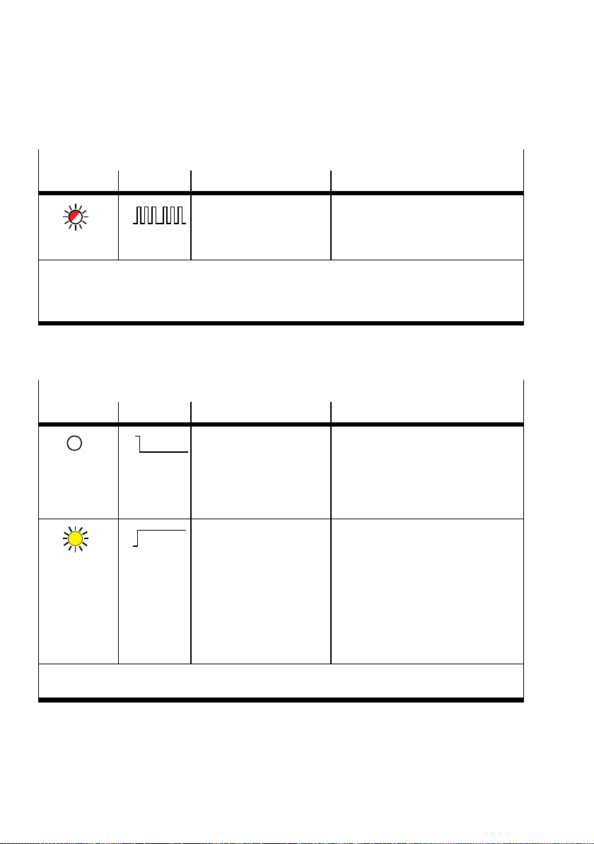
4. Diagnostics
SF (system failure) – system fault
LED (red) Sequence1)Status Significance/error handling
ON
OFF
Severe error
(error class 3)
Description of error numbers in the
CPX system description
LED flashes
1) The System Failure LED flashes dependent on the applicable error class.
Error class 1 (minor error): 1 * flash, pause time
Error class 2 (error): 2 * flashes, pause time
Error class 3 (severe error): 3 * flashes, pause time
Tab. 4/6: LED display SF (system error) - Part 2
M (modify) – parameterisation modified or forcing active
LED (yellow) Sequence Status Significance/error handling
ON
OFF
LED not
illuminated
ON
OFF
LED
illuminated
System start with standard
parametrisation (factory
setting) and current CPX
expansion set; external
parameterisation is
possible (presetting)
System start with saved
parametrisation and saved
CPX expansion has been
set;
Parameters and CPX
expansion are saved
remanently; external
parameterisation is
1)
blocked
None
CautionwhenreplacingCPXvalve
terminals with saved parametrisation.
With these CPX valve terminals,
parametrisation is not carried out
automatically by the higher-order
PLC/IPC when the terminal is
replaced. In these c ases, check which
settings are required before the
replacement and make these settings
if necessary.
1) The display of the Force function (LED flashing) has precedence over the displayof the setting for
system start (LED illuminated).
Tab. 4/7: LED display M (Modify) - Part 1
4-8
Festo P.BE-CPX -FB36-EN en 1309NH English
Page 97
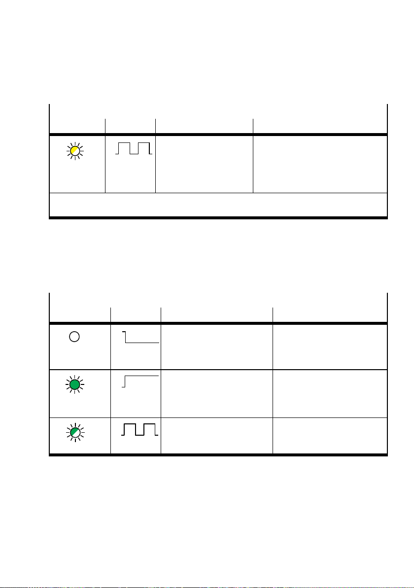
4. Diagnostics
M (modify) – parameterisation modified or forcing active
LED (yellow) Sequence Status Significance/error handling
1)
– The force function is enabled
(
system parameter force mode;
function no. 4402).
– Restar t CPX-FB36 (Power OFF/ON),
(
section 1.3.4)
LED flashes
ON
OFF
– Force is active
– Network settings have
been modified
1) The display of the Force function (LED flashing) has precedence over the displayof the setting for
system start (LED illuminated).
Tab. 4/8: LED display M (Modify) - Part 2
4.2.2 Network-specific LEDs
Connection/data traffic (Link/Traffic)
LED TP1/2 Sequence Status Error handling
ON
OFF
Does not
illuminate
ON
OFF
Illuminates
green
ON
OFF
Flashes green
No network connection /
network cable not connected
Network connection OK (Link) –
Data traffic (traffic)
Flashing frequency is
dependent on the traffic.
• Check networkconnection
–
Tab. 4/9: LED display TPx (Link/Traffic)
Festo P.BE-CPX-F B36-EN en 1309NH English
4-9
Page 98
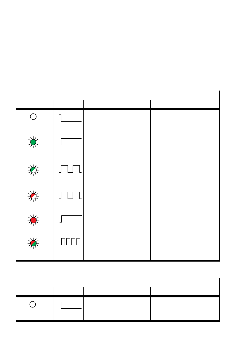
4. Diagnostics
4.2.3 Protocol-specific LEDs
EtherNet/IP protocol
Module status when using the EtherNet/IP protocol
LED MS Sequence Status Significance/error handling
Does not
ON
OFF
Logic supply for bus interface
not applied
• Check logic supply
illuminate
ON
OFF
Operating status normal None
Illuminates
green
ON
OFF
Flashes green
ON
OFF
CPX terminal must be placed in
operation as the configuration
• Carry out, complete or correct
the configuration
is missing, incomplete or
incorrect.
Error can be rectified • Complete or correct the
configuration
Flashes red
ON
OFF
Illuminates red
ON
OFF
Error cannot be rectified • Check CPX expansion as well
as other LEDs and, if
necessary, request service
CPX terminal is in self-test None
Flashes
red-green
Tab. 4/10: LED display MS (module status) for EtherNet/IP protocol
Network status when using the EtherNet/IP protocol
LED NS Sequence Status Significance/error handling
Does not
ON
OFF
The CPX terminal is offline • Check network connection
illuminate
Tab. 4/11: LED display NS (network status) for EtherNet/IP protocol - Part 1
4-10
Festo P.BE-CPX -FB36-EN en 1309NH English
Page 99
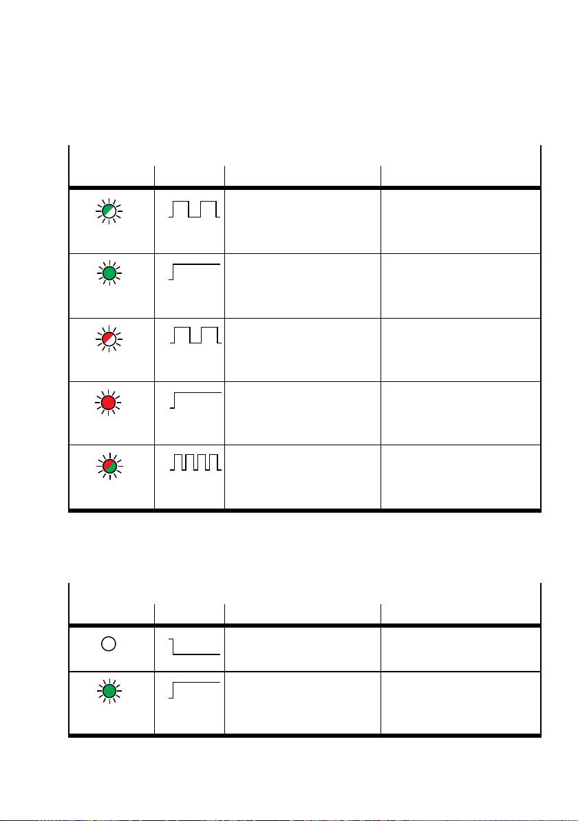
4. Diagnostics
Network status when using the EtherNet/IP protocol
LED NS Sequence Status Significance/error handling
ON
OFF
Flashes green
ON
OFF
Illuminates
CPX terminal is online and has
received an IP address, but the
CPX terminal does not have a
configured connection.
The CPX terminal is online and
has a connection to the
fieldbus
• Check configuration; it is
possible that the CPX
terminal is not assigned to a
master/scanner or
None (normal operating status)
green
ON
OFF
Flashes red
ON
OFF
Illuminates red
ON
OFF
Oneormore“I/Oconnections”
are in the time-out status
• Check the physical
connection to the
master/scanner (EtherNet
cable).
Communicationhas failed.
• Correct IP address
– Non-permittedIPaddress
set and already used in the
network
CPX terminal is in self-test None
Flashes
red/green
Tab. 4/12: LED display NS (network status) for EtherNet/IP protocol - Part 2
Modbus/TCP protocol
Module status when using the Modbus/TCP protocol
LED MS Sequence Status Significance/error handling
Is off
ON
OFF
ON
OFF
Not ready for Modbus connections
Ready for Modbus connections –
–
Illuminates
green
Tab. 4/13: LED display MS (module status) for Modbus/TCP protocol - Part 1
Festo P.BE-CPX-F B36-EN en 1309NH English
4-11
Page 100
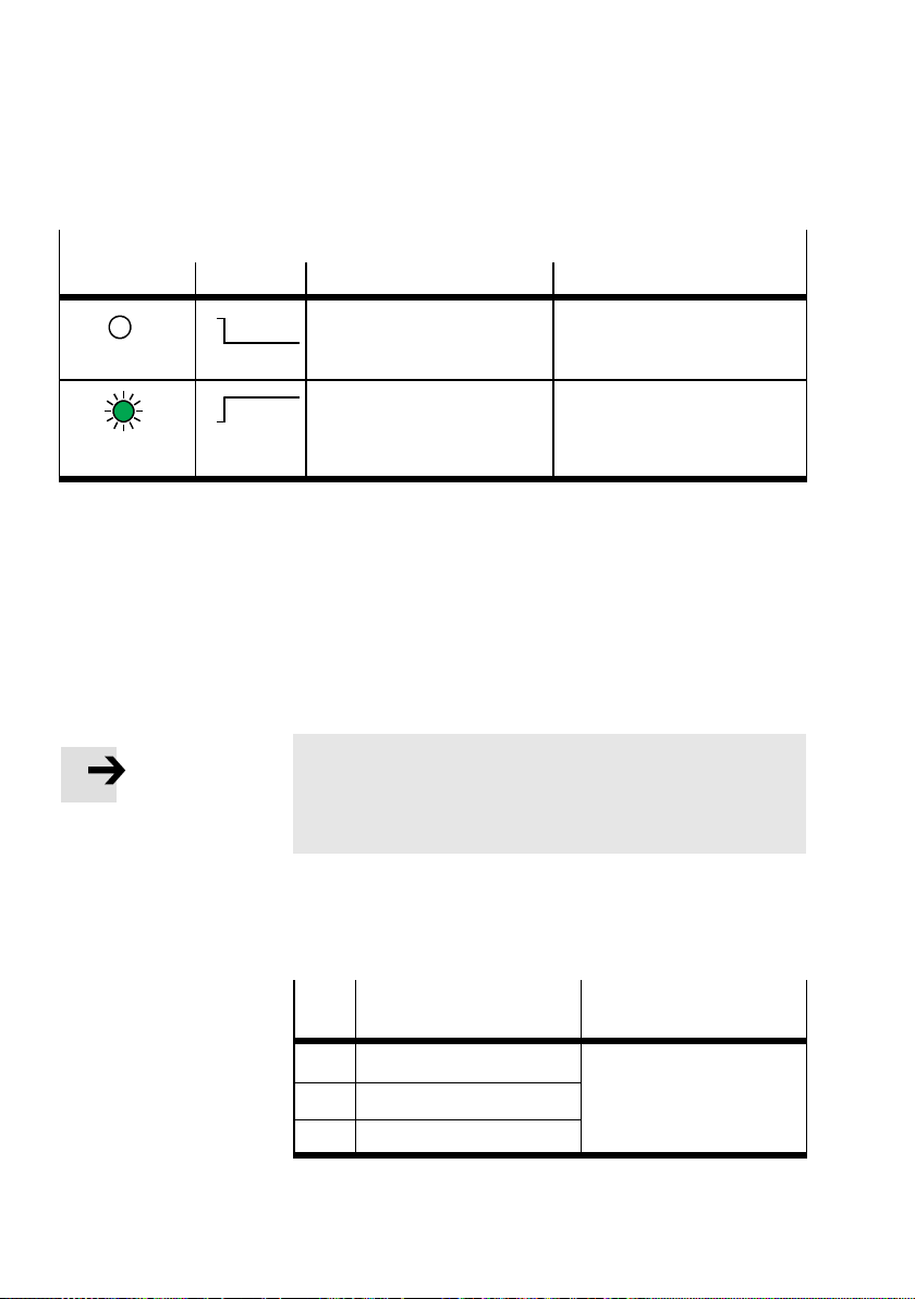
4. Diagnostics
Network status when using the Modbus/TCP protocol
LED NS Sequence Status Significance/error handling
ON
OFF
Is off
ON
OFF
Illuminates
green
No Modbus connection active –
At least one Modbus
connection active.
–
Tab. 4/14: LED display MS (module status) for Modbus/TCP protocol - Part 2
4.3 Diagnostics via status bits
Status bits are internal inputs (1 input byte), which serve to
display common diagnostic messages (global error messages).
Note
If status bits are to be transmitted via a “Polled” or
“Change of state” connection, you must set the DIL
switches on the bus node accordingly ( Tab. 1/2).
If all status bits supply logic 0, no error will be reported. The
following table shows the diagnostic information when there
is a 1-signal:
4-12
Bit
Diagnostic information
Description
with logic 1
0 Error at valve Moduletypeinwhichan
1 Error at output
2 Error at input
error has occurred
Tab . 4/15: Overview of status bits - Part 1
Festo P.BE-CPX -FB36-EN en 1309NH English
 Loading...