

Page 1
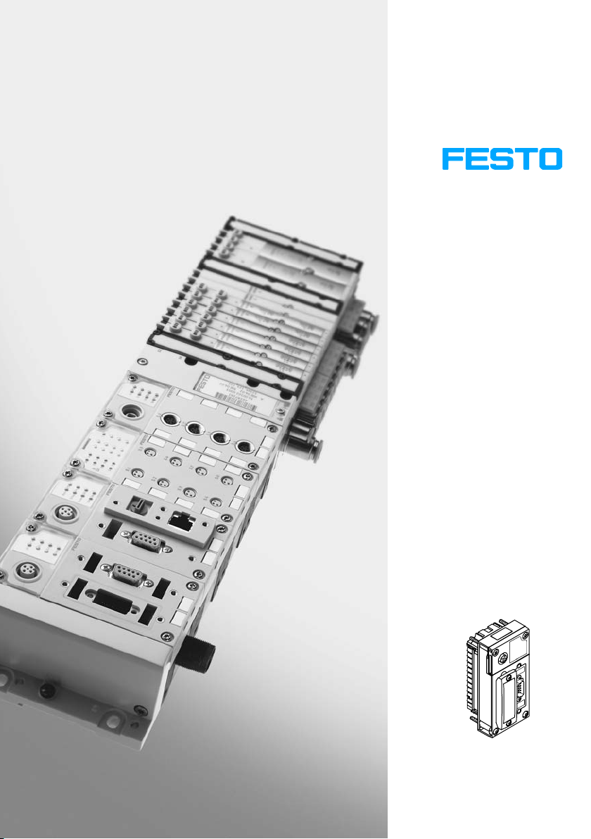
CPX Terminal
Electronics Manual
CPX Fieldbus Node
Type CPX−FB14
Fieldbus Protocol
CANopen
Manual
526 410
en 0810b
[740 276]
Page 2

Page 3

Contents and general instructions
Original de. . . . . . . . . . . . . . . . . . . . . . . . . . . . . . . . . . . . . . .
Edition en 0810b. . . . . . . . . .
. . . . . . . . . . . . . . . . . . . . . . . .
Designation P.BE−CPX−FB14−EN. . . . . . . . . . . . . . . . . . . . . . .
Order no. 526 410
. . . . . . . . . . . . . . . . . . . . . . . . . . . . . . . . .
© (Festo AG&Co. KG, D73726 Esslingen, Germany, 2009)
Internet: http://www.festo.com
E−Mail: [email protected]
The reproduction, distribution and utilization of this docu−
ment as
well as the comunication of its contents to others
without express authorization is prohibited. Offenders will
be held liable for the payment of damages. All rights re−
served in the event of the grant of a patent, utility module
or design.
Festo P.BE−CPX−FB14−EN en 0810b
I
Page 4

Contents and general instructions
®
TORX
is a registered trade mark
of Acument Intellectual Properties, LLC
(Manufacturer: Acument Global Technologies
NorthAmerica, Sterling Heights, Michigan, USA)
II
Festo P.BE−CPX−FB14−EN en 0810b
Page 5

Contents and general instructions
Contents
Intended use VII . . . . . . . . . . . . . . . . . . . . . . . . . . . . . . . . . . . . . . . . . . . . . . . . . . . . . . . . . .
Target group VII . . . . . . . . . . . . . . . . . . . . . . . . . . . . . . . . . . . . . . .
Service VII . . . . . . . . . . . . . . . . . . . . . . . . . . . . . .
Notes on this manual VIII . . . . . . . . . . . . . .
Important user instructions IX . . . . . . . . . .
. . . . . . . . . . . . . . . . . . . . . . . . . . . . . . . . .
. . . . . . . . . . . . . . . . . . . . . . . . . . . . . . . . . . . . .
. . . . . . . . . . . . . . . . . . . . . . . . . . . . . . . . . . . .
. . . . . . . . . . . . . . . . . . .
1. Installation 1−1 . . . . . . . . . . .
1.1 General instructions on installation 1−3 . . . . . .
1.2 Settings of the DIL switches on the field bus node 1−7 . . . . . . . . . . . . . . .
1.2.1 Removing and fitting the cover over the DIL switches 1−7 . . . . . . . . . . .
1.2.2 Setting the DIL switches 1−8 . . . . . . . . . . . . . . . . . . . . .
1.3 Connecting the field bus 1−20 . . . . . . . . . . . . . . . . . . . . . . . . . . . . . . . . . .
1.3.1 Field bus cable 1−20 . . . . . . . . . . . . . . . . . . . . . . . . . . . . . . . . . . . . . . . .
1.3.2 Field bus baud rate and field bus length 1−21 . . . . . . . . . . . . . . . . . . . . .
1.3.3 Information on connecting the field bus 1−22 . . . . . . . . . . . . . .
1.3.4 Field bus interface 1−24 . . . . . . . . . . . . . . . . . . . . . . . . . . . . . . . . . . . . . . .
1.3.5 Connecting
1.3.6 Further connection possibilities for the field bus
with adapters 1−27 . . . . . . . . . . . . . . . . . . .
1.4 Bus terminal with terminating resistors 1−30 . . . . . . . . . . . . . . . . . . . . .
1.4.1 Install a terminating resistor using the adapters 1−30 . . . . . . . . . . . . . . .
1.5 Pin assignment of power supply 1−31 . . . . . . . . . . . . . . . .
. . . . . . . . . . . . . . . . . . . . . . . . . . . . . . . . . . . . . . . .
. . . . . . . . . . . . . . . . . . . . . . . . . .
. . . . . . . . . . . . .
. . . . . . .
. . . . . . .
with the field bus plug from Festo 1−25 . . . . . . . . . . . . . . . .
. . . . . . . . . . . . . . . . . . . . . . . .
. . . . . . . .
. . . . . . . . . . . . . . . . . . .
. . . . .
. .
Festo P.BE−CPX−FB14−EN en 0810b
III
Page 6

Contents and general instructions
2. Commissioning 2−1 . . . . . . . . . . . . . . . . . . . . . . . . . . . . . . . . . . . . . . . . . . . . . . . .
2.1 Commissioning on a CANopen master 2−3 . . . . . . . . . . . . . . . . . . . . . . . . . . . . . .
2.1.1 General information on CANopen 2−4 . . . . . . . . . .
2.2 Configuration 2−5 . . . . . . . . . . . . . . . . . . . . . . . . . . . . . . . . .
. . . . . . . . . . . . . . . . .
. . . . . . . . . . . . . . . . .
2.2.1 Addressing the CPX terminal 2−5 . . . . . . . . . . . . . . . . . . . . . . . . . . . . .
2.2.2 Configuration examples 2−8 . . . . . . . . . . . . . . . . . . . . . . . . . . . . . . . . . .
2.3 Overview 2−14 . . . . . . . . . . . . .
2.3.1 Brief overview of the scope of functions 2−14 . .
2.3.2 Overview Object directory 2−15 . . . . . . . . . . . . . . . . . . . . . . . . . . . . .
. . . . . . . . . . . . . . . . . . . . . . . . . . . . . . . . . . . . . . . . .
. . . . . . . . . . . . . . . . . . .
. . .
2.3.3 Reaction of the CPX terminal when it is switched on 2−16 . . . . . . . . . . . .
2.3.4 Default identifier distribution 2−18 . . . . . . . . . . . . . . . . . . . . . .
2.4 Object directories 2−20 . . . . . . . . . . . . . . . . . . . . . . . . . . . . . . . . . . . . . . . . .
. . . . . . . .
. . . . . .
2.4.1 Communication profile 2−20 . . . . . . . . . . . . . . . . . . . . . . . . . . . . . . . . . . .
2.4.2 Overview of the PDO structure 2−25 . .
2.4.3 Digital inputs (transmit PDO 1) 2−26 . . . . . . . . . . . . . . . . . . .
. . . . . . . . . . . . . . . . . . . . . . . . . . .
. . . . . . . . . .
2.4.4 Digital outputs (receive PDO 1) 2−28 . . . . . . . . . . . . . . . . . . . . . . . . . . . .
2.4.5 Analogue inputs channel 0 Ū 3 (transmit
PDO 2) 2−33 . . . . . . . . . . . . . .
2.4.6 Analogue outputs channel 0 Ū 3 (Receive PDO 2) 2−38 . . . . . . . . . . . . .
2.4.7 Analogue inputs channel 4 Ū 15 (Transmit PDO 3) 2−40 . . . .
. . . . . . . . .
2.4.8 Analogue outputs channel 4 Ū 15 (Receive PDO 3) 2−43 . . . . . . . . . . . .
2.4.9 Technology modules, status bits, I/O diagnostic interface
(PDO 4) 2−45 . . . . . . . . . . .
2.4.10 Manufacturer specific profile 2−49 . . . . . . . . . . .
. . . . . . . . . . . . . . . . . . . . . . . . . . . . . . . . . . . . .
. . . . . . . . . . . . . . . . . . .
2.4.11 Overview of mappingobjects 2−56 . . . . . . . . . . . . . . . . . . . . . . . . . . . .
2.4.12 Force 2−58 . . . . . . . . . . . . . . . . . . . . . . . . . . . . . . . . . . . . . . . . . . . . . . . .
. .
2.4.13 Function assignment and virtual modules 2−62 . . . . . . . . . . . . . . . . . . . .
2.5 Parameterizing 2−68 . . . . . . . . . . . . . . . . . . . . . .
2.5.1 Parameterizing when switching on 2−68 . . . . . . . . . . . . . . . . . . . .
. . . . . . . . . . . . . . . . . . . . . . . . . . .
. . . . . .
2.5.2 Parameterization with the handheld 2−69 . . . . . . . . . . . . . . . . . . . . . . . .
2.5.3 Application example for parameterization 2−69 . . . . . . . . . . . .
. . . . . . . .
2.6 Commissioning the CPX terminal in the system 2−70 . . . . . . . . . . . . . . . . . . . . . . .
2.6.1 Error−free commissioning, normal operating status 2−70 . . . . . . . .
. . . .
.
. .
IV
Festo P.BE−CPX−FB14−EN en 0810b
Page 7

Contents and general instructions
3. Diagnosis 3−1 . . . . . . . . . . . . . . . . . . . . . . . . . . . . . . . . . . . . . . . . . . . . . . . . . . . . .
3.1 Overview of diagnostic possibilities 3−3 . . . . . . . . . . . . . . . . . . . . . . . . . . . . . . . .
3.2 Diagnostics via LEDs 3−4 . . . . .
3.2.1 Normal operating status 3−5 . . . . . . . . .
. . . . . . . . . . . . . . . . . . . . . . . . . . . . . . . . . . . . . . .
. . . . . . . . . . . . . . . . . . . . . . . . .
3.2.2 Error displays of the CPX−specific LEDs PS, PL, SF, M 3−6 . . . . . . . . . . .
3.2.3 Error displays of the
3.3 Diagnosis via status bits 3−11 . . . . . . . . . . . . . . . . . . . . . . . . . . . . . . . . . .
CANopen−specific LEDs MS, NS, IO 3−9 . . . . . . . .
. . . . . . .
3.4 Diagnosis via the I/O diagnostic interface 3−12 . . . . . . . . . . . . . . . . . . . . . . . . . . .
3.5 Diagnosis via CANopen 3−13 . . . . . . .
3.5.1 The emergency message 3−14 . . . . . . . . . . . . .
3.5.2 CPX fault numbers 3−19 . . . . . . . . . . . . . . . . . . . . . . . . . .
. . . . . . . . . . . . . . . . . . . . . . . . . . . . . . . . . . .
. . . . . . . . . . . . . . . . . . . . .
. . . . . . . . . . . . .
A. Technical appendix A−1 . . . . . . . . . . . . . . . . . . . . . . . . . . . . . . .
. . . . . . . . . . . . . .
A.1 Technical data of fieldbus node CPX−FB14 A−3 . . . . . . . . . . . . . . . . . . . . . . . . . . .
A.2 Examples: Communication sequence A−4 .
A.2.1 Example 1: Start CANopen network A−4 . . . . . . . . . . . . . . .
. . . . . . . . . . . . . . . . . . . . . . . . . . . . . .
. . . . . . . . . .
A.2.2 Example 2: Set output A−4 . . . . . . . . . . . . . . . . . . . . . . . . . . . . . . . . . . . .
A.2.3 Example
A.2.4 Example 4: Load objects A−6 . . . . . . . . . . . . . . . . . . . . . .
3: Start Node guard" monitoring A−5 . . . . . . . . . . . . . . . . . . .
. . . . . . . . . . . .
A.2.5 Example 5: Write objects A−7 . . . . . . . . . . . . . . . . . . . . . . . . . . . . . . . . .
A.3 Example: Parameterization
B. Index B−1 . . . . . . . . . . . . . . . . . . . . . . . . . . . . .
with the program CANsetter" A−8 . . . . . . . . . . . . . .
. . . . . . . . . . . . . . . . . . . . . . . . . . . .
Festo P.BE−CPX−FB14−EN en 0810b
V
Page 8

Contents and general instructions
VI
Festo P.BE−CPX−FB14−EN en 0810b
Page 9

Contents and general instructions
Intended use
The field bus node type CPX−FB14 described in this manual
has been designed exclusively for use as a slave on the
CANopen field bus.
The CPX terminal must only be used as follows:
as intended
in original condition
without unauthorised modifications
In faultless technical condition.
The limit values specified for pressures, temperatures,
Please comply with the regulations of the workers’
compensation insurance association, the German Technical
Control Board (TÜV) and the electrical requirements of the
VDE or the corresponding national and local safety
regulations.
electrical data, torques
etc. should be observed.
Target group
Service
Festo P.BE−CPX−FB14−EN en 0810b
This manual is intended exclusively for technicians trained in
control and automation technology who have experience in
installing, commissioning, programming and diagnosing
slaves on the CANopen field bus.
Please consult your local Festo repair service if you have any
technical problems.
VII
Page 10
Contents and general instructions
Notes on this manual
This manual contains specific information on installing,
configuring, parameterizing, commissioning, programming
and diagnosing with the CPX field bus node for CANopen.
This manual refers to the following versions:
Versions
Rev 24 (19 Nov. 08)
Rev 20 (10 Oct. 07)
Rev 14 (12 Jul. 05) CPX−FEC
EDS file from 1 Sep. 08
1)
1)
Software status (SW) or revision no. (R) see type plate
Support of
Virtual modules via the Function
Assignment Object (see section 2.4.13)
CPX−CP interface
Tab.0/1: Revisions of the CPX−FB14 until December 2008
An overview of the structure of the CPX terminal user
documentation is contained in the CPX system
description.
General basic information about the method of operation,
fitting,
installing and commissioning CPX terminals can be
found in the CPX system description.
Information about further CPX modules can be found in the
manual for the respective module.
VIII
Festo P.BE−CPX−FB14−EN en 0810b
Page 11
Contents and general instructions
Important user instructions
Danger categories
This manual contains instructions on the possible dangers
which may occur if the product is not used correctly. These
instructions are marked (Warning, Caution, etc.), printed on a
shaded background and marked additionally with a picto
gram. A distinction is made between the following danger
warnings:
Warning
This means that failure to observe this instruction may
result in serious personal injury or damage to property.
Caution
This means that failure to observe this instruction may
result in personal injury or damage to property.
Festo P.BE−CPX−FB14−EN en 0810b
Note
This means that failure to observe this instruction may
result in damage to property.
The following pictogram marks passages in the text which
describe activities with electrostatically sensitive compo
nents.
Electrostatically sensitive components may be damaged if
they are not handled correctly.
IX
Page 12
Contents and general instructions
Marking special information
The following pictograms mark passages in the text
containing special information.
Pictograms
Information:
Recommendations, tips and references to other sources of
information.
Accessories:
Information on necessary or sensible accessories for the
Festo product.
Environment:
Information on environment−friendly use of Festo products.
Text markings
· The bullet indicates activities which may be carried out in
any order.
1. Figures denote activities which must be carried out in the
numerical order specified.
Hyphens indicate general activities.
X
Festo P.BE−CPX−FB14−EN en 0810b
Page 13
Contents and general instructions
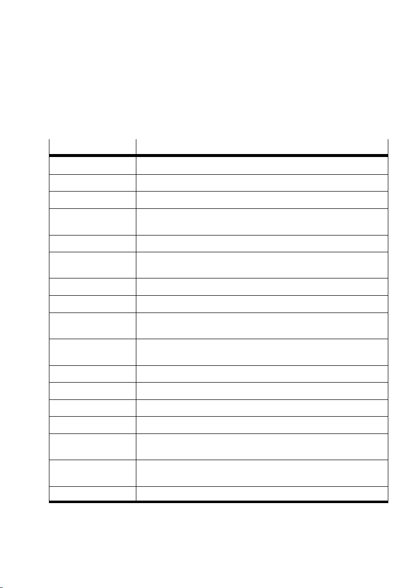
The following product−specific terms and abbreviations are
used in this manual:
Term / abbreviation
AO, AI Analogue output, analogue input
COB Communication object identifier
CPX terminal Complete system consisting of CPX modules with or without pneumatics
DIL switch Dual−in−line switches consist of several switch elements with which
F0
h
Field bus node Provides the connection to specific fieldbuses. They transmit control
Handheld Handheld programmer for commissioning and service purposes (CPX−MMI)
I/Os Digital inputs and outputs
I/O diagnostic interface The I/O diagnostic interface is a bus−independent diagnostic interface at
I/O modules Collective term for the CPX modules which provide digital inputs and
IW / OW Input Word / Output Word
O, I Digital output, digital input
OB Output byte
PLC/IPC Programmable logic controller/industrial PC
Meaning
settings can be made
Hexadecimal numbers are marked by a low−set h"
signals to the connected modules and monitor their functioning
I/O level, permitting access to internal data of the CPX terminal
outputs
Pneumatic interface The pneumatic interface is the interface between the modular electrical
SC/O
SCS, SCO, SCV
Status bits Internal inputs which supply coded common diagnostic messages.
periphery and the pneumatics
Short circuit/overload
Short circuit/overload sensor supply, outputs, valves
Tab.0/2: Product−specific terms and abbreviations
Festo P.BE−CPX−FB14−EN en 0810b
XI
Page 14

Contents and general instructions
XII
Festo P.BE−CPX−FB14−EN en 0810b
Page 15

Installation
Chapter 1
1−1Festo P.BE−CPX−FB14−EN en 0810b
Page 16

1. Installation
Contents
1. Installation 1−1 . . . . . . . . . . . . . . . . . . . . . . . . . . . . . . . . . . . . . . . . . . . . . . . . . . .
1.1 General instructions on installation 1−3 . . . . . . . . . . . . . . . . . . . . . . . . . . . . . . . .
1.2 Settings of the DIL switches on the field bus node 1−7
1.2.1 Removing and fitting the cover over the DIL switches 1−7 . . . . . . . . . . .
1.2.2 Setting the DIL switches 1−8 . . . . . . .
1.3 Connecting the field bus 1−20 . . . . . . . . . . . . . . . . . . .
1.3.1 Field bus cable 1−20 . . . . . . . . . . . . . . . . . . . . . . . . . .
1.3.2 Field bus baud rate and field bus length 1−21 . . . . . . . . . . . . . . . . . . . . .
1.3.3 Information on connecting the field
1.3.4 Field bus interface 1−24 . . . . . . . . . . . . . . . . . . . . . . . . . .
1.3.5 Connecting with the field bus plug from Festo 1−25 . . . . . . . . . . . . . . . .
1.3.6 Further connection possibilities for the field bus with adapters 1−27 . .
1.4 Bus terminal
1.4.1 Install a terminating resistor using the adapters 1−30 . . . . . . . . . . . .
1.5 Pin assignment of power supply 1−31 . . . . . . . . . . . . . . . . . . . . . . . . . . . . . . . . . . .
with terminating resistors 1−30 . . . . . . . . . . . . . . . . . . . . . . . . . . . . .
. . . . . . . . . . . . . . . . . . . . . . . . . . .
. . . . . . . . . . . . . . . . . . . .
. . . . . . . . . . . . . . . . . . . . . .
. . . . . . . . . . . . . . . .
bus 1−22 . . . . . . . . . . . . . . . . . . . . .
. . . . . . . . . . . . .
. . .
1−2
Festo P.BE−CPX−FB14−EN en 0810b
Page 17
1. Installation
1.1 General instructions on installation
Warning
Before carrying out installation and maintenance work,
switch off the following:
compressed air supply
the operating voltage supply for the electronics/sensors
the load voltage supply fo
In this way, you can avoid:
uncontrolled movements of loose tubing.
unexpected movements of the connected actuators
r the outputs/valves.
Festo P.BE−CPX−FB14−EN en 0810b
non−defined switching states
of the electronic
components.
Caution
The CPX field bus node contains electrostatically sensitive
components.
· Therefore, do not touch any components.
· Observe the handling specifications for electrostatically
sensitive components.
They will help you avoid damage to the electronics.
Information about fitting the CPX terminal can be
found in the
CPX system manual (P.BE−CPX−SYS−...).
1−3
Page 18
1. Installation
Electrical connection and display elements
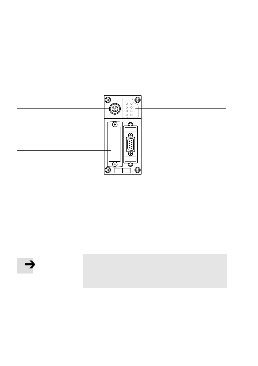
The following connecting and display elements can be found
on the CPX field bus node for CANopen:
MS PS
PL
NS
SF
IO
4
M
3
1 Bus−status−specific and CPX−specific
LEDs
3 Transparent cover for the DIL switches
4 Service interface for handheld
2 Field bus connection
(9−pin Sub−D plug)
Fig.1/1:Connecting and display elements on the CPX field bus node
Note
Use protective caps or blanking plugs to seal unused
connections. You will then comply with protection class
IP65/IP67.
1
2
1−4
Festo P.BE−CPX−FB14−EN en 0810b
Page 19

1. Installation
Dismantling and fitting
The field bus node is fitted in an interlinking block of the CPX
terminal (see Fig.1/2).
Dismantling Dismantle the field bus node as follows:
1. Loosen the 4 screws in the field bus
screwdriver size T10.
2. Pull the field bus node carefully and without tilting away
from the contact rails of the manifold base.
1 Field bus node
CPX−FB14
4
2 Interlocking block
3 Contact rails
4 TORX T10 screws
3
Fig.1/2: Dismantling/fitting the field bus node
node with a TO RX
1
2
Festo P.BE−CPX−FB14−EN en 0810b
1−5
Page 20
1. Installation
Note
Always use the correct screws for the interlocking block,
which depend on whether the block is made of metal or
plastic.
For plastic interlocking blocks: thread−cutting s
For metal interlocking blocks: screws with metric thread.
Both types of screws are enclosed respectively when ordering
the bus node as a single part.
Fitting Fit the field bus node as follows:
1. Check seal and seal surfaces
2. Place the field bus node in the interlocking block.
Make sure that the grooves with the power contact
terminals on the bottom o
f the field bus node lie above
the contact rails.
crews
1−6
3. Press the field bus node carefully and without tilting as
far as possible into the interlocking block.
4. Tighten the screws at first only b
y hand. Place the screws
so that the self−cutting threads can be used.
5. Tighten the screws with a TORX screwdriver size T10
with 0.9 Ū 1.1 Nm.
Festo P.BE−CPX−FB14−EN en 0810b
Page 21
1. Installation
1.2 Settings of the DIL switches on the field bus node
In order to set the CPX field bus node, you must first remove
the cover over the DI L switches.
Caution
The CPX field bus node contains electrostatically sensitive
components.
· Do not therefore touch any contacts.
· Observe the handling specifications for electrostatically
sensitive components.
You will then prevent the electronics in the node from being
damaged.
1.2.1 Removing and fitting the cover over the DIL switches
In order to set the CPX field bus node, you must first remove
the cover over the DI L switches.
Removing 1. Switch off the power supply.
2. Unscrew the two fastening screws in
3. Remove the cover.
Fitting 1. Place the cover carefully on the node.
Note
· Make sure that the seal is seated correctly.
2. Tighten the two fastening screws at first by hand and then
with torque 0.4Nm.
Festo P.BE−CPX−FB14−EN en 0810b
the switch cover.
1−7
Page 22

1. Installation
1.2.2 Setting the DIL switches
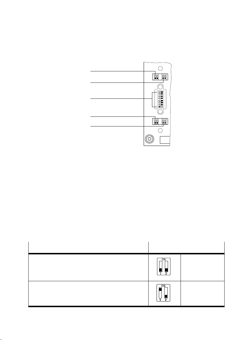
When the cover over the DIL switches is removed, you will see
5DIL switches in the field bus node (see Fig.1/3).
You can set the following parameters with the DIL swit
ches:
operating mode
fault mode
station number
baud rate
CPX diagnostic mode.
Procedure:
1. Switch off the power supply.
2. Remove the cover over the DIL switches (section1.2.1).
the desired operating mode (DIL switch1, factory
3. Set
setting: remoteI/O).
4. Set the error mode (DI L switch2).
5. Assign an unused station number to the CPX terminal.
Set the desired station
number (8−position DIL switch3,
switch elements 1Ū7).
6. Set the baud rate (DIL switch4).
1−8
7. Operating mode RemoteI/O:
Set the CPX diagnostic mode (DIL switch5).
operating mode Remote Controller:
With
Set the required number of logical I/Os of the CPX−FB14
(DIL switch 5).
8. Fit the cover again (section1.2.1).
Festo P.BE−CPX−FB14−EN en 0810b
Page 23
1. Installation
1 DIL switch 1:
Operation mode
2 DIL switch 2:
1
2
Undervoltage
error message
3
mode
3 DIL switch 3:
Station number
4 DIL switch 4:
Baud rate
4
5
5 DIL switch 5:
CPX diagnosis
mode or number
of logical I/Os
with Remote
Controller"
Fig.1/3: DIL switch in the field bus node
(further information on
1Ū5 in the following)
Setting the operating mode with DIL switch
You can set the operating mode of the field bus node with
switch element 1 of DIL switch 1:
ON ON
12 12
ON
ON ON
12 12
8
12 34 56 7
1
Operating mode
Remote I/O operating mode
All functions of the CPX terminal are controlled directly by
the CANopen Master. An FEC built into the CPX terminal
functions like a passive function module without a controller.
Remote controller operating mode
An FEC integrated in the CPX terminal takes control of the
I/Os. This operating mode is only useful if an FEC is
integrated in the CPX terminal.
Tab.1/1: DIL switch 1 (operating mode)
Festo P.BE−CPX−FB14−EN en 0810b
Setting DIL switch 1
DIL 1.1: OFF
DIL 1.2: OFF
(factory setting)
DIL 1.1: ON
DIL 1.2: OFF
1−9
Page 24
1. Installation
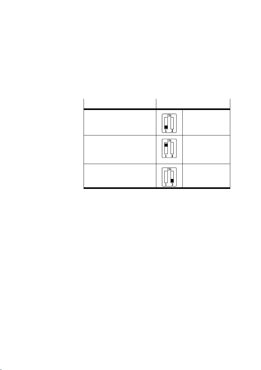
Setting the error mode with DIL switch2
You set the error mode with switch element 1 of the
2−element DIL switch 2:
Error mode
Registering undervoltage error 2.1: OFF
Filtering undervoltage error
Errors during monitoring of the
operating and load voltage
supplies are ignored
Reserved 2.2:Always OFF
Setting DIL switch 2
(factory setting)
2.1: ON
Tab.1/1: DIL switch 2 (Undervoltage" error message)
With the setting Filter undervoltage", voltage errors which
occur will not be reproted as errors. In this way, you can,
for
example, suppress unnecessary error messages during the
commissioning phase.
The setting of the DIL switch has precedence over the para
meterizing of defined settings. No emergency message is
transmitted with error filtering.
1−10
Festo P.BE−CPX−FB14−EN en 0810b
Page 25
1. Installation
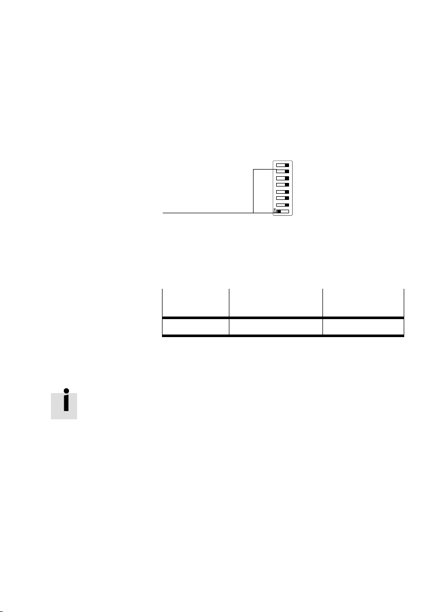
1 Setting of station
numbers (switch
elements 1Ū7)
Setting the station number with DIL switch 3
You can set the station number of the CPX terminal binary
coded with the 8−element DIL switch 3.
1
Fig.1/4: DIL switch 3 (station number)
The following station numbers are permitted:
Protocol
CANopen Station number 1; ...; 127
Tab.1/2: Permissible station numbers
Recommendation:
Assign the station numbers in ascending order. Assign the
station numbers in accordance with the machine structure of
your system.
1234 5678
Address designation Permissible
station numbers
Festo P.BE−CPX−FB14−EN en 0810b
1−11
Page 26
1. Installation
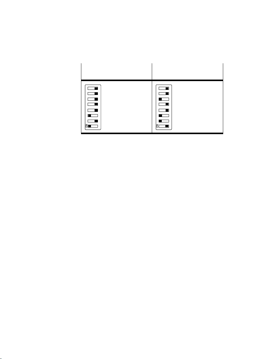
Example: Station number
set: 05
20 + 22 =
1234 5678
1 + 4 =
5
Example: Station number
set: 38
21 + 22 + 25 =
2 + 4 + 32 =
1234 5678
38
Tab.1/3: Examples of set station numbers
(binary coded)
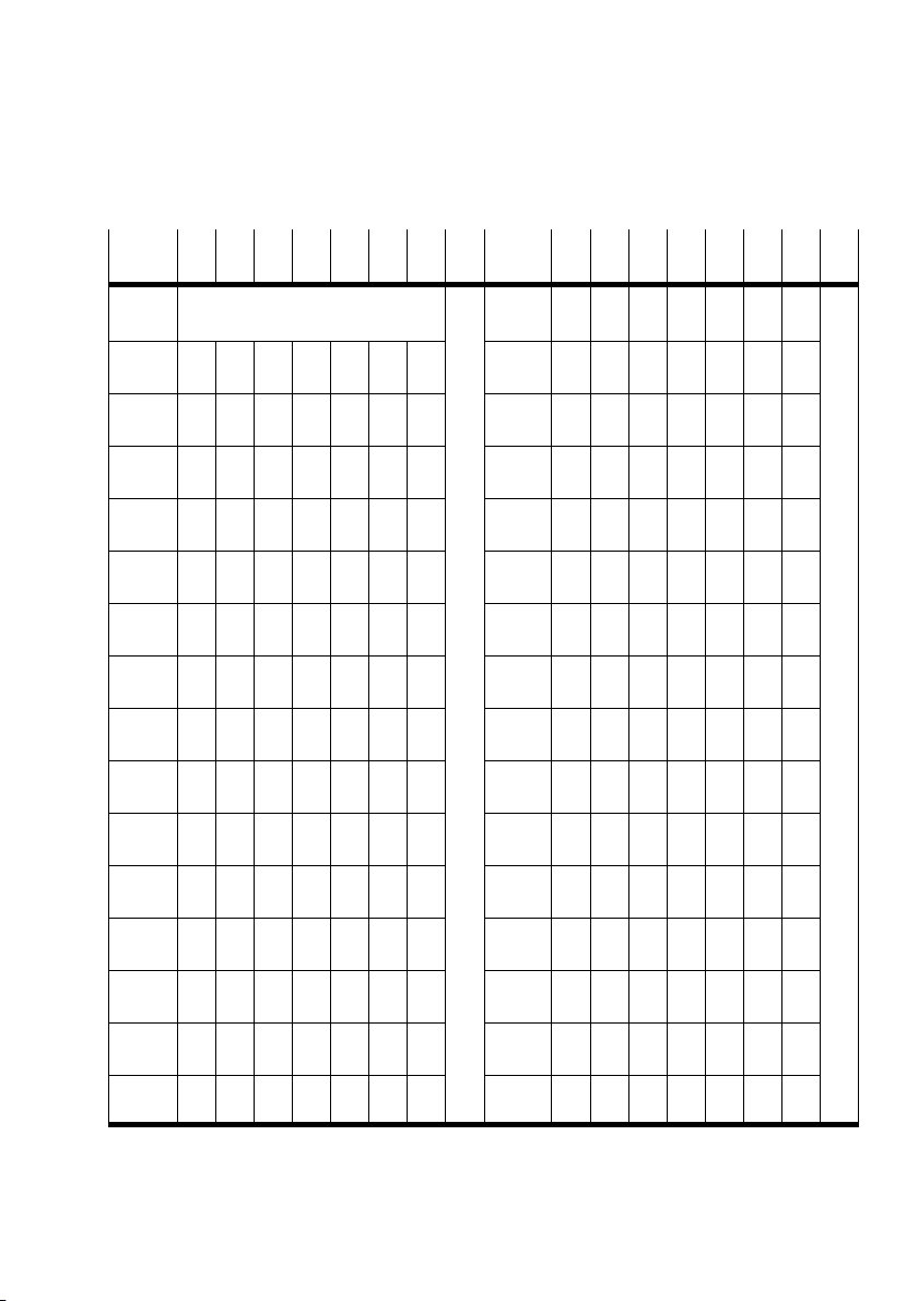
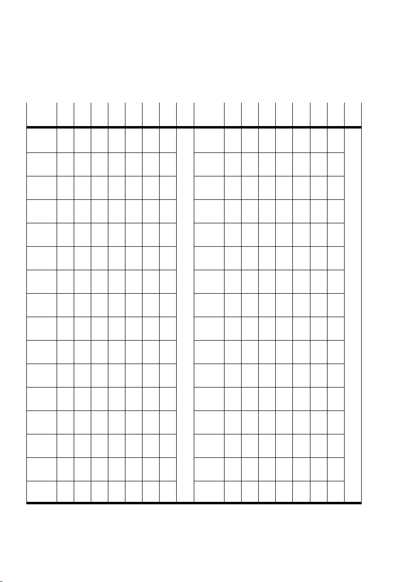
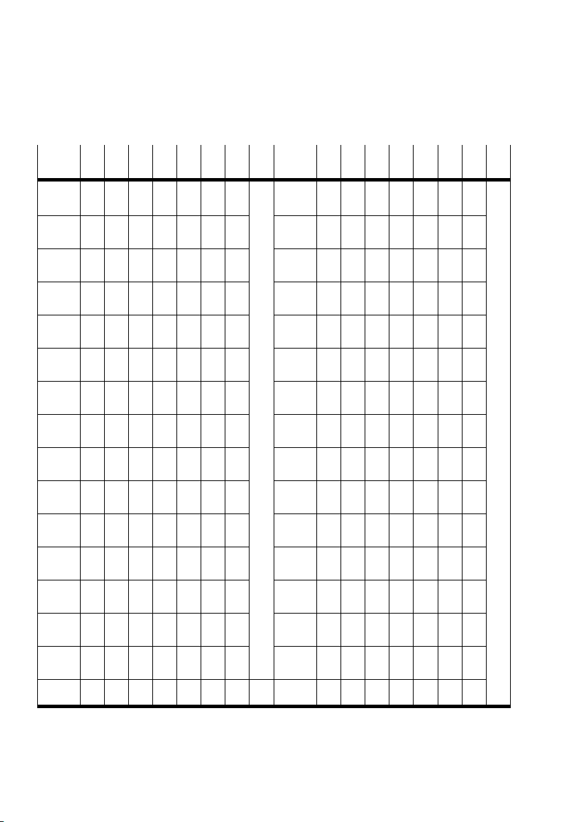
On the following pages you will find an overview of the station
number settings.
1−12
Festo P.BE−CPX−FB14−EN en 0810b
Page 27
1. Installation
Station
no.
0
1
2
3
4
5
6
7
8
9
10
11
12
13
14
15
1 2 3 4 5 6 7 8
Not permitted
ON
OFF OFF OF F OFF OFF OFF
ON
OFF
ON ON
OFF OFF
ON
OFF
ON ON ON
OFF OFF OF F
ON
OFF
ON ON
OFF OFF
ON
OFF
ON ON ON ON
OFF OFF OF F OFF OFF
OFF OFF OF F OFF OFF
ON
OFF OFF OF F OFF
ON
OFF
ON ON
OFF OFF
ON
OFF
ON ON ON
OFF OFF OF F OFF
OFF OFF OF F OFF
OFF OFF OF F OFF
ON
OFF OFF OF F
ON
OFF OFF OF F
ON
OFF
OFF
ON ON
ON ON
OFF OFF OF F
ON
OFF OFF OF F
OFF OFF OF F
OFF OFF OF F
OFF OFF OF F
OFF OFF OF F
Station
no.
16
17
18
19
20
21
22
23
24
25
26
27
28
29
30
31
1 2 3 4 5 6 7 8
OFF
OFF
OFF
OFF
ON ON
ON ON
ON ON
ON ON
ON
OFF OFF
ON
OFF OFF
ON
OFF OFF
ON
OFF OFF
ON
OFF OFF
ON
OFF OFF
ON
OFF OFF
ON
OFF OFF
OFF OFF
OFF OFF
OFF OFF
OFF OFF
OFF OFF
OFF OFF
OFF OFF
OFF OFF
OFF OF F OFF OFF
ON
OFF OFF OF F
ON
OFF
ON ON
OFF OF F
ON
OFF
ON ON ON
OFF OF F OFF
ON
OFF
ON ON
OFF OF F
ON
OFF
ON ON ON ON ON
OFF OFF
OFF OFF
ON
ON
OFF
ON ON
OFF OFF
ON
OFF
OFF
ON ON ON
ON ON ON
OFF
ON ON ON ON
Tab.1/4: Setting of station numbers 1 Ū 31: Position of the DIL switch elements
Festo P.BE−CPX−FB14−EN en 0810b
1−13
Page 28
1. Installation
Station
no.
32
33
34
35
36
37
38
39
40
41
42
43
44
45
46
47
1 2 3 4 5 6 7 8
OFF
OFF
OFF
OFF
OFF
OFF
OFF
OFF
ON
OFF
ON
OFF
ON
OFF
ON
OFF
ON
OFF
ON
OFF
ON
OFF
ON
OFF
ON
OFF
ON
OFF
ON
OFF
ON
OFF
ON
OFF
ON
OFF
ON
OFF
ON
OFF
OFF OFF OF F OFF OFF
ON
OFF OFF OF F OFF
ON
OFF
ON ON
OFF OFF
ON
OFF
ON ON ON
OFF OFF OF F
ON
OFF
ON ON
OFF OFF
ON
OFF
ON ON ON ON
OFF OFF OF F
OFF OFF OF F
ON
ON
OFF
ON ON
OFF OFF
ON
OFF
OFF
ON ON
ON ON
OFF
ON ON ON
OFF OFF
OFF OFF
OFF OFF
OFF OFF
ON
ON
ON
ON
Station
no.
48
49
50
51
52
53
54
55
56
57
58
59
60
61
62
63
1 2 3 4 5 6 7 8
OFF OF F OFF OFF
ON
OFF OFF OF F
ON
OFF
ON ON
OFF OF F
ON
OFF
ON ON ON
OFF OF F OFF
ON
OFF
ON ON
OFF OF F
ON
OFF
ON ON ON ON ON ON
OFF OFF
OFF OFF
ON
ON
OFF
ON ON
OFF OFF
ON
OFF
OFF
ON ON ON ON
ON ON ON ON
OFF
ON ON ON ON ON
ON ON
ON ON
ON ON
ON ON
ON ON
OFF
ON ON
OFF
ON ON
OFF
ON ON
OFF
ON ON ON
ON ON ON
ON ON ON
ON ON ON
OFF
OFF
OFF
OFF
OFF
OFF
OFF
OFF
OFF
OFF
OFF
OFF
OFF
OFF
OFF
OFF
Tab.1/5: Setting of station numbers 32 Ū 63: Position of the DIL switch elements
1−14
Festo P.BE−CPX−FB14−EN en 0810b
Page 29

1. Installation
Station
no.
64
65
66
67
68
69
70
71
72
73
74
75
76
77
78
79
1 2 3 4 5 6 7 8
OFF OFF OF F OFF OFF OFF
ON
OFF OFF OF F OFF OFF
ON
OFF
ON ON
OFF OFF
ON
OFF
ON ON ON
OFF OFF OF F
ON
OFF
ON ON
OFF OFF
ON
OFF
ON ON ON ON
OFF OFF OF F OFF
OFF OFF OF F OFF
ON
OFF OFF OF F
ON
OFF
ON ON
OFF OFF
ON
OFF
ON ON ON
OFF OFF OF F
OFF OFF OF F
OFF OFF OF F
ON
ON
ON
OFF
ON
OFF
ON ON
ON ON
OFF OFF
OFF OFF
OFF OFF
OFF OFF
OFF OFF
OFF OFF
OFF OFF
OFF OFF
ON
ON
ON
ON
ON
ON
ON
ON
ON
ON
ON
ON
ON
ON
ON
ON
Station
no.
80
81
82
83
84
85
86
87
88
89
90
91
92
93
94
95
1 2 3 4 5 6 7 8
OFF OF F OFF OFF
ON
OFF OFF OF F
ON
OFF
ON ON
OFF OF F
ON
OFF
ON ON ON
OFF OF F OFF
ON
OFF
ON ON
OFF OF F
ON
OFF
ON ON ON ON ON
OFF OFF
OFF OFF
ON
OFF
ON
OFF
ON ON
OFF OFF
ON
OFF
ON ON ON ON
OFF
OFF
OFF
ON ON
ON ON
ON ON
OFF
ON ON
OFF
ON ON ON
ON ON ON
ON
ON
ON
ON
ON
ON
ON
ON
ON
OFF
ON
OFF
ON
OFF
ON
OFF
ON
OFF
ON
OFF
ON
OFF
ON
OFF
ON
OFF
ON
OFF
ON
OFF
ON
OFF
ON
OFF
ON
OFF
ON
OFF
ON
OFF
Tab.1/6: Setting of station numbers 64 Ū 95: Position of the DIL switch elements
Festo P.BE−CPX−FB14−EN en 0810b
1−15
Page 30
1. Installation
Station
no.
96
97
98
99
100
101
102
103
104
105
106
107
108
109
110
111
1 2 3 4 5 6 7 8
OFF OFF OF F OFF OFF
ON
OFF OFF OF F OFF
ON
OFF
ON ON
OFF OFF
ON
OFF
ON ON ON
OFF OFF OF F
ON
OFF
ON ON
OFF OFF
ON
OFF
ON ON ON ON
OFF OFF OF F
OFF OFF OF F
ON
ON
OFF
ON ON
OFF OFF
ON
OFF
OFF
ON ON
ON ON
OFF
ON ON ON
OFF OFF
OFF OFF
OFF OFF
OFF OFF
ON
ON
ON
ON
ON ON
ON ON
ON ON
ON ON
ON ON
ON ON
ON ON
ON ON
ON ON
OFF
ON ON
OFF
ON ON
OFF
ON ON
OFF
ON ON
OFF
ON ON
OFF
ON ON
OFF
ON ON
OFF
Station
no.
112
113
114
115
116
117
118
119
120
121
122
123
124
125
126
127
1 2 3 4 5 6 7 8
OFF
OFF OFF OF F
ON
OFF OFF OF F
ON
OFF
ON ON
OFF OF F
ON
OFF
ON ON ON
OFF OF F OFF
ON
OFF
ON ON
OFF OF F
ON
OFF
ON ON ON ON ON ON ON
OFF OFF
OFF OFF
ON
ON
OFF
ON ON
OFF OFF
ON
OFF
OFF
ON ON ON ON ON
ON ON ON ON ON
OFF
ON ON ON ON ON ON
ON ON ON
ON ON ON
ON ON ON
ON ON ON
ON ON ON
OFF
ON ON ON
OFF
ON ON ON
OFF
ON ON ON
OFF
ON ON ON ON
ON ON ON ON
ON ON ON ON
ON ON ON ON
Tab.1/7: Setting of station numbers 96 Ū 127: Position of the DIL switch elements
1−16
Festo P.BE−CPX−FB14−EN en 0810b
Page 31
1. Installation
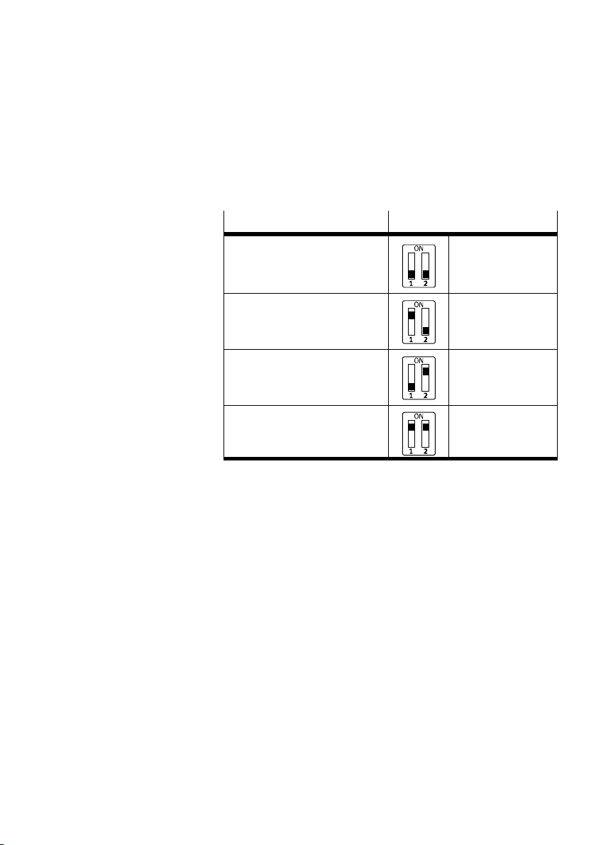
Setting the baud rate with DIL switch 4
You can set the baud rate with 2−element DIL switch 4:
Baud rate
125 kBaud 4.1: OFF
250 kBaud 4.1: ON
500 kBaud 4.1: OFF
1000 kBaud 4.1: ON
Setting DIL switch 4
4.2: OFF
(factory setting)
4.2: OFF
4.2: ON
4.2: ON
Tab.1/8: DIL switch 4 (baud rate)
The following table shows the settings of the DIL switch.
Festo P.BE−CPX−FB14−EN en 0810b
1−17
Page 32
1. Installation
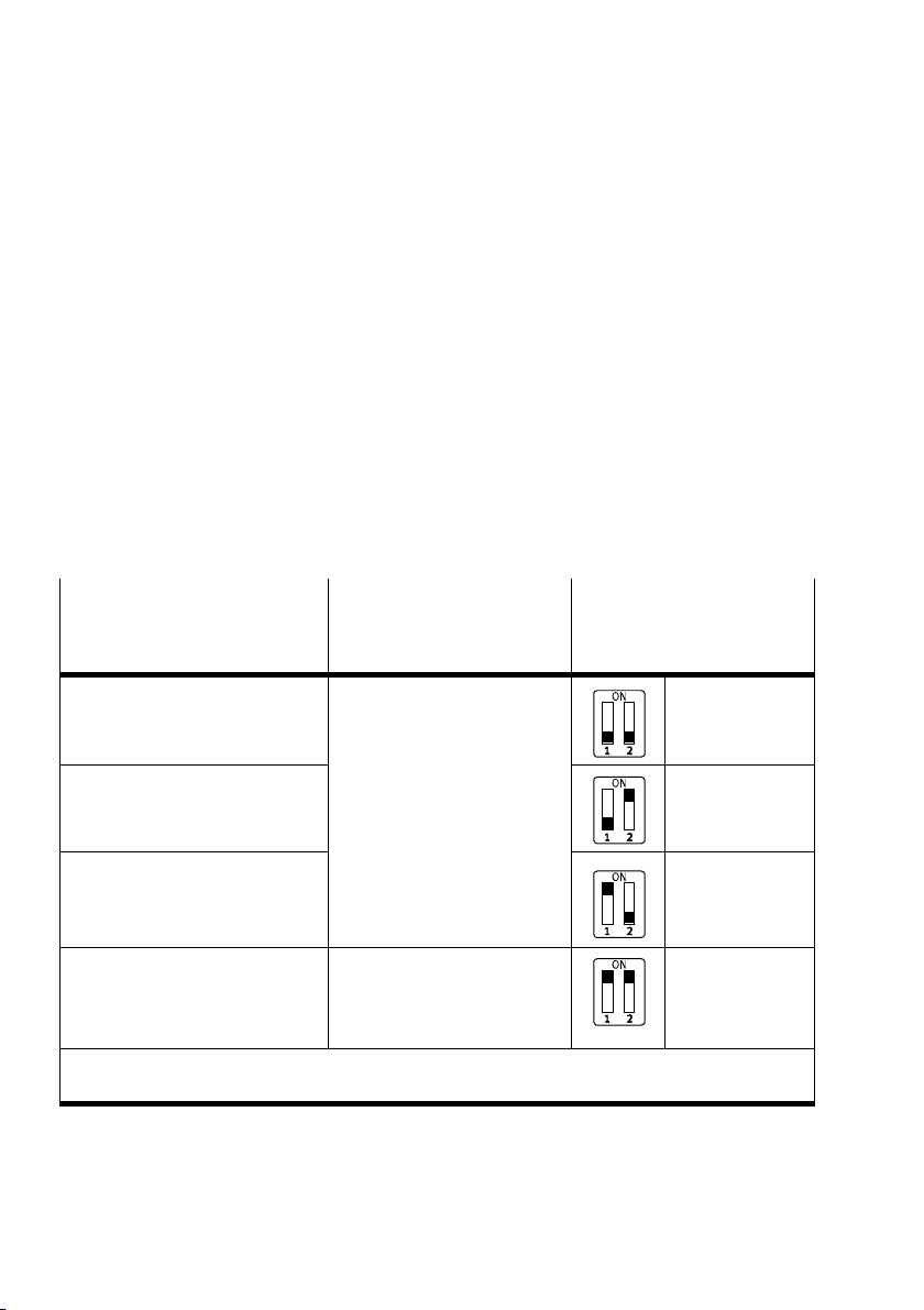
Setting the diagnostic mode or number of logical I/Os with
DIL switch
5
The function of DIL switch 5 depends on the set operating
mode of the CPX terminal (see Tab.1/1):
Operating mode Remote I/O:
Setting the CPX diagnostic mode
The status
bits occupy 8 bits and the I/O diagnostic inter
face 16 bits in PDO 4 (bit 0 Ū 7 or 0 Ū 15, see Fig.2/1).
Remote controller operating mode:
64 I/Os are provided for
communication of the field bus
node with the FEC in PDO 1 (see Fig.2/2).
Remote I/O operating mode
Diagnostic mode Number of I/O bytes
The I/O diagnostic interface and
the status bits are switched off
(+ 0 I/O bits)
The status bits are switched on
(+ 8 (16) I bits)
The I/O diagnostic interface is
switched on
(+ 16 I/O bits)
Reserved for future extensions 8 bytes I/8 bytes O
1)
The diagnosis mode (status bits or I/O diagnosis interface) occupies 2 bytes or 4 bytes of address
space (16 I bits or 16 I/O bits; 8I bits remain unused in the status bits mode)
1)
Remote controller
operating mode
Setting not permitted 3.1: OFF
1)
for communication between
the field bus node and the
CPX−FEC
Setting
DIL switch 5
3.2: OFF
(factory setting)
3.1: OFF
3.2: ON
3.1: ON
3.2: OFF
3.1: ON
3.2: ON
Tab.1/9: DIL switch 5 (diagnosis mode or number of I/O bytes with remote controller)
1−18
Festo P.BE−CPX−FB14−EN en 0810b
Page 33

1. Installation
Note
(1) An activated diagnosis mode reduces the available
address space in the PDO 4.
Use of the diagnostic mode (status bits or I/O diagnostic
interface) occupies 16 I or 16 I/O
bits in the PDO 4. In
combination with technology modules, the number of I/O
bits available for module communication is thus reduced.
In this way, the number of addressable modules is
reduced
in favour of additional status or diagnostic information.
Take account of this fact for the planning of your
CPXterminal.
(2) Later activation of the diagnosis mod
e requires
reconfiguration.
During later activation of the diagnosis module (status bits
or I/O diagnosis interface), the CPX−internal I/O image can
be displaced. Restart the CPX terminal with Power
OFF/ON.
Festo P.BE−CPX−FB14−EN en 0810b
1−19
Page 34
1. Installation
1.3 Connecting the field bus
1.3.1 Field bus cable
Note
Faulty installations or high transmission rates may cause
data transmission errors as a result of signal reflections
and attenuations.
Transmission errors can be caused by:
missing or
incorrect screened connection.
branches
transmission over long distances
unsuitable cables.
Observe the cable specifications. Refer to the manual
your control system for information on the type of cable to
be used.
incorrect terminating resistor.
for
1−20
Use a twisted, screened 4−wire cable as field bus line. The
CANopen bus interface
power via the field bus cable.
If the Festo field bus plug is used, a cable diameter of 5Ū8
or 7Ū10 mm is
Note
If the CPX terminal is fitted onto the moving part of a
machine, the field bus cable on the moving part must be
provided with strain relief. Please also observe the relevant
regulatio
ns in EN60204 part 1.
of the CPX terminal is supplied with
permitted.
Festo P.BE−CPX−FB14−EN en 0810b
Page 35
1. Installation
1.3.2 Field bus baud rate and field bus length
The maximum permissible field bus length and length of the
branch lines depends on the baud rate used. Detailed specifi
cations can be found in the manuals for the
system or bus interface.
Note
· Refer to the manuals for your control system or bus
interface in order to ascertain which T−adapter and
maximum branch line length are permitted for your
controller.
· Also take into account the sum of the branch line lengths
when calculating the maximum permitted length of the
field bus cable.
your control
Festo P.BE−CPX−FB14−EN en 0810b
1−21
Page 36
1. Installation
1.3.3 Information on connecting the field bus
Bus power supply Avoid long distances between the bus interface supply and
the CPX terminal.
Caution
· Make sure the polarity is correct when you connect the
field bus interface and the power supply for the bus
interface/internal logics.
· Protect the power supply for the bus interface with an
external fuse, in accordance with the number of bus
slaves.
· Connect the screen.
Note
Power supply is needed over the field bus cable (pin3and
pin 9 on the Sub−D plug).
Bus slaves have different tolerances in respect of the
interface power supply, depend
Observe this when planning the bus length and placing the
power supply unit.
ing on the manufacturer.
1−22
The following tolerance in the bus interface power supply
(pin3/pin 9 on the sub−D
V
= 30.0 V
max
V
= 11.0 V
min
plug) applies to the CPX terminal:
Recommendation:
Place the power supply unit approximately at the centre of
the bus.
Festo P.BE−CPX−FB14−EN en 0810b
Page 37
1. Installation
6
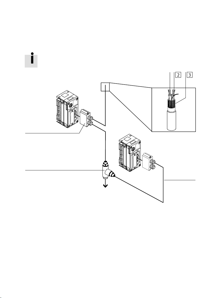
You can implement a T−adapter with the Festo field bus plug
(see fig.).
231
5
1 Field bus
2 Power supply
3 Screening
Fig.1/5: Layout of the bus interface and example of connection
Festo P.BE−CPX−FB14−EN en 0810b
4 Branch line
5 T−adapter (T−Tap)
6 Field bus plug with T−adapter function
4
1−23
Page 38
1. Installation
1.3.4 Field bus interface
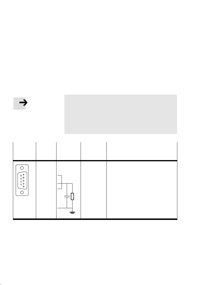
There is 9−pin sub−D plug on the field bus node for connecting
the CPX terminal to the field bus. This connection is used for
the incoming and continuing field
connect the CPX terminal with the field bus plug from Festo
type FBS−SUB−9−BU−2x5POL−B.
bus cables. You can
Note
Note that only the Festo field bus plug guarantees
compliance with protection class IP65.
Before using field bus plugs from other manufacturers:
· Replace the two flat screws with bolts
(typeUNC4−40/M3x6).
Plug on
the CPX
Pin Internal
contacts
CANopen Designation
terminal
1
2
3
4
96
5
51
6
7
8
9
Housing
(plug)
FE
n.c.
CAN_L
CAN_GND
n.c.
CAN_SHLD
GND
CAN_H
n.c.
CAN_V+
Not connected
CAN Bus Low
Power supply to bus (0 V)
Not connected
Connection to functional earth
(screening/shield)
Optional GND
CAN Bus High
Not connected
Power supply to bus (24 V)
Tab.1/10: Pin assignment of the field bus interfaceof the CPX field bus node
1−24
Festo P.BE−CPX−FB14−EN en 0810b
Page 39
1. Installation
1.3.5 Connecting with the field bus plug from Festo
Note
Use protective caps or blanking plugs to seal unused
connections. You will then comply with protection class
IP65.
· Observe the fitting instructions for the field bus plug.
Tighten the two fastening screws at first by hand and then
with max. 0.4 Nm.
You can connect the CPX valve terminal easily to the fiel
d bus
with the field bus plug from Festo (FBS−SUB−9−BU−2x5POL−B).
You can disconnect the plug from the node without inter
rupting the bus cable (T−Tap functio
n).
Note
The clamp strap in the Festo field bus plug is connected
only capacitively internally with the metal housing of the
sub−D plug. This prevents equalizing currents from flowing
via the
screening of the field bus cable (Fig.1/6).
· Clamp the screen of the field bus cable under the clamp
strap in the field bus plug.
Festo P.BE−CPX−FB14−EN en 0810b
1−25
Page 40
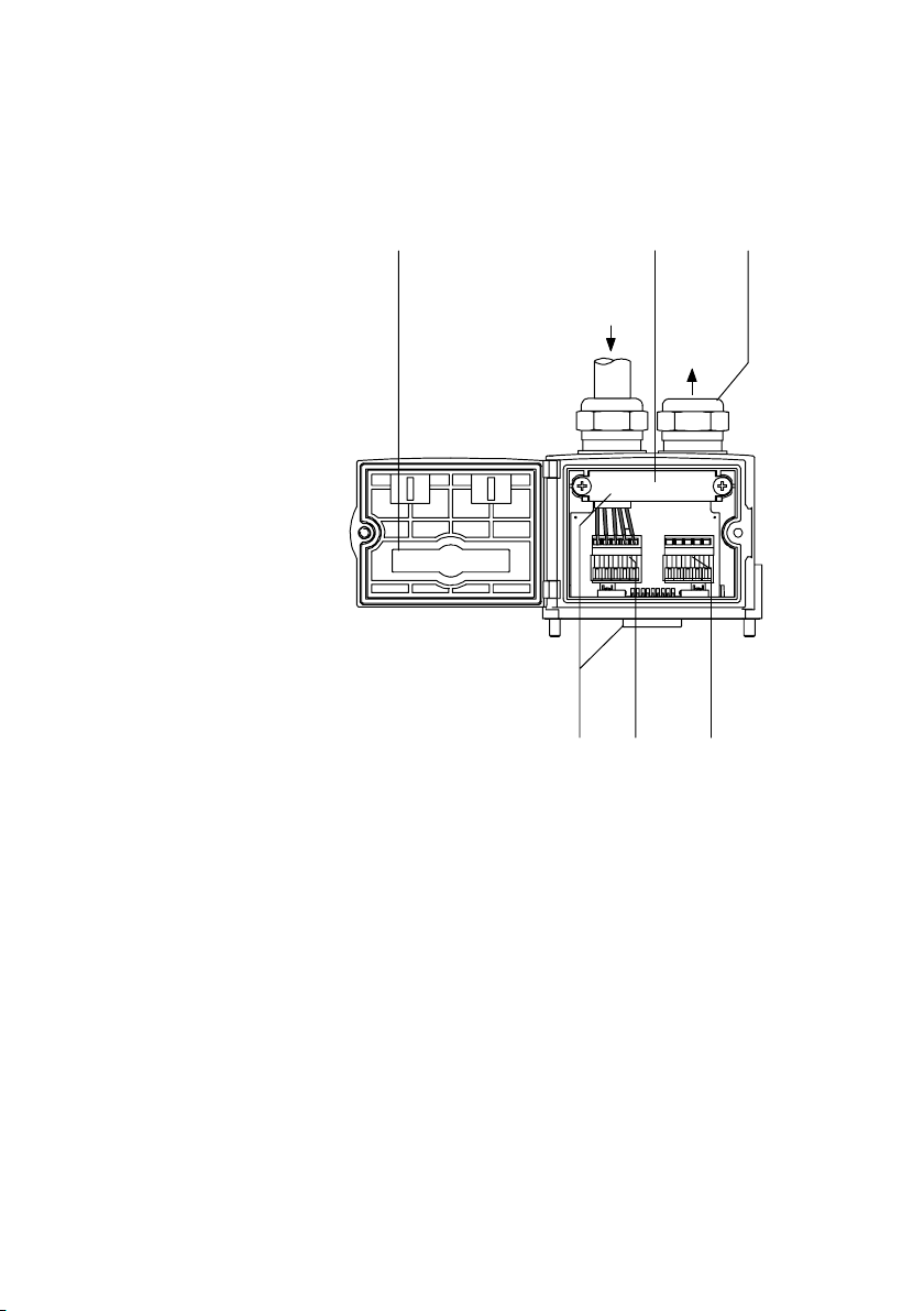
1. Installation
1 Folding cover
with inspection
window
2 Clamp strap for
screen
connection
3 Protective cap if
connection is not
used
4 Field bus
continuing (OUT)
5 Field bus
incoming (IN)
6 Only capacitively
connected
Fig.1/6: Festo field bus plug type FBS−SUB−9−BU−2x5−POL−B
21
Bus IN
GND
V+
H
L
56
SLD
Bus OUT
GND
SLD
V+
H
L
3
4
1−26
Festo P.BE−CPX−FB14−EN en 0810b
Page 41
1. Installation
1.3.6 Further connection possibilities for the field bus with adapters
Caution
· When connecting the field bus interface and the power
supply for the bus interface pay attention to the polarity.
· Connect the screen.
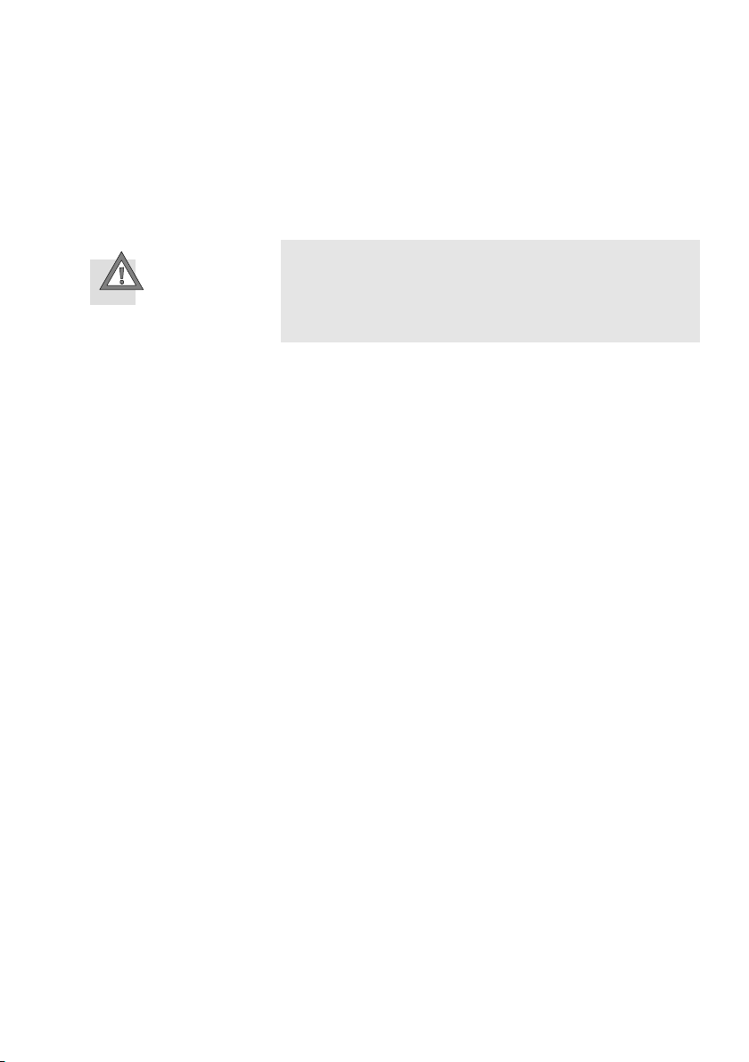
There are further possibilities of connecting the CPX terminal
with adapters which can be ordered separately from Festo.
M12 adapter 5−pin
(protectio
Type FBA−2−M12−5POL
Screw terminal adapter 5−pin
(protection class IP20)
Type FBA−1−SL−5POL
n class IP65)
Festo P.BE−CPX−FB14−EN en 0810b
1−27
Page 42
1. Installation
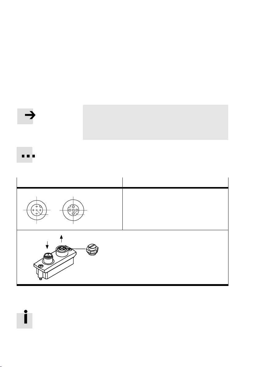
M12 adapter (IP65)
With this adapter the bus is connected via a 5−pin M12 socket
with PG9 screw connector. Use the second connection socket
for the continuation of the field bus.
Note
· Use protective caps or blanking plugs to seal unused
connections.
You will then comply with protection class IP65.
Order this connection at Festo (FBA−2−M12−5POL).
M12
adapter Pin no.
2
3
Bus IN
151
5
4
2
4
Bus OUT
1. Screening
2. 24 V DC bus (max. 4A)
3
Protective cap or plug with bus termination
resistor if connection is not used.
3. 0 V bus
4. CAN_H
5. CAN_L
Fig.1/7: Pin assignment of field bus interface (adapter for 5−pin M12 connection)
With the two M12 connections you can implement a T−adapter
(see Fig.1/5).
1−28
Festo P.BE−CPX−FB14−EN en 0810b
Page 43
1. Installation
Screw terminal adapter (IP20)
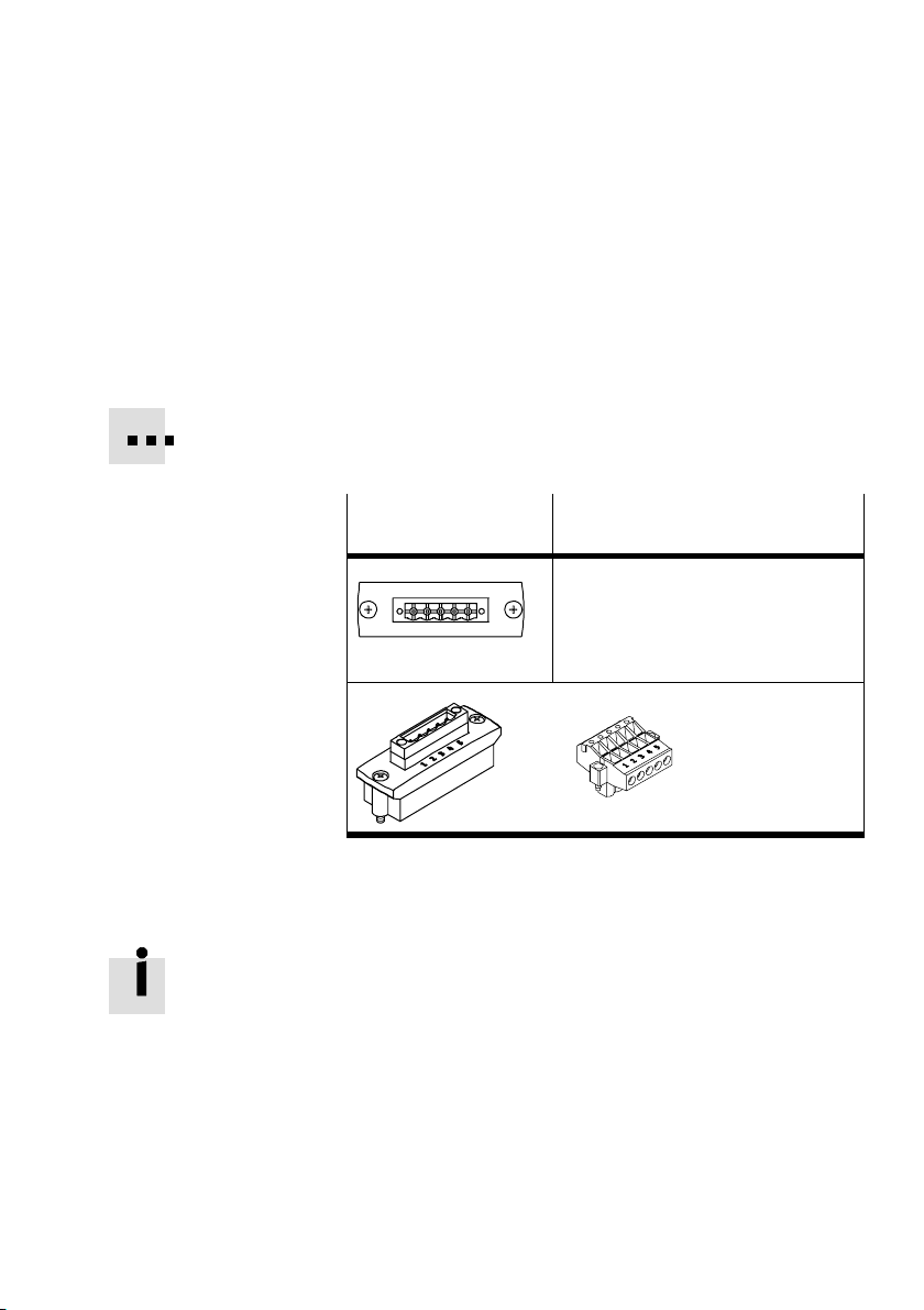
With this adapter the bus is connected to a 2x5−pin terminal
strip. Use the second row of connections for the continuing
field bus.
The maximum permitted current at the
Use cables with a cross sectional area of min. 0.34mm
Order this connection from Festo (FBA−1−SL−5POL) together
with the terminal strip type FBSD−KL−2x5POL.
terminals is 4A.
2
.
Screw terminal
Pin no.
adapter
1. 0 V bus
2. CAN_L
12 345
3. Screening
4. CAN_H
5. 24 V DC bus (max. 4 A)
2x5−pin terminal strip
Fig.1/8: Pin allocation for field bus interface
(5−pin screw terminal adapter)
If you connect the field bus via the terminal strip
FBSD−KL−2x5POL from Festo, you can imp
lement a T−adapter
function.
Festo P.BE−CPX−FB14−EN en 0810b
1−29
Page 44
1. Installation
1.4 Bus terminal with terminating resistors
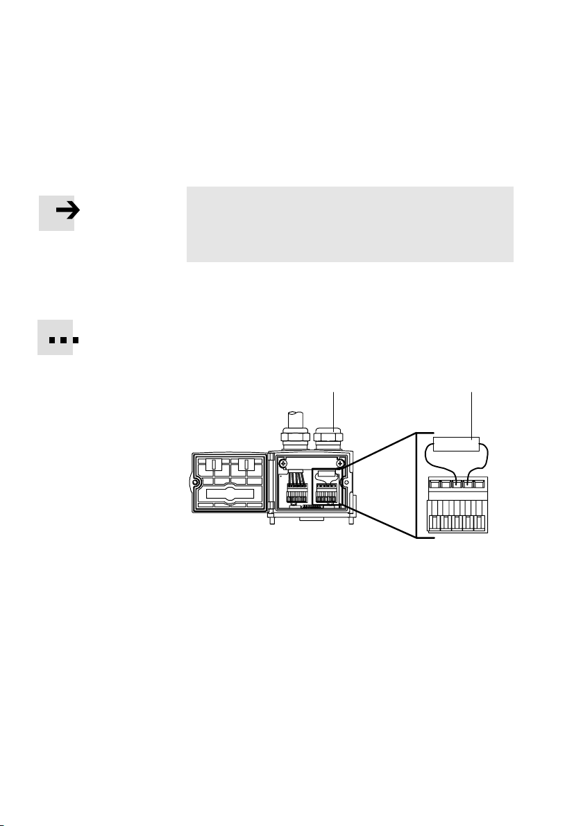
Note
Always use a bus termination at both ends of the field bus.
This also applies if the CPX terminal is at the end of the
field bus.
If you are using T−adapters, install
the terminating resistor at
the unused output of the T−adapter.
Recommendation:
For bus termination, fit a resistor (120 , 0.25 W,
see following diagram) in the Festo field bus
1 Protective cover
12
2 Resistor for bus
termination
(120 , 0.25 W)
GND
GND
SLD
SLD
V+
V+
H
L
H
L
Fig.1/9: Bus termination with resistor in Festo field bus plug
1.4.1 Install a terminating resistor using the adapters
If the CPX terminal to be connected is at the end of the field
bus, a terminating resistor (120 , 0.25 W) must be fitted in
the field bus socket.
plug.
V+
GND
SLD
H
L
1−30
· Connect the terminating resistor between the cores for
CAN_H and CAN_L.
Festo P.BE−CPX−FB14−EN en 0810b
Page 45
1. Installation
1.5 Pin assignment of power supply
Warning
· For the power supply, use only PELV circuits as per
IEC/DIN EN60204−1 (Protective Extra−Low Voltage,
PELV).
Take into account also the general requirements for
PELV circuits as per IEC/DINEN60204−1.
· Use only power sources that guarantee reliable
electrical isolation of the operating voltage as per
IEC/DINEN60204−1.
Through the use of PELV circuits, protection against electric
shock (protection against direct and indirect contact) is
ensured in accordance with IEC/DINEN60204−1 (electrical
equipment of machines, general requirements).
Festo P.BE−CPX−FB14−EN en 0810b
The current consumption of a CPX
terminal depends on the
number and type of integrated modules and components.
Read the information on power supply as well as on the
earthing measures to be carried out in the CPX system
manual.
1−31
Page 46
1. Installation
1)
)
System power supply,
additional power supply
and valve power supply
Plugs
(top view
of device)
7/8"−4POL
C
B
7/8"−5POL
2
3
4
M18
1
4
Push−pull
1
5
2
Interlinking block with
System supply
Type CPX−(M−)GE−EV−S...
A: 24V
B: 24V
D
C: FE
D:0V
A
1: 0V
2: 0V
3: FE
4: 24V
5: 24V
1: 24V
2: 24V
3: 0V
2
3
4: FE
1: 24V
2: 0V
3: 24V
4: 0V
5: FE
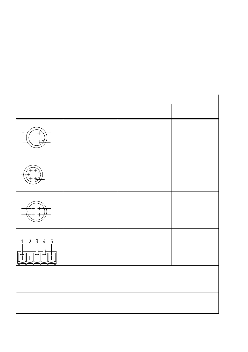
The CPX terminal is supplied with operating and load power
via the interlinking block with system, additional and valve
power supply. Further interlinking blocks are in preparation.
0V
0V
el/sen
val
el/sen
/ 0V
val
/ 0V
val
el/sen
el/sen
val
el/sen
val
el/sen
/ 0V
val
el/sen
el/sen
val
/ 0V
val
/ 24V
/
out
out
/ 24V
/ 24V
/
out
/ 24V
out
out
out
out
out
Additional power supply
Type CPX−(M−)GE−EV−Z...
A: not connected
B: 24V
out
C: FE
D:0V
out
1: 0V
out
2: not connected
3: FE
4: not connected
5: 24V
out
1: not connected
2: 24V
out
3: 0V
out
4: FE
1: not connected
2: not connected
3: 24V
out
4: 0V
out
5: FE
Valve supply
Type CPX−GE−EV−V...
A: not connected
B: 24V
val
C: FE
D:0V
val
1: not connected
2: 24V
val
3: 0V
val
4: FE
V
: Operating voltage for electronics/sensors
el/sen
V
: Load voltage for outputs
out
V
: Load voltage for valves
val
FE: Functional earth
1)
Note the specifications on the plug.
2) Interlinking blocks with forwarding function and interlinking blocks with system supply are
identically constructed.
Tab.1/11: Pin assignment for system supply, additional supply and valve supply
1−32
Festo P.BE−CPX−FB14−EN en 0810b
Page 47

Commissioning
Chapter 2
2−1Festo P.BE−CPX−FB14−EN en 0810b
Page 48

2. Commissioning
Contents
2. Commissioning 2−1 . . . . . . . . . . . . . . . . . . . . . . . . . . . . . . . . . . . . . . . . . . . . . . . .
2.1 Commissioning on a CANopen master 2−3 . . . . . . . . . . . . . . . . . . . . . . . . . . . . . .
2.1.1 General information on CANopen 2−4 . . . . . . . . .
2.2 Configuration 2−5 . . . . . . . . . . . . . . . . . . . . . . . . . . . . . . .
2.2.1 Addressing the CPX terminal 2−5 . . . . . . . . . . . . . . . . . . . . . . . . . . . .
2.2.2 Configuration examples 2−8 . . . . . . . . . . . . . . . . . . . . . . . . . . . . . . . . . .
2.3 Overview 2−14 . . . . . . . . . . .
2.3.1 Brief overview of the scope of functions 2−14 .
2.3.2 Overview Object directory 2−15 . . . . . . . . . . . . . . . . . . . . . . . . . . .
2.3.3 Reaction of the CPX terminal when it is switched on 2−16 . . . . . . . . . . . .
2.3.4 Default identifier distribution 2−18 . . . . . . . . . . . . . . . . . . . . .
2.4 Object directories 2−20 . . . . . . . . . . . . . . . . . . . . . . . . . . . . . . . . . . . . . . .
2.4.1 Communication profile 2−20 . . . . . . . . . . . . . . . . . . . . . . . . . . . . . . . . . . .
2.4.2 Overview of the PDO structure 2−25 .
2.4.3 Digital inputs (transmit PDO 1) 2−26 . . . . . . . . . . . . . . . . .
2.4.4 Digital outputs (receive PDO 1) 2−28 . . . . . . . . . . . . . . . . . . . . . . . . . . . .
2.4.5 Analogue inputs channel 0 Ū 3
2.4.6 Analogue outputs channel 0 Ū 3 (Receive PDO 2) 2−38 . . . . . . . . . . . . .
2.4.7 Analogue inputs channel 4 Ū 15 (Transmit PDO 3) 2−40 . .
2.4.8 Analogue outputs channel 4 Ū 15 (Receive PDO 3) 2−43 . . . . . . . . . . . .
2.4.9 Technology modules, status bits, I/O diagnostic interface
(PDO 4) 2−45 . . . . . . . . . .
2.4.10 Manufacturer specific profile 2−49 . . . . . . . . .
2.4.11 Overview of mappingobjects 2−56 . . . . . . . . . . . . . . . . . . . . . . . . . . .
2.4.12 Force 2−58 . . . . . . . . . . . . . . . . . . . . . . . . . . . . . . . . . . . . . . . . . . . . . .
2.4.13 Function assignment and virtual modules 2−62 . . . . . . . . . . . . . . . . . . . .
2.5 Parameterizing 2−68 . . . . . . . . . . . . . . . . . . . . .
2.5.1 Parameterizing when switching on 2−68 . . . . . . . . . . . . . . . . . .
2.5.2 Parameterization with the handheld 2−69 . . . . . . . . . . . . . . . . . . . . . . . .
2.5.3 Application example for parameterization 2−69 . . . . . . . . . . .
2.6 Commissioning the CPX terminal in the system 2−70 . . . . . . . . . . . . . . . . . . . . . . .
2.6.1 Error−free commissioning, normal operating status 2−70 . . . . . .
. . . . . . . . . . . . . . . . . . . . . . . . . . . . . . . . . . . . . . . . . . .
. . . . . . . . . . . . . . . . . . . . . . . . . . . .
(transmit PDO 2) 2−33 . . . . . . . . . . . . . .
. . . . . . . . . . . . . . . . . . . . . . . . . . . . . . . . . . . . . .
. . . . . . . . . . . . . . . . . . . . . . . . . . . .
. . . . . . . . . . . . . . . . . .
. . . . . . . . . . . . . . . . . . .
. .
. . . . . . . . . . . . . . . . . . . .
. . . . .
. . . . . . . . .
. . . . . . . .
. . . . . . . . . . . .
. . . . . . . . . . .
. . . . . . . . . . . . . . . . . . . . .
. . .
. . . .
. . . . . . . .
. . . . . . . . .
. . . . . .
2−2
Festo P.BE−CPX−FB14−EN en 0810b
Page 49
2. Commissioning
2.1 Commissioning on a CANopen master
This section describes the configuration and addressing of a
CPX valve terminal on a CANopen interface or CANopen
master.
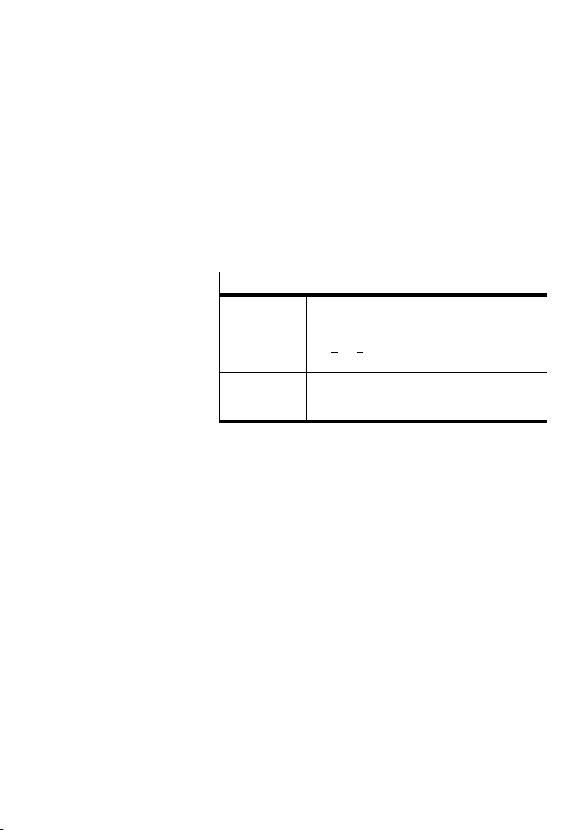
The following specifications have been taken into account:
CANopen specifications
DS201
DS207
DS301, V4.01 The Draft Standard 301 is based on the CAL
DS401, V2.0 The Draft Standard 401 defines the device
CAN Application Layer CAL
communication profile
profiles for input and output modules within
CANopen
Tab.2/1: CANopen specifications taken into account with
the CPX terminal
In order to understand this chapter, you should be familiar
with C ANopen and the specifications DS301 and DS401.
Festo P.BE−CPX−FB14−EN en 0810b
2−3
Page 50

2. Commissioning
2.1.1 General information on CANopen
CANopen devices have an object directory which makes all
important slave parameters accessible in a standardized
manner. A CANopen system is configured mainly by access to
the object directory of the individual slaves. The access
mechanism is provided by Service Data Objects (SDOs).
There are two different communication mechanisms in a
CANopen system.
Process Data Objects (PDOs) provide fast transfer of
The
processing data and are transmitted by simple CAN
messages without protocol overhead. Process Data Objects
can be transmitted event−controlled, synchronous to a system
pulse sequence or on demand.
ervice Data Objects (SDO) form a point−to−point
The S
connection and permit access to every entry in the object
directory of a node.
2−4
Festo P.BE−CPX−FB14−EN en 0810b
Page 51
2. Commissioning
2.2 Configuration
2.2.1 Addressing the CPX terminal
Before configuring, ascertain the exact number of available
inputs/outputs. Depending on what you have ordered, a CPX
terminal comprises a different number of I/Os.
The I/Os will be assigned automatically within the CPX
terminal (standard setting). The following applies to inputs
and outputs:
The address assignment of the inputs does not depend on
outputs.
the
The counting method does not depend on the position of
the field bus node. The field bus node counts as a module
with 0 or 8 inputs or 16 inputs and outputs, depending on
the setting of DIL switch 5 (see section 1.2.2).
Festo P.BE−CPX−FB14−EN en 0810b
Counting is from left to right, in ascending order
gaps.
Note
Note that a CPX terminal provides status bits or an
I/Odiagnostic interface, depending on the setting.
The status bits must be treated like inputs and occupy
8bits in the Transmit PDO 4 (standard setting).
The 16 bits of the I/O diagnostic interface must be
treated like inputs and outputs. They each occupy
16bits
in the Transmit and Receive PDO 4 (standard
setting).
without
2−5
Page 52
2. Commissioning
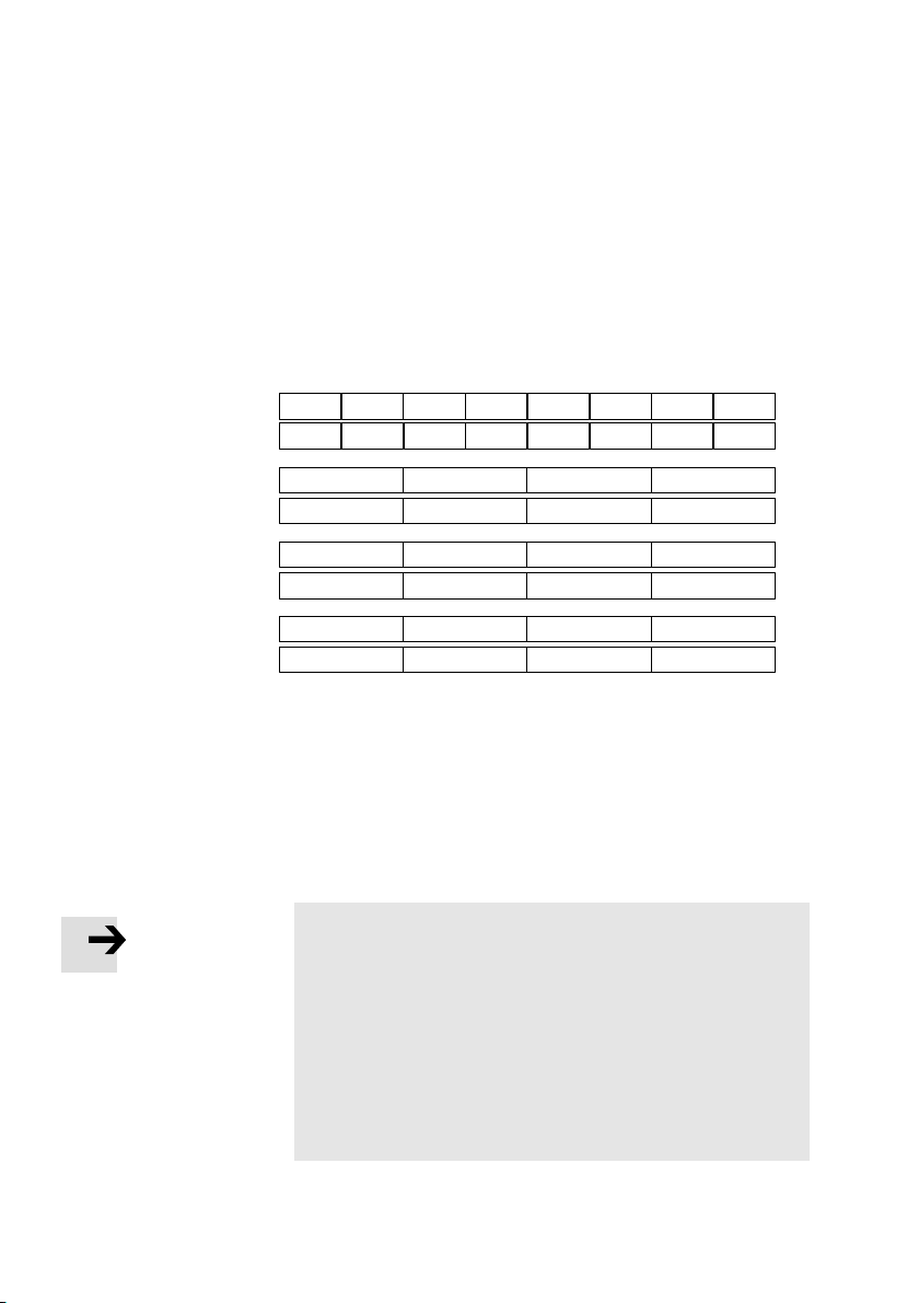
The following diagram shows the standard distribution of
I/Os in the operating mode Remote I/O. If you use more than
8 I/O bytes, you must map these into the PDOs by mapping".
In this case, the use of analogue channels will be limited.
The same applies in the reverse case if more
than 8analogue
channels are mapped into the PDOs by mapping.
Transmit PDO 1
Receive PDO 1
Transmit PDO 2
Receive PDO 2
Transmit PDO 3
Receive PDO 3
Transmit PDO 4
Receive PDO 4
I0ŪI7
O0ŪO7
O8ŪO15 O16ŪO23 O24ŪO31 O32ŪO39 O40ŪO47 O48ŪO55 O56ŪO63
OI0
IW0 / diagnosis
IW0 / IO diag.
1)
Depending on configuration:
with status bits: I0 Ū I7, with I/O diagnostic interface: I0 Ū I15
The input words of the technology modules shift correspondingly.
2)
Depending on configuration:
With activated I/O diagnosin interface O0 Ū O15 (see section 1.2.2)
The output words of the technology modules shift correspondingly.
OI1 OI2 OI3
1)
IW1
2)
I56ŪI63I8ŪI15 I16ŪI23 I24ŪI31 I32ŪI39 I40ŪI47 I48ŪI55
AO3AO2AO1AO0
AI7AI6AI5AI4
AO7AO6AO5AO4
IW3IW2
OW3OW2OW1
Fig.2/1: Overview of PDO 1 Ū 4 and position of the status bits and I/O diagnostic
interface
Note
For the Receive PDO 1 Ū 4:
The necessary telegram length depends on the
equipment fitted on the CPX and is 1 Ū 8 byte.
If the telegram received is shorter than the necessary
telegram length, a fault message will be output.
If the telegram received is longer, the part
corresponding to the
necessary length will be
processed.
2−6
Festo P.BE−CPX−FB14−EN en 0810b
Page 53
2. Commissioning
Remote controller operating mode
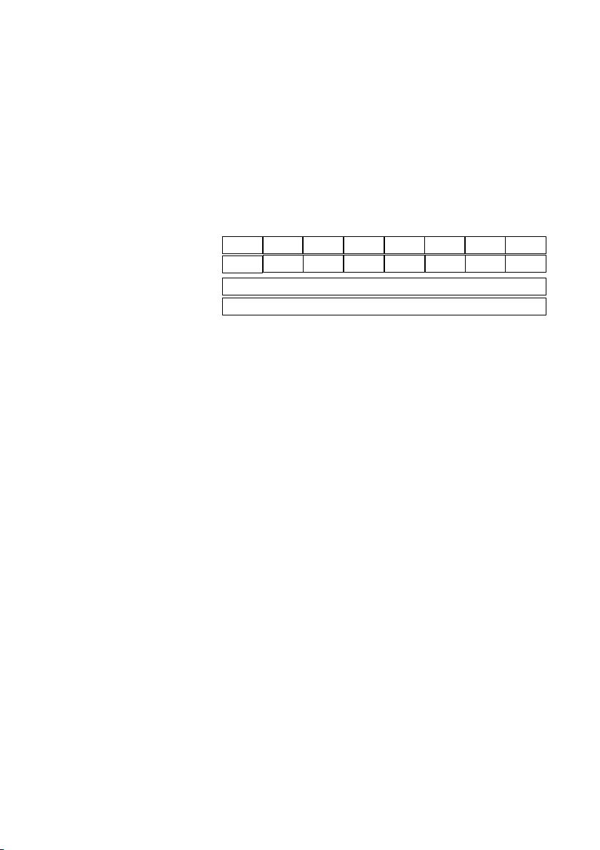
In the Remote Controller operating mode (DIL switch1)
onlythe PDOs 1 are assigned. They contain 64 logical I/Os
for data exchange with the Remote Controller.
Transmit PDO 1
Receive PDO 1
Transmit PDO 2 Ū 4
Receive PDO 2 Ū 4
I0ŪI7 I56ŪI63I8ŪI15 I16ŪI23 I24ŪI31 I32ŪI39 I40ŪI47 I48ŪI55
O0ŪO7
O8ŪO15
O16ŪO23
O24ŪO31
Unused
Unused
O32ŪO39
O40ŪO47 O48ŪO55 O56ŪO63
Fig.2/2: 64 logical I/Os in the PDO 1 in the Remote Controller operating mode
Festo P.BE−CPX−FB14−EN en 0810b
2−7
Page 54
2. Commissioning
2.2.2 Configuration examples
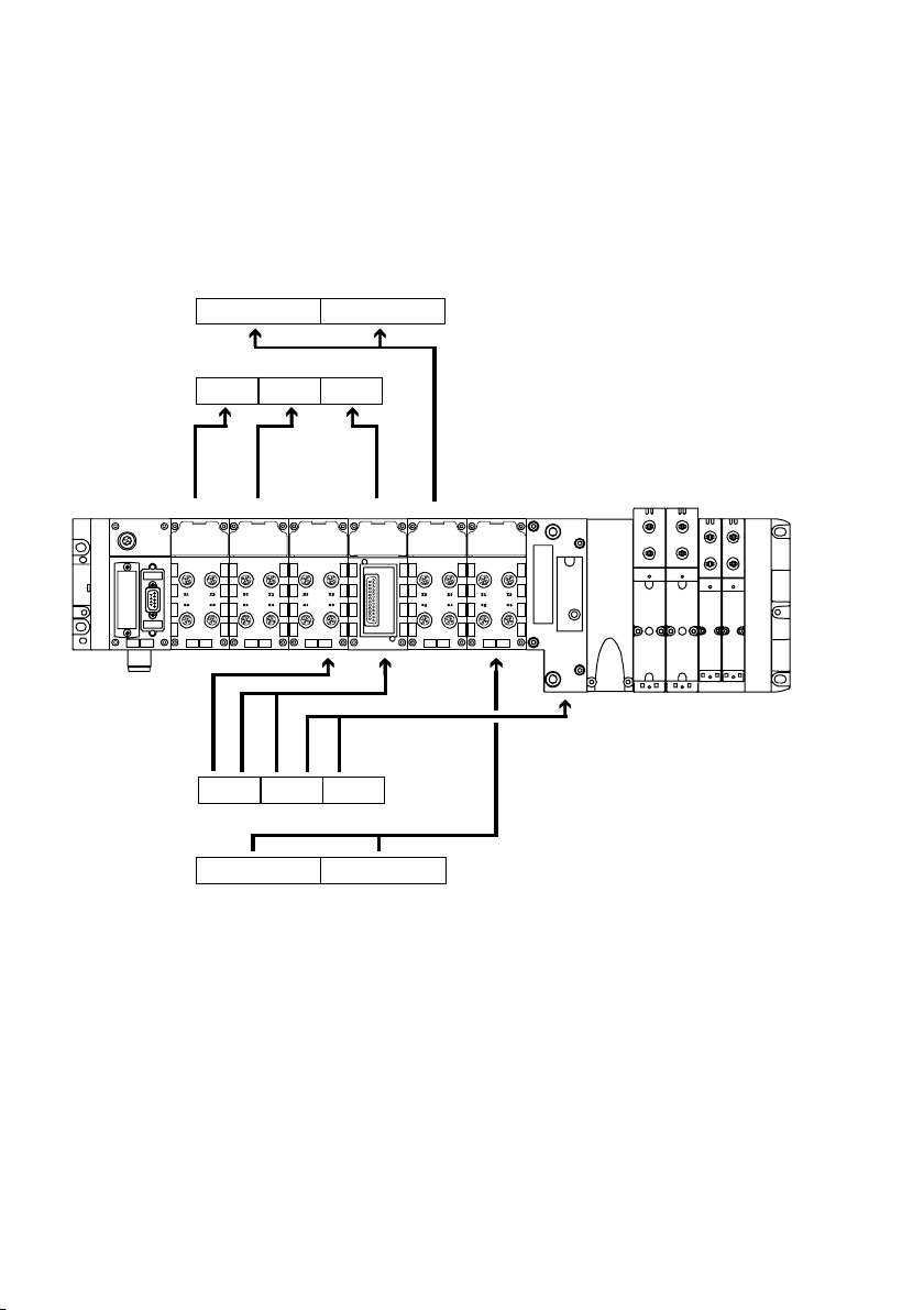
Configuration and addressing example 1
T−PDO4
T−PDO1
Mod. no.:
R−PDO1
R−PDO4
IW0
I0ŪI7 I8ŪI15 I16ŪI23
(I/O diagnostic interface)
012 34
8DI 8DI 8DO8DI 8DO 4DO
O32ŪO39
O0ŪO7 O8ŪO15 O16ŪO23
OW0 (I/O diagnostic interface)
O24ŪO31
5
8O 8O
6
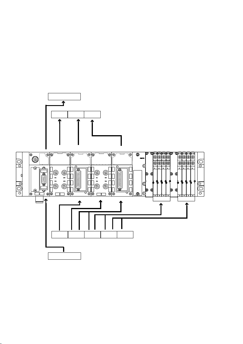
Fig.2/3: Assignment of the PDOs on a CPX terminal with digital I/O modules and
MPApneumatics and activated I/O diagnosis interface
(standard assignment without mapping, configuration see Tab.2/2)
2−8
Festo P.BE−CPX−FB14−EN en 0810b
Page 55
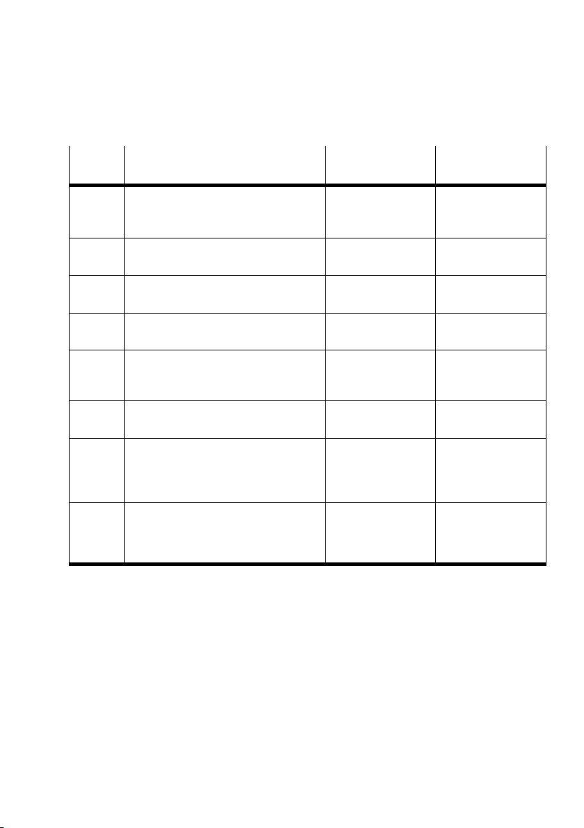
2. Commissioning
Module
Module Input address Output address
no.
0 CANopen field bus node
1 Digital 8−input module
2 Digital multi I/O module
3 Digital 4−output module
4 Digital multi I/O module
MPA pneumatic interface
5 MPA pneumatic module (8DO)
6 MPA pneumatic module (8DO)
CPX−FB14
With activated I/O diagnostic interface
CPX−8DE
CPX−8DE−8DA
CPX−4DA
CPX−8DE−8DA
Passive module
MPA1S: VMPA1−FB−EMS−8
MPA pneumatic modules without
separate power supply circuits
MPA1S: VMPA1−FB−EMS−8
MPA pneumatic modules without
separate power supply circuits
T−PDO 4: IW0
Obj. 6100,1
T−PDO 1: I0 Ū I7
Obj. 6000,1
T−PDO 1: I8 Ū I15
Obj. 6000,2
R−PDO 1: O8 Ū O11
T−PDO 1: I16 Ū I23
Obj. 6000,3
R−PDO 1: O20 Ū O27
R−PDO 1: O28 Ū O35
R−PDO 4: OW0
Obj. 6300,1
R−PDO 1: O0 Ū O7
Obj. 6200,1
Obj. 6200,2
R−PDO 1: O12 Ū O19
Obj. 6200,2
Obj. 6200,3
Obj. 6200,3
Obj. 6200,4
Obj. 6200,4
Obj. 6200,5
Tab.2/2: Configuration for example terminal 1 in Fig.2/3
How to prepare a changed configuration of this example with
assignment function and virtual modules can be found in
section 2.4.13.
Festo P.BE−CPX−FB14−EN en 0810b
2−9
Page 56
2. Commissioning
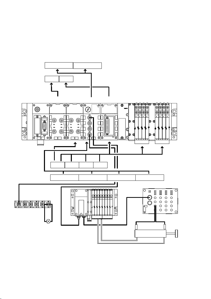
Configuration and addressing example 2
T−PDO2
T−PDO1
Module no.:
R−PDO1
R−PDO2
OI0 OI1
I0ŪI7 I8ŪI15 I16ŪI23
12345
8DI 8DI 4DO 8DI 2AI8DO
O8ŪO15 O16ŪO23
O0ŪO7
AO1AO0
2AO
76
8O
Fig.2/4: Assignment of the PDOs on a CPX terminal with digital and analogue
I/Omodules, VTSA pneumatics (DIL switch setting 8O) and not−activated
diagnostic functions (standard assignment without mapping, configuration
seeTab.2/3)
2−10
Festo P.BE−CPX−FB14−EN en 0810b
Page 57
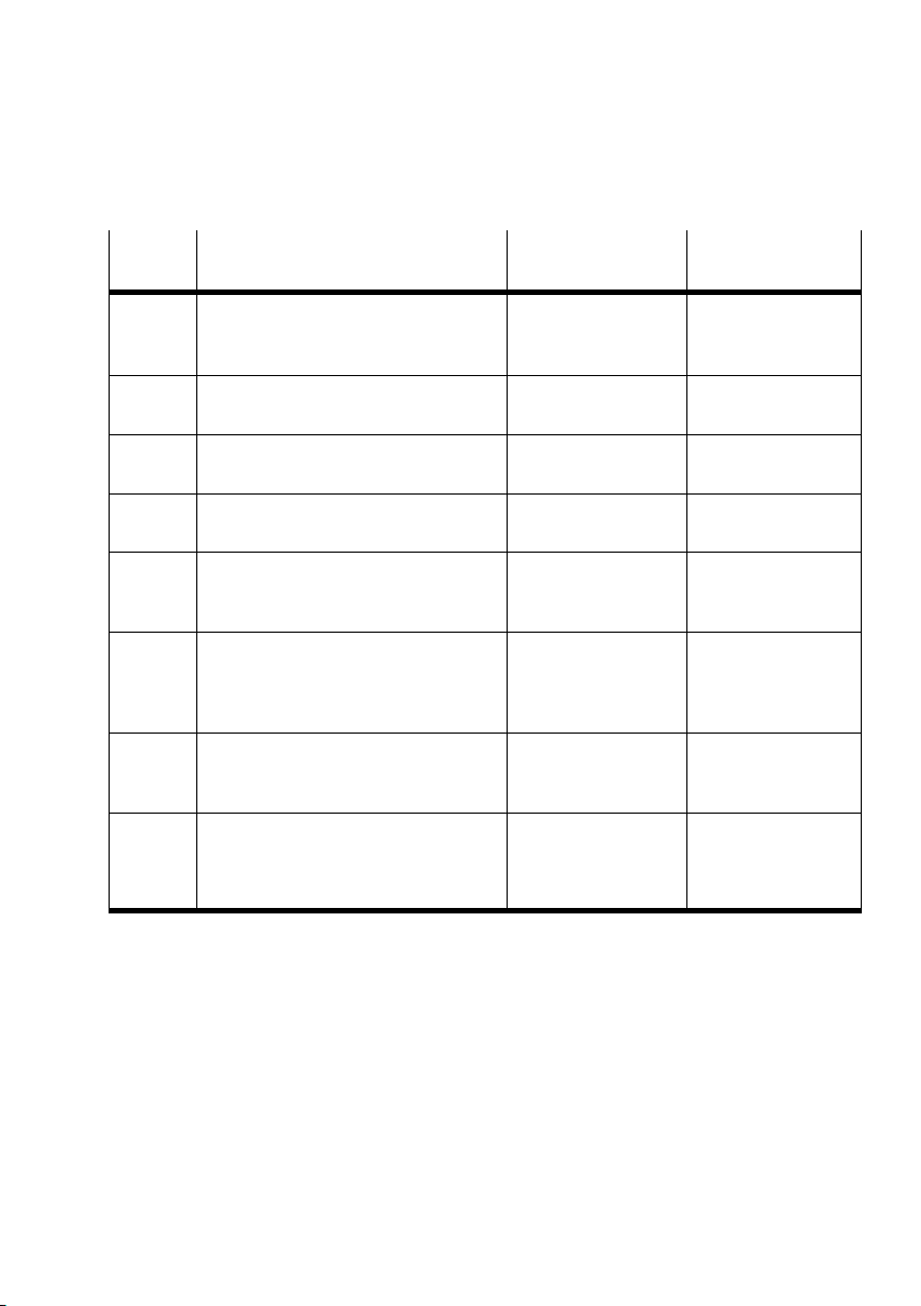
2. Commissioning
Module
Module Input address Output address
no.
0 Field bus node
1 Digital 8−input module
2 Digital 8−input module
3 Digital 4−output module
4 Digital multi I/O module
5 Analogue 2−input module
6 Analogue 2−output module
7 VTSA pneumatic interface
CPX−FB14
Without activation of diagnostic functions
CPX−8DE
CPX−8DE
CPX−4DA
CPX−8DE−8DA
CPX−2AE−U−I
CPX−2AA
ISO Plug−In (type 44)
DIL switch in the interface set to 1Ū8
solenoid coils (8DO)
T−PDO 1: I0 Ū I7
Obj. 6000,1
T−PDO 1: I8 Ū I15
Obj. 6000,2
R−PDO 1: O0 Ū O3
T−PDO 1: I16 Ū I23
Obj. 6000,3
T−PDO 2: AI0 Ū AI1
Obj. 6401,1
Obj. 6401,2
R−PDO 2: AI0 Ū AI1
Obj. 6200,1
R−PDO 1: O4 Ū O11
Obj. 6200,1
Obj. 6200,2
Obj. 6411,1
Obj. 6411,2
R−PDO 1: O12 Ū O19
Obj. 6200,2
Obj. 6200,3
Tab.2/3: Configuration for example terminal 1 in Fig.2/4
Festo P.BE−CPX−FB14−EN en 0810b
2−11
Page 58
2. Commissioning
Configuration and addressing example 3
T−PDO4 IW1
T−PDO1
Module no.: 6
R−PDO1
R−PDO4
String 4, outputs
IW0
I8ŪI15
I0ŪI7
0
123 4 5
8DI 4DO 8DI 8DO
O0ŪO7 O8ŪO15
OW0
O16ŪO23
OW1 OW2 OW3
8 O
O24ŪO31
String 1
8 O
String 1
Fig.2/5: Assignment of the PDOs on a CPX terminal with digital I/O modules, CPX−CP
interface, MPA pneumatics and not−activated diagnostic functions (standard
assignment without mapping, configuration see Tab.2/4)
2−12
Festo P.BE−CPX−FB14−EN en 0810b
Page 59
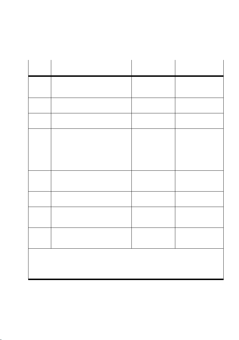
2. Commissioning
Module
Module Input address Output address
no.
0 Field bus node
1 Digital 8−input module
2 Digital 4−output module
3 CPX−CP interface
4 Digital multi I/O module
MPA pneumatic interface
5 MPA pneumatic module (8DO)
CPX−FB14
Without activation of diagnostic functions
CPX−8DE
CPX−4DA
CPX−CP
On string 1, 4 I bytes are assigned (32I)
On string 1Ū4, 16 O bytes are assigned
(128O)
CPX−8DE−8DA
Passive module
MPA1S: VMPA1−FB−EMS−8
MPA pneumatic module
T−PDO 1: I0 Ū I7
Obj. 6000,1
R−PDO 1: O0 Ū O3
T−PDO 4: IW0 Ū IW1
Obj. 6100,1
Obj. 6100,2
T−PDO 1: I8 Ū I15
Obj. 6000,2
R−PDO 1: O12 Ū O19
Obj. 6200,1
R−PDO 4: OW0 Ū OW3
Obj. 6300,1
Obj. 6300,2
Obj. 6300,3
Obj. 6300,4
Manual mapping for
OW4 Ū OW7
R−PDO 1: O4 Ū O11
Obj. 6200,1
Obj. 6200,2
Obj. 6200,2
Obj. 6200,3
1)
6 MPA pneumatic module (8DO)
1)
Manual mapping:
The CPX−CP interface occupies in the configuration 16 byte outputs (128O). Since the PDO 4 can
only address the first 8 bytes (64O), manual mapping is required for configuration of this CPX
terminal. As a result, the remaining output bytes can be made available over other PDOs.
(OW4ŪOW7 are not depicted in Fig.2/5).
MPA1S: VMPA1−FB−EMS−8
MPA pneumatic module
R−PDO 1: O20 Ū O27
Obj. 6200,3
Obj. 6200,4
Tab.2/4: Configuration for example terminal 3 in Fig.2/5
Festo P.BE−CPX−FB14−EN en 0810b
2−13
Page 60

2. Commissioning
2.3 Overview
2.3.1 Brief overview of the scope of functions
Module states and boot−up as per Communication Profile
DS301
1 service data object for read and write access to the
object directory Send and receive SDO
4 process data objects for access to digital and analogue
inputs: Transmit PDO 1 Ū 4
4 process data objects for access to digital and analogue
outputs:
Emergency telegram for fault message to the master
Node guarding and heart beat
Receive PDO 1 Ū 4
2−14
Default setting of all identifiers as per DS301 and the
station number (predefined connection set)
Variable mapping
Function assignment and virtual modules
Festo P.BE−CPX−FB14−EN en 0810b
Page 61
2. Commissioning
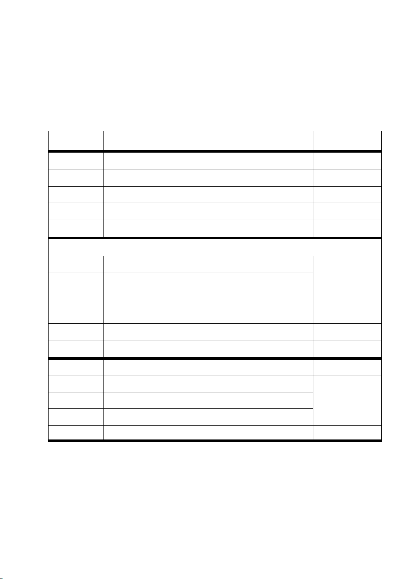
2.3.2 Overview Object directory
Index (hex) Objects See section
1000Ū1200 Communication part of the object directories 2.4.1
1400Ū1403 Communication parameters for receive PDO 1Ū4 2.4.4
1800Ū1803 Communication parameters for Transmit PDO 1Ū4 2.4.3
1600Ū1603 Mapping parameters for Receive PDO 1Ū4 2.4.4
1A00Ū1A03 Mapping parameters for Transmit PDO 1Ū4 2.4.3
Manufacturer specific (2000Ū5FFF):
2000Ū2110 System and module data 2.4.10
2200Ū2210 System and module diagnostic data
2300Ū2310 Diagnostic memory data
2400Ū2421 System and module parameters
4000Ū4801 Function assignment module (virtual modules) 2.4.13
5000Ū5FFF Force tables 2.4.12
6000, 6100 Input array 2.4.3
6200, 6300 Output array 2.4.4
6206/6306 Fault mode array for the outputs
6207/6307 Fault state array for the outputs
64xx Analogue inputs and outputs 2.4.5
Tab.2/5: Implemented objects of the CPX terminal
Festo P.BE−CPX−FB14−EN en 0810b
2−15
Page 62
2. Commissioning
2.3.3 Reaction of the CPX terminal when it is switched on
Power on
Application initialization
00
4
Communication initialization
0
0
Pre−operational
2
1
3
3
Operational
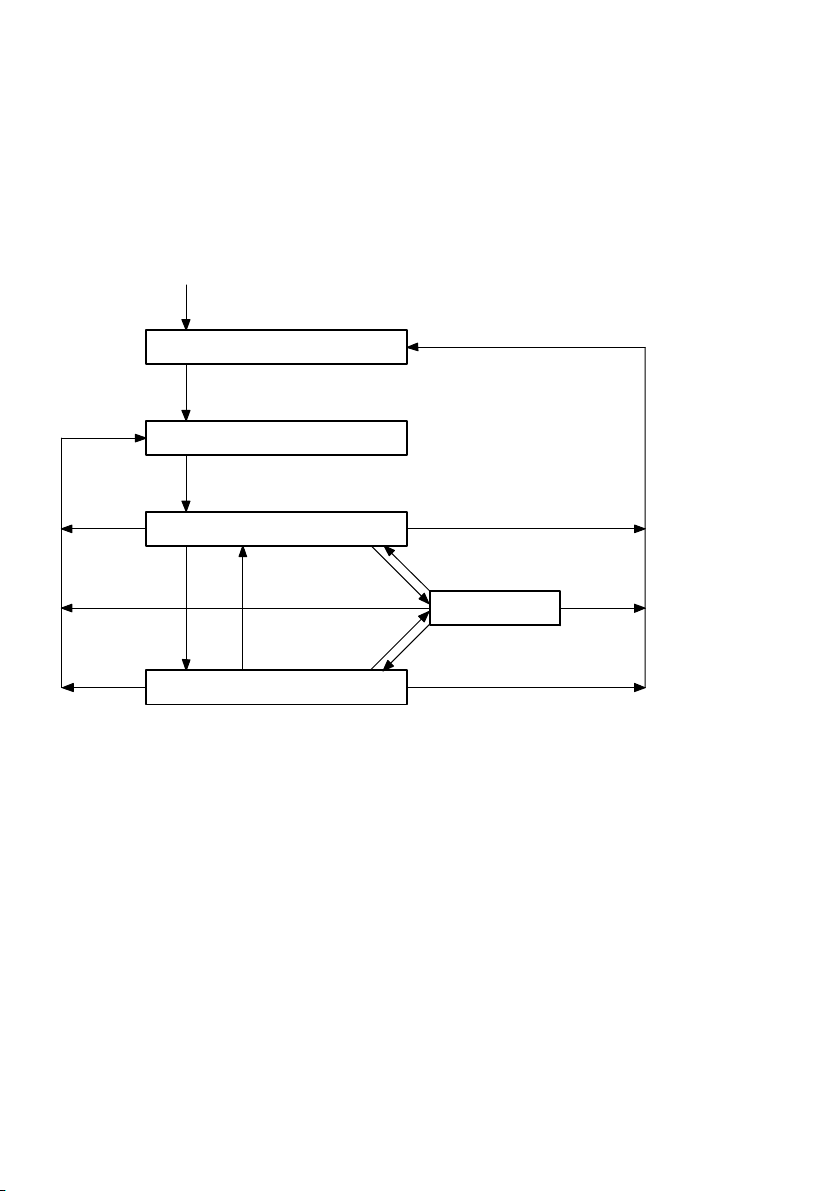
Fig.2/6: Status transitions of the CPX terminal
(see illustration Tab.2/6 on the next page)
5
2
Stopped
1
2−16
Festo P.BE−CPX−FB14−EN en 0810b
Page 63
2. Commissioning
0
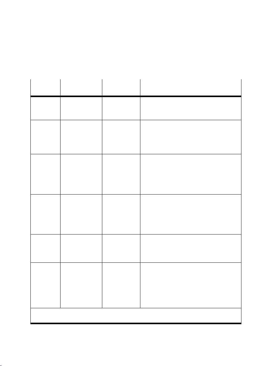
Description of the status transitions
Status
Designation Command
transition
0
1 Start_Remote_
2 Enter_Pre_
3 Stop_Node_
4 Reset_
Automatic boot−up after power on
Node_Indication
Operation_State_
Indication
Indication
Communication_
Indication
specifier (cs)
01
h
80
h
02
h
82
h
Function
The saved parameters 2000Ū5FFF are loaded
only after power on
Starts the CPX terminal in operational mode:
SDO transmission valid
PDO transmission (outputs active)
Node guarding / Heart beat valid
(Node guard response: Toggle + 05h)
CPX terminal in pre−operational mode:
SDO transmission valid
PDO transmission invalid
Outputs assume error status 2))
Node guarding / Heart beat valid
(Node guard response: Toggle + 7Fh)
CPX terminal in Stopped mode:
SDO transmission invalid
PDO transmission invalid
(Outputs assume error status 2))
Node guarding / Heart beat valid
(Node guard response:Toggle + 04h)
Resetting the communication functions:
Outputs are reset
Communication parameters are reset
(objects 1000Ū1FFF)
1)
5 Reset_Node_
Indication
81
h
Module reset including application:
Outputs are reset
Maskings of the outputs are reset to default
Communication parameters are reset
(objects 1000Ū1FFF)
Stored parameters (2000Ū5FFF) are not
reloaded.
1)
The objects 6000Ū are always loaded with the default settings after power−on
2)
Only after the transition from operational mode to stopped or pre−operational mode
Tab.2/6: Status transitions
Festo P.BE−CPX−FB14−EN en 0810b
2−17
Page 64
2. Commissioning
2.3.4 Default identifier distribution
The following table shows the identifier distribution:
Broadcast objects
Object name
SYNC 080
Object designation Value range of the COB identifier on the CPX
Tab.2/7: Broadcast objects
terminal
h
128
d
2−18
Festo P.BE−CPX−FB14−EN en 0810b
Page 65
2. Commissioning
Peer−to−peer objects
Object
EMERGENCY For procedures with high
Object designation Value range of the COB identifier
priority, e.g. undervoltage
081
129dŪ 255
Transmit PDO 1 PDO 1 (tx) 181
385dŪ 511
Receive PDO 1 PDO 1 (rx) 201
513dŪ 639
Transmit PDO 2 PDO 2 (tx) 281
641dŪ 767
Receive PDO 2 PDO 2 (rx) 301
769dŪ 895
Transmit PDO 3 PDO 3 (tx) 381
897dŪ 1023
Receive PDO 3 PDO 3 (rx) 401
1025dŪ 1151
Transmit PDO 4 PDO 4 (tx) 481
1153dŪ 1279
Receive PDO 4 PDO 4 (rx) 501
1281dŪ 1407
Transmit SDO SDO 1 (tx) 581
1409dŪ 1535
Receive SDO SDO 1 (rx) 601
1537dŪ 1663
Node guarding /
Heart beat
Guarding 701h 77F
1793dŪ 1919
0FF
h
h
h
h
h
h
h
h
h
h
h
h
d
1FF
h
d
27F
h
d
2FF
h
d
37F
h
d
3FF
h
d
47F
h
d
4FF
h
d
57F
h
d
5FF
h
d
67F
h
d
h
d
Tab.2/8: Peer to Peer objects of the CPX−FB14
Festo P.BE−CPX−FB14−EN en 0810b
2−19
Page 66
2. Commissioning
2.4Object directories
2.4.1 Communication profile
The following tables show the objects of the communication
part (values and examples: module ID = 1).
In the following: U = unsigned
Note
For mapping the rules as per CiA DS301 apply: Mapping
entries are only possible if the number of parameters has
previously been set to zero.
(Example: index 1A00, subindex 3 Ū 8:
After entering the mapping values, set the number of
parameters to the appropriate value again.
ro = read only
rw = read/write
Map. = mapping possible
Attr. = attribute
Set subindex 0 to 0").
2−20
Festo P.BE−CPX−FB14−EN en 0810b
Page 67
2. Commissioning
Index
(hex)
1000 0 Device type U32 ro 00 0F 91 01 As from software status
1001 0 Error
1001 0 Error
1002 0 Manufac
Sub
index
Designa
tion
register
turer status
register
Type Attr. Map. Values
Explanation
(hex)
V1.10:
OF = maximum amount of
equipment on the CPX
terminal
00 0x 91 01 Prior to software status
Example:
00 03 91 01
U8 ro Yes 00 no error
U8 ro Yes xx Generic/manufacturer error
U32 ro Yes 00 00 00 00 Module number and fault
V1.10:
91 01 = device profile
x = depends on equipment
fitted on the CPX terminal:
Bit 16: digital inputs
Bit 17: digital outputs
Bit 18: analogue inputs
Bit 19: analogue outputs
CPX terminal with digital
inputs and outputs
(see section 3.5.1)
number
(see section 3.5.1)
Festo P.BE−CPX−FB14−EN en 0810b
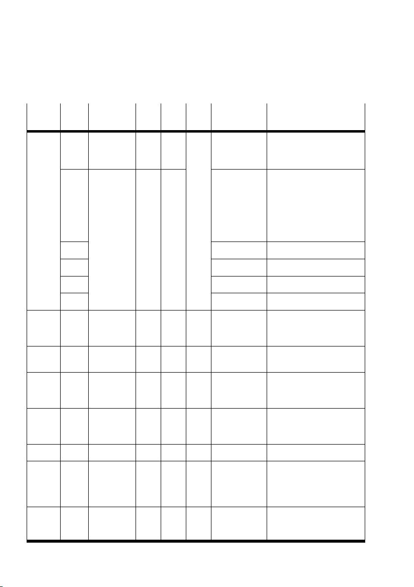
2−21
Page 68
2. Commissioning
Index
(hex)
1003 0 Pre−defined
1005 0 COB−ID
1008 0 Manufact.
1009 0 Manufact.
Sub
tion
index
error field
1 Standard
error field
2 xx xx xx xx Error (n+1)
3 xx xx xx xx Error (n+2)
... ... ...
A
h
SYNC
message
device name
hardware
version
Map.Attr.TypeDesigna
ExplanationValues
(hex)
U8 rw 00 Ū 0A Number of current errors
U32 ro xx xx xx xx Most recent error (n)
xx xx xx xx Oldest error n+9
U32 rw 80 Default SYNC message
Str. ro FB14" Node designation
Str. ro 0810"
(example)
(Write 00 deletes all errors)
(see section 3.5.1)
Byte 0 Ū 1 = error code
(see section 3.5.1)
Byte 2 = byte 0 of
index 1002
Byte 3 = byte 1 of
index 1002
COB−ID 80
Current hardware status
h
100A 0 Manufact.
software
version
100C 0 Guard time U16 rw 00 00 Timeout monitoring [ms]
100D 0 Life time
factor
1014 0 COB−ID
emergency
object
2−22
Str. ro V2.0"
(example)
U8 rw 00 Timeout monitoring
U32 rw 80 + node ID Default emergency object
Current software status
(Guard time x life time
factor = complete node
guard time)
COB−ID 80h + node ID
Festo P.BE−CPX−FB14−EN en 0810b
Page 69
2. Commissioning
p
Index
(hex)
1015 0 Inhibit time
1016 0 Consumer
1017 0 Producer
1018 0 Identity
1018 1 Vendor ID U32 ro 00 00 00 1D Vendor ID (from CiA)
Sub
tion
index
emergency
message
heart beat
time
1 C.H. time 1 U32 rw 00 00 00 00 Heart beat ID und heart
2 C.−H. time 2 00 00 00 00
... ... ...
6 C.−H. time 6 00 00 00 00
heart beat
time
object
2 Product
code
U16 rw 00 00 Transmit blocking time
U8 ro 6 Number of entries
U16 rw 00 00 Heart beat time [ms]
U8 ro 4 Number of entries
Map.Attr.TypeDesigna
(hex)
00 00 00 CD Product code
ExplanationValues
emergency message
[100s]
beat time [ms]
COB−ID = Node guard ID
Status (pre−operational,
operational, stopped)
3 Revision
number
4 Serial
number
1027 0 Module list U8 ro 1 Ū Number of connected CPX
1 Module 0 U16 See CPX−
2 Module 1
3 Module 2
... ... ...
1)
Sequence as in CPX terminal from left to right
Festo P.BE−CPX−FB14−EN en 0810b
xx xx.xx xx Version (like object 100A)
xx xx xx xx Serial number (individual
system
description
for each module)
modules
Module code module 0
Module code module 1
Module code module 2
1)
1)
1)
2−23
Page 70
2. Commissioning
Index
(hex)
1029 0 Error
Sub
tion
index
behaviour,
number
oferror
classes
1 Communi
cation error
2 Output error 01 With short circuit/overload
3 Input error 01 With short circuit/overload
Map.Attr.TypeDesigna
ExplanationValues
(hex)
U8 ro 3 Number of error classes
rw 00 With communication errors
(timeout/heart beat)
0 = pre−operational
1 = no state change
2 = stopped
Error code: 8130, 8140
As from V1.10: 8100, 8130,
8140
at output module
0 = pre−operational
1 = no state change
2 = stopped
Error codes: 23xx, 33xx
at input module or failure
in sensor supply
0 = pre−operational
1 = no state change
2 = stopped
Error codes: 21xx, 31xx
1200 0 Server SDO
parameter
1 COB_ID
Client }
Server (rx)
2 COB_ID
server }
client (tx)
U = unsigned Map. = mapping possible
ro = read only Attr. = attribute
rw = read/write
U8 ro 2 Number of entries
U32 600 + node ID Default COB−ID + node ID
580 + node ID Default COB−ID + node ID
2−24
Festo P.BE−CPX−FB14−EN en 0810b
Page 71
2. Commissioning
2.4.2 Overview of the PDO structure
Default mapping
PDO 1 Digital inputs/outputs (transmit/receive)
PDO 2 Analogue inputs/outputs channels 0Ū3 (transmit/receive)
PDO 3 Analogue inputs/outputs channels 4Ū7 (transmit/receive)
PDO 4 Technology modules, status bits, I/O diagnostic interface
If necessary, the default PDO structure can be changed via
SDO (see PDO communication mapping parameter" in the
following sections, index1A00hŪ1A03h, 1600hŪ1603h)
Festo P.BE−CPX−FB14−EN en 0810b
2−25
Page 72
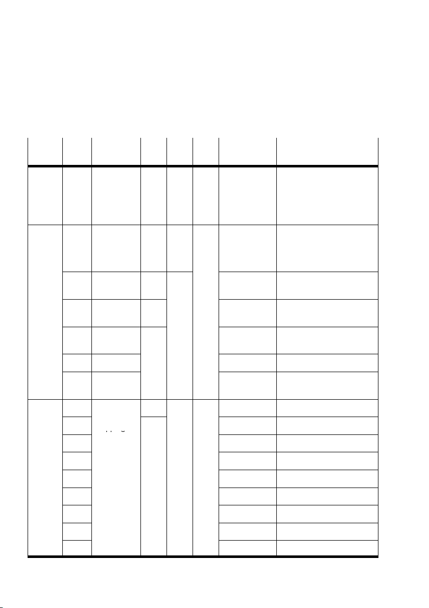
2. Commissioning
pp g
2.4.3 Digital inputs (transmit PDO 1)
Index
(hex)
181 Ū
1FF
1800 0 PDO com
1A00 0 PDO com
Sub
Designa
index
tion
Transmit
PDO 1
munication
parameter
record
1 PDO COB−ID U32 rw 180 + node ID Default COB−ID of the
2 Trans
mission type
3 Inhibit time U16 00 00 Transmit blocking time
4 not used
5 Event timer 00 00 Time−controlled trans
munication
1
mapping
parameter
2
Type Attr. Map. Values
Explanation
(hex)
xx xx Telegram length 1 Ū 8 bytes
U8 ro 05 Number of entries
U8 FF Default: Acyclic 1)
U8 rw 0 Ū 8 Number of entries
U32 60 00 01 08 Pointer at index I0 Ū I7
60 00 02 08 ... Index I8 Ū I15
Byte 0: I0 Ū I7
Byte 1: I8 Ū I15
...
Byte 7: I56 Ū I63
inputs
inputs [100s]
mission of the inputs [ms]
2−26
3 60 00 03 08 ... Index I16 Ū I23
4 60 00 04 08 ... Index I24 Ū I31
5 60 00 05 08 ... Index I32 Ū I39
6 60 00 06 08 ... Index I40 Ū I47
7 60 00 07 08 ... Index I48 Ū I55
8 60 00 08 08 ... Index I56 Ū I63
Festo P.BE−CPX−FB14−EN en 0810b
Page 73
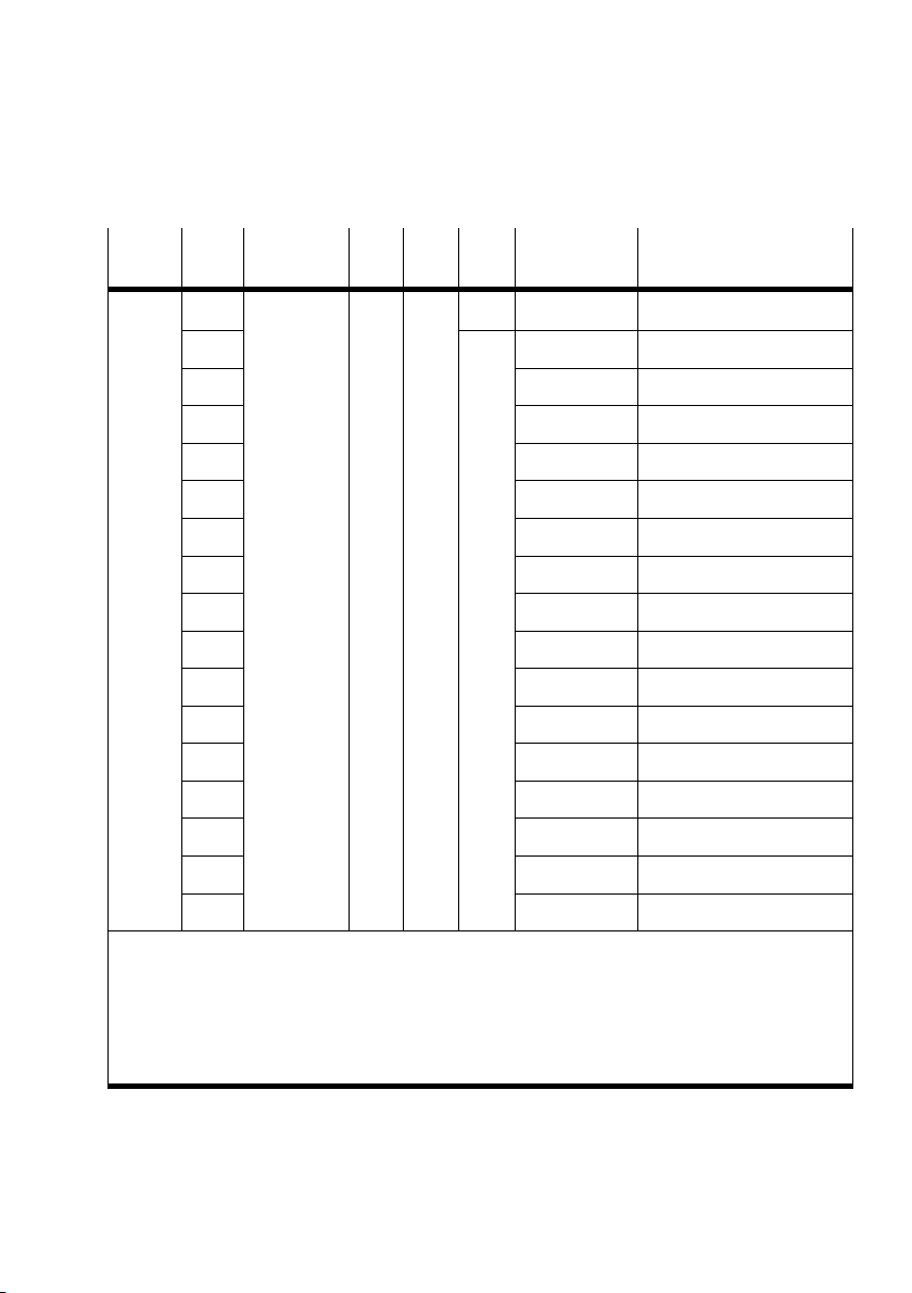
2. Commissioning
Index
(hex)
Sub
index
tion
6000 0 Read input
8bit
1
Map.Attr.TypeDesigna
(hex)
U8 ro 0 Ū 10 Number of 8−input groups
Yes xx Status of inputs 0 Ū 7
ExplanationValues
2 xx ... Inputs 8 Ū 15
3 xx ... Inputs 16 Ū 23
4 xx ... Inputs 24 Ū 31
5 xx ... Inputs 32 Ū 39
6 xx ... Inputs 40 Ū 47
7 xx ... Inputs 48 Ū 55
8 xx ... Inputs 56 Ū 63
9 xx ... Inputs 64 Ū 71
A
B
C
D
E
F
10
h
h
h
h
h
h
h
xx ... Inputs 72 Ū 79
xx ... Inputs 80 Ū 87
xx ... Inputs 88 Ū 95
xx ... Inputs 96 Ū 103
xx ... Inputs 104 Ū 111
xx ... Inputs 112 Ū 119
xx ... Inputs 120 Ū 127
U = unsigned Map. = mapping possible
ro = read only Attr. = attribute
rw = read/write
1)
During the transition from pre−operational to operational, the current SDO values will be frozen"
(e.g. analogue inputs). These values will be transmitted with each remote transmission request
(RTR), irrespective of further settings (e.g. interrupt enable for analogue inputs).
Festo P.BE−CPX−FB14−EN en 0810b
2−27
Page 74
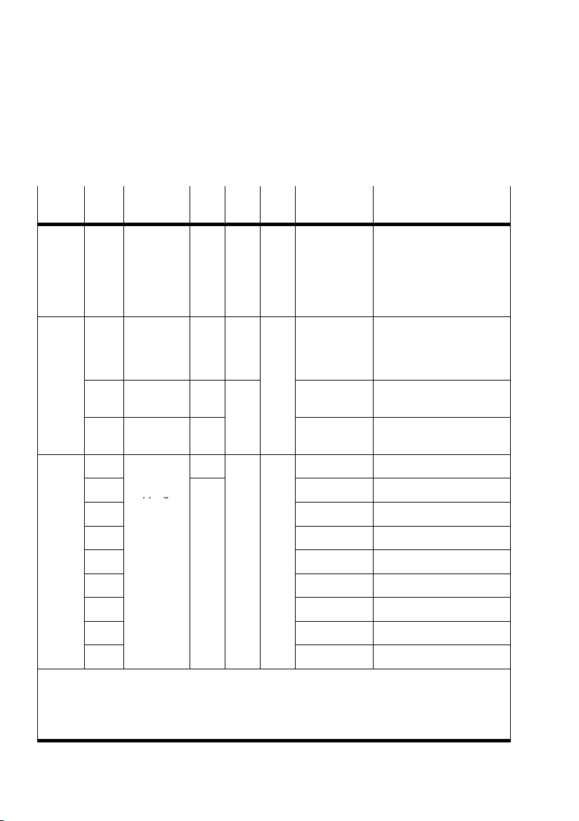
2. Commissioning
pp g
2.4.4 Digital outputs (receive PDO 1)
Index
(hex)
201 Ū
27F
1400 0 PDO com
1600 0 PDO com
Sub
Designa
index
tion
Receive
PDO 1
munication
parameter
record
1 PDO COB−ID U32 rw 200 + node ID Default COB−ID of the
2 Trans
mission type
munication
1
mapping
parameter
2
3 62 00 03 08 ... Index O16 Ū O23
4 62 00 04 08 ... Index O24 Ū O31
5 62 00 05 08 ... Index O32 Ū O39
Type Attr. Map. Values
Explanation
(hex)
xx xx xx xx Telegram length
1Ū8bytes
Byte 0: O0 Ū O7
Byte 1: O8 Ū O15
...
Byte 7: O56 Ū O63
U8 ro 02 Number of entries
outputs
U8 FF Default: acyclic
U8 rw 0 Ū 8 Number of entries
U32 62 00 01 08 Pointer at Index O0 Ū O7
62 00 02 08 ... Index O8 Ū O15
1)
6 62 00 06 08 ... Index O40 Ū O47
7 62 00 07 08 ... Index O48 Ū O55
8 62 00 08 08 ... Index O56 Ū O63
U = unsigned Map. = mapping possible
ro = read only Attr. = attribute
rw = read/write
1)
See remark in section 2.2.1.
2−28
Festo P.BE−CPX−FB14−EN en 0810b
Page 75
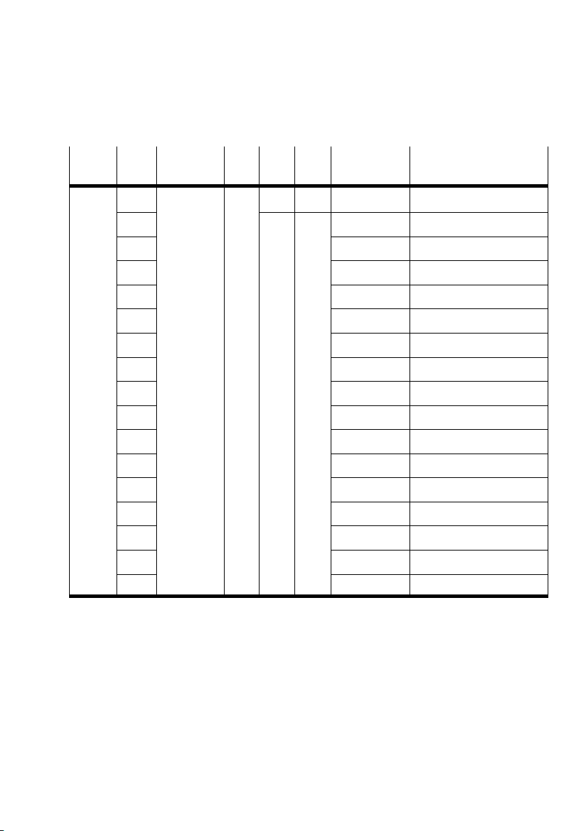
2. Commissioning
Index
(hex)
Sub
index
tion
6200 0 Write
output 8bit
1
2 xx ... Outputs 8 Ū 15
3 xx ... Outputs 16 Ū 23
4 xx ... Outputs 24 Ū 31
5 xx ... Outputs 32 Ū 39
6 xx ... Outputs 40 Ū 47
7 xx ... Outputs 48 Ū 55
8 xx ... Outputs 56 Ū 63
9 xx ... Outputs 64 Ū 71
A
h
B
h
C
h
D
h
E
h
F
h
10
h
Map.Attr.TypeDesigna
ExplanationValues
(hex)
U8 ro 0 Ū 10 Number of 8−output groups
rw Yes xx Status of outputs 0 Ū 7
xx ... Outputs 72 Ū 79
xx ... Outputs 80 Ū 87
xx ... Outputs 88 Ū 95
xx ... Outputs 96 − 103
xx ... Outputs 104 Ū 111
xx ... Outputs 112 Ū 119
xx ... Outputs 120 Ū 127
Festo P.BE−CPX−FB14−EN en 0810b
2−29
Page 76
2. Commissioning
Index
(hex)
Sub
index
tion
6206 0 Fault mode
output 8bit
1
2 FF ... Outputs 8 Ū 15
3 FF ... Outputs 16 Ū 23
4 FF ... Outputs 24 Ū 31
5 FF ... Outputs 32 Ū 39
6 FF ... Outputs 40 Ū 47
7 FF ... Outputs 48 Ū 55
8 FF ... Outputs 56 Ū 63
9 FF ... Outputs 64 Ū 71
A
h
B
h
C
h
D
h
E
h
F
h
10
h
Map.Attr.TypeDesigna
ExplanationValues
(hex)
U8 ro 0 Ū 10 Number of 8−output groups
rw FF Fault mode outputs 0 Ū 7
FF ... Outputs 72 Ū 79
FF ... Outputs 80 Ū 87
FF ... Outputs 88 Ū 95
FF ... Outputs 96 Ū 103
FF ... Outputs 104 Ū 111
FF ... Outputs 112 Ū 119
FF ... Outputs 120 Ū 127
2−30
Festo P.BE−CPX−FB14−EN en 0810b
Page 77
2. Commissioning
Index
(hex)
Sub
index
tion
6207 0 Error state
output 8bit
1
U8 ro 0 Ū 10 Number of 8−output groups
Map.Attr.TypeDesigna
(hex)
rw 00 Error state outputs 0 Ū 7
2 00 ... Outputs 8 Ū 15
3 00 ... Outputs 16 Ū 23
4 00 ... Outputs 24 Ū 31
5 00 ... Outputs 32 Ū 39
6 00 ... Outputs 40 Ū 48
7 00 ... Outputs 48 Ū 55
8 00 ... Outputs 56 Ū 63
9 00 ... Outputs 64 Ū 71
A
B
C
D
E
F
10
h
h
h
h
h
h
h
00 ... Outputs 72 Ū 79
00 ... Outputs 80 Ū 87
00 ... Outputs 88 Ū 95
00 ... Outputs 96 Ū 103
00 ... Outputs 104 Ū 111
00 ... Outputs 112 Ū 119
00 ... Outputs 120 Ū 127
U = unsigned Map. = mapping possible
ro = read only Attr. = attribute
rw = read/write
ExplanationValues
Festo P.BE−CPX−FB14−EN en 0810b
2−31
Page 78
2. Commissioning
The states of the valves and outputs of the CPX valve terminal
can be defined in case there should be a fault.
Note
With Index 6206 you can define the outputs which are to
assume a defined status in the event of a fault.
With Index 6207 you can define the status which the fixed
outputs are to assume in the event of a fault.
The settings do not become active until the CPX valve
terminal is put into the operational mode.
After each switching on or after each reset (hardware
initialization), the default values will automatically be
accepted, any maskings will be overwritten.
The following applies:
Index (hex)
6206
Subindex 1 Ū 10
Bit 0 Ū 7
6207
Subindex 1 Ū 10
Bit 0 Ū 7
2−32
Definition
0 = status of the output is retained
h
h
1 = output assumes the status defined in index 6207
0 = output is reset
1 = output is set
Festo P.BE−CPX−FB14−EN en 0810b
Page 79

2. Commissioning
2.4.5 Analogue inputs channel 0 Ū 3 (transmit PDO 2)
CANopen represents the 16−bit analogue values with the
following objects left justified in a 32−bit value:
6422, 6424, 6425, 6426, 6444, 5444, 5434
Values of an analogue input are loaded into the PDO only if
the following conditions are fulfilled:
Globale interrupt enable must be set to enable
(index6423).
With the interrupt trigger (index
6421), you can define
how the analogue value in the following step is to be
checked (minimum/maximum value, value modifica
tion, index 6424, 6425, 6426).
The channel number of the interrupt−triggering analogue
input is entered in Object 6422. The PDO is then transmitted
according to the transmission code in Object 1801
(FF
, FDh, FCh or 0 Ū F0h).
h
Festo P.BE−CPX−FB14−EN en 0810b
2−33
Page 80
2. Commissioning
Index
(hex)
281 Ū
2FF
1801 0 PDO commu
U = unsigned Map. = mapping possible
ro = read only Attr. = attribute
rw = read/write
1)
Sub
Designation Type Attr. Map. Values
index
Transmit
PDO2
nication
parameter
record
1 PDO COB−ID U32 rw 280h +
2 Transmission
type
3 Inhibit time U16 01 4F
4 not used
5 Event timer 00 00 Time−controlled
See remark on page 2−27
xx Telegram length 2, 4, 6 or
U8 ro 05 Number of entries
U8 FF Default: acyclic
(hex)
node ID
(= 50 ms)
Explanation
8bytes
Byte 0, 1: channel 0 (AI0)
Byte 2, 3: channel 1 (AI1)
Byte 4, 5: channel 3 (AI2)
Byte 6, 7: channel 4 (AI3)
Default COB−ID of the inputs
1)
Transmit blocking time
inputs [100s]
transmission of the inputs
[ms]
2−34
Festo P.BE−CPX−FB14−EN en 0810b
Page 81
2. Commissioning
pp g
Index
(hex)
1A01 0 PDO commu
6401 0 Read
6423 0 Analogue
Sub
Designation Type Attr. Map. Values
index
nication
1
mapping
parameters
2
3 64 01 03 10 ... Index AI2
4 64 01 04 10 ... Index AI3
5 00 00 00 00 ... at mapping object5
6 00 00 00 00 ... at mapping object6
7 00 00 00 00 ... at mapping object7
8 00 00 00 00 ... at mapping object8
analogue
input
1
2 xx AI1
3 xx AI2
4 xx AI3
input global
interrupt
enable
Explanation
(hex)
U8 rw 0 Ū 8 Number of entries
U32 64 01 01 10 Pointer at Index AI0
64 01 02 10 ... Index AI1
U8 ro 0 Ū 10 Number of analogue
channels
I16 Yes xx AI0
B rw 00 Globale interrupt enable
0 = disable
1 = enable
6422 0 Analogue
1)
Reset automatically after read access
Festo P.BE−CPX−FB14−EN en 0810b
input number
of interrupt
source banks
1 Interrupt
source bank 1
U8 ro 1 Number of interrupt source
U32 00 Interrupt source bank 1
banks
1)
(channel 0 Ū 15)
2−35
Page 82
2. Commissioning
Index
(hex)
6421 0 Analogue
index
U8 ro 0 Ū 10 Number of analogue inputs
Map.Attr.TypeDesignationSub
input interrupt
trigger
selection
1 Analogue
rw 00 AI0
input
2 00 AI1
3 00 AI2
4 00 AI3
6424 0 Analogue
U8 ro 0 Ū 10 Number of analogue inputs
input interrupt
upper limit
integer
1 Analogue
input
2
I32 rw 00 Maximum value AI0
3 00 Maximum value AI2
4 00 Maximum value AI3
1)
Bit 0: Upper limit exceeded" (as per DS401)
2)
Bit 1: Input below lower limit" (as per DS401)
3)
Bit 2: Input changed by more than delta" (as per DS401)
ExplanationValues
(hex)
Bit 0: Upper limit value
exceeded
Bit 1: Lower limit value
exceeded
Bit 2: Modification greater
than delta
Bit 3 Ū 7: reserved
00 Maximum value AI1
1)
2)
3)
1)
1)
1)
1)
2−36
Festo P.BE−CPX−FB14−EN en 0810b
Page 83
2. Commissioning
Index
(hex)
6425 0 Analogue
index
U8 ro 0 Ū 10 Number of analogue inputs
Map.Attr.TypeDesignationSub
input interrupt
upper limit
integer
1 Analogue
input
2
I32 rw 00 Minimum value AI0
3 00 Minimum value AI2
4 00 Minimum value AI3
6426 0 Analogue
U8 ro 0 Ū 10 Number of analogue inputs
input interrupt
delta
unsigned
1 Analogue
U32 rw 00 Minimum value modification
input
2 00 Minimum value modification
3 00 Minimum value modification
4 00 Minimum value modification
2)
Bit 1: Input below lower limit" (as per DS401)
3)
Bit 2: Input changed by more than delta" (as per DS401)
ExplanationValues
(hex)
00 Minimum value AI1
3)
AI0
3)
AI1
3)
AI2
3)
AI3
2)
2)
2)
2)
Festo P.BE−CPX−FB14−EN en 0810b
2−37
Page 84
2. Commissioning
pp g
2.4.6 Analogue outputs channel 0 Ū 3 (Receive PDO 2)
Index
(hex)
301 Ū
37F
1401 0 PDO commu−
1601 0 PDO commu−
Sub
Designation Type Attr. Map. Values
index
Receive PDO 2 xx Telegram length 2, 4, 6 or
nication
parameter
record
1 PDO COB−ID U32 rw 300 +
2 Transmission
type
nication
1
mapping
parameters
2
3 64 11 03 10 ... Index AO2
4 64 11 04 10 ... Index AO3
5 00 00 00 00 ... at mapping object5
Explanation
(hex)
8bytes
Byte 0, 1: channel 0 (AO0)
Byte 2, 3: channel 1 (AO1)
Byte 4, 5: channel 2 (AO2)
Byte 6, 7: channel 3 (AO3)
U8 ro 02 Number of entries
Default COB−ID of the inputs
nodeID
U8 FF Default: acyclic
U8 rw 0 Ū 8 Number of entries
U32 64 11 01 10 Pointer at index AO4
64 11 02 10 ... Index AO1
2−38
6 00 00 00 00 ... at mapping object6
7 00 00 00 00 ... at mapping object7
8 00 00 00 00 ... at mapping object8
Festo P.BE−CPX−FB14−EN en 0810b
Page 85
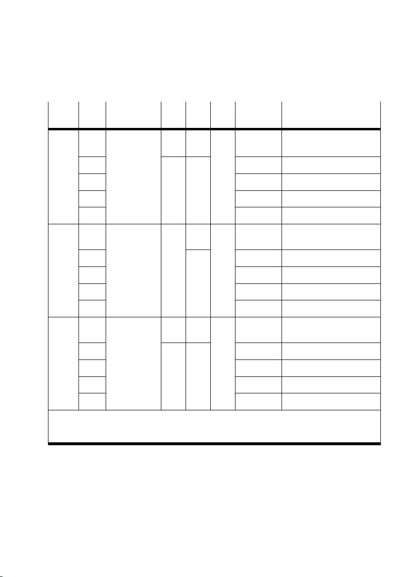
2. Commissioning
Index
(hex)
6411 0 Write
6443 0 Analogue
6444 0 Analogue
index
analogue
output 16 bit
1
2 xx xx AO1
3 xx xx AO2
4 xx xx AO3
output fault
mode
1
2 1 Default mode AO1
3 1 Default mode AO2
4 1 Default mode AO3
output error
integer 32 bit
1
2 2 Error value AO1
3 3 Error value AO2
Map.Attr.TypeDesignationSub
ExplanationValues
(hex)
U8 ro Yes 0 Ū 10 Number of analogue
I16 rw xx xx AO0
U8 ro 0 Ū 10 Number of analogue
rw 1 Default mode AO0
U8 ro 0 Ū 10 Number of analogue
I32 rw 1 Error value AO0
channels
channels
channels
4 4 Error value AO3
U = unsigned Map. = mapping possible
ro = read only Attr. = attribute
rw = read/write
Festo P.BE−CPX−FB14−EN en 0810b
2−39
Page 86
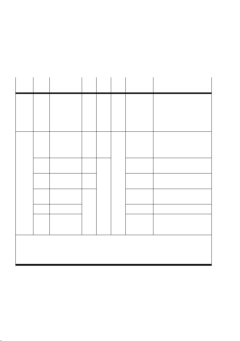
2. Commissioning
2.4.7 Analogue inputs channel 4 Ū 15 (Transmit PDO 3)
Index
(hex)
381 Ū
3FF
1802 0 PDO commu−
U = unsigned Map. = mapping possible
ro = read only Attr. = attribute
rw = read/write
1)
Sub
Designation Type Attr. Map. Values
index
Transmit
PDO3
nication
parameter
record
1 PDO COB−ID U32 rw 380 +
2 Transmission
type
3 Inhibit time U16 01 F4
4 not used
5 Event timer 00 00 Time−controlled
See remark on page 2−27
xx Telegram length 2, 4, 6 or
U8 ro 05 Number of entries
U8 FF Default: acyclic
(hex)
nodeID
(= 50 ms)
Explanation
8bytes
Byte 0, 1: channel 4 (AI4)
Byte 2, 3: channel 5 (AI5)
Byte 4, 5: channel 6 (AI6)
Byte 6, 7: channel 7 (AI7)
Default COB−ID of the inputs
1)
Transmit blocking time
inputs [100s]
transmission of the inputs
[ms]
2−40
Festo P.BE−CPX−FB14−EN en 0810b
Page 87
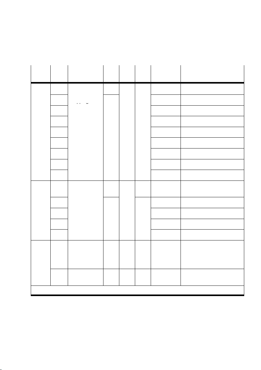
2. Commissioning
pp g
Index
(hex)
1A02 0 PDO commu−
6401 0 Read
6422 0 Analogue
1)
index
nication
1
mapping
parameters
2
3 64 01 07 10 ... Index AI6
4 64 01 08 10 ... Index AI7
5 00 00 00 00 ... at mapping object5
6 00 00 00 00 ... at mapping object6
7 00 00 00 00 ... at mapping object7
8 00 00 00 00 Pointer at mapping object8
analogue
input
5
6 xx xx AI5
... ... ...
10
h
input number
of interrupt
source banks
1 Interrupt
source bank 1
Reset automatically after read access
Values
Map.Attr.TypeDesignationSub
Explanation
(hex)
U8 rw 0 Ū 8 Number of entries
U32 64 01 05 10 Pointer at index AI4
64 01 06 10 ... Index AI5
U8 ro 0 Ū 10 Number of analogue
I16 Yes xx xx AI4
xx xx AI15
U8 ro 1 Number of interrupt source
U32 ro 00 Interrupt source bank 1
channels
banks (see PDO 2)
1)
(channel 1 Ū 16)
Festo P.BE−CPX−FB14−EN en 0810b
2−41
Page 88
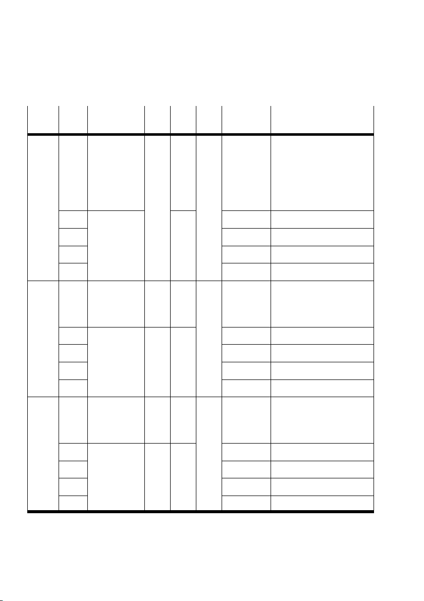
2. Commissioning
Index
(hex)
6421 0 Analogue
6424 0 Analogue
6425 0 Analogue
index
input interrupt
trigger
selection
number of
analogue
input
5 Analogue
input
6
... ... ...
10
h
input interrupt
upper limit
integer
5 Analogue
input
6
... ... ...
10
h
input interrupt
upper limit
integer
Values
Map.Attr.TypeDesignationSub
Explanation
(hex)
U8 ro 0 Ū 10 Number of analogue inputs
rw 00 AI4
00 AI5
00 AI15
U8 ro 0 Ū 10 Number of analogue inputs
I32 rw 00 Maximum value AI4
00 Maximum value AI5
00 Maximum value AI15
U8 ro 0 Ū 10 Number of analogue inputs
2−42
5 Analogue
input
6
... ... ...
10
h
I32 rw 00 Minimum value AI4
00 Minimum value AI5
00 Minimum value AI15
Festo P.BE−CPX−FB14−EN en 0810b
Page 89
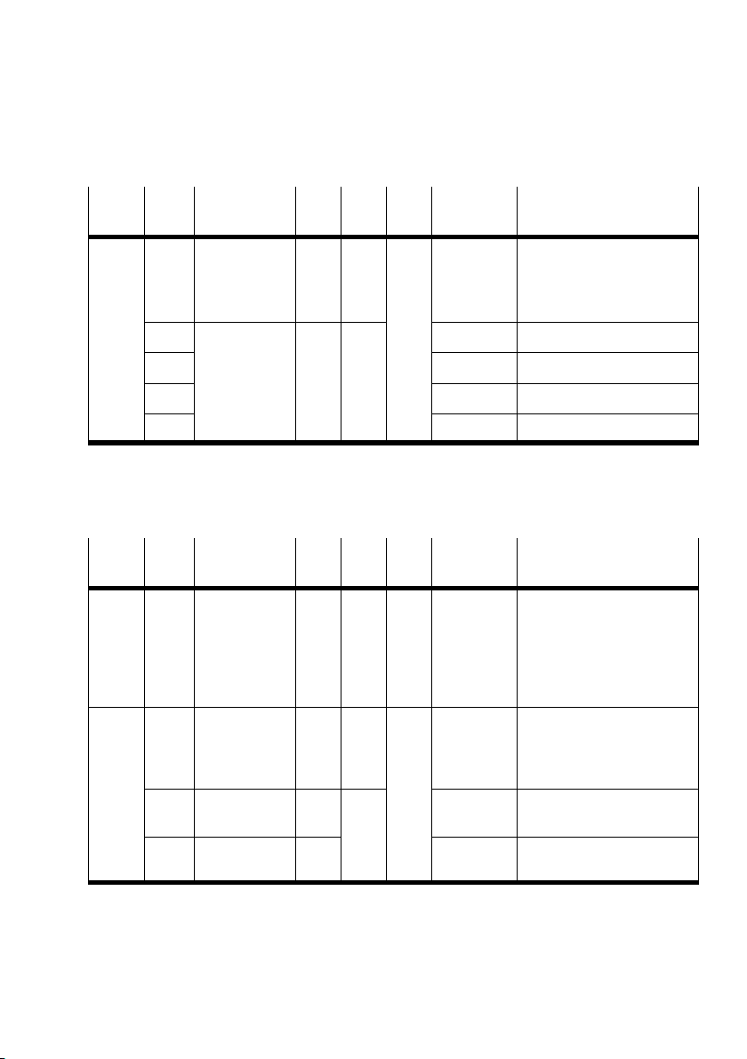
2. Commissioning
Index
(hex)
6426 0 Analogue
index
input interrupt
delta
unsigned
5 Analogue
input
6
... 00 ...
10
h
U8 ro 0 Ū 10 Number of analogue inputs
U32 rw 00 Minimum value change AI4
Values
Map.Attr.TypeDesignationSub
Explanation
(hex)
00 Minimum value change AI5
00 Minimum value change AI15
2.4.8 Analogue outputs channel 4 Ū 15 (Receive PDO 3)
Index
(hex)
401 Ū
47F
Sub
Designation Type Attr. Map. Values
index
Receive PDO 3 xx Telegram length 2, 4, 6 or
(hex)
Explanation
8bytes
Byte 0, 1: channel 5 (AO4)
Byte 2, 3: channel 6 (AO5)
Byte 4, 5: channel 7 (AO6)
Byte 6, 7: channel 8 (AO7)
1402 0 PDO commu−
nication
parameter
record
1 PDO COB−ID U32 rw 400 +
2 Transmission
type
Festo P.BE−CPX−FB14−EN en 0810b
U8 ro 02 Number of entries
Default COB−ID of the inputs
node ID
U8 FF Default: acyclic
2−43
Page 90
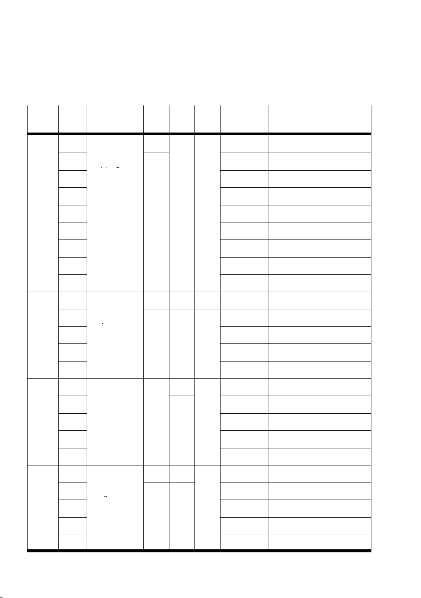
2. Commissioning
pp g
p
g
Index
(hex)
1602 0 PDO commu−
6411 0 Write
6443 0 Analogue
index
nication
1
mapping
parameters
2
3 64 11 07 10 ... Index AO6
4 64 11 08 10 ... Index AO7
5 00 00 00 00 ... at mapping object5
6 00 00 00 00 ... at mapping object6
7 00 00 00 00 ... at mapping object7
8 00 00 00 00 ... at mapping object8
analogue
5
output 16bit
6
... ... ...
10
h
output fault
5
mode
6 1 Default mode AO5
Map.Attr.TypeDesignationSub
ExplanationValues
(hex)
U8 rw 0 Ū 8 Number of entries
U32 64 11 05 10 Pointer at Index AO4
64 11 06 10 ... Index AO5
U8 ro 0 Ū 10 No. of analogue channels
I16 rw Yes xx AO4
xx AO5
xx AO15
U8 ro 0 Ū 10 No. of analogue channels
rw 1 Default mode AO4
... ... ...
10
h
6444 0 Analogue
5
6
... ... ...
10
h
2−44
output error
integer 32 bit
1 Default mode AO15
U8 ro 0 Ū 10 No. of analogue channels
I32 rw 00 00 00 00 Error value AO4
00 00 00 00 Error value AO5
00 00 00 00 Error value AO15
Festo P.BE−CPX−FB14−EN en 0810b
Page 91
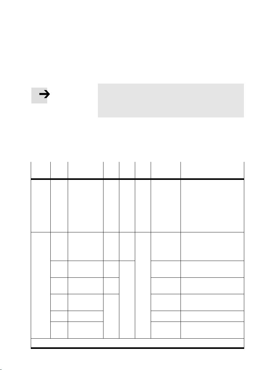
2. Commissioning
2.4.9 Technology modules, status bits, I/O diagnostic interface (PDO 4)
Note
In order to use the status bits or the I/O diagnostic
interface, you must activate them with the DIL switches on
the field bus node (see section 1.2.2).
Further information on the status bits and on the I/O
diagnostic interface can be found in section 3.3 and 3.4.
Transmit PDO 4
Index
(hex)
481 Ū
4FF
1803 0 PDO commu−
1)
Sub
Designation Type Attr. Map. Values
index
Transmit
PDO4
nication
parameter
record
1 PDO COB−ID U32 rw 480 + nodeIDDefault COB−ID of the inputs
2 Transmission
type
3 Inhibit time U16 00 00 Transmit blocking time
4 not used
5 Event timer 00 00 Time−controlled trans
See remark on page 2−27
Explanation
(hex)
xx Telegram length 2, 4, 6 or
U8 ro 05 Number of entries
U8 FF Default: acyclic
8bytes
Byte 0, 1: Status bits or I/O
diagnostic interface (de
pending on configuration)
Byte 2, 3: reserved
Byte 4, 5: reserved
Byte 6, 7: reserved
1)
inputs [100s]
mission of the inputs [ms]
Festo P.BE−CPX−FB14−EN en 0810b
2−45
Page 92
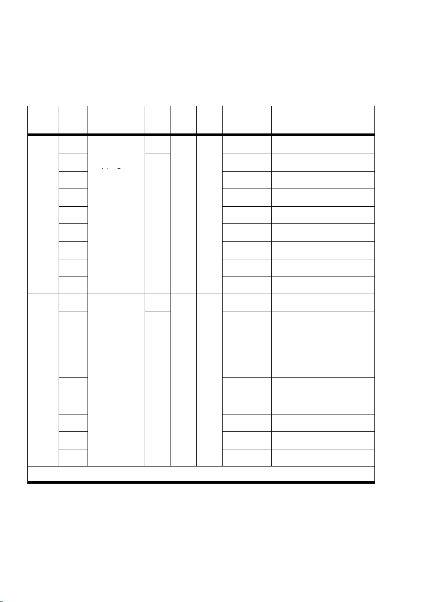
2. Commissioning
pp g
Index
(hex)
1A03 0 PDO commu−
6100 0 Read input
index
nication
1
mapping
parameters
2
3 61 00 03 10 ... at IW2
4 61 00 04 10 ... at IW3
5 00 00 00 00 ... at mapping object5
6 00 00 00 00 ... at mapping object6
7 00 00 00 00 ... at mapping object7
8 00 00 00 00 ... at mapping object8
16bit
1
2 xx IW1: depending on
Map.Attr.TypeDesignationSub
ExplanationValues
(hex)
U8 rw 0 Ū 8 Number of entries
U32 61 00 01 10 Pointer at IW0
61 00 02 10 ... at IW1
U8 ro Yes 0 Ū 20 Number of IW groups
U16 xx IW0, depending on
configuration1):
status bits or
I/O diagnostic interface
1. input word technology
module
configuration: 1. or 2. input
word technology module
1)
3 xx IW2 technology module
... ... ...
20
h
1)
Depending on diagnostic setting
2−46
xx IW31 technology module
Festo P.BE−CPX−FB14−EN en 0810b
Page 93
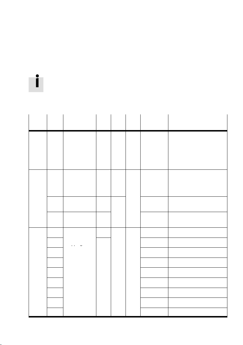
2. Commissioning
pp g
Sub
Index
(hex)
Designation Type Attr. Map. Values
index
Receive PDO 4
A description of the method of operation of the I/O diagnostic
interface can be found in the Diagnosis chapter of the CPX
System Description.
Explanation
(hex)
501 Ū
57F
1403 0 PDO commu−
1603 0 PDO commu−
Receive PDO4 xx Telegram length 1 Ū 8 bytes
nication
parameter
record
1 PDO COB−ID U32 rw 500 +
2 Transmission
type
nication
1
mapping
parameters
2
3 63 00 03 10 ... at OW2
4 63 00 04 10 ... at OW3
5 00 00 00 00 ... at mapping object5
6 00 00 00 00 ... at mapping object6
7 00 00 00 00 ... at mapping object7
Byte 0, 1: I/O diagnostic
interface (if configured)
Byte 2, 3: reserved
Byte 4, 5: reserved
Byte 6, 7: reserved
U8 ro 02 Number of entries
Default COB−ID of the inputs
node ID
U8 FF Default: acyclic
U8 rw 0 Ū 8 Number of entries
U32 63 00 01 10 Pointer at OW0
63 00 02 10 ... at OW1
8 00 00 00 00 ... at mapping object8
Festo P.BE−CPX−FB14−EN en 0810b
2−47
Page 94
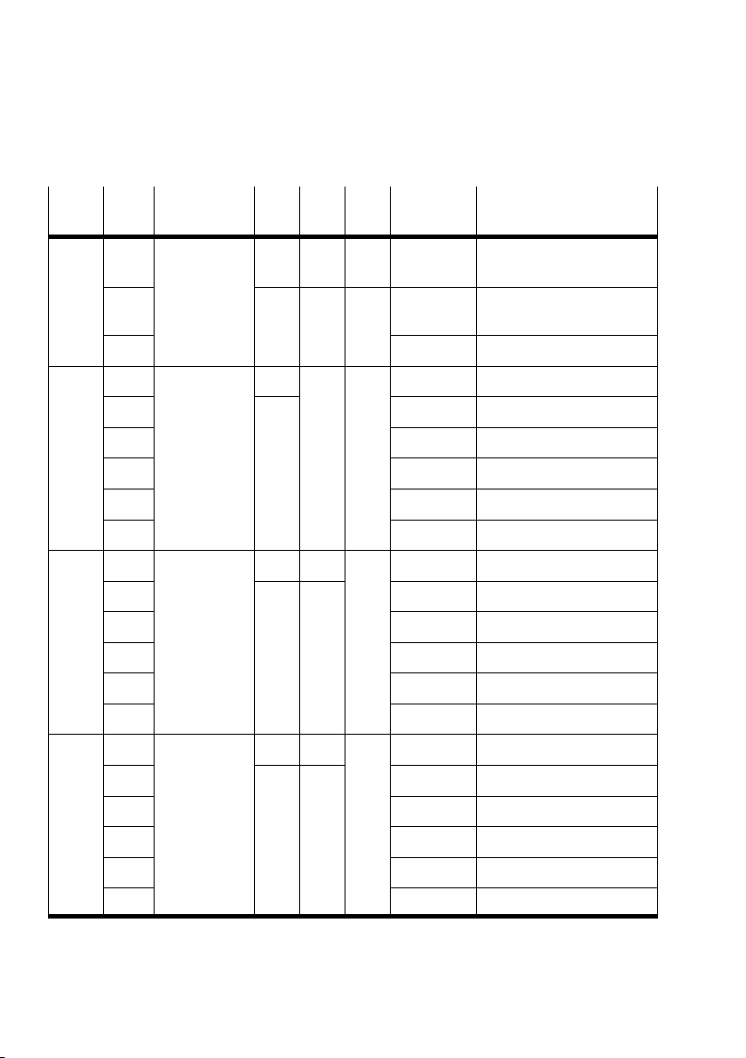
2. Commissioning
Index
(hex)
6300 0 Write output
6300 0 Write output
6306 0 Fault mode
index
16bit
1 U16 rw Yes xx If configured:
2 Ū 8 reserved
16bit
1
2 xx OW1 technology module
3 xx OW2 technology module
... ... ...
20
h
output 16 bit
1
2 FF FF ... OW1
3 FF FF ... OW2
... ... ...
Map.Attr.TypeDesignationSub
ExplanationValues
(hex)
U8 ro 0 Ū 8 Number of 16−output
U8 rw Yes 0 Ū 20 Number of OW groups
U16 xx OW0 technology module
xx OW31 technology module
U8 ro 0 Ū 20 Number of OW groups
U16 rw FF FF Fault mode OW0
groups
I/O diagnostic interface
20 FF FF ... OW31
6307 0 Error state
output 16 bit
1
2 00 00 ... OW1
3 00 00 ... OW2
... ... ...
20 00 00 ... OW31
2−48
U8 ro 0 Ū 20 Number of OW groups
U16 rw 00 00 Fault mode OW0
Festo P.BE−CPX−FB14−EN en 0810b
Page 95
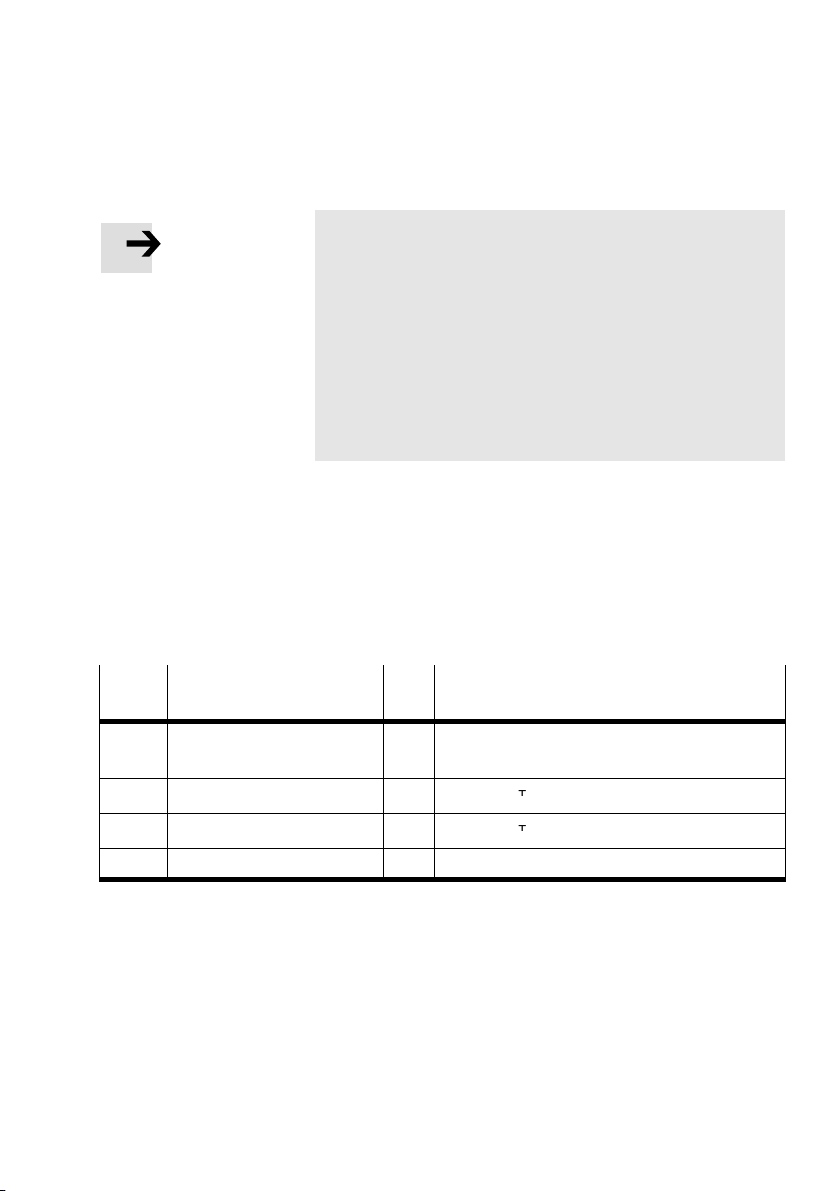
2. Commissioning
2000
System data
Operating mode, details see Tab.2/10
Note
With Index 6306 you can define the outputs which are to
assume a defined status in the event of an error.
With Index 6307 you can define the status which the fixed
outputs are to assume in the event of an error.
The settings do not become active until the CPX valve
terminal is put into the operational mode.
After each switching on or after each reset (hardware
initialization), the default values will automatically be
accepted, any maskings will be overwritten.
2.4.10 Manufacturer specific profile
Further information can be found in the following tables and
in the CPX System Description (P.BE−CPX−SYS−...).
Index
Designation Map. Explanation
(hex)
2000 System data Operating mode, details see Tab.2/10
2010 Module data Details see Tab.2/11
2200 System diagnostic data Yes Details see Tab.2/12
2210 Module diagnostic data Details see Tab.2/13
(global system configuration)
Tab.2/9: Overview of the indices of the manufacturer specific profile area
Festo P.BE−CPX−FB14−EN en 0810b
2−49
Page 96
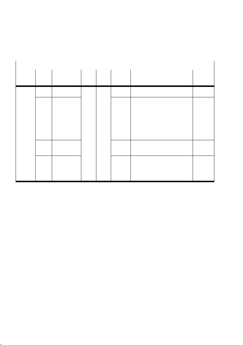
2. Commissioning
System data
Index
(hex)
2000 0 System data U8 ro 3 Number of parameters
Sub
index
Designa
tion
Type Attr. Values
(hex)
Explanation Func
tion no.
1 Operating
mode1
2 Fail safe xx See index 6206, 6207, 6306,
3 Monitoring
the CPX
terminal
Tab.2/10: System data
xx CPX operating mode
Bit 0 Ū 3: CPX operating
mode
Bit 4: CPX expansion
Bit 5: Handheld
Bit 6: Force mode
Bit 7: System start
6307
xx Monitoring the CPX terminal:
Bit 0 Ū 3: short circuit/over
load/undervoltage
Bit 4 Ū 7: reserved
0000
0001
0002
2−50
Festo P.BE−CPX−FB14−EN en 0810b
Page 97
2. Commissioning
serial
xx
Module data
Index
(hex)
Sub
index
Designa
tion
Type Attr. Values
(hex)
Explanation Func
tion no.
2010 0 Module data U8 ro 1 Ū Number of entries 16 + xx
1 Module0 U16 xx xx Module type
2 Module1 xx xx Module type
3 Module2 xx xx Module type
... ... ... ...
2110 0 U8 ro 1 Ū Number of entries 784 + xx
1 Module
serial
number
Module 0
2 Module
serial
number
Module 1
... ... ... ...
1)
All details: See appendix in CPX system manual
U32 xx
xx
xx
xx
U32 xx
xx
xx
xx
(module code + revision code)
(module code + revision code)
(module code + revision code)
Module serial number
1)
1)
1)
1)
Tab.2/11: Module data
1)
1)
Festo P.BE−CPX−FB14−EN en 0810b
2−51
Page 98
2. Commissioning
module 0
00
FF
Fault number
xx
)
System diagnostic data
Index
(hex)
2200 0 U8 ro 8 Number of entries
Sub
Designa
index
tion
1 Status byte 0 Ū FF Status bits 1936
Type Attr. Values
(hex)
Explanation Func
tion no.
2 Module
number
3 Error
number
4 Ū 8 reserved reserved 1939Ū
0,40,ŪNumber of the module with
diagnostic message
(bit 0Ū5)
Diagnosis completed (bit 6)
0 Ū FF Fault number 1938
Tab.2/12: System diagnostic data (PDO mapping is possible)
Module diagnostic data
Index
(hex)
2210 0 Module
Sub
Designa
index
tion
diagnostics
1 Diagnostic
module 0
2 Diagnostic
module 1
Type Attr. Values
Explanation Func
(hex)
U8 ro 1 Ū Number of entries
U32 ro 00 Ū FF
00 Ū FF
00
00
00 Ū FF
00 Ū FF
00
00
I/O channel/channel number
Fault number
Ū
reserved
reserved
I/O channel/channel number
Fault number
reserved
reserved
1937
1943
tion no.
2008 +
1)
xx
... ... ... ...
1)
All details: See appendix in CPX system manual
Tab.2/13: Module diagnostic data
2−52
Festo P.BE−CPX−FB14−EN en 0810b
Page 99
2. Commissioning
g
00
3B
3
Numb
00
63
Number of 10 ms
1stmessage after power−on)
00
2F
Module position
Diagnostic memory parameters and data
Index
(hex)
Sub
index
Designa
tion
Type Attr. Values
(hex)
Explanation Func
tion no.
2300 0 Status/
2310 0 Diagnosis
mode
1
diagnostic
memory
2
3 rw 00 Number of entries in the
4 ro 00 Current status / overrun 3483
5 rw 00 Trigger conditions
6 00 Module number (MN) 3485
7 00 Channel number (CN) 3486
8 00 Fault number (FN) 3487
memory
1 1. Entry
(latest error)
2 2. entry
3 3. entry
... ...
28
40. entry
h
(oldest
saved error)
U8 ro 8 Number of entries
rw xx Diagnostic memory mode 3480
diagnostic memory
(writing 0" will delete all
entries)
(Run/stop filter 2, error
end filter, fault number filter,
module/channel filter)
U8 ro 0 Ū 28 Number of entries
Oct.
string
00 Ū FF
00 Ū 17
Ū
00 Ū 3B
00 Ū 6
Ū
(+ 80)
00 Ū FF
00 Ū 2F
Ū
00 Ū FF
00 Ū FF
00 Ū FF
Number of days
Number of hours
er of minutes
Number of seconds
Number of 10 ms
(and designation for
1stmessage after power−on)
Module code
Module position
Channel number
Fault number
Following channels
3482
3484
3488,
Ū
Tab.2/14: Diagnostic memory data
Festo P.BE−CPX−FB14−EN en 0810b
2−53
Page 100
2. Commissioning
System parameters
Index
(hex)
Sub
index
Designa
tion
Type Attr. Values
(hex)
Explanation Func
tion no.
2400 0 System
1)
At system start with saved parameterization, only the objects 2000Ū5FFF are loaded.
The objects 6000Ū are always loaded with the default settings after power−on.
parameters
1 Parameter
byte 0
2 Parameter
byte 1
3 Parameter
byte 2
4 Ū 8 reserved reserved
U8 ro 8 Number of entries
rw 0 Ū FF reserved 4400
0 Ū FF Monitoring (active/inactive) 4401
0 Ū FF Bit 0, 1: not implemented
Bit 2, 3: Force mode
Bit 4, 5: not implemented
Bit 6, 7: System start
Tab.2/15: System parameters
Detailed information on parameters and data can be found in
the CPX system manual.
4402
1)
2−54
Festo P.BE−CPX−FB14−EN en 0810b
 Loading...