

Page 1
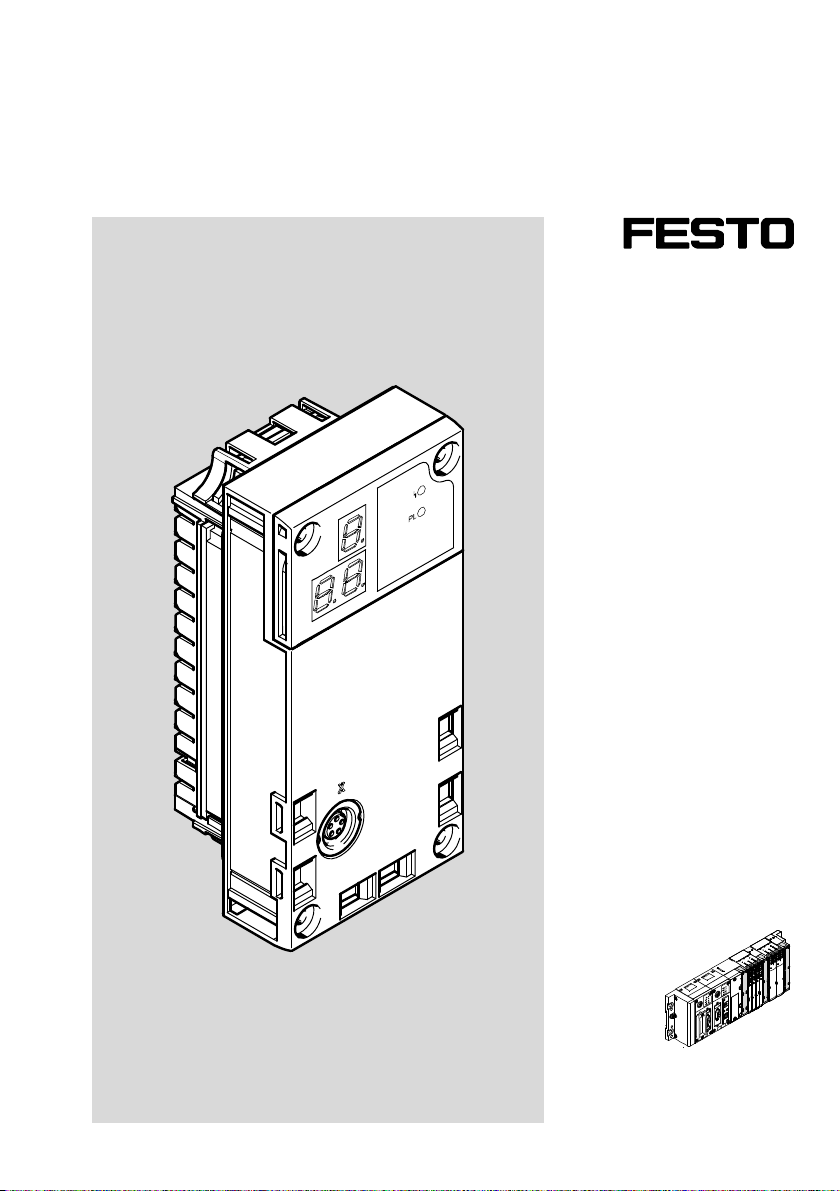
Terminal CPX
Control block CPX-CM-HPP
Description
FHPP interface
Description
568684
2017-06b
[8070655]
Page 2

Page 3

Contents and general instructions
Original instructions
Version 2017-06b..................................
Designation CPX-CM-HPP-EN.........................
Order no. 568684..................................
© (Festo AG & Co. KG, 73734 Esslingen, Germany, 2017)
Internet:http://www.festo.com
E-Mail: [email protected]
Reproduction, distribution or sale of this document or
communication of its contents to others without
express authorization is prohibited. Offenders will be held
liable for damages. All rights are reserved, in particular the
right to file patent, utility model or registered design
applications.
Festo CPX-CM-HPP-EN 2017-06b English
I
Page 4

Contents and general instructions
PI PROFIBUS PROFINET®, DeviceNet® are registered trademarks of the respective
trademark owners in certain countries.
II
Festo CPX-CM-HPP-EN 2017-06b English
Page 5

Contents and general instructions
Contents
Intended use VII..........................................................
Target group VIII..........................................................
Service VIII...............................................................
Important user information IX..............................................
Safety instructions XI.....................................................
Notes regarding this description XIII..........................................
Glossary XV..............................................................
1. System summary 1-1...............................................
1.1 The CPX-CM-HPP 1-3...............................................
1.1.1 Functions and key features 1-3................................
1.1.2 Tasks 1-3.................................................
1.2 Supported motor controllers 1-4......................................
1.3 Control options 1-5.................................................
1.4 System configurations 1-6...........................................
1.4.1 Autonomous automation solution 1-6..........................
1.4.2 Control of the CPX terminal through the higher-order controller 1-7..
1.4.3 Autonomous automation solution with
communication with ahigher-order controller 1-8................
1.5 Connection and display components 1-9...............................
2. Fitting and installation 2-1..........................................
2.1 General instructions for installation 2-3................................
2.2 Dismantling and mounting 2-4.......................................
2.2.1 Dismounting 2-4...........................................
2.2.2 Mounting 2-5..............................................
2.3 Axis connection (CAN bus interface) 2-6................................
2.4 Connecting the CAN bus 2-7.........................................
2.4.1 CAN bus line 2-7...........................................
2.4.2 Terminating resistor 2-8.....................................
Festo CPX-CM-HPP-EN 2017-06b English
III
Page 6

Contents and general instructions
3. Commissioning 3-1................................................
3.1 General instructions on commissioning 3-3.............................
3.2 Communication profile FHPP 3-4......................................
3.2.1 Overview of FHPP data structure 3-5...........................
3.3 Communication between CPX-CM-HPP and the motor controllers 3-9........
3.4 Commissioning 3-10.................................................
3.5 Parameterisation of the connected motor controllers with FCT 3-12...........
3.5.1 Prerequisite for commissioning motor controllers with FCT 3-12......
3.5.2 Commissioning motor controllers 3-12...........................
3.5.3 Specific settings for motor controllers CMMD-AS, CMMS-AS
and CMMS-ST 3-14..........................................
3.5.4 Specific settings for motor controller CMMP-AS 3-16...............
3.5.5 Specific settings for motor unit MTR-DCI--...-CO 3-17...............
3.5.6 Specific settings for motor controller SFC-DC-...-CO 3-18............
3.5.7 Specific settings for motor controller SFC-LAC-...-CO 3-19...........
3.5.8 Specific settings for planar surface gantry EXCM with controller 3-19..
3.5.9 Specific settings for integrated drive EMCA 3-20..................
3.5.10 Specific settings for controller CMXH 3-20........................
3.6 Configuration of the CPX-CM-HPP 3-21..................................
3.6.1 Configuration parameters 3-21.................................
3.6.2 Description Configuration parameters 3-22.......................
3.6.3 Other parameters: 3-25.......................................
3.6.4 Configuration with the MMI 3-26...............................
3.6.5 Configuration with CPX-FMT 3-28...............................
3.7 Force 3-30.........................................................
4. Diagnostics and error treatment 4-1..................................
4.1 Summary of diagnostics options 4-3...................................
4.2 Errors and warnings 4-4.............................................
4.2.1 Behaviour in case of errors and warnings 4-4....................
4.2.2 Acknowledge errors 4-4.....................................
4.2.3 Error numbers 4-5..........................................
4.3 Diagnostics via display 4-11..........................................
4.4 Diagnostics via LEDs 4-13............................................
IV
Festo CPX-CM-HPP-EN 2017-06b English
Page 7

Contents and general instructions
4.5 Diagnostics at the CPX terminal 4-15...................................
4.5.1 Status bits in the system status of the CPX terminal 4-15............
4.5.2 I/O diagnostic interface and diagnostic memory 4-16..............
4.5.3 Definition of diagnostics channels 4-19..........................
A. Technical appendix A-1.............................................
A.1 Technical data A-3..................................................
A.2 Accessories A-4....................................................
A.3 Device-specific information on the CPX-MMI handheld A-5.................
B. Index B-1.........................................................
Festo CPX-CM-HPP-EN 2017-06b English
V
Page 8

Contents and general instructions
VI
Festo CPX-CM-HPP-EN 2017-06b English
Page 9

Contents and general instructions
Intended use
The module CPX-CM-HPP documented in this description is
intended exclusively for use in CPX terminals from Festo for
installation in a machine or automated system.
The CPX-CM-HPP in combination with a controller allows the
independent actuation of up to four drives via CAN bus.
The CPX terminal with the CPX-CM-HPP must only be used as
follows:
– As intended in an industry segment.
– in its original state without unauthorised modifications.
– in perfect technical condition.
– only in combination with approved components For an
Only the conversions or modifications described in the
documentation supplied with the product are permitted.
overview of supported motor controllers, refer to
Tab. 1/4.
Festo CPX-CM-HPP-EN 2017-06b English
The limit values specified for pressures, temperatures,
electrical data, torques etc. must be observed.
Observe the regulations of the trade associations, German
Technical Control Board (TÜV), VDE stipulations or
corresponding national laws and regulations.
VII
Page 10

Contents and general instructions
Target group
This description is intended exclusively for technicians
trained in control and automation technology who have
experience in installation, commissioning, programming and
diagnostics of positioning systems.
Service
Please contact your local Festo service if you have any
technical problems.
VIII
Festo CPX-CM-HPP-EN 2017-06b English
Page 11
Contents and general instructions
Important user information
Danger categories
This description includes instructions on the possible dangers
that can occur if the product is used incorrectly. These notes
are marked with a signal word (Warning, Caution, etc),
printed on a shaded background and marked additionally
with a pictogram. A distinction is made between the following
danger warnings:
Warning
... means that non-observance can result in serious
personal injury or damage to property.
Caution
... means that injury to people and damage to property can
occur if this warning is not observed.
Festo CPX-CM-HPP-EN 2017-06b English
Note
... means that damage to property can occur if this warning
is not observed.
In addition, the following pictogram marks passages in the
text that describe activities involving electrostatic sensitive
devices:
Electrostatically sensitive devices: Incorrect handling can
cause damage to devices.
IX
Page 12

Contents and general instructions
Marking of special information
The following pictograms mark passages in the text that
contain special information.
Pictograms
Information:
Recommendations, tips and references to other information
sources.
Accessories:
Information about necessary or useful accessories for the
Festo product.
Environment:
Information about environmentally friendly use of products
from Festo.
Text designations
Bullet points denote activities that can be carried out in
any order.
1. Numerals label activities that must be carried out in the
sequence specified.
– Arrowheads indicate general lists.
Square brackets mark menu entries.
Example: [Configuration].
Arrow brackets mark placeholders for
designations/identifiers. Example: “Status of
<Yourconnection>”.
Quotation marks designate names of windows, dialogues and
buttons. Example: “Status of <Your connection>”.
X
Festo CPX-CM-HPP-EN 2017-06b English
Page 13

Contents and general instructions
Safety instructions
Protection against dangerous movements
Warning
High acceleration forces of the connected actuators.
Uncontrolled movements can cause collisions which can
lead to serious injury.
Dangerous movements due to incorrect control of
connected actuators, for example caused by:
untidy or faulty wiring/cabling
errors in operating the components
errors in the measured value and signal encoders
defective or non-EMC-compliant components
errors in the higher-order control system
Switching off the compressed air or load voltage is not a
suitable locking mechanism. In the event of a malfunction,
this could lead to unintentional movement of the drive.
Before carrying out assembly, installation and
Make sure that no personnel enters the sphere of
Only switch on the compressed air when the system has
maintenance work, place the system in a safe state
(e.g.by placing the drive in a safe position and
deactivating the controller).
Only carry out work in the machine area when the
compressed air and power supply are switched off and
locked.
influence of the drives or other connected actuators.
been installed and parameterised by technically
qualified staff.
Festo CPX-CM-HPP-EN 2017-06b English
XI
Page 14

Contents and general instructions
Holding brakes controlled by the drive controller alone
If used in safety-relevant applications, additional
Protection against pressurised lines
are not suitable to ensure personal protection!
Protect vertical axes additionally from falling or sinking
after switching off the compressed air and load voltage,
such as by:
- mechanically locking the vertical axis,
- external braking, safety catch or clamping devices or
- sufficient weight compensation of the axis.
measures are necessary, e.g. in Europe the standards
listed under the EC Machinery Directive must be
observed. Without additional measures in accordance
with legally specified minimum requirements, the
product is not suitable as a safety relevant component
incontrol systems.
XII
Warning
Danger of injury due to incorrect handling of pressurised
lines!
Accidental movements of the connected actuator
technology and uncontrolled movements of loose tubing
can cause injury to people or material damage.
Do not disconnect, open or cap pressurised lines.
The tubing must always be vented before removal
(release compressed air).
Use suitable protective equipment (e.g. safety goggles,
safety shoes, etc.).
Festo CPX-CM-HPP-EN 2017-06b English
Page 15
Contents and general instructions
Notes regarding this description
Note
This description refers to the module CPX-CM-HPP from
revision 01.
You will find the revision on the product label.
This description contains specific information regarding the
mode of operation, mounting, installation and commissioning
of the CPX-CM-HPP.
For additional information about the CPX-CM-HPP, refer to the
following documentation.
Document
Brief description of the
CPX-CM-HPP
Table of contents
Information on mounting and
installation of the CPX-CM-HPP.
Tab. 0/1: Overview of additional documentation for the
CPX-CM-HPP
All available documents for the product
www.festo.com/pk
Festo CPX-CM-HPP-EN 2017-06b English
XIII
Page 16
Contents and general instructions
For additional information about the CPX terminal, refer to the
following documentation.
Type
Description
Electronics
Title Description
“System description”
CPX-SYS-...
“CPX bus node”
CPX-FB...
Overview of structure, components and
method of operation of CPX terminals;
Installation and commissioning instructions as
well as basic principles of parameterisation
Instructions on assembly, installation,
commissioning and diagnostics of the relevant
bus nodes
Tab. 0/2: Excerpt from the overview of additional documentation for the CPX terminal
XIV
Festo CPX-CM-HPP-EN 2017-06b English
Page 17
Contents and general instructions
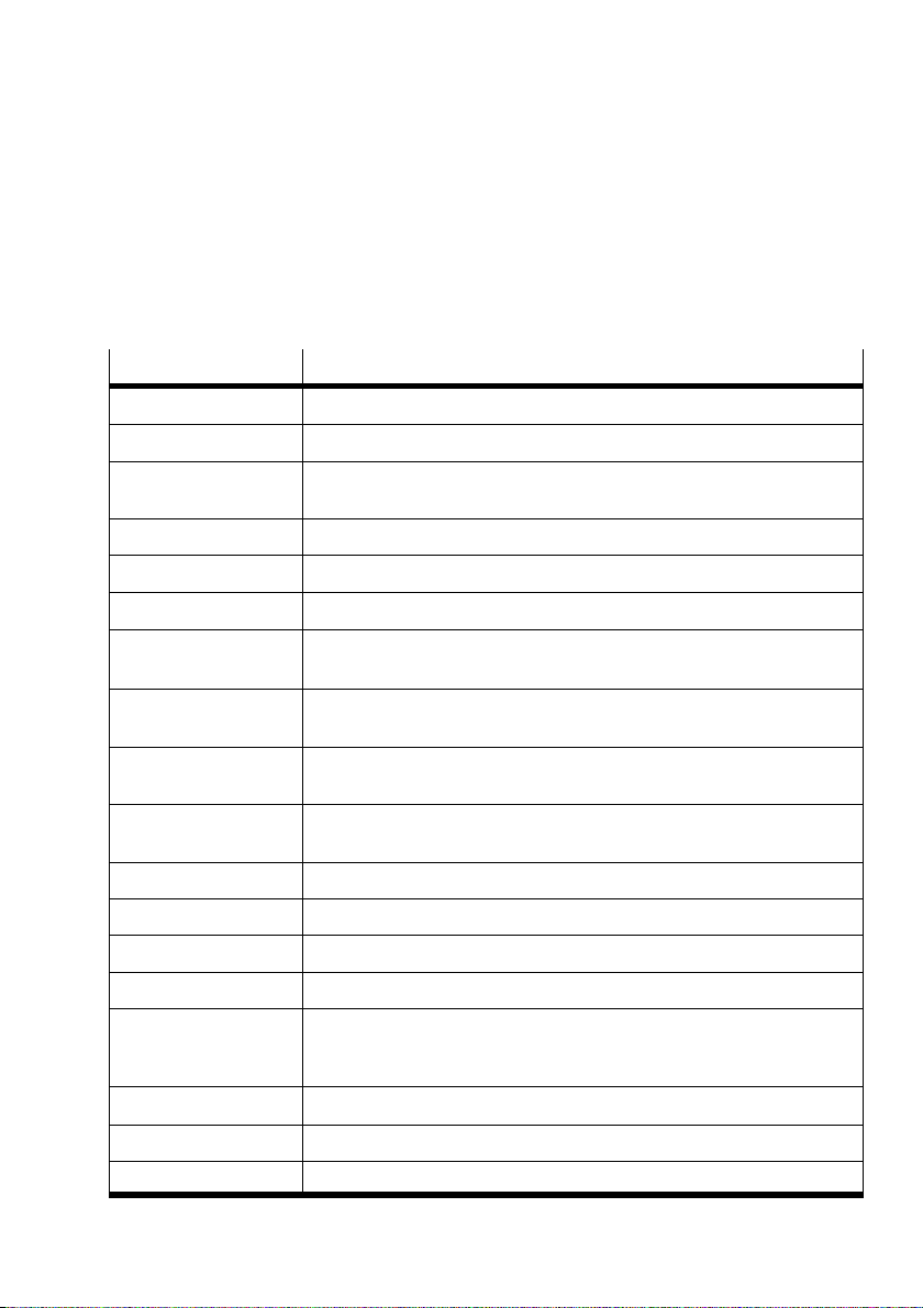
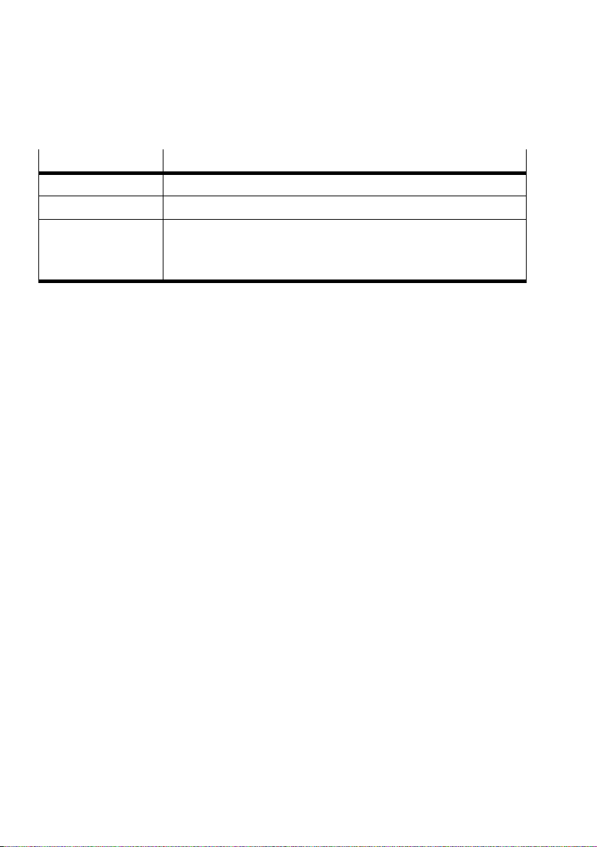
Glossary
The following product-specific terms and abbreviations are
used in this manual:
Term/abbreviation
Logic 0 Input or output provides 0 V (also LOW, FALSE or 0-signal).
Logic 1 Input or output provides 24 V (also HIGH, TRUE or 1-signal).
0xA0
A0
h
A Digital output
AB Output byte
Axis Motor controller, linear/rotative axis, motor and gear units
Axis connection Interface of the CPX-CM-HPP for connection of the motor controller via
CPX-FEC Front unit controller as CPX module. Controller which can be integrated
CPX-CEC-... CoDeSys controller as CPX module. Controller which can be integrated into
CPX module Collective term for the various modules which can be integrated into a
CPX terminal Complete system consisting of CPX modules.
E Digital input
I/Os Digital inputs and outputs
FE Functional earth
Bus node Provides the connection to specific fieldbuses. Transmits control signals to
Significance
Hexadecimal numbers are marked by a prefixed “0x” or by a lowered “h”.
Example: 0xA0 = A0h = 160 decimal.
CAN bus.
into the CPX terminal.
the CPX terminal.
CPXterminal.
the connected modules and monitors their functionality (as CPX module:
CPX bus node).
FHPP Festo Handling and Positioning Profile
Handheld CPX-MMI Handheld terminal for commissioning and service purposes
Parameters Parameters which must be set so that the system can be operated.
Festo CPX-CM-HPP-EN 2017-06b English
XV
Page 18
Contents and general instructions
Term/abbreviation Significance
Parameters Parameters which must be set so that the system can be operated.
RSB Record status byte
Controller Control of the CPX terminal and the CPX-CM-HPP is carried out through:
– a higher-order controller:
a controller that is connected to the CPX terminal via fieldbus
– CPX-FEC or: CPX-CEC-... an integrated controller in the CPX terminal
Tab. 0/3: Terms and abbreviations
XVI
Festo CPX-CM-HPP-EN 2017-06b English
Page 19

System summary
Chapter 1
System summary
1-1Festo CPX-CM-HPP-EN 2017-06b English
Page 20

1. System summary
Contents
1. System summary 1-1...............................................
1.1 The CPX-CM-HPP 1-3...............................................
1.1.1 Functions and key features 1-3................................
1.1.2 Tasks 1-3.................................................
1.2 Supported motor controllers 1-4......................................
1.3 Control options 1-5.................................................
1.4 System configurations 1-6...........................................
1.4.1 Autonomous automation solution 1-6..........................
1.4.2 Control of the CPX terminal through the higher-order controller 1-7..
1.4.3 Autonomous automation solution with communication
with ahigher-order controller 1-8..............................
1.5 Connection and display components 1-9...............................
1-2
Festo CPX-CM-HPP-EN 2017-06b English
Page 21

1. System summary
1.1 The CPX-CM-HPP
The CPX-CM-HPP is an interface for electric positioning and
handling axes in the Festo CPX system.
Programming of the CPX-CM-HPP is not required. The
following options are available for configuration:
–MMI
–FMT
– EDS file
– GSD file
– Programming software of the CPX front unit controller
1.1.1 Functions and key features
1.1.2 Tasks
Festo CPX-CM-HPP-EN 2017-06b English
The CPX-CM-HPP is designed for up to 4 axes. The axes are
connected at the front via the CAN bus interface (M9, 5-pin).
The motor controllers are configured with the Festo
Configuration Tool FCT.
The motor controllers are actuated by a higher-order
controller via CPX bus node or the integrated CPX-FEC or
CPX-CEC-... controller in the CPX terminal. The CPX-CM-HPP
merely forwards the I/O data. The Festo data profile FHPP is
used for the communication.
The CPX-CM-HPP takes over the following tasks:
– Transmission of control and status data between the
controller and the connected motor controllers
– Malfunction management
1-3
Page 22
1. System summary
1.2 Supported motor controllers
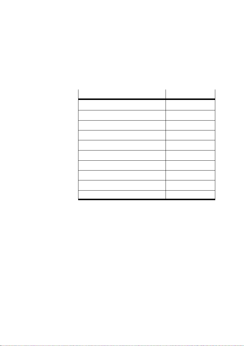
The CPX-CM-HPP supports the following motor controllers:
Motor controller
CMMS-AS –
CMMS-ST –
CMMP-AS –
Motor unit MTR-DCI-...-CO –
SFC-DC-…-CO –
SFC-LAC-…-CO –
CMMD-AS –
Planar surface gantry EXCM with controller –
Integrated drive EMCA-EC-...-CO –
Controller CMXH –
Tab. 1/4: Supported motor controllers
(as of March 2017)
Comment
1-4
Festo CPX-CM-HPP-EN 2017-06b English
Page 23
1. System summary
1.3 Control options
The CPX-CM-HPP can be controlled in two ways:
– Control through higher-order controller, using a CPX bus
node
or
– Control through front unit controller in the CPX terminal
The Festo data profile FHPP is used for communication
withthe controller (32 byte input and output data, 8 bytes
per axis).
You can find detailed information on the FHPP in the
applicable description documentation of the motor
controllers.
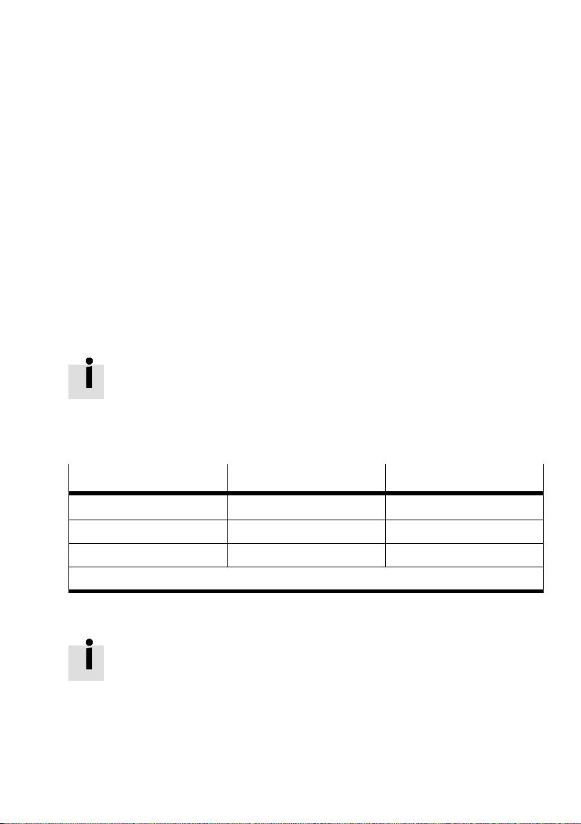
The following software versions of the CPX modules are
required to operate the CPX-CM-HPP:
CPX module
CPX-FB11 (DeviceNet) Revision 22 and above –
CPX-FB13 (PROFIBUS) Revision 23 and above –
CPX-FEC Revision 16 and above –
1)
Software version (SW) see product label
Required version
1)
Comment
Tab. 1/5: Required software versions as of September 2014)
Note the following for use of the CPX-CM-HPP:
– Deactivate the diagnostic byte for use of two CPX-CM-HPP
in one CPX terminal.
– Do not change the CAN bus setting Node ID: Default 1.
Festo CPX-CM-HPP-EN 2017-06b English
1-5
Page 24
1. System summary
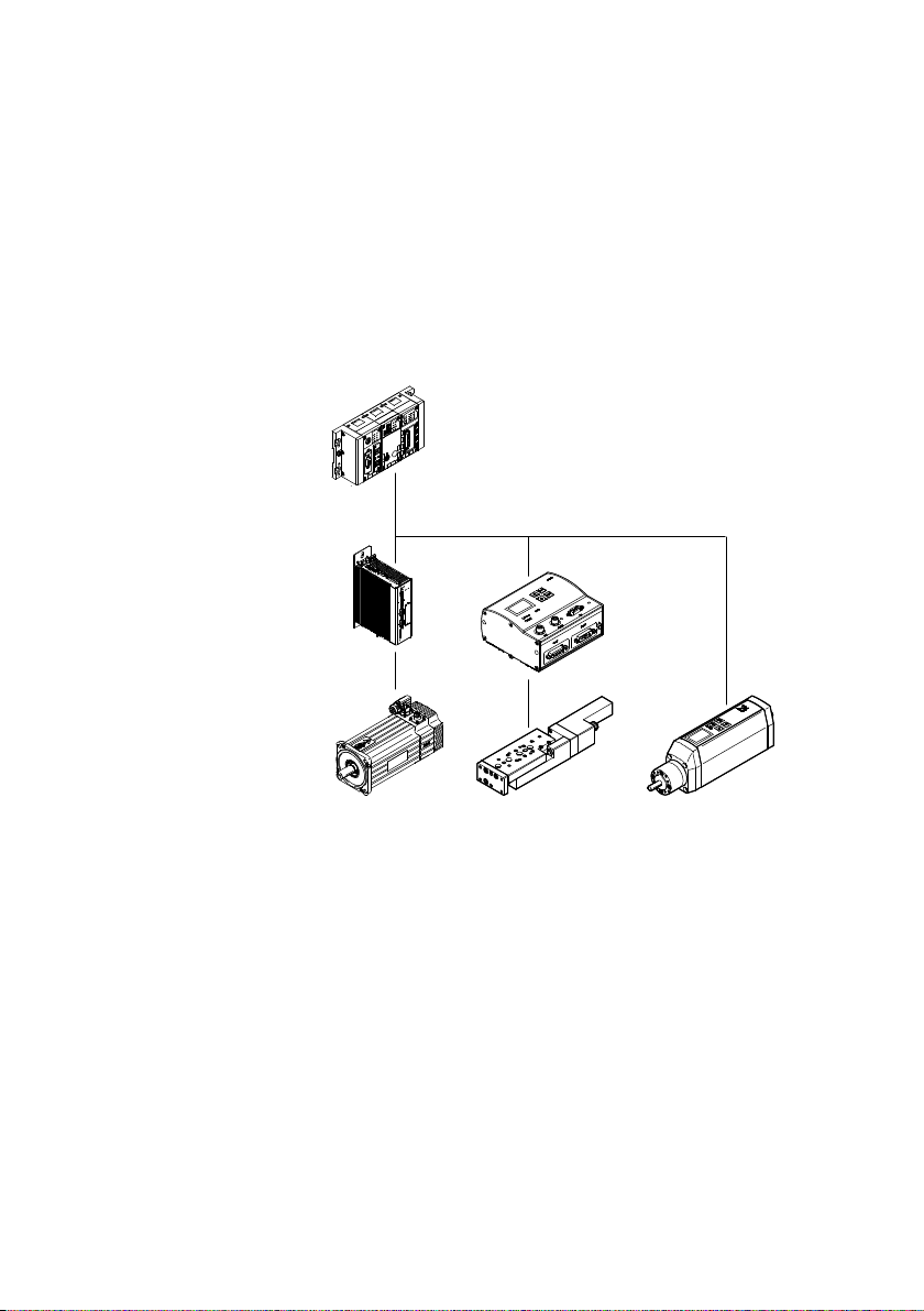
1.4 System configurations
1.4.1 Autonomous automation solution
1
CPX-Terminal with
CPX-FEC / CPX-CEC-...
and CPX-CM-HPP
1
2 CAN bus
3 CMMS
2
4 EMMS
5 SFC-DC
6 SLTE
7 MTR-DCI
Fig. 1/1: Autonomous automation solution with CPX terminal, CPX-FEC/CPX-CEC-... and
CPX-CM-HPP (example)
3
4
In this configuration, the sequence control of the
CPXterminal is taken over by the CPX-FEC/CPX-CEC-...
TheFesto data profile FHPP is used for the communication.
67
5
1-6
Festo CPX-CM-HPP-EN 2017-06b English
Page 25
1. System summary
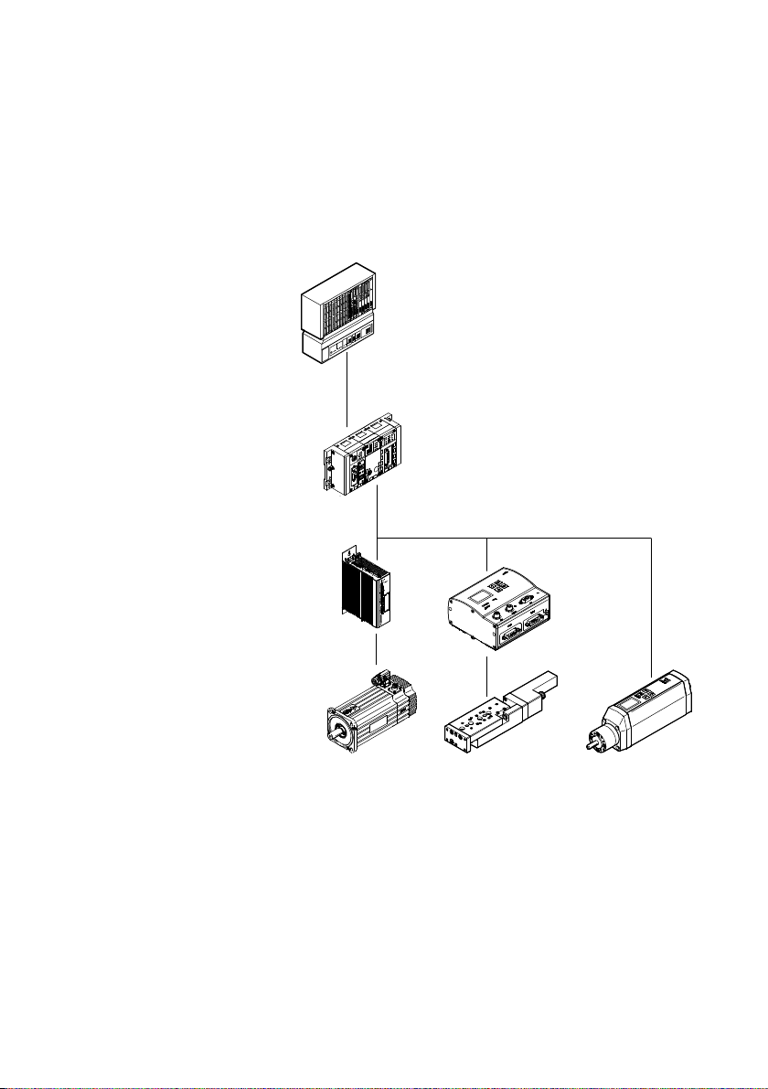
1.4.2 Control of the CPX terminal through the higher-order controller
1
Higher-order
controller
1
2 Fieldbus
3 CPX terminal with bus
node, e.g. CPX-FB13,
and CPX-CM-HPP
2
4 CAN bus
5 CMMS
6 EMMS
7 SFC-DC
3
4
8 SLTE
9 MTR-DCI
5
6
Fig. 1/2: Design of CPX terminal with higher-order controller (example)
In this configuration, the sequence control of the
CPXterminal is taken over by a higher-order controller.
TheFesto data profile FHPP is used for the communication.
7
89
Festo CPX-CM-HPP-EN 2017-06b English
1-7
Page 26
1. System summary
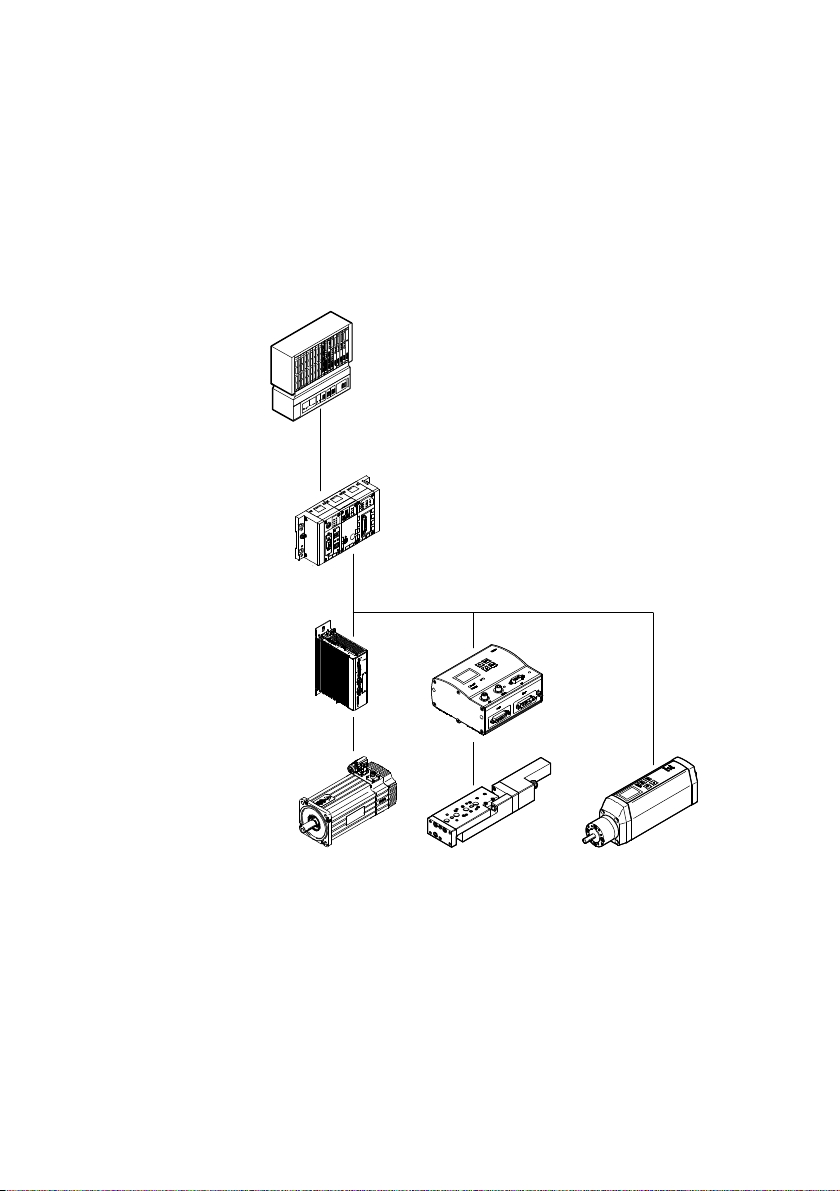
1.4.3 Autonomous automation solution with communication with
ahigher-order controller
1
Higher-order
controller
1
2 Fieldbus
3 CPX terminal with
CPX-FB13, CPX-FEC
and CPX-CM-HPP
2
4 CAN bus
5 CMMS
6 EMMS
7 SFC-DC
3
4
8 SLTE
9 MTR-DCI
5
6
Fig. 1/3: Design of an autonomous automation solution with communication with
ahigher-order controller (example)
In this configuration, the sequence control of the
CPXterminal is taken over by the CPX-FEC. The Festo data
profile FHPP is used for the communication.
1-8
7
89
Festo CPX-CM-HPP-EN 2017-06b English
Page 27
1. System summary
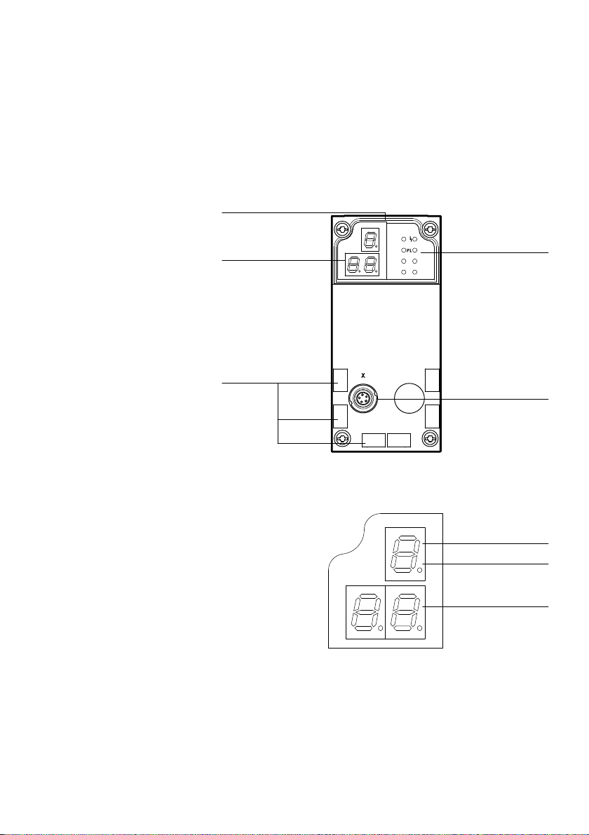
1.5 Connection and display components
The following connection and display components are found on the CPX-CM-HPP:
1 Status LEDs,
seeSection 4.4
5
2 X: Axis connection
4
3 Inscription labels
(accessories)
4 3-digit display,
seeSection 4.3
5 Product label,
seeside
Fig. 1/4: Connection and display components on the CPX-CM-HPP
3
6 1st position
(e.g. identifying letter
for parameters or
status type)
7 Point for separation
8 2nd and 3rd position
(e.g. value, stage or
status information)
1
2
6
7
8
Fig. 1/5: Display/7 segment display
Festo CPX-CM-HPP-EN 2017-06b English
1-9
Page 28

1. System summary
1-10
Festo CPX-CM-HPP-EN 2017-06b English
Page 29

Fitting and installation
Chapter 2
Fitting and installation
2-1Festo CPX-CM-HPP-EN 2017-06b English
Page 30

2. Fitting and installation
Contents
2. Fitting and installation 2-1..........................................
2.1 General instructions for installation 2-3................................
2.2 Dismantling and mounting 2-4.......................................
2.2.1 Dismounting 2-4...........................................
2.2.2 Mounting 2-5..............................................
2.3 Axis connection (CAN bus interface) 2-6................................
2.4 Connecting the CAN bus 2-7.........................................
2.4.1 CAN bus line 2-7...........................................
2.4.2 Terminating resistor 2-8.....................................
2-2
Festo CPX-CM-HPP-EN 2017-06b English
Page 31
2. Fitting and installation
2.1 General instructions for installation
Warning
Before carrying out installation and maintenance work,
switch off the following:
if applicable, the compressed air supply
operating voltage supply for the electronics/sensors
load voltage supply for the outputs/valves
In this way, you can avoid:
– uncontrolled movements of loose tubing lines
– unintended movements of the connected actuators
– undefined switching statuses of the electronics
Festo CPX-CM-HPP-EN 2017-06b English
Warning
The CPX-CM-HPP contains electrostatically sensitive
devices.
Therefore, do not touch any components.
Observe the handling specifications for electrostatically
sensitive devices.
They will help you avoid damage to the electronics.
Information about mounting of the CPX terminal can be found
in the CPX system description (CPX-SYS-...).
Information on mounting the components of the positioning
system can be found in the related components
documentation.
2-3
Page 32
2. Fitting and installation
2.2 Dismantling and mounting
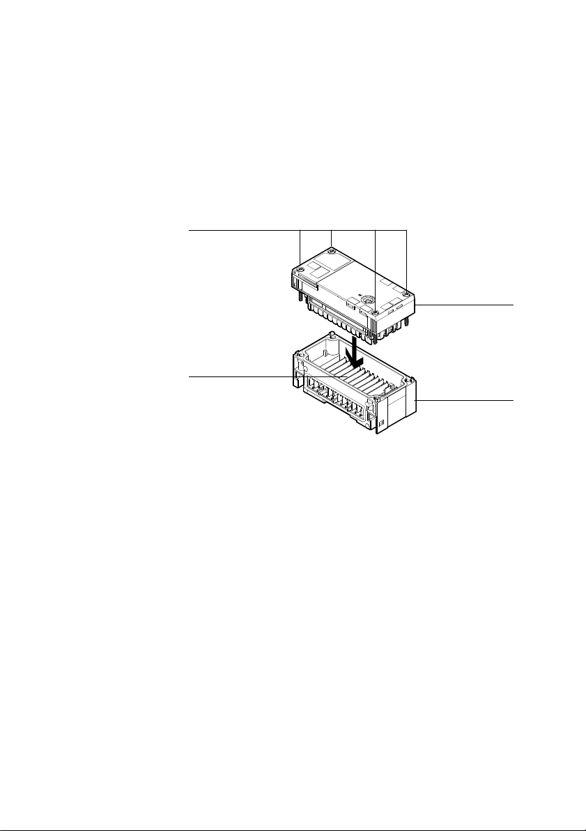
The CPX-CM-HPP is mounted in an interlinking block of the
CPX terminal (see Fig. 2/1).
1 CPX-CM-HPP
4
2 Interlinking block
3 Contact rails
4 Screws,
tightening torque
0.9... 1.1 Nm
3
Fig. 2/1: Dismounting/mounting the CPX-CM-HPP
2.2.1 Dismounting
Dismount the CPX-CM-HPP as follows:
1. Loosen the 4 screws of the CPX-CM-HPP.
2. Pull the CPX-CM-HPP carefully and without tilting away
from the contact rails of the interlinking block.
1
2
2-4
Festo CPX-CM-HPP-EN 2017-06b English
Page 33

2. Fitting and installation
2.2.2 Mounting
Mount the CPX-CM-HPP as follows:
1. Place the CPX-CM-HPP in the interlinking block. Make
sure that the slots with the terminals for electrical contact
on the bottom of the CPX-CM-HPP are positioned directly
above the contact rails.
2. Press the CPX-CM-HPP carefully and without tilting into
the interlinking block up to the stop.
3. Join the screws so that the self-cutting threads can be
used.
4. Tighten the screws by hand in diagonally opposite
sequence. Tightening torque 0.9 ... 1.1 Nm.
Festo CPX-CM-HPP-EN 2017-06b English
2-5
Page 34
2. Fitting and installation
2.3 Axis connection (CAN bus interface)
The motor controllers of the positioning system are
connected via the CAN bus to the axis connection of the
CPX-CM-HPP.
CAN bus parameters:
– Rate of transmission: 1 Mbit/s
– Data profile: FHPP
– Max. cable length: 30 m
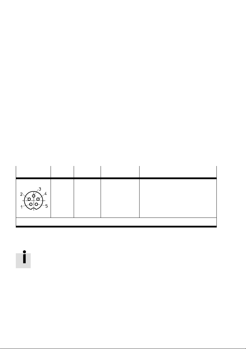
The axis connection of the CPX-CM-HPP is designed as
a5-pin M9 socket contact.
Bush M9
1) with use of a connecting cable with open end, e.g. NEBC-M9W5-K-5-N-LE3
Pin Signal Core colour
1
2
3
4
5
Housing
n.c.
n.c.
CAN_GND
CAN_H
CAN_L
Green
White
Brown
1)
Explanation
Not connected
Not connected
CAN Ground
CAN High
CAN Low
Tab. 2/6: Pin allocation of the CAN bus interface
The CPX-CM-HPP does not provide a power supply via the
CANbus interface to the CAN bus users.
2-6
Festo CPX-CM-HPP-EN 2017-06b English
Page 35
2. Fitting and installation
2.4 Connecting the CAN bus
2.4.1 CAN bus line
Note
Faulty installation and high transmission rates may cause
data transmission errors as a result of signal reflections
and attenuations.
Transmission errors can be caused by:
missing or incorrect terminating resistor
incorrect screened connection
branches
long distances
unsuitable cables
Festo CPX-CM-HPP-EN 2017-06b English
Use a Festo connecting cable with open end as a CAN bus
line between CPX-CM-HPP and the first motor controller,
e.g.NEBC-M9W5-K-5-N-LE3.
Use a twisted, screened 4-core cable as CAN bus line
between the motor controllers. A CAN bus plug is available
asan accessory to connect the motor controllers
(www.festo.com/catalogue).
When using the Festo CAN bus plug, a cable diameter of
5...8 or 7...10 mm is permitted.
Note
If the CPX terminal is mounted onto the moving part of
amachine, the CAN bus line on the moving part must be
provided with strain relief. Also observe the corresponding
regulations in EN60204 Part 1.
2-7
Page 36

2. Fitting and installation
2.4.2 Terminating resistor
A terminating resistor for the CAN bus is integrated at the
axis connection.
A can bus terminating resistor for 120 ohms must only be
installed at the other end of the CAN bus. Depending on the
actuator, this terminating resistor is integrated in the
actuator and activated with the DIL switch. If the actuator
does not have an integrated terminating resistor, it must be
connected manually between the signal CAN H (High) and
CAN L (Low).
2-8
Festo CPX-CM-HPP-EN 2017-06b English
Page 37

Commissioning
Chapter 3
Commissioning
3-1Festo CPX-CM-HPP-EN 2017-06b English
Page 38

3. Commissioning
Contents
3. Commissioning 3-1................................................
3.1 General instructions on commissioning 3-3.............................
3.2 Communication profile FHPP 3-4......................................
3.2.1 Overview of FHPP data structure 3-5...........................
3.3 Communication between CPX-CM-HPP and the motor controllers 3-9........
3.4 Commissioning 3-10.................................................
3.5 Parameterisation of the connected motor controllers with FCT 3-12...........
3.5.1 Prerequisite for commissioning motor controllers with FCT 3-12......
3.5.2 Commissioning motor controllers 3-12...........................
3.5.3 Specific settings for motor controllers CMMD-AS, CMMS-AS
and CMMS-ST 3-14..........................................
3.5.4 Specific settings for motor controller CMMP-AS 3-16...............
3.5.5 Specific settings for motor unit MTR-DCI--...-CO 3-17...............
3.5.6 Specific settings for motor controller SFC-DC-...-CO 3-18............
3.5.7 Specific settings for motor controller SFC-LAC-...-CO 3-19...........
3.5.8 Specific settings for planar surface gantry EXCM with controller 3-19..
3.5.9 Specific settings for integrated drive EMCA 3-20..................
3.5.10 Specific settings for controller CMXH 3-20........................
3.6 Configuration of the CPX-CM-HPP 3-21..................................
3.6.1 Configuration parameters 3-21.................................
3.6.2 Description Configuration parameters 3-22.......................
3.6.3 Other parameters: 3-25.......................................
3.6.4 Configuration with the MMI 3-26...............................
3.6.5 Configuration with CPX-FMT 3-28...............................
3.7 Force 3-30.........................................................
3-2
Festo CPX-CM-HPP-EN 2017-06b English
Page 39
3. Commissioning
3.1 General instructions on commissioning
Warning
Do not switch on the power supply and compressed air
until the entire system has been installed completely and
without errors.
Warning
Danger of collisions resulting in serious injuries due to
unintended actuator movements.
Be very careful when the axes are moving (e.g. when
teaching positions, jogging and homing).
Make sure that nobody enters the sphere of influence
ofthe drives or other connected actuators.
Information about commissioning the CPX terminal can be
found in the CPX system description (CPX-SYS-...).
Festo CPX-CM-HPP-EN 2017-06b English
Information on commissioning the components of the
positioning system, motor controller, motors and axes can be
found in the related components documentation.
3-3
Page 40

3. Commissioning
3.2 Communication profile FHPP
Festo has developed an optimised data profile, the
“FestoHandling and Positioning Profile (FHPP)” that is
tailored to handling and positioning tasks.
The FHPP enables uniform control and programming for the
various fieldbus systems and controllers from Festo.
In addition, it provides the user with uniform definitions
ofthe
– operating modes,
– I/O data structure,
– parameter objects,
– sequence control.
An overview of the I/O data structure can be found in
Section3.2.1.
3-4
You can find detailed information on the FHPP in the
applicable documentation of the motor controllers.
Festo CPX-CM-HPP-EN 2017-06b English
Page 41
3. Commissioning
3.2.1 Overview of FHPP data structure
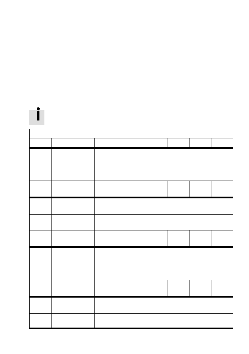
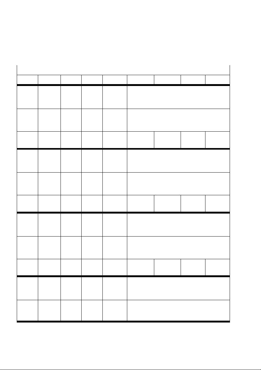
The following description of the telegram structure for
communication with the CPX-CM-HPP indicates the byte
allocation. Some items of the FHPP profile for the
CPX-CM-HPP deviate from the standard FHPP.
You can find detailed information on the FHPP in the
applicable documentation of the motor controllers.
Record selection operating mode
Byte 1 Byte 2 Byte 3 Byte 4 Byte 5 Byte 6 Byte 7 Byte 8
O-data
X-axis
I-data
X-axis
O-data
Y-axis
I-data
Y-axis
O-data
Z-axis
I-data
Z-axis
O-data
U-axis
I-data
U-axis
CCON CPOS Record no. Reserved Reserved
SCON SPOS Record no. RSB Actual position
Byte 9 Byte10Byte
11
CCON CPOS Record no. Reserved Reserved
SCON SPOS Record no. RSB Actual position
Byte17Byte18Byte
19
CCON CPOS Record no. Reserved Reserved
SCON SPOS Record no. RSB Actual position
Byte25Byte26Byte
27
CCON CPOS Record no. Reserved Reserved
SCON SPOS Record no. RSB Actual position
Byte
12
Byte
20
Byte
28
Byte13Byte14Byte15Byte
Byte21Byte22Byte23Byte
Byte29Byte30Byte31Byte
16
24
32
Festo CPX-CM-HPP-EN 2017-06b English
3-5
Page 42
3. Commissioning
Direct mode operating mode
Byte 1 Byte 2 Byte 3 Byte 4 Byte 5 Byte 6 Byte 7 Byte 8
O-data
X-axis
I-data
X-axis
O-data
Y-axis
I-data
Y-axis
O-data
Z-axis
I-data
Z-axis
CCON CPOS CDIR Setpoint
value 1
(speed)
SCON SPOS SDIR Actual
value 1
(speed)
Byte 9 Byte10Byte11Byte
12
CCON CPOS CDIR Setpoint
value 1
(speed)
SCON SPOS SDIR Actual
value 1
(speed)
Byte17Byte18Byte19Byte
20
CCON CPOS CDIR Setpoint
value 1
(speed)
SCON SPOS SDIR Actual
value 1
(speed)
Byte25Byte26Byte27Byte
28
Setpoint value 2
(position, force, torque,...)
Actual value 2
(actual position, actual force, actualtorque,...)
Byte
13
Setpoint value 2
(position, force, torque,...)
Actual value 2
(actual position, actual force, actual torque,...)
Byte
21
Setpoint value 2
(position, force, torque,...)
Actual value 2
(actual position, actual force, actual torque,...)
Byte
29
Byte
14
Byte
22
Byte
30
Byte 15Byte
16
Byte 23Byte
24
Byte 31Byte
32
O-data
U-axis
I-data
U-axis
3-6
CCON CPOS CDIR Setpoint
value 1
(speed)
SCON SPOS SDIR Actual
value 1
(speed)
Setpoint value 2
(position, force, torque,...)
Actual value 2
(actual position, actual force, actual torque,...)
Festo CPX-CM-HPP-EN 2017-06b English
Page 43
3. Commissioning
B7 B6 B5 B4 B3 B2 B1 B0
OPM2 OPM1 LOCK RESET BRAKE Stop ENABLE
Control bytes
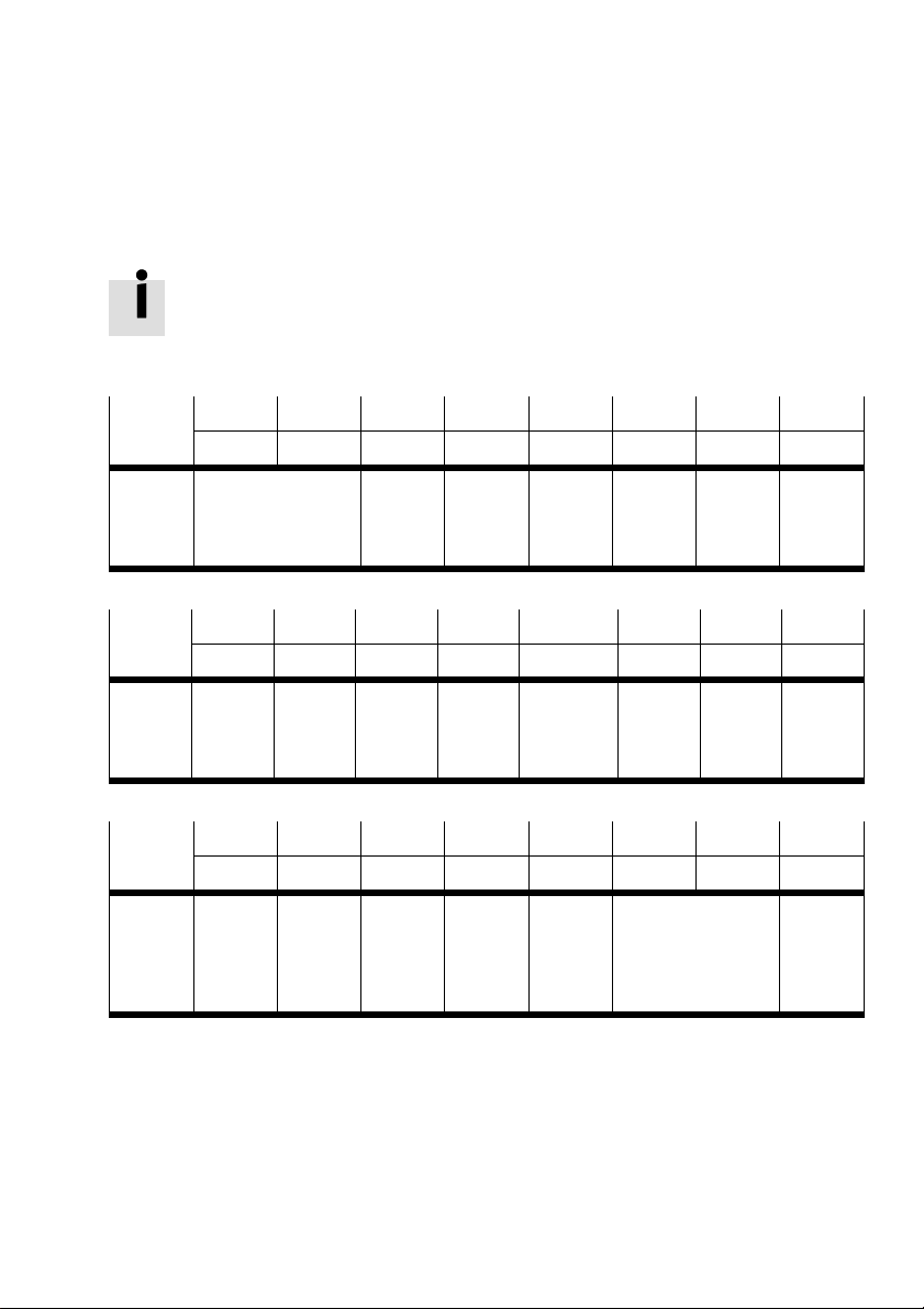
The functions of the individual bits may deviate from the
following definition depending on the drive. For the valid
definition, refer to the system description of the respective
drives.
CCON Operating mode
selection
B7 B6 B5 B4 B3 B2 B1 B0
CLEAR TEACH JOGN JOGP HOM START HALT
CPOS Delete
remain
ing path
B7 B6 B5 B4 B3 B2 B1 B0
FUNC FA ST XLIM CTOG CONT COM2 COM1 ABS
CDIR Execute
function
Precise
stop/
quick
stop
MMI
access
blocked
Teach
value
Stroke
limit
value
deactiv
ated
Jog
negative
Toggle
bit
tracking
mode
Acknow
ledge
mal
function
Jog
positive
Tracking
mode
Release
brake
Start
homing
Control mode
(Position, force,
torque, speed)
Stop Enable
Start
posi
tioning
task
drive
Stop
Abso
lute/
Relative
Festo CPX-CM-HPP-EN 2017-06b English
3-7
Page 44
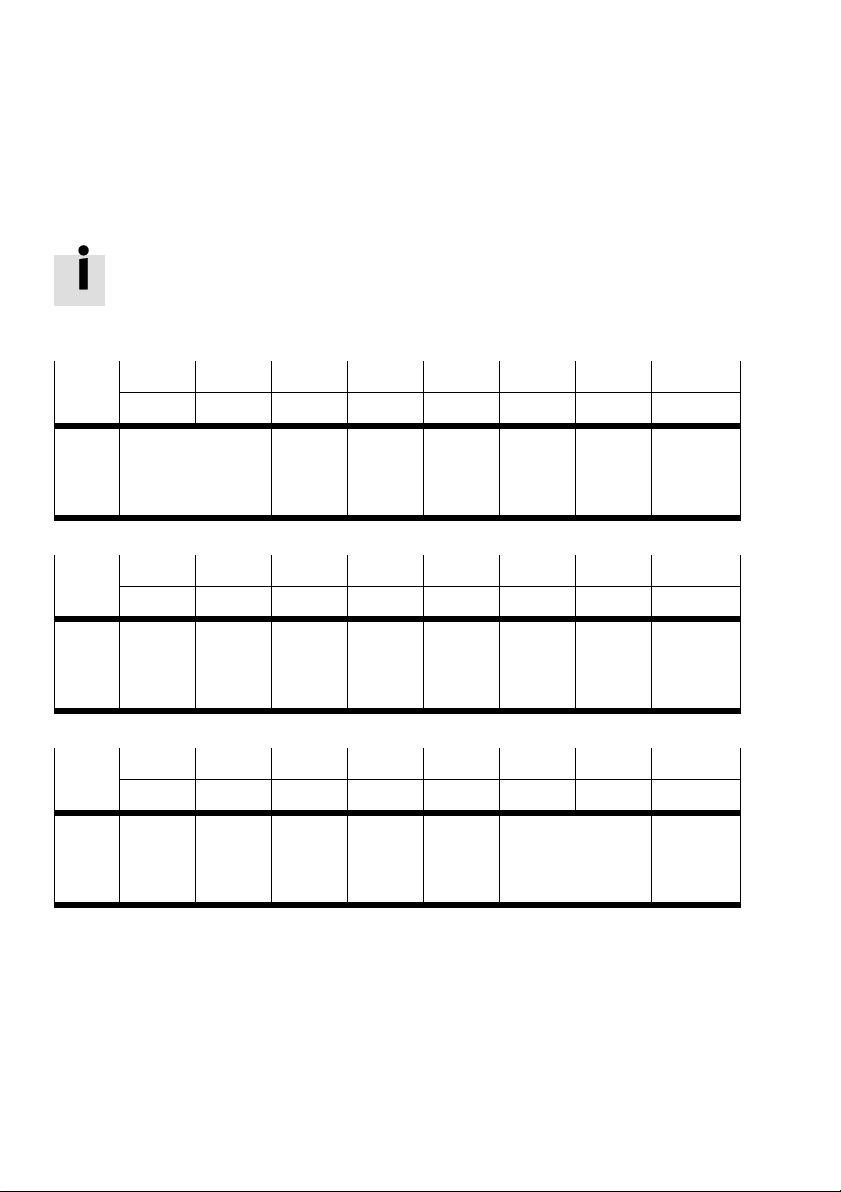
3. Commissioning
B7 B6 B5 B4 B3 B2 B1 B0
OPM2 OPM1 LOCK 24VL FAULT WARN OPEN ENABLED
Status bytes
The functions of the individual bits may deviate from the
following definition depending on the drive. For the valid
definition, refer to the system description of the respective
drives.
SCON Operating mode
feedback
B7 B6 B5 B4 B3 B2 B1 B0
REF STILL DEV MOV TEACH MC ACK HALT
SPOS Drive
homed
Stand
still
monitor
ing
B7 B6 B5 B4 B3 B2 B1 B0
FUNC FA ST XLIM VLIM CONT COM2 COM1 ABS
SDIR Function
is
executed
Precise
stop/
quick
stop
Master
control
FCT/
MMI
Follow
ing error
Stroke
limit
reached
Load
voltage
is
applied
Axis is
moving
Speed
limit
reached
Mal
function
Acknow
ledge
teaching
Tracking
mode
Warning Opera
Motion
com
plete
Control mode
feedback
(Position, force,
torque, speed)
tion
enabled
Acknow
ledge
start
Drive
enabled
Stop
Absolute/
Relative
3-8
Festo CPX-CM-HPP-EN 2017-06b English
Page 45
3. Commissioning
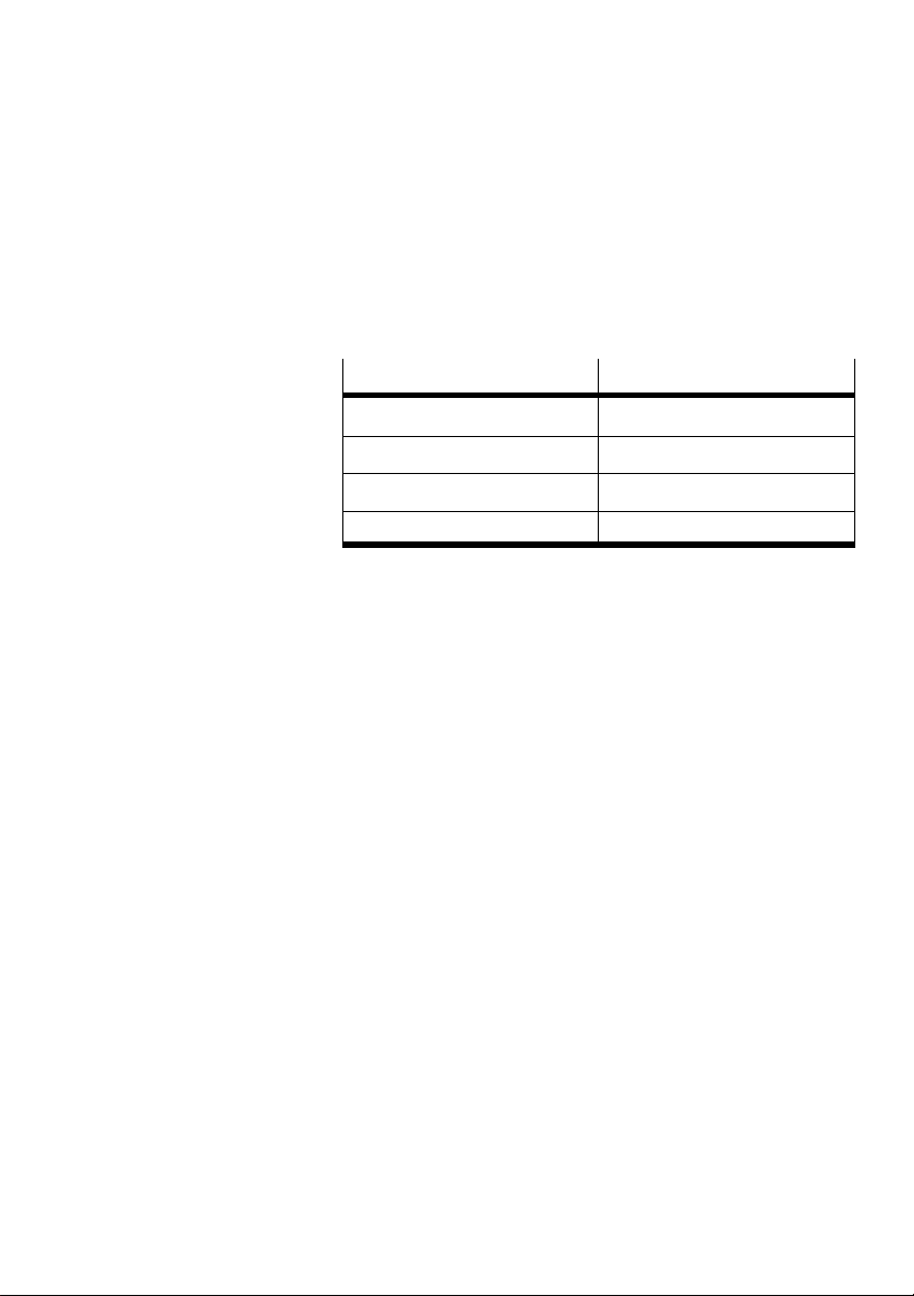
3.3 Communication between CPX-CM-HPP and the motor controllers
Communication between CPX-CM-HPP and the motor
controllers takes place over the following interface:
Parameters
Interface CANopen
Data profile FHPP
Bit rate 1000 kBit/s or 1 MBit/s
CAN address 2...9
Settings
Tab. 3/1: Parameters of the interface
Festo CPX-CM-HPP-EN 2017-06b English
3-9
Page 46
3. Commissioning
3.4 Commissioning
1. First, activate the drives as individual axes via the FCT
with the relevant plug-in. Observe the required settings
for the communication via CAN bus (see Chapter 3.5).
2. Configure the CPX-CM-HPP according to the drives
(drivetype, CAN address, data format, see Chapter 3.6).
Adjust the start mode so that the system starts with the
stored parameters (see CPX system description
CPX-SYS-...).
3. Switch the CPX terminal off.
4. Connect the CPX-CM-HPP with the drives via a CAN bus
cable (see www.festo.com/catalogue). Make sure that the
bus terminal is activated at the last user on the drive side.
5. Switch the CPX terminal on.
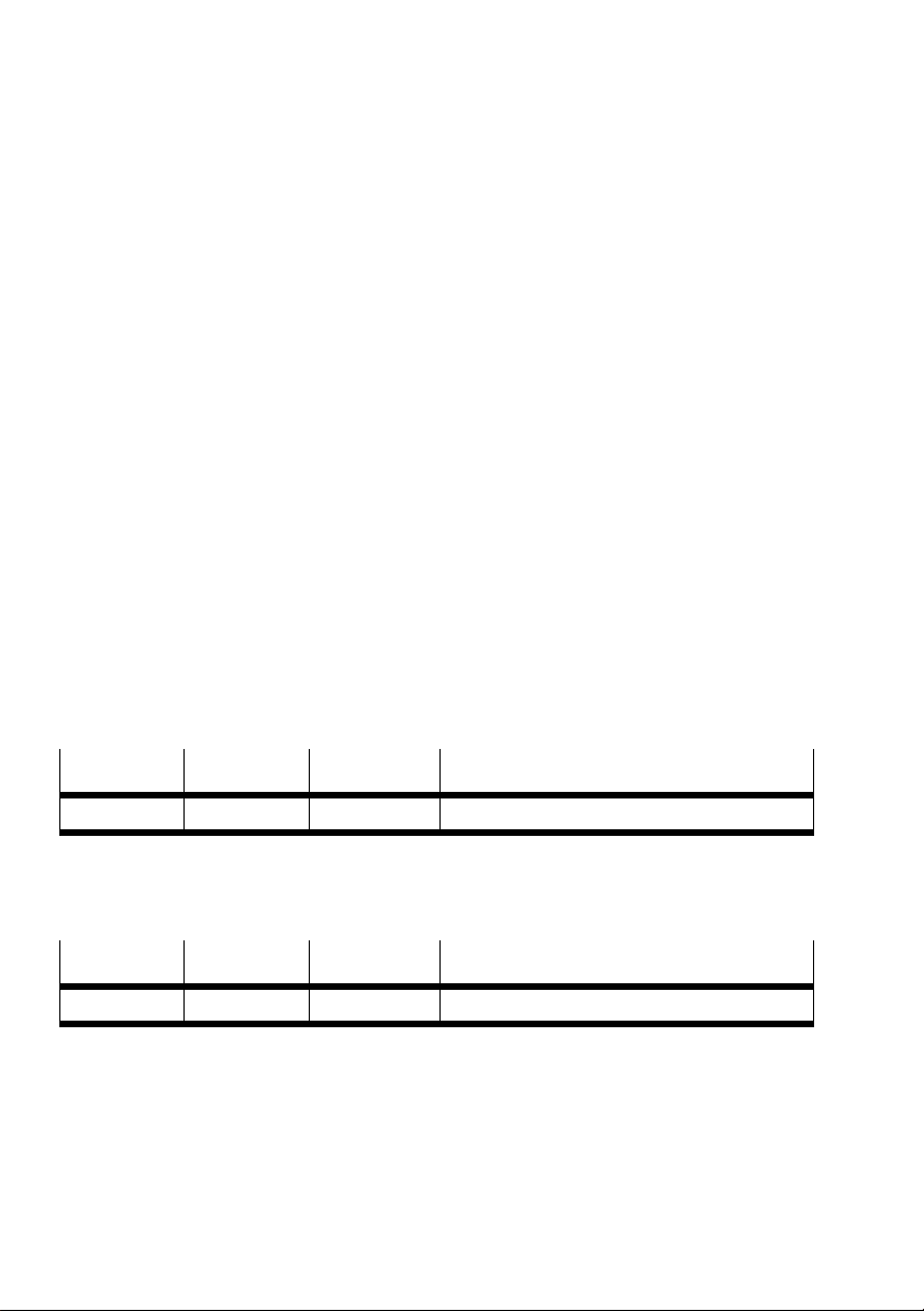
The three-digit 7-segment display (see Fig. 1/5) shows
the firmware design, e.g. Version 1.22:
1st position
1 2 2 Firmware Design 1.22
2nd position 3rd position Significance
The CPX-CM-HPP starts the initialisation of the drives,
e.g.with axis 1:
1st position
1 i n Initialisation of axis 1
2nd position 3rd position Significance
After the initialisation has been completed correctly, all
motor controllers will have status S0 and be ready for
operation.
3-10
Festo CPX-CM-HPP-EN 2017-06b English
Page 47
3. Commissioning
Error during initialisation
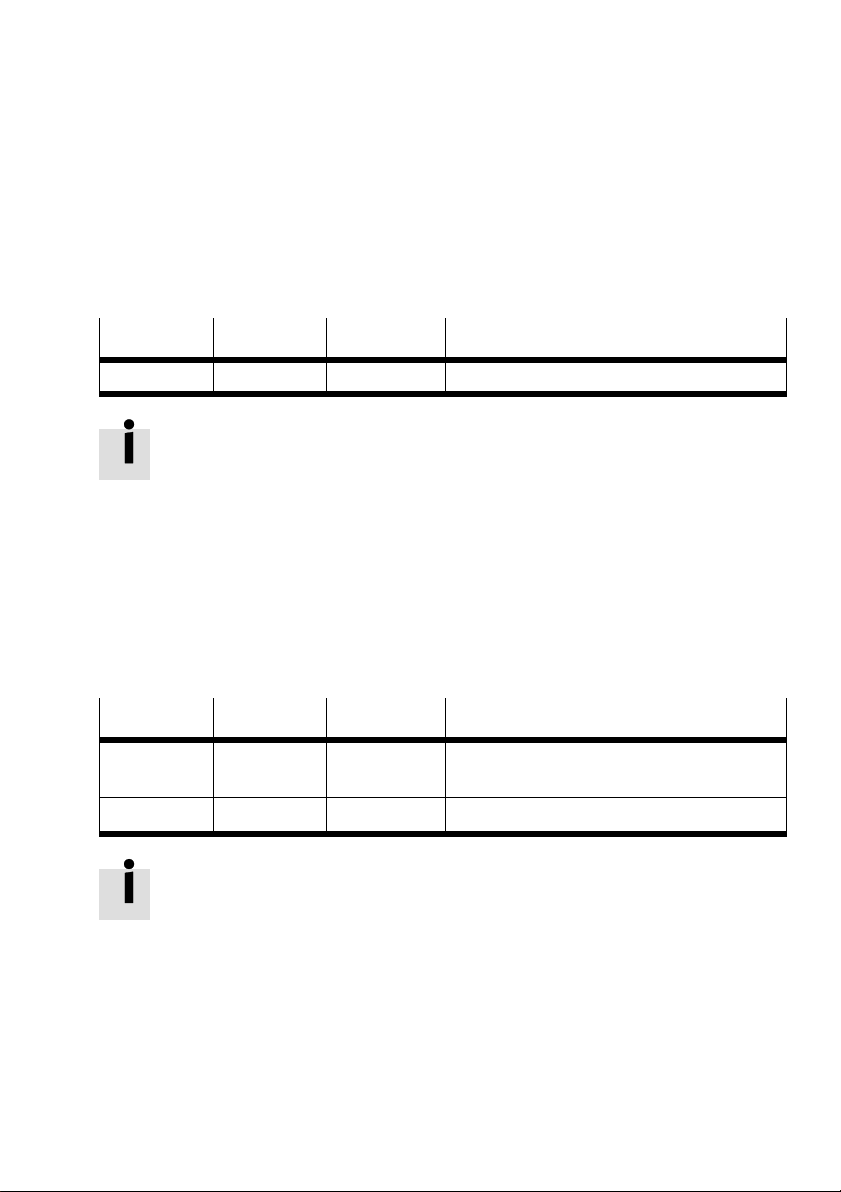
In the event of errors, the initialisation will stop at the faulty
axis. The error number is displayed continuously, e.g.
1st position
4 E (= error) 1 Axis 4 shows Error 1
2nd position 3rd position Significance
The initialisation will not continue until the error has
beeneliminated. For an overview of error numbers,
seeChapter4.2.3.
Error after initialisation
Errors that occur during operation are shown with an
alternating display. First, the error type is shown (error or
warning), followed by the error number. The duration of the
display is approximately 0.5 s each. The example below
shows the display for Error 44 on Axis 1:
1st position
1 E (= error)
1 4 4 Axis 1 shows Error 44
2nd position 3rd position Significance
Axis 1 shows error type “Error” or “Warning”
u (= Warning)
For an overview of error numbers, see Chapter 4.2.3.
Festo CPX-CM-HPP-EN 2017-06b English
3-11
Page 48
3. Commissioning
3.5 Parameterisation of the connected motor controllers with FCT
The following information takes into account only a general
approach for commissioning motor controllers and the
specific settings of the motor controllers for use in
positioning systems with CPX-CM-HPP. Information on other
settings can be found in the documentation and online help
for the respective motor controller.
3.5.1 Prerequisite for commissioning motor controllers with FCT
The following software packages and accessories are
required for commissioning motor controllers:
– PC with FCT software and relevant plug-ins for the motor
controllers
– Programming cable to connect the motor controllers
tothe PC, including special connections depending on
the PC
– System descriptions of the relevant devices
3.5.2 Commissioning motor controllers
Note
Carry out the following instructions for each motor
controller.
1. Connect the PC and the motor controller with a serial
programming cable.
2. Start the FCT software and follow the instructions in the
FCT and in the operating instructions of the respective
motor controller.
3. Make sure that the limit switches (if installed) function
properly.
3-12
Festo CPX-CM-HPP-EN 2017-06b English
Page 49

3. Commissioning
4. Check the following parameters
– Maximum travel
– Maximum travel speed
– Maximum acceleration or deceleration
– Transmission ratio for position and speed
– Software limit switch
– Type of reference travel
5. Edit the travel record table if you want to operate the
drive in record selection mode.
6. Save your settings in the controller (Download -> Save)
and in the project (Save).
The following chapters describe the specific parameters for
the relevant drives for the operation with CPX-CM-HPP.
Festo CPX-CM-HPP-EN 2017-06b English
3-13
Page 50
3. Commissioning
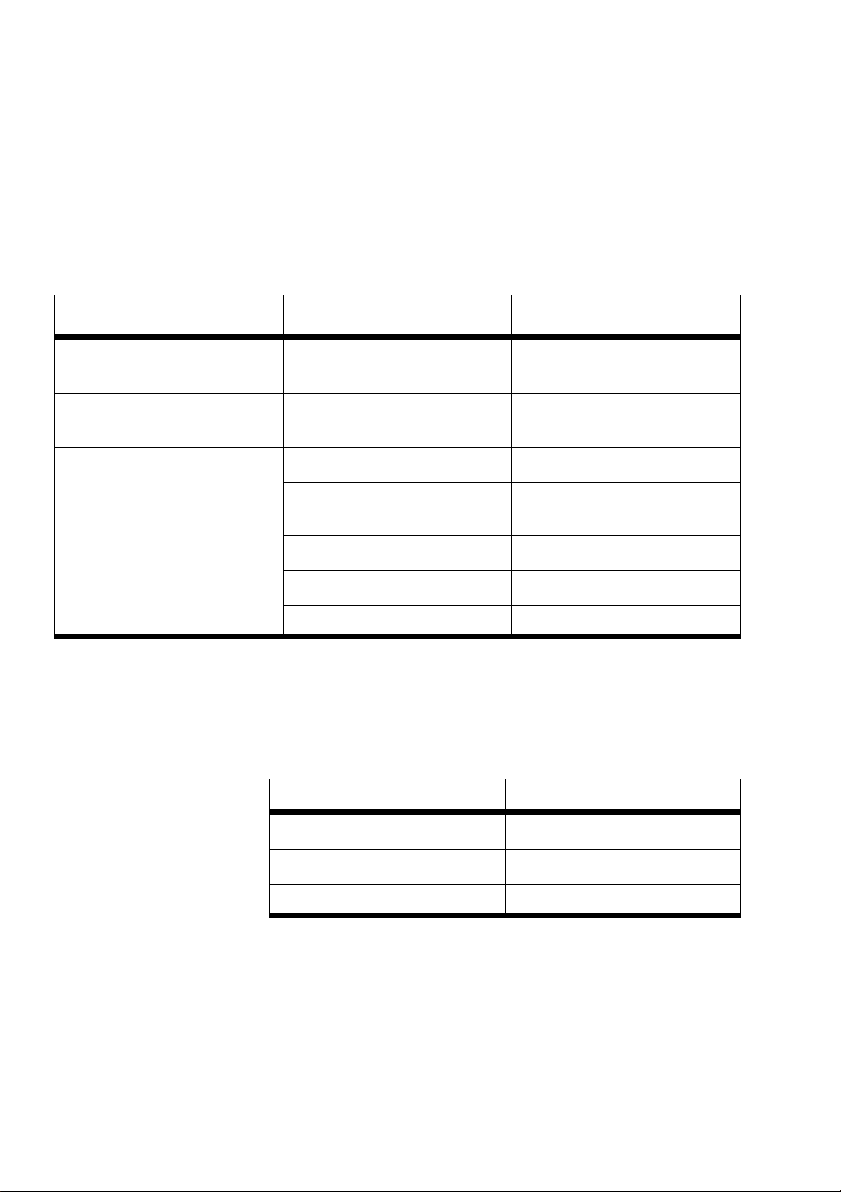
3.5.3 Specific settings for motor controllers CMMD-AS, CMMS-AS and CMMS-ST
Menu/Tab Parameters Value
[Application data]
[Operatingmodeselection]
[Controller] [Fieldbus]
[Interfaceparameter]
[Controller] [Fieldbus]
[Factorgroup]
Control interface CANopen
Data profile FHPP
Used Activated
Unit mm for linear axes
Exponent Position 10
Exponent Speed 10
Exponent Acceleration 10
° for rotative axes
-3
-3
-3
Tab. 3/2: Specific settings for motor controllers CMMD-AS, CMMS-AS and CMMS-ST
Enter the following settings with the DIL switches of the
motor controllers:
Parameters
Bus termination On/Off
Bit rate 1000 kBit/s
CAN address 2...9
Settings
3-14
Tab. 3/3: Settings for motor controllers CMMD-AS,
CMMS-AS and CMMS-ST
Festo CPX-CM-HPP-EN 2017-06b English
Page 51

3. Commissioning
CAN address with CMMD-AS:
The setting for the CAN address of the first controller is
entered in CMMD-AS. The CAN address of the first controller
+ 1 is automatically assigned to the second controller.
When the CMMD-AS is selected, only one controller of the
CMMD-AS is assigned to an axis. When the second controller
of the CMMD-AS must also be assigned to an axis, a CMMD
must also be assigned to this axis.
For more information, refer to the documentation of the
motor controllers.
Festo CPX-CM-HPP-EN 2017-06b English
3-15
Page 52
3. Commissioning
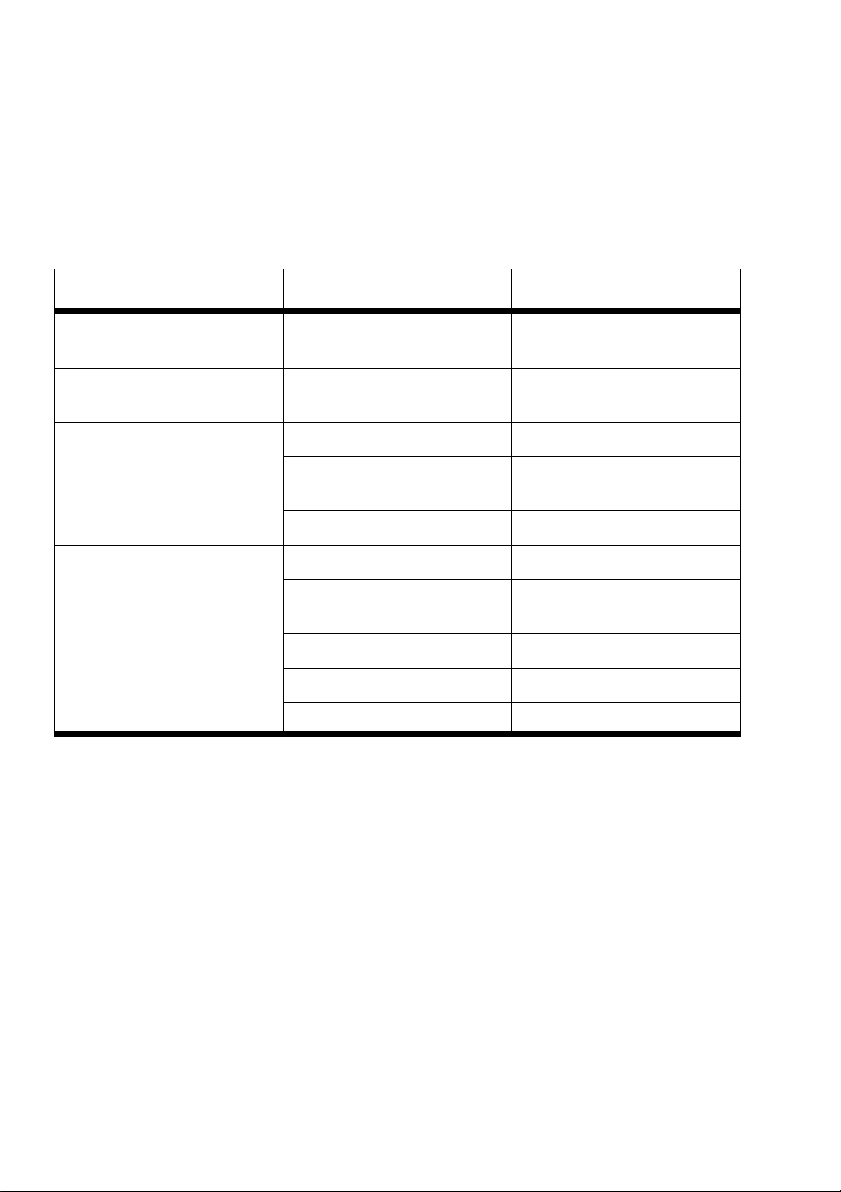
3.5.4 Specific settings for motor controller CMMP-AS
Menu/Tab Parameters Value
[Application data]
[Operatingmodeselection]
[Controller] Enable logic
[Controller] [Fieldbus]
[Operating parameter]
[Controller] [Fieldbus]
[Factorgroup]
Control interface CANopen
Enabled with
Bit rate 1000 kBit/s
Node number CAN address of the axis,
Protocol Festo FHPP
Used Activated
Unit mm for linear axes
Exponent Position 10
Exponent Speed 10
Exponent Acceleration 10
Tab. 3/4: Specific settings for motor controller CMMP-AS
DIN5 and Fieldbus
seeTab. 3/1
° for rotative axes
-3
-3
-3
3-16
Festo CPX-CM-HPP-EN 2017-06b English
Page 53
3. Commissioning
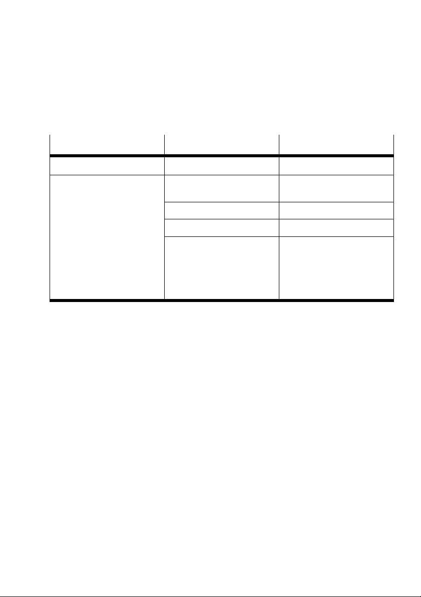
3.5.5 Specific settings for motor unit MTR-DCI--...-CO
Menu/Tab Parameters Value
[Configuration] Motor type MTR-DCI-...-CO
[Motor] [Control interface]
[Interface parameter]
CAN address CAN address of the axis,
Bit rate 1 Mbit/s
Data profile FHPP
Supply voltage Internal
Tab. 3/5: Specific settings for motor unit MTR-DCI-...-CO
seeTab. 3/1
With the “external” option, an
external supply voltage must
be connected at the CAN bus
plug, see system description
ofmotor unit MTR-DCI.
Festo CPX-CM-HPP-EN 2017-06b English
3-17
Page 54
3. Commissioning
3.5.6 Specific settings for motor controller SFC-DC-...-CO
Menu/Tab Parameters Value
[Configuration] Controller type SFC-DC-...-CO
[Controller] [Interface]
[Interfaceparameter]
CAN address CAN address of the axis,
seeTab. 3/1
Bit rate 1 Mbit/s
Data profile FHPP
Supply voltage Internal
With the “external” option, an
external supply voltage must
be connected at the CAN bus
plug, see system description of
motor controller.
Tab. 3/6: Specific settings for motor controller SFC-DC-...-CO
3-18
Festo CPX-CM-HPP-EN 2017-06b English
Page 55
3. Commissioning
3.5.7 Specific settings for motor controller SFC-LAC-...-CO
Menu/Tab Parameters Value
[Configuration] Controller type SFC-LAC-...-CO (CANopen)
[Controller] [Interface] CAN address CAN address of the axis,
Bit rate 1 Mbit/s
Data profile FHPP
Supply voltage With the “external” option, an
seeTab. 3/1
external supply voltage must
be connected at the CAN bus
plug, see system description of
motor controller.
Tab. 3/7: Specific settings for motor controller SFC-LAC-...-CO
3.5.8 Specific settings for planar surface gantry EXCM with controller
Menu/Tab Parameters Value
[Configuration] Controller type EXCM
[Controller] CAN address CAN address of the axis,
Bit rate 1 Mbit/s
Data profile FHPP
seeTab. 3/1
Tab. 3/8: Specific settings for planar surface gantry EXCM with controller
Festo CPX-CM-HPP-EN 2017-06b English
3-19
Page 56
3. Commissioning
3.5.9 Specific settings for integrated drive EMCA
Menu/Tab Parameters Value
[Configuration] Controller type EMCA
[Controller] CAN address CAN address of the axis,
Bit rate 1 Mbit/s
Data profile FHPP
seeTab. 3/1
Tab. 3/9: Specific settings for integrated drive EMCA
3.5.10 Specific settings for controller CMXH
Menu/Tab Parameters Value
[Configuration] Controller type CMXH
[Controller] CAN address CAN address of the axis,
Bit rate 1 Mbit/s
Data profile FHPP
Tab. 3/10: Specific settings for controller CMXH
seeTab. 3/1
3-20
Festo CPX-CM-HPP-EN 2017-06b English
Page 57
3. Commissioning
3.6 Configuration of the CPX-CM-HPP
3.6.1 Configuration parameters
For each module, 64 bytes are reserved for module
parameters that can be entered in the system table of
theCPX terminal. Function number 4828+m*64+0...63
(m=Module number in the CPX terminal).
Function number
4828 +m*64+6
4828+m*64+7 Node ID
4828+m*64+8 Format
4828 +m*64+9 Axis 2 Axis type
4828 +m*64+10 Node ID
4828 +m*64+11 Format
4828 +m*64+12 Axis 3 Axis type
4828 +m*64+13 Node ID
4828 +m*64+14 Format
4828 +m*64+15 Axis 4 Axis type
4828 +m*64+16 Node ID
4828 +m*64+17 Format
1) No gaps are permitted in the list. Axis type = “No Axis” is the end
of the list.
Parameter entry
Axis 1
Axis type
1)
1)
1)
1)
Tab. 3/11: Function number 4828 – Configuration
parameter
Festo CPX-CM-HPP-EN 2017-06b English
The configuration parameters are stored in the EEPROM of
the CPX-CM-HPP. The Axis type and Node ID parameters are
not effective until the next restart. The stored configuration
3-21
Page 58
3. Commissioning
parameters are loaded as “Default Parameters” at the next
start-up when the system parameter “System starts with
default parameter” is selected in the CPX fieldbus node or
the CPX-FEC.
3.6.2 Description Configuration parameters
Axis type
Value Significance
0 No Axis (axis not present)
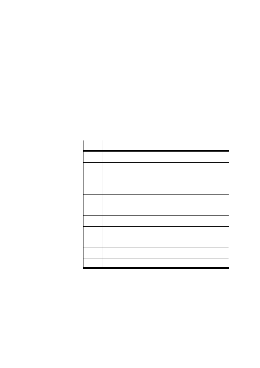
1 Motor controller CMMP-AS
2 Motor controller CMMS-AS
3 Motor controller CMMS-ST
3-22
4 Motor unit MTR-DCI-...-CO
5 Motor controller SFC-DC-...-CO
6 Motor controller SFC-LAC-...-CO
7 Planar surface gantry EXCM with controller
8 Motor controller CMMD-AS
9 Integrated drive EMCA
10 Controller CMXH
Tab. 3/12: Configuration parameters axis type
Node ID
CAN bus address of the motor controller
Value range: from 2 to 9
Festo CPX-CM-HPP-EN 2017-06b English
Page 59
3. Commissioning
Format
Input and output format of the position value
Valid for:
– Actual position
– Setpoint position in direct operation
Warning
Danger of personal injury and material damage.
In the event of incorrect settings for format specifications,
the setpoint positions of the actual positions may deviate.
Check the format specifications carefully.
Festo CPX-CM-HPP-EN 2017-06b English
Value
0 32 bit [Ink] For motor controller CMMx-xx only:
1 32 bit [μm] For motor unit MTR-DCI and motor
Format Significance
Original 32 bit Long Integer from motor
controller. When the factor group for
motor controller CMMx-xx is used, this
32bit value represents the path (e.g. μm)
depending on the resolution (e.g. 10
controller SFC-xx only:
The 32 bit position value is converted to
[μm] or [1/1000 °].
-3
).
3-23
Page 60
3. Commissioning
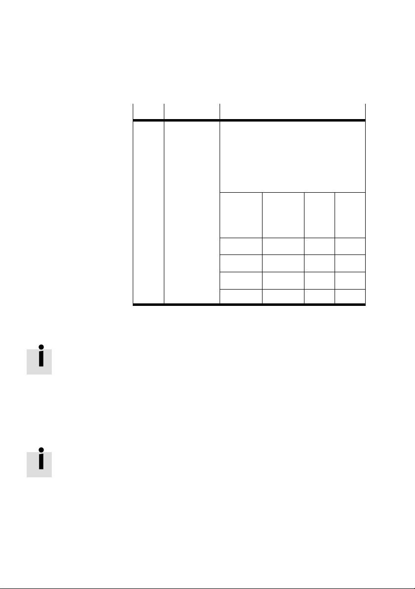
Value SignificanceFormat
2 VK/NK [mm] When a 16 bit controller is used,
e.g.CPX-FEC:
With MTR-DCI and SFC-xx, the position
value is first converted to [μm] or
[1/1000°] and then divided into value
before comma (VK) and value after
comma (NK).
Position
value
[μm] or
[1/1000 °]
245987 245.987 245 987
1234034 1234.034 1234 34
–200065 –200.065 –200 65
–345 –0.345 0 –345
Position
value
[mm] or
[°]
VK NK
Tab. 3/13: Configuration parameter format
Two values are used when a controller with an address range
> 65536 is used. A conversion to hexadecimal values is
required, see example below:
245987 = 0x3C0E3
Byte 4,5 (FHPP): 0xC0E3
Byte 6,7 (FHPP): 0x0003
A conversion is not required when a higher-order fieldbus
master and double-values are used.
3-24
When a Profibus controller is used, it must be ensured that
the bytes are transmitted correctly. The bytes may need to be
rotated.
Festo CPX-CM-HPP-EN 2017-06b English
Page 61
3. Commissioning
3.6.3 Other parameters:
Function
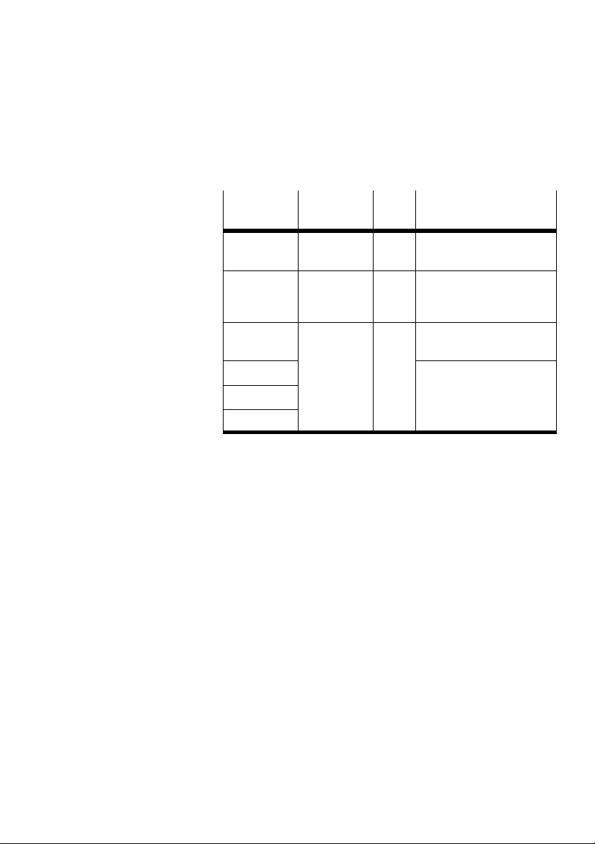
Parameters Value Comment
number
16+16*m+0 Module code 175 Entry in the CPX system
16+16*m+13 Version
number
784+m*4+0 Serial
number
784+m*4+1 The bytes 1...3 contain one
784+m*4+2
784+m*4+3
table.
0 ...
Indicates the version of the
255
module according to the
product label.
Byte 0: Contains the year
and month of the series.
digit of the serial number
per nibble (BCD encoded).
Tab. 3/14: Other parameters
Festo CPX-CM-HPP-EN 2017-06b English
3-25
Page 62

3. Commissioning
3.6.4 Configuration with the MMI
The configuration with the MMI is not available for the
following products:
CMMD-AS, CMXH, EMCA, EXCM.
Requirements
If you are using a system structure with a fieldbus slave as
CPX master:
Set the parameter “System start” (path: “CPX
Terminal/System parameters/System start”) once
to“Saved parameters”.
When the parameter “System start” is set to
“Default-Parameter”, the default parameters will be loaded.
The default parameters may deviate from the current system
configuration.
3-26
Configuration
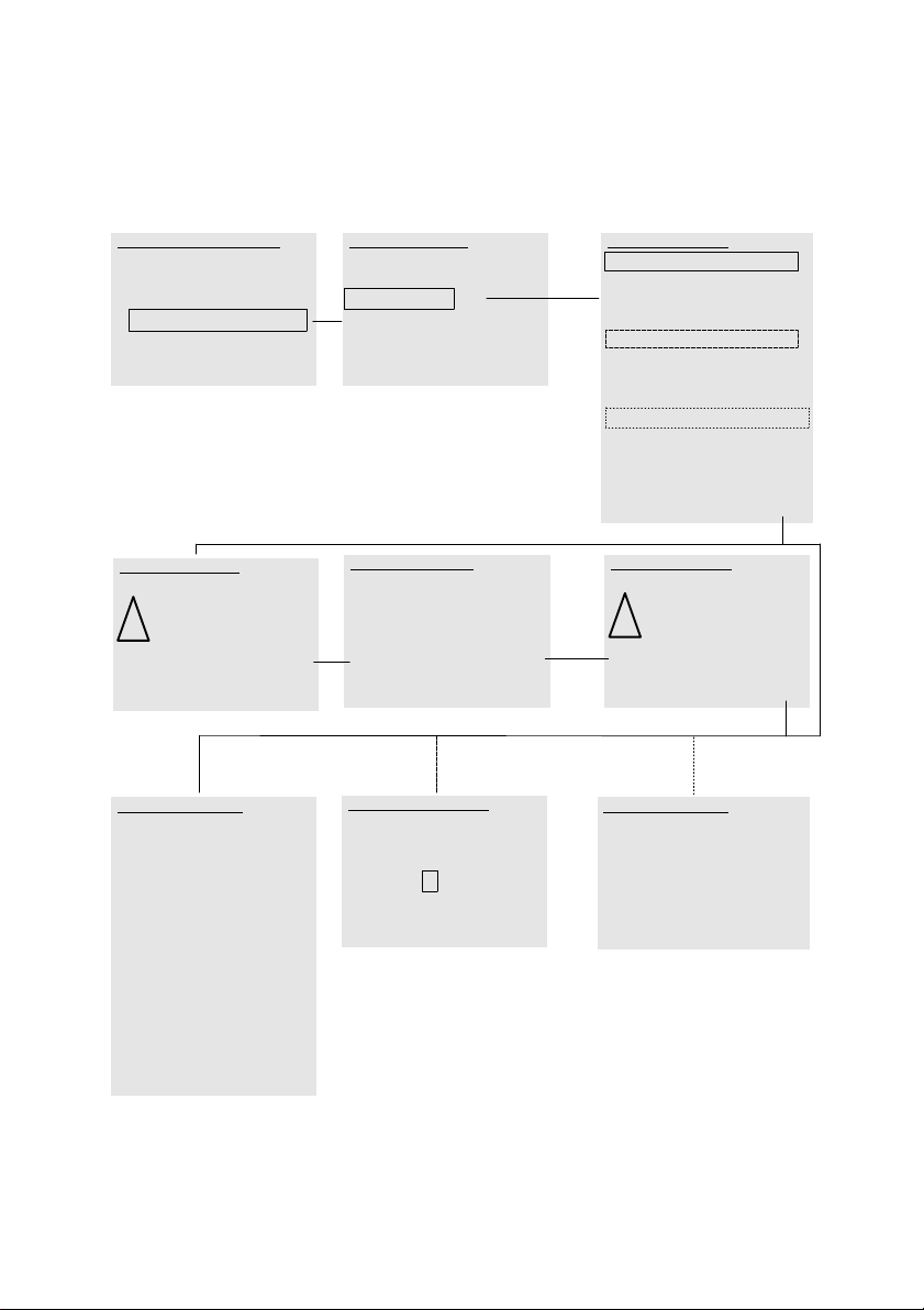
The configuration parameters of the CPX-CM-HPP are
displayed and revised in the [Parameter] menu.
For a description of possible settings, see Chapter 3.6.1.
The configuration parameters of the CPX-CM-HPP are
displayed and revised in the [Parameter] menu.
When the parameterisation is complete, restart the
CPXterminal to apply the revised parameters.
Festo CPX-CM-HPP-EN 2017-06b English
Page 63
3. Commissioning
System Overview
CPX terminal
0: ... Module ...
1: ... Module ...
2: CM-HPP FHPP-Gatew
3: ... Module ...
________________________________________________________
Diag OK
Warning
If you modify settings, dangerous
! movements of the
actuators are
possible.
_____________________________________________________
Back OK
1
2: CM-HPP :P
X-Axis: Type
________________________________________________________
° No Axis
° CMMP-AS
° CMMS-AS
CMMS-ST
° MTR-DCI
° SFC-DC
° SFC-LAC
°EXCM
° CMMD-AS
________________________________________________________
Back Set
2:CM-HPP
Monitoring/Forcing (M)
Diagnostics (D)
Parameter (P)
Module Data (MD)
________________________________________________________
Back OK
Modify
Handheld write access
° enable
disable
_____________________________________________________
Back OK
23
2: CM-HPP :P
Y-Axis: Node ID
+ 0 0 5
________________________________________________________
Back Set
2:CM-HPP :P
X-Axis.Type: CMMS-ST
X-Axis.Node ID: 2
X-Axis.Format: 32 Bit[Inc]
Y-Axis.Type: CMMS-ST
Y-Axis.Node ID: 5
Y-Axis.Format: 32 Bit [Inc]
Z-Axis.Type: MTR-DCI
Z-Axis.NodeID: 6
Z-Axis.Format: VK/NK [mm]
U-Axis.Type: No Axis
U-Axis.NodeID: 0
U-Axis.Format: 32 Bit [Inc]
_________________________________________________________
Back Edit
Warning
Your choice will
disable host
! write access.
Are you sure?
_____________________________________________________
No OK
2: CM-HPP :P
Z-Axis: Format
° 32 Bit [inc]
° 32 Bit [μm]
VK.NK [mm]
_________________________________________________________
Back Edit
1
2
3
Fig. 3/2: Displaying and changing configuration parameters with the CPX-MMI.
Festo CPX-CM-HPP-EN 2017-06b English
3-27
Page 64
3. Commissioning
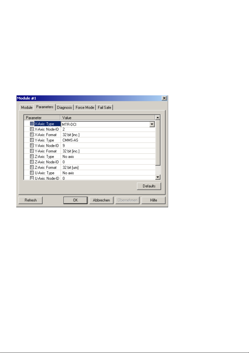
3.6.5 Configuration with CPX-FMT
The following figures show the configuration of the
CPX-CM-HPP with CPX-FMT.
Fig. 3/3: Configuration with FMT: Selection axis.
3-28
Festo CPX-CM-HPP-EN 2017-06b English
Page 65
3. Commissioning
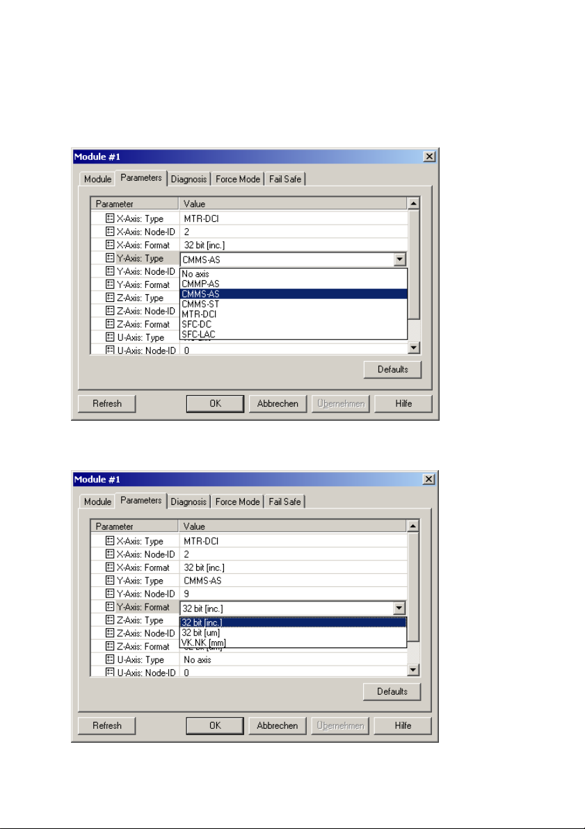
Fig. 3/4: Configuration with FMT: Selection axis type.
Fig. 3/5: Configuration with FMT: Selection format.
Festo CPX-CM-HPP-EN 2017-06b English
3-29
Page 66
3. Commissioning
3.7 Force
Through forcing, you can force input and output signals.
Actual input signals or status changes by program are
ignored and replaced by the force values.
Warning
High acceleration forces of the connected actuators.
Uncontrolled actuator movements can cause collisions
which can lead to serious injury.
Be very careful when forcing in order to avoid undesired
movements of the actuators.
Make sure that nobody enters the sphere of influence of
the drives or other connected actuators.
The following options are available for forcing:
– Handheld type CPX-MMI
3-30
– Front unit controller
– Higher-order controller
You can define with the CPX terminal if forcing will be
possible after the system start.
For additional information about forcing, refer to the
CPXsystem description (CPX-SYS-...).
Festo CPX-CM-HPP-EN 2017-06b English
Page 67

Diagnostics and error treatment
Chapter 4
Diagnostics and error treatment
4-1Festo CPX-CM-HPP-EN 2017-06b English
Page 68

4. Diagnostics and error treatment
Contents
4. Diagnostics and error treatment 4-1..................................
4.1 Summary of diagnostics options 4-3...................................
4.2 Errors and warnings 4-4.............................................
4.2.1 Behaviour in case of errors and warnings 4-4....................
4.2.2 Acknowledge errors 4-4.....................................
4.2.3 Error numbers 4-5..........................................
4.3 Diagnostics via display 4-11..........................................
4.4 Diagnostics via LEDs 4-13............................................
4.5 Diagnostics at the CPX terminal 4-15...................................
4.5.1 Status bits in the system status of the CPX terminal 4-15............
4.5.2 I/O diagnostic interface and diagnostic memory 4-16..............
4.5.3 Definition of diagnostics channels 4-19..........................
4-2
Festo CPX-CM-HPP-EN 2017-06b English
Page 69
4. Diagnostics and error treatment
4.1 Summary of diagnostics options
The CPX-CM-HPP supports various options for diagnostics
and error handling in the CPX terminal. An overview is
provided by Tab. 4/1.
Diagnostics
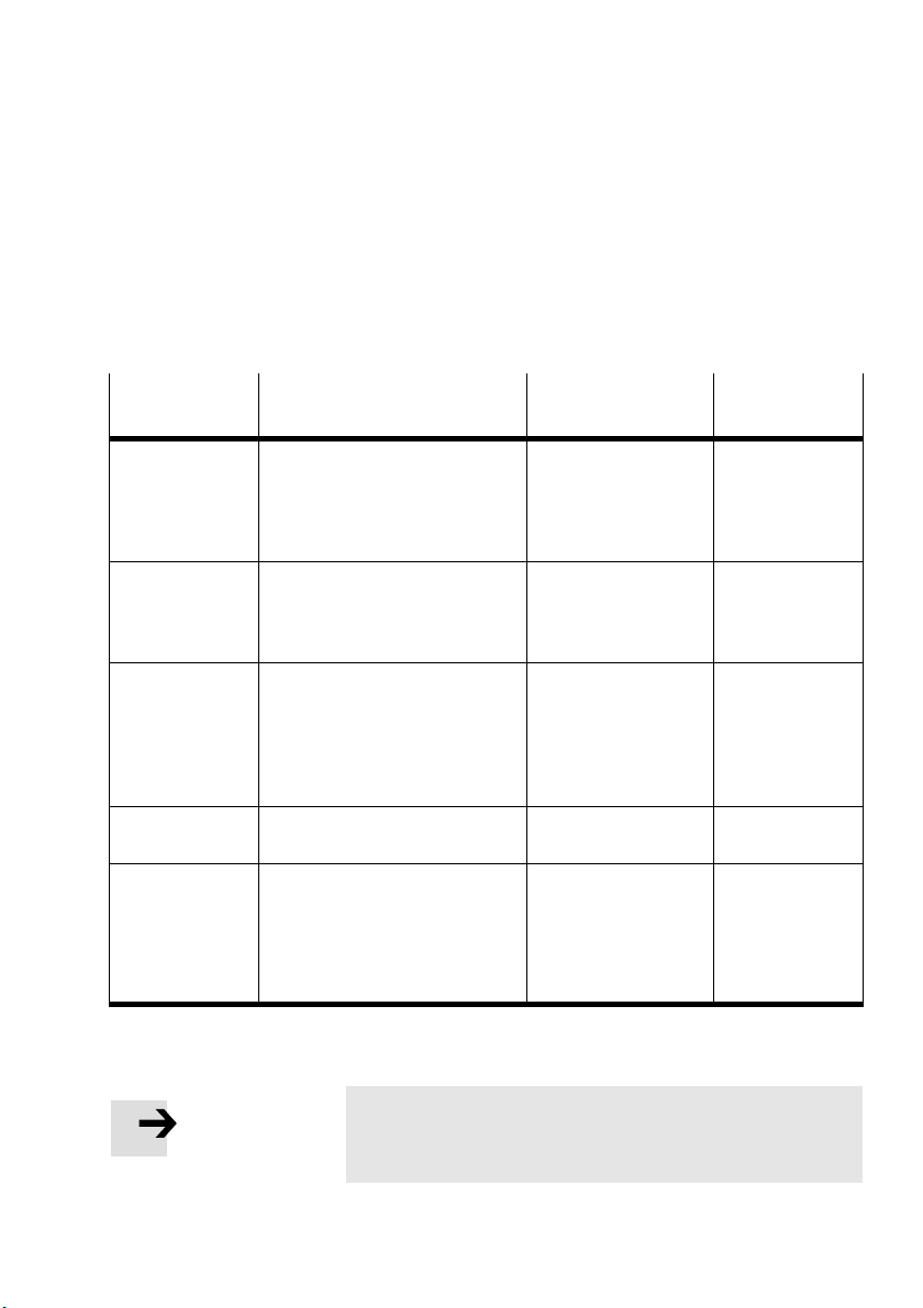
Brief description Advantages Detailed
option
Error messages The CPX-CM-HPP reports specific
Diagnostics with
the handheld
type code
CPX-MMI
Diagnostics with
the display on the
CPX-CM-HPP
LED display The LED Error indicates error
Status bits, I/O
diagnostics
interface and
specific
diagnostic
functions
malfunctions of the connected
drives as error messages (error
groups) to the CPX master.
Diagnostic information can be
shown on the CPX-MMI in a
user-friendly and menu-driven
manner.
The display on the CPX-CM-HPP
shows status information and the
error number of an actual
malfunction (error or warning) of
the individual axes in alternating
order.
states directly.
The errors recognised by the
CPX-CM-HPP are reported in some
cases to the CPX bus node or
CPX-FEC/CPX-CEC with special
additional information.
Error messages can be
evaluated via the CPX
bus node or
CPX-FEC/CPX-CEC or
CPX-MMI.
Rapid detection of
errors “on-site”.
Rapid detection of
errors “on-site”.
Rapid detection of
errors “on-site”.
Fast access to error
messages via the
fieldbus, etc.
description
See Chapter 4.2
and CPX system
description
See Chapter A.3
and description
for handheld
CPX-MMI.
See Chapter 4.3
See Chapter 4.4
See CPX system
description and
descriptions of
the respective
CPX modules.
Tab. 4/1: Diagnostics options
Note
The available diagnostic information depends on the
settings of the CPX bus node or the CPX-FEC/CPX-CEC.
Festo CPX-CM-HPP-EN 2017-06b English
4-3
Page 70

4. Diagnostics and error treatment
4.2 Errors and warnings
The CPX-CM-HPP supports detailed error handling and
evaluation. A list of errors is provided in Section 4.2.3.
4.2.1 Behaviour in case of errors and warnings
Depending on the parameterisation of the motor controller, a
malfunction is reported to the CPX-CM-HPP either as an error
message or as a warning.
Warning
When an error occurs, only the affected axis will stop.
Allother axes will continue their movement. Unintended
actuator movements can thereby lead to collisions and
result in serious injuries.
Make sure that no personnel enters the sphere of
influence of the drives or other connected actuators.
If applicable, program the higher-order PLC so that the
other axes will be blocked automatically in the event of
an error.
If a warning occurs, the respective drive can continue to run
depending on the selected setting. Some warnings will only
be displayed for a certain period of time.
4.2.2 Acknowledge errors
The following options are available to delete the error:
– Acknowledge the error with CCON.Reset.
– Acknowledge the error with the CPX-MMI.
– Switch the operating voltage off and then on again.
4-4
Festo CPX-CM-HPP-EN 2017-06b English
Page 71

4. Diagnostics and error treatment
4.2.3 Error numbers
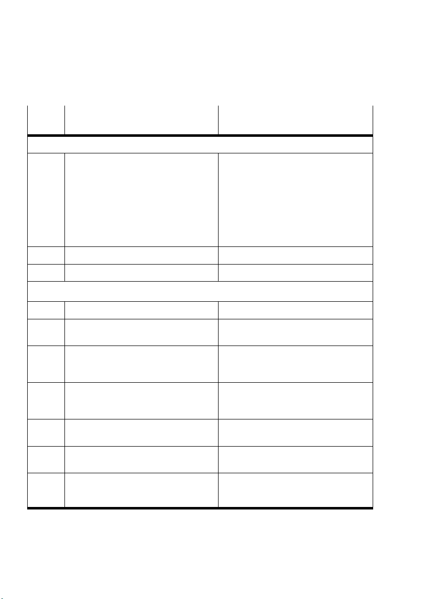
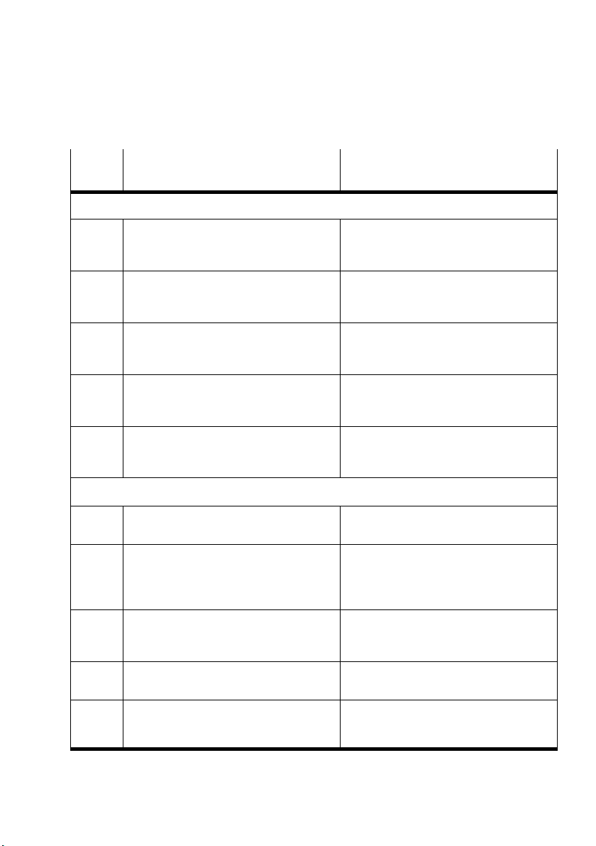
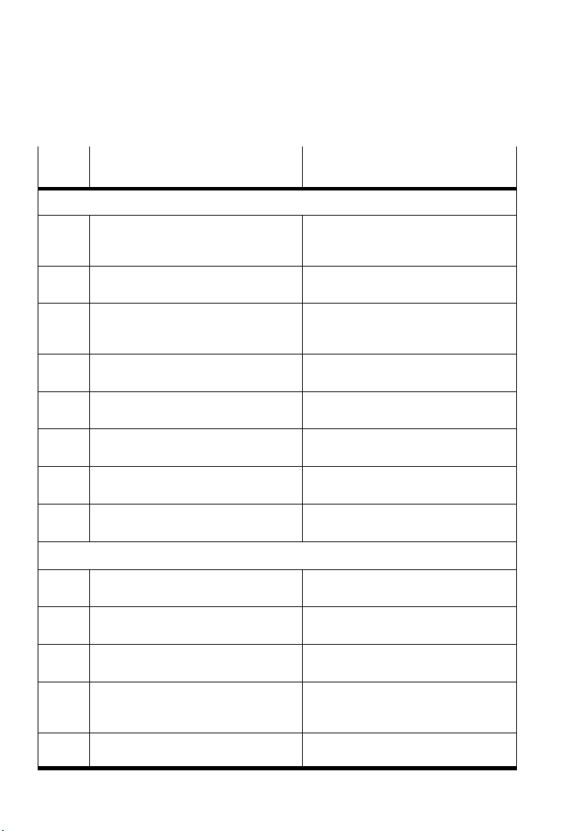
Error messages are consolidated in error groups in the
CPXterminal. For an overview of the error messages of the
CPX-CM-HPP, see Tab. 4/2.
On the handheld type code CPX-MMI, the error groups of the
individual drives are displayed in the Diagnostics menu.
When an axis is selected, the error message for this axis is
displayed in clear text.
Because it is partially possible to define if a status is a
warning or an error in the drives, it is not possible to indicate
the status type of the message in the CPX terminal with
certainty. Therefore, the error numbers in the table below
may not only be errors but also warnings.
The CPX-CM-HPP offers a 3-stage error diagnostics:
1. The CPX-CM-HPP reports the error group no. to the
CPXmaster (error group no. 100 – 109).
Festo CPX-CM-HPP-EN 2017-06b English
2. The precise error below the error group is displayed on
the 7-segment display of the CPX-CM-HPP and can be
read out with the CPX-MMI.
3. Additional diagnostics options are then available via the
displayed error messages directly at the motor controller.
For additional notes, refer to the descriptions of the
respective motor controllers.
The list of possible error causes in the table below does
notclaim to be complete. If in doubt, contact your local
FestoService.
4-5
Page 72
4. Diagnostics and error treatment
Error
Description and possible cause Error handling
No.
Configuration error (CPX error category 100)
1 CAN communication cannot be established
2 Wrong axis type in the configuration Correct axis type
3 FHPP data profile not active Correct communication profile
Execution error (CPX error category 101)
10 Axis is not referenced Carrying out homing
11 Error when homing is started
12 Error during homing
13 SW limit switch
– Logic voltage of the actuator not
switched on.
– Cable defective.
Switch on the logic voltage of the
actuator
– Wrong communication settings
(Profile:FHPP, Node ID, Baud rate).
– No terminating resistors.
Replace cable
Correct settings
Install terminating resistors
– Internal drive error. Contact Festo
– Enable signal not set. Check control signals for homing.
Checkcontroller parameters
– Internal software limit of end position
Check software end position settings
reached.
14 Neg. limit switch
– Neg. limit switch actuated. Check neg. limit switch
15 Pos. limit switch
– Pos. limit switch actuated. Check pos. limit switch
16 Positioning error
– Lag limit reached
– Controller parameters incorrect.
4-6
Check controller parameters
Correct controller parameters
Festo CPX-CM-HPP-EN 2017-06b English
Page 73
4. Diagnostics and error treatment
Error
No.
Position record error (CPX error category 102)
20 Unknown command
– Invalid entry in the record table of the
drive
21 Impermissible record number
– Selection of a record number that does
not exist in the record table of the drive
22 Acceleration not permitted
– Invalid values in the record table of the
drive
23 Invalid jump destination
– Jump to a record that does not exist in
the record table of the drive
24 No position data record
– Selection of a record without content in
the record table of the drive
Controller error (CPX error category 103)
30 Arithmetic error in FHPP factor group
– Internal error of the motor controller Contact Festo
31 Following error monitoring
– Following error due to excessive load
– Incorrect settings of the drive
parameters (speed, acceleration, delay)
Error handlingDescription and possible cause
Correct entry
Select another record
Correct values
Correct jump destination
Create a position data record or select
adifferent record
Check controller parameters
Correct settings
32 Invalid operating mode
– Incorrect setting of the operating mode
in the FHPP profile
33 Standstill monitoring
– Axis is not at standstill Check controller parameters
34 Fast Stop error
– Axis could not brake within the specified
period of time
Festo CPX-CM-HPP-EN 2017-06b English
Correct setting
Check controller parameters
4-7
Page 74
4. Diagnostics and error treatment
Error
Error handlingDescription and possible cause
No.
104 System error_A Software, Communication (CPX error category 104)
40 CAN bus communication error during
41 Stack overflow
42 Error during initialisation/HW error/FW error
43 Error in current measurement
44 Node guarding or heart beat
45 RS232 communication error
46 Internal conversion error
47 IRQ overflow
System error_B Hardware (CPX error category 105)
transmission
– Internal drive error Contact Festo
– Internal drive error
– Internal drive error
– Internal drive error Contact Festo
– Internal drive error Contact Festo
– Internal drive error Contact Festo
– Internal drive error Contact Festo
– Internal drive error Contact Festo
Contact Festo
Contact Festo
50 Overvoltage in intermediate circuit
– Internal drive error Contact Festo
51 Undervoltage in intermediate circuit
– Internal drive error Contact Festo
52 Failure of internal voltage
– Internal drive error Contact Festo
53 SD card error
– Internal drive error
54 Missing HW component in the controller
– Internal drive error Contact Festo
4-8
Contact Festo
Festo CPX-CM-HPP-EN 2017-06b English
Page 75
4. Diagnostics and error treatment
Error
No.
55 Checksum error
– Internal drive error Contact Festo
56 Flash error
– Internal drive error Contact Festo
Error in the controller (CPX error category 107)
70 Undervoltage at the controller (LogicVolt)
– No voltage at the motor controller Check the power supply
71 I2t error (overheating in the controller)
– Excessive load at the output of the
controller
72 Undervoltage or overload current at
digitalI/O
– Internal drive error Contact Festo
73 No calibration data
– Hardware error at the motor controller
– SD card defective Contact Festo
74 No user parameter record
– Hardware error at the motor controller
– SD card defective Contact Festo
75 Operating hour counter error
– Hardware error at the motor controller
– SD card defective Contact Festo
Error handlingDescription and possible cause
Reduce load. Check controller
parameters.
Error in the measuring system (CPX error category 108)
80 Angle encoder error
81 Old angle encoder parameter record
82 Index Pulse Warning Contact Festo
Festo CPX-CM-HPP-EN 2017-06b English
– Encoder or resolver defective
– Angle encoder cable defective
– Hardware error at the motor controller
– Internal drive error Contact Festo
Check the cable and replace if necessary
Contact Festo
4-9
Page 76
4. Diagnostics and error treatment
Error
Error handlingDescription and possible cause
No.
Error in the motor or output stage (CPX error category 109)
90 Motor stop
91 Error in driver supply
92 Power section over-temperature
93 Motor overtemperature
94 Short circuit at output stage
95 Motor temperature 5° below maximum
96 I2t error
99 General error cannot be assigned
– Internal drive error Contact Festo
– Input bridge of the power supply
defective
– Intermediate circuit defective Contact Festo
– Internal drive error Contact Festo
– Temperature sensor in motor defective
– Motor too hot Contact Festo
– Internal drive error Contact Festo
– Internal error in motor Contact Festo
– Internal error in motor Contact Festo
– Other errors Contact Festo
Tab. 4/2: CPX-CM-HPP error messages
4-10
Festo CPX-CM-HPP-EN 2017-06b English
Page 77

4. Diagnostics and error treatment
4.3 Diagnostics via display
The three-digit 7-segment display shows the status of the
individual axis consecutively. The error number or warning
number is displayed for malfunctions, see Section 4.2.3,
Page4-5.
1 1st position
(e.g. identifying letter
for parameters or
status type)
2 Point for separation
1
2
3 2nd and 3rd position
(e.g. value, stage or
status information)
Fig. 4/6: Display/7 segment display
The following table describes the meaning of the individual
positions of the 7-segment display.
1st position
Axis no.
1 Display of the state of the X-axis
2 Display of the state of the Y-axis
3 Display of the state of the Z-axis
4 Display of the state of the U-axis
2nd position
Mode/
Error no.
3rd position
Status/
Error no.
Significance
3
Festo CPX-CM-HPP-EN 2017-06b English
4-11
Page 78
4. Diagnostics and error treatment
1st position
Axis no.
2nd position
Mode/
Error no.
in
Initialization
S
Set selection
d
Direct mode
E
Error
12
u
Warning
28
Significance3rd position
Status/
Error no.
Display initialisation
Connection set-up and initialisation of the axes
consecutively. The initialisation for the next axis
will not start until the initialisation for the current
axis has been completed successfully.
0 Axis is switched on (Axis is READY)
1 Controller enable (Axis is ENABLED)
2 Axis is referenced (Axis is REFERENCED)
0 Axis is switched on (Axis is READY)
1 Controller enable (Axis is ENABLED)
2 Axis is referenced (Axis is REFERENCED)
Error No.: 12
First, the display shows “E” and then “12”.
Warning: 28
First, the display shows “u” and then “28”.
Tab. 4/3: Information on the three-digit 7-segment display
4-12
Festo CPX-CM-HPP-EN 2017-06b English
Page 79
4. Diagnostics and error treatment
4.4 Diagnostics via LEDs
The following LEDs are available on the CPX-CM-HPP for
diagnosing the CPX terminal.
PL (Power Load) – Load supply
LED (yellow) Sequence Status Error handling
LED not illuminated
LED illuminated
Tab. 4/4: PL LED
ON
OFF
ON
OFF
Power supply failure Ensure the power supply.
Power supply OK –
Festo CPX-CM-HPP-EN 2017-06b English
4-13
Page 80
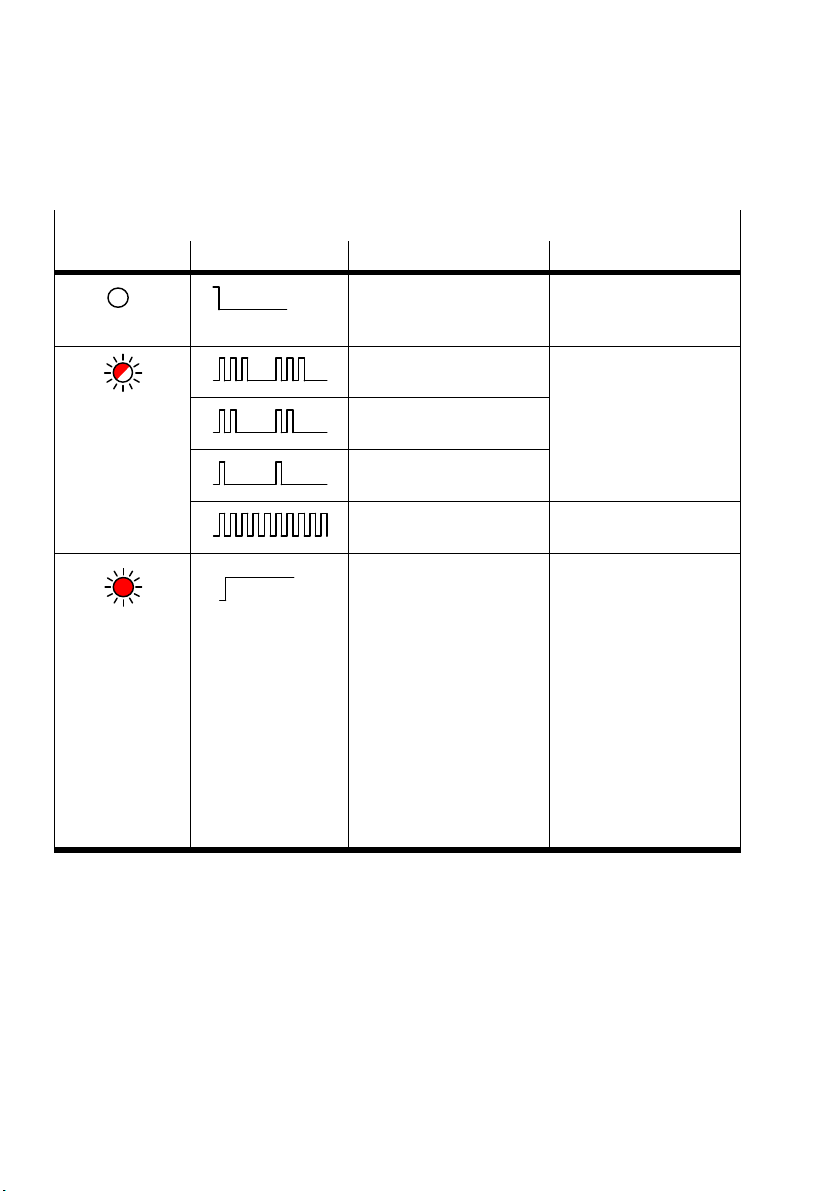
4. Diagnostics and error treatment
ERROR – Error
LED (red) Sequence Status Error handling
LED not illuminated
LED flashing
LED illuminated
ON
OFF
ON
OFF
ON
OFF
ON
OFF
ON
OFF
ON
OFF
No error. –
CPX system error, CPX error
category 3
CPX-CMXX error, CPX error
category 2
CPX system error, CPX error
category 1
Software update (flash
programming) active
1. CPX-CM-HPP is initialised
2. Communication or drive
error. The states of the axis
See CPX system
description
–
–
are shown in succession.
Example 1: Only one axis is
configured and reports an
error. Result: The error LED
is illuminated continuously
Example 2: 4 axes are
configured, but only one
reports and error. Result:
The error LED is always
illuminated when the status
of the faulty axis is
displayed on the display.
Tab. 4/5: ERROR LED
4-14
Festo CPX-CM-HPP-EN 2017-06b English
Page 81

4. Diagnostics and error treatment
4.5 Diagnostics at the CPX terminal
Malfunctions of the connected axes are reported as CPX error
group to the CPX master (CPX bus node or
CPX-FEC/CPX-CEC). One diagnostic channel is thereby
available for each drive Tab. 4/9. The following sections
include the special features of the representation for the
CPX-specific diagnostics options.
– Status bits (see Section 4.5.1)
– Diagnostic memory with CPX error groups
(I/Odiagnostics interface, see Section 4.5.2)
4.5.1 Status bits in the system status of the CPX terminal
A CPX-CM-HPP error is always specified in the system status
of the CPX terminal as follows:
Festo CPX-CM-HPP-EN 2017-06b English
Module type in which an error has occurred:
– Bit 0 - 2 = 0
– Bit 3 = 1:
Error in analogue/function or technology module
Error type
– Bit 4 - 6 = 0
– Bit 7 = 1: Other error
Further notes on the structure of the status bits can be found
in the CPX system description (CPX-SYS-...).
4-15
Page 82

4. Diagnostics and error treatment
4.5.2 I/O diagnostic interface and diagnostic memory
The CPX-CM-HPP reports the CPX error group to the
CPXmaster (CPX bus node or CPX-FEC/CPX-CEC).
Diagnostics via the CPX error group can be carried out via the
I/O diagnostics interface and the diagnostics memory of the
CPX terminal.
Diagnostics memory data (I/O diagnostics interface)
The representation of diagnostic messages of the
CPX-CM-HPP in the diagnostics memory of the CPX terminal
occurs as shown in Tab. 4/6.
4-16
Festo CPX-CM-HPP-EN 2017-06b English
Page 83
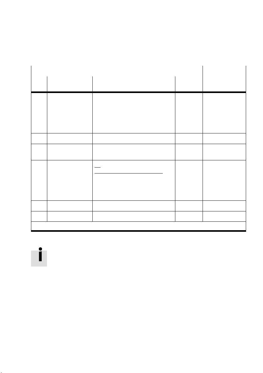
4. Diagnostics and error treatment
Diagnostic memory data (10 bytes per entry, max. 40 entries) Function No
Byte
Designation
no.
1 ... 5 Days [day]
Hours [h]
Minutes [m]
Seconds [s]
Milliseconds [ms]
6 Module code Module code of the CPX-CM-HPP: 175 0 ... 255 n = 10 * d + 5
7 Module position
[Pos]
8 Channel number Bit
9 Error number [FN] CPX error group (see Section 4.2.3) 100 ... 109 n = 10 * d + 8
10 Following channels For CPX-CM-HPP always 0 0 ... 63 n = 10 * d + 9
1)
d (diagnostic event) [NB] = 0 ... 39 ; most current diagnostic event = 0
Description Value 3488 + n
Time specification of the reported
error, measured from the point when
the power supply is switched on
(CPXstandard).
Module number of the CPX module
that signaled the error.
10 Channel Description
00 I1 X-axis
01 I2 Y-axis
10 I3 Z-axis
11 I4 U-axis
0 ... 255
0 ... 23
0 ... 59
0 ... 59
0 ... 99
(128...227)
0 ... 47 n = 10 * d + 6
0 ... 255 n = 10 * d + 7
n = 10 * d + 0
Tab. 4/6: Diagnostic memory data of the CPX-CM-HPP
Notes on diagnostics with the I/O diagnostics interface are
found in the CPX system description.
1)
Festo CPX-CM-HPP-EN 2017-06b English
4-17
Page 84
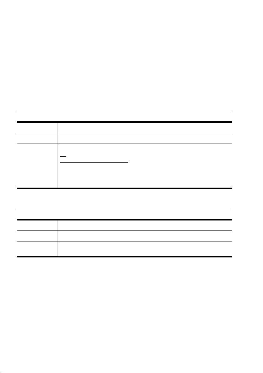
4. Diagnostics and error treatment
Diagnostic data of the module (I/O diagnostic
interface)
The specific representation of module diagnostic data (error
messages) of the CPX-CM-HPP occurs as shown in Tab. 4/7
and Tab. 4/8.
Module diagnostic data: Location of the error
Function no. 2008 + m * 4 + 0; m = module number (0 ... 47)
Description Describes where the relevant error occurred.
Bit Bit 0 ... 7 Location where the error arose
Tab. 4/7: Location where the error arose
Bit
10 Channel Description
00 I1 X-axis
01 I2 Y-axis
10 I3 Z-axis
11 I4 U-axis
Module diagnostic data: Module error number
Function no. 2008 + m * 4 + 1; m = module number (0 ... 47)
Description CPX error category (see Chapter 4.2.3)
Bit Bit 0 ... 7
Value range: 100..109
Tab. 4/8: Module error number
4-18
Festo CPX-CM-HPP-EN 2017-06b English
Page 85
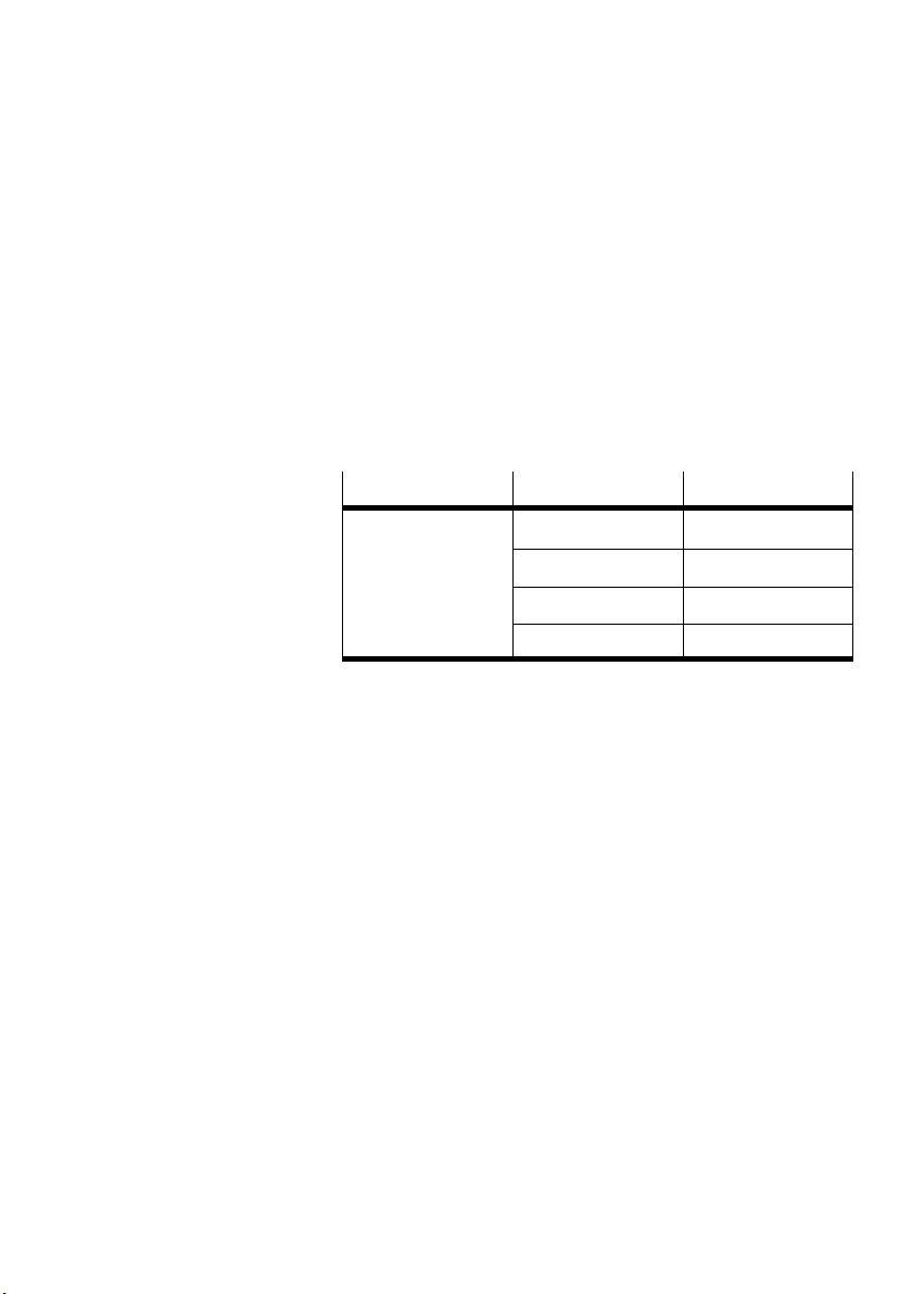
4. Diagnostics and error treatment
4.5.3 Definition of diagnostics channels
Four input channels are defined as diagnostics channels
forthe implementation of the axis-specific diagnostics. The
individual diagnostics channels report errors for the
respective drive.
The table below shows the definition of the diagnostics
channels
Input channel 1 1
Channel number Axis
2 2
3 3
4 4
Festo CPX-CM-HPP-EN 2017-06b English
Tab. 4/9: Definition of diagnostics channels
4-19
Page 86

4. Diagnostics and error treatment
4-20
Festo CPX-CM-HPP-EN 2017-06b English
Page 87

Technical appendix
Appendix A
Technical appendix
A-1Festo CPX-CM-HPP-EN 2017-06b English
Page 88

A. Technical appendix
Contents
A. Technical appendix A-1.............................................
A.1 Technical data A-3..................................................
A.2 Accessories A-4....................................................
A.3 Device-specific information on the CPX-MMI handheld A-5.................
A-2
Festo CPX-CM-HPP-EN 2017-06b English
Page 89
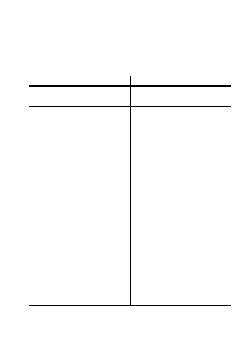
A. Technical appendix
A.1 Technical data
Type CPX-CM-HPP
General technical data of the CPX terminal See CPX system description (CPX-SYS-...)
Total number of axes Max 4 axes per CPX-CM-HPP
Device-specific diagnostics – Channel and module-oriented diagnostics
Configuration support CPX-MMI
LED display PL: Power supply
Axis connection
– Protocol
– Baud rate
– Fieldbus interface
– Max. cable length
CPX module code 175
Max. address capacity
– Inputs
– Outputs
Degree of protection
in accordance with IEC 60529, plug connector
inserted
Nominal operating voltage 24 VDC
Operating voltage range 18 ... 30 VDC
Intrinsic current consumption
– at nominal operating voltage Typ. 80 mA
Power failure buffering 10 ms
– Undervoltage/short circuit of modules
– Diagnostic memory
Error Error
CAN bus
FHPP
1 Mbit/s
Socket M9, 5-pin
30 m
32 bytes
32 bytes
IP65
Product weight (without interlinking block) Approx. 140 g
Dimensions W x L x H 50 mm x 107 mm x 55 mm
Festo CPX-CM-HPP-EN 2017-06b English
A-3
Page 90

A. Technical appendix
A.2 Accessories
Accessories for the CPX-CM-HPP can be found in our
catalogue under www.festo.com/catalogue.
A-4
Festo CPX-CM-HPP-EN 2017-06b English
Page 91
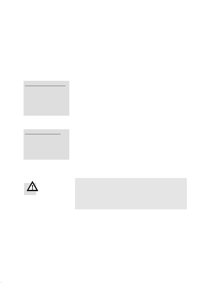
A. Technical appendix
_
A.3 Device-specific information on the CPX-MMI handheld
Some information of the CPX-CM-HPP is specially depicted at
the CPX MMI. This information is explained in the following by
means of some examples.
System Overview _
CPX terminal
0: FEC Controller
1: CM-HPP FHPP-Gateway
2: 8DI/8DO Multi I/O
_____________________________________________________
Diag OK
1: CM-HPP _
Monitoring/Forcing (M)
Diagnostics (D)
Parameters (P)
Module Data (MD)
___________________________________ ___________________
Back OK
The CPX-CM-HPP is displayed as module “CM-HPP
FHPP-Gateway” on the MMI. The complete name is displayed
with the button “<-->”.
The module related menu options and functions are explained
below. Information about the system diagnosis that can be
called under [Diag] is provided further down.
The CPX-CM-HPP supports the following functions:
– Monitoring/Forcing (M)
– Diagnostics (D)
– Parameters (P)
– Module Data (MD)
Warning
Incorrect entries in the Force Mode, menu
[Monitoring/Forcing (M)], can cause unintended
movements and major property damage and
personalinjury!
Festo CPX-CM-HPP-EN 2017-06b English
A-5
Page 92
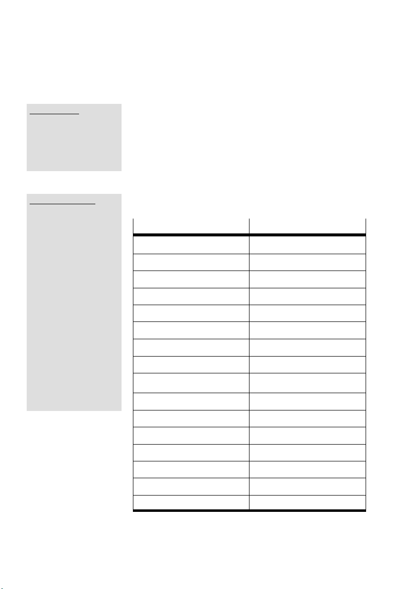
A. Technical appendix
1: CM-HPP
X-Axis: MTR-DCI
Y-Axis: CMMS-AS
Z-Axis: No Axis
U-Axis: No Axis
_____________________________________________________
Back OK
1: CM-HPP :M.X
Process state
_____________________________________________________
I: Enabled
I: Open
I: Warn
I: Fault
I: 24VL
I: Lock
I: OPM1
I: OPM2
I: /Halt
I: MC
I: Ref
O: Enable
O: /Stop
O: /Brake
O: Reset
O: Lock
O: OPM1
O: OPM 2
O: /Halt
_____________________________________________________
Back Force Mode
The current values of some of the inputs and outputs of the
connected motor controllers are displayed in the
[Monitoring/Forcing (M)] menu. The states of the inputs and
outputs can be forced with the “Force Mode” function.
The following I/O data is displayed for each axis:
Entry in CPX MMI
I: Enabled SCON.B0
I: Open SCON.B1
I: Warn SCON.B2
I: Fault SCON.B3
I: 24VL SCON.B4
I: Lock SCON.B5
I: OPM1 SCON.B6
I: OPM2 SCON.B7
O: Enable CCON.B0
O: /Stop CCON.B1
O: /Brake CCON.B2
FHPP-Bit
A-6
O: Reset CCON.B3
O: Lock CCON.B5
O: OPM1 CCON.B6
O: OPM2 CCON.B7
O: /Halt CPOS.B0
Festo CPX-CM-HPP-EN 2017-06b English
Page 93

A. Technical appendix
Note
The status changes are not updated continuously. The
allocation of the individual bits corresponds to the FHPP
profile. Please observe the drive-specific allocation
(e.g.see description CMM-FHPP-SW-DE)
Use the [Force Mode] function to switch to the [Force Mode]
menu. The following warning will be displayed for the first
call:
“Warning: If you modify settings, dangerous movements of
the actuators are possible.”
How to activate the write authorization for the CPX-MMI
handheld: Menu [Modify] function “Handheld write access”
enable/disable.
Select “Enable”
1: CM-HPP :M.Y
Drive Control (C)
Exex Record (E)
Jog / Ref / Teach (J)
_____________________________________________________
Back Mode OK
Festo CPX-CM-HPP-EN 2017-06b English
The following warning will be displayed:
“Warning: Your choice will disable host write access. Are you
sure?”
Confirm with “OK” to switch to the [Force Mode] menu.
The following functions are available in the [Force Mode]
menu:
– Drive Control (C)
– Exec Record (E)
– Jog / Ref / Teach (J)
– Mode
The following functions are available in the [Mode] menu:
– Clear force settings actual module/all modules
– Force Mode (Sys.par.) enable / disable
A-7
Page 94
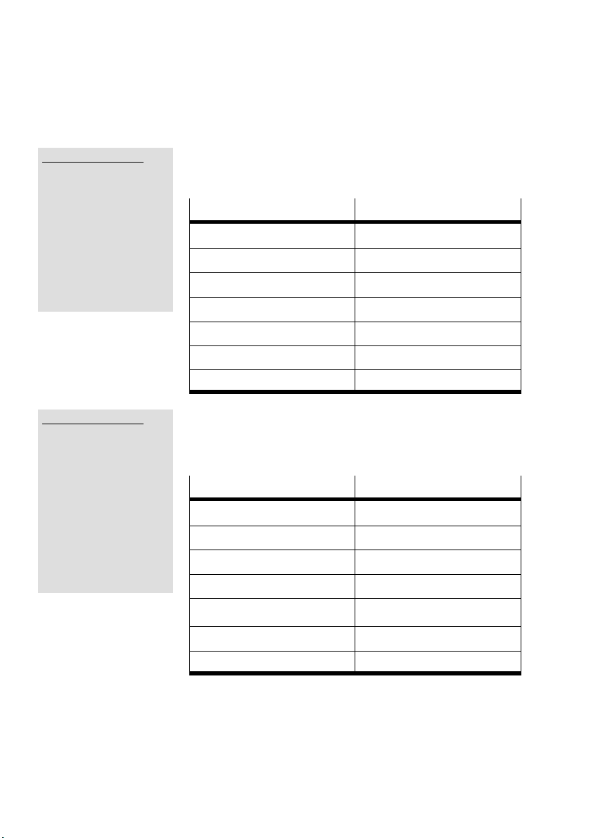
A. Technical appendix
1: CM-HPP :M.Y.C
Sys: Force Mode enabled
State
_____________________________________________________
Enable
/Stop
Reset
/Halt
Lock
OPM1
OPM2
_____________________________________________________
Back Set
1: CM-HPP :M.Y.E
Sys: Force Mode enabled
_____________________________________________________
Record No. 0
Set
Start
/Stop
/Halt
Clear
State
MC
Warn
Fault
_____________________________________________________
Back Set
The following commands can be set in the [Drive Control (C)]
menu:
Entry in CPX MMI
Enable CCON.B0
/Stop CCON.B1
Reset CCON.B3
/Halt CPOS.B0
Lock CCON.B5
OPM1 CCON.B6
OPM2 CCON.B7
FHPP-Bit
A drive record can be selected and started in the [Exec Record
(E)] menu. In addition, the following commands and status
information are available:
Entry in CPX MMI
Start CPOS.B1
/Stop CCON.B1
/Halt CPOS.B0
Clear CPOS.B6
FHPP-Bit
A-8
MC SPOS.B2
Warn SCON.B2
Fault SCON.B3
Festo CPX-CM-HPP-EN 2017-06b English
Page 95
A. Technical appendix
1: CM-HPP :M.Y.J
Sys: Force Mode enabled
Set
_____________________________________________________
() Home
() Jog neg
() Jog pos
() /Teach
State
MC ()
Ref ()
Warn ()
Fault ()
Teach Ack ()
_____________________________________________________
Back Set
1: CM-HPP :D _____
Diagnostics
X-Axis: 104-System error A
Y-Axis: No error
Z-Axis: No error
U-Axis: No error
_____________________________________________________
Back Detail
You can now carry out the following functions in the [Jog/
Ref/Teach (J) menu. In addition, the following some status
information is available:
Entry in CPX MMI
Home CPOS.B2
Jog neg CPOS.B4
Jog pos CPOS.B3
/Teach CPOS.B5
MC SPOS.B2
Ref SPOS.B7
Warn SCON.B2
Fault SCON.B3
Teach Ack SPOS.B3
FHPP-Bit
The CPX error groups of the axes are displayed in the
[Diagnostics (D)] menu.
1: CM-HPP :D.X ___
Fault X-Axis: 104-44
44- Node Guarding
or Heart Beat
_____________________________________________________
Back Res fault
Festo CPX-CM-HPP-EN 2017-06b English
The CPX error group, error number and the error text for the
selected axis is displayed in the [Detail] menu.
For the description, refer to Section 4.2.3.
A-9
Page 96

A. Technical appendix
1: CM-HPP : MD _ _
FHPP Gateway
Type Code: 175
Revision: 1
Serial No.: 0x00000010
_____________________________________________________
Back
Diag overview _
System Diagnostics
Trace data
1: CM-HPP FHPP-Gateway
_____________________________________________________
Back ok
System diagnostics _
Source of error
O Valve
O Output
O Input
Analogue / function mo
Type of error
O Undervoltage
O Short circuit / overload
O Wire fracture
Other error
_____________________________________________________
Back First error
The following information for the CPX-CM-HPP is displayed in
the [Module Data (MD)] menu (example).
– Module designation: FHPP Gateway
– Module type: 175
– Revision: 1
– Serial number: 0x00000010
System diagnostics functions are available in the [Diag] menu.
The CPX status bits are displayed in the [System diagnostics]
menu.
System Diagnostics
First faulty module
1: CM-HPP FHPP-Gateway
Fault number: 104
System error A
_____________________________________________________
Back
A-10
The following additional information about the current error is
displayed in the [First Error] menu.
– Module position and designation
– Number of the CPX error group
– Designation of the CPX error group
Festo CPX-CM-HPP-EN 2017-06b English
Page 97
A. Technical appendix
Trace data _
NB-FN-Pos-Day-h-m-s-ms
√ 0 107 1 000:0:2:57:13
_____________________________________________________
Back Detail
Trace data number 0
In fault Ch 1
System error A
Module position 1
CM-HPP: FHPP-Gateway
Days: 0
Hours: 0
Minutes: 2
Seconds: 57
Milliseconds: 13
_____________________________________________________
Back
The error memory is displayed in the [Trace Data] menu.
– Number of the entry (NB)
– Number of the CPX error group (FN)
– Module position (Pos)
– Timestamp in format Days:Hours:Minutes:
Seconds:Milliseconds (Day-h-m-s-ms) since the CPX
terminal was switched on
The following additional information about the current error is
displayed in the [Detail] menu.
– Channel number
– Designation of the CPX error group
– Module position
– Module designation
– Timestamp in format
Days:Hours:Minutes:Seconds:Milliseconds since
activation
Festo CPX-CM-HPP-EN 2017-06b English
Note
For additional information about the CPX-MMI handheld,
refer to the documentation CPX-MMI-1-...
A-11
Page 98

A. Technical appendix
A-12
Festo CPX-CM-HPP-EN 2017-06b English
Page 99

Index
Appendix B
Index
B-1Festo CPX-CM-HPP-EN 2017-06b English
Page 100

B. Index
Contents
B. Index B-1.........................................................
B-2
Festo CPX-CM-HPP-EN 2017-06b English
 Loading...