

Page 1
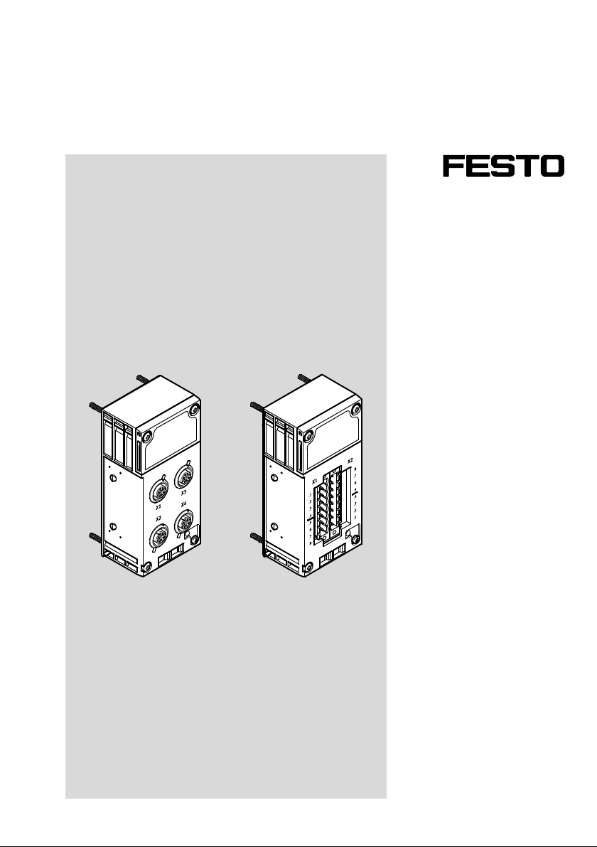
Terminal CPX
CPX-4AE-4AA-H
en Description
8083250
2017-12
[8083252]
Page 2

CPX-4AE-4AA-H
Translation of the original instructions
E/A-Modul CPX-4AE-4AA-H-EN
HART®, Torx® are registered trademarks of the respective trademark owners in certain countries.
Other symbols:
Note
Material damage or loss of function
Recommendations, tips, references to other documentation
Text designations:
Activities that may be carried out in any order
1. Activities that should be carried out in the order stated
– General lists
è Result of an action/References to more detailed information
2 Festo – CPX-4AE-4AA-H – 2017-12
Page 3

CPX-4AE-4AA-H
Table of contents
1 About this document 5......................................................
1.1 Further applicable documents 5...............................................
1.2 Product labelling 6..........................................................
1.3 Specified standards 6.......................................................
2 Safety 7..................................................................
2.1 General safety information 7..................................................
2.2 Intended use 7.............................................................
2.3 Training of specialised personnel 8.............................................
3 Additional information 8.....................................................
4 Service 8.................................................................
5 Product overview 8.........................................................
5.1 Function 8.................................................................
5.2 Structure of analogue module 9...............................................
5.3 Connection block 10..........................................................
5.3.1 Types 10...........................................................
5.3.2 Connection and display components 11..................................
5.4 Product-specific terms and abbreviations 12......................................
6 Mounting 13...............................................................
6.1 General instructions 13.......................................................
6.2 Mechanically coding the connection block 13......................................
6.3 Mounting the electronics module and connection block 16...........................
6.4 Dismounting the electronics module and connection block 17........................
7 Installation 18..............................................................
7.1 Prerequisites for installation 18................................................
7.2 Power supply 18.............................................................
7.3 Changing the configuration of the analogue current channels (DILswitches) 18..........
7.4 Electrical system 21..........................................................
7.4.1 Notices regarding the cable connection 21...............................
7.4.2 Attaching connecting cables to the connection block M12 21.................
7.4.3 Attaching connecting cables to the terminal connection block 22..............
7.4.4 Mechanically coding the terminal connection 25...........................
Festo – CPX-4AE-4AA-H – 2017-12 English 3
Page 4

CPX-4AE-4AA-H
7.5 Connection scenarios 26......................................................
7.5.1 2-wire connection of passive HART transmitters 26.........................
7.5.2 3-wire connection of passive HART transmitters 26.........................
7.5.3 4-wire connection of active HART transmitters 27..........................
7.5.4 2-wire connection of passive HART actuators 27...........................
7.5.5 4-wire connection of active HART actuators 28............................
8 Commissioning 29...........................................................
8.1 Requirements for commissioning 29.............................................
8.2 Process image and address space allocation 29....................................
8.3 HART variables 30...........................................................
8.4 Parameterisation 31.........................................................
8.4.1 Recommended parameterisation sequence 31............................
8.4.2 Overview of parameters 32............................................
8.4.3 Description of the module and channel parameters 33......................
8.5 Data format and range of values of the actual values 46.............................
8.5.1 Data format 46.....................................................
8.5.2 Input 4 … 20 mA - fixed data format 47...................................
8.5.3 Input 4 … 20 mA – scalable data format 47................................
8.5.4 Input 0 … 20 mA – fixed data format 48..................................
8.5.5 Input 0 … 20 mA – scalable data format 48................................
8.5.6 Output 4 … 20 mA – fixed data format 49.................................
8.5.7 Output 4 … 20 mA – scalable data format 49..............................
8.5.8 Output 0 … 20 mA – fixed data format 50.................................
8.5.9 Output 0 … 20 mA – scalable data format 50..............................
8.6 Scaling the range of values 51..................................................
9 Diagnostics 52..............................................................
9.1 General remarks 52..........................................................
9.2 Error messages 53...........................................................
9.3 LED indicator 55.............................................................
10 Technical data 57............................................................
Index 59........................................................................
4 Festo – CPX-4AE-4AA-H – 2017-12 English
Page 5
CPX-4AE-4AA-H
1 About this document
This document describes the mode of operation, mounting, installation and commissioning of the
product. Certain aspects of use are described in other documents and must be observed
è 1.1 Further applicable documents.
1.1 Further applicable documents
For all available product documentation è www.festo.com/pk
Document Table of contents
Brief description Instructions and important information on use
and safe application
Description of system CPX (CPX-SYS) Mode of operation, mounting, installation and
commissioning of CPX terminals
Description of bus node Commissioning, parameterisation and
diagnostics of terminal CPX with the bus node
Documentation for the components and the
connected peripherals
Documentation for the higher-order controller
and the additional participants in the network
Operating conditions for explosion protection For product versions with corresponding
Tab. 1 Further applicable documents
Usage of components
Commissioning and parameterisation of the
components
approval: operating conditions in potentially
explosive atmospheres
Festo – CPX-4AE-4AA-H – 2017-12 English 5
Page 6
CPX-4AE-4AA-H
1.2 Product labelling
6
5
4
1
2
3
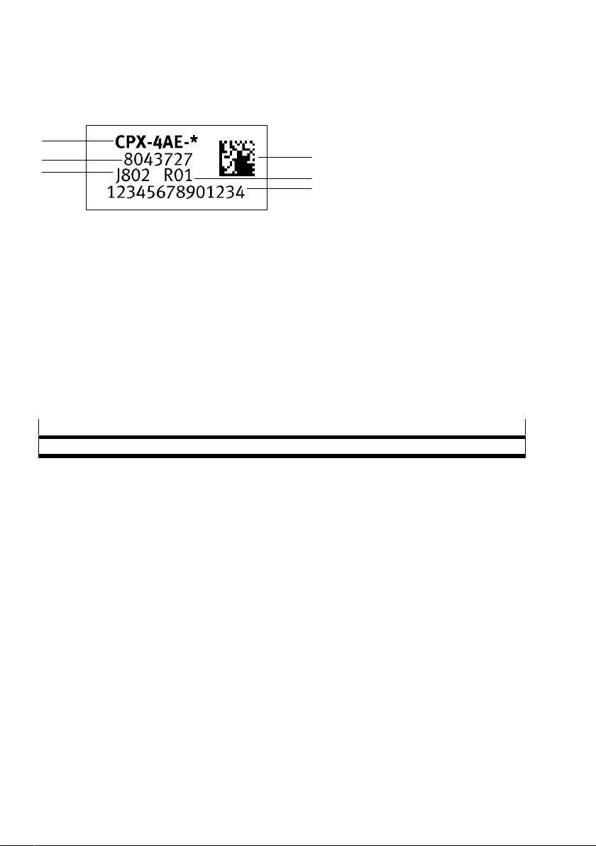
1 Data Matrix Code
2 Revision code
3 14-character serial number
Fig. 1 Product label – example
The product label is located on the top of the fibre-optic cable è Fig. 3.
Scanning the printed Data Matrix Code with an appropriate device calls the Festo Support Portal, with
information appropriate for the product. Alternatively, the Product Key (11-digit alphanumeric code on
the product label) can be entered in the search field of the Support Portal.
4 Production time period (encoded)
5 Part number
6 Product description
1.3 Specified standards
Version status
NAMUR NE43:2003-02
Tab. 2 Specified standards
6 Festo – CPX-4AE-4AA-H – 2017-12 English
Page 7
CPX-4AE-4AA-H
2 Safety
2.1 General safety information
Only use the product if it is in perfect technical condition.
Observe product labelling.
Take into consideration the ambient conditions at the location of use.
Prior to mounting, installation and maintenance work: switch off the power supply.
Observe the handling specifications for electrostatically sensitive devices.
Seal unused connections with cover caps to achieve the required degree of protection.
Use connection hardware with the required degree of protection.
Store the product in a cool, dry, UV-protected and corrosion-protected environment.
Ensure that storage times are kept to a minimum.
2.2 Intended use
The analogue module is determined only for use in terminal CPX and terminal CPX-P of Festo.
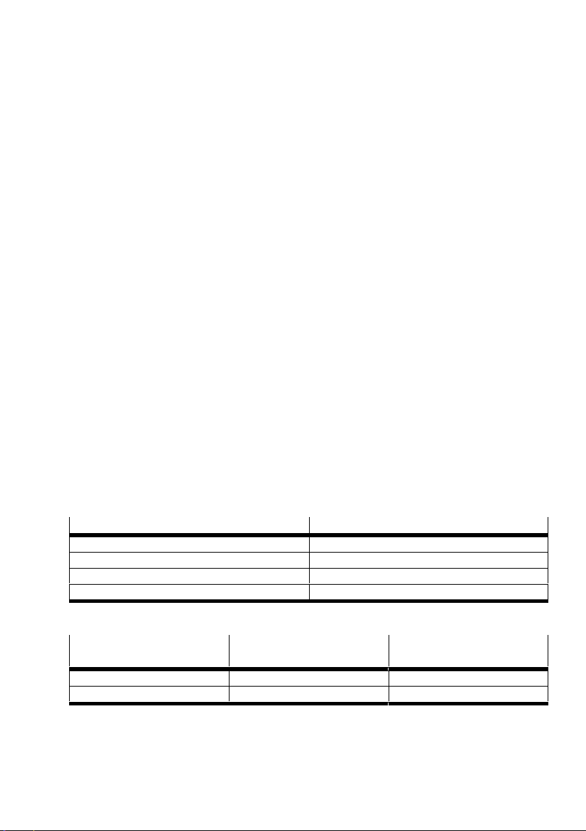
Operate the product only at suitable bus nodes CPX è Tab. 3.
Connect a maximum of 5 analogue modules with HART functionality to the bus nodes CPX-FB13
(PROFIBUS).
Use only permissible combinations of module components è Tab. 4.
The product may only be used in its original status without unauthorized modifications.
Only the conversions or modifications described in this and further applicable documents
arepermitted.
Use the product only in an industrial environment. Outside of industrial environments, e.g. in
commercial and mixed-residential areas, actions to suppress interference may have to be taken.
Bus node Required revision
CPX-FB13 (PROFIBUS) from Rev 34
CPX-FB33 (PROFINET IO) from Rev 33
CPX-M-FB34 (PROFINET IO) from Rev 33
CPX-M-FB35 (PROFINET IO) from Rev 33
Tab. 3 Suitable bus nodes and required revisions
Interlinking block Connection block
CPX-P-AB-4XM12-4POL
Metal version Permissible Permissible
Plastic version Not permissible Permissible
Tab. 4 Permissible combination of connection block and interlinking block
Festo – CPX-4AE-4AA-H – 2017-12 English 7
Connection block
CPX-P-AB-2XKL-8POL
Page 8

CPX-4AE-4AA-H
2.3 Training of specialised personnel
This document is intended for qualified personnel. Experience with electrical control systems is
required in order to understand this documentation.
3 Additional information
– Accessories è www.festo.com/catalogue
– Spare parts è www.festo.com/spareparts
– Documents and literature è www.festo.com/sp
4 Service
Contact your regional Festo contact person if you have technical questions è www.festo.com
5 Product overview
5.1 Function
The analogue module with HART functionality provides analogue current inputs and current outputs
and enables the recording and further processing of analogue current signals.
– 4 analogue current channels, configurable as input or output by DIL switch
– LED indicators for status and fault indications on the module
– Error control parameterisable
– Scalable range of values (16 bits)
– Channel-wise signal range configurable:
– Without HART: 0 … 20 mA or 4 … 20 mA
– With HART: 4 … 20 mA
– Connection of the following field devices possible:
– 2-, 3- or 4-wire sensors
– 2-, 3- or 4-wire actuators
– HART functionality according to HART Communication Protocol Specification 7.5
– Support of the HART protocol in versions 5, 6 and 7
8 Festo – CPX-4AE-4AA-H – 2017-12 English
Page 9
CPX-4AE-4AA-H
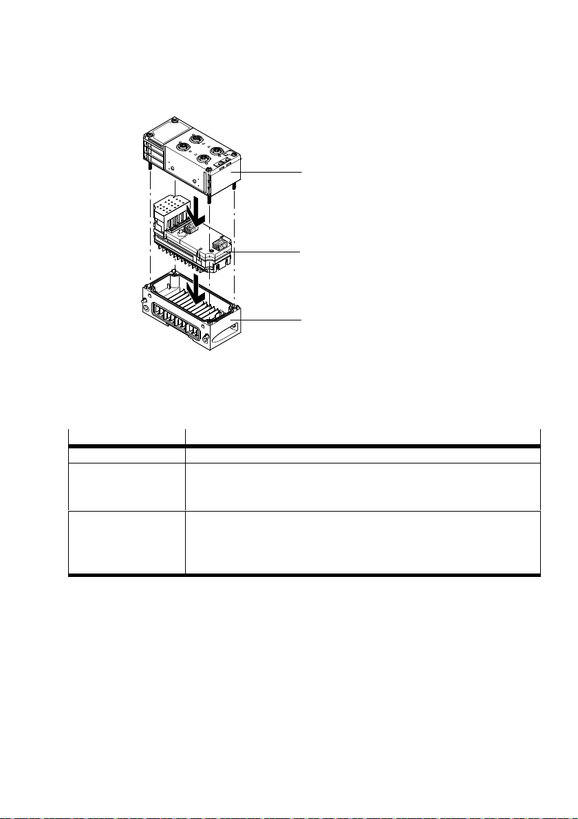
5.2 Structure of analogue module
1
2
3
1 Connection block
2 Electronics module
Fig. 2 Structure of the analogue module — example
Module component Description
Connection block – Provides the connections for field devices è Chap. 5.3.
Electronics module – Contains the electronic components of the module
– Connects to the connection block and interlinking block through the
plug connector
Interlinking block – Housing bottom part for electrical and mechanical linking of the
CPXmodules
– Variant with connection possible for operating and load voltage
– Mounting option for entire terminal CPX
Tab. 5 Module components of analogue module
3 Interlinking block with contact rails
Festo – CPX-4AE-4AA-H – 2017-12 English 9
Page 10
CPX-4AE-4AA-H
5.3 Connection block
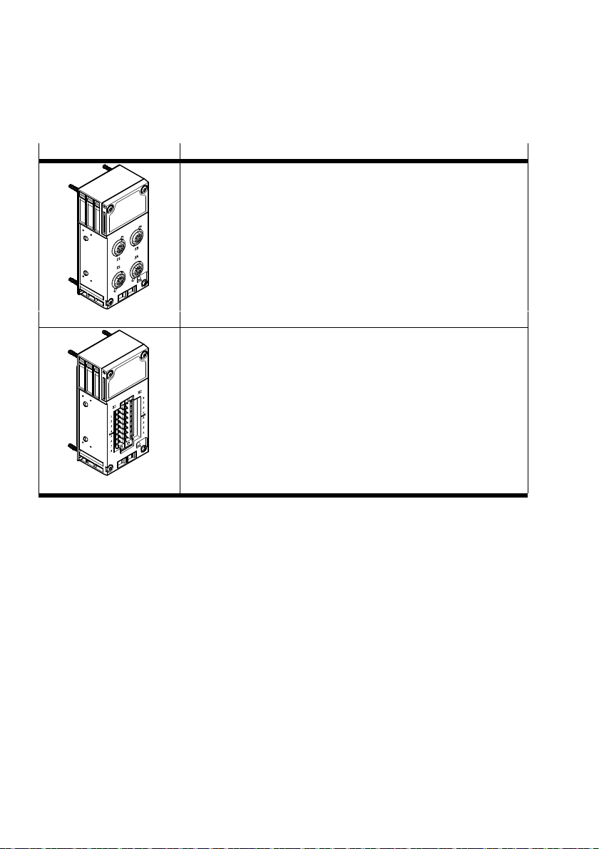
5.3.1 Types
Connection block type Description
M12 connection block
– 4 M12 sockets, 4-pin
– For round plug connector M12x1 and SPEEDCON M12
– Screening possible using metal thread
CPX-P-AB-4XM12-4POL
Terminal connection block
– 2 pin strips COMBICON, 8-pin
– For terminal strips in spring-loaded and screw terminal technology
CPX-P-AB-2XKL-8POL
Tab. 6 Connection blocks
10 Festo – CPX-4AE-4AA-H – 2017-12 English
Page 11
CPX-4AE-4AA-H
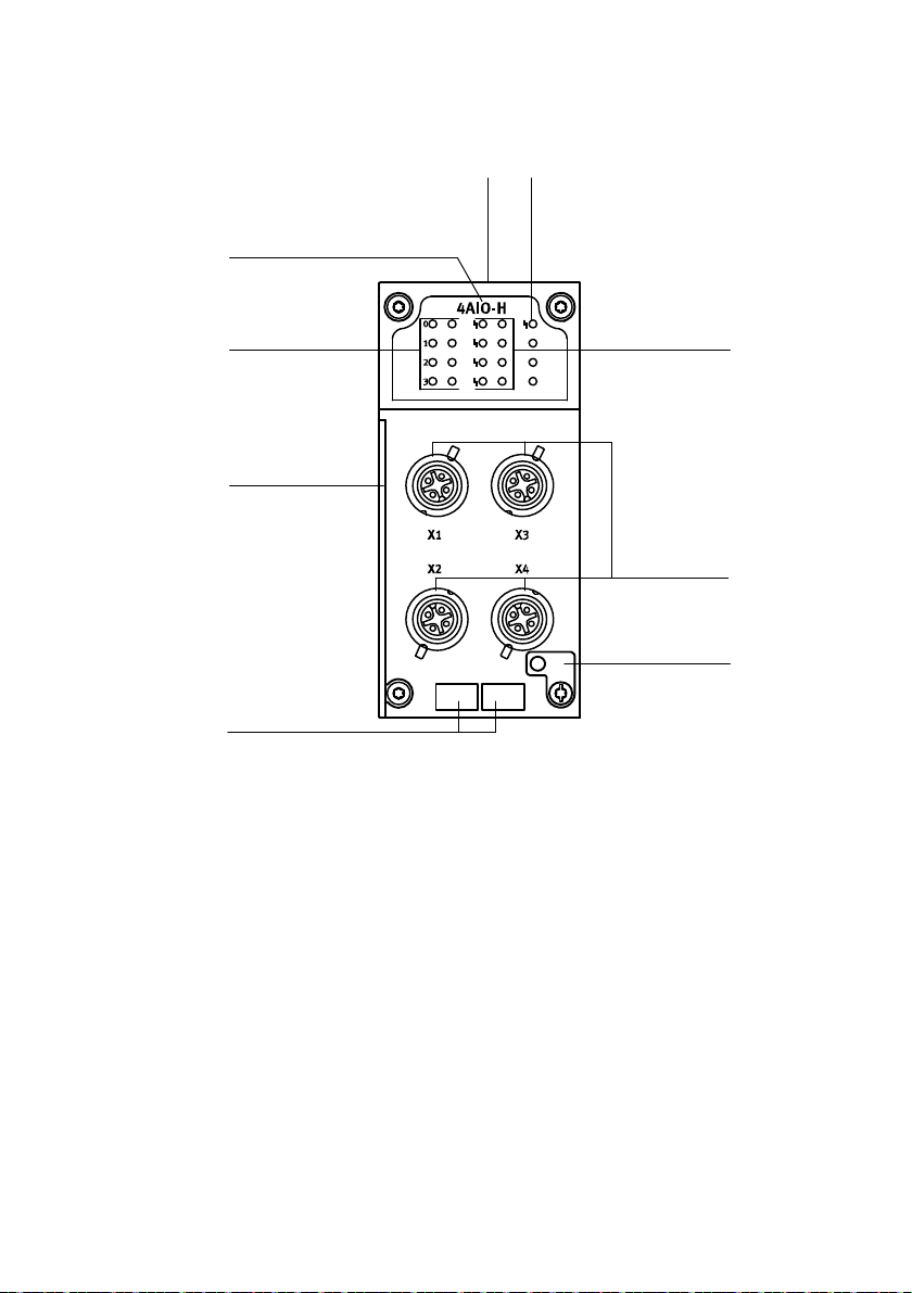
5.3.2 Connection and display components
1
32
9
8
7
1 Module identifier
2 Product labelling, connection block
(on the top side of the fibre-optic cable)
3 Module error indicator (red LED)
4 Channel error indicator (red LED)
5 Electrical connections (here: M12)
6 Earth terminal
7 Inscription labels
8 Slot for insulating plate
9 Channel status indicator (1 LED per channel)
LED 0 … 3 (green): input
LED 0 … 3 (yellow): output
Fig. 3 Connection and display components – example of M12 connection block
4
5
6
Festo – CPX-4AE-4AA-H – 2017-12 English 11
Page 12
CPX-4AE-4AA-H
5.4 Product-specific terms and abbreviations
Term/
abbreviation
O Output
CPX terminal (-P) Modular electrical terminal which is particularly suitable for use in the process
HART Highway Addressable Remote Transducer
HART protocol Bidirectional, platform-independent data transfer protocol that permits access
I Input
PII Process image of inputs è process image.
PIO Process image of outputs è process image.
Process image The process image is part of a controller's system memory. At the start of the
PV Primary Value
QV Quaternary Value
SV Secondary Value
TV Tertiary Value
Tab. 7 Product-specific terms and abbreviations
Significance
industry (intrinsically safe electronics modules available)
to the data of intelligent field devices
cyclical program, the signal states of the input modules are transferred to the
process image for the inputs (PII). At the end of the cyclical program, the
process image for the outputs (PIO) is transferred to the output modules as
asignal status.
12 Festo – CPX-4AE-4AA-H – 2017-12 English
Page 13
CPX-4AE-4AA-H
6 Mounting
6.1 General instructions
CPX terminals are delivered in mounted form. For expansion or conversion, remounting may be
necessary:
– Dismounting or remounting of the connection block when exchanging the connection technology
– Dismounting and remounting of the electronics module by setting the DIL switches or exchanging
the electronics module
Arrangement on terminal CPX
For further information on the arrangement of the modules, observe the description of
system CPX and the module documents è Chap. 1.1.
6.2 Mechanically coding the connection block
To prevent an incorrect allocation of the connection block to the electronics module, this connection
can be mechanically coded.
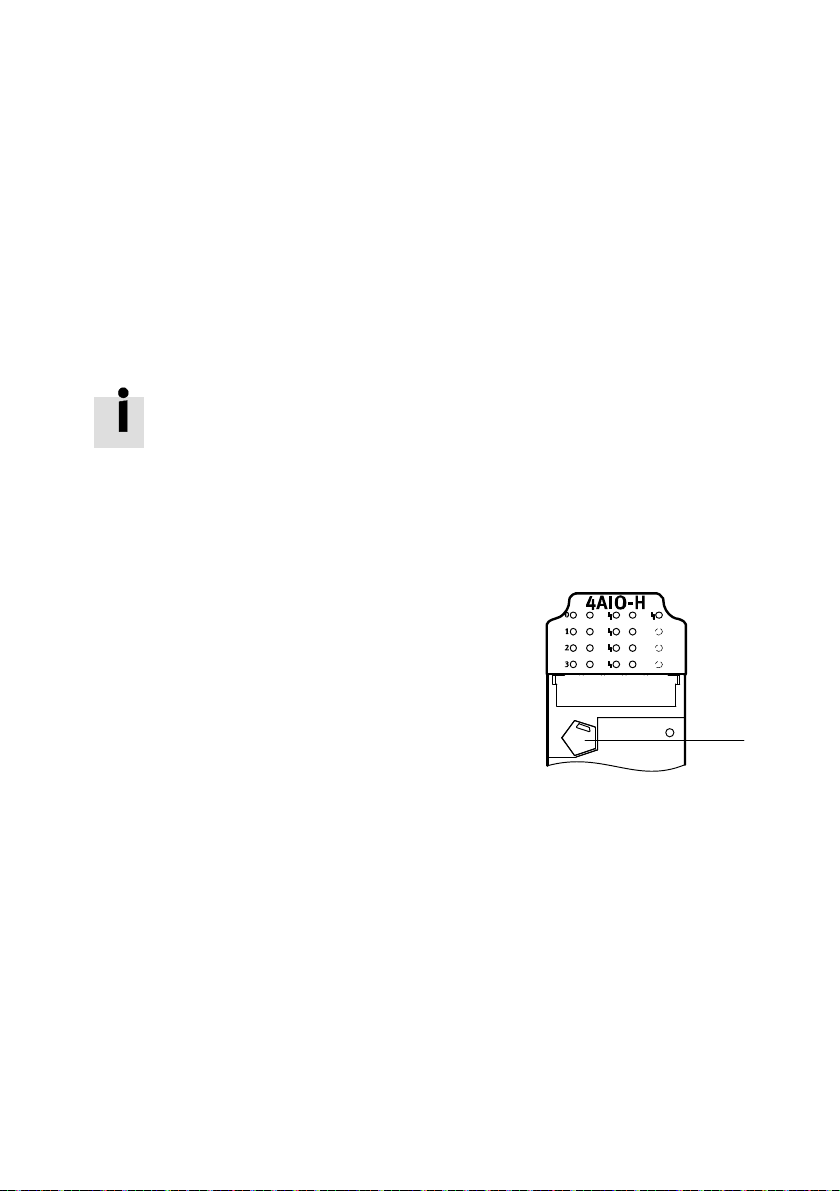
– The electronics module has a permanently
attached coding pin at the top è Fig. 4, 1.
– The connection block has a recess for a coding
piece at the bottom.
– Connection block in pre-assembled CPX
terminals are mechanically coded at the
factory.
1
Fig. 4 Coding pin on the electronics module
Festo – CPX-4AE-4AA-H – 2017-12 English 13
Page 14
CPX-4AE-4AA-H
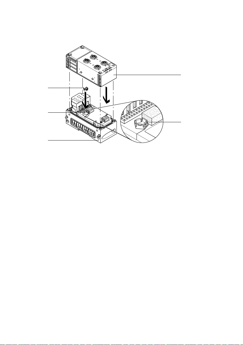
Inserting the coding piece into the connection block
5
4
3
1
2
1 Connection block
2 Latching hook on coding piece
4 Coding pin
5 Coding piece
3 Interlinking block with electronics module
Fig. 5 Mechanical coding of connection block – example
1. Lay the interlinking block and electronics module 3 horizontally on a flat surface.
2. With the latching hook 2 facing upward, place the coding piece on the coding pin 4.
3. Align the plug connector of the connection block with the plug connector of the electronics module.
4. Push the connection block onto the electronics module without tilting until the coding piece in the
connection block engages.
14 Festo – CPX-4AE-4AA-H – 2017-12 English
Page 15
CPX-4AE-4AA-H
Removing a coding piece from the connection block
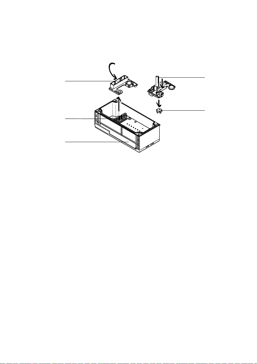
To change the device configuration, the coding piece might have to be removed from the connection
block.
1
5
4
1 Cover with interlock
2 Tool (e.g. pin)
4 Connection block
5 Plug connectors
3 Coding piece
Fig. 6 Remove the coding piece
1. Lay the connection block 4 on a flat surface, top side first.
2. Unlock and remove the cover 1.
3. Press out the coding piece 3 using a suitable tool 2.
4. Push the cover onto the plug connector of the connection block 5.
2
3
Festo – CPX-4AE-4AA-H – 2017-12 English 15
Page 16
CPX-4AE-4AA-H
6.3 Mounting the electronics module and connection block
Requirements
– Supply voltage is switched off.
– The interlinking block is clean and free of foreign matter.
– DIL switches are set è Tab. 8.
1
7
6
5
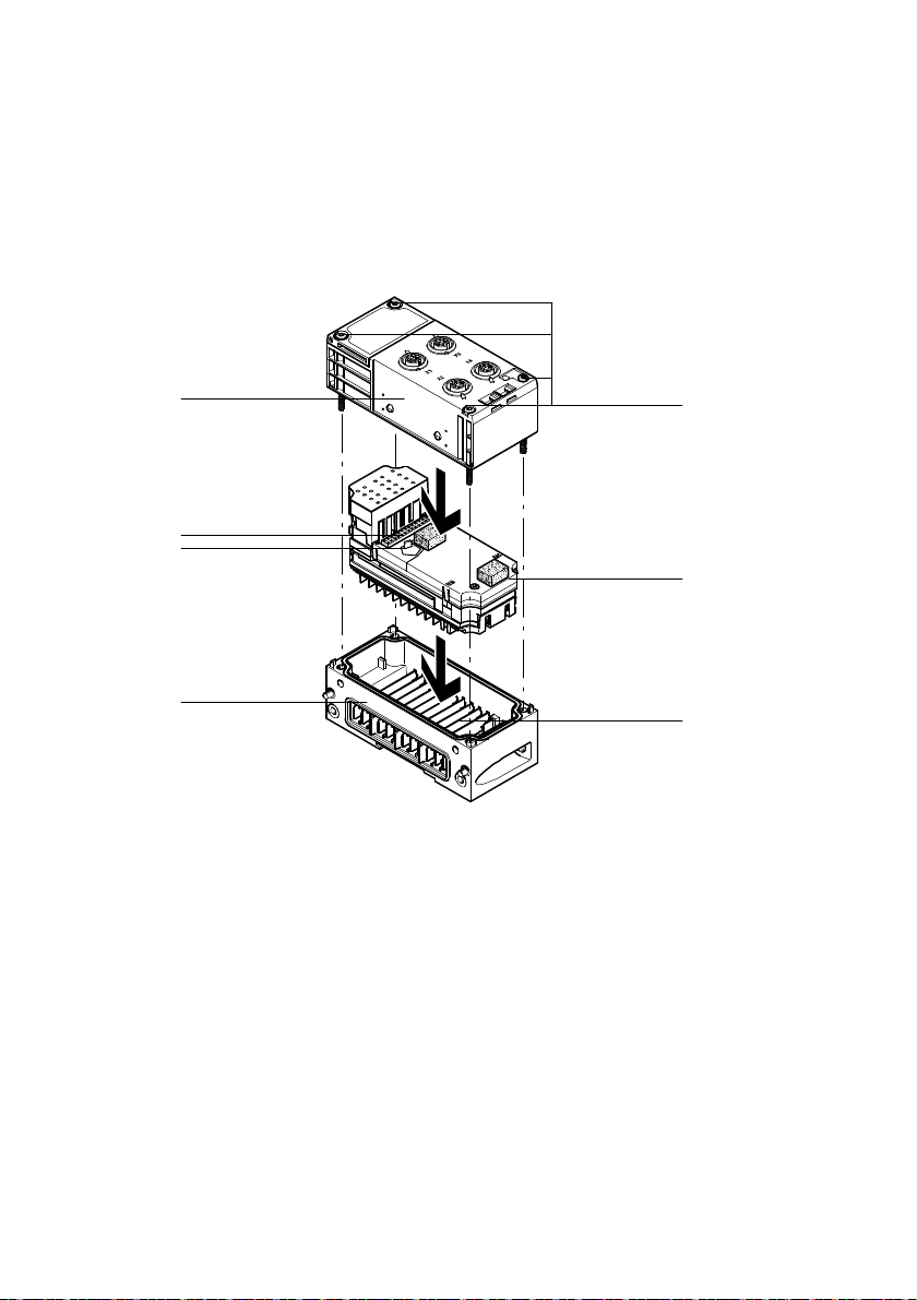
1 Connection block
2 Screws (Torx T10)
3 Electronics module
4 Contact rails
Fig. 7 Mounting of the electronics module and connection block – example
5 Interlinking block
6 Coding pin
7 Plug connectors
2
3
4
16 Festo – CPX-4AE-4AA-H – 2017-12 English
Page 17

CPX-4AE-4AA-H
Mounting the electronics module and connection block
Note
If threads are damaged or seals are defective, the device cannot achieve its specified
IPdegree of protection.
Before mounting, check the seals and thread.
Replace damaged parts.
1. Check seal and seal surfaces. Replace damaged parts.
2. Place the electronics module in the interlinking block without tilting.
3. Press on the electronics module to the limit stop.
4. Align the connection block on the interlinking block with the electronics module.
5. Push the connection block onto the interlinking block without tilting.
6. Insert the screws and tighten them crosswise:
– Plastic interlinking block: thread-cutting screws
– Metal interlinking block: screws with metric thread
– Tightening torque 0.9 … 1.1 Nm
6.4 Dismounting the electronics module and connection block
1. Switch off the power supply of the entire terminal CPX:
– Compressed air
– Operating voltage for electronics and sensors
– Load voltage of valves
2. Loosen the screws of the connection block.
3. Pull the connection block out of the plug connector of the electronics module without tilting.
4. Pull the electronics module out of the contact rails of the interlinking block without tilting.
Festo – CPX-4AE-4AA-H – 2017-12 English 17
Page 18
CPX-4AE-4AA-H
7 Installation
7.1 Prerequisites for installation
Switch off the power supply of the entire terminal CPX:
– Compressed air
– Operating voltage for electronics and sensors
– Load voltage of valves
7.2 Power supply
The operating and load voltage supply is fed through interlinking blocks or end plates
(Protective Extra-Low Voltage, PELV) è Description of system CPX.
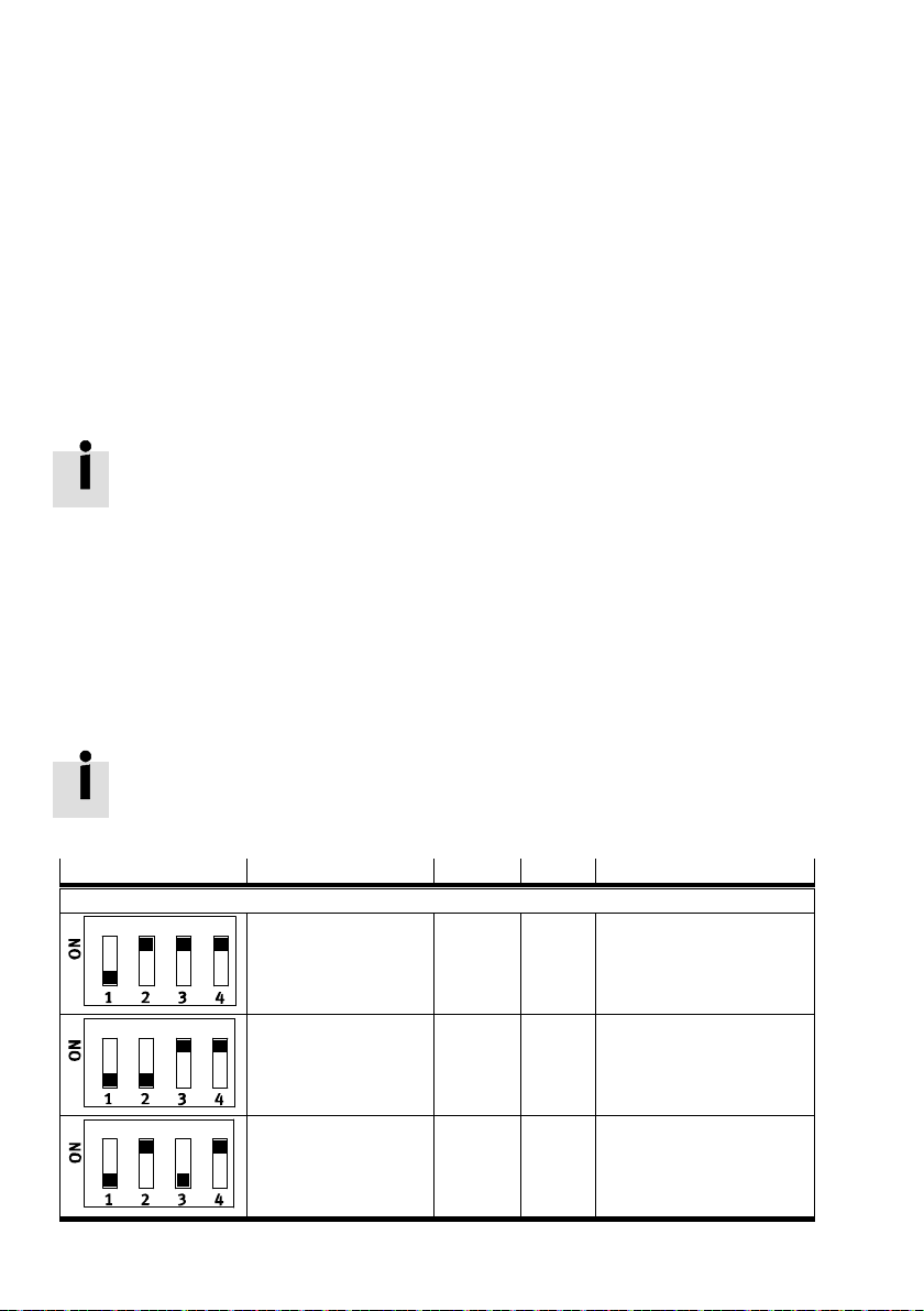
7.3 Changing the configuration of the analogue current channels
(DILswitches)
Description of the switch positions
Using the DIL switches, the following analogue current channel functions can be configured:
– Input or output channel
– Expansion of the process image by HART variables (+16 bytes)
If the configuration of the analogue current channels is changed, observe the maximum
address range of the terminal CPX – e.g. if the process image is expanded by HART
variables.
Switch setting Variant PII PIO Description
Without HART variables
4AE-H 8 bytes 0 bytes Channel 0: input
Channel 1: input
Channel 2: input
Channel 3: input
3AE1AA-H 6 bytes 2 bytes Channel 0: input
Channel 1: input
Channel 2: input
Channel 3: output
2AE2AA-H 4 bytes 4 bytes Channel 0: input
Channel 1: input
Channel 2: output
Channel 3: output
18 Festo – CPX-4AE-4AA-H – 2017-12 English
Page 19
CPX-4AE-4AA-H
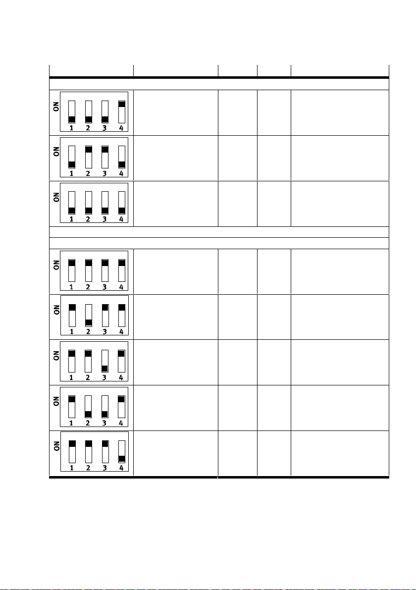
Switch setting DescriptionPIOPIIVariant
Without HART variables
1AE3AA-H 2 bytes 6 bytes Channel 0: input
4AA-H 0 bytes 8 bytes Channel 0: output
Reserved for test mode – – –
With HART variables
4AE-H + 4HV 24 bytes 0 bytes Channel 0: input
3AE1AA-H + 4HV 22 bytes 2 bytes Channel 0: input
2AE2AA-H + 4HV 20 bytes 4 bytes Channel 0: input
1AE3AA-H + 4HV 18 bytes 6 bytes Channel 0: input
4AA-H + 4HV 16 bytes 8 bytes Channel 0: output
Tab. 8 DIL switch settings
Channel 1: output
Channel 2: output
Channel 3: output
Channel 1: output
Channel 2: output
Channel 3: output
Channel 1: input
Channel 2: input
Channel 3: input
Channel 1: input
Channel 2: input
Channel 3: output
Channel 1: input
Channel 2: output
Channel 3: output
Channel 1: output
Channel 2: output
Channel 3: output
Channel 1: output
Channel 2: output
Channel 3: output
Festo – CPX-4AE-4AA-H – 2017-12 English 19
Page 20
CPX-4AE-4AA-H
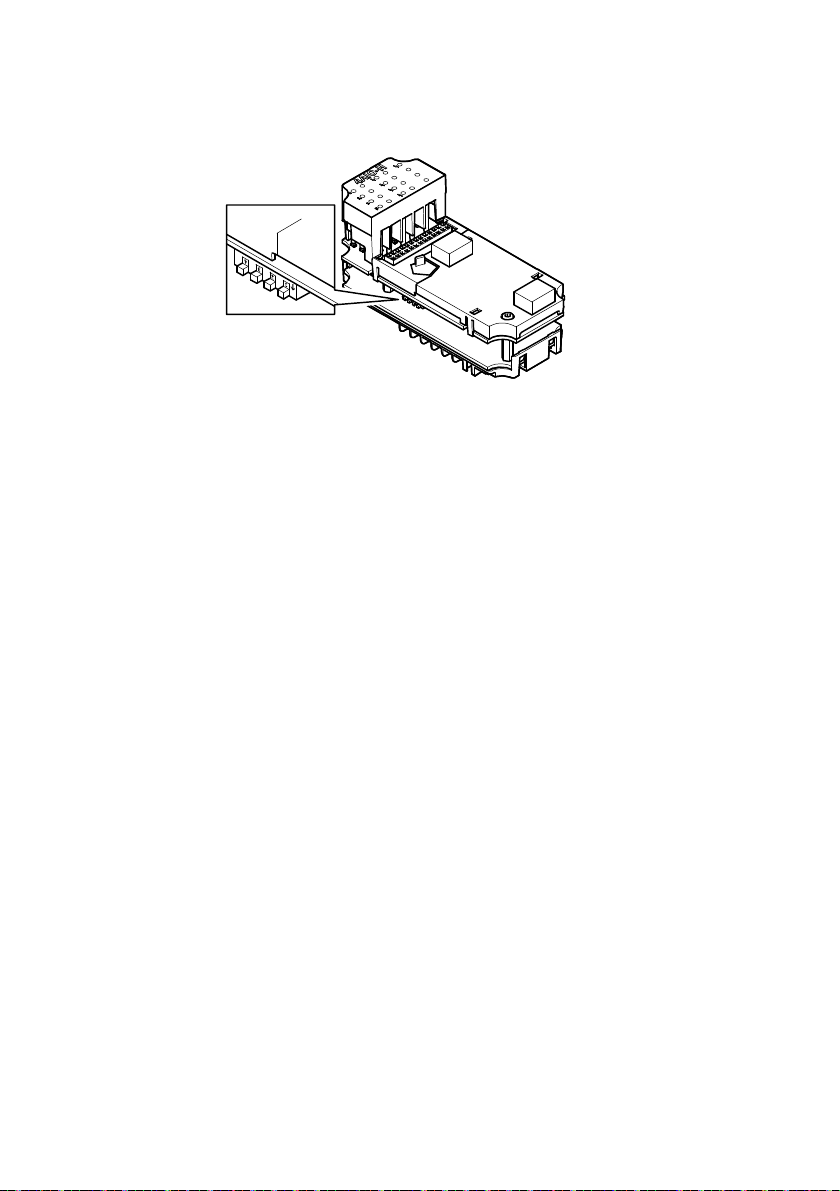
Setting the DIL switches
Fig. 8 DIL switches for the configuration of the analogue current channels
1. Switch off the power supply of the entire terminal CPX:
– Compressed air
– Operating voltage for electronics and sensors
– Load voltage of valves
2. Loosen the screws of the connection block.
3. Pull the connection block out of the plug connector of the electronics module without tilting.
4. Set the DIL switches on the electronics module.
5. Mount the connection block è Chap. 6.3.
è The process image becomes effective after switching on the power supply.
20 Festo – CPX-4AE-4AA-H – 2017-12 English
Page 21
CPX-4AE-4AA-H
7.4 Electrical system
7.4.1 Notices regarding the cable connection
For the connection of HART field devices: observe the wiring requirements according to the
HARTspecification.
Observe the maximum line lengths for the connection of field devices: 500 m.
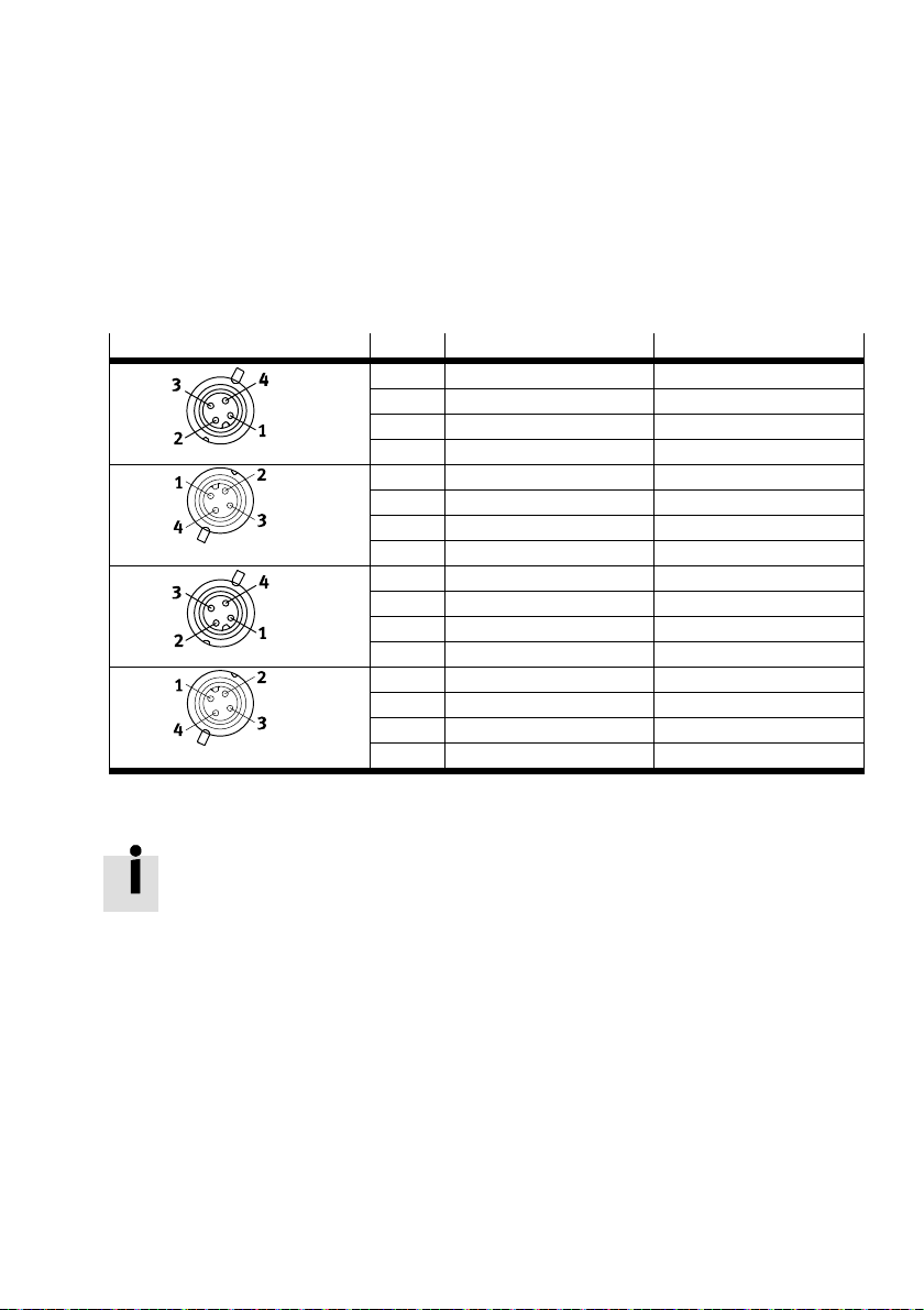
7.4.2 Attaching connecting cables to the connection block M12
Socket contact M12 Pin
X1
X2
X3
X4
1) Connection and display components è Fig. 3.
Tab. 9 Pin allocation on connection block CPX-P-AB-4XM12-4POL
1)
Function Signal
X1.1 24 V
X1.2 0 V
/IO0 AOUT0
SEN
SEN
XGN D
X1.3 II0 AIN0
X1.4 0 V
X2.1 24 V
X2.2 0 V
SEN
/IO1 AOUT1
SEN
SEN
XGN D
XGN D
X2.3 II1 AIn1
X2.4 0 V
X3.1 24 V
X3.2 0 V
SEN
/IO2 AOUT2
SEN
SEN
XGN D
XGN D
X3.3 II2 AIN2
X3.4 0 V
X4.1 24 V
X4.2 0 V
SEN
/IO3 AOUT3
SEN
SEN
XGN D
XGN D
X4.3 II3 AIN3
X4.4 0 V
SEN
XGN D
The metal thread of socket contact M12 is internally connected to the earth terminal
ofterminal CPX and can be used as a screen connection.
Only use suitable plug connectors è www.festo.com/catalogue
Seal unused connections with protective caps ISK-M12 è Accessories.
Festo – CPX-4AE-4AA-H – 2017-12 English 21
Page 22
CPX-4AE-4AA-H
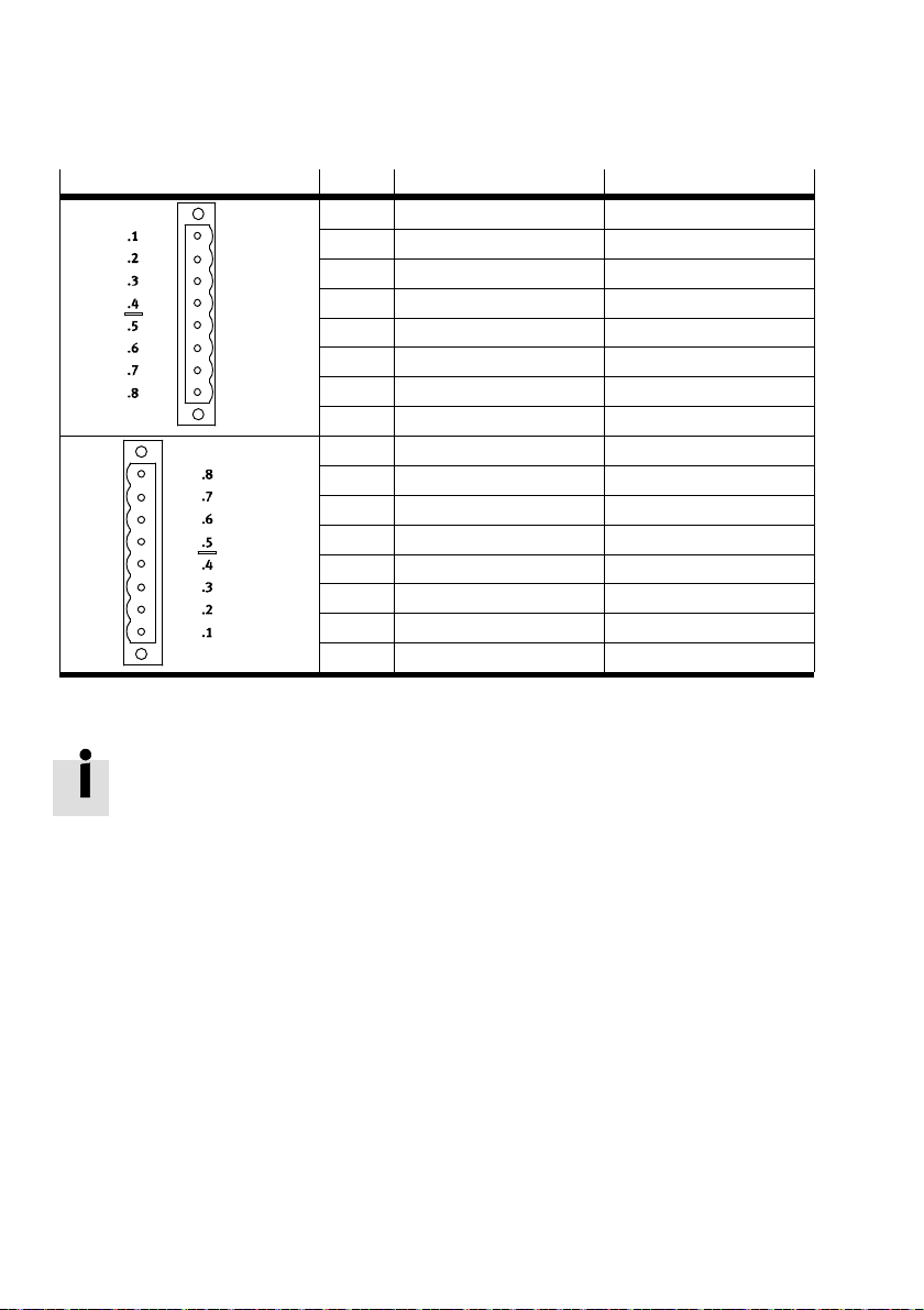
7.4.3 Attaching connecting cables to the terminal connection block
Connection block
Pin
X1.1 24 V
X1.2 0 V
Function Signal
/IO0 AOUT0
SEN
SEN
1)
X1.3 II0 AIN0
X1
X1.4 0 V
X1.5 24 V
X1.6 0 V
SEN
/IO1 AOUT1
SEN
SEN
X1.7 II1 AIn1
X1.8 0 V
X2.1 24 V
X2.2 0 V
SEN
/IO2 AOUT2
SEN
SEN
X2.3 II2 AIN2
X2
X2.4 0 V
X2.5 24 V
X2.6 0 V
SEN
/IO3 AOUT3
SEN
SEN
X2.7 II3 AIN3
X2.8 0 V
1) Connection and display components è Fig. 3.
SEN
Tab. 10 Pin allocation on terminal connection block CPX-P-AB-2XKL-8POL
XGN D
XGN D
XGN D
XGN D
XGN D
XGN D
XGN D
XGN D
Connection blocks CPX-P-AB-2XKL-8POL do not feature a connection for the cable
screening.
Set up the screening or equipotential bonding separately.
22 Festo – CPX-4AE-4AA-H – 2017-12 English
Page 23
CPX-4AE-4AA-H
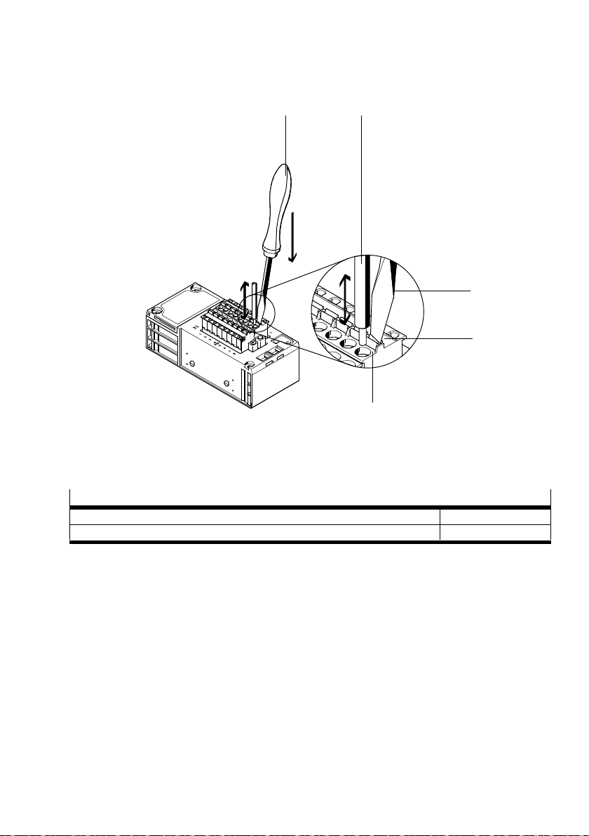
Connecting the plug connector in spring-loaded terminal technology
21
4
1
3
1 Screwdriver, blade 2.5 x 0.4 mm
2 Cable
3 Unlocking
4 Terminal opening
Fig. 9 Connection of the connecting cable in spring-loaded terminal technology
Spring-loaded terminal NECU-L3G8-C1-...
Conductor cross section with wire end sleeve [mm2] 0.25 … 2.5
Strip length [mm] 10
Tab. 11 Specifications for spring-loaded terminal
Only use suitable terminal strips è www.festo.com/catalogue
Connect only one conductor per spring-loaded terminal.
With a screwdriver, press the unlocking pin and insert the conductor end with the wire end sleeve
into the terminal opening to the limit stop.
Festo – CPX-4AE-4AA-H – 2017-12 English 23
Page 24
CPX-4AE-4AA-H
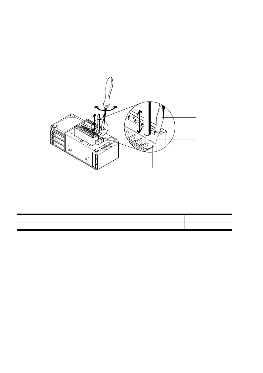
Connecting the plug connector in screw terminal technology
12
1
3
4
1 Screwdriver
2 Cable
3 Screw terminal
4 Terminal opening
Fig. 10 Connection of the connecting cable in screw terminal technology
Screw terminal NECU-L3G8-C2-...
Conductor cross section with wire end sleeve [mm2] 0.25 … 2.5
Strip length [mm] 10
Tab. 12 Specifications for screw terminal
Only use suitable terminal strips è www.festo.com/catalogue
Connect only one conductor per screw terminal.
Loosen the screw terminal, insert the conductor end with wire end sleeve and tighten the
screwterminal (tightening torque: 0.5 … 0.6 Nm).
24 Festo – CPX-4AE-4AA-H – 2017-12 English
Page 25
CPX-4AE-4AA-H
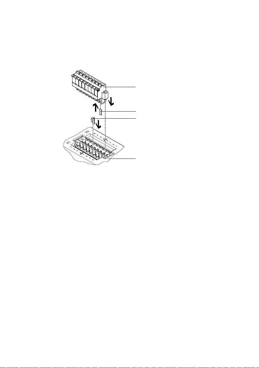
7.4.4 Mechanically coding the terminal connection
The terminal connection can be mechanically coded with a coding system.
The coding system is optionally available è www.festo.com/catalogue.
Recommendation: provide each contact with a coding element.
1
2
3
4
1 Terminal strip
2 Coding profile for the groove of the
terminalstrip
Fig. 11 Use of the mechanical coding system
3 Coding tab for the recess on the box header
4 Box header
Festo – CPX-4AE-4AA-H – 2017-12 English 25
Page 26
CPX-4AE-4AA-H
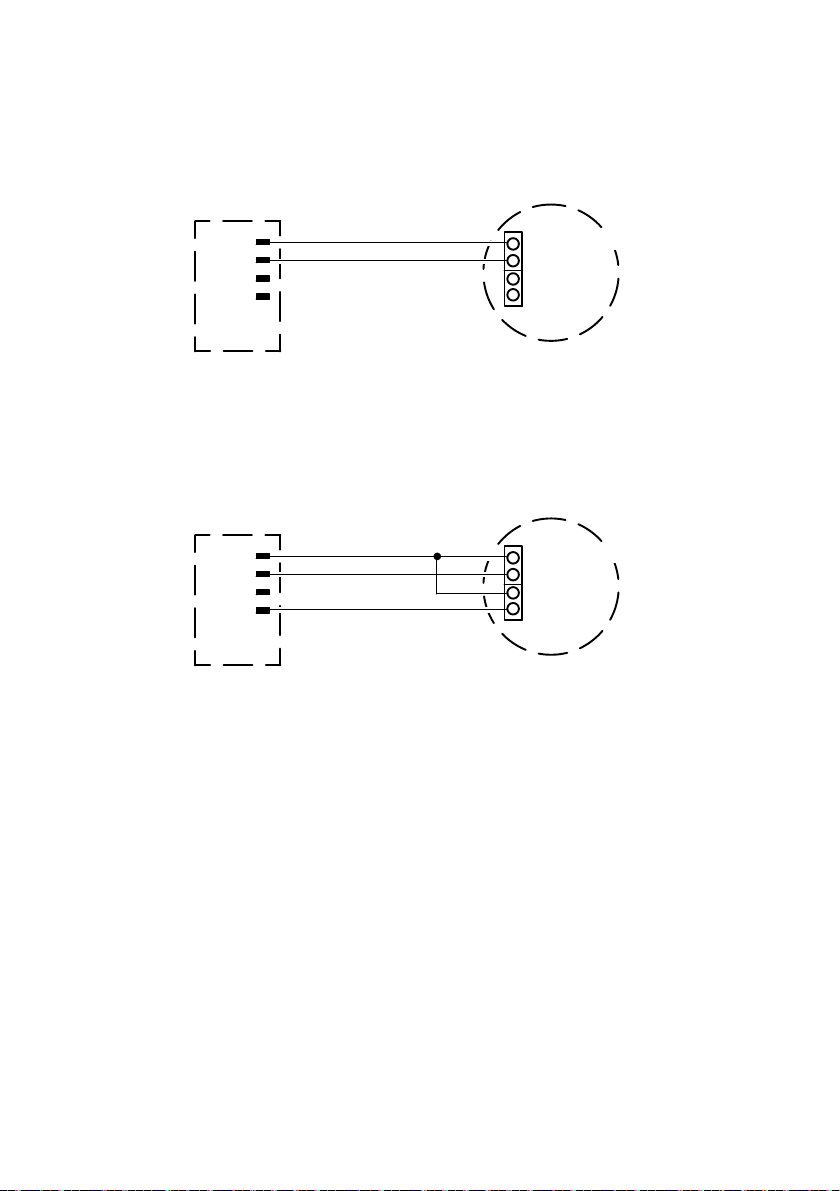
7.5 Connection scenarios
7.5.1 2-wire connection of passive HART transmitters
24 V
SEN
IIx
+ 4 … 20 mA HART
–
L+
L–
2
1
1 HART input module: active 2 HART transmitter: passive
Fig. 12 2-wire connection of a passive HART transmitter
Power supply for the HART transmitter, HART communication and actual values in the same circuit
7.5.2 3-wire connection of passive HART transmitters
24 V
SEN
IIx
+ 4 … 20 mA HART
–
L+
0 V
SEN
L–
2
1
1 HART input module: active 2 HART transmitter: passive
Fig. 13 3-wire connection of a passive HART transmitter
Power supply for the HART transmitter via the HART input module
26 Festo – CPX-4AE-4AA-H – 2017-12 English
Page 27
CPX-4AE-4AA-H
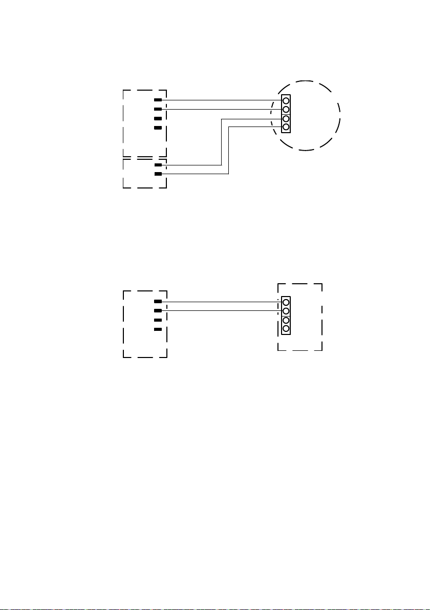
7.5.3 4-wire connection of active HART transmitters
IIx
GND
+ 4 … 20 mA HART
–
L+
L–
2
1
3
1 HART input module: passive
3 Auxiliary energy
2 HART transmitter: active
Fig. 14 4-wire connection of an active HART transmitter
Power supply for the HART transmitter via the auxiliary energy
7.5.4 2-wire connection of passive HART actuators
AOUTx
0 V
SEN
+ 4 … 20 mA HART
–
L+
L–
1
2
1 HART output module: active 2 HART actuator: passive
Fig. 15 2-wire connection of a passive HART actuator
Power supply for the HART actuator, HART communication and setpoint in the same circuit
Festo – CPX-4AE-4AA-H – 2017-12 English 27
Page 28
CPX-4AE-4AA-H
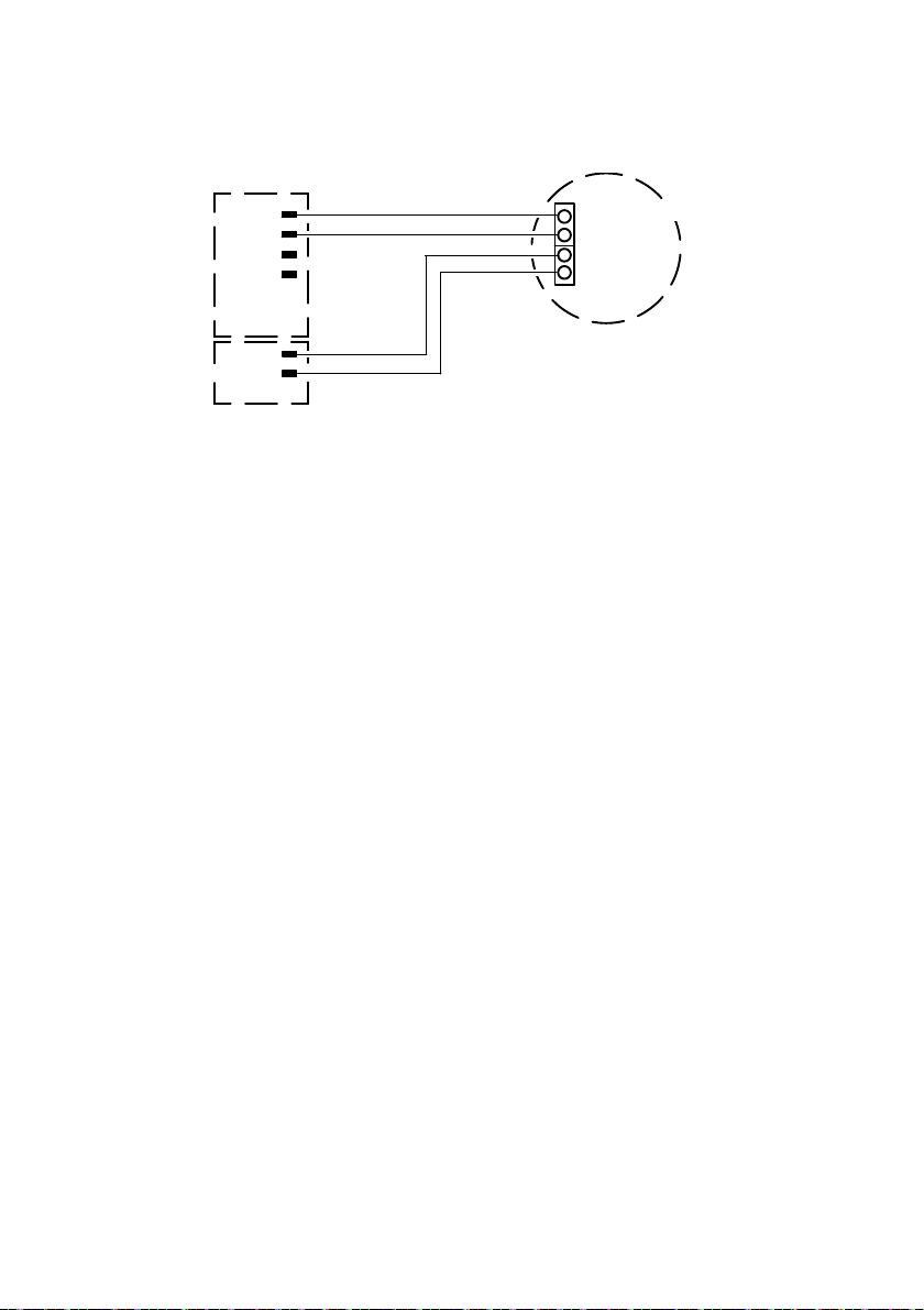
7.5.5 4-wire connection of active HART actuators
AOUTx
GND
1
3
1 HART output module: passive
3 Auxiliary energy
2 HART actuator: active
Fig. 16 4-wire connection of an active HART actuator
Power supply for the HART actuator via the auxiliary energy
+ 4 … 20 mA HART
–
L+
L–
2
28 Festo – CPX-4AE-4AA-H – 2017-12 English
Page 29
CPX-4AE-4AA-H
8 Commissioning
8.1 Requirements for commissioning
– DIL switches for the configuration of the analogue current channels are set è Chap. 7.3.
– The analogue module is completely installed into terminal CPX and connected.
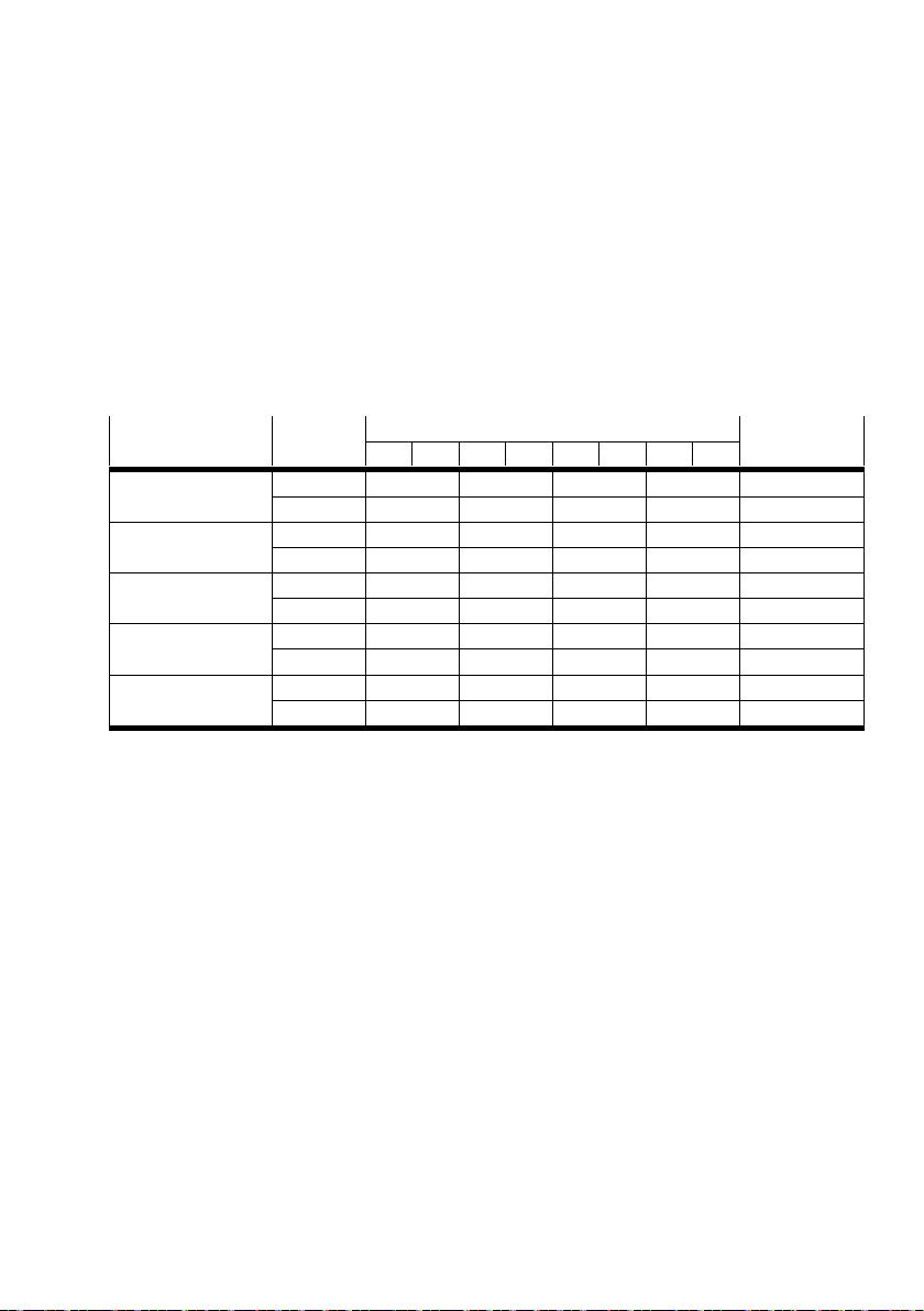
8.2 Process image and address space allocation
For each terminal CPX, 64 bytes are available for the cyclic data exchange of the inputs and outputs.
Variant I/O Contents of bytes
7 6 5 4 3 2 1 0
4AE-H Input IW CH3 IW CH2 IW CH1 IW CH0 8 bytes
Output – – – – 0 bytes
3AE1AA-H Input – IW CH2 IW CH1 IW CH0 6 bytes
Output – – – SW CH3 2 bytes
2AE2AA-H Input – – IW CH1 IW CH0 4 bytes
Output – – SW CH3 SW CH2 4 bytes
1AE3AA-H Input – – – IW CH0 2 bytes
Output – SW CH3 SW CH2 SW CH1 6 bytes
4AA-H Input – – – – 0 bytes
Output SW CH3 SW CH2 SW CH1 SW CH0 8 bytes
1) IW CH0 = actual value of channel 0 (input), SW CH1 = setpoint value of channel 1 (output), etc.
Tab. 13 Process image for variants without HART variables
1)
Address space
allocation
Festo – CPX-4AE-4AA-H – 2017-12 English 29
Page 30
CPX-4AE-4AA-H
Variant I/O Contents of bytes
1)
2223202118191617141512131011896745230
1
4AE-H
+ 4HV
Input HV4 HV3 HV2 HV1 IW
CH3IWCH2IWCH1IWCH0
Output – – – – – – 0 bytes
3AE1AA-H
+ 4HV
Input – HV4 HV3 HV2 HV1 IW
CH2IWCH1IWCH0
Output – – – – – – SW
CH3
2AE2AA-H
+ 4HV
Input – HV4 HV3 HV2 HV1 IW
CH1IWCH0
Output – – – – – SW
CH3SWCH2
1AE3AA-H
+ 4HV
Input – HV4 HV3 HV2 HV1 IW
CH0
Output – – – – SW
CH3SWCH2SWCH1
4AA-H
Input – HV4 HV3 HV2 HV1 16 bytes
+ 4HV
Output – – – SW
CH3SWCH2SWCH1SWCH0
1) IW CH0 = actual value of channel 0 (input), SW CH1 = setpoint value of channel 1 (output), etc.; HV= HART variable
Tab. 14 Process image for variants with HART variables
Address
space
allocation
24 bytes
22 bytes
2 bytes
20 bytes
4 bytes
18 bytes
6 bytes
8 bytes
8.3 HART variables
The process image can be expanded by a total of 4 HART variables è Tab. 14.
– Quantity per HART variable: 4 bytes
– Data format: 16-bit value
Depending on the higher-order control system, low byte and high byte may be organised differently.
– If an invalid value has been determined, 0xFFFF is transmitted.
– Determination of the HART variables to be transferred during parameterisation è Chap. 8.4.
30 Festo – CPX-4AE-4AA-H – 2017-12 English
Page 31

CPX-4AE-4AA-H
8.4 Parameterisation
The CPX terminal and the module described here can be parameterised with the operator unit
(CPX-MMI), the Festo Maintenance Tool (CPX-FMT) software or the higher-level system.
8.4.1 Recommended parameterisation sequence
Changed parameters are not valid until a complete check and saving procedure have been performed
(max.30 ms).
Until saving and in case of invalid values, the previous settings apply.
To prevent parameterisation errors, observe the following sequence when changing the
parameterisation:
1. Activate the “Module CPX monitoring, parameterisation of error control” module parameter
è Tab. 16.
2. Activate the “Channel 0 … 3 monitoring” for the channel to be changed è Tab. 19.
3. Set the data format è Tab. 18.
4. Set the limit values for each channel è Tab. 20, Tab. 21.
– When the upper limit value is positive, set the upper limit value before setting the lower
limitvalue.
– If the upper limit value is negative, set the lower limit value before setting the upper limit value.
Further information on parameterisation è Description of system CPX and description
ofthe bus node.
Festo – CPX-4AE-4AA-H – 2017-12 English 31
Page 32
CPX-4AE-4AA-H
8.4.2 Overview of parameters
Tab. 15 shows an overview of the parameters contained in the analogue module.
Detailed parameter description è Chap. 8.4.3.
Function number Bit Parameter Presetting Details
4828 + m* 64 + 0 0 Monitoring of short circuit/overload Active Tab. 16
1 … 6 Reserved –
7 Monitoring of parameterisation errors Active
4828 + m* 64 + 1 0 Behaviour after short circuit/overload Automatic
Tab. 17
return
1 … 7 Reserved –
4828 + m* 64 + 2 0 … 7 Reserved –
4828 + m* 64 + 3 0 … 7 Reserved –
4828 + m* 64 + 4 0 … 7 Reserved –
4828 + m* 64 + 5 0 … 7 Reserved –
4828 + m* 64 + 6 0 Data format Sign + 15 bits Ta b. 18
1 … 3 Reserved –
4 Monitoring according to NAMUR NE43 Inactive
5 … 6 Reserved –
7 Reserved –
4828 + m* 64 + 7 … 10 0 … 7 Monitoring of channel 0 … 3 – Tab. 19
4828 + m* 64 + 11 … 18 0 … 7 Lower limit value of channel 0 … 3 -27648 Tab . 2 0
4828 + m* 64 + 19 … 26 0 … 7 Upper limit value of channel 0 … 3 27648 Tab. 21
4828 + m* 64 + 27 0 … 3 Number of HART repetitions 0 Tab. 22
4 … 7 Reserved –
4828 + m* 64 + 28 … 29 0 … 7 Limit monitoring hysteresis of
0 Tab. 23
channel0 … 3
4828 + m* 64 + 30 0 … 7 Signal range of channel 0 … 3 Inactive Ta b. 24
4828 + m* 64 + 31 0 … 7 Smoothing factor Inactive Ta b. 26
4828 + m* 64 + 32
0 … 7 IEEE variable 0 … 3 PV, channel 0 Tab. 28
4828 + m* 64 + 33
Access via protocol-specific
functions
Fail-safe of channel 0 … 3 – Ta b. 31
Idle mode of channel 0 … 3 – Ta b. 32
Forcing of channel 0 … 3 – Tab. 3 3
Tab. 15 Overview of the module and channel parameters
32 Festo – CPX-4AE-4AA-H – 2017-12 English
Page 33

CPX-4AE-4AA-H
8.4.3 Description of the module and channel parameters
Module parameters: monitoring of short circuit/overload, monitoring of parameter errors
Function
4828 + m* 64 + 0 m = module number (0 … 47)
number
Description Monitoring of the analogue module for the following errors:
– Short circuit or overload
– Parameterisation errors for the lower and upper limit value, hysteresis
The monitoring of the errors can be individually activated or deactivated.
Active monitoring has the following effect:
– Error message at the CPX bus nodes
– The error LED is illuminated è Fig. 18.
SCS monitoring
The SCS monitoring can be activated for the entire terminal CPX è Description of
system CPX.
Monitoring of parameterisation errors
Prerequisites for the monitoring of channel-specific parameterisation:
– The “Monitoring of parameterisation errors” module parameter is active.
– The “Monitoring of parameterisation errors” channel parameter is
active è Tab. 19.
Allocation Bit 0: SCS monitoring (sensor supply short-circuit/overload)
Bit 1 … 6: Reserved
Bit 7: Monitoring of parameterisation errors
Values Bit 0, 7: 0 = Inactive
1 = Active (default)
Tab. 16 Description of the “Module CPX monitoring, parameterisation of error control” module
parameter
Festo – CPX-4AE-4AA-H – 2017-12 English 33
Page 34

CPX-4AE-4AA-H
Module parameter: behaviour after short circuit/overload
Function
4828 + m* 64 + 1 m = module number (0 … 47)
number
Description Determination of the behaviour of the power supply after short circuit or overload
inan input or output
Allocation Bit 0: Behaviour after short circuit/overload
Bit 1 … 7: Reserved
Values Bit 0: 0 = Leave voltage deactivated
For voltage recovery, “Power On” or a reparameterisation of the
module parameter is required.
1 = Restart voltage
The voltage is restarted automatically after the cause of the error
is remedied (presetting).
Tab. 17 Description of the “Behaviour after short circuit/overload” module parameter
Module parameter: data format, monitoring according to NAMUR NE43
Function
4828 + m* 64 + 6 m = module number (0 … 47)
number
Description Setting of the data format
Activation of monitoring according to NAMUR NE43:
– Monitoring effective for signal range 4 … 20 mA (with and without HART)
– Error message if the input value undershoots or exceeds the limit values
according to NAMUR NE43
Allocation Bit 0: Data format setting
Bit 1 … 3: Reserved
Bit 4: Monitoring according to NAMUR NE43
Bit 7: Reserved
Values Bit 0: 0 = Sign + 15 bits (presetting)
1 = Linear scaling
Bit 4: 0 = Inactive (presetting)
1 = Active
Tab. 18 Description of the “Data format, monitoring according to NAMUR NE43” module parameter
34 Festo – CPX-4AE-4AA-H – 2017-12 English
Page 35

CPX-4AE-4AA-H
Channel parameter: monitoring of channel 0 … 3
Function
number
4828 + m* 64 + 7
4828 + m* 64 + 8
m = module number (0 … 47)
4828 + m* 64 + 9
4828 + m* 64 + 10
Description Monitoring of the individual channels of the analogue module for the following
errors:
– Lower and upper limit value
– Wire break (idling)
– Overflow/underflow
– Parameterisation error for the lower and upper limit value
The monitoring of the errors can be individually activated or deactivated.
Active monitoring has the following effect:
– Error message at the CPX bus nodes
– The error LED is illuminated è Fig. 18.
Monitoring of lower and upper limit values
– Error message when the lower limit value is undershot è Tab. 20.
– Error message when the upper limit value is exceeded è Tab. 21.
Monitoring of wire break (idling)
– Effective for signal range 4 … 20 mA (with and without HART)
– Range of values for wire break detection at inputs è Chap.8.5.
– The wire break detection at outputs is effective only if the current value output
amounts to at least 1 mA.
Monitoring of overflow/underflow
Error message when the range of values is left è Chap.8.5.
Monitoring of parameterisation errors
Prerequisites for the monitoring of channel-specific parameterisation:
– The “Monitoring of parameterisation errors” module parameter is
active è Tab. 16.
– The “Monitoring of parameterisation errors” channel parameter is active.
Allocation Bit 0: Monitoring of lower limit value
Bit 1: Monitoring of upper limit value
Bit 2: Monitoring of wire break (idling)
Bit 3: Monitoring of overflow/underflow
Bit 4 … 6: Reserved
Bit 7: Monitoring of parameterisation errors
Values Bit 0 … 3: 0 = Inactive (presetting)
1 = Active
Bit 7: 0 = Inactive
1 = Active (default)
Tab. 19 Description of “Monitoring of channel 0 … 3” channel parameter
Festo – CPX-4AE-4AA-H – 2017-12 English 35
Page 36
CPX-4AE-4AA-H
Channel parameter: lower limit value of channel 0 … 3
Function
number
4828 + m * 64 + 11 (channel 0, low byte)
4828 + m * 64 + 13 (channel 1, low byte)
4828 + m * 64 + 15 (channel 2, low byte)
4828 + m * 64 + 17 (channel 3, low byte)
4828 + m * 64 + 12 (channel 0, high byte)
4828 + m * 64 + 14 (channel 1, high byte)
4828 + m * 64 + 16 (channel 2, high byte)
4828 + m * 64 + 18 (channel 3, high byte)
m = module number (0 … 47)
Description Setting of the lower limit value for the individual channels of the analogue
input module è Chap. 8.6.
– The lower limit value must be smaller than the upper limit value.
– The permissible values depend on the set data format è Tab. 18.
– With data format “linear scaling,” the limit values have the function of scaling
end values.
Prerequisites for the monitoring of channel-specific parameterisation:
– The “Monitoring of parameterisation errors” module parameter is
active è Tab. 16.
– The “Monitoring of parameterisation errors” channel parameter is
active è Tab. 19.
Active monitoring has the following effect:
– Invalid values are not assumed. The last valid value is kept.
Allocation Bit 0 … 7: Low byte or high byte as limit value
Values Presetting: -27648 (low byte = 0, high byte = 148)
Tab. 20 Description of “Lower limit value of channel 0 … 3” channel parameter
36 Festo – CPX-4AE-4AA-H – 2017-12 English
Page 37
CPX-4AE-4AA-H
Channel parameter: upper limit value of channel 0 … 3
Function
number
4828 + m * 64 + 19 (channel 0, low byte)
4828 + m * 64 + 21 (channel 1, low byte)
4828 + m * 64 + 23 (channel 2, low byte)
4828 + m * 64 + 25 (channel 3, low byte)
4828 + m * 64 + 20 (channel 0, high byte)
4828 + m * 64 + 22 (channel 1, high byte)
4828 + m * 64 + 24 (channel 2, high byte)
4828 + m * 64 + 26 (channel 3, high byte)
m = module number (0 … 47)
Description Setting of the upper limit value for the individual channels of the analogue input
module è Chap. 8.6.
– The upper limit value must be greater than the lower limit value.
– The permissible values depend on the set data format è Tab. 18.
– With data format “linear scaling”, the limit values have the function of scaling
end values.
Prerequisites for the monitoring of channel-specific parameterisation:
– The “Monitoring of parameterisation errors” module parameter is
active è Tab. 16.
– The “Monitoring of parameterisation errors” channel parameter is
active è Tab. 19.
Active monitoring has the following effect:
– Invalid values are not assumed. The last valid value is kept.
Allocation Bit 0 … 7: Low byte or high byte as limit value
Values Presetting: 27648 (low byte = 0, high byte = 108)
Tab. 21 Description of “Upper limit value of channel 0 … 3” channel parameter
Festo – CPX-4AE-4AA-H – 2017-12 English 37
Page 38
CPX-4AE-4AA-H
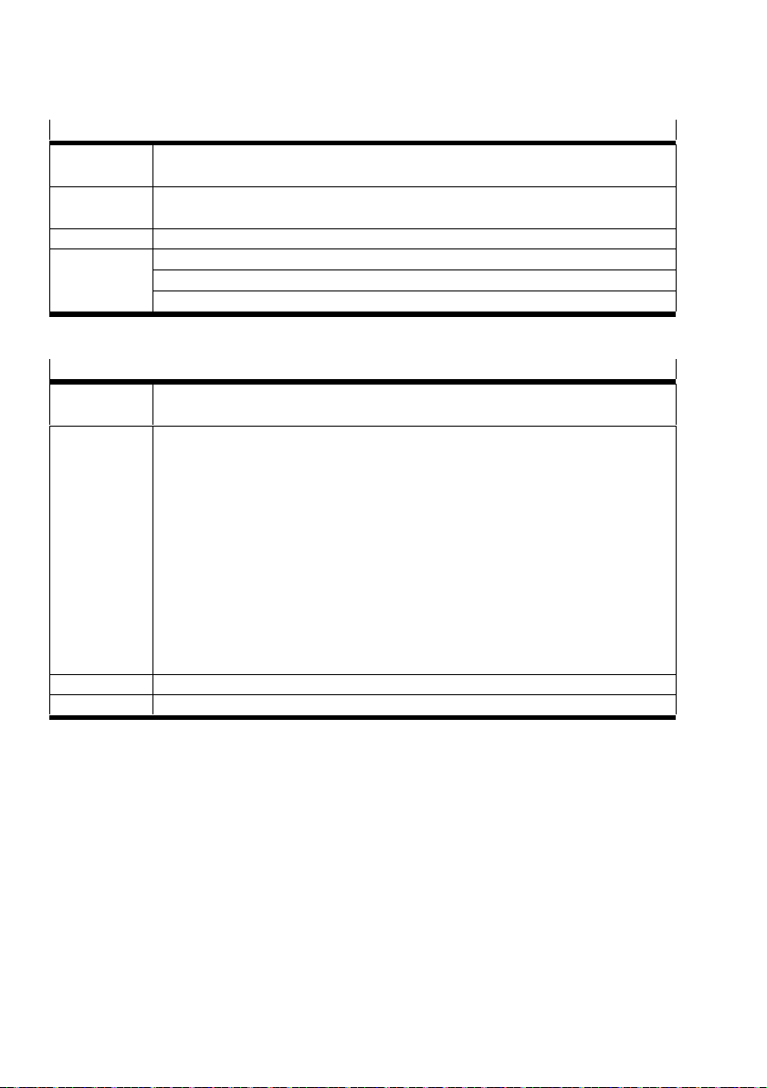
Module parameter: HART repetition
Function
4828 + m* 64 + 27 m = module number (0 … 47)
number
Description If the analogue module receives a faulty or no answer from a HART telegram sent to
the field device, the telegram is sent repeatedly according to the set value (0 … 10).
Allocation Bit 0 … 3: Number of repetitions
Values Presetting: 0
Range of values: 0 … 10
Recommended setting: 5
Tab. 22 Description of the “HART repetition” module parameter
Module parameter: limit monitoring hysteresis of channel 0 … 3
Function
number
4828 + m* 64 + 28 (low byte)
4828 + m* 64 + 29 (high byte)
m = module number (0 … 47)
Description Setting of the hysteresis behaviour for limit monitoring:
– The hysteresis applies to all channels simultaneously.
– The set hysteresis value must not be larger than the difference between the
upper and lower limit values.
– The hysteresis value is not checked during entry.
If an invalid value has been assumed, the analogue module can react
unexpectedly.
Prerequisites for the monitoring of channel-specific parameterisation:
– The “Monitoring of parameterisation errors” module parameter is
active è Tab. 16.
Active monitoring has the following effect:
– Error message (limit values and hysteresis è Fig. 17)
Allocation Bit 0 … 7: Low byte or high byte of hysteresis
Values Presetting: 0 (low byte = 0, high byte = 0)
Tab. 23 Description of the “Limit monitoring hysteresis” module parameter
38 Festo – CPX-4AE-4AA-H – 2017-12 English
Page 39
CPX-4AE-4AA-H
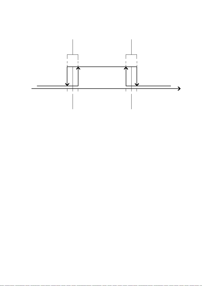
Limit values and hysteresis
11
Actual value too low:
channel error LED and
module error LED light
up red.
Error
message on
Error
message off
Error
message off
Actual value too high:
channel error LED and
module error LED light
up red.
Error
message on
Actual value
23
1 Hysteresis
3 Upper limit value
2 Lower limit value
Fig. 17 Error messages at hysteresis
The hysteresis has the same variable for both limit values and is located in the middle between the
values.
If a hysteresis is set, the analogue module behaves as follows:
– If the lower limit value is undershot by the half hysteresis value, an error message is output.
– If the lower limit value is exceeded by the half hysteresis value, an error message extinguishes.
– If the upper limit value is exceeded by the half hysteresis value, an error message is output.
– If the upper limit value is undershot by the half hysteresis value, an error message extinguishes.
Festo – CPX-4AE-4AA-H – 2017-12 English 39
Page 40
CPX-4AE-4AA-H
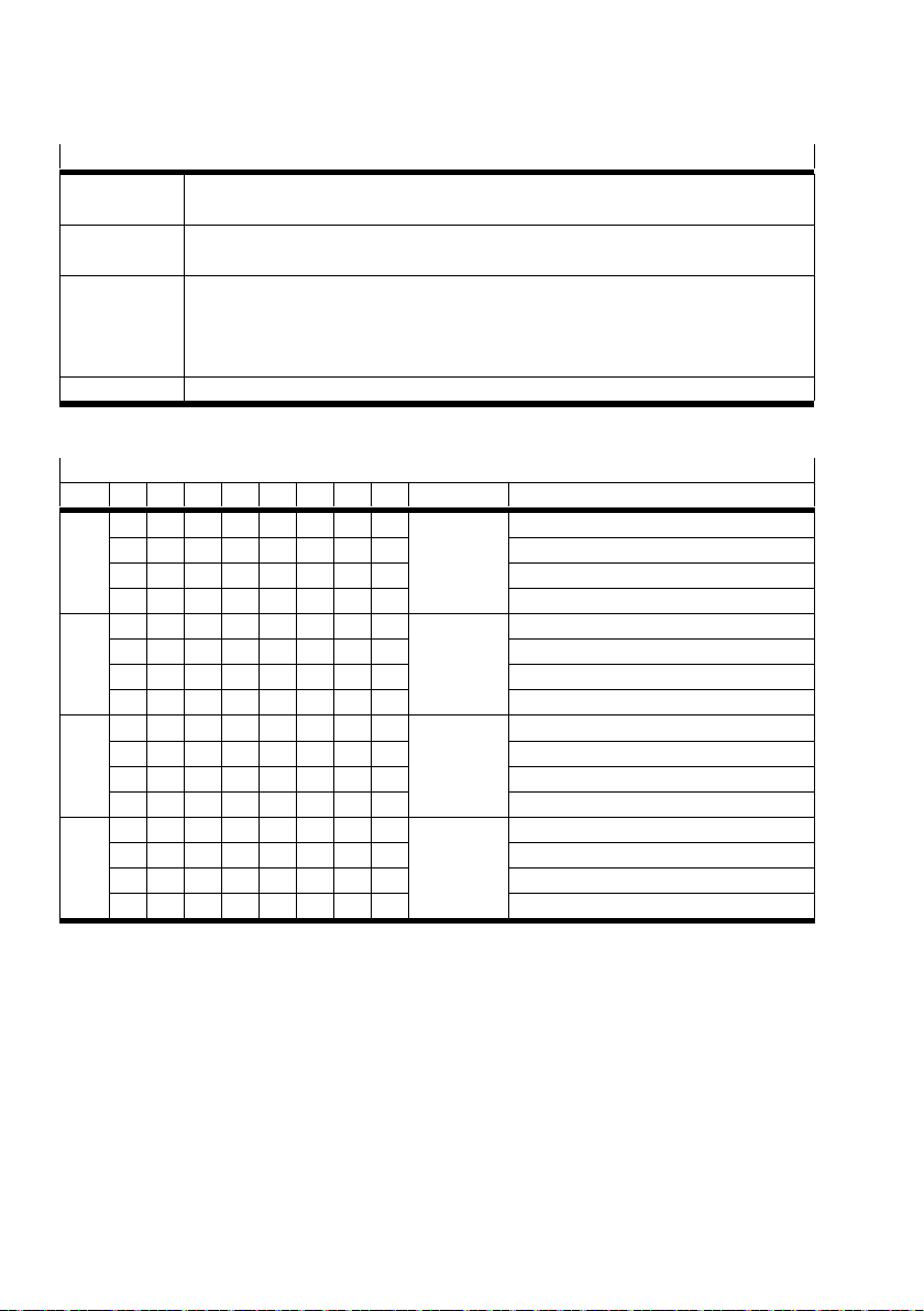
Channel parameter: signal range of channel 0 … 3
Function
4828 + m* 64 + 30 m = module number (0 … 47)
number
Description Setting of the signal range of the inputs and outputs for the individual channels of
the analogue input module è Chap. 8.5.
Allocation Bit 0 … 1: Signal range of channel 0
Bit 2 … 3: Signal range of channel 1
Bit 4 … 5: Signal range of channel 2
Bit 6 … 7: Signal range of channel 3
Values è Tab. 25.
Tab. 24 Description of “Signal range of channel 0 … 3” channel parameter
Allocation and values 4828 + m* 64 + 30 (m = module number)
Bit 7 6 5 4 3 2 1 0 Channel Signal range
x x x x x x 0 0 Channel 0 Inactive
x x x x x x 0 1 4 … 20 mA without HART
x x x x x x 1 0 4 … 20 mA with HART
x x x x x x 1 1 0 … 20 mA
x x x x 0 0 x x Channel 1 Inactive
x x x x 0 1 x x 4 … 20 mA without HART
x x x x 1 0 x x 4 … 20 mA with HART
x x x x 1 1 x x 0 … 20 mA
x x 0 0 x x x x Channel 2 Inactive
x x 0 1 x x x x 4 … 20 mA without HART
x x 1 0 x x x x 4 … 20 mA with HART
x x 1 1 x x x x 0 … 20 mA
0 0 x x x x x x Channel 3 Inactive
0 1 x x x x x x 4 … 20 mA without HART
1 0 x x x x x x 4 … 20 mA with HART
1 1 x x x x x x 0 … 20 mA
Tab. 25 Allocation and values of the “Signal range” channel parameter
40 Festo – CPX-4AE-4AA-H – 2017-12 English
Page 41
CPX-4AE-4AA-H
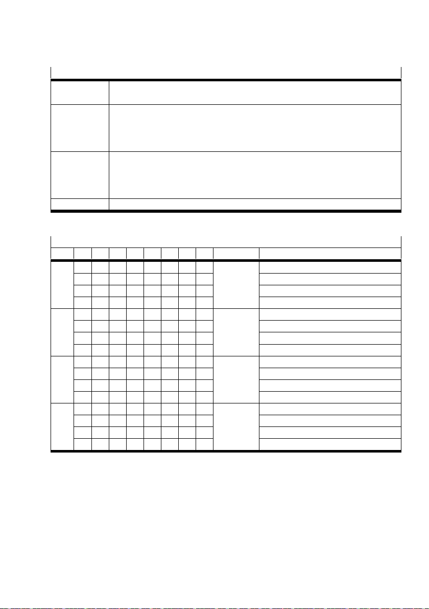
Channel parameter: smoothing factor of channel 0 … 3
Function
4828 + m* 64 + 31 m = module number (0 … 47)
number
Description Setting of the smoothing factor for the individual channels of the analogue input
module:
– With the smoothing factor, malfunctions can be suppressed.
– Calculation of the smoothing factor: arithmetic mean value from n values
Allocation Bit 0 … 1: Smoothing factor of channel 0
Bit 2 … 3: Smoothing factor of channel 1
Bit 4 … 5: Smoothing factor of channel 2
Bit 6 … 7: Smoothing factor of channel 3
Values è Tab. 27.
Tab. 26 Description of the “Smoothing factor of channel 0 … 3” channel parameter
Allocation and values 4828 + m* 64 + 31 (m = module number)
Bit 7 6 5 4 3 2 1 0 Channel Smoothing factor
x x x x x x 0 0 Channel 0 Inactive
x x x x x x 0 1 Smoothing over 2 values
x x x x x x 1 0 Smoothed over 4 values
x x x x x x 1 1 Smoothing over 8 values
x x x x 0 0 x x Channel 1 Inactive
x x x x 0 1 x x Smoothing over 2 values
x x x x 1 0 x x Smoothed over 4 values
x x x x 1 1 x x Smoothing over 8 values
x x 0 0 x x x x Channel 2 Inactive
x x 0 1 x x x x Smoothing over 2 values
x x 1 0 x x x x Smoothed over 4 values
x x 1 1 x x x x Smoothing over 8 values
0 0 x x x x x x Channel 3 Inactive
0 1 x x x x x x Smoothing over 2 values
1 0 x x x x x x Smoothing over 4 values
1 1 x x x x x x Smoothing over 8 values
Tab. 27 Allocation and values of the “Smoothing factor” channel parameter
Festo – CPX-4AE-4AA-H – 2017-12 English 41
Page 42
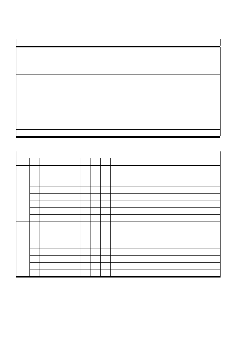
CPX-4AE-4AA-H
Channel parameter: IEEE variable of channel 0 … 3
Function
number
4828 + m* 64 + 32
(HART variable 1, HART variable 2)
m = module number (0 … 47)
4828 + m* 64 + 33
(HART variable 3, HART variable 4)
Description For each HART variable in the process image, the channel and source can be
determined:
– HART variables can be set individually for each channel.
– To use the HART variables: set the DIL switch è Chap. 7.3.
Allocation Bit 0, 1 Source of HART variable 1 or HART variable 3
Bit 2, 3 Channel of HART variable 1 or HART variable 3
Bit 4, 5 Source of HART variable 2 or HART variable 4
Bit 6, 7 Channel of HART variable 2 or HART variable 4
Values è Tab. 29, Tab. 30.
Tab. 28 Description of “IEEE variable of channel 0 … 3” channel parameter
Allocation and values 4828 + m* 64 + 32 (m = module number)
Bit 7 6 5 4 3 2 1 0 HART variable 1, HART variable 2
x x x x x x 0 0 Source of HART variable 1 = PV (presetting)
x x x x x x 0 1 Source of HART variable 1 = SV
x x x x x x 1 0 Source of HART variable 1 = TV
x x x x x x 1 1 Source of HART variable 1 = QV
x x x x 0 0 x x Channel of HART variable 1 = channel 0 (presetting)
x x x x 0 1 x x Channel of HART variable 1 = channel 1
x x x x 1 0 x x Channel of HART variable 1 = channel 2
x x x x 1 1 x x Channel of HART variable 1 = channel 3
x x 0 0 x x x x Source of HART variable 2 = PV (presetting)
x x 0 1 x x x x Source of HART variable 2 = SV
x x 1 0 x x x x Source of HART variable 2 = TV
x x 1 1 x x x x Source of HART variable 2 = QV
0 0 x x x x x x Channel of HART variable 2 = channel 0 (presetting)
0 1 x x x x x x Channel of HART variable 2 = channel 1
1 0 x x x x x x Channel of HART variable 2 = channel 2
1 1 x x x x x x Channel of HART variable 2 = channel 3
Tab. 29 Allocation and values of “IEEE variable of HART variable 1, HART variable 2” channel
parameter
42 Festo – CPX-4AE-4AA-H – 2017-12 English
Page 43
CPX-4AE-4AA-H
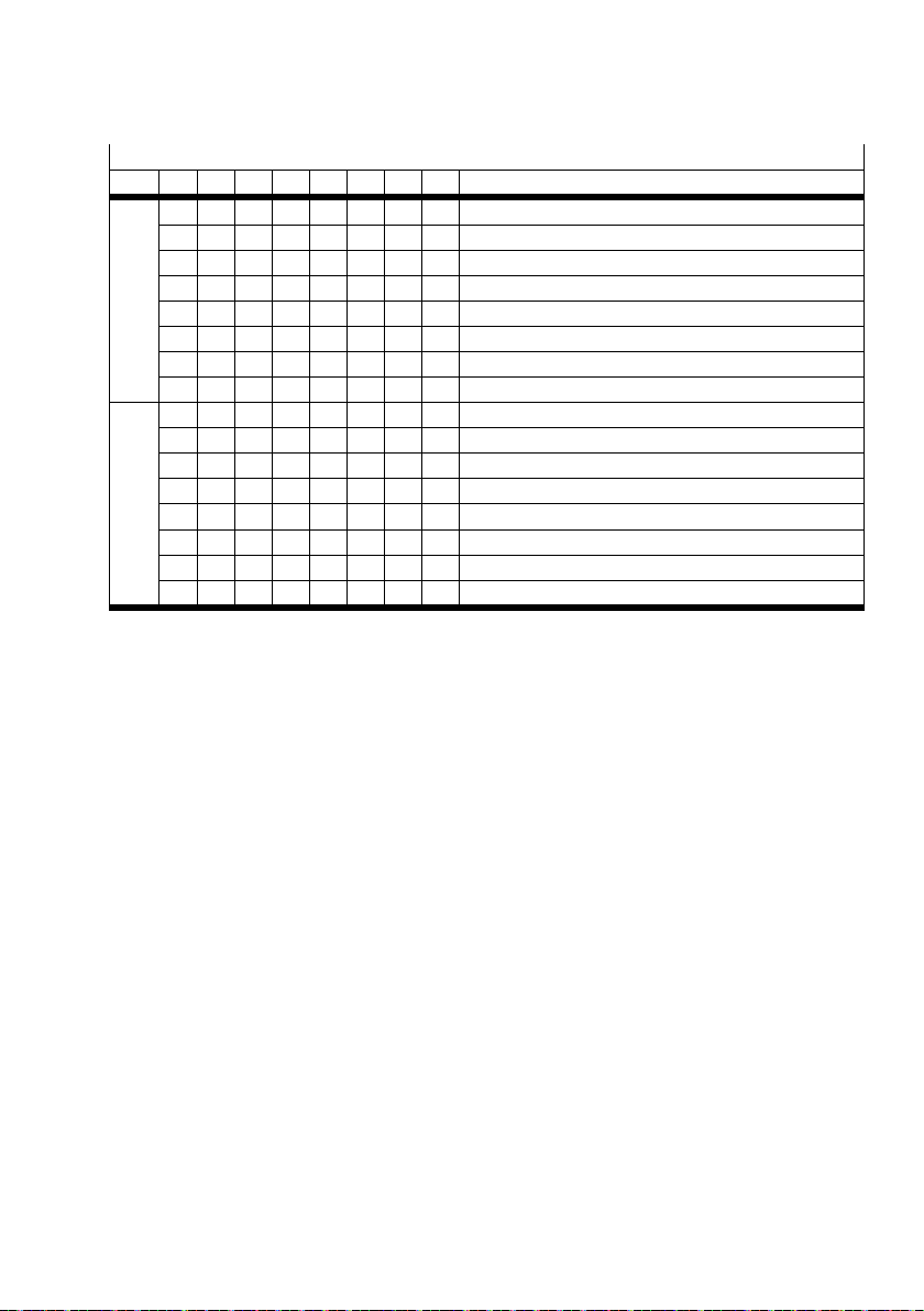
Allocation and values 4828 + m* 64 + 33 (m = module number)
Bit 7 6 5 4 3 2 1 0 HART variable 3, HART variable 4
x x x x x x 0 0 Source of HART variable 3 = PV (presetting)
x x x x x x 0 1 Source of HART variable 3 = SV
x x x x x x 1 0 Source of HART variable 3 = TV
x x x x x x 1 1 Source of HART variable 3 = QV
x x x x 0 0 x x Channel of HART variable 3 = channel 0 (presetting)
x x x x 0 1 x x Channel of HART variable 3 = channel 1
x x x x 1 0 x x Channel of HART variable 3 = channel 2
x x x x 1 1 x x Channel of HART variable 3 = channel 3
x x 0 0 x x x x Source of HART variable 4 = PV (presetting)
x x 0 1 x x x x Source of HART variable 4 = SV
x x 1 0 x x x x Source of HART variable 4 = TV
x x 1 1 x x x x Source of HART variable 4 = QV
0 0 x x x x x x Channel of HART variable 4 = channel 0 (presetting)
0 1 x x x x x x Channel of HART variable 4 = channel 1
1 0 x x x x x x Channel of HART variable 4 = channel 2
1 1 x x x x x x Channel of HART variable 4 = channel 3
Tab. 30 Allocation and values of “IEEE variable of HART variable 3, HART variable 4” channel
parameter
Festo – CPX-4AE-4AA-H – 2017-12 English 43
Page 44

CPX-4AE-4AA-H
Module parameter: Fail-Safe channel 0 … 3
Function
number
Access to this module parameter is made via protocol-specific functions
è Description for the bus node.
Description Channel-specific determination as to which signal status the outputs have during
fieldbus communication errors.
Fail-Safe can be defined for the entire terminal CPX via the “Fail-Safe” system
parameter è Description of system CPX.
Parameterisation of “Fault-Mode of channel x”
Depending on the fieldbus protocol, “Fault-Mode” is parameterised as follows:
– By setting a parameter bit (e.g., for CPX-FB11)
– By setting all parameter bits of the pertinent work to “Hold Last State” or
“Fault State” (e.g. for CPX-FB13)
Parameterisation of “Fault State of channel x”
The desired output word must be mapped in the “Fault State” parameter bits of the
respective channel.
Values Fault-Mode of channel 0 … 3:
0 = Hold Last State
1 = Fault State (presetting)
Fault State of channel 0 … 3:
0 = Reset value (presetting)
1 = Set value
Tab. 31 Description of “Fail-Safe of channel 0 … 3” module parameter
Module parameter: Idle-Mode channel 0 … 3
Function
number
Access to this module parameter is made via protocol-specific functions
è Description for the bus node.
Description Channel-specific determination as to which signal status the outputs have during
the call of the idle function.
Idle-Mode can be defined for the entire terminal CPX via the “System Idle-Mode”
system parameter è Description of system CPX.
Parameterisation of “Idle-Mode of channel x”
“Idle-Mode” is parameterised by setting a parameter bit.
Parameterisation of “Idle State of channel x”
The desired output word must be mapped in the “Idle State” parameter bits of the
respective channel.
Values Idle-Mode of channel 0 … 3:
0 = Hold Last State
1 = Fault State (presetting)
Idle State of channel 0 … 3:
0 = Reset value (presetting)
1 = Set value
Tab. 32 Description of “Idle-Mode of channel 0 … 3” module parameter
44 Festo – CPX-4AE-4AA-H – 2017-12 English
Page 45

CPX-4AE-4AA-H
Module parameter: forcing of channel 0 … 3
Function
number
Access to this module parameter is made via protocol-specific functions
è Description for the bus node.
Description With the forcing function, the digital input and output values can be influenced
independently of the actually pending input and output signal.
Forcing can be defined for the entire terminal CPX via the “Force Mode” system
parameter è Description of system CPX.
Parameterisation of “Force-Mode of channel x”
Depending on the fieldbus protocol, “Force-Mode” is parameterised as follows:
– By setting a parameter bit (e.g., for CPX-FB11)
– By setting all parameter bits of the pertinent word to “blocked” or “Force State”
(e.g. for CPX-FB13)
Parameterisation of “Force State of channel x”
The desired output word must be mapped in the “Force State” parameter bits of the
respective channel.
Values Force-Mode of channel 0 … 3:
0 = Disabled (presetting)
1 = Force State
Force State of channel 0 … 3:
0 = Reset value (presetting)
1 = Set value
Tab. 33 Description of the “Forcing of channel 0 … 3” module parameter
Festo – CPX-4AE-4AA-H – 2017-12 English 45
Page 46
CPX-4AE-4AA-H
8.5 Data format and range of values of the actual values
8.5.1 Data format
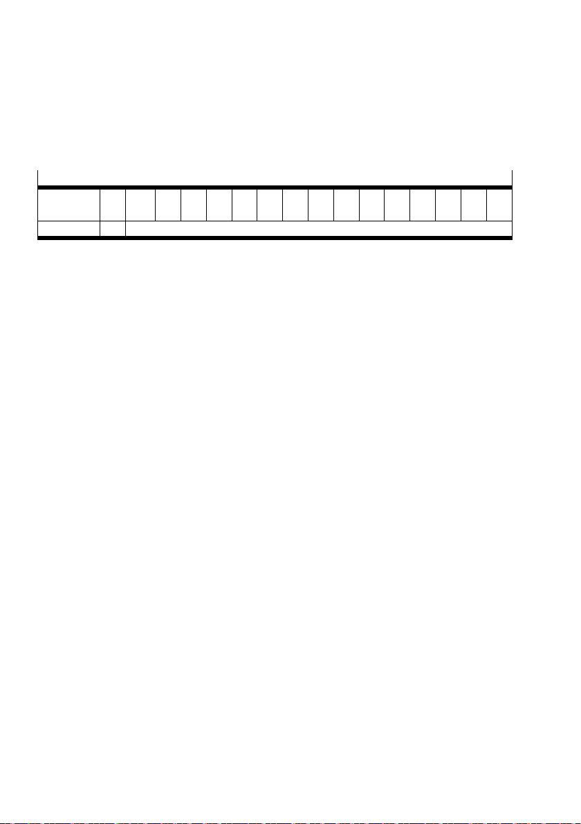
The data format determines how the actual values (analogue values) are transferred by terminal CPX to
the control system.
Data format
Input data
field
Value VZ1)Digital input value
1) VZ = sign (0 = positive, 1 = negative)
Tab. 34 Data format of the module CPX-4AE-4AA-H
– Range of values -32768 … 0 … 32767
D15 D14
MSB
D13 D12 D11 D10 D9 D8 D7 D6 D5 D4 D3 D2 D1 D0
LSB
46 Festo – CPX-4AE-4AA-H – 2017-12 English
Page 47
CPX-4AE-4AA-H
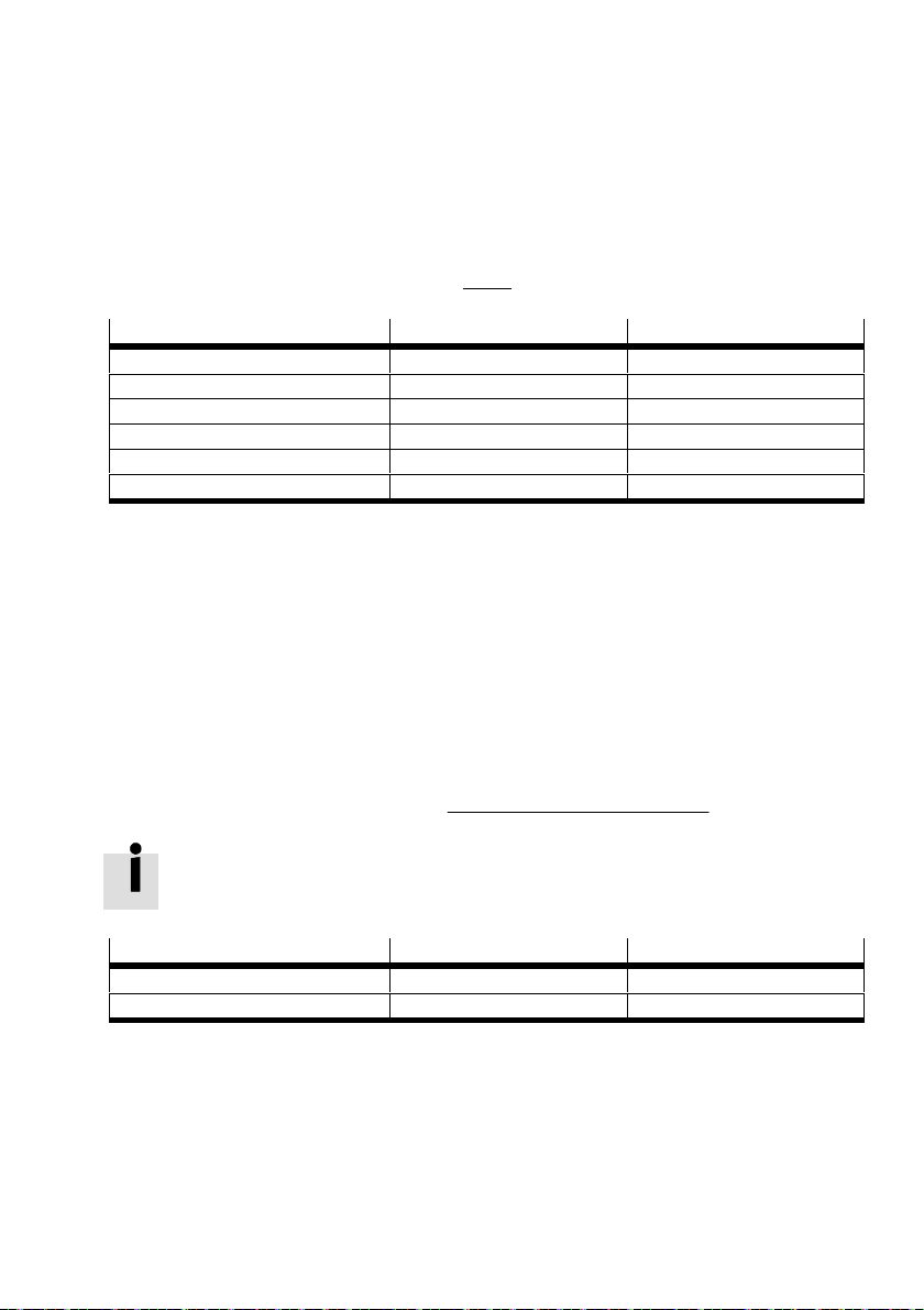
8.5.2 Input 4 … 20 mA - fixed data format
– Measuring range 4 … 20 mA
– Data format: sign + 15 bits
– Data format not scalable
– Conversion of analogue actual value to the digital input value:
Digital input value + (Actual value * 4)
27648
16
Actual value Digital input value Significance
> 22.81 mA 32767 Overflow
22.81 mA 32511 End of the measuring range
> 20 mA 27649 … 32511 Overdrive range
4 … 20 mA 0 … 27648 Nominal range
< 4 mA -1 … -4864 Underdrive range
1.19 mA -4864 End of the measuring range
Tab. 35 Range of values for fixed data format (input 4 … 20 mA)
8.5.3 Input 4 … 20 mA – scalable data format
– Measuring range 4 … 20 mA
– Scalable data format -32768 … 0 … 32767
– Scaling above the lower and upper limit value
– Use of the limit values for diagnostics
– Conversion of the current values 1.19 … 22.81 mA (for sufficiently scaled data range)
– Overflow or underflow for values outside of the data range for actual values (> 22.81 mA
or < 1.19 mA) or digital input value (> 32767 or < -32768)
– Conversion of analogue actual value to the digital input value:
Digital input value + (Actual value * 4)
Upper limit value * Lower limit value
16
) Lower limit value
To perform complete diagnostics: do not scale the measuring range above the complete
data range.
Actual value Digital input value Significance
4 … 20 mA -32768 … 32767 Nominal range, freely scalable
< 1.19 mA -32768 Underflow
Tab. 36 Range of values for scalable data format (input 4 … 20 mA)
Festo – CPX-4AE-4AA-H – 2017-12 English 47
Page 48
CPX-4AE-4AA-H
8.5.4 Input 0 … 20 mA – fixed data format
– Measuring range 0 … 20 mA
– Data format not scalable
– No underflow: actual values < 0 mA not possible (reverse polarity protection)
– Conversion of analogue actual value to the digital input value:
Digital input value + Actual value
27648
20
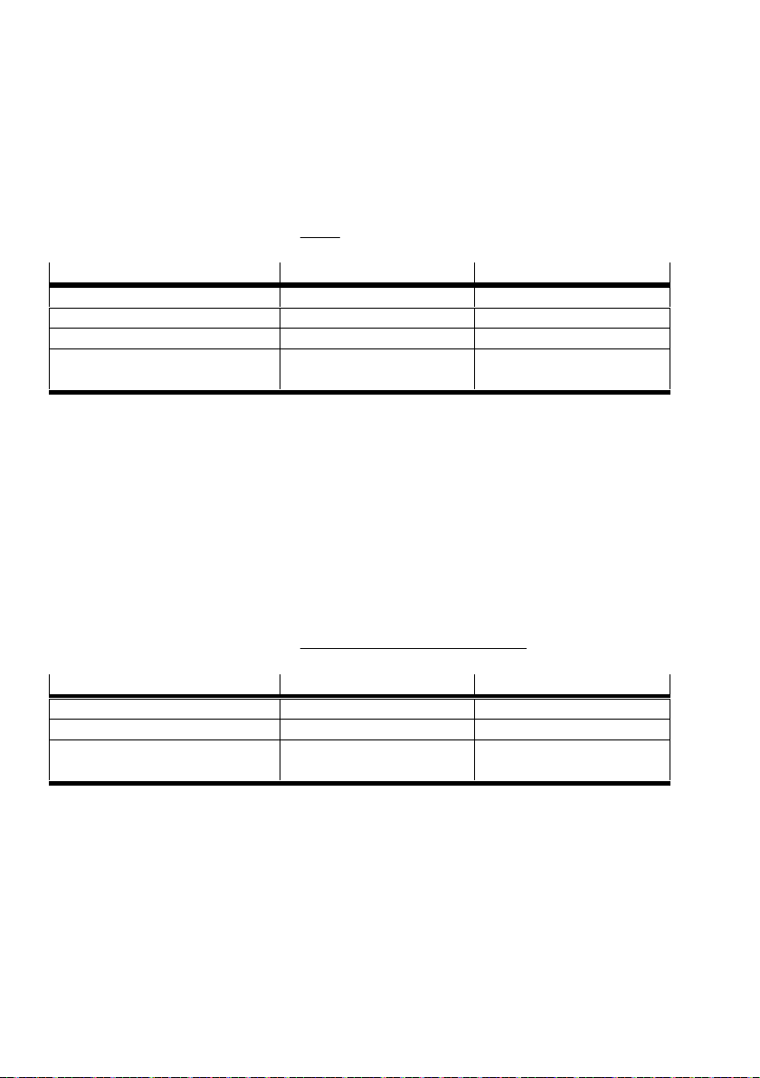
Actual value Digital input value Significance
23.52 mA 32511 End of the measuring range
> 20 mA 27649 … 32511 Overdrive range
0…20 mA 0 … 27648 Nominal range
< 0 mA – Underflow not possible:
reverse polarity protection
Tab. 37 Range of values for fixed data format (input 0 … 20 mA)
8.5.5 Input 0 … 20 mA – scalable data format
– Measuring range 0 … 20 mA
– Scalable data format -32768 … 0 … 32767
– Scaling above the lower and upper limit value
– Use of the limit values for diagnostics
– Conversion of the current values 0 … 23.52 mA (for sufficiently scaled data range)
– Overflow or underflow for values outside of the data range (> 32767 or < -32768)
– No underflow: actual values < 0 mA not possible (reverse polarity protection)
– Conversion of analogue actual value to the digital input value:
Digital input value + Actual value
Upper limit value * Lower limit value
20
) Lower limit value
Actual value Digital input value Significance
> 23.52 mA (hysteresis < 23.42 mA) 32767 Overflow
0 … 20 mA -32768 … 32767 Nominal range, freely scalable
< 0 mA < -32768 Underflow not possible:
reverse polarity protection
Tab. 38 Range of values for scalable data format (input 0 … 20 mA)
48 Festo – CPX-4AE-4AA-H – 2017-12 English
Page 49
CPX-4AE-4AA-H
8.5.6 Output 4 … 20 mA – fixed data format
– Range of values 4 … 20 mA
– Data format not scalable
– Current value output 0 … 22 mA
– Current value output in case of overflow (> 22 mA): 22 mA
– Current value output in case of underflow (< 0 mA): 0 mA
– Conversion of the digital output value to the analogue setpoint value (current value output)
Current value + 4 ) 16
Digital output value
27648
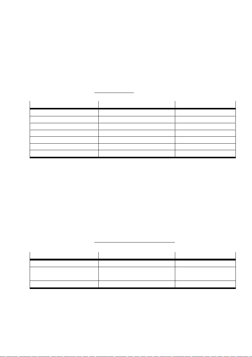
Digital output value Current value output Significance
> 31104 22 mA Overflow
31104 22 mA End of output range
27649 … 31104 > 20 mA Overdrive range
0 … 27648 4 … 20 mA Nominal range
-1 … -6912 < 4 mA Underdrive range
-6912 0 mA End of output range
< -6912 0 mA Underflow
Tab. 39 Range of values in case of fixed data format (output 4 … 20 mA)
8.5.7 Output 4 … 20 mA – scalable data format
– Range of values -32768 … 0 … 32767
– Scalable data format -32768 … 0 … 32767
– Scaling above the lower and upper limit value
– Use of the limit values for diagnostics
– Current value output 0 … 22 mA (for sufficiently scaled data range)
– Current value output in case of overflow (> 22 mA): 22 mA
– Current value output in case of underflow (< 0 mA): 0 mA
– Conversion of the digital output value to the analogue setpoint value (current value output)
Current value + 4 ) 16
Digital output value * Lower limit value
Upper limit value * Lower limit value
Digital output value Current value output Significance
> 32767 22 mA Overflow
-32768 … 0 … 32767 4 … 20 mA Nominal range, freely
scalable
< -32768 0 mA Underflow
Tab. 40 Range of value for scalable data format (output 4 … 20 mA)
Festo – CPX-4AE-4AA-H – 2017-12 English 49
Page 50
CPX-4AE-4AA-H
8.5.8 Output 0 … 20 mA – fixed data format
– Range of values 0 … 20 mA
– Data format not scalable
– Current value output in case of overflow (> 22 mA): 22 mA
– Current value output in case of underflow (< 0 mA): 0 mA
– Conversion of the digital output value to the analogue setpoint value (current value output)
Current value + 20
Digital output value
27648
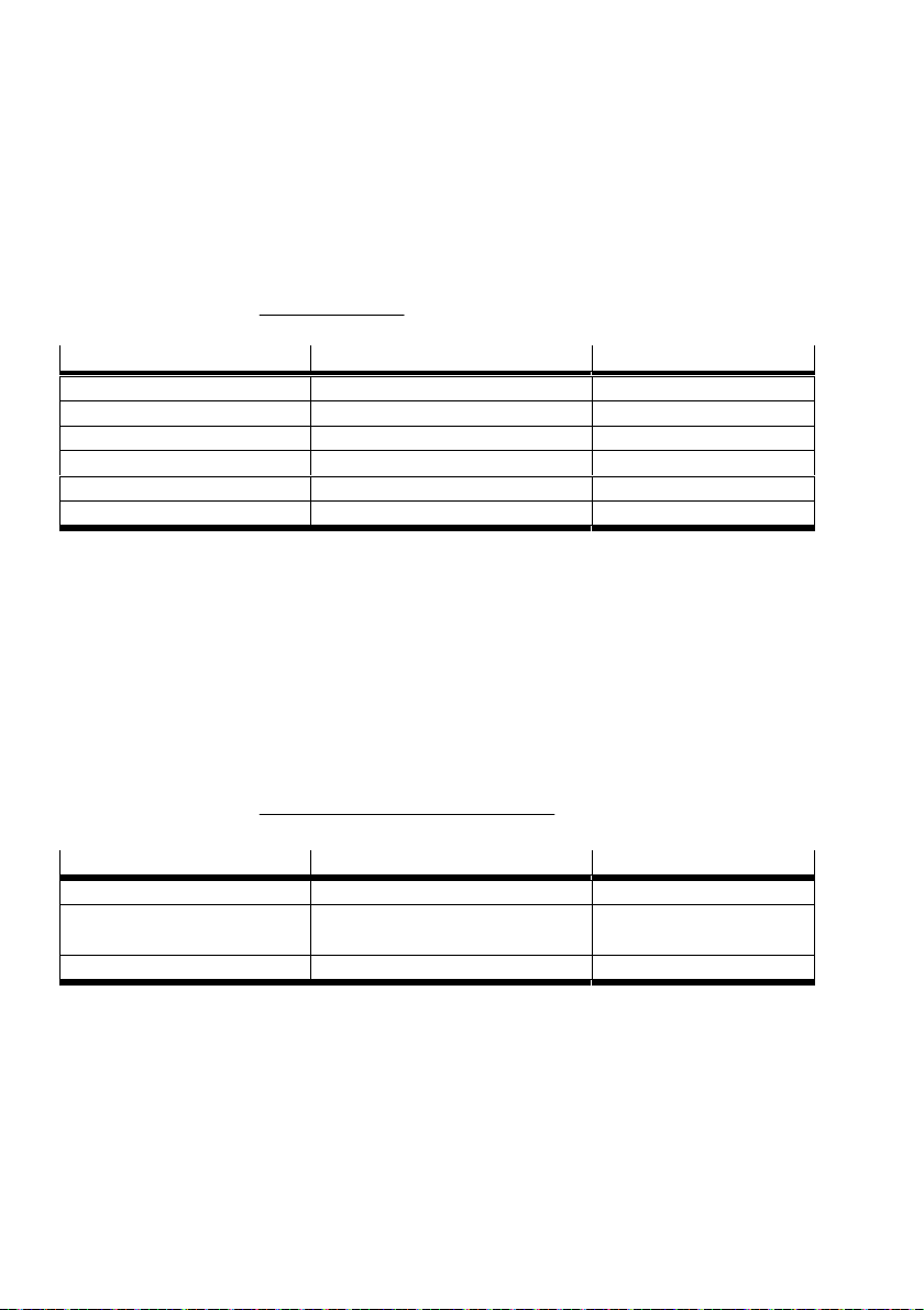
Digital output value Current value output Significance
> 30413 22 mA Overflow
30413 22 mA End of output range
27649 … 30413 > 20 mA Overdrive range
0 … 27648 0 … 20 mA Nominal range
0 0 mA End of output range
< 0 0 mA Underflow
Tab. 41 Range of values in case of fixed data format (output 0 … 20 mA)
8.5.9 Output 0 … 20 mA – scalable data format
– Range of values 0 … 20 mA
– Data format scalable from -32768 … 0 … 32767
– Scaling above the lower and upper limit value
– Use of the limit values for diagnostics
– Current value output in case of overflow (> 22 mA): 22 mA
– Current value output in case of underflow (< 0 mA): 0 mA
– Conversion of the digital output value to the analogue setpoint value (current value output)
Current value + 20
Digital output value * Lower limit value
Upper limit value * Lower limit value
Digital output value Current value output Significance
> 32767 22 mA Overflow
-32768 … 0 … 32767 0 … 20 mA Nominal range,
freelyscalable
< -32768 0 mA Underflow
Tab. 42 Range of values for scalable data format (output 0 … 20 mA)
50 Festo – CPX-4AE-4AA-H – 2017-12 English
Page 51
CPX-4AE-4AA-H
8.6 Scaling the range of values
For the scalable data format, the range of values can be scaled by setting the limit values. To process
the diagnostics correctly, the distance between both limit values should amount to at least 100
1. Set the “linear scaling” data format è Tab. 18.
2. Set the limit values for each channel è Tab. 20, Tab. 21.
The limit values represent the scaling end values:
– When the upper limit value is positive, set the upper limit value before setting the lower limit
value.
– If the upper limit value is negative, set the lower limit value before setting the upper limit value.
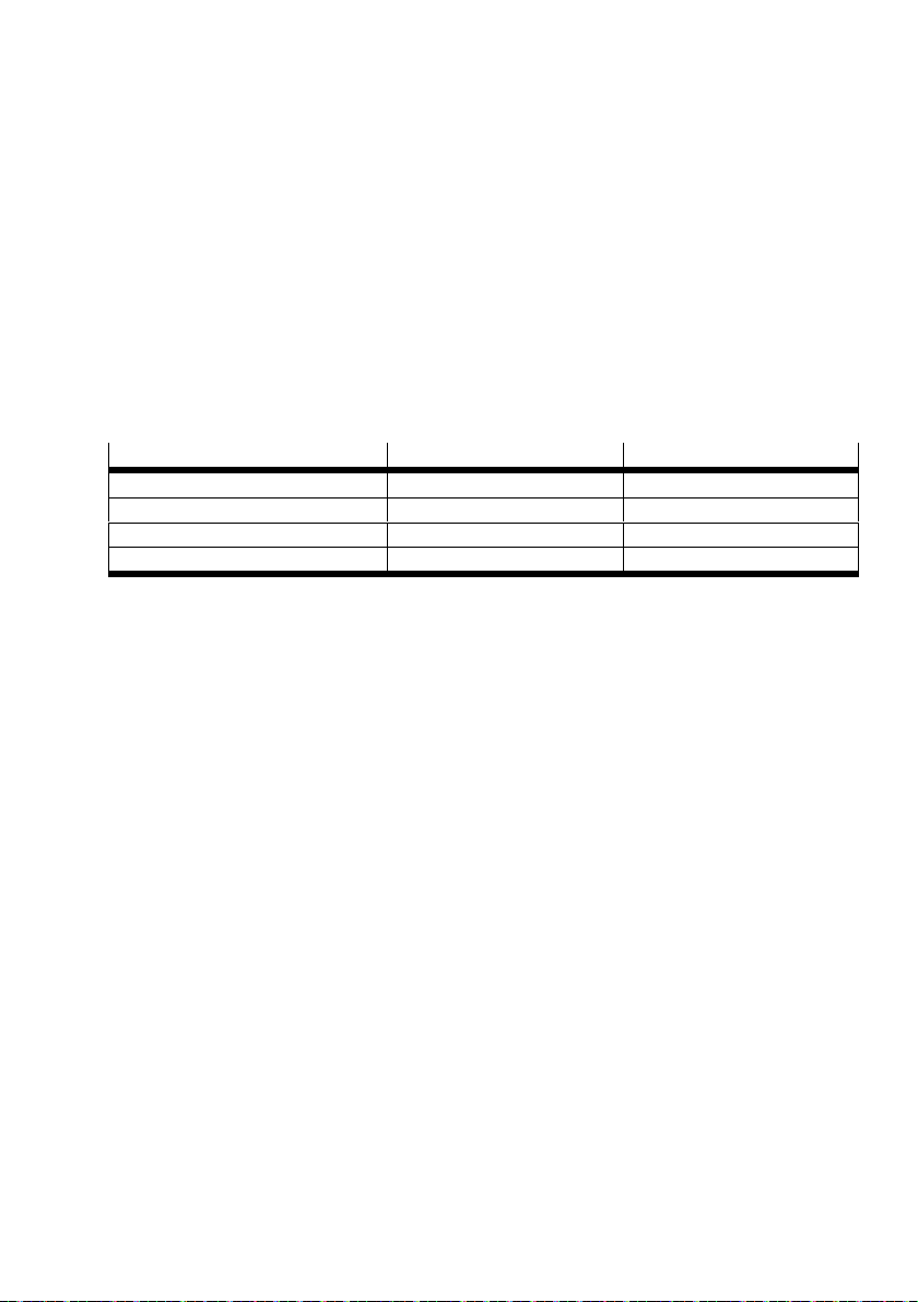
Example: scaling appropriate for a pressure sensor
The sensor linearly converts the measuring range 0 … 6 bar to analogue current values 0 … 20 mA.
Actual value (example) Digital input value Significance
0 mA 0 Lower limit value
10 mA 3000 Value in nominal range
20 mA 6000 Upper limit value
22 mA 6600 Limit value exceeded
Tab. 43 Example of scaling and limit monitoring for a pressure sensor
dec
.
Festo – CPX-4AE-4AA-H – 2017-12 English 51
Page 52

CPX-4AE-4AA-H
9 Diagnostics
9.1 General remarks
Specific errors of the analogue module are reported or suppressed dependent on the module
parameterisation è Tab. 16.
The monitoring of the errors can be activated or deactivated independently of each other.
Active monitoring has the following effect:
è The error is sent to the CPX bus node.
è The module error LED and channel error LED light up.
The representation of errors in the bus nodes depends on the bus protocol è Description
of bus nodes.
A further possibility for diagnostics is the operator unit CPX-MMI. The operator unit
displays the error messages in clear text è Description of operator unit CPX-MMI.
52 Festo – CPX-4AE-4AA-H – 2017-12 English
Page 53
CPX-4AE-4AA-H
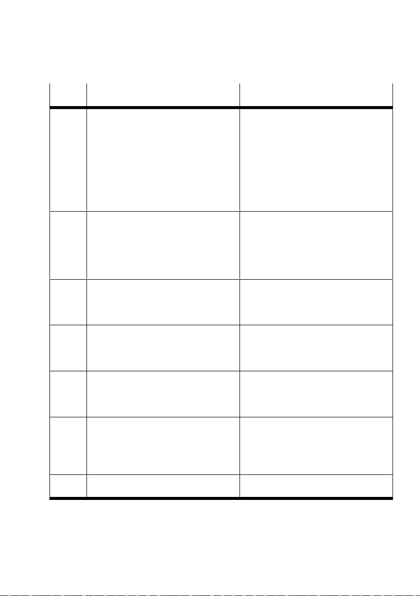
9.2 Error messages
Error
Error description Error elimination
number
2 Short circuit or overload at the input or
1)
output
– The behaviour in case of short
circuit/overload and the error
1. Check the cables and connected
devices. Replace defective cables and
devices.
2. Switch voltage on again.
elimination measures depend on the
parameterisation of the “Behaviour
after short circuit/overload” module
parameter.
– Parameter description è Tab. 17.
3 Wire break (idling) of current input or
current output
1)
– Only for signal range 4 … 20 mA
Check the cables and connected
devices. Replace defective cables and
devices.
– Input: IIN < 1.2 mA
– Output: no signal is present.
– Parameter description è Tab. 19.
9 Lower limit value undershot
– The parameterised lower limit value has
1)
Check analogue input.
Check parameterised limit value.
been undershot.
– Parameter description è Tab. 19.
10 Upper limit value exceeded
– The parameterised upper limit value has
1)
Check analogue input.
Check parameterised limit value.
been exceeded.
– Parameter description è Tab. 19.
29 Error in parameterisation
– Parameterisation is implausible.
1)
Reparameterise with valid
parameters è Chap. 8.5.
– The previous parameter setting of the
channel is kept.
60 Overflow/underflow
– The actual value or setpoint value lies
outside of the measuring range or
displayable range of values.
2)
Check analogue input.
Check the cables and connected
devices. Replace defective cables
anddevices.
– Parameter description è Tab. 19.
100 Configuration error
– The DIL switch is incorrectly set.
1) The module displays the error depending on the parameterisation. The digital input values are processed again.
2) The diagnostics are output with the first recorded input value and kept until valid input values have been recorded for at least
200 ms.
Correct the setting of the DIL switch
è Chap. 7.3.
Festo – CPX-4AE-4AA-H – 2017-12 English 53
Page 54
CPX-4AE-4AA-H
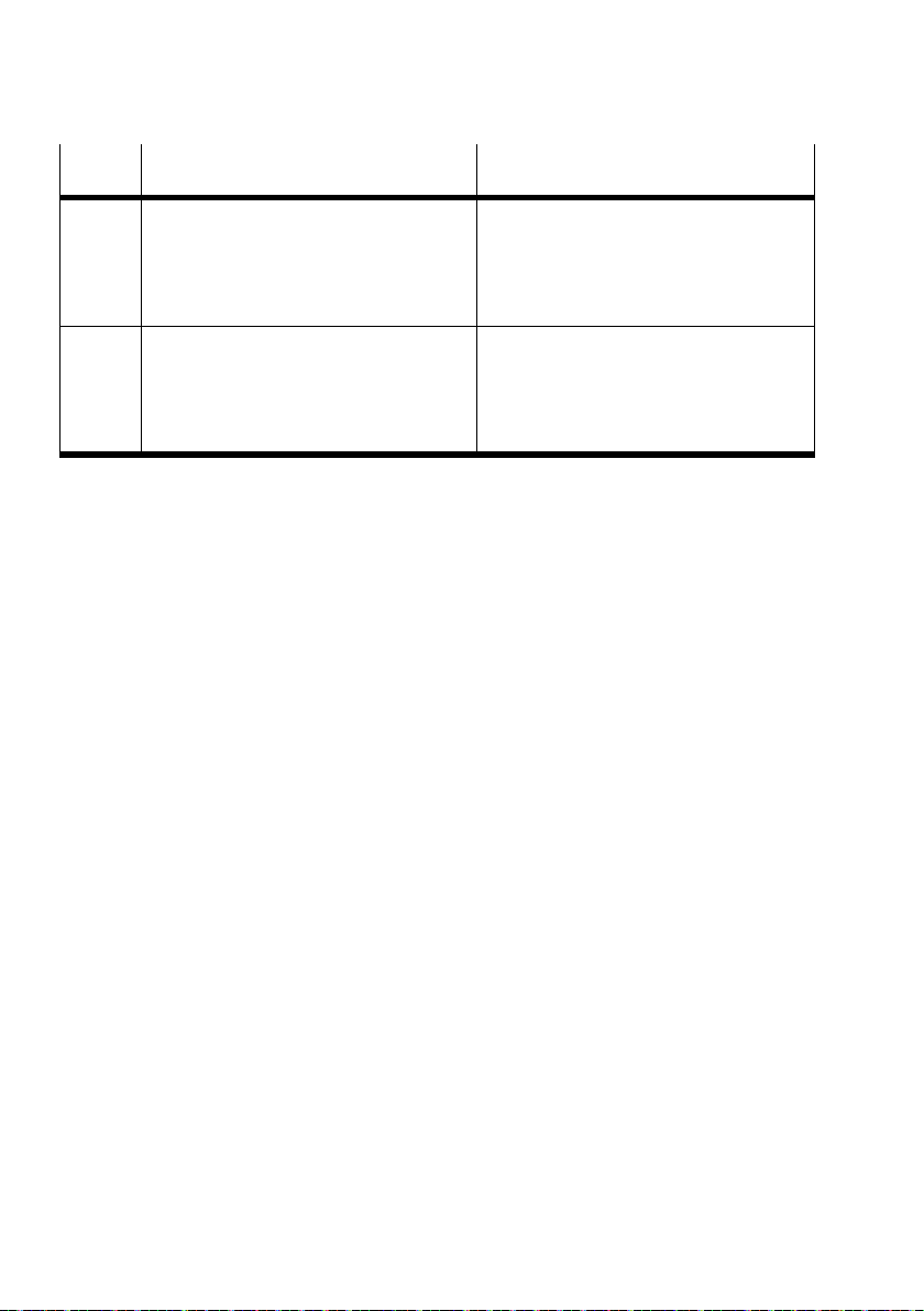
Error
Error eliminationError description
number
121 Limit value according to NAMUR NE43
exceeded
Check analogue input.
Reparameterise with valid parameters.
– Only for signal range 4 … 20 mA
– Input: IIN 21.00 mA
– Parameter description è Tab. 18.
122 Limit value according to NAMUR NE43
undershot
Check analogue input.
Reparameterise with valid parameters.
– Only for signal range 4 … 20 mA
– Input: IIN 3.6 mA
– Parameter description è Tab. 18.
1) The module displays the error depending on the parameterisation. The digital input values are processed again.
2) The diagnostics are output with the first recorded input value and kept until valid input values have been recorded for at least
200 ms.
Tab. 44 Error messages of the analogue module
54 Festo – CPX-4AE-4AA-H – 2017-12 English
Page 55
CPX-4AE-4AA-H
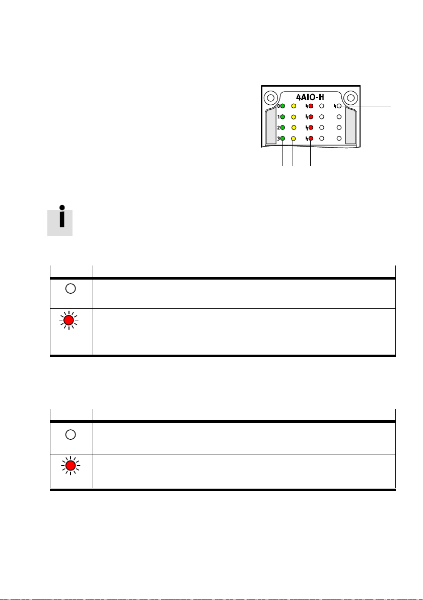
9.3 LED indicator
1 Module error indicator (red LED) è Tab. 45.
2 Channel error indicator (red LED) è Tab. 46.
3 Channel status indicator of input è Tab. 47.
4 Channel status indicator of output è Tab. 48.
Fig. 18 LED indicator of analogue module
The display of errors can be suppressed during parameterisation è Tab. 16, Tab. 19.
Module error indicator
LED (red) Description
Error-free operation
Off
Module error
– All channel-specific errors
Lights up
Tab. 45 Indicator: module error LED
– Parameterisation errors of hysteresis è Tab. 17.
– The DIL switch is incorrectly set.
1
234
Channel error indicator
Each channel is assigned an LED.
LED (red) Description
Error-free operation
Off
Channel-specific errors è Tab. 44.
Lights up
Tab. 46 Indicator: channel error LED
Festo – CPX-4AE-4AA-H – 2017-12 English 55
Page 56
CPX-4AE-4AA-H
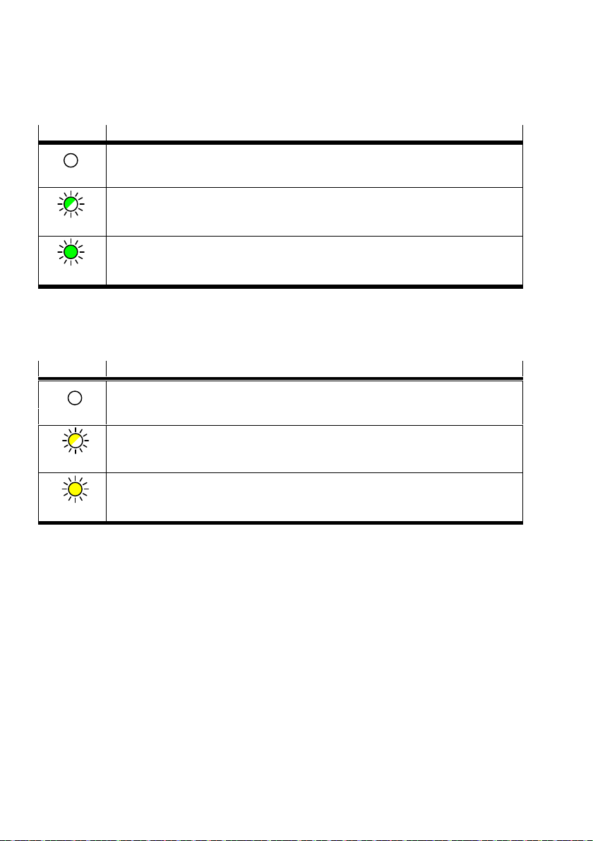
Channel status indicator of input
The LEDs 0 … 3 (green) indicate the status of the individual channels.
LED (green)
Description
Channel inactive or active as output
Off
Channel active as input:
– Signal range 4 … 20 mA with HART
Flashes
– HART communication error-free
Channel active as input
Lights up
Tab. 47 Indicator: status LED for channel status of input
Channel status indicator of output
The LEDs 0 … 3 (yellow) indicate the status of the individual channels.
LED (yellow) Description
Channel inactive or active as input
Off
Channel active as output:
– Signal range 4 … 20 mA with HART
Flashes
– HART communication error-free
Channel active as output
Lights up
Tab. 48 Indicator: status LED for channel status of output
56 Festo – CPX-4AE-4AA-H – 2017-12 English
Page 57
CPX-4AE-4AA-H
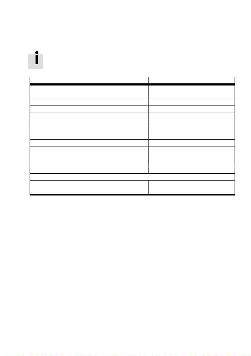
10 Technical data
Technical data of terminal CPX è Description of system CPX.
Feature
Dimensions (Length x Width x Height) [mm] 107 x 50 x 70, including interlinking block
Product weight, including interlinking [g] 78
Type of mounting On interlinking block
Ambient temperature [°C] -5…50
Storage temperature [°C] -20…70
Air humidity (non-condensing) [%] 95
Degree of protection to EN 60529 Depending on connection block
Electromagnetic compatibility To EN 61000-6-2/-4
CE marking
(Declaration of conformity è www.festo.com/sp)
Note on materials RoHS compliant
Information on materials
– Housing PA reinforced
Tab. 49 General technical data
Specification/value
and connection block
In accordance with EU explosion
protection guideline (ATEX)
In accordance with EU EMC Directive
PC
Festo – CPX-4AE-4AA-H – 2017-12 English 57
Page 58
CPX-4AE-4AA-H
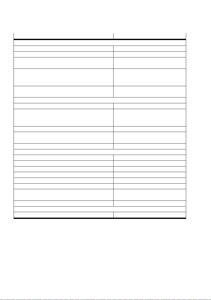
Feature Specification/value
Power supply
Nominal operating voltage [V DC] 24
Operating voltage range [V DC] 18 … 30
Intrinsic current consumption at nominal
[mA] Typically 170, max. 200
operating voltage
Electrical connection – M12 4-pin
– Spring-loaded terminal
– Screw terminal
Reverse polarity protection – For operating voltage
– Per channel for inputs and outputs
Analogue current channels
Quantity 4, selectable as inputs or outputs
Signal range [mA] – 0 … 20 without HART
– 4 … 20 without HART
– 4 … 20 with HART
Repetition accuracy at 25°C [%] 0.05
Operating error limit related to the ambient
[%] ± 0.3
temperature range
Basic error limit at 25°C [%] ± 0.1
Analogue inputs
Input resistance [Ω] 300
Open circuit voltage [V DC] Max. 28.8
Short circuit current [mA] Max. 22
Available sensor voltage [V] Min. 20.7 at 20 mA
Sensor cable length [m] Max. 500 (screened)
Electrical isolation between channels None
Electrical isolation between channel
Yes
and internal bus
Fuse protection (short circuit) Per channel
Analogue outputs
Load resistance [Ω] Max. 750
Tab. 50 Electrical data
58 Festo – CPX-4AE-4AA-H – 2017-12 English
Page 59

CPX-4AE-4AA-H
Index
A
Actuator, Connection scenarios, 27
HART actuator, Connection scenarios, 27
Address space, 29
C
Channel error LED, 55
Channel parameters
– IEEE variable, 42
– Lower limit value, 36
– Monitoring, 35
– Signal range, 40
– Smoothing factor, 41
– Upper limit value, 37
Connection block, 9
M
Module components, 9
Module error LED, 55
Module identifier, 11
Module parameter
– Behaviour after short circuit/overload, 34
– Data format, 34
– Diagnostics according to NAMUR NE43, 34
– Fail-safe, 44
– Force, 45
– HART repetition, 38
– Hysteresis of limit monitoring, 38
– Idle mode, 44
– Monitoring of parameterisation errors, 33
– Monitoring the CPX module, 33
D
DIL switch, 18
E
Electronics module, 9
H
HART variables
– Channel parameters, 42
– DIL switch, 19
– Process image, 30
I
Interlinking block, 9
L
LED
– Channel error LED, 55
– Module error LED, 55
– Status LED, 56
P
Pin allocation
– Connection block, 21
– Terminal connection block, 22
Process image, 29
S
Status LED, 56
T
HART transmitter, Connection scenarios, 26
Transmitter, Connection scenarios, 26
Festo – CPX-4AE-4AA-H – 2017-12 English 59
Page 60

Copyright:
Festo AG & Co. KG
Ruiter Straße 82
73734 Esslingen
Germany
Phone:
+49 711 347-0
Fax:
+49 711 347-2144
Reproduction, distribution or sale of this document or communica
tion of its contents to others without express authorization is
prohibited. Offenders will be liable for damages. All rights re
served in the event that a patent, utility model or design patent is
registered.
E-mail:
[email protected]
Internet:
www.festo.com
 Loading...