

Page 1

Ferm BV • P.O. Box 134 • 8280 AC Genemuiden • NL • www.ferm.com 0303-24
Ferm Router
FBF-850E
USER’S MANUAL
Art.nr. 726180
Screwfix Art.nr. 73667
UK Subject to change
Document Ref:
FBF-850E/73667/AAA00/issue 0/Month 00
Copyright ©
These instructions are the sole property of Ferm-Omega Tools and may not be reproduced
Page 2
FERM ROUTER FBF-850E
USERS MANUAL
TECHNICAL SPECIFICATIONS
PRODUCT INFORMATION
Fig.A
The Ferm router has been designed for professional
routing of wood, wood products and plastics.
1 On/off switch
2 Machine clamp screw
3 Clamping lever for depth adjustment
4 Handle
5 Spindle lock
6 Collet nut
7 Router base
8 Opening for parallel guide
9 Locking bolt for parallel guide
10 Revolver-depth stop
11 Scale cutting depth
12 Locking bolt depth stop
13 Adjusting wheel electronic speed control
PACKAGE CONTENTS
The package contains:
1 Router
1 Parallel guide
1 Template guide
1 Wrench
1 Allen wrench 4 mm
1 Routerbit straight
1 Routerbit 8 mm shank
1 Routerbit 12 mm cutter
1 Collet 8 mm (assembled on machine)
1 Collet 6 mm
1 Collet 1/4”
1 Dust collection device
1 Instruction manual
1 Safety instructions
1 Guarantee card
Check the machine, loose parts and accessories for
transport damage.
SAFETY INSTRUCTIONS
The following symbols are used throughout this manual:
Denotes risk of personal injury, loss of life or
damage to the tool in case of non-observance of
the instructions in this manual.
Denotes risk of electric shock.
Carefully read this manual before using the machine.
Make sure that you know how the machine functions and
how to operate it. Maintain the machine in accordance
with the instructions to make sure it functions properly.
Keep this manual and the enclosed documentation with
the machine.
Ferm products are manufactured to high quality
standards, they are safe and fit for purpose at time of sale,
but all tools can be dangerous if the correct precautions
are not taken. Always follow these instructions, do not
carry out the operation until you are sure you can do so
in safety. Remember to consider the work environment
for safe operation as well as safety for tool use.
Warning! When using electric tools, basic safety
precautions should always be followed to reduce
the risk of fire, electric shock and personal injury. Read all
these instructions before attempting to operate this product.
Save these instructions for future reference.
PERSONAL SAFETY
Use Personal Protection Safety Equipment
Protect eyes with safety glasses or goggles note: the use
of safety protective eyewear without the CE mark can
lead to serious injury if the lens breaks. A suitable dust
mask should be worn if cutting, drilling or sanding is
dusty, in particular chipboard or MDF.
Approved safety footwear and headgear should worn as
appropriate, for example on building works or when
heavy weights are involved. Wear suitable gloves and
apron to protect against sparks/debris. Wear earplugs
or ear defenders.
6
1
3
4
2
6
5
7
8
13
12
10
9
11
Voltage | 230 V
Frequency | 50 Hz
Power input | 850 W
No load speed/min. | 11500-32000
Max. cutting diameter | 30 mm
Plunge | 30 mm
Collet | 6, 6.35 & 8 mm
Weight | 2.9 kg
Lpa (sound pressure) | 91.1 dB(A)
Lwa (sound power) | 104.1 dB(A)
Vibration value | 3.0 m/s
2
2 Ferm Ferm 7
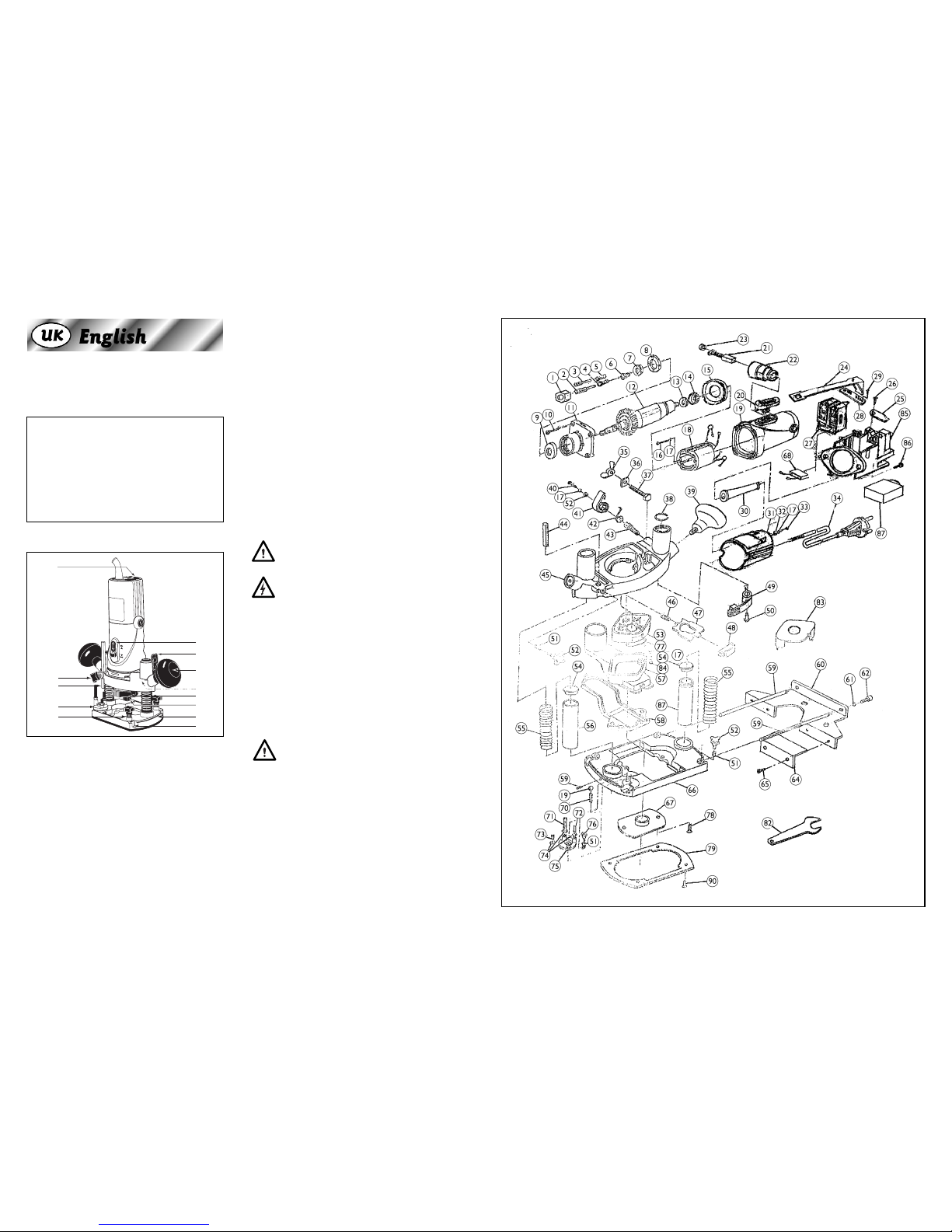
EXPLODED VIEW
Page 3

6 Ferm
SPARE PARTS LIST FBF-850E
REF NR DESCRIPTION FERM NR
001 COLLET NUT 312009
002 ROUTER 312014
004 SPRING COLLET 8 MM 312008
005 SPRING COLLET 6 MM 312012
012 ROTOR 302051
018 STATOR 302052
020 SWITCH ACTUATOR 302053
021 CARBON BRUSH SET 302054
023 CARBON BRUSH CAP 302055
024 PULL ROD 302056
027 SWITCH 302057
039 KNOB 302058
041 LOCKING LEVEL 302059
042 TWIST SPRING 302060
044 DEPTH RULER 302061
052 KNOB 302002
057 + 058 DUST COLLECTOR 302062
059 UNTIL 065 GUIDE COMPLETE 302063
082 WRENCH 312011
087 PCB FOR VARIABLE SPEED 302064
Dress properly
Do not wear loose clothing or jewellery. It can get
caught in moving parts. Non-skid footwear is
recommended when working out doors. Wear
protective hair covering to contain long hair.
Stay alert
Watch what you are doing Use common sense. Do not
operate tools when tired or after taking alcohol or
prescription/ non-prescription drugs.
OPERATIONAL SAFETY
Warning! Always make sure the machine is
switched off and unplugged when its not being
used, you are changing cutters or moving the work piece. See
safe work order summary section for details
Be aware: this is a powerful machine and requires two hands
to operate it.
Concentrate
Routine and repetition can lead to mistakes. Remember
that a slight lack of concentration can result in serious
injuries in a split second.
Keep work area clean
Cluttered areas and benches invite injuries.
Consider the work environment
Do not expose power tools to rain or use them in damp
or wet locations. Keep work area well lit. Do not use
power tools in the presence of flammable liquids,
vapours or gases.
Guard against electric shock
This unit contains dangerous voltages. Use a RCD
(residual current device) to provide protection against
electrical shock. Prevent body contact with grounded
surfaces (e.g. pipes, radiator, ranges or refrigerators).
Keep children and pets away
Do not let children or pets come into contact with the
tool, extension cable or work area.
Do not force the tool
It will work better and safer at the rate for which it was
intended.
Use the right tool
Do not force small tools or attachments to do the job of
a heavy-duty tool. Do not use tools for purposes for
which they were not intended; for example do not use a
circular saw for cutting trees or logs.
Do not abuse the cable
Never carry the tool by the cable or pull it to disconnect
it from the power socket. Keep the cable away from
heat, oil and sharp edges. Do not touch the metal plug
pins when connecting or removing the plug.
Secure work
Use clamps or a vice to hold work. It is safer than using
your hand and it frees both hands to operate the tool. Be
aware that this router is a powerful machine; you must
use two hands to control it.
Do not over-reach
Keep a proper footing and balance at all times.
Disconnect tools from power supply
When not in use, before servicing and when changing
accessories such as blades, bits and cutters.
Always switch off and unplug the router from the
power supply before making adjustments or
changing cutters.
Remove adjusting keys and wrenches
Ensure that they are removed from the tool before
switching on.
Avoid unintentional starting
Do not carry plugged in tools with your finger on the
switch. Check that the switch is off before plugging in to
socket.
Extension cables
Use only three core earthed extension cables suitable
for the power input of the tool (minimum cable size
1.5mm2). Plug into an earthed socket only.
When using a cable reel unwind it fully. Do not use long
extension cables.
Outdoors use
If the tool is suitable to be used outdoors, only use an
extension cable intended for outdoor use and marked
accordingly. Use a RCD (residual current device) to
provide protection against electrical shock. Do not use
in rain or damp conditions.
Connect a dust extraction device
Whenever there are facilities for fitting a dust or fume
extraction system, make sure it is connected and used.
Use recommended accessories
The use of any other accessory or attachment other
than recommended in the instructions or catalogue may
present a risk of personal injury. Use extension cables
suitable for the power input of the machine (minimum
cable size 1.5mm
2
). When using a cable reel unwind the
cable fully.
Ferm 3
Page 4

Ferm 5
MOUNTING ACCESSORIES
Fig.B
Prior to mounting an accessory always unplug the
tool.
MOUNTING AND REMOVING CUTTERS
Only use cutters with a shaft diameter which
corresponds with the size of the collet. Only use cutters
which are suited for the maximum speed of the machine.
The cutter diameter should not exceed the maximum
diameter (see ‘Technical specifications’).
• Press in the spindle lock (5) and turn the springchuck nut (6) until it drops into the lock. Keep the
spindle lock pressed in as long as you are following
this procedure.
• Use the open-end wrench to unscrew the springchuck nut.
• Place the cutter shaft in the collet.
• Tighten the collet nut so that the cutter is locked
properly.
• Open the collet nut when you want to replace a
cutter.
Wait until the machine has come to a complete
standstill and the cutter has cooled down before
replacing a cutter.
MOUNTING AND ADJUSTING THE
PARALLEL GUIDE
Fig.C
The parallel guide is a handy aid when working on
narrow workpieces.
• Mount the parallel guide. Attach the guide rods (15)
on the frame (14) using the bolts (16).
• Loosen the locking bolts (9) and slide the guide rods
in the openings (8).
• Adjust the parallel guide to the desired guide
distance.
• Tighten the locking bolts again.
MOUNTING THE GUIDE BUSH
Fig.D
The guide bush is a handy aid for cutting a pattern.
• Mount the template guide (20) by using the screws
(17) on the cutter sole.
17
20
15
16
9 8 14
6
5
4 Ferm
Page 5

MOUNTING THE ADAPTER FOR DUST
EXTRACTION
Fig.E
Use the adapter for extracting dust.
• Remove the spring-chuck nut as mentioned in ‘Fitting
and removing cutter bits’ (Fig. B).
• Loosen the clamp screw (2) for the machine and
remove the machine from the base.
• Remove the clamp screws for the parallel guide (9)
on the back of the machine.
• Mount the adapter for vacuum cleaning (18) by using
the screws (17) on the cutter sole (7).
• Place the clamp screws for the parallel guide back on
the cutter sole.
• Place the machine back in the base and tighten the
clamp screw.
• Place the spring chuck nut back on the machine.
• Place the mouthpiece of a vacuum cleaner on the
outlet of the adapter.
Keep the outlet of the machine behind the machine
for a good view on the workpiece.
OPERATION
Always observe the safety instructions and
applicable regulations.
Hold the machine in rest position on the workpiece
when switching the machine on or off. The cutter in the
collet may damage the workpiece.
• Clamp the workpiece and make sure that the
workpiece cannot slide from under the machine
during the cutting activities.
• Hold the machine firmly and move it evenly over the
workpiece. Do not force the machine.
• Only use cutters which do not show any signs of
wear. Worn cutters have a negative effect on the
efficiency of the machine.
• Always switch off the machine first before removing
the plug from the wall socket.
ADJUSTING THE CUTTING DEPTH
Fig.F
The cutting depth can be adjusted in two ways.
Adjustment using the scale
• Loosen the locking bolt of the depth stop (12).
• Release clamping lever (3) and press the machine so
far down until the cutter touches the workpiece.
• Tighten the clamping lever again.
• Set the desired cutting depth using the graduated
scales (11) and then tighten the clamp screw.
Adjustment using the revolver- depth stop
The revolver-depth stop enables you to quickly choose
between three different cutting depths. These are also
determined by the adjustment of the depth scale (11).
• Adjust the required cutting depth by the three
screws on the revolver-depth stop (10).
3
12
10
11
18
2
19
17
7
9
Ferm 109 Ferm
Page 6

Have your tool repaired by an expert
This appliance is manufactured in accordance with
relevant safety standards. Only experts must carry out
repairing of electrical appliances, otherwise
considerable danger for the user may result.
Storing tools
When not in use tools should be stored in the dry, out of
reach of children.
LUBRICATION
The machine requires no user lubrication
ELECTRICAL INFORMATION
This product is complete with a pre-wired mains plug, it
is double insulated in accordance with EN 50144 – no
earth wire is required.
If the plug needs replacing follow these instructions.
Wire correctly
The wires in the mains lead are coloured in the following
way:
BLUE • Neutral
BROWN • Live
Secure wires
Secure wires carefully and firmly to the correct
terminals. Secure the mains cable in the plug cord grip
firmly.
Fit a 13-amp fuse. If a 13amp (BS1363) plug is used a (BS
1362) ASTA approved 13-amp fuse must be fitted.
Recycle/Dispose of old plug and cable
Prevent inadvertent connection to socket and risk of
electric shock.
ENVIRONMENT
Recycle the packaging according to the identification
marks on it.
At the end of the product or its accessories life please
recycle where facilities exist - phone the Helpline for
current advice on recycling.
HELPLINE
For any queries relating to operational or safety
matters contact:
Ferm Customer Helpline on: 0115 966 1199
Monday-Friday 8am – 6pm
Saturday 9am – 1 pm
GUARANTEE
The guarantee conditions can be found on the separately
enclosed guarantee card.
We declare under our sole responsability that this
product is in conformity with the following
standards or standardized documents
EN50144-1, EN50144-2-17,
EN55014-1, EN55014-2,
EN61000-3-2, EN61000-3-3,
in accordance with the regulations.
98/37EEC
73/23EEC
89/336EEC
from 24-01-2003
GENEMUIDEN NL
W. Kamphof
Quality department
CE
ı
DECLARATION OF CONFORMITY
(UK)
Blue
(Neutral)
Green & Yellow
(Earth)
Brown
(Live)
Fuse
(13 Amp)
Ferm 12
SWITCHING ON AND OFF
Fig.G
• Depress the on/off switch (1) to switch the machine
on. Then push the switch through its resistance to
lock the switch in the on position. The cutter speed
can be adjusted by means of the adjusting wheel (13).
• Release the on/off switch to switch the machine off
or push the switch again when it is in locked position.
Always select a low speed for cutting plastic
workpieces.
Do not put the machine down when the motor is still
running. Do not place the machine on a dusty surface.
Dust particles may enter the mechanism.
MAINTENCE, CARE AND
REPAIR
Switch off and unplug the machine before carrying
out any cleaning, adjusting or changing blades.
CLEANING
Do not use water or flammable liquids to clean the
router.
FAULTS
Switch OFF immediately at the mains plug and
remove the plug when:
• The plug or cable is damaged.
• The switch on the machine is defective.
• You smell or see smoke caused by scorched
insulation in the machine.
The motor runs hot (over 70°C)
• The motor has been overloaded, cut more slowly.
• The motor is defective; take to your local dealer for
repair.
The router does not work when switched on
• Damaged plug/fuse, replace as required.
• Defective switch, take to local dealer for repair.
The router does not cut cleanly or wanders off
line.
• The cutter is blunt or bent, replace with suitable
resharpened or new one.
The router makes a lot of noise and does not run
smoothly.
• The carbon brushes need replacing.
Take to your local dealer for inspection or repair.
There are no user serviceable/repairable parts inside
this unit. Qualified service engineers must carry out
repair and servicing.
MAINTAIN TOOLS WITH CARE
Keep the tool clean for better and safer performance.
Store the cutters properly in accordance with the
maker’s instructions.
Follow instructions for changing accessories. Inspect
tool and extension cables periodically and if damaged,
have them repaired by a qualified person or authorised
service body. Keep handles free from oil or grease. Keep
the ventilation slots clean to prevent the motor
overheating.
Check for damaged parts
Do not use a tool with damaged parts, before further use
a damaged tool must be carefully checked by a qualified
person to determine that it will operate properly. Check
for alignment of moving parts, binding or breakage of
parts, mounting and other conditions that may affect its
operation. A damaged part or guard should be properly
repaired by an authorised service centre, unless
indicated otherwise in the instruction manual. Have
defective switches replaced by an authorised service
centre. Do not use a tool if the switch does not turn on
and off.
6
1
13
11 Ferm
 Loading...