

Page 1

Art. No. SCM8001
Model. No. RCT-600
4 A Rotary Cutting Tool
with Circle Cutting Guide
www.ferm.com
www.ferm.com 0611-24
USA Subject to change
CAUTION:
Before using this Rotary
Cutting Tool or any of its
accessories, read this
manual and follow all Safety
Rules and Operating
Instructions.
Imported by Ferm BV
• General Safety Rules
• Specific Safety Rules and
Symbols
• Functional Description
• Assembly
• Operation
• Maintenance
• Accessories
Page 2

Ferm 27
Exploded view
02 Ferm
30 26 28 24 20 22 18 16 14 12 10
A
J
H
I
G
F
B
D
C
E
Ill.1
Page 3
Ferm 03
D
NL
F
E
P
I
S
SF
N
DK
26 Ferm
Spare parts list
WARNING: When servicing, use only FERM replacement parts. Use of any other parts
may create a safety hazard or cause damage to the tool.
Any attempt to repair or replace electrical parts on this power tool may create a safety
hazard unless repair is performed by a qualified technician.
Always order by PART NUMBER, not by key number.
Position Description No.
2 Switch 400910
3 till 5 Spindellock complete 400911
6, 18, 19, 20 Base support complete 400912
8, 10 till 15, 17 Guide complete 400913
7, 9 , 16 Base plate complete 400914
22 Collet nut 400915
23 Collet 1/4” 400916
25 Bearing 6002ZZ 806002
37 Bearing 608ZZ 800608
42 Collet 1/8” 400917
- Carbon brushes 400918
UK
D
NL
F
E
P
I
S
SF
N
DK
30 26 28 24 20 22 18 16 14 12 10
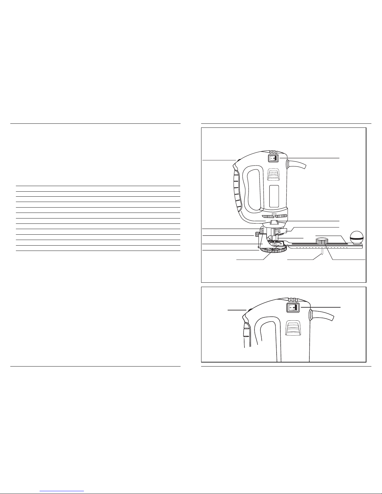
Speed control wheel
Free hand guide foot
Mounting disc
Pivot pointMounting insert
ON/OFF switch
Spindle locking button
Locking lever
Collet nut
Circle cutting guide
Pivot point knob
Free hand cutting guide collar
Depth gauge locking screw
Ill.2
2
1
Ill.3
Page 4
Ferm 25
UK
D
NL
F
E
P
I
S
SF
N
DK
04 Ferm
3
1
2
4
Ill.4
4
32
1
Ill.5
1
2
3
Ill.6
Page 5

Ferm 05
GB
D
NL
F
E
P
I
S
SF
N
DK
24 Ferm
UK
D
NL
F
E
P
I
S
SF
N
DK
2
1
Ill.7
Ill.8
Ill.9
Page 6

Ferm 23
UK
D
NL
F
E
P
I
S
SF
N
DK
06 Ferm
D
NL
F
E
P
I
S
SF
N
DK
Ill.10
Ill.11
30 26 28 24 20 22 18 16 14 12 10
1
3
4
2
5
6
9
7
8
Ill.12
Page 7

Ferm 07
D
NL
F
E
P
I
S
SF
N
DK
22 Ferm
An undersized cord will cause a drop in line voltage resulting in loss of power and overheating.
The table below shows the correct size to use according to cord length and nameplate amp.
rating. If in doubt, use the next heavier gauge. The smaller the gauge number the heavier the
cord.
Be sure your extension cord is properly wired and in good condition. Always replace a
damaged extension cord or have it repaired by a qualified electrician before using it. Protect
your extension cord from sharp objects, excessive heat and damp or wet areas.
Use a separate electrical circuit for your power tools. This circuit must not be less than 14
gauge wire and should be protected with either a 15 A time delayed fuse or circuit breaker.
Before connecting the power tool to the power source, make sure the switch is in the OFF
position and the power source is the same as indicated on the nameplate. Running at lower
voltage will damage the motor.
MINIMUM GAUGE (AWG) EXTENSION CORDS
(120 V use only)
Ampere Rating Total length in feet
More than Not more than 25’ 50’ 100’ 150’
0 6 18 16 16 14
6 10 18161412
10 12 16 16 14 12
12 16 14 12 Not applicable
WARNING: Keep the extension cord clear of the working area. Position the cord so
it will not get caught on the workpiece, tools or any other obstructions while you are
working with the power tool.
UK
D
NL
F
E
P
I
S
SF
N
DK
30 26
28
24
20
22
18
16
14
12
10
Ill.13
30 26 28 24 20 22 18 16 14 12 10
Ill.14
Page 8

Ferm 21
GENERAL
WARNING: When servicing, use only identical replacement parts. Use of any other
part may create a hazard or cause product damage.
DO NOT use solvents when cleaning plastic parts. Plastics are susceptible to damage from
various types of commercial solvents and may be damaged by their use. Use a clean cloth to
remove dirt, dust, oil, grease etc.
WARNING: Do not at any time allow brake fluids, gasoline, petroleum-based
products, penetrating oils, etc. to come into contact with plastic parts. They
contain chemicals that can damage, weaken or destroy plastic.
DO NOT abuse power tools. Abusive practices can damage the tool as well as the workpiece.
WARNING: DO NOT attempt to modify tools or create accessories. Any such
alteration or modification is misuse and could result in a hazardous condition
leading to possible serious injury. It will also void the warranty.
Lubrication
All of the bearings in this tool are lubricated with a sufficient amount of high-grade lubricant for
the life of the unit under normal conditions. Therefore, no further lubrication is required.
Make sure any extension cord used with this tool is in good condition. When using an
extension cord, be sure to use one of heavy enough gauge to carry the current the tool will
draw.
Warning!
Have you read “POWER TOOL SAFETY”, “ROTARY CUTTING TOOL SAFETY” and
“SYMBOLS” on pages 9 till 13 of this Manual? If not, please do so now before you
operate this Rotary Cutting Tool. Your safety depends on it!
Every time you use the Rotary Cutting Tool you should verify the following:
1. Bit is sharp and in good condition.
2. Bit is securely fastened in the collet.
3. Workpiece is properly secured.
4. Safety glasses are being worn.
Failure to adhere to these safety rules can greatly increase the chances of injury.
GUIDELINES FOR EXTENSION CORDS
MAINTENANCE
UK
D
NL
F
E
P
I
S
SF
N
DK
08 Ferm
SECTION PAGE SECTION PAGE
Warranty 8 Accessories 13-14
Product specifications 9 Carton contents 14
Power tool safety 9–11 Assembly & Operation 14-20
Rotary cutting tool safety 11 Maintenance 21
Symbols 12-13 Guidelines for extension cords 21-22
Know your Rotary Cutting Tool 13 Parts & Service 26
WARNING: Some dust created by sanding, sawing, grinding, drilling and other
construction activities contains chemicals known to cause cancer, birth defects or
other reproductive harm. Some examples of these chemicals are:
• Lead from lead-based paints
• Crystalline silica from bricks, cement and other masonry products
• Arsenic and chromium from chemically-treated lumber
Your risk from these exposures varies, depending on how often you do this type of work. To
reduce your exposure to these chemicals, work in a well-ventilated area and work with
approved safety equipment such as dust masks or respirators specifically designed to filter
out microscopic particles.
1-year Warranty
This Ferm product carries a one (1) year warranty against defects in workmanship and
materials. We agree to replace the defective product free of charge with the same
model or one of equal value or specification, within the stated warranty period, when
returned by the original purchaser with proof of purchase. This product is not
guaranteed against wear or breakage due to misuse and/or abuse.
This product is not guaranteed if used for industrial or commercial purposes.
TOLL FREE HELPLINE: 888-520-FERM (3376)
WARRANTY
TABLE OF CONTENTS
GB
D
NL
F
E
P
I
S
SF
N
DK
Page 9

Ferm 09
WARNING: To avoid electrical hazards, fire hazards or damage to the cutting tool,
use proper circuit protection.
This tool is wired at the factory for 110–120 V operation. It must be connected to a 110–120 V,
15 A time delayed fuse or circuit breaker. To avoid shock or fire, replace power cord
immediately if it is worn, cut or damaged in any way.
SAVE THESE INSTRUCTIONS FOR REFERENCE
GENERAL SAFETY RULES
WARNING: Read and understand all instructions. Failure to follow all instructions
listed below may result in electric shock, fire and/or serious personal injury.
Work area
• Keep your work area clean and well lit. Cluttered benches and dark areas invite
accidents.
• Do not operate power tools in potentially explosive environments, such as in the
presence of flammable liquids, gas or dust. Power tools create sparks which may ignite
the dust or fumes.
• Keep bystanders, children and visitors away while operating the tool. Distractions can
cause you to lose control.
ELECTRICAL SAFETY
• Double insulated tools are equipped with a polarized plug (one blade is wider than the
other). This plug will fit in a polarized plug only one way. If the plug does not fit fully in
the outlet, reverse the plug. If it still does not fit, contact a qualified electrician to
install a polarized outlet. Do not alter the plug in any way. Double insulation eliminates
the need for the three-prong grounded power cord and grounded power supply system.
• Avoid body contact with grounded surfaces such as pipes, radiators, ranges and
refrigerators. There is increased risk of electric shock if your body is grounded.
• Do not expose power tools to rain or wet conditions. Water entering the power tool will
increase the risk of electric shock.
POWER TOOL SAFETY
Motor rating 120 V, 60 Hz, AC
Amperes 4.0 A
Variable speed (no load) 15000–30000 RPM
PRODUCT SPECIFICATIONS
GB
D
NL
F
E
P
I
S
SF
N
DK
20 Ferm
4. Screw the internally-threaded circle cutting guide mounting disc (7) onto the externallythreaded circle cutting guide mounting insert and hand tighten.
NOTES:
a) Make sure the boss (8) on the cutting guide mounting disc goes through the hole in
the circle guide.
b) Do not over tighten the circle cutting guide mounting plastic parts. Hand tighten only.
5. Adjust the circle cutting guide radius by loosening pivot point knob (9), sliding it to the
correct circle radius and re-tightening in the desired location.
NOTE: Check circle cutting guide radius setting by measuring from the pivot point to the
outside of the cutting bit.
Circle guide operation
Ill.13+14
WARNING: Unplug the tool from the power source before changing accessories,
changing bits and making adjustments.
Before turning the tool ON, check to make sure bit and all accessory fasteners are
securely tightened.
1. Mark the centre of the circle you wish to cut on the workpiece and drill a 6 mm or 1/4” pilot
hole.
2. Adjust cutting bit depth to 1/8” longer than the thickness of the material being cut (Ill. 7).
3. Adjust the circle cutting guide radius by loosening pivot point knob, sliding it to the correct
circle radius and re-tightening in the desired location.
NOTE: Check circle cutting guide radius setting by measuring from the pivot point to the
outside of the spiral bit.
4. Rest the edge of the freehand cutting guide on the workpiece with the bit at an angle of
about 45° (Ill. 13). Insert the circle cutting guide pivot point into the pilot hole drilled at the
centre of the circle.
NOTE: DO NOT let the bit touch the workpiece before switch is turned ON and the tool is
up to full speed.
5. Turn the switch ON.
6. When the motor is up to full speed, slowly tip the tool and circle cutting guide assembly to
an upright position, letting the bit cut into the workpiece. Be careful to keep the pivot point
located at the centre of the circle to be cut. Once the tool has reached the upright position
and the bit has cut through the workpiece, slowly move the tool in a clockwise direction
using slow steady pressure to make the cut. Continue to cut the circle, keeping the tool
upright and rotating around the circle cutting guide pivot point.
7. When cut is complete, turn the tool OFF, wait until it comes to a complete stop and remove
it from the workpiece.
UK
D
NL
F
E
P
I
S
SF
N
DK
Page 10

Ferm 19
4. Install cutting bit and freehand cutting guide as outlined on pages 15-16 of this manual.
Adjust depth of cut so the bit will protrude 1/8” beyond the thickness of the drywall.
5. Hold the tool firmly with both hands and turn it ON. Plunge the bit through the drywall at
the mark indicating the centre of the box. See Ill. 10 for cutting pattern.
6.
Move the bit slowly to the right until you feel and hear the bit contacting the inside of the box.
7. Pull the bit out far enough to slip it over the edge of the box. Once the bit is outside the box,
push it back to full depth beside the outside edge of the box.
8. Move the tool upward while applying slight pressure toward the centre of the box. When
you feel the bit reach the top right corner of the box, move the tool to the left while applying
slight pressure downward toward the centre of the box.
9. Continue moving the tool around the box in a counter-clockwise direction while
maintaining slight pressure toward the centre of the box. When the box cut-out is
complete, turn the tool OFF and remove it from the cut-out.
10. Completed electrical box cut-out will be accurately and neatly cut.
NOTE: Always move the cutting bit in a counter- clockwise direction around the outlet box.
The natural tendency of the cutting bit to move to the left will make it easier to cut close to the
box.
Installing circle cutting guide
Ill.12
The circle cutting guide accessory is ideal for precision cutting of circles. This circle cutting
guide must be attached to the freehand cutting guide.
1. Install freehand cutting guide on the tool as illustrated on page 16 of this owner’s manual.
2. Insert the externally-threaded circle cutting guide mounting insert (1) into the bottom of
the freehand cutting guide (2).
NOTE: Make sure the notches (3) in the mounting insert are inserted into the matching
keys (4) in the sides of the cutting guide foot.
3. Place circle cutting guide mounting hole (5) over the externally-threaded circle cutting
guide mounting insert.
NOTE: Make sure pointed pivot pin (6) is pointing away from the tool.
Warning!
Have you read “POWER TOOL SAFETY”, “ROTARY CUTTING TOOL SAFETY” and
“SYMBOLS” on pages 9 till 13 of this Manual? If not, please do so now before you
operate this Rotary Cutting Tool. Your safety depends on it!
Every time you use the Rotary Cutting Tool you should verify the following:
1. Bit is sharp and in good condition.
2. Bit is securely fastened in the collet.
3. Workpiece is properly secured.
4. Safety glasses are being worn.
Failure to adhere to these safety rules can greatly increase the chances of injury.
UK
D
NL
F
E
P
I
S
SF
N
DK
10 Ferm
• Do not abuse the cord. Never use the cord to carry the tool or pull the plug from an outlet.
Keep cord away from heat, oil, sharp edges or moving parts. Replace damaged cords
immediately. Damaged cords increase the risk of electric shock.
• When operating a power tool outdoors, use an outdoor extension cord marked “W-A”
or “W”. These cords are rated for outdoor use and reduce the risk of electric shock.
PERSONAL SAFETY
• Stay alert, watch what you are doing and use common sense when operating a power
tool. Do not use the tool while tired or under the influence of drugs, alcohol or
medication. A moment of inattention while operating power tools may result in serious
personal injury.
• Dress properly. Do not wear loose clothing or jewellery.
• Contain long hair. Keep your hair, clothing and gloves away from moving parts. Loose
clothing, jewellery or long hair can be caught in moving parts.
• Avoid accidental starting. Be sure switch is OFF before plugging in. Carrying tools with
your finger on the switch or plugging in tools that have the switch ON invites accidents.
• Remove adjusting keys or wrenches before turning the tool ON. A wrench or key that is
left attached to a rotating part of the tool may result in personal injury.
• Do not overreach. Keep proper footing and balance at all times. Proper footing and
balance enables better control of the tool in unexpected situations.
• Use safety equipment. Always wear eye protection. Dust mask, non-skid safety shoes,
hard hat or hearing protection must be used for appropriate conditions.
TOOL USE AND CARE
• Use clamps or another practical way to secure and support the workpiece to a stable
platform. Holding the work by hand or against your body is unstable and may lead to loss
of control.
• Do not force the tool. Use the correct tool for your application. The correct tool will do
the job better and safer at the rate for which it was designed.
• Do not use the tool if the power switch does not turn it ON or OFF. Any tool that cannot
be controlled with the switch is dangerous and must be repaired.
• Disconnect the plug from the power source before making any adjustments,
changing accessories or storing the tool. Such preventive safety measures reduce the
risk of starting the tool accidentally.
• Store idle tools out of reach of children and other untrained persons. Tools are
dangerous in the hands of untrained users.
• Maintain tools with care. Keep cutting tools sharp and clean. Properly maintained
cutting tools with sharp cutting edges are less likely to bind and are easier to control.
• Check for misalignment or binding of moving parts, breakage of parts and any other
condition that may affect the tool’s operation. If damaged, have the tool serviced
before using. Many accidents are caused by poorly maintained tools.
• Use only accessories that are recommended by the manufacturer for your model.
Accessories that may be suitable for one tool may become hazardous when used on
another tool.
GB
D
NL
F
E
P
I
S
SF
N
DK
Page 11

Ferm 11
SERVICE
• Tool service must be performed only by qualified personnel. Service or maintenance
performed by unqualified personnel could result in risk of injury.
• When servicing a tool, use only identical replacement parts. Follow instructions in the
Maintenance section of this manual. Use of unauthorized parts or failure to follow
Maintenance instructions may create a risk of electric shock or injury.
SPECIFIC SAFETY RULES
WARNING: For your safety, do not plug in your cut out tool or install a bit or
attachment until you have read and understood this Owner’s Manual.
• Wear eye protection. Use face or dust mask along with safety goggles if operation is
dusty. Use hearing protection, particularly during extended periods of operation.
• Do not wear gloves, neckties or loose clothing.
• Do not drill, cut or sand material that is too small to be securely held.
• Always keep hands out of the path of the bit. Avoid awkward hand positions where your
hand could move into the path of the bit.
• Secure workpiece. Use clamps or a vice to hold the work when practical. Use both hands
to guide the tool.
• Make sure there are no nails or foreign objects in the part of the workpiece to be cut, drilled
or sanded.
• Hold tool by insulated gripping surfaces when performing an operation where the
cutting tool may contact hidden wiring or its own cord. Contact with a “live” wire will
make exposed metal parts of the tool “live” and shock the operator.
• Always make sure the work surface is free from nails and other foreign objects.
Cutting into a nail can cause the bit and the tool to jump and damage the bit.
• Always use a safe method to secure the workpiece, and use both hands to guide the
tool. Never place hands near or below the cutting surface.
• Never lay workpiece on hard surfaces like concrete, stone, etc. Protruding cutting bit
may cause tool to jump.
• Always wear safety goggles and dust mask. Use only in well-ventilated area. Using
personal safety devices and working in a safe environment reduces risk of injury.
• After changing the bits or making adjustments, make sure the collet nut and any
other adjustment devices are securely tightened. Loose adjustment devices will be
violently thrown.
• Never use dull or damaged bits. Sharp bits must be handled with care. Damaged bits
can snap during use. Dull bits require more force to push the tool, possibly causing the bit to
break.
• Never touch the bit during or immediately after use. After use the bit is too hot to be
touched by bare hands.
ROTARY CUTTING TOOL SAFETY
UK
D
NL
F
E
P
I
S
SF
N
DK
18 Ferm
7. Turn the switch ON.
8. When the motor is up to full speed, slowly tip the tool to an upright position, letting the bit
cut into the workpiece (Ill. 9). Once the tool has reached the upright position and the bit
has cut through the workpiece, slowly move the tool in a clockwise direction using slow
steady pressure to make the cut.
NOTE: Except for cutting around outlet boxes in drywall, always cut in a clockwise
direction.
9. When cut is complete, turn the tool OFF, wait until it comes to a complete stop and remove
it from the workpiece.
DANGER: Do not attempt cutting around outlet boxes in drywall until:
1. All electricity in the vicinity of electric wires has been disconnected by either turning the
breaker OFF or removing the fuses.
2. You have read the instructions on the following page entitled “CUTTING OUTLET
OPENINGS IN DRYWALL”.
Cutting tips
The rotating cutting action of the bit will cause a slight pull to the left when cutting. Natural
variations in the structure of wood will cause the bit to “wander”. This tendency will be
magnified when applying too much pressure to the bit. Slower cutting gives you better
control. Excessive pressure or fast cutting will increase bit temperature and shorten the life of
the bit.
When cutting a hole in a vertical surface, avoid ending the cut at the bottom of the hole. Always
start and end the cut at the “top” so the cut-out part will not drop onto the rotating bit. Always
turn the tool OFF before removing it from the workpiece
Cutting outlet openings in drywall
Ill.10+11
DANGER: Do not attempt to use this tool to make cut-outs around any fixture or
opening which has live electrical wires or on any wall which may have electrical
wiring behind it. If a live wire is contacted, the bit could conduct the electric current
to the tool, creating an electrocution hazard for the operator. Turn OFF breakers or
remove fuses to disconnect the electric circuit in the area of work. Always hold the
tool by its insulated housing when working in areas where there is a possibility of
contacting electric wires. Always wear eye protection when operating this tool.
1. Before installing drywall, push the electrical wires to the back of the outlet box as far as
possible so they will not be cut by the bit when cutting the opening.
2. Before fastening the drywall sheet over the electrical box, mark the sheet as close as
possible to the centre of the box opening. Mark should be on the side of the drywall facing
you.
3. When fastening the drywall in place, do not place nails or screws closer than 12” from the
box. This will prevent the drywall from becoming deformed under pressure.
UK
D
NL
F
E
P
I
S
SF
N
DK
Page 12

Ferm 17
Adjusting freehand cutting guide
Ill.7
1. Adjust freehand cutting guide depth by loosening the depth gauge locking screw (1) and
moving the cutting guide foot in or out as required.
NOTE: Set the foot so the cutting bit protrudes beyond the cutting guide 1/8” more than
the thickness of the material being cut. For example, if you are cutting 5/8” drywall, the bit
should protrude 3/4” beyond the cutting guide.
2. Securely tighten depth gauge locking screw.
NOTE: Hand tightening is normally adequate. If you use a screwdriver (2), do not
overtighten the locking screw.
3. Before starting to cut, double-check the bit depth. Make sure the cutting guide is at a right
angle to the bit and securely tightened. Double-check the collet to make sure the bit is
securely fastened.
Practice cuts using the freehand cutting guide
Ill.8+9
Before attempting to work on an actual project, take the time to make a few practice cuts with
your Rotary Cutting Tool. Use some scraps of material that are the same material as will be
used in your actual project.
1. Draw a pattern similar to your first project on a scrap piece of material.
2. Install freehand cutting guide as shown in Ill. 6.
3. Install cutting bit in the collet as shown in Ill. 4.
4. Adjust depth of freehand cutting guide as shown in Ill. 7.
5. Rest the edge of the cutting guide on the workpiece with the bit at an angle of about 45°.
NOTE: DO NOT let the bit come into contact with the workpiece until the power switch is
turned ON and the tool is up to full speed.
WARNING: Before turning the power switch ON, make sure you are holding the
tool firmly with both hands. Starting torque will cause the tool to twist.
6. Set the speed control switch to the appropriate speed.
Warning!
Have you read “POWER TOOL SAFETY”, “ROTARY CUTTING TOOL SAFETY” and
“SYMBOLS” on pages 9 till 13 of this Manual? If not, please do so now before you
operate this Rotary Cutting Tool. Your safety depends on it!
Every time you use the Rotary Cutting Tool you should verify the following:
1. Bit is sharp and in good condition.
2. Bit is securely fastened in the collet.
3. Workpiece is properly secured.
4. Safety glasses are being worn.
Failure to adhere to these safety rules can greatly increase the chances of injury.
UK
D
NL
F
E
P
I
S
SF
N
DK
12 Ferm
WARNING: Some of the following symbols may be used on your tool. Please study
them and learn their meaning. Proper interpretation of these symbols will allow
you to operate the tool better and safer.
V volts
A amperes
Hz hertz
W watt
kW kilowatts
ÌF microfarads
L litres
Kg kilograms
H hours
N/cm
2
newtons per square centimeter
Pa pascals
Min minutes
S seconds
alternating current
three-phase alternating current
three-phase alternating current with neutral
direct current
n
0
no load speed
SYMBOLS
UK
D
NL
F
E
P
I
S
SF
N
DK
Page 13

Ferm 13
alternating or direct current
class II construction
splash proof construction
watertight construction
protective earthing at earthing terminal, Class I tools
../min revolutions or reciprocations per minute
Ø diameter
0 off position
arrow
warning symbol
This symbol designates that this tool is listed with both Canadian and U.S.
requirements by Underwriters Laboratories.
See Ill.2 at page 03 in front of the manual.
Available accessories
WARNING: Use only accessories recommended for this cut out tool. Follow
instructions that accompany accessories. Use of improper accessories may cause
injury to the operator or damage to the tool.
ACCESSORIES
KNOW YOUR ROTARY CUTTING TOOL
UK
D
NL
F
E
P
I
S
SF
N
DK
16 Ferm
Before tightening the collet on the bit, make sure the flutes (spiral portion) of the bit
are completely visible outside the collet. Clamping the collet on the bit flutes will
result in broken bits and possible injury.
5. When the bit is properly placed in the collet, depress the shaft locking button and turn the
collet nut clockwise by hand as far as possible.
6. Securely tighten the collet nut using the wrench.
SELECT APPROPRIATE MOTOR SPEED
Selecting the appropriate motor speed for your application will ensure smoother, more
efficient cutting action. Choose LOWER speed for cutting plastics. Choose HIGHER speed
when cutting wood and drywall, and to reduce “chatter” that may develop when cutting some
materials at LOW speed.
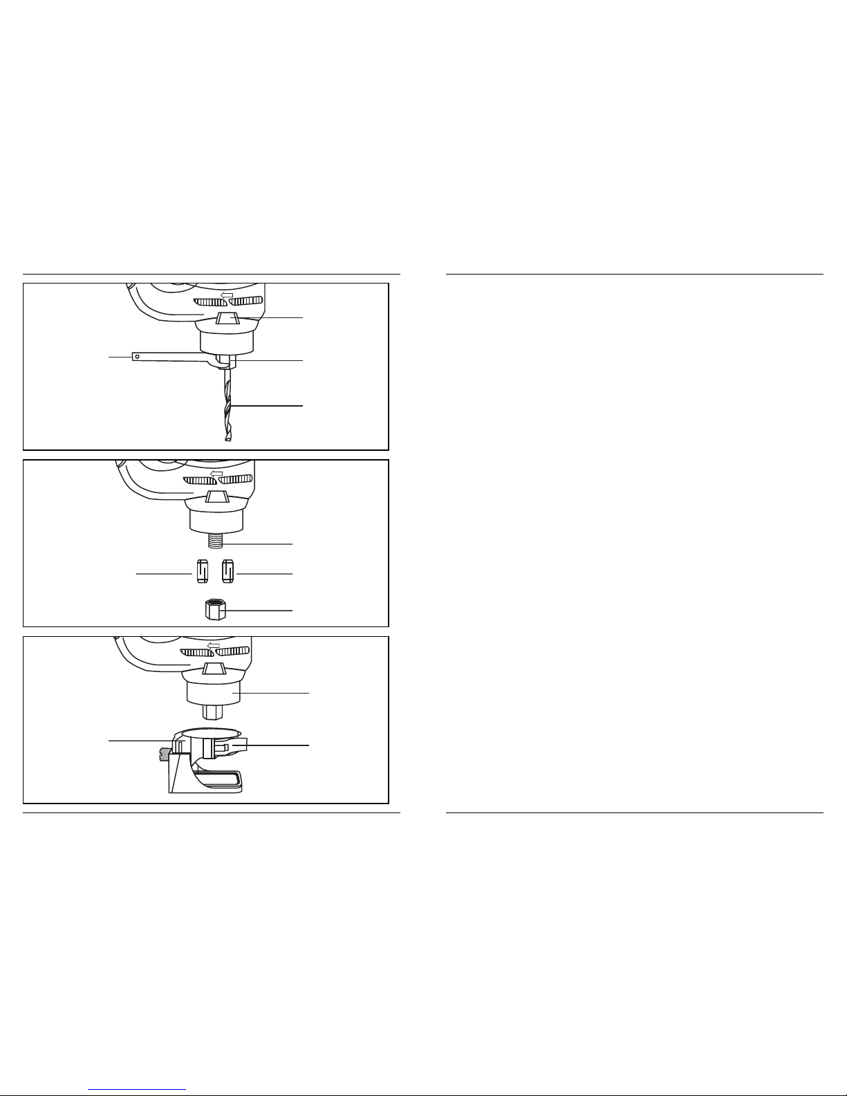
Change collet
Ill.5 + 6
The cutting bits for this tool are locked into place with a collet nut (1) and collet (Ill. 5). The 1/8”
collet (2) is used for holding 1/8” cutting bits and hobby tool accessory bits. The 1/4” collet (3)
is supplied for holding 1/4” bits.
To change from one collet size to the other:
1. Remove bit from the tool.
2. Turn the collet nut counter clockwise until it can be removed from the motor shaft (4).
3. Pull the collet out of the motor shaft and insert the new collet.
NOTE: Each collet is the same on both ends, so either end can be inserted into the motor
shaft.
4. Re-install the collet nut and slightly tighten it by hand.
NOTES:
a) Tightening the collet nut without a bit in the collet will cause the collet hole to become
smaller and make installing bits difficult. When storing the tool with no bit installed, leave
the collet nut loose.
b) Install the new bit as outlined in INSTALLING CUTTING BITS .
Installing freehand cutting guide
Ill.6
The freehand cutting guide is designed for basic freehand cutting with the cutting bit. It is
ideally suited for cutting electrical outlet holes in drywall.
WARNING: Do NOT use the freehand cutting guide with router bits. The amount of
control this accessory provides is insufficient and could cause you to lose control
and cause serious injury.
1. Open the freehand cutting guide collar (1) by pulling the locking lever (2) outward.
2. Slide mounting collar over the bottom of the motor housing (3).
NOTE: The mounting collar must be pushed onto the motor housing as far as it will go.
3. Lock the freehand cutting guide onto the motor housing by pushing the locking lever
inward toward the motor housing until it snaps into the locked position.
UK
D
NL
F
E
P
I
S
SF
N
DK
Page 14

Ferm 15
On/off switch
Ill.3
This Rotary Cutting Tool is equipped with a convenient ON/OFF switch (1) located on the side
of the tool. To turn the switch ON, press the side of the switch marked “–“. To turn the switch
OFF, press the side of the switch marked “O”.
Speed control switch
Ill.3
This Rotary Cutting Tool is equipped with a variable speed control located in the top of the
handle. To run the tool at its slowest speed, slowly rotate the speed control wheel (2) to number
“1”. To increase the tool speed, rotate the speed control wheel. Maximum speed will be
achieved at “MAX”.
Installing cutting bits
Ill.4
WARNING: Cutting bit and router bit cutting surfaces are extremely sharp. Handle
with caution.
To loosen and tighten the collet use the collet wrench supplied with the tool.
1. Depress the shaft locking button (1) and rotate the collet lock nut (2) with the other hand
until the locking button drops into place, preventing the shaft from turning (Ill. 2).
2. While continuing to hold the shaft locking button IN, use the collet wrench (3) to turn the
collet nut counter-clockwise. Loosen the collet nut two or three turns.
3. Remove the bit if already installed in the tool.
4. Insert the new cutting bit (4) into the collet.
WARNING: Insert the bit all the way into the collet and then pull it back between
1/16” and 1/8”. This creates an air space between the motor shaft and the bit to
help protect the bit from overheating.
Warning!
Have you read “POWER TOOL SAFETY”, “ROTARY CUTTING TOOL SAFETY” and
“SYMBOLS” on pages 9 till 13 of this Manual? If not, please do so now before you
operate this Rotary Cutting Tool. Your safety depends on it!
Every time you use the Rotary Cutting Tool you should verify the following:
1. Bit is sharp and in good condition.
2. Bit is securely fastened in the collet.
3. Workpiece is properly secured.
4. Safety glasses are being worn.
Failure to adhere to these safety rules can greatly increase the chances of injury.
UK
D
NL
F
E
P
I
S
SF
N
DK
14 Ferm
Do not use any accessory unless you have read and understand the instructions or Owner’s
Manual for that accessory.
WARNING: When using a 1/8” bit, handle the machine carefully. Move the machine
slowly along the workpiece in order to avoid breaking the bit.
WARNING: If any part is missing or damaged, do not plug the Rotary Cutting Tool
into the power source until the missing or damaged part is replaced.
Carefully unpack the Rotary Cutting Tool. Compare against the “Rotary Cutting Tool
Components” chart at right. NOTE: See product diagram.
WARNING: To avoid fire or toxic reaction, never use gasoline, naphtha, acetone,
lacquer thinner or similar highly volatile solvents to clean the tool.
CUT OUT TOOL COMPONENTS
Ill.1
KEY DESCRIPTION QTY
A Cut-out tool 1
B Freehand cutting guide 1
C Circle cutting guide 1
D Circle cutting guide mounting insert 1
E Circle cutting guide mounting disc 1
F 1/8” Drywall cutting bit (gypsum board) 2
G 1/8” Softwood cutting bit 3
H 1/4” Collet 1
I 1/8” Collet 1
J Collet wrench 1
Owner’s manual 1
WARNING: Remove the plug from the power source before assembly, changing
accessories or cutters and making adjustments. This will prevent accidental
starting of the tool which could result in serious injury.
ASSEMBLY & OPERATION
CARTON CONTENTS
UK
D
NL
F
E
P
I
S
SF
N
DK
 Loading...