

Page 1

EN
Page 2
Page 3
STOP
Page 4
EN
Rotary Hammer drill 850W
HDM1030P
Thank you for buying this FERM product. By
doing so you now have an excellent product,
delivered by one of Europe’s leading suppliers.
All products delivered to you by Ferm are
manufactured according to the highest standards
of performance and safety. As part of our
philosophy we also provide an excellent customer
service, backed by our comprehensive warranty.
We hope you will enjoy using this product for
many years to come.
1. SAFETY WARNINGS
WARNING
Read the enclosed safety warnings,
the additional safety warnings and
the instructions. Failure to follow the safety
warnings and the instructions may result in
electric shock, re and/or serious injury. Save the
safety warnings and the instructions for future
reference.
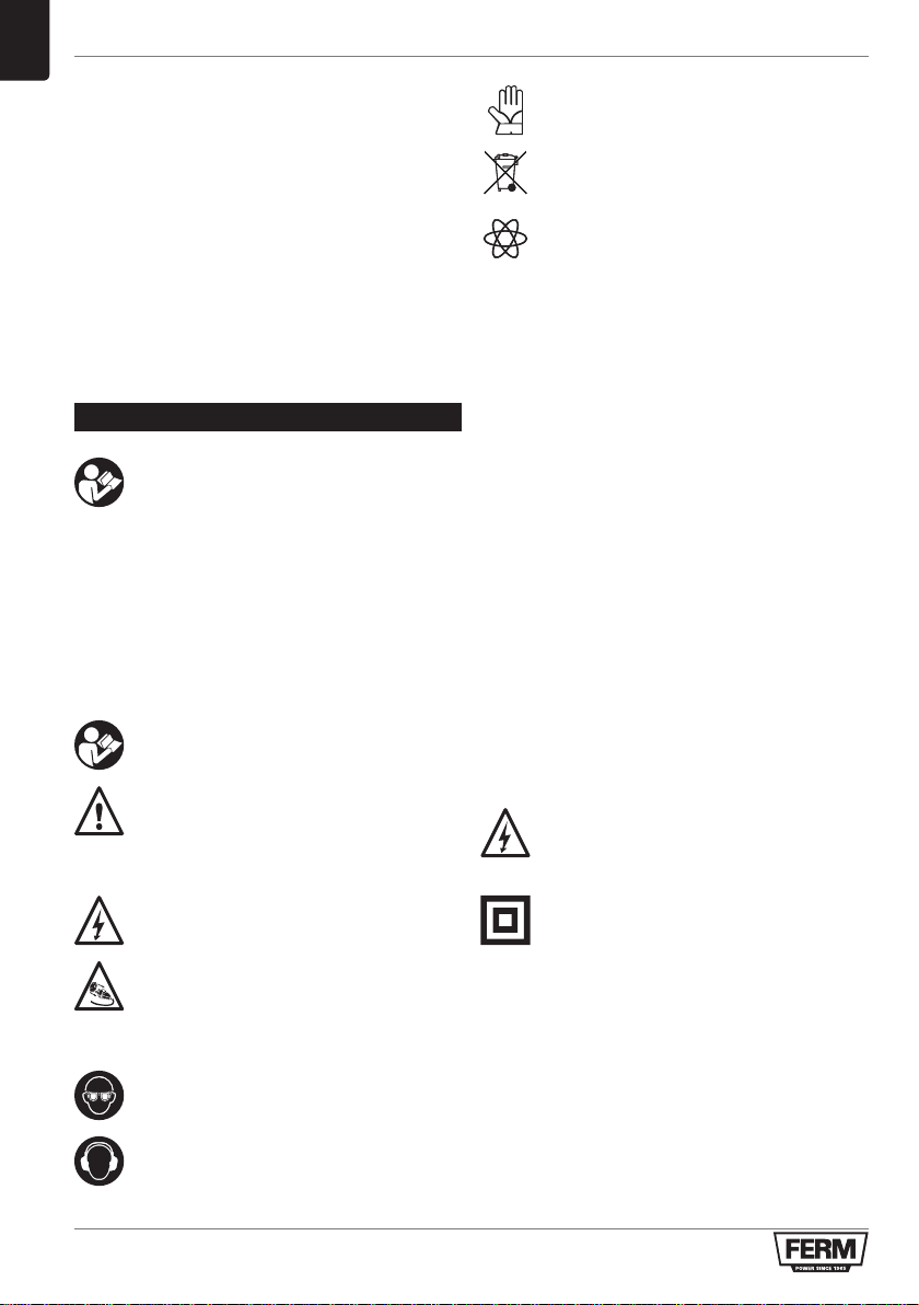
The following symbols are used in the user
manual or on the product:
Read the user manual.
Denotes risk of personal injury, loss of life
or damage to the tool in case of nonobservance of the instructions in this
manual.
Wear safety gloves.
Do not dispose of the product in
unsuitable containers.
Variable electronic speed
Additional safety warnings for rotary
hammers
a) Wear ear protectors. Exposure to noise can
cause hearing loss.
b) Use auxiliary handle(s), if supplied with the
tool. Loss of control can cause personal injury.
c) Hold power tool by insulated gripping
surfaces, when performing an operation
where the cutting accessory may contact
hidden wiring or its own cord. Cutting
accessory contacting a “live” wire may make
exposed metal parts of the power tool “live”
and could give the operator an electric shock.
Electrical safety
When using electric machines always observe the
safety regulations applicable in your country to
reduce the risk of fire, electric shock and personal
injury. Read the following safety instructions and
also the enclosed safety instructions.
Always check that the voltage of the
power supply corresponds to the voltage
on the rating plate label.
Risk of electric shock
Immediately remove the mains plug from
the mains if the mains cable becomes
damaged and during cleaning and
maintenance.
Always wear eye protection!
Wear hearing protection.
If operating a power tool in a damp location is
unavoidable, use a residual current device (RCD)
protected supply. Use of an RCD reduces the risk
of electric shock.
Replacement of power cords or plugs
If the supply cord is damaged, it must be replaced
by the manufacturer, its service agent or similarly
qualified persons in order to avoid a hazard.
Class II machine - Double insulation - You
don’t need any earthed plug.
4
Page 5

EN
Mains plug replacement (UK only)
If the moulded 3-pin plug attached to the unit is
damaged and needs replacing, it is important
that it is correctly destroyed and replaced by
an approved BS1363/13A fused plug and that
the following wiring instructions are followed.
The wires in the mains cable are coloured in
accordance with the following code:
• blue neutral
• brown live
As the colours of the wires in the mains cable
of the unit may not correspond to the coloured
markings identifying the terminals in the plug,
proceed as follows:
• The wire which is coloured blue must be
connected to the terminal which is marked
with the letter N or coloured black.
• The wire which is coloured brown must be
connected to the terminal which is marked
with the letter L or coloured red.
Use of extension leads
Only ever use approved extension leads that are
suitable for the power rating of the machine. The
minimum core thickness is 1.5 mm2. Whenever
using a reel extension lead, always fully unroll the
lead.
Immediately switch off the machine when:
• Excessive sparking of the carbon brushes.
• Interruption of the mains plug, mains lead or
mains lead damage.
• Defect switch.
• Smoke or stench of scorched isolation.
2. MACHINE INFORMATION
Intended use
This rotary hammer is intended for drilling holes
in masonry such as brick, concrete and similar
material. Furthermore, the machine can be used
as a demolition hammer in combination with the
SDS cold chisels provided. The machine is on no
account intended for other purposes.
Not suitable for construction site usage
Technical specifications HDM1030P
Mains voltage 230-240 V ~
Mains frequency 50 Hz
Power input 850 W
No-load speed 0-1250 /min
Max. Drill diameter
-Concrete
-Steel
-Wood
Weight 3.3kg
Protect yourself against the effects of vibration by
maintaining the tool and its accessories, keeping
your hands warm and organizing your work
patterns.
Ø 26 mm
Ø 13 mm
Ø 30 mm
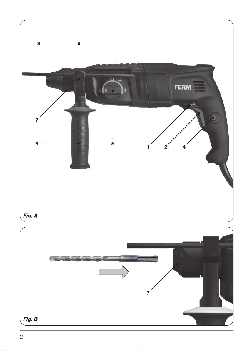
Description
The numbers in the text refer to the diagrams on
pages 2-3
Fig. A
1. Left/right rotation switch
2. On/Off switch
4. Lock-on button
5. Function selection switch
6. Side handle
7. Locking sleeve
8. Depth stop ruler
9. Depth stop button
3. OPERATING
Hammer drills require very little operator
pressure. Excessive pressure on the tool
can lead to unnecessary overheating of
the motor, and burning of the driven tool.
It also may happen the drill bit deforms
and cannot be removed from the
machine again.
Side handle
Fig. A
The side handle (6) can be rotated 360° around
the drill head, enabling safe and comfortable
operation for both left and right-handed users.
5
Page 6

EN
• Loosen the handgrip by turning it
anticlockwise.
• Rotate the handgrip to the desired position.
• Retighten the handgrip in the new position by
turning it clockwise.
Exchanging and removing drill bits
Fig. A - B
Before exchanging bits, first remove the
power plug from the wall socket.
Inspect bits regularly during use. Blunt
bits should be re-sharpened or replaced.
Lightly oil the bit shaft before inserting it
into the chuck.
• SDS drills can be inserted by pushing the drill
into the chuck until a click can be heard. If
needed rotate the SDS drill a little to ensure the
keyway in the bit fits the chuck well.
DO NOT slide the locking sleeve (7) to the
rear when inserting bits.
• To remove the SDS drill, slide the locking
sleeve (7) to the rear and remove the SDS drill
while keeping the sleeve (7) in this position.
Setting depth stop
Fig. A
• The depth stop ruler can be added to the side
handle by pushing the dept stop button (9).
• Keep pushing the depth stop button (9) and
insert the depth stop ruler (8) through the hole
on the side handle ring.
• Slide the ruler to the desired depth.
• Loosen the depth stop button (9).
The On/Off switch
Fig. A
• Switch the machine on by pressing the On/Off
switch (2). When releasing the On/Off switch
(2) the machine will turn off.
• The rotation-speed can be continuously
adjusted by pressing the On/Off switch (2)
deeper or less deep.
Lock-on button
Fig. A
• Lock the On/Off switch (2) by pressing the On/
Off switch (2) and then pressing the lock-on
button (4).
• Release the switch-lock by shortly pressing
the On/Off switch (2) again.
Switching the direction of rotation
Fig. A.
• Direction of rotation counter-clockwise: shift
left/right switch (1) to “
• Direction of rotation clockwise: shift left/right
switch (1) to “ ”.
This function is only available when the machine
is set to “drill mode” (As shown in fig. D function
A & B).
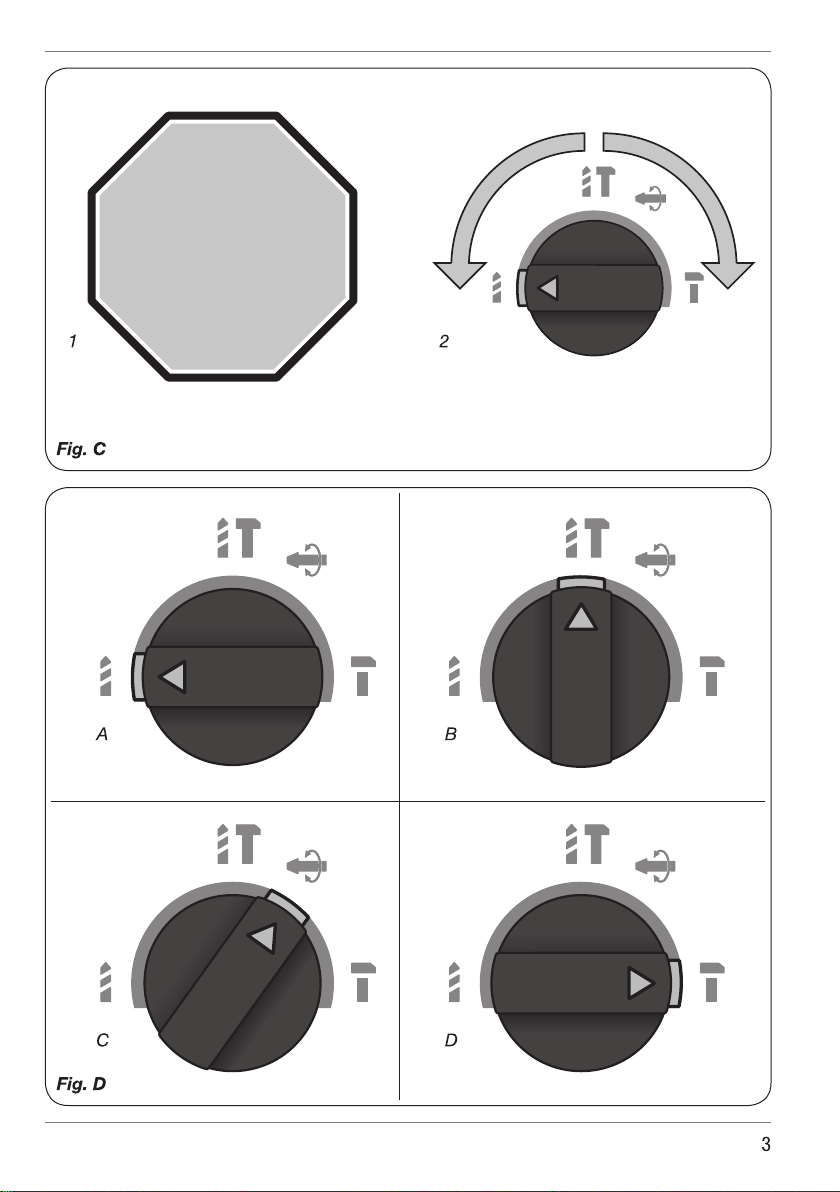
Function selection switch
In order to avoid damage to the machine,
adjusting the function selection switch (5)
shall only be done when machine is not
running. Fig. C
Fig. D
The correct position of the function selection
switch (5) for each function is shown in the
pictures in fig. D. Always make sure the function
switch clicks in the desired position.
A) Drilling (without hammer function): for drilling
in several materials.
B) Hammer Drilling (with hammer function): for
drilling in masonry such as brick, concrete and
similar material.
C) Chisel angle adjustment: for changing the
angle of the chisel. When set under right angle
switch back to position D. before using the
tool.
D) Chipping (chisel function): for chipping and
small demolition jobs.
User tips
Always use the machine with the side handle
firmly anchored in place - you will not only work
with more comfort, you will also work with more
precision.
Caution: drills and chisels can get very
hot.
”.
6
Page 7

EN
Drilling and hammer drilling (function A and B)
• For large holes, for instance in very hard
concrete, start using a smaller bit for pilot
drilling first, then drill to nominal size.
• Hold the machine firmly with 2 hands. Be
aware the drill can jam and because of that
machine might suddenly turn (especially when
drilling deep holes).
• Do not apply a lot of pressure on the machine,
let the machine do the work.
Chipping in concrete and brick (function C & D)
• It’s also possible to use the machine for
chipping.
• Only change the function when the motor has
come to a standstill.
• Do not apply a lot of pressure on the machine,
let the machine do the work.
4. MAINTENANCE
Before cleaning and maintenance, always
switch off the machine and remove the
mains plug from the mains.
Clean the machine casings regularly with a soft
cloth, preferably after each use. Make sure that
the ventilation openings are free of dust and
dirt. Remove very persistent dirt using a soft
cloth moistened with soapsuds. Do not use any
solvents such as gasoline, alcohol, ammonia
etc. Chemicals such as these will damage the
synthetic components.
WARRANTY
The warranty conditions can be found on the
separately enclosed warranty card.
ENVIRONMENT
Faulty and/or discarded electrical or
electronic apparatus have to be collected
at the appropriate recycling locations.
Only for EC countries
Do not dispose of power tools into domestic
waste. According to the European Guideline
2012/19/EC for Waste Electrical and Electronic
Equipment and its implementation into national
right, power tools that are no longer usable must
be collected separately and disposed of in an
environmentally friendly way.
The product and the user manual are subject
to change. Specifications can be changed
without further notice.
Defects
The machine should be regularly inspected for
the following possible defects and repaired if
necessary.
• Damage to power cord.
• Broken on/off trigger assembly.
• Short circuiting.
• Damaged moving parts.
Faults
Should a fault occur, e.g. after wear of a part,
please contact your seller or the service address
on the warranty card. Separate you find an
exploded view showing the parts that can be
ordered.
7
Page 8

Spare parts list
HDM1030P
No Description Position
471023 Front sleeve complete 1-9
471000 Steel ball 7.125 7
471001 Chisel lock plate complete 10-12
840709 Needle bearings 0709 12
471002 Front bearing complete 13-15
843012 Needle bearings 3012 14
471003 Selector knob complete 17-21
471004 Drive sleeve complete 23-33
471005 O ring 21.5*1.8 30
471006 Impact hammer set 34-37
471007 O ring 16.2*4.5 38
471008 O ring 10*3 39
471009 Piston complete 38-44
471010 O ring 15.2*3 43
471011 Excentric gear set 45-51, 53, 58
471012 O ring 23.5*2.4 53
471013 Needle bearings K5 57
471014 Excentral rod bearing 58
840912 Needle bearings 0912 59
471015 Selector sleeve 59-63
471016 Bearing 699-K (20*9*5) 62
471024 Capacitor 65
471017 Brush holder (2pcs) 66
471018 Carbon brush (2 pcs) 67
471019 Switch 68
471020 Stator 78
830607 Bearing 607-2RS 81
471021 Rotor assembly 81-86
830609 Bearing 609-RS 85
471022 Side handle complete 87-91, 93
8
Page 9

Exploded view
9
Page 10

10
Page 11

11
Page 12

1504-24
www.ferm.com ©2015 FERm B.V.
 Loading...