

Page 1
Ferm b.v. • P.O. Box 134 • 8280 AC Genemuiden NL • Web: www.ferm.com 0107/13-1
Art.nr. 326110
FBF-6E
USERS MANUAL
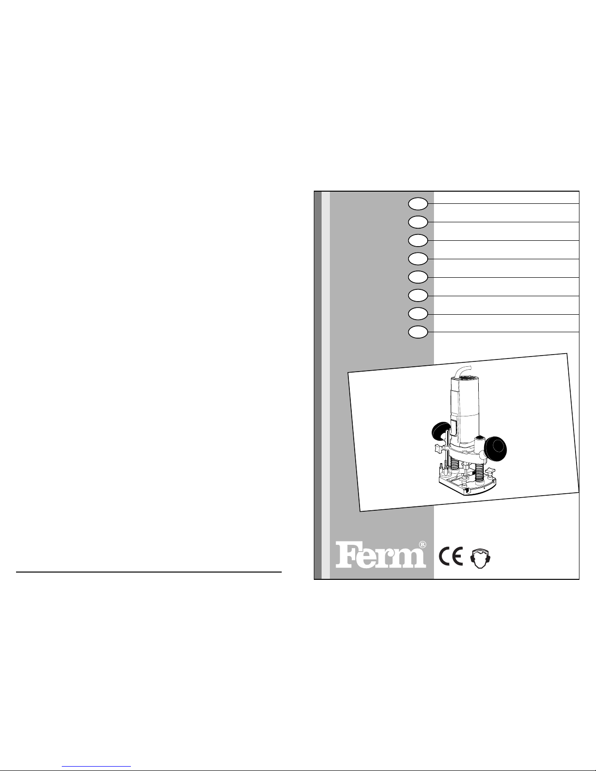
Router 02
GEBRAUCHSANWEISUNG
Oberfräse 07
GEBRUIKSAANWIJZING
Bovenfrees 13
MODE D’EMPLOI
Défonceuse 18
BRUKSANVISNING
Överfräs 24
KÄYTTÖOHJE
Yläjyrsin 29
BRUKSANVISNING
Overfres 34
BRUGER VEJLEDNING
Overfladefræser 40
GB
D
NL
F
SV
SU
N
DK
UK Subject to change
D Änderungen vorbehalten
NL Wijzigingen voorbehouden
F Sous réserve de modifications
SV Ändringar förbehålles
SU Pidätämme oikeuden muutoksiin
NO Rett till endringer forbeholdes
DK Ret til ændringer forbeholdes
Page 2
Ferm 39
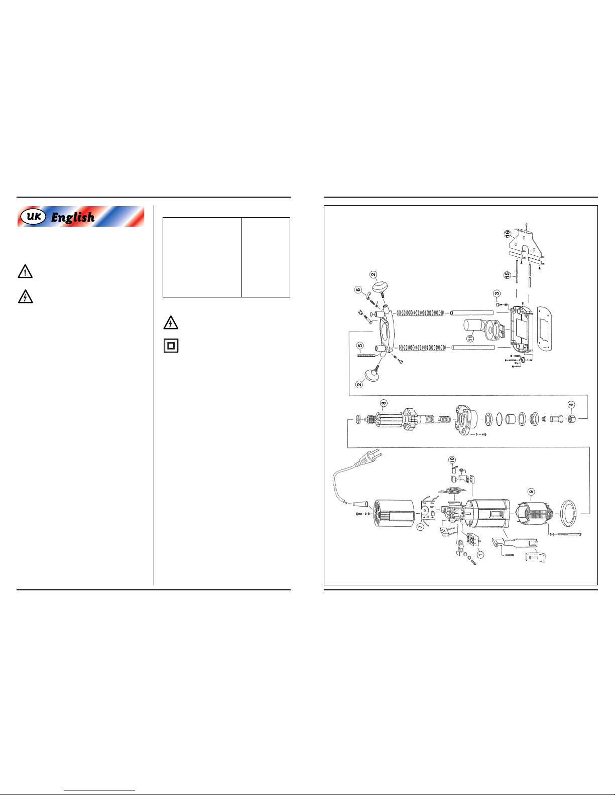
EEXXPPLLOODDEEDD VVIIEEWW
ROUTER
The following symbols are used throughout this manual:
Denotes risk of personal injury, loss of life or
damage to the tool in case of non-observance of
the instructions in this manual.
Denotes risk of electric shock.
Carefully read this manual before using the machine.
Make sure that you know how the machine functions and
how to operate it. Maintain the machine in accordance
with the instructions to make sure it functions properly.
Keep this manual and the enclosed documentation with
the machine.
SAFETY INSTRUCTIONS
When using electric machines always observe the
safety regulations applicable in your country to
reduce the risk of fire, electric shock and personal
injury. Read the following safety instructions and also
the enclosed safety instructions.
Keep these instructions in a safe place!
• Check workpieces for any protruding nails etc. and
remove these.
• Keep your hands away from the surface to be cut.
TECHNICAL SPECIFICATIONS
Voltage 230 V~
Frequency 50 Hz
Power input 550 W
No load speed 8000–32000/min
Max. cutter diameter 30 mm
Cutting depth 35 mm
Collet 6 mm
Weight 3.25 kg
Lpa(sound pressure) 81.3 dB(A)
Lwa(sound power) 94.3 dB(A)
Vibration value < 4.0 m/s
2
Fuses 230 V machines 10 A
Electrical safety
Always check that the power supply corresponds to the voltage on the rating plate.
Your machine is double insulated in accordance
with EN 50144; therefore no earthwire is required.
Replacing cables or plugs
Immediately throw away old cables or plugs when they
have been replaced by new ones. It is dangerous to insert
the plug of a loose cable in the wall outlet.
Using extension cables
Only use an approved extension cable suitable for the
power input of the machine. The minimum conductor size
is 1.5 mm
2
. When using a cable reel always unwind the
reel completely.
PACKAGE CONTENTS
1 router
1 cutter
1 parallel guide
2 screws
1 6 mm collet (1/4”)
1 8 mm collet
2 open-ended spanners
1 hexagonal key
1 instruction manual
1 safety instructions
1 guarantee card
Check the machine, loose parts and accessories for transport damage.
2 Ferm
Page 3
38 Ferm
SPARE PARTS LIST FBE-6E
REF.NR. DESCRIPTION FERM NR.
001 SWITCH 302008
002 HANDLE 302003
003 LOCKING BOLT 302002
004 COLLET NUT 312009
005 CUTTING DEPTH STOP 302009
006 CLAMPING LEVER 302010
007 ELECTRONIC SPEED CONTROL 302011
008 ROTOR 302012
009 STATOR 302013
010 CARBON BRUSH (SET) 302014
011 DUSTEXTRACTING ADAPTOR 302015
015 GUIDE ROD 302005
016 GUIDE FRAME 302006
- OPEN ENDED SPANNER 302016
- OPEN ENDED SPANNER (COLLET NUT) 312011
- SPRING COLLET 6 MM 312012
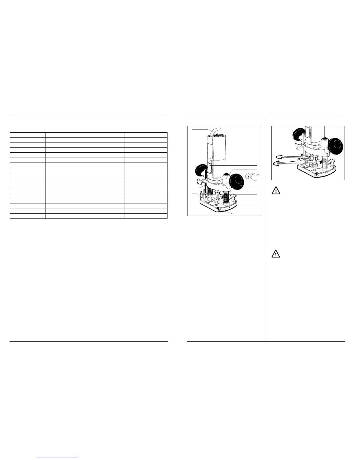
PRODUCT INFORMATION
Fig. A.
This machine has been designed for professional routing
of wood, wood products and plastics.
1 on/off switch
2 machine clamp screw
3 clamping lever for depth adjustment
4 handle
5. collet bracket
6 collet nut
7 router base
8 opening for parallel guide
9 locking bolt for parallel guide
10 revolver-depth stop
11 scale cutting depth
12 locking bolt depth stop
13 adjusting wheel electronic speed control
MOUNTING ACCESSORIES
Fig. B.
Prior to mounting an accessory always unplug
the tool.
Mounting and removing cutters.
Only use cutters with a shaft diameter which corresponds
with the size of the collet. Only use cutters which are suited
for the maximum speed of the machine. The cutter diameter should not exceed the maximum diameter (see ‘Technical specifications’).
• Place an open-ended spanner on the collet bracket
and use the second spanner to loosen the collet nut.
• Place the cutter shaft in the collet.
• Tighten the collet nut so that the cutter is locked properly.
• Open the collet nut when you want to replace a cutter.
Wait until the machine has come to a complete
standstill and the cutter has cooled down before
replacing a cutter.
1
4
5
6
7
8
9
10
11
12
13
3
2
Ferm 3
Page 4
Ferm 37
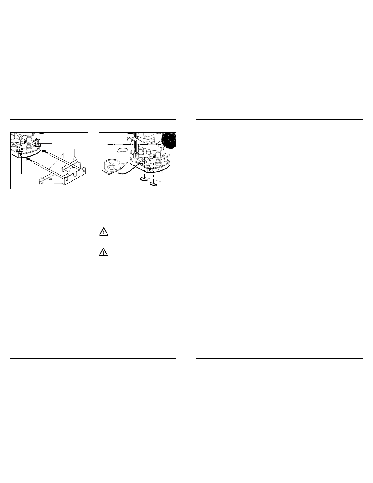
Mounting and adjusting the parallel guide
Fig. C
The parallel guide is a handy aid when working on narrow
workpieces.
• Mount the parallel guide. Attach the guide rods (15) on
the frame (14) using the bolts (16).
• Loosen the locking bolts (9) and slide the guide rods in
the openings (8).
• Adjust the parallel guide to the desired guide distance.
• Tighten the locking bolts again.
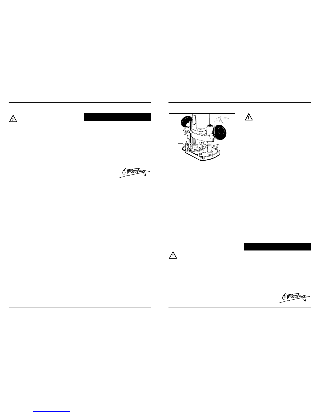
Mounting the adapter for dust extraction.
Fig. D
Use the adapter for extracting dust.
• Loosen the machine clamp screw (2) and remove the
machine from its base.
• Mount the adapter for dust extraction (18) on the router
base (7) using the screws (17) and nuts (19).
• Replace the maschine into the base.
• Place a vacuum cleaner nozzle on the adapter outlet.
Keep the outlet of the machine behind the
machine for a good view on the workpiece.
OPERATION
Always observe the safety instructions and
applicable regulations.
Hold the machine in rest position on the workpiece when
switching the machine on or off. The cutter in the collet
may damage the workpiece.
• Clamp the workpiece and make sure that the workpiece cannot slide from under the machine during the
cutting activities.
• Hold the machine firmly and move it evenly over the
workpiece. Do not force the machine.
• Only use cutters which do not show any signs of wear.
Worn cutters have a negative effect on the efficiency of
the machine.
• Always switch off the machine first before removing
the plug from the wall socket.
18
2
19
17
7
9 8 14
9
8
15
16
4 Ferm
Page 5
VEDLIGEHOLDELSE
Sørg for at maskinen ikke står under strøm, når
der udføres vedligeholdelsesarbejder på meka-
nikken.
Maskinerne fra Ferm er udviklet til at fungere lœnge
uden problemer med et minimum af vedligeholdelse. Ved at rengøre maskinen regelmœssigt og
behandle den korrekt, bidrager De til en lœngere
levetid for maskinen.
Rengøring
Rengør regelmœssigt maskinkappen med en blød klud,
helst efter hvert brug. Sørg for at ventilationshullerne er fri
for støv og snavs.
Brug en blød klud, der er vœdet i sœbevand til at fjerne
hårdnakket snavs. Brug ingen opløsningsmidler, så som
benzin, alkohol, ammoniak, osv. Den slags stoffer beskadiger kunststofdelene.
Smøring
Maskinen behøver ingen ekstra smøring.
Fejl
Kontakt Deres Ferm-forhandler, hvis der opstår fejl som
følge af slitage af en del.
Bagerst i denne brugsanvisning finder De en reservedelstegning med de reservedele, der kan bestilles.
MILJØ
For at undgå transportbeskadigelse leveres maskinen i
en solid emballage. Emballagen er så vidt muligt lavet af
genbrugsmateriale. Genbrug derfor emballagen.
Når de udskifter Deres maskinen bør De tage den gamle
maskine med til Deres lokale Ferm-forhandler. Der vil
maskinen blive bearbejdet på miljøvenlig vis.
GARANTI
Lœs det separat vedlagte garantikort for garantibetingelserne.
ClEl
■
KONFORMITETSERKLÆRING
(DK)
Vi erklærer at under almindeligt ansvar, at dette
produkt er i overenstemmelse med følgende
normer eller normative dokumenter
EN50144-1, EN50144-2-17,
EN55014-1, EN55014-2,
EN61000-3-2, EN61000-3-3
i henhold til bestemmelserne i direktiverne:
98/37EEC
73/23EEC
89/336EEC
01-11-1999
GENEMUIDEN NL
G.M. Ensing
Quality department
36 Ferm
Adjusting the cutting depth
Fig. E
The cutting depth can be adjusted in two ways.
Adjustment using the scale
• Loosen the locking bolt of the depth stop (12).
• Release clamping lever (3) and press the machine so
far down until the cutter touches the workpiece.
• Tighten the clamping lever again.
• Set the desired cutting depth using the graduated scales (11) and then tighten the clamp screw.
Adjustment using the revolver- depth stop
The revolver-depth stop enables you to quickly choose
between three different cutting depths. These are also
determined by the adjustment of the depth scale (11).
• Adjust the required cutting depth by the three screws
on the revolver-depth stop (10).
Switching on and off (Fig. A).
• Depress the on/off switch (1) to switch the machine on.
Then push the switch through its resistance to lock the
switch in the on position. The cutter speed can be
adjusted by means of the adjusting wheel (13).
• Release the on/off switch to switch the machine off or
push the switch again when it is in locked position.
Always select a low speed for cutting plastic
workpieces.
Do not put the machine down when the motor is still running. Do not place the machine on a dusty surface. Dust
particles may enter the mechanism.
MAINTENANCE
Make sure that the machine is not live when carrying out maintenance work on the motor.
The Ferm machines have been designed to operate over
a long period of time with a minimum of maintenance. Continuous satisfactory operation depends upon proper
machine care and regular cleaning.
Cleaning
Regularly clean the machine housing with a soft cloth, preferably after each use. Keep the ventilation slots free from
dust and dirt.
If the dirt does not come off use a soft cloth moistened with
soapy water. Never use solvents such as petrol, alcohol,
ammonia water, etc. These solvents may damage the
plastic parts.
Lubrication
The machine requires no additional lubrication.
Faults
Should a fault occur, e.g. after wear of a part, please contact your local Ferm dealer.
In the back of this manual you find an exploded view
showing the parts that can be ordered.
ENVIRONMENT
In order to prevent the machine from damage during transport, it is delivered in a sturdy packaging. Most of the packaging materials can be recycled. Take these materials to
the appropriate recycling locations.
Take your unwanted machines to your local Ferm-dealer.
Here they will be disposed of in an environmentally safe
way.
GUARANTEE
The guarantee conditions can be found on the separately
enclosed guarantee card.
ClEl
■
DECLARATION OF CONFORMITY
(GB)
We declare under our sole responsability that this
product is in conformity with the following
standards or standardized documents
EN55014-1, EN55014-2
EN50144-1, EN50144-2-17,
EN61000-3-2, EN61000-3-3,
in accordance with the regulations.
98/37EEC, 73/23EEC, 89/336EEC
from 01-11-1999
GENEMUIDEN NL
G.M. Ensing
Quality department
10
11
12
3
Ferm 5
Page 6
Montage af adapteren til sugning af støv.
Fig. D.
Anvend adapteren til afførelse af støv.
• Løsn klemskruen (2) foran maskinen og tag maskinen
ud af fundamentet.
• Montér adapteren til sugning af stof (18) ved hjœlp af
skruerne (17) og møtrikkerne (19) på frœsesålen (7).
• Montér maskinen på fundamentet
• Sæt støvsugerens mundstykke på adapterens
udgang.mundstykket fra en støv suger på adapterens
munding.
Hold adapterens munding bag maskinen for at
have et godt syn på arbejdsstykket.
BETJENING
Følg altid sikkerhedsinstruktionerne og hold
Dem til de gœldende forskrifter.
Hold maskinen stille på arbejdsstyk ket, når De tœnder
eller slukker maskinen. Frœsebitten i klamperen kan beskadige arbejdsstykket.
• Klem stykket fast eller sørg på an den måde for, at det
under arbejdet ikke kan glide vœk under maskinen.
• Hold maskinen godt fast og bevœg denne regelmœssigt hen over arbejdet. Forcér ikke maskinen.
• Anvend udelukkende frœsebits, som endnu ikke har
vist tegn på slitage. Slidte frœsebits kan have en negativ indflydelse på maskinens effektivitet.
• Sluk altid først maskinen efter endt arbejde, før De
trœkker stikket ud af stikkontakten.
Indstilling af frœsedybde
Fig. E.
Maskinen har to muligheder til at indstille frœsedybden.
Indstilling ved hjœlp af gradfordeling
• Skru klemskruen løs fra dybdebe lœgningen (12).
• Sœt klemhåndtaget (3) fri, og tryk maskinen så vidt
som muligt nedad, så frœsebitten rører arbejdet.
• Sœt klemhåndtaget fast igen.
• Ved hjælp af skalainddelingen (11) indstilles den ønskede fræsedybde, og klemskruen strammes til.
Indstilling ved hjœlp af gradfordeling
Ved hjælp af revolver-dybdeanslaget kan der hurtigt vælges mellem tre forskellige fræsedybder. Disse bestemmes blandt andet af dybdeanslagets indstilling (11).
• Indstil ved hjœlp af de tre skruer på revolver-dybdebelœgningen (10) de ønskede frœsedybder.
Tœnde og slukke (Fig. A)
• Tryk afbryderen (1) ned for at starte maskinen. Ved at
trykke afbryderen over modstanden og trykke den ind,
kan den blokeres i denne position. Fræsehastigheden
reguleres ved hjælp af justeringshjulet (13).
• Maskinen slukkes ved at slippe afbryderen, eller den
trykkes igen ind, hvis den er i blokeret position.
Indstil altid et lavt antal omdrej ninger ved frœsning af arbejdsstykker i kunststof.
Sœt maskinen først vœk, når motoren er fuldstœndig
slukket. Sœt aldrig maskinen på en støvet undergrund,
idet støvdele kan trœnge ind til mekanikken.
10
11
12
3
18
2
19
17
7
Ferm 35
FBF-6E OBERFRÄSE
In dieser Betriebsanleitung erscheinen folgende Piktogramme:
Verweist auf Verletzungsgefahr, Gefahr für
Leben und mögliche Beschädigung der
Maschine, falls die Anweisungen in dieser Betriebsanleitung nicht befolgt werden.
Deutet das Vorhandensein elektrischer Span-
nung an.
Lesen Sie diese Betriebsanleitung aufmerksam, bevor
Sie die Maschine in Betrieb nehmen. Machen Sie sich vertraut mit der Funktionsweise und der Bedienung. Warten
Sie die Maschine entsprechend den Anweisungen, damit
sie immer einwandfrei funktioniert. Die Betriebsanleitung
und die dazugehörende Dokumentation müssen in der
Nähe der Maschine aufbewahrt werden.
SICHERHEITSVORSCHRIFTEN
Beachten beim Benutzen von Elek tromaschinen immer
die örtlichen Sicherheitsvorschriften bezüglich Feuerrisiko, Elektroschock und Verletzung. Lesen Sie außer den
folgenden Hinweisen ebenfalls die Sicherheitsvorschriften im einschlägigen Sonderteil.
Die Hinweise müssen sicher aufbewahrt werden!
• Überprüfen Sie Werkstücke auf absagende Nagel
u.ä. und entfernen Sie sie.
• Halten Sie Ihre Hände von der Fräsfläche fern.
TECHNISCHE DATEN
Spannung 230 V~
Frequenz 50 Hz
Aufgenommene Leistung 550 W
Drehzahl unbelastet 8000–32000/min
1
Max. Fräserdurchmesser 30 mm
Frästiefe 35 mm
Spannfutter 6 mm
Gewicht 3.25 kg
Lpa(Schalldruck) 81.3 dB(A)
LWA (Schalleistung) 940.3 dB(A)
Vibrationswert < 4.0 m/s
2
Sicherungen 230 V-Maschinen 10 A
Elektrische Sicherheit
Überprüfen Sie immer, ob Ihre Netzspannung
der des Typenschilds entspricht.
Die Maschine ist nach EN 50144 doppelisoliert;
daher ist Erdung nicht erforderlich.
Austauschen von Kabeln oder Steckern
Entsorgen Sie alte Kabel oder Stecker, unmittelbar nachdem Sie durch neue ersetzt sind. Das Anschließen eines
Steckers eines losen Kabels an eine Steckdose ist gefährlich.
Verwendung von Verlängerungskabeln
Benutzen Sie nur ein genehmigtes Verlängerungskabel,
das der Maschinenleistung entspricht. Die Ader müssen
einen Mindestquerschnitt von 1,5 mm
2
haben. Befindet
das Kabel sich auf einem Haspel. muß es völlig abgerollt
werden.
INHALT DER VERPACKUNG
1 Oberfräse
1 Fräser
1 Parallelführung
2 Schrauben
1 Adapter für Staubabsaugung
1 Spannzange 6 mm (1/4")
1 Spannzange 8 mm
2 Steckschlüssel
1 Sechskantschlussel
1 Betriebsanleitung
1 Sicherheitsheft
1 Garantiekarte
Überprüfen Sie die Maschine, lose Teile und Zubehör auf
Transportschäden.
6 Ferm
Page 7

MONTAGE AF TILBEHØR
Fig. B.
Tag altid stikket ud af kontakten før montage.
Placering og fjernelse af frœsebits
Anvend frœsebits med en skaftdiameter, som er i overensstemmelse med klamperens størrelse. Anvend udelukkende frœsebits, som er egnede til maskinens max.
antal omdrejninger. Frœsediameteren må ikke overskride den max. diameter (se ‘Tekniske specifikationer’).
• Sæt gaffelnøglen på spændetangholderen og løsn
spændetangmøtrikken med den anden gaffelnøgle.
• Drej klampermøtrikken åbn ved hjœlp af gaffelnøglen.
• Placér frœsebittens skaft i klampe rens optagelse.
• Drej klampermøtrikken på, så frœsebitten sidder godt
fast.
• Drej klampermøtrikken åben igen, når De vil skifte
frœsebitten.
Vent med at udskifte frœsere under arbejdet,
indtil maskinen står helt stille, og frœseren er
afkølet.
Montage og indstilling af parallellederen
Fig. C.
Parallellederen er egnet som hjœl pemiddel ved frœsning
af et smalt arbejdsstykke.
• Parallellederen er egnet som hjœl pemiddel ved frœsning af et smalt arbejdsstykke.
• Saml parallellederen. Fastgør lederstœngerne (15)
på rammen (14) ved hjœlp af boltene (16).
• Drej klemskruerne (9) løs og skub lederstœngerne i
optagelserne (8).
• Indstil parallellederen på den ønskede ledningsafstand.
• Skru klemskruerne fast igen.
9 8 14
9
8
15
16
34 Ferm
PRODUKTINFORMATION
Abb. A.
Die Maschine eignet sich für professionelle Fräsarbeiten
in Holz, holzähnlichen Materialien und Kunststoffen.
1 Ein-Aus-Schalter
2 Klemmschraube für Maschine
3 Klemmhebel für Tiefeneinstellung
4 Griff
5 Spannzangenhalter
6 Spannzangenmutter
7 Frässohle
8 Aufnahme für Parallelführung
9 Klemmschraube für Parallelführung
10 Revolver-Tiefenanschlag
11 Verteilung der Frästiefe
12 Klemmschraube Tiefenanschlag
13 Verstellrad elektronische Drehzahlregelung
MONTAGE DES ZUBEHÖRS
Abb. B
Ziehen Sie immer den Netz stecker, bevor Sie
mit der Arbeit anfangen.
Montieren und Entfernen der Fräser.
Montieren Sie Fräser mit einem Schaftdurchmesser, der
dem Spannfutter entspricht. Benutzen Sie nur Fräser, die
für die Höchstdrehzahl der Maschine geeignet sind. Der
Fräserdurchmesser darf den größten Durchmesser nicht
überschreiten (siehe Technische Daten).
• Setzen Sie einen Steckschlüssel auf den Spannzangenhalter und lösen Sie mit dem zweiten Steckschlüssel die Spannzangenmutter.
•
Stecken Sie die Schaft des Fräsers in die Spannfutteraufnahme.
•
Ziehen Sie die Spannfuttermutter an, bis der Fräser gut fest sitzt.
•
Zum Wechseln des Fräsers öffnen Sie die
Spannfuttermutter.
Warten Sie mit dem Austausch der Fräser, bis
die Maschine völlig stillsteht und der Fräser
abgekühlt ist.
1
4
5
6
7
8
9
10
11
12
13
3
2
Ferm 7
Page 8

TEKNISKE SPECIFIKATIONER
Spœnding 230 V~
Frekvens 50 Hz
Optaget effekt 550 W
Omdrejninger, ubelastet 8000-32000/min
Max. frœsediameter 30 mm
Frœsedybde 35 mm
Klamper 6 mm
Vœgt 3.25 kg
Lpa(lydtryk) 81.3 dB(A)
Lwa(lydeffekt) 94.3 dB(A)
Vibrationsvœrdi > 4.0 m/s
2
Sikringer 230 V maskiner 10 A
Elektrisk sikkerhed
Kontroller altid om netspœndingen svarer til
vœrdien på typeskiltet.
Maskinen er dobbeltisoleret i henhold til EN
50144; det er derfor ikke nødvendigt med en
jordledning.
Ved udskiftning af ledninger og stik
Kasser gamle ledninger og stik, så snart de er skiftet ud
med nye. Det er farligt at sœtte et stik fra en løs ledning i en
stikkontakt.
Ved brug af forlœngerledninger
Brug udelukkende godkendte forlœn gerledninger, der er
beregnede til maskinens effekt. Lederne skal have et gennemsnit på mindst 1,5 mm
2
. Hvis forlœngerledningen sid-
der på en tromle, rulles ledningen helt af.
EMBALLAGENS INDHOLD
1 overfladefrœser
1 frœsebit
1 parallelleder
2 skruer
1 adapter til at suge støv
2 gaffelnøgle
1 unbrakonøgle
1 spændetang 6 mm (1/4”)
1 spændetang 8 mm
1 brugsanvisning
1 sikkerhedsfolder
1 garantikort
Kontroller maskinen, løsdele og tilbehør for transportskade.
PRODUKTINFORMATION
Fig. A.
Overfladefrœseren er egnet til professionelt frœsearbejde i trœ og trœlignende materialer samt i kunststoffer.
1 tœnd/sluk-kontakt
2 klemskrue til maskine
3 klemgreb til dybdeindstilling
4 håndgreb
5 spændetangholder
6 spændetangmøtrik
7 frœsesål
8 optagelse til parallelleder
9 klemskrue til parallelleder
10 revolver-dybdebelœgning
11 gradinddeling frœsedybde
12 klemskrue dybdebelœgning
13 stelhjul elektronisk hastighedsregulering
1
4
5
6
7
8
9
10
11
12
13
3
2
Ferm 33
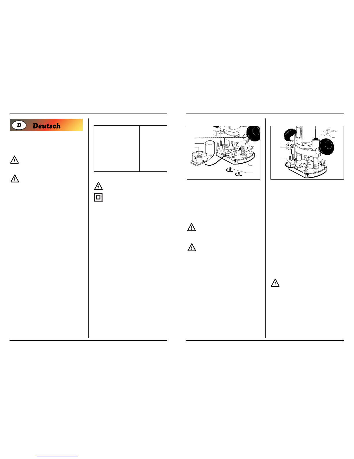
Montieren und einstellen der Parallelführung
Abb. C
Die Parallelführung ist ein Hilfsmittel beim Fräsen von
schmalen Werkstücken.
• Bauen Sie die Parallelführung zu sammen. Befestigen Sie mit Hilfe der Schrauben (16) die Führungsstangen (15) auf den Rahmen (14).
• Lös en Sie die Klemmschrauben (9) und schieben Sie
die Führungsstangen in die Aufnahmen (8).
• Stellen Sie die Parallelführung auf die gewünschte
Führungsabstand ein.
• Ziehen Sie die Klemmschrauben wieder fest.
Montieren des Staubsaug adapters
Abb. D
Benutzen Sie den Adapter zum Absaugen von anfallendem Staub
• Lösen Sie die Klemmschraube (2) für die Maschine
und entfernen Sie die Maschine aus der Halterung.
• Montieren Sie den Staubabsaug adapter (18) mit Hilfe
der Schrauben (17) und Muttern (19) auf die Frässohle
(7).
• Montieren Sie die Maschine zuruck in der Halterung.
• Setzen Sie das Mudstück eines Staubsaugers auf den
Ausgang des Adapters.
Halten Sie zwecks einer guten Sicht auf dem
Werkstück, den Auslauf des Adapters hinter der
Maschine.
BEDIENUNG
Beachten Sie immer die Sicher heitshinweise
und halten Sie sich an die einschlägigen Vor-
schriften.
Halten Sie die Maschine in Ruhestellung auf das
Werkstück, wenn Sie die Maschine ein- bzw. ausschalten.
Der Fräser im Spannfutter könnte das Werkstück beschädigen.
• Klemmen Sie das Werkstück ein oder sichern Sie es
auf eine andere Weise, damit es während der Arbeit
nicht verrutscht.
• Halten Sie die Maschine sicher und bewegen Sie sie
gleichmäßig über das Werkstück. Forcieren Sie die
Maschine nicht.
• Benutzen Sie nur Fräser, die keinen Verschleiß aufweisen. Abgenutzte Fräser haben einen negativen
Einfluß auf die Wirksamkeit der Maschine.
• Schalten Sie am Ende der Arbeit immer zuerst die
Maschine aus, bevor Sie den Netzstecker ziehen.
18
2
19
17
7
9 8 14
9
8
15
16
8 Ferm
Page 9

ClEl
■➊
ERKLÆRING AV ANSVARSFORHOLD
(N)
Vi erklærer at det er under várt ansvar at
dette produkt er i overenstemmelse med følgende
standarder eller standard-dokumenter
EN50144-1, EN50144-2-17
EN55014-1, EN55014-2
EN61000-3-2, EN61000-3-3,
i samsvar med reguleringer:
98/37EEC
73/23EEC
89/336EEC
frà 01-11-1999
GENEMUIDEN NL
G.M. Ensing
Quality department
OVERFLADEFRÆSER
I denne brugsanvisning anvendes de følgende piktogrammer :
Angiver risiko for legemensbe skadigelse, livsfare eller maskinskade, hvis instruktionerne i
denne brugsanvisning tilsidesœttes.
Angiver elektrisk spœnding.
Lœs denne brugsanvisning godt igennem før maskinen
tages i brug. Sørg for at De kender maskinens funktion og
betjening. Vedligehold maskinen i følge instruktionerne,
for at maskinen altid kan fungere optimalt. Bevar denne
brugsanvisning og den vedlagte dokumentation til maskinen.
SIKKERHEDSFORSKRIFTER
Ved anvendelse af elektriske mas kiner skal man altid
følge de lokalt gœldende sikkerhedsforskrifter i forbindelse med brandfare, fare for elektrisk stød og
legemensbeskadigelse. Lœs udover de nedenstående instruktioner også sikkerhedsforskrifterne i
den separat vedlagte sikkerhedsfolder.
Bevar instruktionerne godt!
• Kontrollér arbejdsstykket for even tuelle udstikkende
søm og lignende og fjern disse.
• Hold Deres hœnder vœk fra den overflade, der skal
frœses.
32 Ferm
Einstellen der Frästiefe
Abb. E
Die Maschine hat zum Einstellen der Frästiefe zwei Möglichkeiten.
Einstellen mit Hilfe der Verteilung
• Lösen Sie die Klemmschraube des Tiefenanschlags
(12).
• Setzen Sie den Klemmhebel (3) frei en drücken Sie die
Maschine so weit nach unten, bis der Fräser das
Werkstück berührt.
• Sichern Sie die Klemmhebel wieder.
• Stellen Sie anhand der Skalenunterteilung (11) die
gewünschte Frästiefe ein und ziehen Sie die Klemmschraube an.
Einstellen mit Hilfe des Revolver-Tiefenanschlags
Der Revolver-Tiefenanschlag macht es möglich, daß schnell zwischen drei verschiedenen Frästiefen gewählt werden kann. Das hängt auch von der Einstellung des Tiefenanschlags (11) ab.
• Stellen Sie mit Hilfe der drei Schrauben auf dem
Revolver-Tiefenanschlag (10) die gewünschten Frästiefen ein.
Ein- und Ausschalten (Abb. A)
• Um die Maschine einzuschalten, drücken Sie
Ein/Aus-Schalter (1) nach unten. Wenn Sie den
Schalter über den Widerstand hinwegdrücken, können Sie ihn in dieser Position fixieren. Sie regeln die
Fräsgeschwindigkeit mit dem Stellrad (13).
• Lassen Sie, um die Maschine ausschalten, den
Ein/Aus-Schalter los oder drücken Sie den Schalter
erneut, wenn er in dieser fixierten Position steht.
Stellen Sie zum Fräsen von Kunststoff-Werkstücken immer auf eine niedrige Drehzahl ein.
Stellen Sie die Maschine erst hin, wenn der Motor völlig
stillsteht. Stellen Sie die Maschine nicht auf einen staubigen Untergrund hin, da Staubpartikeln in den mechanischen Teilen hineindrängen können.
WARTUNG
Trennen Sie die Maschine vom Netz, wenn Sie
am Mechanismus Wartungsarbeiten ausführen
müssen.
Die Maschinen von Ferm sind entworfen, um während
einer langen Zeit problemlos und mit minimaler Wartung
zu funktionieren. Sie Verlängern die Lebensdauer, indem
Sie die Maschine regelmäßig reinigen und fachgerecht
behandeln.
Reinigen
Reinigen Sie das Maschinengehäuse regelmäßig mit
einem weichen Tuch, vorzugsweise nach jedem Einsatz.
Halten Sie die Lüfterschlitze frei von Staub und Schmutz
Entfernen Sie hartnäckigen Schmutz mit einem weichen
Tuch, angefeuchtet mit Seifenwasser. Verwenden Sie
keine Lösungsmittel wie Benzin, Alkohol, Ammonia, usw.
Derartige Stoffe beschädigen die Kunststoffteile.
Schmieren
Die Maschine braucht keine zusätzliche Schmierung.
Störungen
Wenden Sie sich in Störungsfällen, z.B. durch Verschleiß
eines Teils, an Ihren örtlichen Ferm-Vertragshändler.
Am Ende dieser Betriebsanleitung finden Sie eine Zeichnung der erhältlichen Ersatzteile.
UMWELT
Um Transportschäden zu verhinderen, wird die Maschine
in einer soliden Verpackung geliefert. Die Verpackung
besteht weitgehend aus verwertbarem Material. Benutzen Sie also die Möglichkeit zum Recyclen der Verpackung.
Bringen Sie bei Ersatz die alten Maschinen zu Ihren örtlichen Ferm-Vertagshändler. Er wird sich um eine umweltfreundliche Verarbeitung ïhrer alten Maschine bemühen.
GARANTIE
Lesen Sie die Garantiebedingungen auf der separat beigefügten Garantiekarte.
10
11
12
3
Ferm 9
Page 10

Innstilling av fresedybde
Fig. E
Fresedybden kan innstilles på to forskjellige måter.
Innstilling ved hjelp av gradinndelingen
• Skru løs klemmeskruen på dybdeanslaget (12).
• Løsne klemmehendelen (3) og press maskinen så
langt ned at freseverktøyet berører arbeidsemnet.
• Sett klemmehendelen fast igjen.
• Innstill ønsket fresedybde med skalaen (11) og skru
fast klemskruen.
Innstilling ved hjelp av revolver-dybdeanslaget
Revolver-dybdeinnstillingen muliggjør hurtig valg av tre
forskjellige fresedybder. Dybdene er bl.a. avhengig av
innstillingen av dybdeanslaget (11).
• Innstill den ønskede fresedybden ved hjelp av de tre
skruene på revolver-dybdeanslaget (10).
Skru av og på (Fig. A)
• Trykk på/av-bryteren (1) ned for å slå maskinen på.
Ved å trykke bryteren forbi motstanden og inn, settes
bryteren fast. Fresehastigheten reguleres med justeringshjulet (13).
• For å slå maskinen av, slippes på/av-bryteren, eller
trykkes bryteren inn på nytt hvis den står i den blokkerte stillingen.
Innstill maskinen alltid på et lavt turtall ved fresing av arbeidsemner av kunststoff.
Vent med å sette bort maskinen til motoren har stanset
helt. Plasser ikke maskinen på et støvet underlag. Støvdeler kan trenge inn i mekanikken.
VEDLIKEHOLD
Sørg for at maskinen er spenningsløs når det
skal utføres vedlikeholdsarbeid på de meka-
niske delene.
Maskinene fra Ferm er konstruert slik at de kan fungere
uten problemer med et minimum av vedlikehold.
Hvis maskinen rengjøres regelmessig og behandles på
riktig måte, bidrar dette til å gi maskinen en lang levetid.
Rengjøring
Rengjør maskinhuset regelmessig med en myk klut, helst
etter hver bruk. Sørg for at ventilasjonsåpningene er fri for
støv og skitt.
Hardnakket skitt fjernes med en myk klut som er fuktet
med såpevann. Bruk ikke løsemidler som bensin, alkohol,
ammoniakk o.kl. Slike stoffer skader kunststoffdelene.
Smøring
Maskinen trenger ikke ekstra smøring.
Feil
Hvis det skulle opptre en feil som følge av f.eks. slitasje på
en del, må man ta kontakt med den lokale Ferm-forhandleren.
Bakerst i denne bruksanvisningen finnes det en deltegning med de deler som kan bestilles.
MILJØ
For å unngå transportskader leveres maskinen i solid
emballasje. Emballasjen er i den grad dette er mulig fremstilt av resirkulerbart materiale. Benytt derfor anledningen
til å resirkulere emballasjen.
Lever gamle maskiner som blir byttet ut til den lokale
Ferm-forhandleren. Maskinen blir da behandlet på en
miljøvennlig måte.
GARANTI
Garantibetingelsene er å finne på det vedlagte garantikortet.
10
11
12
3
Ferm 31
ClEl
■
KONFORMITÄTSERKLÄRUNG
(D)
Wir erklären in alleiniger Verantwortung, daß
dieses Produkt mit den folgende Normen oder
normativen Dokumenten übereinstimmt:
EN55014-1, EN55014-2
EN50144-1, EN50144-2-17,
EN61000-3-2, EN61000-3-3
gemaß den Bestimmungen der Richtlinien:
98/37EEC
73/23EEC
89/336EEC
ab 01-11-1999
GENEMUIDEN NL
G.M. Ensing
Quality department
BOVENFREES
In deze gebruiksaanwijzing worden de volgende pictogrammen gebruikt:
Duidt op mogelijk lichamelijk letsel, levensge-
vaar of kans op beschadiging van de machine
indien de instructies in deze gebruiksaanwijzing worden
genegeerd.
Geeft elektrische spanning aan.
Lees deze gebruiksaanwijzing aandachtig door voor u de
machine in gebruik neemt. Zorg dat u kennis heeft van de
werking van de machine en op de hoogte bent van de
bediening. Onderhoud de machine volgens de instructies
opdat deze altijd goed functioneert. Bewaar deze
gebruiksaanwijzing en de bijgevoegde documentatie bij
de machine.
VEILIGHEIDSVOORSCHRIFTEN
Neem bij het gebruik van elektrische machines altijd
de plaatselijk geldende veiligheidsvoorschriften in
acht in verband met brandgevaar, gevaar voor elektrische schokken en lichamelijk letsel. Lees behalve
onderstaande instructies ook de veiligheidsvoorschriften in het apart bijgevoegde veiligheidskatern
door.
Bewaar de instructies zorgvuldig!
• Controleer werkstukken op eventueel uitstekende
spijkers en dergelijke, en verwijder deze.
• Houd uw handen weg van het te frezen oppervlak.
10 Ferm
Page 11

Montering og installering av parallellføringen
Fig. C
Parallellføringen er et egnet hjelpemid del ved fresing av
smale arbeidsemner.
• Monter parallellføringen. Fest føringsstengene (15) til
rammen (14) ved hjelp av boltene (16).
• Skru løs klemmeskruene (9) og skyv føringsstengene
i åpningene (8).
• Innstill parallellføringen på ønsket føringsavstand.
• Stram spennhylsemutteren til freseverktøyet sitter
godt fast.
• Skru fast klemmeskruene igjen.
Montering av sjablonføring
Fig. D
Bruk adapter til fjerning av støv som oppstår.
• Skru løs klemskruen (2) til maskinen og ta maskinen
ut.
• Monter adapteren til støvsuging (18) på fresesålen (7)
ved hjelp av skruene (17) og mutrene (20).
• Monter maskinen fast.
• Sett et støvsugermunnstykke på utløpet til adapteren.
Hold adaptermunningen bak maskinen, slik at
arbeidsemnet fortsatt er godt synlig.
BETJENING
Overhold alltid sikkerhetsin struksene og
respekter de gjeldende forskriftene.
Hold maskinen i hvilestilling på arbeidsemnet når maskinen skrus av og på. Freseverktøyet i spennhylsen kan
skade arbeidsemnet.
• Klem fast arbeidsemnet eller sørg på annen måte for
at det ikke kan gli bort under maskinen mens arbeidet
pågår.
• Hold maskinen godt fast og beveg den jevnt over
arbeidsemnet. Overbelast ikke maskinen.
• Bruk utelukkende freseverktøy som ikke viser tegn til
slitasje. Slitt freseverktøy gjør at maskinen blir mindre
effektiv.
• Etter at arbeidet er avsluttet, må maskinen alltid først
skrus av før støpselet tas ut av stikkontakten.
18
2
19
17
7
9 8 14
9
8
15
16
30 Ferm
TECHNISCHE SPECIFICATIES
Spanning 230 V~
Frequentie 50 Hz
Opgenomen vermogen 550 W
Toerental, onbelast 8000–32000/min
1
Max. freesdiameter 30 mm
Freesdiepte 35 mm
Spantang 6 mm
Gewicht 3.25 kg
Lpa(geluidsdruk) 81.3 dB(A)
Lwa(geluidsvermogen) 94.3 dB(A)
Vibratiewaarde > 4.0 m/s
2
Zekeringen 230 V machines 10 A
Elektrische veiligheid
Controleer altijd of uw netspanning overeenkomt met de waarde op het typeplaatje.
De machine is dubbel geïsoleerd overeenkomstig EN 50144; een aardedraad is daarom niet
nodig.
Bij vervanging van snoeren of stekkers
Gooi oude snoeren of stekkers direct weg zodra ze door
nieuwe exemplaren zijn vervangen. Het is gevaarlijk om
de stekker van een los snoer in het stopcontact te steken.
Bij gebruik van verlengsnoeren
Gebruik uitsluitend een goedgekeurd verlengsnoer, dat
geschikt is voor het vermogen van de machine. De aders
moeten een doorsnede hebben van minimaal 1,5 mm
2
.
Wanneer het verlengsnoer op een haspel zit, rol het snoer
dan helemaal af.
INHOUD VAN DE VERPAKKING
1 bovenfrees
1 freesbitje
1 parallelgeleider
2 schroeven
1 adapter voor stof afzuigen
2 steeksleutels
1 inbussleutel
1 spantang 6 mm (1/4”)
1 spantang 8 mm
1 gebruiksaanwijzing
1 veiligheidskatern
1 garantiekaart
Controleer de machine, losse onderdelen en accessoires
op transportschade.
PRODUCTINFORMATIE
Fig. A.
Deze machine is geschikt voor professionele freeswerkzaamheden aan hout en houtachtige materialen alsmede
aan kunststoffen.
1 aan/uit-schakelaar
2 klemschroef voor machine
3 klemhendel voor diepteinstelling
4 handgreep
5 spantanghouder
6 spantangmoer
7 freeszool
8 opname voor parallelgeleider
9 klemschroef voor parallelgeleider
10 revolver-diepteaanslag
11 diepteaanslag met schaalverdeling
12 klemschroef diepteaanslag
13 stelwiel elektronische snelheidsregeling
1
4
5
6
7
8
9
10
11
12
13
3
2
Ferm 11
Page 12

PRODUKTINFORMASJON
Fig. A.
Maskin er egnet til profesjonell fresing av tre og treaktige
materialer samt kunststoff.
1 på-/av-bryter
2 klemskrue for maskin
3 klemhendel for innstilling av dybde
4 håndtak
5 spenntangholder
6 spenntangmutter
7 fresesåle
8 åpning til parallellføring
9 klemmeskrue til parallellføring
10 revolver-dybdeanslag
11 gradinndeling fresedybde
12 klemmeskrue dybdeanslag
13 justeringshjul elektronisk hastighetsregulering
MONTERING AV TILBEHØR
Fig. B.
Ta alltid støpselet ut av stikkontakten før montering.
Plassering og fjerning av freseverktøy
Bruk freseverktøy med en skaftdiame ter som er i samsvar
med størrelsen på spennhylsen. Bruk utelukkende freseverktøy som er egnet til maskinens maksimale turtall.
Fresediameteren må ikke overskride den maksimale diameteren (se ‘Tekniske spesifikasjoner’).
• Sett en fastnøkkel på spenntangholderen og skru løs
spenntangmutteren med den andre fastnøkkelen.
• Plasser skaftet på freseverktøyet i åpningen på spennhylsen.
• Stram spennhylsemutteren til freseverktøyet sitter
godt fast.
• Skru opp spennhylsemutteren igjen når freseverktøyet skal byttes.
Vent med å skifte ut fresene under arbeidet til
maskinen står helt stille og fresen er avkjølt.
1
4
5
6
7
8
9
10
11
12
13
3
2
Ferm 29
MONTAGE VAN ACCESSOIRES
Fig. B
Haal vóór het monteren altijd de stekker uit het stopcontact.
Plaatsen en verwijderen van freesbitjes
Gebruik freesbitjes met een schacht diameter die overeenkomt met de maat van de spantang. Gebruik uitsluitend freesbitjes die geschikt zijn voor het maximum toerental van de machine. De freesdiameter mag de maximum diameter (zie ‘Technische specificaties’) niet overschrijden.
• Plaats een steeksleutel op de spantanghouder en
draai met de tweede steeksleutel de spantangmoer
los.
• Plaats de schacht van het freesbitje in de opname van
de spantang.
• Draai de spantangmoer aan zodat het freesbitje goed
vastzit.
• Draai de spantangmoer weer open wanneer u van
freesbitje wilt wisselen.
Wacht met het vervangen van frezen tijdens de
werkzaamheden tot de machine volledig stil-
staat en de frees is afgekoeld.
Monteren en instellen van de parallelgeleider
Fig. C
De parallelgeleider is geschikt als hulpmiddel bij het frezen van smalle werkstukken.
• Assembleer de parallelgeleider. Bevestig met behulp
van de boutjes (16) de geleidestangen (15) op het
frame (14).
• Draai de klemschroeven (9) los en schuif de geleidestangen in de opnamen (8).
• Stel de parallelgeleider in op de gewenste geleidingsafstand.
• Draai de klemschroeven weer vast.
9 8 14
9
8
15
16
12 Ferm
Page 13

OVERFRES
I denne bruksanvisningen benyttes følgende symboler:
Henviser til mulig personskade, livsfare eller
fare for skader på maskinen hvis instruksene i
denne bruksanvisningen ikke overholdes.
Viser til elektrisk spenning.
Les denne bruksanvisningen nøye før maskinen tas i
bruk. Sørg for å vite hvordan maskinen virker og hvordan
den skal betjenes. Vedlikehold maskinen i henhold til instruksene, slik at den alltid virker som den skal. Oppbevar
denne bruksanvisningen og den vedlagte dokumentasjonen ved maskinen.
SIKKERHETSFORSKRIFTER
Overhold ved bruk av elektriske maskiner alltid de
lokale sikkerhetsforskriftene. Dette for å unngå brannfare, fare for elektrisk støt og personskade. Les i tillegg til nedenstående instrukser også sikkerhetsforskriftene i det vedlagte separate sikkerhetsheftet.
Ta godt vare på instruksene!
• Kontroller at arbeidsemnene ikke har spikre eller lignende som stikker ut, fjern dem eventuelt.
• Hold hendene unna flaten som skal freses.
TEKNISKE SPESIFIKASJONER
Spenning 230 V~
Frekvens 50 Hz
Opptatt effekt 550 W
Turtall, ubelastet 8000–32000
Maks. fresediameter 30 mm
Fresedybde 35 mm
Spennhylse 6 mm
Vekt 3.25 kg
Lpa (lydtrykk) 81.3 dB(A)
Lwa (lydeffekt) 94.3 dB(A)
Värähtelyarvo < 4.0 m/s
2
Sikringer til 230 V maskiner 10 A
Elektrisk sikkerhet
Kontroller alltid om nettspenningen er i overensstemmelse med verdien på typeskiltet.
Maskinen er dobbelt isolert i henhold til EN
50144; det er derfor ikke nødvendig med jordledning.
Utskifting av ledninger og støpsler
Kast gamle ledninger og støpsler så snart de har blitt
erstattet av nye. Det er farlig å stikke støpselet på en løs
ledning i stikkontakter.
Bruk av skjøteledninger
Bruk utelukkende en godkjent skjøteledning som er egnet
til maskinens effekt. Ledningene må ha et tverrsnitt på
minst 1,5 mm
2
. Hvis skjøteledningen sitter på en rull, må
den rulles helt ut.
PAKKENS INNHOLD
1 overfres
1 freseverktøy
1 parallellføring
2 skruer
1 adapter til støvsuging
2 fastnøkkel
1 umbrakonøkkel
1 spenntang 6 mm (1/4")
1 spenntang 8 mm
1 bruksanvisning
1 sikkerhetshefte
1 garantikort
Kontroller at maskinen, løse deler og tilbehør ikke har fått
transportskader.
28 Ferm
Monteren van de adapter voor stof afzuigen.
Fig. D
Gebruik de adapter voor het afvoeren van vrijkomend stof.
• Draai de klemschroef (2) voor de machine los en verwijder de machine uit de basis.
• Monteer de adapter voor stof afzuigen (18) door middel van de schroeven (17) en de moertjes (19) op de
freeszool (7).
• Plaats de machine terug in de basis en draai de klemschroef weer vast.
• Plaats het mondstuk van een stofzuiger op de uitloop
van de adapter.
Houd voor een goed zicht op het werkstuk de uitloop van de adapter achter de machine.
BEDIENING
Neem altijd de veiligheidsinstructies in acht en
houd u aan de geldende voorschriften.
Houd de machine in ruststand op het werkstuk wanneer u
de machine in- of uitschakelt. Het freesbitje in de spantang
kan het werkstuk beschadigen.
• Klem het werkstuk vast of zorg anderszins dat het tijdens de werkzaamheden niet onder de machine kan
wegglijden.
• Houd de machine stevig vast en beweeg deze gelijkmatig over het werkstuk. Forceer de machine niet.
• Gebruik uitsluitend freesbitjes die nog geen slijtageverschijnselen vertonen. Versleten freesbitjes hebben een negatief effect op de efficiency van de
machine.
• Schakel na beëindiging van de werkzaamheden altijd
eerst de machine uit voordat u de stekker uit het stopcontact trekt.
Instellen van de freesdiepte
Fig. E
De machine heeft twee verschillende mogelijkheden om
de freesdiepte in te stellen.
Instellen met behulp van de schaalverdeling
• Draai de klemschroef van de diepteaanslag (12) los.
• Zet de klemhendel (3) vrij en druk de machine zo ver
naar beneden dat het freesbitje het werkstuk raakt.
• Zet de klemhendel weer vast.
• Stel aan de hand van de schaal verdeling (11) de
gewenste freesdiepte en draai de klemschroef vast.
Instellen met behulp van de revolverdiepteaanslag
De revolver-diepteaanslag maakt snelkiezen tussen drie
verschillende freesdiepten mogelijk. Deze worden mede
bepaald door de instelling van de diepteaanslag (11).
• Stel door middel van de drie schroeven op de revolverdiepteaanslag (10) de gewenste freesdiepten in.
In- en uitschakelen (Fig. A)
• Druk om de machine in te schakelen de aan/uit-schakelaar (1) naar beneden. Door de schakelaar door de
weerstand te druwen en in te drukken kunt u de schakelaar in de aan stand blokkeren. U regelt de freessnelheid door middel van het stelwiel (13).
• Laat om de machine uit te schakelen de aan/uit-schakelaar los of duw de schakelaar opnieuw in wanneer
deze in de blokkeerstand staat.
Stel voor het frezen van kunst stoffen werkstukken altijd een laag toerental in.
Zet de machine pas weg wanneer de motor volledig is uitgedraaid. Zet de machine niet weg op een stoffige ondergrond. Stofdeeltjes kunnen het mechaniek binnendringen.
10
11
12
3
18
2
19
17
7
Ferm 13
Page 14

Jyrsinsyvyyden säätäminen
Kuva E
Koneen jyrsinsyvyyttä on mahdollista säätää kahdella
tavalla.
Säätäminen mitta-asteikon avulla
• Kierrä syvyydenrajoittimen (12) kiristysruuvi irti.
• Vapauta puristuskahva (3) ja paina konetta niin paljon
alaspäin, että jyrsinterä ottaa kiinni työstettävään kappaleeseen.
• Lukitse puristuskahva takaisin.
• Säädä asteikon (11) avulla haluttu jyrsintäsyvyys ja
kiristä kiinnitysruuvi.
Säätäminen revolverisyvyyden rajoittimen avulla
Revolverin syvyysrajoittimien avulla on mahdollista valita
nopeasti jokin kolmesta jyrsintäsyvyydestä. Syvyyteen
vaikuttaa myös syvyysrajoittimen (11) asetus.
• Aseta revolverisyvyyden rajoitin (10) kolmen ruuvin
avulla haluamiesi jyrsinsyvyyksien kohdalle.
Kytkeminen päälle ja pois päältä (kuva A)
• Kytke laite toimintaan painamalla kytkin (1) alas. Kytkin voidaan lukita päälle työntämällä se vastuksen yli
ja painamalla sisään. Jyrsintänopeus säädetään
säätöpyörällä (13).
• Pysäytä laite päästämällä kytkin irti tai painamalla se
uudestaan sisään, jos se on ollut lukittuna päälle.
Kun haluat sammuttaa laitteen, päästä käynnistyskytkin irti.
Laske jyrsin käsistäsi vasta, kun moottori on pysähtynyt
kokonaan. Älä laske jyrsintä pölyiselle alustalle. Pölyhiukkaset voivat päästä koneen mekaanisiin osiin.
HUOLTO
Irrota aina kone virtalähteestä ennen huollon
aloittamista.
Ferm-koneet on suunniteltu toimimaan pitkään ja mahdollisimman pienellä huoltotarpeella.
Puhdistamalla ja käyttämällä sitä oikealla tavalla voit itsekin vaikuttaa koneen käyttöikään.
Puhdistaminen
Puhdista koneen ulkopinta säännöllisesti pehmeällä kankaalla. Parasta olisi puhdistaa se jokaisen käyttökerran
jälkeen. Pidä koneen jäähdytysaukot puhtaina.
Jos lika on pinttynyt, voit käyttää saippuavedellä kostutettua kangaspalaa. Älä kuitenkaan käytä liuottimia kuten
bensiiniä, alkoholia, ammoniakkia jne, koska ne vahingoittavat koneen muoviosia.
Voitelu
Konetta ei tarvitse voidella.
Häiriöt
Jos koneen toiminnassa ilmenee häiriö esim. jonkin osan
kulumisen johdosta, ota yhteyttä lähimpään Ferm-jälleenmyyjään.
Näiden käyttöohjeiden lopusta löydät kokoonpanopiirustuksen ja varaosalistan.
YMPÄRISTÖ
Kuljetusvaurioiden välttämiseksi kone on pakattu tukevaan laatikkoon. Tämä pakkaus on mahdollisimman
ympäristöystävällinen. Kierrätä se.
Jos vaihdat koneen uuteen, voit viedä vanhan koneen
Ferm-jälleenmyyjällesi, joka huolehtii ympäristöystävällisestä jätehuollosta.
TAKUU
Lue takuuehdot koneen mukaan liitetystä takuukortista.
ClEl
n
TODISTUS STANDARDINMUKAISUUDESTA
(SF)
Todistamme täten ja vastaamme yksin siitä,
että tämä tuote on allalueteitujen standardien ja
standardoimisasiakirjojen vaatimusten mukainen:
EN50144-1, EN50144-2-17, EN55014-1,
EN55014-2, EN61000-3-2, EN61000-3-3
seruaavien sääntöjen mukaisesti:
98/37EEC, 73/23EEC
89/336/EEC
01-11-1999
GENEMUIDEN NL
G.M. Ensing
Quality department
10
11
12
3
Ferm 27
ONDERHOUD
Zorg dat de machine niet onder spanning staat
wanneer onderhoudswerkzaamheden aan het
mechaniek worden uitgevoerd.
De machines van Ferm zijn ontworpen om gedurende
lange tijd probleemloos te functioneren met een minimum
aan onderhoud. Door de machine regelmatig te reinigen
en op de juiste wijze te behandelen, draagt u bij aan een
hoge levensduur van uw machine.
Reinigen
Reinig de machine-behuizing regel matig met een zachte
doek, bij voorkeur iedere keer na gebruik. Zorg dat de ventilatiesleuven vrij van stof en vuil zijn.
Gebruik bij hardnekkig vuil een zachte doek bevochtigd
met zeepwater. Gebruik geen oplosmiddelen als benzine,
alcohol, ammonia, etc. Dergelijke stoffen beschadigen de
kunststof onderdelen.
Smeren
De machine heeft geen extra smering nodig.
Storingen
Indien zich een storing voordoet als gevolg van bijvoorbeeld slijtage van een onderdeel, neem dan contact op
met uw plaatselijke Ferm-dealer.
Achterin deze gebruiksaanwijzing vindt u een onderdelentekening met de na te bestellen onderdelen.
MILIEU
Om transportbeschadiging te voorkomen, wordt de
machine in een stevige verpakking geleverd. De verpakking is zo veel mogelijk gemaakt van recyclebaar materiaal. Maak daarom gebruik van de mogelijkheid om de verpakking te recyclen.
Breng oude machines wanneer u ze vervangt naar uw
plaatselijke Ferm-dealer. Daar zal de machine op milieuvriendelijke wijze worden verwerkt.
GARANTIE
Lees voor de garantievoorwaarden de apart bijgevoegde
garantiekaart.
ClEl
■
CONFORMITEITSVERKLARING
(NL)
Wij verklaren dat dit product
voldoet aan de volgende
normen of normatieve documenten
EN50144-1, EN50144-2-17,
EN55014-1, EN55014-2
EN61000-3-2, EN61000-3-3
overeenkomstig de bepalingen in de richtlijnen
98/37EEC
73/23EEC
89/336EEC
vanaf 01-11-1999
GENEMUIDEN NL
G.M. Ensing
Quality department
14 Ferm
Page 15

Sivuohjaimen asentaminen ja säätö
Kuva C
The parallel guide is a handy aid when working on narrow
workpieces.
• Kokoa sivuohjain. Kiinnitä ohjaintangot (16) runkoon
(15) pulttien (14) avulla.
• Kierrä kiristysruuvit (9) irti ja työnnä ohjaintangot aukkoihin (8).
• Säädä sivuohjain haluamallesi ohjausetäisyydelle.
• Kierrä kiristysruuvit takaisin kireälle.
Pölynpoistoliitännän asentaminen
Kuva D
Käytä liitäntää irtoavan pölyn poisohjaamiseen.
• Irrota koneen kiinnitysruuvi (2) ja nosta kone jalustalta.
• Asenna pölynpoistoliitäntä (2) jyrsinkorin pohjaan (7)
käyttämällä ruuveja (17) ja muttereita (19).
• Asenna koneen
• Aseta pölynpoistoimurin suutinkappale liitännät poistopuoleen.
Jotta voisit nähdä työstettävän kappaleen mahdollisimman hyvin, sijoita pölynpoistoliitäntä
koneen takapuolelle.
KÄYTTÖ
Noudata aina turvallisuusohjeita ja voimassaolevia määräyksiä.
Pidä konetta lepoasennossa työstettävää kappaletta vasten, kun käynnistät tai sammutat koneen. Kiristysholkin
jyrsinterä voi muutoin vahingoittaa työstettävää kappaletta.
• Purista työstettävä kappale kiinni tai varmista muuten,
ettei kappale pääse liukumaan koneen alle työstämisen aikana.
• Pidä koneesta tukevasti kiinni ja liikuta sitä tasaisin
vedoin työstettävän kappaleen yli. Älä pakota konetta.
• Käytä ainoastaan jyrsinteriä, joissa ei näy kulumisvaurioita. Kuluneet jyrsinterät heikentävät koneen jyrsimistehoa.
• Kun lopetat työskentelyn, kytke kone aina ensin pois
päältä virtakytkimestä ennen kuin irrotat koneen pistotulpan pistorasiasta.
18
2
19
17
7
9 8 14
9
8
15
16
26 Ferm
DÉFONCEUSE
Dans ce mode d’emploi, il est fait usage des pictogrammes suivants :
Indique un éventuel risque de lésion corporelle,
un danger de mort ou un risque d’endommagement de la machine si les instructions de ce mode d’emploi
ne sont pas respectées.
Indique la présence de tension électrique.
Lisez attentivement ce mode d’emploi avant d’utiliser la
machine. Assurez-vous d’avoir bien pris connaissance du
fonctionnement de la machine et de son utilisation. Entretenez la machine conformément aux instructions afin
qu’elle fonctionne toujours correctement. Conservez ce
mode d’emploi et la documentation jointe à proximité de la
machine.
CONSIGNES DE SÉCURITÉ
Lors d’utilisation de machines électriques, observez
les consignes de sécurité locales en vigueur en
matière de risque d’incendie, de chocs électriques et
de lésion corporelle. En plus des instructions ci-dessous, lisez entièrement les consignes de sécurité
contenues dans le cahier de sécurité fourni à part.
Conservez soigneusement ces instructions!
• Assurez-vous que les pièces à façonner ne compor-
tent pas des clous etc.. Si c’est le cas, retirez ces derniers.
• Tenez vos mains éloignées de la surface à fraiser.
TECHNICAL SPECIFICATIONS
Tension 230 V~
Fréquence 50 Hz
Puissance consommée 550 W
Vitesse à vide 8000–32000/min
Diamètre de fraisage max. 30 mm
Profondeur de fraisage 35 mm
Pince de serrage 6 mm
Poids 3.25 kg
Lpa(pression sonore) 81.3 dB(A)
Lwa(puissance sonore) 94.3 dB(A)
Valeur vibratoire < 4.0 m/s
2
Fusibles machines 230 V 10 A
Sécurité électrique
Vérifiez toujours si la tension de votre réseau
correspond à la valeur mentionnée sur la plaque
signalétique.
La machine est doublement isolée conformément
à la norme EN 50144 ; un fil de mise à la terre n’est
pas donc pas nécessaire.
En cas de changement de câbles ou de fiches
Jetez immédiatement les câbles ou fiches usagés dès
qu’ils sont remplacés par de nouveaux exemplaires. Il est
dangereux de brancher la fiche d’un câble défait dans une
prise de courant.
En cas d’emploi de câbles prolongateurs
Employez exclusivement un câble pro longateur homologué, dont l’usage est approprié pour la puissance de la
machine. Les fils conducteurs doivent avoir une section
minimale de 1,5 mm
2
. Si le câble prolongateur se trouve
dans un dévidoir, déroulez entièrement le câble.
CONTENU DE L’EMBALLAGE
L’emballage contient :
1 défonceuse
1 fraise
1 guide parallèle
2 vis
1 adaptateur pour l’aspiration de poussière
2 clés plates
1 clé à ergots
1 pince de serrage 6 mm (1/4")
1 pince de serrage 8 mm
1 mode d’emploi
1 cahier de sécurité
1 certificat de garantie
Vérifiez si la machine, les pièces détachées et les accessoires n’ont pas été endommagés au transport.
Ferm 15
Page 16

TIETOJA TUOTTEESTA
Kuva A.
Yläjyrsin on ammattikäyttöön tarkoitettu jyrsin puun,
puunkaltaisten materiaalien ja muovien jyrsimiseen.
1 virtakytkin
2 koneen kiinnitysruuvi
3 kahva syvyyssäätöä varten
4 käsikahva
5 kiristimenpidin
6 kiristinmutteri
7 jyrsinkorin pohja
8 sivuohjaimen aukot
9 sivuohjaimen kiristysruuvi
10 revolverisyvyyden rajoitin
11 jyrsinsyvyyden säädön mitta-asteikko
12 syvyydenrajoittimen kiristysruuvi
13 elektroninen nopeudensäädin
OSIEN ASENNUS
Kuva B.
Irrota aina pistoke pistorasiasta ennen asennusta.
Jyrsinterien kiinnittäminen ja irrottaminen
Käytä jyrsinteriä, joiden varren halkaisija vastaa kiristysholkin mittoja. Käytä ainoastaan jyrsinteriä, jotka on tarkoitettu käytettäväksi koneen enimmäiskierrosnopeudella. Jyrsinterän halkaisija ei saa ylittää suurinta jyrsinhalkaisijaa (ks. ‘Tekniset tiedot’).
• Aseta kita-avain kiristimenpitimen päälle ja kierrä toisella kita-avaimella kiristinmutteri irti.
• Aseta jyrsinterän varsi kiristysholkissa olevaan aukkoon.
• Kiristä kiristysholkin mutteria, kunnes jyrsinterä on
kunnolla kiinni.
• Avaa kiristysholkin mutteri uudelleen, kun haluat vaihtaa jyrsinterän.
Ennen kuin alat vaihtaa jyrsinterää, odota kunnes kone on täysin pysähtynyt ja jyrsinterä
kokonaan jäähtynyt.
1
4
5
6
7
8
9
10
11
12
13
3
2
Ferm 25
INFORMATION SUR LE PRODUIT
Fig. A.
La défonceuse est appropriée pour les travaux de fraisage professionnels du bois et des matériaux ligneux ainsi
que des plastiques.
1 bouton marche/arrêt
2 vis de serrage pour machine
3 levier de calage pour réglage de profondeur
4 poignée
5 porte-pince de serrage
6 écrou de pince de serrage
7 semelle de fraisage
8 dispositif d’insertion du guide parallèle
9 vis de serrage du guide parallèle
10 butée de profondeur-revolver
11 échelle graduée profondeur de fraisage
12 vis de serrage de la butée de profondeur
13 molette de réglage électronique de la vitesse
MONTAGE DES ACCESSOIRES
Fig. B
Avant de procéder au montage des accessoires, retirez
toujours la fiche de la prise de courant.
Mise en place et retrait des fraises
Employez des fraises dont le diamètre du corps correspond à la dimension de la pince de serrage. Utilisez uniquement des fraises compatibles avec la vitesse maximale de la machine. Le diamètre des fraises ne doit pas
dépasser le diamètre maximal (voir ‘Spécifications techniques’).
• Maintenez le porte-pince de serrage avec une clé
plate et desserrez l’écrou de pince de serrage avec la
deuxième clé plate.
• Placez le corps de la fraise dans le dispositif d’insertion de la pince de serrage.
• Serrez l’écrou de la pince de serra ge de manière à ce
que la fraise soit bien bloquée.
•
Desserrez de nouveau l’écrou de la pince de serrage si vous désirez changer de fraise.
Si vous désirez changer de fraise durant les travaux, attendez que la machine s’immobilise
complètement et que la fraise refroidisse.
1
4
5
6
7
8
9
10
11
12
13
3
2
16 Ferm
Page 17

YLÄJYRSIN
Näissä ohjeissa käytetään seuraavia symboleja:
Käytetään, kun on olemassa loukkaantumisvaara, hengenvaara tai koneen rikkoutumis-
vaara, mikäli annettuja ohjeita ei noudateta.
Sähköjännite.
Lue nämä ohjeet huolellisesti ennen laitteen käyttöönottoa. Tutustu laitteen toimintaan ja käyttöön liittyviin tietoihin. Laitteen moitteettoman toiminnan varmistamiseksi
laite on huollettava näiden ohjeiden mukaisesti. Säilytä
nämä ohjeet ja muut tiedot myöhempää käyttöä varten.
TURVAOHJEET
Sähkölaitteita käytettäessä on aina noudatettava paikallisia turvamääräyksiä tulipalon, sähköiskujen ja
loukkaantumisten välttämiseksi. Lue alla olevat
ohjeet ja erilliset turvaohjeet huolellisesti.
Säilytä nämä ohjeet!
• Tarkista, ettei työstettävissä kappaleissa ole mahdollisesti ulostyöntyviä nauloja tms. Poista naulat tarvittaessa.
• Pidä kätesi loitolla jyrsittävästä pinnasta.
TEKNISET TIEDOT
Jännite 230 V~
Taajuus 50 Hz
Kulutettu teho 550 W
Kierrosnopeus, kuormittamaton 8000–32000/min
Suurin jyrsinhalkaisija 30 mm
Jyrsinsyvyys 35 mm
Kiristysholkki 6 mm
Paino 3.25 kg
Lpa(äänenpaine) 81.3 dB(A)
Lwa(äänen tehotaso) 94.3 dB(A)
Värähtelyarvo > 4.0 m/s
2
230 voltin koneiden sulakkeet 10 A
Sähköturvallisuus
Tarkista aina, ovatko verkkojännite ja koneen
tyyppikilvessä ilmoitettu jännite yhteen sopivia.
Koneessa on kaksinkertainen eristys EN
50144: n mukaan; maadoitusjohto ei ole tarpeellinen.
Johdon tai pistokkeen vaihtaminen
Heitä käytöstä poistetut johdot ja pistokkeet heti pois. On
vaarallista työntää irrotetun johdon pistoke pistorasiaan.
Jatkojohtojen käyttö
Käytä vain virallisesti hyväksyttyjä jatkojohtoja koneen
teho huomioon ottaen. Johdon ytimien on oltava
vähintään 1,5 mm
2
. Käytettäessä johtokelaa koko jatko-
johto on vedettävä kelalta.
PAKKAUKSEN SISÄLTÖ
1 yläjyrsin
1 jyrsinterä
1 sivuohjain
2 ruuvia
1 pölynpoistoliitäntä
1 ruuviavain
1 hylsyavain
1 kiristin 6 mm (1/4”)
1 kiristin 8 mm
2 kita-avaimet
1 käyttöohje
1 turvatiedote
1 takuukortti
Tarkista, että kone, irto-osat ja varusteet eivät ole vaurioituneet kuljetuksen aikana.
24 Ferm
Montage et réglage du guide parallèle
Fig. C
Le guide parallèle convient comme accessoire dans le
fraisage de pièces à façonner étroites.
• Assemblez le guide parallèle. A l’aide des boulons
(16), fixez les barres de guidage (15) sur le bâti. (14).
• Desserrez les vis de serrage (9) et insérez les barres
de guidage dans les dispositifs d’insertion (8).
• Réglez le guide parallèle à la distance de guidage souhaitée.
• Resserrez les vis de serrage.
Montage de l’adaptateur pour l’aspiration de poussière .
Fig. D
Utilisez l’adaptateur pour évacuer la poussière qui se
dégage.
• Desserrez la vis de serrage (2) de la machine et retirez
la machine de la base.
• Montez l’adaptateur pour l’aspiration de poussière
(18) au moyen des vis (17) et des écrous (19) sur la
semelle de fraisage (7).
• Resserrez la machine et de la base
• Placez le bec d’un aspirateur sur le tuyau de l’adaptateur.
Pour avoir une bonne vue sur la pièce à façonner, maintenez le tuyau de l’adaptateur derrière
la machine.
UTILISATION
Observer les consignes de sécurité ainsi que les
règles en vigueur.
• Maintenez la machine en position de repos sur la pièce
à façonner quand vous mettez en marche ou stoppez
la machine. La fraise présente dans la pince de serrage peut, en effet, endommager la pièce à façonner.
• Bloquez la pièce à façonner et veillez à ce qu’elle ne
puisse pas glisser sous la machine durant les travaux.
• Tenez fermement la machine et déplacez-la avec
régularité sur la pièce à façonner. Ne forcez pas sur la
machine.
• Employez exclusivement des fraises qui ne présentent encore pas de signes d’usure. Les fraises usées
affectent l’efficacité de la machine.
• Après avoir achevé les travaux, éteignez d’abord la
machine avant de retirer la fiche de la prise de courant.
18
2
19
17
7
9 8 14
9
8
15
16
Ferm 17
Page 18

UNDERHÅLL
Tillse att maskinen inte är spänningsförande när
underhållsarbeten utförs på de mekaniska
delarna.
Ferms maskiner har konstruerats för att under lång tid fungera problemfritt med ett minimalt underhåll. Genom att
regelbundet rengöra maskinen och hantera den på rätt
sätt bidrar du till en lång livslängd för din maskin.
Rengöring
Rengör maskinhöljet regelbundet med en mjuk duk,
företrädesvis efter varje användning. Tillse att ventilationsspringorna är fria från damm och smuts.
Använd en mjuk duk fuktad med tvålvatten vid svår smuts.
Använd inga lösningsmedel som bensin, alkohol, ammoniak etc. Sådana ämnen skadar plastdelarna.
Smörjning
Maskinen behöver ingen extra smörjning.
Driftstörningar
Om en driftstörning uppträder till exempel till följd av att en
del har blivit sliten, kontakta då din lokala Ferm-återförsäljare.
Längst bak i denna bruksanvisning finns en ritning med de
delar som kan efterbeställas.
MILJÖ
För att undvika transportskador levereras maskinen i en
så stadig förpackning som möjligt. Förpackningen har så
långt det är möjligt tillverkats av återvinningsbart material.
Ta därför tillvara möjligheten att återvinna förpackningen.
Återlämna gamla maskiner till din lokala Ferm-återförsäljare när du byter ut dem. Där kommer maskinen att tas om
hand på ett miljövänligt sätt.
GARANTI
Garantivillkoren framgår av det separat bifogade garantikortet.
ClEl
■
FÖRSÄKRAN
(S)
Vi intygar och ansvarar för, att denna
produkt överensstammer med följande
norm och dokument
EN50144-1, EN50144-2-17,
EN55014-1, EN55014-2
EN61000-3-2, EN61000-3-3,
enl. bestämmelser och riktlinjema:
98/37EEC
73/23EEC
89/336EEC
fràn 01-11-1999
GENEMUIDEN NL
G.M. Ensing
Quality department
Ferm 23
Réglage de la profondeur de fraisage.
Fig. E
La machine possède deux possibilités de réglage de la
profondeur de fraisage.
Réglage à l’aide de la l’échelle graduée
• Desserrez la vis de serrage de la butée de profondeur
(12).
• Dégagez le levier de blocage (3) et abaissez la
machine au point que la fraise touche la pièce à façonner.
• Resserrez le levier de blocage.
• Réglez la profondeur de fraisage souhaitée à partir de
l’échelle (11) et serrez la vis de serrage.
Réglage à l’aide de la butée de profondeur-revolver.
La butée d’avance de tourelle permet la sélection rapide
de trois profondeurs de fraisage différentes. Celles-ci
dépendent notamment de la butée d’avance (11).
• A l’aide des trois vis sur la butée de profondeur-revolver (10), réglez les profondeurs de fraisage souhaitées.
Mise en marche et arrêt (Fig. A).
• Poussez le commutateur (1) vers le bas pour mettre la
machine en marche. Poussez le commutateur audelà de la résistance et appuyez dessus pour le bloquer en position ON. Réglez la vitesse de fraisage à
l’aide de la roue de réglage (13).
• Relâchez le commutateur pour couper la machine ou
appuyez à nouveau dessus s’il se trouve en position
bloquée.
Pour le fraisage de pièces à façonner plastiques, réglez toujours à vitesse lente.
Ne mettez la machine de côté que si le moteur a complètement fini de tourner. Ne rangez pas la machine sur un support poussiéreux sinon les particules de poussière risquent de s’infiltrer dans la mécanique de la machine.
ENTRETIEN
Assurez-vous que la machine n’est pas sous
tension si vous allez procéder à des travaux
d’entretien dans son système mécanique.
Les machines de Ferm ont été conçues pour fonctionner
longtemps sans problème avec un minimum d’entretien.
En nettoyant régulièrement et correctement la machine,
vous contribuerez à une longue durée de vie de votre
machine.
Nettoyage
Nettoyez régulièrement le carter au moyen d’un chiffon
doux, de préférence à l’issue de chaque utilisation. Veillez
à ce que les fentes d’aération soient indemnes de poussière et de saletés.
En présence de saleté tenace, employez un chiffon doux
humecté d’eau savonneuse. Proscrivez l’emploi de solvants comme l’essence, l’alcool, l’ammoniaque etc. car
ces substances attaquent les pièces en plastique.
Graissage
Cette machine ne nécessite pas de graissage supplémentaire.
Pannes
En cas de panne survenue par exemple à la suite de l’usure d’une pièce, contactez votre distributeur Ferm local.
Au dos de ce mode d’emploi, vous trouverez un dessin
des pièces avec les pièces dont vous pouvez renouveler
la commande.
ENVIRONNEMENT
Pour éviter les dommages liés au transport, la machine est
livré dans un emballage robuste. L’emballage est autant
que possible constitué de matériau recyclable. Veuillez
par conséquent destiner cet emballage au recyclage.
Si vous allez changer de machines, apportez les machines usagées à votre distributeur Ferm local qui se chargera de les traiter de la manière la plus écologique possible.
GARANTIE
Pour les conditions de garantie, lisez le certificat de garantie joint à part.
10
11
12
3
18 Ferm
Page 19

ClE l
■
DÉCLARATION DE CONFORMITÉ
(F)
Nous declarons sous notre propre responsabilité
que ce produit est en conformité avec les normes
ou documents normalisés suivants
EN55014-1, EN55014-2
EN50144-1, EN50144-2-17,
EN61000-3-2, EN61000-3-3,
conforme aux réglementations:
98/37EEC
73/23EEC
89/336EEC
dès 01-11-1999
GENEMUIDEN NL
G.M. Ensing
Quality department
ÖVERFRÄS
I denna bruksanvisning används följande symboler:
Anger att det föreligger risk för kroppsskada,
livsfara eller risk för skador på maskinen om
instruktionerna i denna bruksanvisning inte efterlevs.
Anger elektrisk spänning.
Läs igenom denna bruksanvisning noggrant innan maskinen tas i bruk. Se till att du känner till hur maskinen fungerar och är insatt i hur den skall användas. Följ underhållsinstruktionerna för att maskinen alltid skall fungera på
bästa sätt. Förvara denna bruksanvisning och den bifogade dokumentationen vid maskinen.
SÄKERHETSFÖRESKRIFTER
Vid användning av elektriska maski ner, iaktta alltid
de säkerhetsföreskrifter som gäller lokalt i samband
med brandfara, fara för elektriska stötar och kroppsskada. Läs förutom nedanstående instruktioner även
igenom bladet med säkerhetsföreskrifter som bifogas separat.
Förvara instruktionerna omsorgsfullt!
• Kontrollera arbetsstycket på eventuellt utstickande
spikar o.d. Avlägsna dessa.
• Håll händerna undan från ytan som ska fräsas.
Ferm 19
Montering av adaptern för spånutsugning
Fig. D
Adaptern används till att föra undan bildade frässpån.
• Lossa klämskruven (2) för maskinen och avlägsna
maskinen ur foten.
• Montera adaptern för spånutsugning (18) med skruvarna (17) och muttrarna (19) på fräsfoten (7).
• Montera maskinen in foten.
• Placera munstycket till en dammsugare på adapterns
utlopp.
Håll adapterns utlopp bakom maskinen så att du
kan se arbetsstycket ordentligt.
ANVÄNDNING
Iaktta alltid säkerhetsinstruktio nerna och
respektera gällande föreskrifter.
Håll vid till och frånkoppling maskinen i viloläge på arbetsstycket. Fräsverktyget i spänntången kan skada arbetsstycket.
• Kläm fast arbetsstycket eller se på ett annat sätt till att
det inte kan glida undan under arbetet.
• Håll maskinen stadigt och för den med jämna rörelser
över arbetsstycket. Tvinga inte maskinen.
• Använd endast fräsverktyg som inte visar slitage.
Slitna fräsverktyg reducerar maskinens effektivitet.
• Stäng efter avslutat arbete alltid först av maskinen
innan du drar ut kontakten ur vägguttaget.
Inställning av fräsdjupet
Fig. E.
Maskinen har två olika möjligheter för inställning av fräsdjupet.
Inställning med hjälp av skalfördel ningen
• Lossa djupanslagets klämskruv (12).
• Frigör klämhandtaget (3) och tryck maskinen nedåt
tills fräsverktyget vidrör arbetsstycket.
• Sätt fast klämhandtaget.
• Fastställ med hjälp av skalindelningen (11) önskat
fräsdjup och dra åt klämskruven.
Inställning med hjälp av revolver-djupanslaget
• Med revolverdjupstoppet kan man snabbt välja mellan
tre olika fräsdjup. Dessa fastställs delvis genom djupstoppets (11) inställning.
• Ställ in de önskade fräsdjupen med hjälp av de tre
skruvarna på revolver-djupanslaget (10).
Till- och frånkoppling (Fig. A)
• Tryck på-/av-brytaren (1) nedåt för att sätta på maskinen. Genom att skjuta brytaren genom spärren och
trycka in kan brytaren blockeras i på-läge. Fräshastigheten regleras med hjälp av ställhjulet (13).
• Släpp på-/av-brytaren (1) för att stänga av maskinen
eller skjut in brytaren på nytt om denna står i blockerat
läge.
Ställ alltid in ett lågt varvtal vid fräsning av
arbetsstycken av plast.
Ställ inte undan maskinen förrän motorn har stannat helt.
Ställ inte maskinen på ett dammigt underlag. Dammpartiklar kan tränga in i mekanismen.
10
11
12
3
18
2
19
17
7
22 Ferm
Page 20

MONTERING AV TILLBEHÖR
Fig. B
Ta alltid stickkontakten ur vägguttaget före monteringen.
Montering och avlägsnande av fräsverktyg
Använd fräsverktyg vars skaftdiameter överenskommer
med spänntångens mått. Använd endast fräsverktyg som
är lämpade för maskinens maximala varvtal. Fräsdiametern får inte överskrida den maximala diametern (se ‘Tekniska specifikationer’).
• Sätt en skruvnyckel på spänntångens hållare och
lossa spännmuttern med den andra skruvnyckeln.
• Placera fräsverktygets skaft i spänntångens öppning.
• Drag åt spänntångens mutter tills verktyget sitter fast
ordentligt.
• Lossa åter spänntångens mutter för byte av fräsverktyg.
Vänta med att byta fräs under arbetet tills maskinen har stannat helt och fräsverktyget har svalnat.
Montering och inställning av parallellanslaget
Fig. C
Parallellanslaget är lämpat som hjälpmedel vid fräsning
av smala arbetsstycken.
• Sätt ihop parallellanslaget. Montera med hjälp av
skruvarna (16) ledarstängerna (15) på ramen (14).
• Lossa klämskruvarna (9) och skjut in ledarstängerna i
öppningarna (8).
• Ställ in parallellanslaget på önskat ledaravstånd.
• Adjust the parallel guide to the desired guide distance.
9 8 14
9
8
15
16
Ferm 21
TEKNISKA SPECIFIKATIONER
Spänning 230 V~
Frekvens 50 Hz
Effektförbrukning 550 W
Varvtal, obelastad 8000–32000/min
Max. fräsdiameter 30 mm
Fräsdjup 35 mm
Spänntång 6 mm
Vikt 3.25 kg
Lpa(bullernivå) 81.3 dB(A)
Lwa(bullereffekt) 94.3 dB(A)
Vibrationsvärde > 4.0 m/s
2
Säkringar 230 V-maskiner 10 A
Elektrisk säkerhet
Kontrollera alltid om din nätspänning överensstämmer
med värdet på typplattan.
Maskinen är dubbelt isolerad i överensstämmelse med EN 50144, vilket innebär att det inte
behövs någon jordledare.
Vid utbyte av kablar eller stickkontakter
Släng omedelbart bort gamla kablar eller stickkontakter
så fort de har ersatts av nya exemplar. Det är farligt att
sticka in stickkontakten till en lös kabel i vägguttaget.
Vid användning av förlängnings kablar
Använd uteslutande en godkänd förlängningskabel som
är lämplig för maskinens effekt. Ledarna måste ha en diameter på minst 1,5 mm
2
. Om förlängningskabeln sitter på
en haspel, rulla då ut den helt och hållet.
INNEHÅLL I FÖRPACKNINGEN
1 överfräs
1 fräsverktyg
1 parallellanslag
2 muttrar
1 adapter för spånutsugning
1 spänntång 6 mm (1/4”)
1 spänntång 8 mm
2 skruvnycklar
1 skruvnyckel
1 blad med säkerhetsföreskrifter
1 bruksanvisning
1 garantikort
Kontrollera om maskinen, lösa delar eller tillbehör uppvisar transportskador.
PRODUKTINFORMATION
Fig. A.
Din överfräs är lämpad för professionella fräsarbeten i trä,
träaktiga material och plast.
1 strömbrytare
2 klämskruv för maskinen
3 klämhandtag för djupinställning
4 handtag
5 spännhållare
6 spännmutter
7 fräsfot
8 öppning för parallellanslag
9 klämskruv för parallellanslag
10 revolver-djupanslag
11 skalfördelning fräsdjup
12 klämskruv djupanslag
13 ställhjul elektronisk hastighetsreglering
1
4
5
6
7
8
9
10
11
12
13
3
2
20 Ferm
 Loading...