

Page 1

Návod k montáži a použití / Instructions for installation and use
Montage- und Bedienungsanleitung
N438/R04 (18.02.15)
Ecosun E
Page 2

Upozornění
• Jakékoliv zásahy do panelu smí provádět pouze kvalifikovaná osoba. Před zaháje-
ním takové práce musí být panel vypnut od zdroje proudu. Jelikož se jedná o křehký
materiál, je nutné dbát zvýšené opatrnosti při přepravě, manipulaci a montáži.
• V žádném případě panel nezakrývejte. Nápis „NEZAKRÝVAT“ upozorňuje, že jaký-
koliv materiál, kterým je zakryt panel může způsobit požár. Před panel se nesmí stavět žádný nábytek ani věšet záclony (viz. obr. 5) a musí být zaručena volná cirkulace vzduchu. Pravidelně, minimálně pokaždé před zahájením topné sezóny odstraňuj-
te prach z panelu. Nedotýkejte se panelu z vany nebo sprchy!
• Toto topidlo není vybaveno zařízením pro kontrolu teploty místnosti. Nepoužívejte
toto topidlo v malých místnostech, jsou-li obsazeny osobami, které nejsou schopny
opustit tuto místnost vlastními silami, není-li zajištěn trvalý dozor.
• Tento spotřebič mohou používat děti ve věku 8 let a starší, a osoby se sníženými
fyzickými, smyslovými nebo mentálními schopnostmi nebo nedostatkem zkušeností
a znalostí, pokud jsou pod dozorem nebo byli poučeni o používání spotřebiče bezpečným způsobem a rozumí případným nebezpečím. Děti si se spotřebičem nesmějí
hrát. Čištění a údržbu vykonávanou uživatelem nesmí vykonávat děti bez dozoru.
Dětem mladším 3 let by měl být zamezen přístup ke spotřebiči, pokud nejsou trvale
pod dozorem.
• Děti ve věku od 3 do 8 let musí tento spotřebič zapínat/vypínat pouze za předpokla-
du, že byl umístěn nebo nainstalován ve své zamýšlené normální provozní poloze, a
pokud jsou pod dozorem nebo byly poučeny o používání spotřebiče bezpečným způ-
sobem a rozumí případným nebezpečím. Děti ve věku od 3 do 8 let nesmějí zasouvat vidlici do zásuvky, regulovat a čistit spotřebič nebo vykonávat údržbu provádě-
nou uživatelem.
UPOZORNĚNÍ – Některé části tohoto výrobku se mohou stát velmi horkými a způsobit popálení. Zvláštní pozornost musí být věnována přítomnosti dětí a hendikepovaných lidí.
obr.5
2
Page 3
Montážní návod
Instalace, elektrické připojení a první uvedení do provozu smí provádět pracovník s
odpovídající kvalifikací (dle vyhl. 50/78 Sb.). Panely jsou určeny k montáži na
stěnu a strop. Jiný způsob montáže musí být konzultován s výrobcem.
Montáž na strop
• Přiložte montážní rám na místo, kde má být panel umístěn, vyznačte
tužkou otvory dle otvorů na rámu.
• Vyvrtejte otvory, vsuňte hmoždinky a přišroubujte vruty montážní rám.
• Panel zavěste vždy za všechny 4 úchyty.
• Panel zasuňte do montážního rámu.
Montáž na stěnu
• Označte místa otvorů dle tabulky (obr. 4), vyvrtejte otvory, vsuňte hmoždinky a
zašroubujte šroub, tak aby nebyl úplně zašroubován, vyčníval asi 5mm.
• Panel zavěste vždy za všechny 4 úchyty.
• Panel nasuňte na šrouby.
Odstupy
Odstup spodní hrany spotřebiče od podlahy nesmí být menší než 50 mm, doporu-
čeno 150 mm. Odstup na stranu, např. k nábytku, musí být minimálně 100 mm a
směrem nahoru minimálně 100 mm (viz. obr. 2).
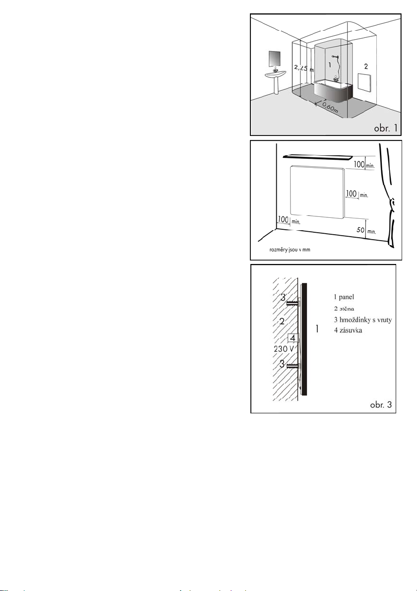
V koupelnách musí být panel instalován ve shodě s ČSN 33 2000-7-701 a smí být
umístěn v souladu s obr. 1.
Panel je zařízení třídy II , krytí IP 44. Panel nesmí být umístěn přímo pod zásuvkou
elektrického proudu.
obr.2
Elektrická instalace
Panel je vybaven dvoužilovým kabelem na 1/N 230 V / 50 Hz s vidlicí pro zapojení do zásuvky.
Ustřižení vidlice a zkrácení přívodního vodiče není důvodem ke ztrátě záruky
Barevné značení vodičů:
Fáze – hnědý,
Střední(pracovní) vodič – modrý.
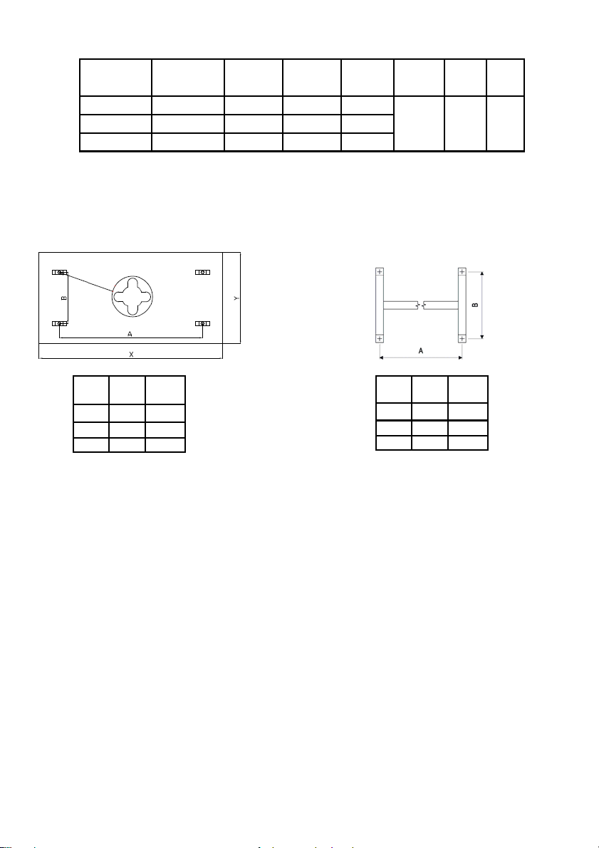
Napájecí kabel je připojený do krabice na stěně, viz. obr. 3.
Panel nesmí být umístěn těsně pod elektrickou zásuvkou.
Napájecí přívod musí být opatřen zařízením pro odpojení od sítě, u něhož se vzdálenost rozpojených kontaktů rovná nejméně 3,5 mm u všech pólů. Jestliže je
přívod tohoto spotřebiče poškozen, musí být nahrazen výrobcem nebo servisním
technikem.
.
Ovládání panelu
Doporučujeme zajistit ovládání panelu externím prostorovým termostatem s vypínačem.
Prostorový termostat udržuje nastavenou teplotu vzduchu v místnosti.
Panel je dále vybaven omezovacím termostatem, který zajišuje jeho bezpečnou funkci.
Demontáž panelu
Před demontáží odpojíme pomocí dvoupólového vypínače panel od sítě. Panel nadzvedněte svisle nahoru a do strany tak, aby se uvolnil ze
šroubů. Dále je nutné odpojit napájecí kabel z krabice na zdi.
3
Page 4
Technické údaje
Panel je možné montovat na podklady třídy hořlavosti C, D.
TYP
E 300 600x600x40 5 300 1,3
E 600 1200x600x40 10,2 600 2,6
E 850 1200x800x40 13,4 850 3,7
Rozměry (mm)
(DxŠxH)
Hmotnost
obr.4
(kg)
Výkon
(W)
Proud
(A)
Napětí
(V) AC
230 V II IP 44
Montážní rám
Třída
ochrany
Krytí
W A
(mm) B (mm)
300 335 360
600 935 360
850 935 360
W A
(mm) B (mm)
300 340 280
600 935 280
850 935 280
Záruční podmínky
Dodavatel poskytuje na výrobky záruku 24 měsíců od data prodeje. Záruka se nevztahuje na vady způsobené dopravou, nedbalou manipula-
cí a neodbornou montáží. Záruka se rovněž nevztahuje na neodborný zásah do panelu a na běžné opotřebení výrobku.
Aktuální a úplné záruční podmínky naleznete na: www.fenixgroup.eu
Potvrzení o prodeji:.......................................................................................................
Datum prodeje:....................................... Výrobní číslo:.......................................
Prodejce:.......................................................................................................
4
Page 5

Caution
• Only qualified persons may carry out work on the panel. Before launching such
work, the panel must be disconnected from the source of power. As it is made of
fragile material, great care needs to be taken during transport, manipulation and
installation.
• Do not cover the panel in any situation. The notice “NEZAKRÝVAT” (“DO NOT
COVER”) notifies that any material covering the panel may cause a fire. Furniture
must not be placed and curtains must not be hung in front of the panel (see Fig. 5)
and free circulation of air must be ensured. Dust must be removed from the panel
regularly, at least before the beginning of every heating season. Do not touch the
panel when in the bathtub or shower!
• This heater isn´t fitted with a room temperature control device. Do not use this
heater in small rooms if they are occupied by people who cannot be left in the room
by themselves unless permanent supervision is provided.
• This appliance can be used by children from the age of 8 and older, and persons
with lower physical, sensory or mental abilities or a lack of experience or knowledge providing they are under supervision or have been trained in the use of the
appliance in a safe manner and understand the possible danger. Children may not
play with the appliance. Cleaning and maintenance by the user must not be carried
out by children without supervision. Children under 3 years of age should be prevented from accessing the appliance, unless they are constantly supervised.
• Children from 3 to 8 years of age may switch the appliance on/off only if it is
placed or installed in its intended standard operating position and if they are under
supervision or have been instructed in the safe use of the appliance and if they understand the possible danger. Children from 3 to 8 years of age mustn´t insert the
plug into the socket, control or clean the appliance or carry out maintenance that is
to be done by the user.
WARNING – Some parts of this product may become very hot and cause burns.
Special attention must be paid to this fact in the presence of children and handicapped persons.
Fig.5
5
Page 6

Installation instructions
Installation, electrical connection and the first commissioning is permitted to
be performed by a worker with relevant qualifications. The panels are intended for mounting on a wall or ceiling. The producer must be consulted
before any other form of installation is attempted.
Installation on the ceiling
• Position the mounting frame in the location where the panel is to be
placed, using a pen, mark holes according to the holes on the frame.
• Drill the holes, insert the wall anchors and attach the mounting frame with
the screws.
• Always hang the panel by all four mounting slots
• Slide the panel into the mounting frame.
Installation on the wall
• Mark the holes according to the table, drill out the holes, insert the dowels
and drive the screw in to protrude approx. 5 mm. (Fig. 4)
• Always hang the panel by all four mounting slots.
• Put the panel on the screws.
Clearance distances
The distance between the bottom edge of the appliance and the floor mustn’t
be less than 50 mm; 150 mm is recommended. The clearance distance on
the side (e.g. from furniture) must be at least 100 mm, and 100 mm is the
minimum in the upward direction (see Fig. 2).
In bathrooms, the panel must be installed in accordance with the HD 60364-7
-701:2007 standard and is permitted to be located in accordance with Fig 1.
The panel is a class II appliance, with IP 44 coverage. The panel must not be
placed directly under an electric socket.
Electric installation
The panel is fitted with a two- conductor cable for 1/N 230 V / 50 Hz with a
plug for connection into a socket
Removal of the plug and shortening of the supply lead will not result in loss of
warranty
.
Colour marking of the conductors:
Phase – brown
Central (live) conductor – blue
The power supply cable is connected to a box on the wall, see Fig 3.
The panel must not be placed directly under an electric socket.
The supply cable must be fitted with a device for disconnection from the mains in which the distance between the disconnected contacts is
at least 3.5 m for all poles. If the supply cable of this appliance is damaged, it has to be replaced by the producer or a service technician.
.
Controlling the panel
We recommend controlling this panel using an external room thermostat with a switch.
The room thermostat maintains the set air temperature in the room.
Furthermore, the panel is fitted with a limit thermostat which ensures its safe operation.
Uninstalling the panel
Disconnect the panel from the mains using a two-pole switch before uninstalling it. Lift the panel upwards vertically and sideways in such a
way that it is released from the screws. Furthermore, the supply cable must be disconnected from the box on the wall.
6
Page 7

Technical specifications
Type
E 300 600x600x40 5 300 1,3
E 600 1200x600x40 10,2 600 2,6
E 850 1200x800x40 13,4 850 3,7
The panel can be installed on bases of flammability class C or D.
Fig.4
Dimensions (mm)
(LxWxH)
Weight
(kg)
Output
(W)
Current
(A)
Voltage
(V) AC
230 V II IP 44
Protection
class
Coverage
Mounting frame
W A
(mm) B (mm)
300 335 360
600 935 360
850 935 360
W A
(mm) B (mm)
300 340 280
600 935 280
850 935 280
Warranty conditions
The supplier provides a warranty of 24 months from date of sale for their product. The warranty does not cover faults caused by transportation, careless manipulation or non-professional installation. The warranty also does not apply in the case of a non-professional intervention
into the panel or to everyday wear and tear on the product.
Confirmation of sale: ………………………………………………………………………………..
Date of sale:…………………………… Serial number:……………………………………
Seller:………………………………………………………….
7
Page 8

Hinweis
• Sämtliche Eingriffe in die Platte sind nur von einer qualifizierten Person durchzufüh-
ren. Vor dem Beginn solcher Arbeit ist die Platte von der Stromquelle abzutrennen.
Weil es sich um ein zerbrechliches Material handelt, ist es nötig, bei Transport, Manipulierung und Montage höhere Acht geben.
• Keinesfalls ist die Platte abzudecken. Die Aufschrift „NICHT ABDECKEN“ macht
darauf aufmerksam, dass jedes Material, mit dem die Platte abgedeckt wird, zu
Brandentstehung führen kann. Vor die Platte ist keine Möbel zu stellen und keine
Gardine aufzuhängen (siehe Abb. 5), damit freie Luftzirkulation gesichert ist. Regelmäßig, mindestens vor jedem Heizzeitraum, den Staub aus der Platte beseitigen.
Die Platte nicht aus Wanne oder Dusche berühren!
• Dieses Heizgerät ist mit keiner Einrichtung zu Raumtemperaturüberwachung ausge-
rüstet. Deshalb darf dieses Heizgerät nicht in kleinen Räumen verwendet werden,
falls hier die Personen anwesend sind, die nicht imstande sind, diesen Raum zu
verlassen, und falls es keine ständige Aufsicht garantiert ist.
• Dieses Verbrauchsgerät kann von den Kindern ab 8 Jahren und von den Personen
mit beschränkten physischen, sinnlichen oder mentalen Fähigkeiten oder mit Mangel an Erfahrungen und Kenntnisse nur dann verwendet werden, falls sie überwacht
werden oder falls sie über sichere Verwendung des Verbrauchsgeräts informiert
wurden und eventuelle Gefahren verstehen. Die Kinder können mit dem Verbrauchsgerät nicht spielen. Die für den Benutzer vorgeschriebene Reinigung und Wartung
können von den Kindern ohne Aufsicht nicht durchgeführt werden.
• Zutritt von Kindern unter 3 Jahre zum Verbrauchsgerät sollte vermieden sein, falls
sie nicht unter ständiger Aufsicht stehen. Kinder von 3 bis 8 Jahren können dieses
Verbrauchsgerät einschalten/ausschalten, nur wenn es in seiner vorgesehenen normalen Betriebsposition installiert wurde und wenn sie unter Ausfischt stehen oder
über sichere Verwendung des Verbrauchsgeräts unterwiesen wurden und eventuelle Gefahren verstehen. Kinder von 3 bis 8 Jahren können den Stecker in Steckdose
nicht einstecken, das Verbrauchsgerät regeln, reinigen oder bei ihm die vom
Verbraucher durchgeführte Wartung durchführen.
BEMERKUNG – Einige Teile dieses Produkts können sehr heiß werden und Brandwunden verursa-
Abb.5
chen. Besondere Acht ist bei Anwesenheit von Kindern und Behinderten zu geben.
8
Page 9

Montageanleitung
Installierung, elektrischer Anschluss und die erste Inbetriebnahme sind von
einem qualifizierten Mitarbeiter durchzuführen. Die Platten sind für Wand- und
Deckenmontage bestimmt. Jede andere Montageweise ist mit dem Hersteller zu
besprechen.
Deckenmontage
• Den Montagerahmen an die zur Anbringung der Platte festgelegte Stelle
anlegen, die Öffnungen gemäß den Öffnungen auf dem Rahmen mit einem
Stift anzeichnen.
• Öffnungen bohren, Dübel einstecken und den Montagerahmen mittels Schrau-
ben befestigen.
• Die Platte immer mittels aller 4 Verankerungen aufhängen.
• Die Platte in den Montagerahmen einstecken.
Wandmontage
• Die Öffnungen gemäß der Tabelle kennzeichnen, Öffnungen ausbohren, Dübel
einstecken und Schraube einschrauben, so dass sie nicht voll eingeschraubt
ist sondern ca. 5 mm herausragt. (Abb 4)
• Die Platte immer mittels aller 4 Verankerungen aufhängen.
Abstände
Der Abstand der Unterkante des Verbrauchsgeräts vom Fußboden muss mindestens 50 mm sein, es werden 150 mm empfohlen. Der Seitenabstand, z.B.
von Möbel, muss mindestens 100 mm und der Abstand nach oben mindestens
100 mm betragen (siehe Abb. 2).
In Badezimmern ist die Platte in Übereinstimmung mit der Norm HD 60364-7701:2007 zu installieren und sie kann gemäß der Abb. 1.
Die Platte ist die Einrichtung der Klase II, Schutzart IP 44. Die Platte kann nicht
direkt unter Netzsteckdose angebracht sein.
Elektrischer Anschluss
Die Platte ist mit einem zweiadrigen Kabel für 1/N 230 V / 50 Hz mit Netzstecker ausgestattet.
Abscherung des Steckers und Verkürzung des Zuführungsdrahts stellen keinen
Grund für Garantieverfall dar
Farbige Kennzeichnung der Leiter:
Fase – braun,
Mittelleiter (Arbeitsleiter) – blau.
Das Speisekabel ist in die Dose an der Wand angeschlossen, siehe Abb. 3.
Die Platte kann nicht direkt unter Netzsteckdose angebracht sein.
Die Speiseleitung ist mit einer Einrichtung für Abtrennung vom Netz auszustatten, bei der der Abstand der geöffneten Kontakte mindestens 3,5 mm bei allen
Polen ist. Falls die Speiseleitung dieses Verbrauchsgeräts beschädigt ist, ist sie
vom Hersteller oder seinem Servicetechniker zu ersetzen.
.
Bedienung der Platte
Es wird empfohlen, die Bedienung der Platte durch einen externen Raumthermostat mit Schalter zu sichern.
Der Raumthermostat erhält die im Raum eingestellte Lufttemperatur.
Darüber hinaus ist die Platte mit einem Begrenzungsthermostat ausgestattet, der seine sichere Funktionsfähigkeit sichert.
Demontage der Platte
Vor der Demontage ist die Platte mittels des zweipoligen Schalters vom Netz abzutrennen. Die Platte in vertikaler Richtung nach oben und
seitlings anheben, damit sie sich aus den Schrauben löst. Darüber hinaus ist es nötig, das Speisekabel aus der Dose an der Wand abzutrennen.
9
Page 10

Technische Angaben
TYP
E 300 600x600x40 5 300 1,3
E 600 1200x600x40 10,2 600 2,6
E 850 1200x800x40 13,4 850 3,7
Die Platte kann auf die Untergründe mit der Brennbarkeitsklasse C, D montiert sein.
Abb.4
Garantiebedingungen
Der Lieferant gewährt für die Produkte die Garantie von 24 Monaten ab dem Verkaufsdatum. Die Garantie bezieht sich nicht auf die durch
Transport, nachlässige Manipulation oder unsachgemäße Montage verursachten Mängel. Die Garantie ist nicht einmal für unsachgemäßen
Eingriff in die Platte und für gewöhnliche Abnutzung des Produkts gültig.
Abmessungen
(mm)
(LxBxT)
W A
(mm) B (mm)
300 335 360
600 935 360
850 935 360
Gewicht
(kg)
Leistung
(W)
Strom
(A)
Spannung
(V) AC
230 V II IP 44
Schutzklasse Schutzgrad
Montagerahmen
W A
(mm) B (mm)
300 340 280
600 935 280
850 935 280
Verkaufsbestätigung:…………………………………………………………………………………………
Verkaufsdatum:……………………………………… Produktionsnummer:………………………………
Verkäufer:.……………………………………………………………………
10
Page 11

11 12
Page 12

Fenix s.r.o.
Jaroslava Ježka 1338/18a, 790 01 Jeseník
tel.: +420 584 495 442, fax: +420 584 495 431
e-mail: fenix@fenixgroup.cz , http://www.fenixgroup.cz
Fenix Trading s.r.o.
Slezská 2, 790 01 Jeseník
tel.: +420 584 495 304, fax: +420 584 495 303
e-mail: fenix@fenixgroup.cz , http://www.fenixgroup.cz
 Loading...