

Page 1

REFLECTING POOL
Page 2
2
1
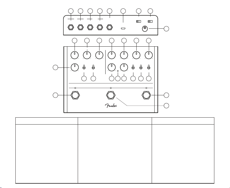
1. Reverb Footswitch & LED
2. Extra
3. Decay
4. Damp
5. Level (Reverb)
6. Reverb Type Switch
7. Variation Switch
2523222120 24
IN OUT
L/MONO
R L/MONO R
TAP
FS
USB
3 4 5 8 9 10 11
REVERB DELAY
TYPE
EXTRA RATE DEPTH
6 7
12 13 14 15 16 17
REFLECTING POOL
Delay Controls Rear Panel ControlsReverb Controls
8. Time
9. Feedback
10. Mix
11. Level (Delay)
12. Rate
13. Rate LED Indicator
14. Depth
15. Delay Type Switch
16. Subdivision Switch
17. Quality Switch
18. Delay Footswitch & LED
19. Delay Tap Tempo Footswitch & LED
BYPASS
9V DC
INPUT
MIXLEVELDAMP TIME FEEDBACK LEVELDECAY
TYPE SUBD QUALIT YVARIATION
26 27
DELAYTAPREVERB
LEDs
28
18
19
20. L/Mono Input Jack
21. Right Input Jack
22. L/Mono Output Jack
23. Right Output Jack
24. Tap Footswitch Jack
25. USB Jack
26. Bypass Mode Switch
27. LED Kill Switch
28. DC Power Connector
Page 3
REFLECTING POOL
Thanks for purchasing the Reflecting Pool delay-reverb pedal. This highly
sophisticated digital effect uses advanced DSP technology to create lush
and complex time-based effects. Featuring independently switchable
delay and reverb, dedicated tap tempo footswitch, stereo I/O and a wide
selection of different algorithms and variations — including modulation,
shimmer, gated, and reverse sounds.
DESIGNED IN CALIFORNIA, U.S.A.
Page 4

REVERB CONTROLS
Reverb Bypass Footswitch & LED
Footswitch bypasses reverb effect. LED Illuminates when reverb is active.
Decay
This control adjusts the reverb decay time, or length of the reverb signal.
Counterclockwise settings produce smaller room and ambient sounds, while
settings closer to fully clockwise can produce the sound of huge spaces.
Damp
Attenuates high frequencies and “darkens” reverb tail.
Level (Reverb)
Controls “wet/dry” reverb signal mix.
Extra
Modifies an “extra” algorithm-specific parameter. On “Hall” and
“Room”reverb settings it controls “tilt” between high and low
frequency decay times. On Special “Shimmer” setting (see
“Variation Switch” below) it controls regeneration of cascading octaves.
On Special “Gated/Reverse” setting (see “Variation Switch” below) it
controls reverb tail shape, and on Special “Modulated” setting it controls
modulation depth.
Type Switch
Toggle among Hall, Room and Special reverb types
Variation Switch
Toggles among three different variations for each reverb type:
Reverb
Type Switch
HALL
ROOM
SPECIAL
Description
Classic diffuse space with a
sense that walls are far apart.
Smaller, more lively feel
than HALL.
Classic modern reverb effect with
octave-up pitch shift in loop between
reverb input and output. Successive
octaves are added as reverb decays,
imparting a blooming, atmospheric effect.
Small-space reverb, plus gated and
reverse reverb. Set EXTRA and LEVEL
control knobs at full clockwise position
for “full-wet” reverse effect.
Very large space with some pitch
modulation. Ideal for ambient pads and
swells.
Variation
Switch
1: small hall
2: medium hall
3: large hall
1: small room
2: medium room
3: large room
1: Shimmer
2: Gated/
Reverse
3: Modulated
“Extra” Knob Function
Controls amount of low-frequency rolloff in reverb decay. Turn
EXTRA knob counter-clockwise for more bass in reverb tail;
clockwise for less (similar to a bass cut).
Controls amount of regeneration into octave-up reverb effect,
which determines how much of the octave is heard and how
Controls reverb tail shape. At full counterclockwise, shape is a
typicaldecaying taper. At noon produces a gated shape; at full
much octaves will “stack.”
clockwise produces reverse reverb.
Controls reverb modulation depth
(modulation rate fixed at 0.1 Hz).
Page 5

DELAY CONTROLS
Delay Bypass Footswitch & LED
Footswitch bypasses delay effect. LED Illuminates when delay is active.
Delay Tap Tempo Footswitch & LED
Set delay time by tapping two or more times at desired rate. LED flashes in
sync with delay time.
Time
Turn Time control knob to set delay time from 10ms to 1 second. To select
various rhythmic subdivisions, press and hold Tap footswitch while turning
Time control knob. Select rhythmic subdivisions including (clockwise): 16th
note, dotted 16th note, 8th note, 8th note (triplet), dotted 8th note, quarter
note, half note. After selection, release Tap footswitch.
Feedback
Controls number of delay repeats.
Mix
Controls blend between main delay and secondary delay tap defined by
SUBD toggle switch (see “SUBD Switch” below). At minimum setting, main
delay only is heard. Secondary delay tap becomes increasingly audible as
knob is turned. At maximum setting, secondary delay tap only is heard.
Delay Type Switch
DIGITAL
ANALOG
TAPE
ECHO
Authentic digital delay emulation with three
modes available via the Quality switch.
Analog (bucket brigade) delay emulation with
three modes available via the Quality switch.
Authentic tape-echo emulation with three
modes available via the Quality switch:
Level (Delay)
Controls “wet/dry” delay signal mix.
Rate
Controls modulation speed.
Rate LED
Flashes in time with modulation speed.
Depth
Controls modulation depth.
Type Switch
Toggle among Digital, Analog or Tape delay types.
Subdivision Switch
Enables selection of rhythmic subdivision for second delay tap (secondary
delay time is a subdivision of main delay time). Rhythmic subdivision values
are: 50% (8th note relative to quarter note), 66% (quarter note triplet
relative to quarter note) and 75% (dotted 8th note relative to quarter note).
Quality Switch
Enables selection of 3 distinct delay repeat types (useful as progressive
reduction in delay repeat quality).
Variation SwitchDescription
1: Crystal-clean delay.
2: Some audible signal degradation similar to lo-fi digital hardware.
3: Grunge with less high end and the sound of old-school signal processors.
1: Softer repeats and less highs and lows than digital.
2: Less fidelity and slightly more distortion than NOS mode.
3: The highest amount of bass and treble cut, the most distortion, and
even some artifacts from the bucket-brigade sampling process.
1: The sound of a 15 ips studio tape echo unit.
2: Lower degree of fidelity and higher degree of tape saturation
than NOS mode.
3: Even lower degree of fidelity and higher degree of tape saturation than NOS
and classic modes. Use DEPTH and RATE control knobs (especially with RATE
at full clockwise) for realistic wow and flutter of old tape.
Page 6

REAR PANEL CONTROLS
Left Input Jack
High-impedance input suitable for electric guitar, bass, acoustic guitars with pickup systems, keyboards and other instruments.
Right Input Jack
High-impedance input suitable for electric guitar, bass, acoustic guitars with pickup systems, keyboards and other instruments.
Left Output Jack
Low-impedance output jack connects to amp or to next effect pedal in signal chain.
Right Output Jack
Low-impedance output jack connects to amp or to next effect pedal in signal chain.
Tap Footswitch Jack
For connecting a momentary footswitch to set tap tempo remotely.
DC Power Connector
Standard center-negative 9VDC jack for use with appropriate power supplies.
Bypass Type Switch
Enables selection of “Trails” (DSP bypass) or relay-based “True” bypass.
LEDs Switch
Turns control-knob illumination on and off.
USB Port
Connection point for firmware updates (when available).
Page 7

NOTES:
FENDER MUSICAL INSTRUMENTS CORPORATION
A PRODUCT OF:
CORONA, CALIFORNIA, USA
Fender® is a registered trademark of FMIC.
Copyright © 2019 FMIC. All rights reserved.
P/N 7717100000 - REV 2
Important Safety Instructions
•WARNING: To prevent damage, fire or shock hazard, do not expose the unit or its AC
power to rain or moisture.
•Do not alter the AC plug of the connected power adapter
•Do not drip or splash liquids on the unit.
•No user serviceable parts inside, refer servicing to qualified personnel only.
• WARNING: The unit must only be connected to a safety agency certified, regulated,
power source (adapter), approved for use and compliant with applicable local and
national regulatory safety requirements.
• Unplug the AC power adapter before cleaning the unit exterior. Use only a damp cloth
for cleaning and then wait until the unit is completely dry before reconnecting it to power.
• Amplifiers and loudspeaker systems, and ear/headphones (if equipped) are capable
of producing very high sound pressure levels which may cause temporary or permanent
hearing damage. Use care when setting and adjusting volume levels during use.
THIS DEVICE COMPLIES WITH PART 15 OF FCC RULES. OPERATION IS SUBJECT TO
THE FOLLOWING TWO CONDITIONS: (1) THIS DEVICE MAY NOT CAUSE HARMFUL
INTERFERENCE, AND (2) THIS DEVICE MUST ACCEPT ANY INTERFERENCE RECEIVED,
INCLUDING INTERFERENCE THAT MAY CAUSE UNDESIRED OPERATION.
Additional Languages
Manual available in additional languages at:
www.fender.com/support
IMPEDANCES:
POWER SUPPLY:
POWER REQUIREMENTS:
DIMENSIONS:
WEIGHT:
Product specifications subject to change without notice
Specifications
INPUT: 1MΩ OUTPUT: 600Ω
9VDC regulated adapter,
5.5 x 2.1 mm barrel connector, center negative
250mA @ 9VDC
6.7” x 4.9” x 2.5” (170mm x 124.5mm x 63.5mm)
1.5lbs (.68kg)
Page 8

© FENDER MUSICAL INSTRUMENTS 2019
 Loading...