

Fender FWG 2020 Owner's Manual
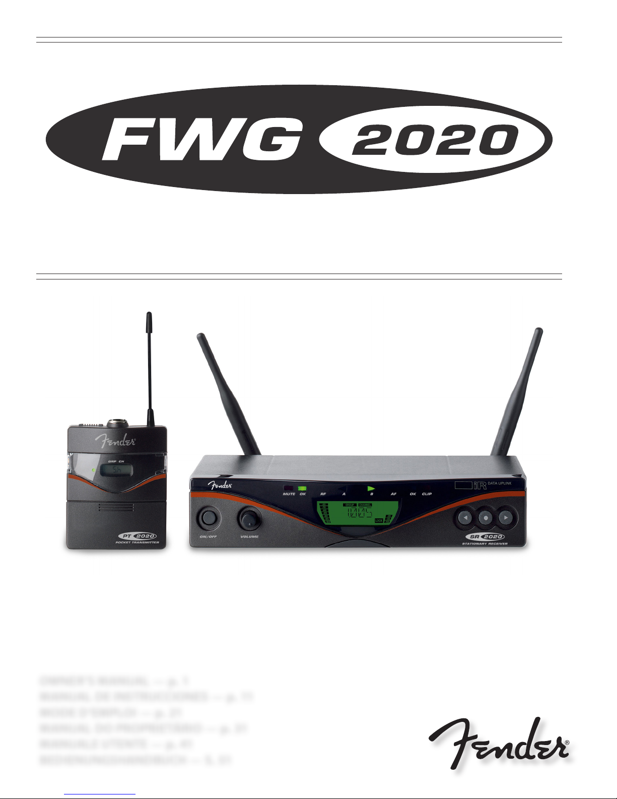
UHF Wireless System™
ENGLISH ESPAÑOL FRANÇAIS ITALIANO DEUTSCHPORTUGUÊS
OWNER’S MANUAL — p. 1
MANUAL DE INSTRUCCIONES — p. 11
MODE D’EMPLOI — p. 21
MANUAL DO PROPRIETÁRIO — p. 31
MANUALE UTENTE — p. 41
BEDIENUNGSHANDBUCH — S. 51
NOT USED
NO USADO
NON UTILISÉ
NÃO USADO
NON USATO
NICHT VERWENDET
ii
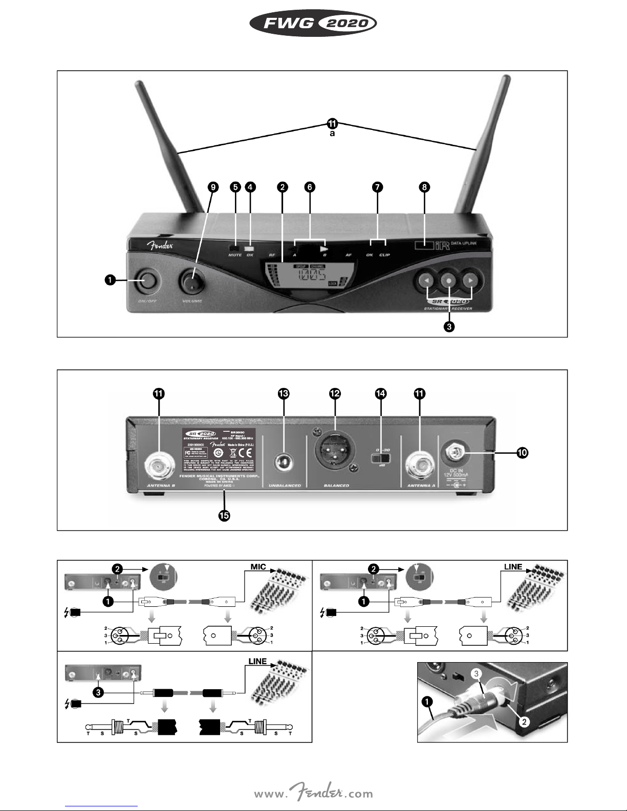
Fig. 1
Fig. 2
Fig. 8
Fig. 9
iii
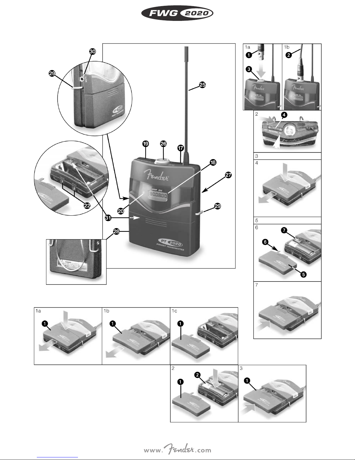
Fig. 4 Fig. 12
Fig. 5
iv
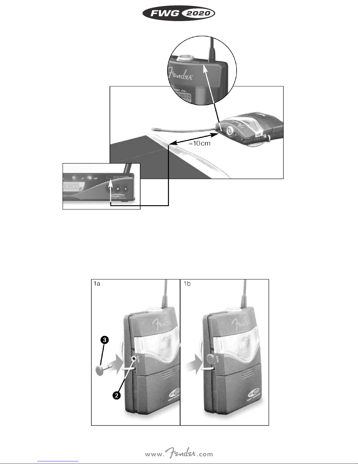
Fig. 11
Fig. 17
v
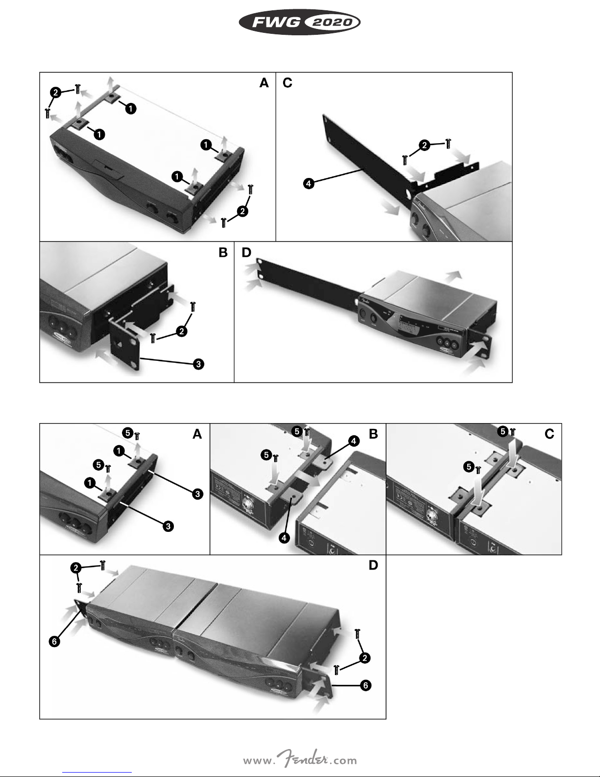
Fig. 6
Fig. 7
vi
Thank you . . .
. . . for purchasing a Fender product. This manual contains important
instructions for setting up and operating your equipment. Please take
a few minutes to read the instructions below carefully before operating the equipment. Please keep the manual for future reference. We
hope you enjoy using your system!
Symbols Used
The lightning ash with arrow point in an equilateral trian-
gle means that there are dangerous voltages present
within the unit.
The exclamation point in an equilateral triangle on the
equipment indicates that it is necessary for the user to
refer to the User Manual. In the User Manual, this symbol
marks instructions that the user must follow to ensure
safe operation of the equipment.
Important Note
i
• The display on your bodypack transmitter indicates the mini-
• To ensure an accurate readout, do not use any batteries other
- AA size (FR6) lithium batteries,
or
- High quality AA size NiMH rechargeable batteries with a capacity
- In the “BAT.TYP” menu, select the battery type you inserted
- In “AUTO” mode, using weak or very old batteries may cause
• Since the chemical parameters of batteries take some time to
• Lithium batteries have a life of up to 14 hours. The display, how-
Transmitter Battery
mum remaining battery capacity in transmitter operating hours.
than new, high quality AA size (LR6) alkaline dry batteries from
Duracell or Energizer,
of 2100 mAh or higher.
(“LR6”, “FR6”, “HR6 (NiMH)) or automatic battery detection mode
(“AUTO”).
incorrect capacity indications. In this case, select the battery type
manually.
stabilize, the system may correct the battery indication (type
and remaining capacity) about 10 to 30 minutes after switching
power to the transmitter on.
ever, will only indicate a maximum of 10 hours. With new lithium
batteries, the display will constantly indicate “10h” during the
rst four operating hours.
Safety and Environment
Safety
• Do not expose it to direct sunlight, excessive dust, moisture,
rain, mechanical vibrations, or shock.
• Do not spill any liquids on the equipment and do not drop any
objects through the ventilation slots in the equipment.
Safety
• The equipment may be used in dry rooms only.
• Before connecting the equipment to power, check that the AC
mains voltage stated on the included power supply is identical
to the AC mains voltage available where you will use the equipment.
• Operate the equipment with the included power supply with an
output voltage of 12 VDC only. Using adapters with an AC output
and/or a dierent output voltage may cause serious damage to
the equipment.
• The equipment should be opened, serviced, and repaired by
authorized personnel only. The equipment contains no user-serviceable parts.
• Operate the equipment o voltages between 90 VAC and 240
VAC only. Using a dierent power voltage may cause serious
damage to the unit!
• If any solid object or liquid penetrates into the equipment, shut
down the sound system immediately. Disconnect the power cable from the power outlet immediately and have the equipment
checked by Fender service personnel.
• Do not place the equipment near heat sources such as radiators,
heating ducts, or ampliers, etc. and do not expose it to direct
sunlight, excessive dust, moisture, rain, mechanical vibrations, or
shock.
• To avoid hum or interference, route all audio lines, particularly
those connected to the inputs, away from power lines of any
type. If you use cable ducts or conduits, be sure to use separate
ones for the audio lines.
• Clean the equipment with a moistened (not wet) cloth only. Be
sure to disconnect the equipment from the power outlet before
cleaning the equipment! Never use acidic or scouring cleaners or
cleaning agents containing alcohol or solvents since these may
damage the enamel and plastic parts.
• Use the equipment for the applications described in this manual only. Fender cannot accept any liability for damages resulting
from improper handling or misuse.
Environment
• Be sure to dispose of dead batteries as required by local waste
disposal rules. Never throw batteries into a re (risk of explosion)
or garbage bin.
• The packaging of the equipment is recyclable. Dispose of the
packaging in an appropriate container provided by the local
waste collection/recycling entity and observe all local legislation
relating to waste disposal and recycling.
• When scrapping the equipment, remove the batteries, separate
the case, circuit boards, and cables, and dispose of all components in accordance with local waste disposal rules.
ENGLISH
1
FCC STATEMENT
The transmitter has been tested and found to comply with the
limits for a low-power auxiliary station pursuant to Part 74 of the
FCC Rules. The receiver has been tested and found to comply with
the limits for a Class B digital device, pursuant to Part 15 of the FCC
Rules. These limits are designed to provide reasonable protection
against harmful interference in a residential installation. This equip-
ENGLISH
ment generates, uses, and can radiate radio frequency energy and,
if not installed and used in accordance with the instructions, may
cause harmful interference to radio communications. However,
there is no guarantee that interference will not occur in a particular
installation. If this equipment does cause harmful interference to
radio or television reception, which can be determined by turning
the equipment o and on, the user is encouraged to try to correct
the interference by one or more of the following measures:
• Reorient or relocate the receiving antenna.
• Increase the separation between the equipment and the receiver.
• Connect the equipment into an outlet on a circuit dierent from
that to which the receiver is connected.
• Consult the dealer or an experienced radio/TV technician for
help.
Shielded cables and I/O cords must be used for this equipment to
comply with the relevant FCC regulations. Changes or modications not expressly approved in writing by FMIC may void the user’s
authority to operate this equipment.
The receiver complies with Part 15 of the FCC Rules. Operation is
subject to the following two conditions: (1) this device may not
cause harmful interference, and (2) this device must accept any
interference received, including interference that may cause undesired operation.
USA only: FCC CONSUMER ALERT
Most users do not need a license to operate this wireless system.
Nevertheless, operating this system without a license is subject to
certain restrictions: the system may not cause harmful interference;
it must operate at a low power level (not in excess of 50 milliwatts);
and it has no protection from interference received from any other
device.
Purchasers should also be aware that the FCC is currently evaluating
use of wireless systems, and these rules are subject to change. For
more information, call the FCC at 1-888- CALL-FCC (TTY: 1-888-TELLFCC) or visit the FCC’s website at www.fcc.gov/cgb/wirelessmicrophones.
1. GENERAL
Introduction
The FWG 2020 wireless system comprises a stationary diversity receiver and the bodypack transmitter. The receiver and transmitter operates in a 30 MHz sub-band of each frequency set within the 500 MHz
to 865 MHz UHF band. You can select the receiving frequency from the
preprogrammed frequency groups and sub-channels of your receiver
or set it directly in 25 kHz-increments. The bodypack transmitter is set
to the parameters selected on the receiver via infrared transmission.
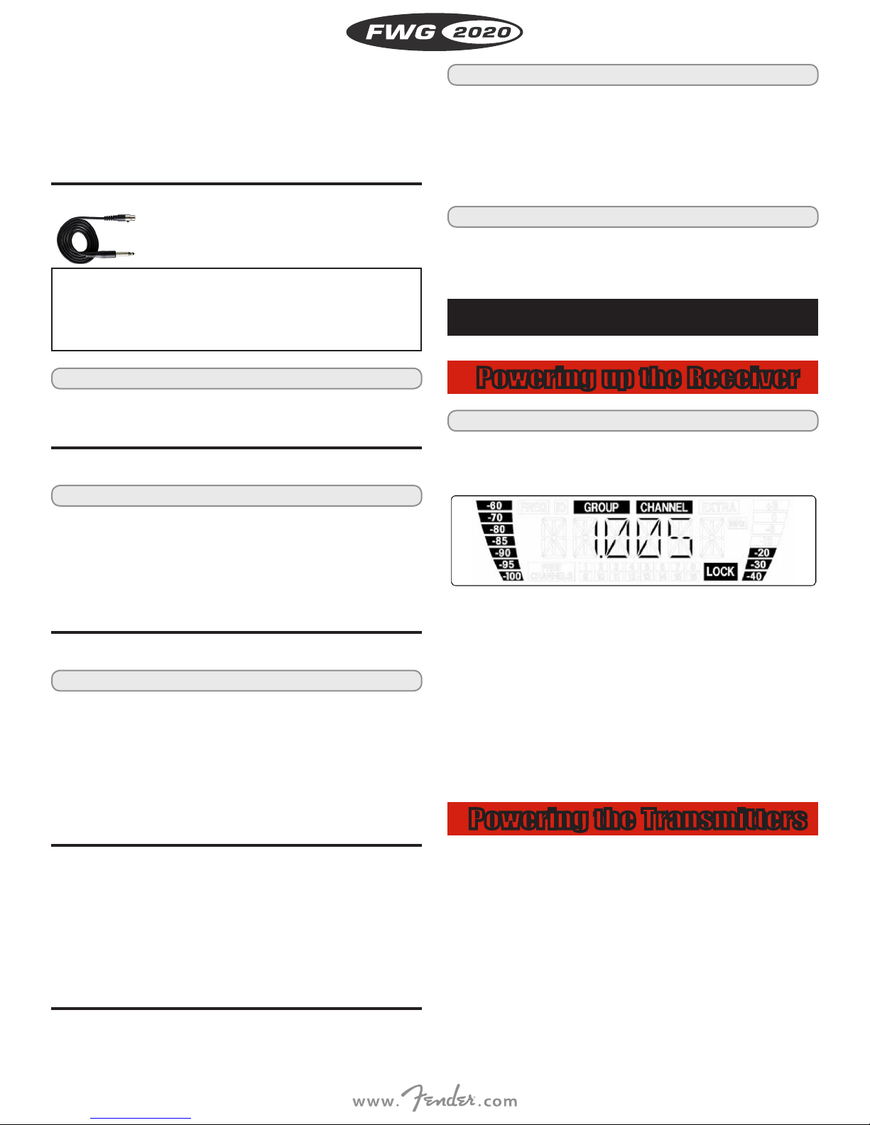
Accessories/Parts
Part Number Item
7704710000 PASSIVE DIRECTIONAL ANTENNA
7744711000 ACTIVE DIRECTIONAL ANTENNA
7704712000 PASSIVE WD-BND OMNIDIRECTIONAL ANTENNA
7704713000 ACTIVE WD-BND OMNIDIRECTIONAL ANTENNA
7704714000 POWER SW SUPPLY 12V 500 MA MULTIPLUG
7704715000 BODY PACK TRANSMITTER CHARGING STATION
7704716000 PT 2020 WIRELESS BODY PACK TRANSMITTER
7704717000 FMKPS ANTENNA CABLE 2 FT 65 CM
7704718000 FMKA5 ANTENNA CABLE 16 FT 5 M
7704719000 FMKA20 ANTENNA CABLE 66 FT 20 M
7704720000 FRONT MOUNT ANTENNA RACKMOUNT KIT
7704722000 ITC3 INSTRUMENT TRANSMITTER CABLE 3 FT
Receiver
Front Panel
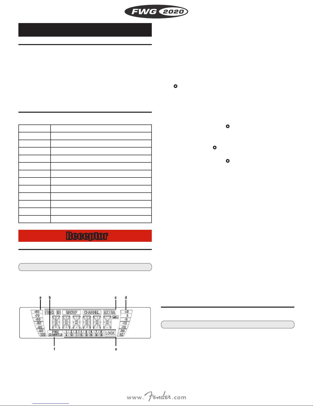
i Refer to g. 1 on page iii.
1 POWER: Switches power to the unit on or o.
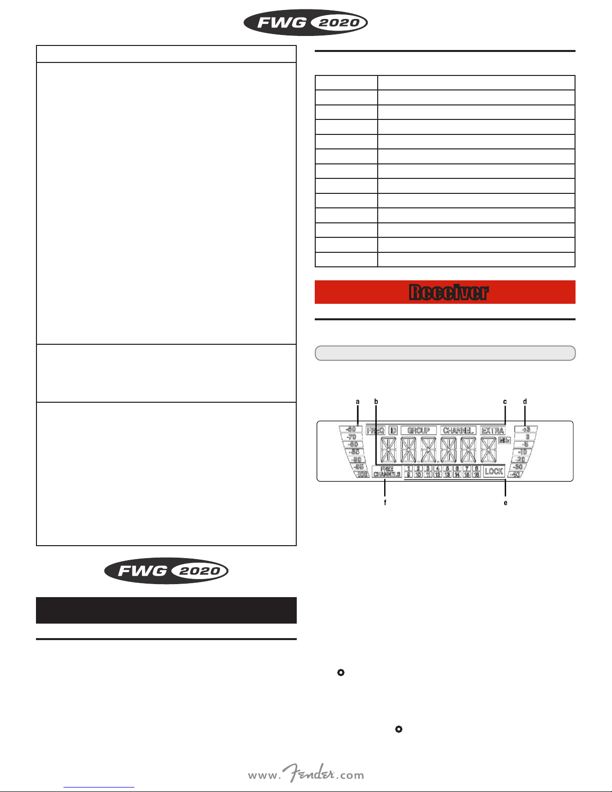
2 LCD display: The receiver provides a back-lit LCD display.
The display indicates all receiver parameters:
a RF bar-graph indicating the eld strength of the received
signal
b Alphanumeric display of the current setting
c Parameter to be adjusted, mode
d Audio bar-graph indicating the received audio level
e LOCK symbol
f Available channels (for automatic frequency setup)
• If one or more warning functions are activated, the display will be
back-lit in red when a critical condition occurs. As long as all parameters are within their normal ranges, the display is back-lit in green.
3 t l u : These three keys set the various parameters of the receiver.
• In LOCK mode:
Short push on t or u : scrolls through the Frequency, Preset,
and receiver Name screens.
Long push on l : selects SETUP mode.
• In SETUP mode only:
2

Short push on l : Calls up a parameter for adjustment or con-
rms a selected value.
Long push on l : selects LOCK mode.
Short push on t : selects a menu item or decreases a parame-
ter value.
Shor t push on u : selects a menu item or increases a parameter
value.
4,5 RF LEDs: The green OK LED (4) is lit to indicate the receiver is
receiving RF signal, the red MUTE LED (5) indicates that no signal is
being received.
6 A and B diversity LEDs: These two LEDs are lit to indicate which
of the two antennas is currently active.
7 AF LEDs: Indicate the received audio level:
OK (green): -40 dB to +3 dB
CLIP (red): >3 dB (overload)
8 Infrared emitter: Transmits frequency data from the receiver to
the bodypack transmitter. The infrared emitter has a very narrow
radiation angle (approx. 10°) and a maximum range of 8 inches (20
cm) to make sure only one transmitter will be tuned to the same
frequency.
9 Output level control: This retractable rotary control attenuates
the level of the balanced audio output continuously by 0 to 30 dB.
Rear Panel
i Refer to g. 2 on page iii.
10 DC IN: Locking DC input for connecting the included power
supply.
11 ANTENNA A/B: BNC sockets for connecting the two supplied UHF
antennas or optional remote antennas.
12 BALANCED: Balanced 3-pin XLR audio output for connecting to a
balanced input on a mixing console or amplier.
13 UNBALANCED: Unbalanced 1/4” TS audio output jack for con-
necting to an instrument amplier.
14 Output level switch: Slide switch for matching the BALANCED
output level to the input gain of the equipment connected
to the receiver. The switch has two positions, 0 and -30 dB. The
UNBALANCED output level is not adjustable.
15 Type plate indicating available carrier frequency ranges and
approval information.
MUTE/PRG: The audio signal is muted. Sliding the switch to
“MUTE/PRG” places the transmitter in programming mode. To
switch the audio signal back on, slide the switch to “ON”.
OFF: Power to the transmitter is o. The status LED (20) is dark.
20 Status LED: This bi-color LED indicates the following conditions:
Green: The battery will last for more than one hour, the transmit-
ter is in normal mode.
Red: The battery will be dead in less than one hour and/or the
audio signal is muted. Flashing red: Error message in the display.
Flashing red: Error message in the display.
O: Power to the transmitter is o or the transmitter is in program-
ming mode.
22 Charging contacts: The recessed charging contacts allow you to
charge a rechargeable battery on the optional charger without
having to remove the battery from the transmitter.
25 Antenna: Permanently connected, exible antenna.
26 Audio input: 3-pin mini XLR connector with line level pins that
automatically match the connector pin-out of the supplied ITC3
instrument cable. The ITC3 instrument cable lets you connect an
electric guitar, electric bass, or remote keyboard to the bodypack
transmitter.
27 Frequency sticker: Sticker attached to the transmitter, indicating
the available carrier frequency range and approval data.
28 Battery compartment for the supplied AA size 1.5 V dry battery
or a commercial 1.2 V, ≥2100 mAh NiMH AA size rechargeable
battery. The viewing window lets you check if there is a dry or
rechargeable battery inside the battery compartment. You can
also insert a white lettering strip (supplied) or a color code strip
(optional) into the viewing window.
29 Belt clip for xing the transmitter to your belt.
30 MUTE jack: This jack allows you to connect the supplied terminal
connector for locking the ON-MUTE/PRG-OFF switch to prevent
operating errors.
31 Gain control: This rotary control inside the battery compartment
allows you to match the bodypack transmitter input gain to the
instrument you connected to the transmitter.
2. SETTING UP
Rack Mounting Receiver
ENGLISH
Bodypack Transmitter
i Refer to g. 4 on page iv.
17 Infrared sensor: Receives the infrared signal emitted by
the receiver for automatically setting the transmitter’s carrier
frequency.
18 LCD display: Indicates the selected frequency in MHz or as a Preset
sub-channel, current mode, error messages, as well as the available
battery capacity in 1-hour increments for dry and 2-hour increments for rechargeable batteries.
19 ON-MUTE/PRG-OFF: This slide switch provides three positions:
ON: The output signal is fed to the transmitter for transmission to
the receiver (normal mode). The status LED (20) is lit green.
• If you install one or more receivers into a 19” rack, either mount
the supplied antennas on the receiver front panel(s) or use remote
antennas. This is the only way to ensure optimum reception quality.
Single Receiver
i Refer to g. 6 on page vi.
1. Unscrew the four rubber feet (1) from the receiver bottom panel.
2. Unscrew the two xing screws (2) from each side panel.
3. Use the xing screws (2) to screw the short bracket 3 to one side
panel and the long bracket (4) to the other side panel. The brackets
are contained in the supplied rack mounting kit.
4. Install the receiver in your rack.
3

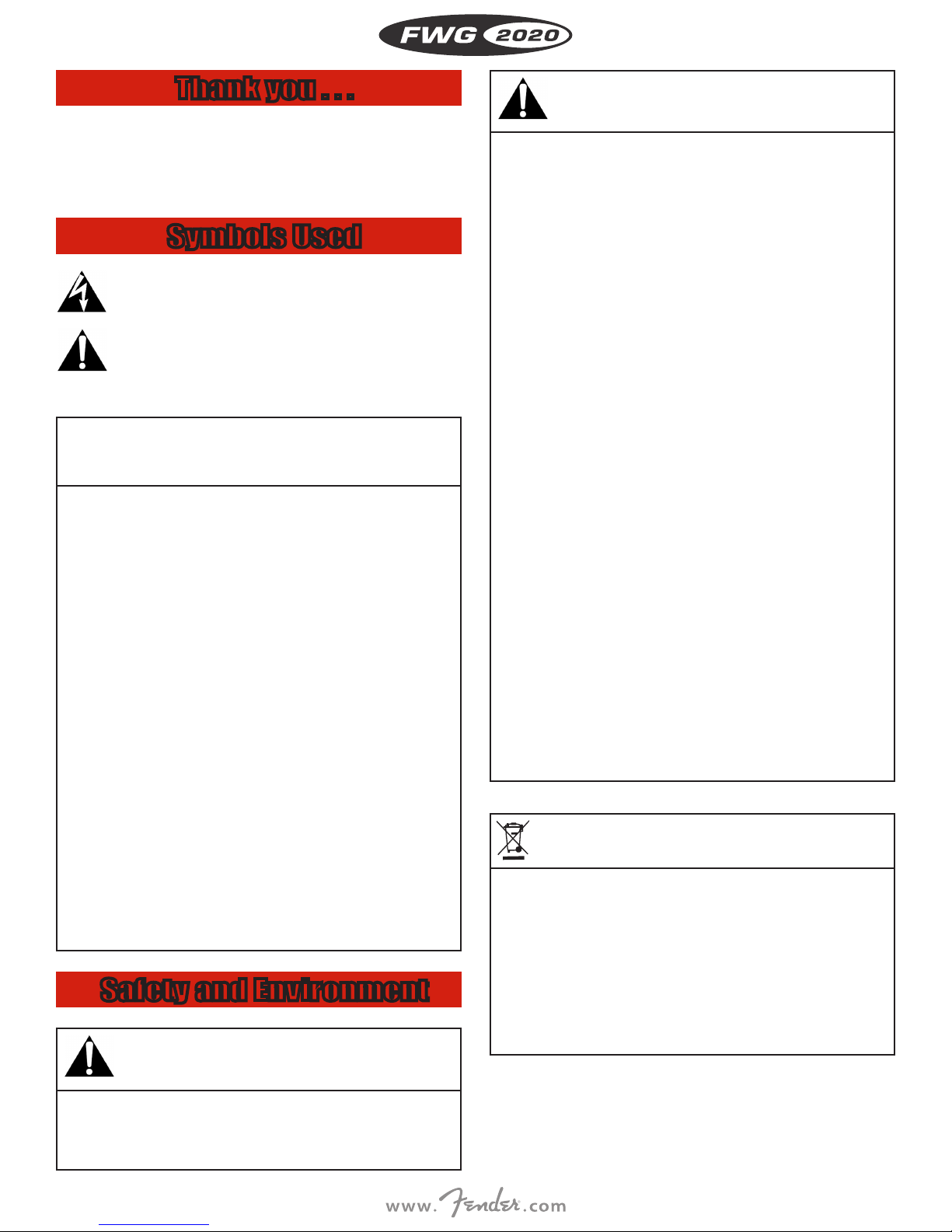
Two Receivers Side by Side
i Refer to g. 7 on page vi.
1. Unscrew the four rubber feet (1) from each receiver’s bottom panel
and remove the screws (5) from the rubber feet (1).
2. Unscrew the two xing screws (2) from the right-hand side panel
ENGLISH
of one receiver and from the left-hand side panel of the other
receiver.
3. Fix the connecting strips (4) on the rst receiver using the screws
(5) you removed from the rubber feet.
4. To join the two receivers, slide the connecting strips (4) on the
rst receiver through the free slots in the side panel of the second
receiver. Make sure to align the hole in each connecting strip (4)
with the appropriate threaded hole in the bottom panel of the second receiver.
5. Fix the connecting strips (4) on the second receiver using the
screws (5) you removed from the rubber feet (1).
6. Screw a short bracket (6) to the outer side panel of each receiver
using for each bracket two of the screws (2) you removed from the
receiver side panels.
7. Install the receivers in your rack.
Connecting Antennas
The supplied ¼-wave antennas can be mounted quickly and easily
and are suitable for applications where a direct line of sight between
the transmitter and the receiver antenna is available and a wireless
system has to be set up within a very short time.
rack using the supplied Rack Mount Kit.
• If you install one or ore receivers into a 19” rack, either mount the
supplied antennas on the receiver front panel(s) or use remote
antennas. This is the only way to ensure optimum reception
quality.
Connecting the Receiver to
a Mixer/Amplifier
You can use both the XLR and ¼” jack outputs to connect the receiver
to your mixer or amp. Use the receiver’s AUDIO Menu to adjust the
output level as required.
• Connect the audio output to the desired input:
- XLR output -> XLR Cable -> XLR input
- 1/4” output -> unbalanced cable -> 1/4” input
Attenuation Switch
• The attenuation switch lets you match the receiver’s BALANCED
output level to the input gain of the connected equipment.
• If you use a MIC input on your mixer, set the attenuation switch
to -30 dB. This reduces the output level by 30 dB and prevents the
input from being overloaded.
• The UNBALANCED line output level is not adjustable.
Connecting the Receiver to
Power
Remote Antennas
• If reception is less than ideal at the receiver’s position, use remote
antennas:
- Connect the remote antennas to the antenna sockets on the
receiver rear panel.
- Use RG58 or RG213 cable to connect the antennas.
Antenna Front-mount Cable
• Use the Front Mount Antenna Rack Mount Kit (P/N 7704720000) to
mount the ¼-wave antennas on the front panel.
Positioning the Receiver
Reections o metal parts, walls, ceilings, etc. or the shadow eects
of musicians and other people may weaken or cancel the direct transmitter signal.
For best results, place the receiver or remote antennas as follows:
• Place the receiver/antennas near the performance area (stage).
Make sure, though, that the transmitter will never get any closer to
the receiver than 10 ft (3 m).
• Check that you can see the receiver from where you will be using
the transmitter.
• Place the receiver at least 5 ft. (1.5 m) away from any big metal
objects, walls, scaolding, ceilings, etc.
• You can either use the receiver freestanding or mount it in a 19”
i Refer to g. 9 on page iii.
1. CAUTION: Check that the AC mains voltage stated on the
included power supply is identical to the AC mains voltage
available where you will use your system. Using the power
supply with a dierent AC voltage may cause damage to the
unit.
2. Plug the cable (1) on the included power supply into the DC IN
socket (2) on the receiver rear panel and screw down the DC connector (3).
3. Plug the power supply into a convenient power outlet.
LOCK Mode
The receiver is electronically locked so that you cannot make any unintended adjustments. The “LOCK” label is shown on the display.
• To enter SETUP mode, press and hold the l key until the “LOCK”
label disappears.
Bodypack Transmitter
Inserting the Battery
i Refer to g. 5 on page iv.
1. Open the battery compartment cover (1).
2. Insert the supplied battery (2) into the battery compartment,
4
aligning the battery with the polarity symbols. If you insert the
battery the wrong way, the transmitter will not be powered.
3. Close the battery compartment cover (1).
• Alternatively to the supplied LR6 alkaline dry battery, you may use
an FR6 lithium battery or a commercial 1.2 V AA size (HR6), ≥2100
mAh rechargeable battery.
Connecting an instrument
Only use the supplied ITC3 instrument cable with the
Bodypack Transmitter.
Please note that Fender cannot guarantee that the
bodypack transmitter will work perfectly with products
i
from other manufacturers and any damage that may
result from such use is not covered by the Fender warranty scheme.
i Refer to g. 4 on page iv.
2. Set the ON-MUTE/PRG-OFF switch (19) to “MUTE/PRG”. The display
will alternately indicate the currently selected frequency and “PRG
IR ”.
3. In the “BAT.TYP” menu, select the battery type you inserted: “LR6”,
“FR6”, “HR6 (for NiMH rechargeable batteries) or “AUTO”. In “AUTO”
mode, the transmitter automatically identies the battery type.
i Refer to g. 11 on page v.
4. Point the infrared sensor (1) on the transmitter at the infrared emitter (2) on the receiver from a distance of 4 inches (10 cm) max. to
activate the selected mode.
3. OPERATING NOTES
ENGLISH
i Refer to g. 12 on page iv.
• Plug the mini XLR connector (1) on the ITC3 instrument cable (2)
into the audio input connector (3) on the bodypack transmitter.
Locking the ON-MUTE/PRG-OFF Switch
i Refer to g. 17 on page v.
1. Plug the supplied terminal connector (3) into the REMOTE MUTE
jack (2) on the bodypack transmitter. The ON-MUTE/PRG-OFF
switch on the bodypack transmitter is electronically locked. You
can not mute the transmitter unintentionally.
2. To unlock the ON-MUTE/PRG-OFF switch, disconnect the terminal
connector (3) from the REMOTE MUTE jack (2).
Setting Input Gain
i Refer to g. 12 on page iv.
1. (4) Open the battery compartment on the bodypack transmitter.
2. Play a few bars on your instrument (the louder the better).
3. (6) Use the integrated screwdriver (6) on the battery compartment
cover (5) to set the gain control (7) to the point where the signal
will optimally drive the receiver’s audio section (green AF OK LED
lit, Audio bar-graph indicating 0 dB on peaks).
4. (7) Close the battery compartment.
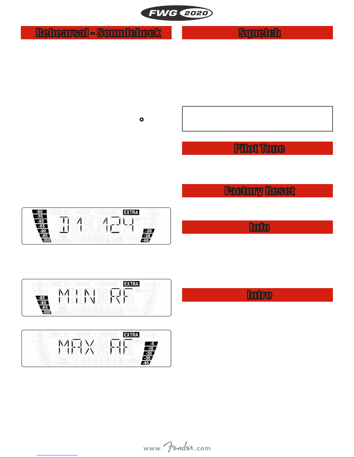
Powering up the Receiver
i Refer to g. 1 on page iii.
1. Press the front panel POWER key to switch power to the receiver
ON. The display will indicate the currently active frequency and
the “LOCK” label. The receiver is in LOCK mode.
If power to the transmitter is OFF or the RF level at the antennas is
zero for some other reason (e.g., shadow eects), the red RF MUTE
LED will be lit and the audio output will be muted. If the antennas
receive RF signal, the green RF OK LED will be lit, the RF bar-graph
will indicate the eld strength of the signal received by the active
antenna, and the Diversity LEDs will indicate which antenna is currently active. The audio bar-graph indicates the audio level of the
received signal. The red AF CLIP LED will ash to indicate audio
signal clipping.
2. If you have assigned a NAME to the receiver, powering the receiver
up will cause the display to indicate the current frequency setting
for 2 seconds and then change to the assigned name.
Powering the Transmitters
SILENT Mode
We recommend setting the carrier frequency in SILENT mode only
(radio transmission OFF).
• To engage SILENT mode, push the ON/OFF switch to “OFF” and
then to its center position. This is the only way to make sure you
won’t go “on air” on a frequency that is not allocated or coordinated and risk “jamming” or interfering with some other RF device or
wireless system.
Selecting Battery Type
1. Switch power to the receiver on.
• You can power the bodypack transmitter with a standard AA size
alkaline battery (LR6), an AA size lithium battery (FR6), or a 1.2 V
rechargeable battery with a capacity of 2100 mAh or higher. If you
are using a new or a fully charged rechargeable battery the transmitter automatically identies the type of battery and displays
the minimal remaining capacity in hours. Approximately 1 hour
before the battery will be dead the “LOW BAT” warning appears at
the receiver and the back-lighting turns red.
5

• The display on your bodypack transmitter indicates
the minimum remaining battery capacity in transmitter
i
ENGLISH
• To ensure an accurate readout, do not use any batteries other
- AA size (FR6) lithium batteries,
or
- High quality AA size NiMH rechargeable batteries with a capaci-
operating hours.
than new, high quality AA size (LR6) alkaline dry batteries from
Duracell or Energizer,
ty of 2100 mAh or higher.
Muting the Transmitter
i Refer to g. 4 on page iv.
1. Set the ON-MUTE/PRG-OFF switch to “MUTE/PRG” (center position). The display indicates the frequency in MHz, the frequency in
Preset form, and “PRG IR”, and subsequently changes to alternating between the currently selected Preset and “PRG IR”.
• If you switched from “OFF” to “MUTE/PRG”: The transmitter audio
and RF sections are OFF and the status LED is dark.
• If you switched from “ON” to “MUTE/PRG”: The transmitter is
muted and the status LED (20) will change from green to red. The
RF section continues transmitting the carrier frequency.
2. To switch the transmitter back on, set the ON-MUTE/PRG-OFF
switch to “ON”. The status LED changes to green and the display
indicates the remaining battery capacity in hours.
System Adjustments
In SETUP mode, the electronic lock is disabled so you can adjust all
receiver parameters. The “LOCK” label is not shown.
3. If the receiver has found enough CHANNELs for your system, conrm the selected GROUP. If the clean CHANNELs found are fewer
than required, use the arrow keys to select a dierent GROUP.
4. Having selected and conrmed a GROUP, you can use the arrow
keys to select any CHANNEL within this GROUP.
5. Select the CHANNEL to which you wish to program a transmitter.
6. Program the assigned transmitter referring to the section on
“Programming Transmitters”.
7. Multichannel systems: Repeat steps 5 and 6 above for each transmission channel.
If the receiver nds no clean frequencies:
i
-86 dBm. Make sure never to set the squelch threshold any higher
than absolutely necessar y. The higher the squelch threshold (-86 dB
= max., -100 dB = min.), the lower the sensitivity of the receiver and
thus the usable range between transmitter and receiver.
• Check the antenna system.
• Slowly increase the squelch threshold from -100 dBm to
Manual Group/Channel
Setup
1. Select the “GROUP/CHANNEL” menu. The currently active GROUP
starts ashing.
2. Conrm the selected GROUP or use the arrow keys to select a different GROUP.
3. Having selected and conrmed a GROUP, you can use the arrow
keys to select any CHANNEL within this GROUP.
4. Select a CHANNEL to which you wish to program a transmitter.
5. Program the assigned transmitter referring to the section on
“Programming Transmitters”.
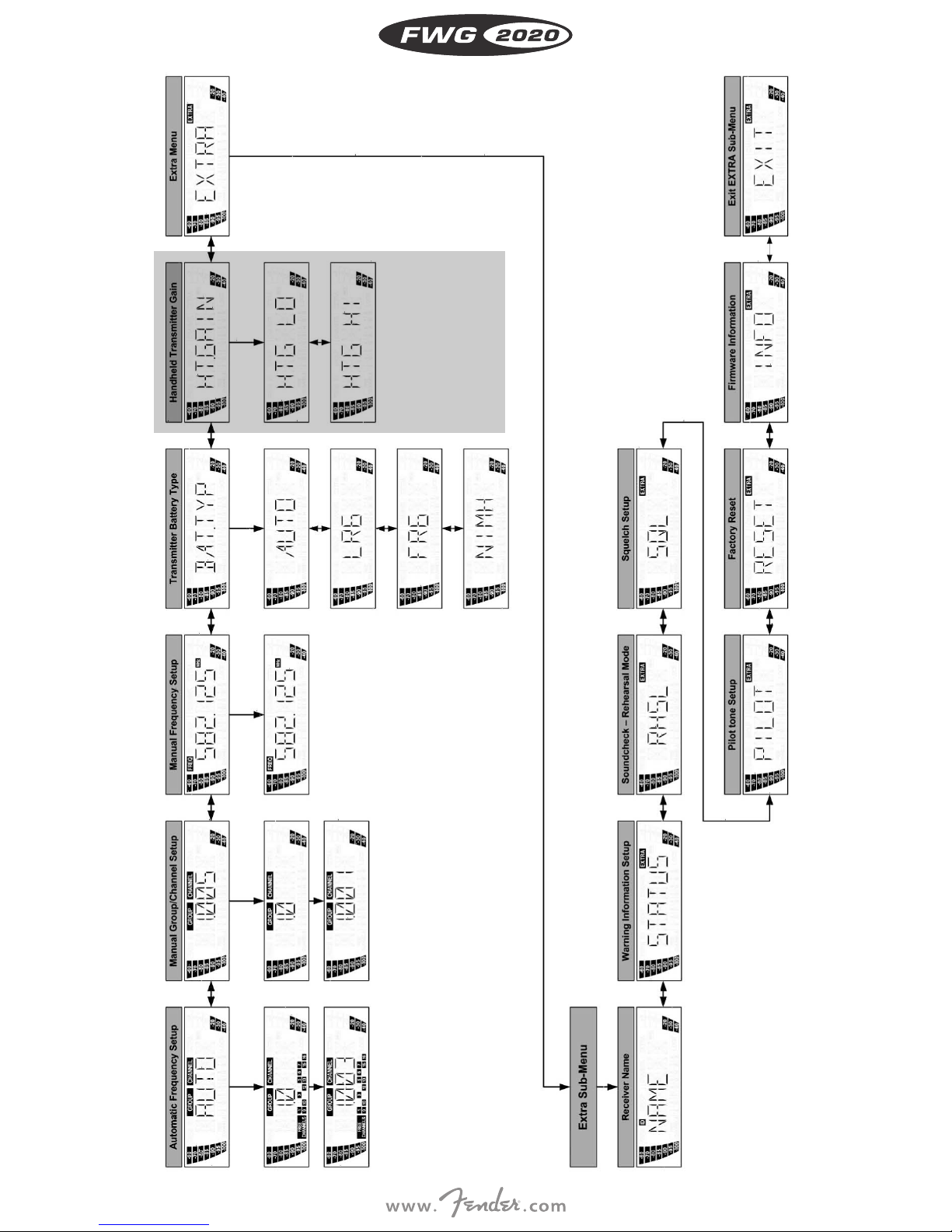
i Refer to the diagram on page ii.
The following setup screens are available:
- Automatic setup
- Manual Group/Channel setup
- Manual frequency selection
- Handheld transmitter gain (NOT USED)
- Advanced functions (EXTRA menu)
• Start by nding a clean frequency. Clean frequencies are frequencies where the receiver nds no RF signal or an RF signal whose
level is lower than the current threshold setting.
Automatic Setup
(Multichannel Systems)
1. Switch all transmitters OFF.
2. Select the “AUTO” menu to start the automatic frequency search.
• The currently active frequency GROUP starts ashing. The receiver scans all preset frequencies (CHANNELS) within the selected
GR OU P.
• The “FREE CHANNELS” eld lists all clean channels.
Setting Frequencies
Manually
1. Select the “FREQUENCY” menu. The currently active frequency
starts ashing.
2. Conrm the selected frequency or use the arrow keys to select a
dierent GROUP.
3. Conrm the selected frequency so you can program the transmitter assigned to the selected frequency.
4. Program the assigned transmitter referring to the section on
“Programming Transmitters”.
6

Programming Transmitters
To program the transmitter to the frequency of the receiver:
1. Switch power to the receiver ON and select a clean frequency or
GROUP/CHANNEL on the receiver. The “PRG IR” menu appears on
the display:
i Refer to g. 4 on page iv.
2. Set the ON-MUTE/PRG-OFF switch (19) to “MUTE/PRG”. The display
will alternately indicate the currently selected frequency and “PRG IR”.
“FR6” for AA size (FR6) lithium batteries. The display indicates
this battery type and its remaining capacity in hours like this: “F
10h” (example). Lithium batteries have a life of up to 14 hours. The
display, however, will only indicate a maximum of 10 hours. With
new lithium batteries, the display will constantly indicate “F 10h”
during the rst four operating hours.
“NiMH” for AA size (HR6) NiMH rechargeable batteries. The dis-
play indicates this battery type and its remaining capacity in hours
like this: “H 6h” (example).
3. Program the assigned transmitter referring to the section on
“Programming Transmitters”.
Since the chemical parameters of batteries take some
time to stabilize, the system may correct the battery
i
indication (type and remaining capacity) about 10 to 30
minutes after switching power to the transmitter on.
ENGLISH
i Refer to g. 11 on page v.
3. Point the infrared sensor (1) on the transmitter at the infrared emitter (2) on the receiver from a distance of 4 inches (10 cm) max.
4. On the receiver, select “IR PRG” to start the programming process.
IR OK: The transmitter has been tuned to the same frequency as
the receiver.
IR ERR: The data transmission has failed (no communication).
TXBAND: The frequency bands of the transmitter and receiver are
not identical.
Multichannel Systems
• Be sure to assign a separate carrier frequency to each wireless
channel (transmitter and receiver).
• To nd inter-modulation-free carrier frequencies quickly and easily, we recommend using the “AUTO” menu to select all required
carrier frequencies from the same Frequency Group.
• Do not operate two or more wireless channels on the same frequency at the same time and location. This would cause unwanted
noise due to radio interference.
Battery Management
To make sure the transmitter battery capacity is indicated correctly:
• Do not use any dry or rechargeable batteries other than the types
listed below.
• Never use batteries that have been in use during the previous 24
hours.
• Match the transmitter system to the type of battery you inserted:
1. Select the “BAT.TYP” menu. The current setting starts ashing.
2. Use the arrow keys to select the desired setting:
“AUTO”: The transmitter automatically identies the battery type.
Weak or very old batteries may cause the remaining battery life
to be displayed incorrectly. In this case, use the correct setting for
your battery (see below):
“LR6” for AA size (LR6) alkaline dry batteries. The display indicates
this battery type and its remaining capacity in hours like this: “L
5h” (example).
4. ADVANCED FUNCTIONS
(EXTRA MENU)
The EXTRA menu provides the following functions:
NAME receiver ID
STATUS status and warning messages
RHSL rehearsal function for nding dropouts
SQL squelch threshold
PILOT pilot tone
RESET default settings
INFO system information screens
EXIT quit sub-menu
Receiver ID
The “NAME” screen lets you edit the existing name of the receiver.
If you have not stored a receiver name yet, you can use the “NAME”
screen to assign a new name to your receiver. The receiver name may
be any combination of up to six letters and/or numbers.
1. Select the “NAME” menu. The rst character start ashing.
2. Use the arrow keys to select the desired characters.
Status and Warning
Messages
The “STATUS” screen lets you activate a visual warning that alerts you
to selectable critical system conditions. If one of the selected conditions occurs, the display back-lighting will change from green to red
and a warning message will appear on the display that describes the
current condition. The warning messages appear in order of priority:
1. “LOW. BAT”: Transmitter battery capacity is low. The battery will
be dead in about 60 minutes.
2. “AF CLIP”: Audio overload. The received audio signal drives the
receiver into clipping.
3. “RF.LOW”: Received signal eld strength is so low that the receiv-
er audio output has been muted to suppress unwanted noise.
All selected warning functions are active in both LOCK and SETUP modes.
7
Rehearsal - Soundcheck
Squelch
The REHEARSAL function detects a maximum of six dropouts and
records the time each dropout occurred, the minimum eld strength
at each antenna, and the maximum audio level. You can view the list
of results after the recording has stopped.
1. From the “RHSL” screen on the receiver, select “START” to start the
ENGLISH
recording.
2. Move the transmitter around the area where you will use the system to check the area for “dead spots”, i.e., places where the eld
strength seems to drop and reception deteriorates.
3. Play a few bars on your instrument (the louder the better).
4. You can stop the recording at any time by pressing l briey.
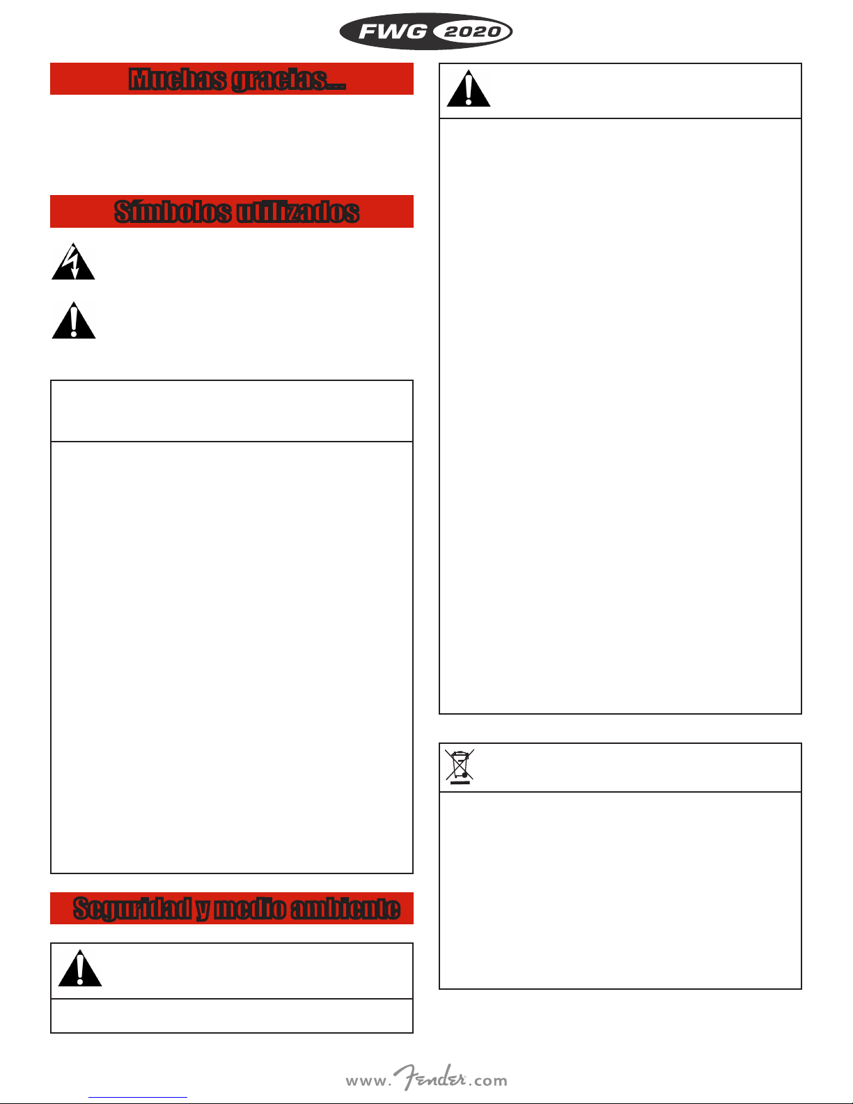
Possible indications:
“D1”: The recording has been completed, the display indicates
dropout no. 1.
“MIN RF”: The recording has been completed, no dropout has
been detected. The display indicates the minimum RF level
measured.
“OVFL”: The recording has been stopped automatically because
six dropouts have been detected already or because the available
time (16 minutes) has elapsed.
• To retrieve the other results press t or u briey. Dropouts are
indicated like this (Example1):
• If the receiver nds no clean frequency, check your antenna setup
(cable lengths, booster, power splitter, system wiring).
• If this is correct and there is still a stable RF noise oor you can try
to increase the squelch threshold slowly from -100 dBm to -86 dBm
to avoid noise when the RF signal is weak. Make sure never to set
the squelch threshold any higher than absolutely necessary. The
adjustable squelch will mute the receiver if the received signal is
too weak so the related noise or the self-noise of the receiver will
not become audible while the transmitter is o the air.
The higher the squelch threshold (-86 dB = max., -100 dB
= min.), the lower the sensitivity of the receiver and thus
i
the usable range between transmitter and receiver.
Pilot Tone
As long as this function is active, the received signal contains a continuous signal at a predened frequency (a pilot tone). If the receiver
detects no pilot tone, the receiver’s audio output will be muted.
Factory Reset
• To reset all parameters to their factory default settings, use the
“FACTORY RESET” screen.
Example 1: Dropout no. 1 occurred after 124 seconds.
• The rst s torage locations are assigned to dropouts, the last two for
the lowest RF level and highest audio level measured (Examples 2
and 3).
Example 2: Minimum RF level: -85 dB
Example 3: Maximum audio level: -5 dB
• The last item in the result list is followed (the rst item preceded)
by the “EXIT” option.
• You can avoid dropouts by placing the receiver or antennas in different positions.
• If the RF bar is o and the RF MUTE LED is red, no signal is being
received or the squelch threshold is too high.
Info
The INFO screen lets you call up information about your receiver:
- ”V1.1”: rmware version
- “B 4--.50”: frequency band
- “PV 1.0”: Preset version
- “INTRO”: This screen allows you to edit the name displayed upon
switching power to the receiver ON.
Intro
The “INTRO” sub-menu lets you enter and save a new name at any
time. You can select any combination of up to 16 letters and numerals.
1. Select the “INTRO” screen. The rst character starts ashing.
2. Use the arrow keys to select the desired characters.
8

Troubleshooting
PROBLEM POSSIBLE CAUSE REMEDY
No sound 1. AC adapte r is not connecte d to receiver and/or power o utlet.
Noise, crackling, unwanted signals. 1. Antenna location.
Distortion. 1. GAIN con trol on transmit ter is set too high or t oo low.
Momentary loss of sound (“dropouts” ) at some points wi thin performance area.
2. Recei ver is OFF.
3. Recei ver is not connect ed to mixer or amplie r.
4. Inst rument is not conne cted to bodypa ck transmitter.
5. Transmit ter is tuned to di erent frequenc y than receiver.
6. Transmit ter is “OFF” or transm itter MUTE switc h at “MUTE”.
7. Transmitter batteries are not inserted properly.
8. Transmitter batteries/bat tery pack dead.
9. Transmit ter is too far away fr om receiver or sque lch threshold set ting is too high.
10. Obstr uctions bet ween transmitt er and receiver.
11. Receiver is invisible from transmitter location.
12. Receiver t oo close to metal obj ects.
13. Transmitt er and receiver Pres et versions are not i dentical.
2. Interference from other wireless systems, TV, radio, CB radios, or defective electrical appliances or installations.
2. Interference from other wireless systems, TV, radio, CB radios, or defective electrical appliances or installations.
• Antenna location. • Reloca te receiver or antenna s. If dead spots per sist, mark and avoi d them.
1. Conne ct AC adapter to recei ver and/or power outle t.
2. Push POW ER switch to switc h receiver ON.
3. Conne ct receiver out put to mixer or ampli er input.
4. Conne ct instrumen t to audio input on bod ypack.
5. Tune trans mitter and recei ver to the same freq uency.
6. Switch t ransmitter “ON ” or set MUTE switch t o ”ON” position.
7. Inse rt batterie s conforming to “+” and “-” marks.
8. Replace batteries/charge batter y pack.
9. Move cl oser to receiver or ch oose lower squelc h threshold set ting.
10. Remove obs tructions.
11. Avoid spots where you cannot see receiver.
12. Remove oe nding object s or move receiver away.
13. Check Pre set versions on t ransmitter and re ceiver.
1. Relo cate receiver or ante nnas.
2. Switch o interference s ources or defec tive appliances o r tune transmit ter
and receiv er to a dierent fre quency; have elec trical inst allation checked .
1. Dec rease or increase G AIN setting jus t enough to stop the d istortion.
2. Switch o interference s ources or defec tive appliances o r tune transmit ter
and receiv er to a dierent fre quency; have elec trical inst allation checked .
ENGLISH
ERROR MESSAGES PROBLEM REMEDY
ER R. >SYS < • Frequency settings cannot be changed. 1. Switch p ower to receiver OFF an d back ON after abo ut 10 seconds.
ERR.>PRE< • Error in s elected Pres et. 1. Conti nue with previous P reset.
RECEIVER ONLY
TXBand 1. Transmit ter frequenc y band is not identi cal with receiver
ERR .>USR< • Las t setting cann ot be loaded. 1. Set frequency and squelch threshold again.
ERR.>RF< • PLL error. (Re ceiver cannot lock o n to selected fr equency.) 1. Set dierent frequency.
TRANSMITTER
RECEIVER AND
Err. >IR< • Infrared transmisison failed. • Point tra nsmitter infr ared sensor dire ctly at receiver i nfrared emit ter from a distanc e of approx. 2
>-h< 1. Transmit ter cannot ident ify batter y as dry or recha rgeable
ONLY
>ChArGE<
TRANSMITTER
(rechargeable battery only)
frequency band.
2. RF out put too high/low.
type.
2. Transmit ter was switche d on during chargin g.
• Batte ry is not fully cha rged. 1. Charg e transmitter u sing charger.
2. If pro blem persist s, contact your Fen der Service Cente r.
2. Select error-free Preset.
3. If problem occurs frequently, contact your Fender Service Center.
1. Use tr ansmitter with t he same frequen cy band as the rece iver.
2. Use tr ansmitter with l ower/higher Rf outp ut.
2. If problem occurs frequently, contact your Fender Service Center.
2. If pro blem persist s, contact your Fen der Service Cente r.
inc hes (5 cm).
1. Remove b attery and rei nsert after a pprox. ve second s.
2. Remove t ransmitter f rom charger, switch o, an d restart char ging
2. Repla ce transmitter b attery with ne w dry or fully cha rged rechargeab le battery.
9

ENGLISH
Specifications
SYSTEM RF CARRIER FREQUENCY RANGES
Ba nd 1: 650.1 – 680 MHz
Ban d 7: 500.1 – 530.5 MHz
Band 9 -U: 600 – 630.5 MHz
Band M: 826.3 – 831.9 MHz
RECEIVER
Switching bandwidth: 30.5 MHz (depending on local regulations)
Modulation: FM
Sensitivity: 6 dBμV / -100 dBm
Receiver type: Super heterodyne
Diversity system: µC contro lled space diversi ty
Audio bandwidth: 35 to 20,000 Hz
THD at 1 kHz: <0.3%
Signal-to-noise: 120 d B(A)
Audio outputs: balanced X LR, switchable to -30 or 0 dB m
unbalance d TS 1/4 ” jack
Audio output level: +9 dBu (max.)
Antenna inputs: 2x 50-ohm BNC female connec tors
Transmitter battery indication: low batter y
Power supply: 12 V / 500 mA DC
Dimensions: 200 x 44 x 190 mm (7.8 x 1.7 x 7.4 in.)
Weight : 972 g (2. 2 lbs.)
BODYPACK TRANSMITTER
Switching bandwidth: 30.5 MHz (depending on local regulations)
Modulation: FM
RF output power: 10, 30 or 50 mW (ERP max., depen ding on local regu lations)
Spurious: ≤ 70 dBc
Antenna: ¼ - wave antenna
Audio bandwidth: 35 to 20,000 Hz
THD at 1 kHz: <0.7% typic al at rated deviatio n/1 kHz
S/N Ratio (A-weighted): 120 d B(A)
Audio input: TB3M 3-pin mini XLR s ocket (3.1 Vrms max.)
Battery lif e: ≥ 7 ho urs (1x LR6 AA-size batt ery)
Size: 60 x 73,5 x 30 mm (2.4 x 2.9 x 1.2 in.)
Net weight: 90 g (3.2 oz.)
≥ 8 hours (1x AA-si ze NiMH >2100 m Ah rechargeable b attery)
≥ 14 hours (1x FR6 AA-siz e lithium batter y)
10
Muchas gracias...
...por adquirir un producto Fender. Este manual contiene instrucciones importantes para la instalación y el manejo de su equipo. Le
rogamos dedique unos minutos a leer con detenimiento las siguientes
instrucciones antes de manejar el equipo. Conserve el manual para
futuras consultas. ¡Deseamos que disfrute utilizando su sistema!
Símbolos utilizados
El símbolo de rayo dentro de un triángulo signica que
existen tensiones peligrosas en el equipo.
El signo de exclamación dentro de un triángulo en el equi-
po indica que el usuario debe consultar el manual de usuario. En el manual de usuario, este símbolo identica las
instrucciones que debe seguir el usuario para garantizar
el funcionamiento seguro del equipo.
Nota importante
i
• El transmisor de bolsillo le indican en el visualizador el tiempo
• Para garantizar una visualización precisa, rogamos utilizar exclu-
- pilas de litio del tipo AA (FR6)
o bien
- acumuladores de primera calidad del tipo AA NiMH con una
- En el menú “BAT.TYP”, seleccione el tipo de pila utilizado (“LR6”,
- Si la pila está muy gastada o el acumulador está muy viejo, es
• Debido a que los parámetros de las pilas no se estabilizan de
• Aunque las pilas de litio pueden alcanzar hasta las 14 horas de
Pila
restante mínimo de funcionamiento del transmisor en horas.
sivamente pilas alcalinas nuevas de primera calidad del tipo AA
(LR6) de Duracell o Energizar,
capacidad de por lo menos 2100 mAh.
“FR6”, “HR6” (NiMH)) o la detección automática de la pila (“AUTO”).
posible que en el modo automático se produzcan imprecisiones
en la indicación del tiempo restante de funcionamiento. Si ello
sucede, seleccione el tipo de pila manualmente.
manera inmediata, es posible que el sistema corrija la información visualizada (tipo de pila y tiempo restante de funcionamiento) después de entre 10 y 30 minutos de funcionamiento.
funcionamiento, en la pantalla del transmisor no se mostrarán
más de, como máximo, 10 horas. Cuando se montan una pila de
litio nueva, durante las 4 primeras horas en la pantalla se muestra
permanentemente “10h”.
Seguridad y medio ambiente
Seguridad
• No exponga el equipo a la radiación solar directa, a un polvo excesivo, humedad, lluvia, vibraciones mecánicas ni golpes.
Seguridad
• No derrame líquido alguno sobre el equipo ni deje caer ningún objeto a través de las ranuras de ventilación del mismo.
• El equipo puede utilizarse únicamente en estancias secas.
• Antes de utilizar el equipo, verique que la tensión de servicio corresponda a la tensión de red en el lugar de utilización.
• Utilice el equipo solamente con el alimentador de red de tensión
alterna con tensión de salida de 12 V CC. ¡Otros tipos de corriente
pueden dañar seriamente el aparato!
• El equipo debe abrirse, someterse a mantenimiento y repararse exclusivamente por personal autorizado. El equipo no contiene componentes cuyo mantenimiento pueda realizarse por el usuario.
• Antes de conectar el equipo a la alimentación eléctrica, compruebe
que la tensión de red CA indicada en el equipo coincida con la tensión de red CA disponible en el lugar donde vaya a utilizar el equipo.
• Utilice el equipo únicamente con tensiones de 90 a 240 VCA. ¡En caso
de utilizar una tensión de red CA diferente, la unidad podría sufrir
graves daños!
• Si cualquier objeto sólido o líquido penetrara en el equipo, desconecte de inmediato el sistema de sonido. Desconecte inmediatamente el cable de alimentación eléctrica de la salida y encargue la
comprobación del equipo al personal de mantenimiento de Fender.
• No coloque el equipo en las inmediaciones de fuentes de calor como
radiadores, tubos de calefacción, amplicadores, etc. y no lo exponga a la radiación solar directa, a un polvo excesivo, humedad, lluvia,
vibraciones mecánicas ni golpes.
• Para evitar zumbidos o interferencias, tienda todos los cables de
audio, en especial aquellos conectados a las entradas, alejados de
todo tipo de cables eléctricos. Si utiliza tubos para cables o canales,
asegúrese de utilizar unos independientes para los cables de audio.
• Limpie el equipo utilizando únicamente un paño húmedo (no mojado). ¡Asegúrese de desconectar el equipo de la red CA antes de limpiar el equipo! No emplee nunca productos de limpieza ácidos o corrosivos ni productos que contengan alcohol o disolventes puesto que
pueden provocar daños en los componentes barnizados y plásticos.
• Utilice el equipo exclusivamente para las aplicaciones descritas en el
presente manual. Fender no se responsabilizará de forma alguna por
daños derivados del uso incorrecto o indebido del equipo.
Medio ambiente
• Asegúrese de eliminar las pilas usadas según la normativa local
de eliminación de residuos. No tire nunca las pilas al fuego (riesgo
de explosión) ni a la basura común.
• El embalaje del equipo es reciclable. Coloque el embalaje en un
contenedor adecuado puesto a disposición por la administración
local responsable de la recolección y reciclaje de residuos y cumpla todas las normativas locales en material de eliminación y reciclaje de residuos.
• Al eliminar el equipo, extraiga las pilas, separe la carcasa, las tarjetas de circuitos y los cables y elimine todos los componentes
según las normativas locales en material de eliminación de residuos.
ESPAÑOL
11
1. GENERALIDADES
Introducción
El sistema inalámbrico está compuesto de un receptor Diversity estacionario y el transmisor de bolsillo. Receptor y transmisor funcionan
en una sub-banda de máx. 30 MHz (por conjunto de frecuencias) en
la gama de frecuencia portadora UHF de 500 MHz hasta 865 MHz.
Dentro de esta sub-banda se puede elegir la frecuencia receptora
de entre los grupos de frecuencias y subcanales preprogramados del
receptor o programarla directamente en pasos de 25 kHz. El transmisor bolsillo son ajustados a los parámetros seleccionados para el
receptor por infrarrojo.
ESPAÑOL
Accesorios/piezas
Número de pieza Pieza
7704710000 PASSIVE DIRECTIONAL ANTENNA
7744711000 ACTIVE DIRECTIONAL ANTENNA
7704712000 PASSIVE WD-BND OMNIDIRECTIONAL ANTENNA
7704713000 ACTIVE WD-BND OMNIDIRECTIONAL ANTENNA
7704714000 POWER SW SUPPLY 12V 500 MA MULTIPLUG
7704715000 BODY PACK TRANSMITTER CHARGING STATION
7704716000 PT 2020 WIRELESS BODY PACK TRANSMITTER
7704717000 FMKPS ANTENNA CABLE 2 FT 65 CM
7704718000 FMKA5 ANTENNA CABLE 16 FT 5 M
7704719000 FMKA20 ANTENNA CABLE 66 FT 20 M
7704720000 FRONT MOUNT ANTENNA RACKMOUNT KIT
7704722000 ITC3 INSTRUMENT TRANSMITTER CABLE 3 FT
Receptor
Placa frontal
i Véase Fig. 1 en la página iii.
1 POWER: interruptor con-des.
2 Display LC: el receptor dispone de un display LC con iluminación
de fondo.
c Parámetro, modo de operación ajustable
d Barra audio para indicar el nivel audio recibido
e Símbolo “LOCK”
f Cabakes disponibles (para la regulación automática de la
frecuencia)
• Cuando están activadas una o más funciones de aviso, el dis-
play se ilumina de rojo si se ha producido una condición crítica. Mientras se encuentren en sus gamas normales todos los
parámetros, el display se ilumina de verde.
3 t l u : estas tres teclas regulan los distintos parámetros del
receptor.
• En el modo LOCK:
Pulsar brevemente t ó u : conmutar entre indicación de fre-
cuencia, indicación de preajuste e indicación del nombre del
receptor.
Pulsar prolongadamente l : conmutar el receptor para el
modo SETUP.
• Sólo en el modo SETUP:
Pulsar brevemente l : extraer el parámetro a ser ajustado o
conrmar el valor ajustado.
Pulsar prolongadamente l : conmutar el receptor para el
modo LOCK.
Pulsar brevemente t : seleccionar un punto del menú o redu-
cir el valor a ser ajustado.
Pulsar brevemente u : seleccionar un punto del menú o
aumentar el valor a ser ajustado.
4,5 LEDs RF: cuando el receptor recibe una señal RF se ilumina el LED
OK verde (4), cuando no se recibe ninguna señal RF, se ilumina el
LED MUTE rojo (5).
6 LEDs Diversity A y B: estos dos LEDs indican con su iluminación
cuál antena está activada.
7 LEDs AF: estes LEDs indican el nivel audio recibido:
OK (verde): -40 dB hasta +3 dB
CLIP (rojo): >3 dB (sobremodulación)
8 Diodo transmisor infrarrojo: transmite la frecuencia regulada en
el receptor al transmisor de bolsillo. El diodo transmisor infrarrojo
tiene un ángulo de emisión muy estrecho (aprox. 10°) y un alcance
de máx. 20 cm para impedir que haya más de un transmisor ajustado a la misma frecuencia.
9 Regulador de nivel de salida: con este control giratorio retráctil
se puede atenuar el nivel de la salida audio balanceada sin graduación en 0 hasta 30 dB.
El display indica todos los parámetros del receptor:
a Barra de RF para indicar la intensidad de campo de la señal de
recepción
b Indicación alfanumérica del valor actual ajustado
12
Placa posterior
i Véase Fig. 2 en la página iii.
10 DC IN: toma de corriente atornillable para la conexión del alimen-
tador de red suministrado.
11 ANTENNA A/B: tomas BNC para la conexión de las dos antenas
URF suministradas (11a) o de antenas espaciadas opcionales.
12 BALANCED: salida audio balanceada en una toma XLR de 3 polos.
Esta salida la puede conectar, por ejemplo, a la salida de un pupitre de mezcla.
13 UNBALANCED: salida audio no balanceada en un jack mono de 6,3
mm. Aquí puede conectar, por ejemplo, un amplicador de guitarra.
14 Conmutador de nivel de salida: conmutador corredizo para
ajustar el nivel de salida de la toma BALANCED a la sensibilidad de
entrada del aparato conectado. El conmutador tiene dos graduaciones: 0 y -30 dB. El regulador de nivel de salida (8) permite obtener una atenuación adicional del nivel salida hasta -60 dB. El nivel
de la salida UNBALANCED no se puede regular.
15 Placa indicadora de tipo con la gama de frecuencias portadoras
y las informaciones de autorización.
Transmisor de bolsillo
29 Heb illa de cinturón para sujetar el transmisor de bolsillo en el cinturón.
30 Toma MUTE: conexión para la clavija terminal suministrada para
bloquear el interruptor ON-MUTE/PRG-OFF para evitar fallos de
manejo.
31 Regulador de sensibilidad: con este control giratorio en el com-
partimiento de pilas puede ajustar la sensibilidad de entrada del
transmisor de bolsillo al instrumento conectados.
2. PUESTA EN SERVICIO
i Véase Fig 4 en la página iv.
17 Diodo receptor infrarrojo: recibe la señal infrarroja del receptor
para la regulación automática de la frecuencia portadora.
18 Display LC: indica la frecuencia ajustada en MHz o como prea-
juste, indicaciones de fallos y la capacidad de las pilas en horas
(para funcionamiento con pilas en pasos de 1 hora, para funcionamiento con acumuladores en pasos de 2 horas).
19 ON-MUTE/PRG-OFF: conmutador corredizo con tres posiciones:
ON: la señal de salida de la cápsula microfónica es transmitida al
transmisor y éste transmite la señal audio al receptor (régimen
normal). El LED de control (20) se ilumina de verde.
MUTE/PRG: la señal audio está en mudo. Si pone el conmutador
a “MUTE/PRG”, el transmisor está en modo de programación. Para
volver a conectar la señal audio, corra el control a la posición “ON”.
OFF: el suministro de corriente del transmisor está desconectado.
20 LED de control: este LED bicolor indica los regímenes siguientes:
Verde: la capacidad de la pila es de más de una hora, el transmisor
funciona en régimen normal.
Rojo: la capacidad restante de la pila es de menos de una hora, y/o
la señal audio está en mudo.
Centelleante de rojo: aviso de error en el display.
Desconexión: el suministro de corriente del transmisor está
desconectado o bien el transmisor se encuentra en modo de
programación.
22 Compartimiento de pilas para la pila de 1,5 V tamaño AA sumin-
istrada o un acumulador, corriente en el comercio, de 1,2 V, ≥2100
mAh, tamaño AA.
25 Antena: antena ja exible.
26 Entrada audio: toma mini-XLR de 3 polos con contactos para los
niveles de línea. Con la asignación de los alleres de los conectores
del cable para instrumentos ITC3, se ocupan automáticamente los
contactos correctos. Con el cable para instrumentos ITC3 suminstrado se puede conectar una guitarra eléctrica, un bajo eléctrico
o un teclado en banderola.
27 Etiqueta adhesiva de frecuencias: en la placa posterior del trans-
misor de bolsillo se encuentra una etiqueta adhesiva que indica la
gama de frecuencias portadoras disponible y las informaciones de
autorización.
28 Compartimiento de pilas para la pila de 1,5 V tamaño AA sumin-
istrada o un acumulador, corriente en el comercio, de 1,2 V, NiMH,
≥2100 mAh, tamaño AA. A través de la mirilla puede controlar en
todo momento si hay una pila o un acumulador en el compartimiento, aunque también puede colocar en la mirilla una tira
blanca para rotular (suministrada) o una tira de color (opcional).
Receptor Montaje en bastidor
• Si instala uno o más receptores en un bastidor de 19”, puede
montar las antenas suministradas en la placa frontal (para lo cual
necesita el juego opcional de montaje para placa frontal) o bien,
utilizar antenas espaciadas. Sólo de esta manera puede garantizar
una calidad de recepción óptima.
Un receptor
i Véase Fig. 6 en la página vi.
1. Destornille las cuatro patas de goma (1) del lado inferior del
receptor.
2. Destornille los dos tornillos de jación (2) de cada una de las dos
paredes laterales.
3. Atornille con los tornillos de jación (2) la escuadra de montaje
corta (3) a una de las paredes laterales y la escuadra de montaje
larga (4) del set de montaje suministrado a la otra pared lateral.
4. Fije el receptor en el rack.
Dos receptores contiguos
i Véase Fig. 7 en la página vi.
1. Destornille las cuatro patas de goma (1) del lado inferior de los
receptores y saque los tornillos (5) de las patas de goma (1).
2. Destornille los dos tornillos de jación (2) de la pared lateral derecha de uno de los receptores y de la pared lateral izquierda del otro
receptor.
3. Pase una pieza de unión (4) a través de cada una de las ranuras
libres de la pared lateral del primer receptor, de modo tal que el
agujero de jación de cada pieza de unión quede alineado con el
correspondiente agujero roscado del lado inferior del receptor.
4. Fije las piezas de unión (4) al primer receptor utilizando los tornillos (5) que sacó de las patas de goma.
5. Una ambos receptores pasando las piezas de unión (4) del primer
receptor a través de las ranuras libres de la pared lateral del segundo receptor de modo tal que el agujero de jación de todas las
piezas de unión (4) queden alineados con el correspondiente agujero roscado del lado inferior del segundo receptor.
6. Fije las piezas de unión (4) al segundo receptor utilizando los tornillos (5) que sacó de las patas de goma (1). Atornille una escuadra
de montaje corta 6 a la pared lateral exterior de cada uno de los
receptores utilizando para cada escuadra dos de los tornillos (2)
que sacó de las paredes laterales.
7. Fije los receptores en el rack.
ESPAÑOL
13
Conexión de las antenas
Las antenas de ¼ de onda suministradas pueden montarse rápida y
fácilmente y son aptas para aplicaciones en las que se dispone de un
ángulo visual directo entre el transmisor y la antena del receptor y
donde desee emplearse un sistema inalámbricos sin necesidad de un
arduo trabajo de instalación.
Antenas remotas
• Debe utilizar antenas de montaje remoto en el caso de que la
posición del receptor no permita una buena recepción.:
- Conecte las antenas remotas en los conectores BNC situados en la
parte posterior del receptor
ESPAÑOL
- Utilice cables RG58 ó RG213 para conectar las antenas.
Cable de montaje frontal para antena
• Utilice el cable de extensión BNC (Front Mount Antenna Rack
Mount Kit P/N 7704720000) para montar las antenas de ¼ de onda
en el panel frontal.
Ubicación del receptor
• El conmutador del nivel de salida permite adaptar el nivel de la
salida balanceada (BALANCED) a la sensibilidad de entrada del
aparato conectado.
• Si se ha conectado el receptor a una entrada de micrófono, seleccione la posición “-30 dB”. De esta forma, el nivel de salida se reducirá
30 dB para evitar que se produzca sobremodulación en la entrada.
• El nivel de la salida no balanceada (UNBALANCED) no se puede
ajustar.
Conexión del receptor a la red
i Véase Fig. 9 en la página iii.
1. ATENCIÓN: Verique que la tensión de alimentación indicada
en el alimentador de red suministrado sea la misma que la disponible en el lugar en el que se usará el receptor. Si usa el alimentador de red con una tensión de alimentación diferente,
puede causar daños al equipo.
2. Conecte el cable de alimentación (1) del alimentador de red suministrado al conector hembra DC IN (2) en la parte trasera del receptor y je el conector macho (3) atornillándolo.
3. Enchufe el adaptador de red en un tomacorriente.
La señal directa del transmisor puede ser debilitada o apagada por
reexiones en partes metálicas, paredes, techos, etc., o por la presencia de músicos u otras personas.
Por lo tanto, debe colocar el receptor o las antenas remotas de la siguiente manera:
• Coloque el receptor/las antenas siempre cerca del área de actuación (escenario), pero asegúrese de que la distancia entre el
receptor/las antenas y el transmisor sea de 3 metros como mínimo.
• El contacto visual entre el transmisor y el receptor/las antenas es el
requisito previo para la óptima recepción.
• Coloque el receptor/las antenas a más de 1,5 metros de distancia
de grandes objetos metálicos, paredes, estructuras del escenario,
techos, etc.
• El receptor puede ser usado en forma independiente o ser instalado en un bastidor de 19”.
• Si instala uno o más receptores en un bastidor de 19”, puede
montar las antenas suministradas en la placa frontal (para lo cual
necesita el juego opcional de montaje para placa frontal) o bien,
utilizar antenas espaciadas. Sólo de esta manera puede garantizar
una calidad de recepción óptima.
Conexión del receptor a un
mezclador o amplificador
Puede conectar la salida XLR y la clavija jack de 6,3 mm en cualquier
momento. A través del menú AUDIO, es posible ajustar el nivel de salida tal y como sea necesario.
• Conecte la salida de audio en la entrada deseada:
- Salida XLR -> cable XLR -> entrada XLR
- Clavija jack de 6,3 mm -> cable jack -> entrada jack de 6,3 mm
Conmutador del nivel de salida
Modo LOCK
El receptor está electrónicamente bloqueado con el n de que no
pueda realizar ajustes inintencionados. En la pantalla se muestra el
símbolo “LOCK”.
• Para entrar en el modo SETUP, pulse y mantenga pulsado el control l hasta que el símbolo “LOCK” desaparezca.
Transmisor de bolsillo
Introducir la pila
i Véase Fig. 5 en las páginas iv.
1. Abra la tapa del compartimiento de pilas (1).
2. Introduzca la pila suminstrada (2) siguiendo los correspondientes
símbolos en el compartimiento de pilas. Si coloca mal la pila, el
transmisor no recibe corriente.
3. Cierre la tapa del compartimiento de pilas (1).
• En lugar de la pila suminstradas puede introducir también una
ppila de litio (FR6) ó un acumulador, corriente en el comercio, de
1,2 V, NiMH (HR6), ≥2100 mAh, tamaño AA.
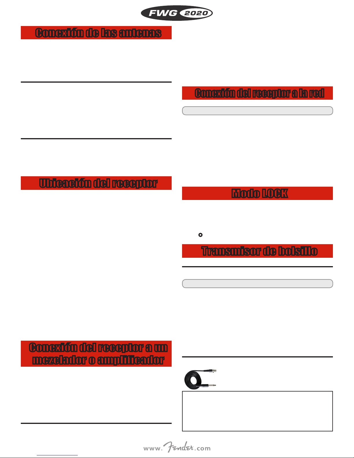
Conectar un instrumento
Utilice sólo el cable de instrumento ITC3 que se
incluye con transmisor bolsillo.
Rogamos tener presente que Fender no puede garan-
tizar un funcionamiento impecable del transmisor de
i
bolsillo con productos de otros fabricantes y que, por lo
tanto, los posibles daños causados por el funcionamiento con esos productos de otros fabricantes quedarán
excluidos de la prestación de garantía.
14
i Véase Fig. 12 en la página iv.
• Conecte el conector mini-XLR (1), que se encuentra en el cable
para instrumento ITC3 (2) a la toma de la entrada audio (3) del
transmisor de bolsillo.
3. INDICACIONES DE MANEJO
Encendido del receptor
Bloquear el interruptor ON-MUTE/PRG-OFF
i Véase Fig. 17 en la página v.
1. Enchufe la clavija terminal (3) suministrada a la toma REMOTE
MUTE (2) del transmisor de bolsillo. El interruptor ON-MUTE/PRGOFF del transmisor de bolsillo queda bloqueado electrónicamente.
El transmisor ya no se puede poner en mudo involuntariamente.
2. Para activar otra vez el interruptor ON-MUTE/PRG-OFF desenchufe la clavija terminal (3) de la toma REMOTE MUTE (2).
Ajuste de la sensibilidad
i Véase Fig. 12 en la página iv.
1. (4) Abra el compartimiento de pilas del transmisor de bolsillo.
2. Toque el instrumento (lo más fuerte posible).
3. (6) Con el destornillador integrado (6) en la tapa de la caja de pilas
(5), ajuste el regulador de sensiblidad (7) de tal forma que la parte
audio del transmisor quede modulada en forma óptima (el LED AF
OK verde está ilumindado, la barra audio indica un máx. de 0 dB).
4. (7) Cierre el compartimiento de pilas.
Modo silencio
Recomendamos ajustar la frecuencia portadora únicamente en el
modo silencio (RF OFF).
• Para activar el modo silencio, pulse y mantenga pulsado el interruptor MUTE mientras conecta el transmisor. Se trata de la única
manera de asegurar que no se va a conectar en directo a una frecuencia que no está asignada o coordinada y de evitar el riesgo de
interferencia con otros dispositivos RF o sistemas inalámbricos.
Seleccionar el tipo de pila
1. Encienda el receptor.
i Véase Fig. 4 en la página iv.
2. Ponga el interruptor ON-MUTE/PRG-OFF (19) del transmisor en
“MUTE/PRG”. El display indica en forma alternada la frecuencia
actual y “PRG IR”.
3. En el menú “BAT.TYP” del receptor, seleccione el tipo de pila utilizado: “LR6”, “FR6”, “HR6” (=NiMH) o “AUTO”.
i Véanse Fig. 10 y Fig. 11 en la página v.
4. Mantenga el diodo receptor infrarrojo (1) del transmisor a una distancia de máximo 10 cm delante del diodo transmisor infrarrojo (2)
del receptor.
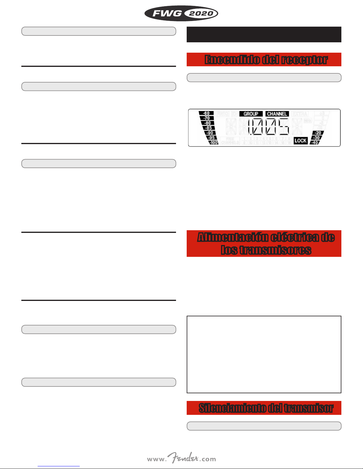
i Véase Fig. 1 en la página iii.
1. Encienda el receptor pulsando la tecla POWER en la placa frontal.
En el display aparece la frecuencia ajustada y el símbolo “LOCK”, es
decir, el receptor se encuentra en el modo LOCK.
Si el transmisor no está encendido o si por otros motivos (p.ej.
eclipsado) el receptor no recibe una señal RF, se ilumina el LED RF
MUTE rojo y la salida audio pasa a mudo. Si se recibe una señal
RF, se ilumina el LED RF OK verde, la barra RF indica la intensidad
de campo de la señal receptora en la antena activada y los LEDs
Diversity indican cuál es la antena activada. La barra audio indica
el nivel audio de la señal recibida. Con sobremodulación se ilumina el LED AF CLIP rojo.
2. Si al receptor le ha asignado un nombre, el display indica, después
de la puesta en marcha, durante aprox. 2 segundos la frecuencia
ajustada y luego, automáticamente, el nombre asignado.
Alimentación eléctrica de
los transmisores
• El transmisor de bolsillo pueden funcionar con una pila alcalina de
tipo LR6, una pila de litio de tipo FR6 o una pila recargable de 1,2
V con una capacidad mínima de 2100 mAh. Cuando se monta una
pila nueva o una pila recargable completamente cargada, el transmisor detect a automáticamente el tipo de pila e indica el tiempo de
reproducción restante en horas en la pantalla. Aproximadamente
1 hora antes de que se agote la pila, en la pantalla se muestra el
aviso “LOW BAT” y la luz de fondo se vuelve de color rojo.
• El transmisor de bolsillo le indican en el visualizador el
tiempo restante mínimo de funcionamiento del transmi-
i
• Para garantizar una visualización precisa, rogamos utilizar exclu-
- pilas de litio del tipo AA (FR6),
o bien
- acumuladores de primera calidad del tipo AA NiMH con una
sor en horas.
sivamente - pilas alcalinas nuevas de primera calidad del tipo AA
(LR6) de Duracell o Energizar,
capacidad de por lo menos 2100 mAh.
Silenciamiento del transmisor
ESPAÑOL
i Véase Fig. 4 en la página iv.
1. Coloque el interruptor ON-MUTE/PRG-OFF en “MUTE/PRG”
(posición central). En la pantalla se visualiza la frecuencia en MHz,
15
 Loading...