

Page 1
FWG
UHF Wireless System™
ENGLISH ESPAÑOL FRANÇAIS ITALIANO DEUTSCHPORTUGUÊS
1010
OWNER’S MANUAL — p. 1
MANUAL DE INSTRUCCIONES — p. 6
MODE D’EMPLOI — p. 11
MANUAL DO PROPRIETÁRIO — p. 16
MANUALE UTENTE — p. 21
BEDIENUNGSHANDBUCH — S. 26
Page 2
FWG
1010
ENGLISH
Symbols Used
The lightning ash with arrow point in an equilateral trian-
gle means that there are dangerous voltages present
within the unit.
The exclamation point in an equilateral triangle on the
equipment indicates that it is necessary for the user to
refer to the User Manual. In the User Manual, this symbol
marks instructions that the user must follow to ensure
safe operation of the equipment.
Safety and Environment
Safety
• Do not spill any liquids on the equipment.
• Do not place any containers containing liquid on the device or
the power pack.
• The equipment may be used in dry rooms only.
• The equipment must only be opened, serviced, and repaired by
authorised personnel. The equipment contains no user-serviceable parts.
• Before connecting the equipment to power, check that the AC
mains voltage stated on the supplied AC adapter is identical to
the AC mains voltage available where you will use the equipment.
• Only operate the equipment with the supplied AC adapter with a
12-VDC output. Using adapters with a dierent output voltage or
current type may cause serious damage to the unit.
• If any solid object or liquid should get into the equipment, shut
down the system immediately. Disconnect the AC adapter from
the power outlet at once and have the equipment checked by
our customer service department.
• If the equipment is not going to be used for a long time, disconnect the AC adapter from the power outlet. Please note that if you
turn the equipment o while leaving the AC adapter plugged in,
it is not fully isolated from the power supply.
• Do not place the equipment near heat sources such as radiators,
heating ducts, ampliers, etc. and do not expose it to direct sunlight, excessive dust, moisture, rain, mechanical vibrations, or
shock.
• To avoid hum or interference, route all audio lines, particularly
those connected to the microphone inputs, away from power
lines of any type. If you use cable ducts, be sure to use separate
ducts for the audio lines.
• Clean the equipment with a moistened (not wet) cloth only. Be
sure to disconnect the AC adapter from the power outlet before
cleaning the equipment. Never use caustic or scouring cleaners
or cleaning products containing alcohol or solvents since these
may damage the enamel and plastic parts.
• Only use the equipment for the applications described in this
manual. Fender cannot accept any liability for damages resulting
from improper handling or misuse.
Environment
• The power supply unit consumes a small amount of electricity
even when the unit is switched o. To save energy, unplug the
power supply unit from the socket if you are not going to be using the unit for some time.
• The packaging is recyclable. Dispose of the packaging in an appropriate recycling collection system.
• If you scrap the unit, separate the case, electronics and cables
and dispose of all the components in accordance with the appropriate waste disposal regulations.
FCC STATEMENT
The transmitter has been tested and found to comply with the
limits for a low-power auxiliary station pursuant to Part 74 of the
FCC Rules. The receiver has been tested and found to comply with
the limits for a Class B digital device, pursuant to Part 15 of the FCC
Rules. These limits are designed to provide reasonable protection
against harmful interference in a residential installation. This equipment generates, uses, and can radiate radio frequency energy and,
if not installed and used in accordance with the instructions, may
cause harmful interference to radio communications. However,
there is no guarantee that interference will not occur in a particular
installation. If this equipment does cause harmful interference to
radio or television reception, which can be determined by turning
the equipment o and on, the user is encouraged to try to correct
the interference by one or more of the following measures:
• Reorient or relocate the receiving antenna.
• Increase the separation between the equipment and the receiver.
• Connect the equipment into an outlet on a circuit dierent from
that to which the receiver is connected.
• Consult the dealer or an experienced radio/TV technician for
help.
Shielded cables and I/O cords must be used for this equipment to
comply with the relevant FCC regulations. Changes or modications not expressly approved in writing by FMIC may void the user’s
authority to operate this equipment.
The receiver complies with Part 15 of the FCC Rules. Operation is
subject to the following two conditions: (1) this device may not
cause harmful interference, and (2) this device must accept any
interference received, including interference that may cause undesired operation.
USA only: FCC CONSUMER ALERT
Most users do not need a license to operate this wireless system.
Nevertheless, operating this system without a license is subject to
certain restrictions: the system may not cause harmful interference;
it must operate at a low power level (not in excess of 50 milliwatts);
and it has no protection from interference received from any other
device.
Purchasers should also be aware that the FCC is currently evaluating
use of wireless systems, and these rules are subject to change. For
more information, call the FCC at 1-888- CALL-FCC (TTY: 1-888-TELLFCC) or visit the FCC’s website at www.fcc.gov/cgb/wirelessmicrophones.
1
Page 3
FWG
1. DESCRIPTION
Introduction
Thank you for purchasing a Fender product. This manual contains
important instructions for setting up and operating your equipment.
Please take a few minutes to read the instructions below carefully
before operating the equipment. Please keep the manual for future
reference. We hope you enjoy using your system!
Accessories/Parts
Part Number Item
7704710000 PASSIVE DIRECTIONAL ANTENNA
7744711000 ACTIVE DIRECTIONAL ANTENNA
7704712000 PASSIVE WD-BND OMNIDIRECTIONAL ANTENNA
7704713000 ACTIVE WD-BND OMNIDIRECTIONAL ANTENNA
7704714000 POWER SW SUPPLY 12V 500 MA MULTIPLUG
7704715000 BODY PACK TRANSMITTER CHARGING STATION
7704721000 PT1010 WIRELESS BODY PACK TRANSMITTER
7704717000 FMKPS ANTENNA CABLE 2 FT 65 CM
7704718000 FMKA5 ANTENNA CABLE 16 FT 5 M
7704719000 FMKA20 ANTENNA CABLE 66 FT 20 M
7704720000 FRONT MOUNT ANTENNA RACKMOUNT KIT
7704722000 ITC3 INSTRUMENT TRANSMITTER CABLE 3 FT
Receiver
The SR1010 is a stationary receiver for all channels of the FWG1010 system. The SR1010 operates in a switching bandwidth of up to 30 MHz
in the UHF carrier frequency range from 530.025 MHz to 931.850 MHz
and can be switched to up to eight dierent carrier frequencies.
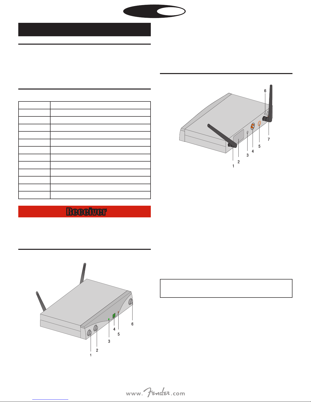
Front Panel
1010
3 RF OK : This LED lights up to indicate that signal is being received. If
no signal is received or the automatic squelch is on, the RF OK LED
goes out and the audio output is muted.
4 Display: Shows the selected receiving channel.
5 CLIP: This LED lights up if the audio level is too high.
6 CHANNEL: This button allows you to select one of up to 8 dierent
carrier frequencies within the receiver’s carrier frequency range.
Rear Panel
1 ANTENNA A/B: BNC jacks for connection of the two supplied UHF
antennas or remote antennas (optional).
2 Carrier frequency label: An adhesive label stating the carrier fre-
quency band is axed on the back of the receiver. The enclosed
frequency chart provides further information about the available
frequencies.
3 SQUELCH: The squelch function turns the receiver o if the
received signal is too weak so that the associated static noise or
inherent noise of the receiver are not audible when the transmit ter
is turned o. Set the SQUELCH control to minimum before turning
the receiver on for the rst time.
4 AUDIO OUT/BALANCED: Symmetric audio output on 3-pole
XLR jack: You can connect the input of a mixer to this output, for
example.
5 AUDIO OUT/UNBALANCED: Asymmetric audio output on 1/4”
(6.3 mm) mono jack. Here you can connect a guitar amplier, for
example.
ENGLISH
1 ON/OFF: Switches power to the unit on or o.
2 VOLUME: This rotary control allows continuous adjustment of the
audio output level.
Using the two output jacks (BALANCED and
i
6 Strain relief for the supply cable of the provided AC adaptor.
7 DC IN: Supply socket for connecting the supplied AC adapter.
UNBALANCED) at the same time may lead to level drops
and increased noise.
2
Page 4
FWG
1010
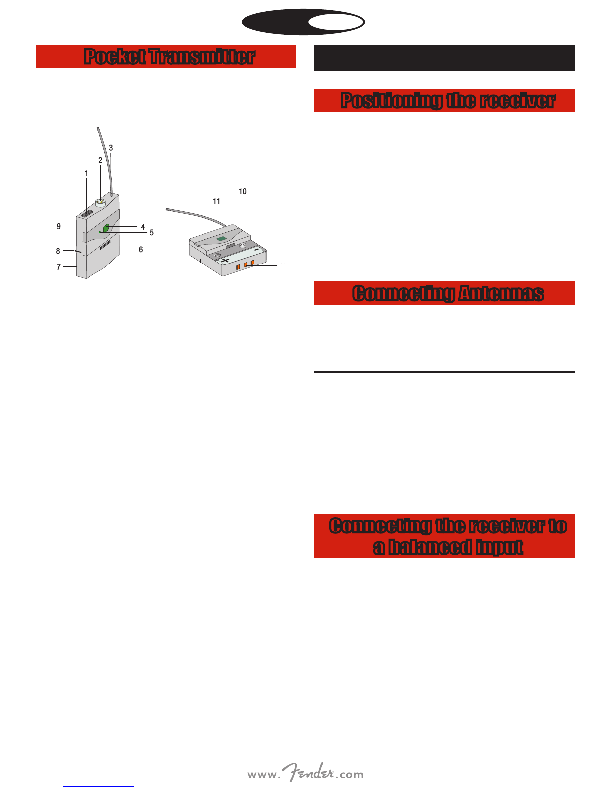
Pocket Transmitter
You can use the pocket transmitter with an electric guitar, electric
bass or keytar. The PT1010 operates within a switching bandwidth of
up to 30 MHz in the 530.025 to 931.850 MHz UHF carrier frequency
range and oers up to 8 selectable carrier frequencies.
ENGLISH
1 ON/OFF switch: This slider has three positions:
ON: The transmitter’s power supply is turned on.
MUTE: The audio signal emitted by the transmitter is muted. The
power supply and HF carrier frequency remain activated.
OFF: The transmitter’s power supply is turned o.
2 Audio input jack: 3-pole mini XLR jack for connection to the sup-
plied ITC3 instrument cable.
3 Antenna: Integrated exible antenna.
4 Display: Shows the set transmission channel.
5 Control LED: This LED indicates the operational availability of the
transmitter.
LED is green: Battery is OK.
LED is red: As soon as the LED changes to red, the remaining bat-
tery power allows at most one more hour of operation (15 minutes for rechargeable batteries). Exchange the batteries as soon
as possible.
6 Battery compartment cover with integrated screwdriver for
adjusting GAIN setting.
7 Inspection window: The inspection window allows you at all
times to check whether a battery or a rechargeable battery is
inserted in the battery compartment.
8 Belt clip: To attach the pocket transmitter to a belt.
9 Carrier frequency label: An adhesive label stating the carri-
er frequency band is axed on the back of the transmitter. The
enclosed frequency chart provides further information about the
available frequencies.
10 CHANNEL: With this button, you can adjust the transmitter to one
of up to eight dierent carrier frequencies within the transmitter’s
carrier frequency band.
11 GAIN: This control serves to adapt the sensitivity of the audio
input to the level of the connected instrument. Adjust using the
screwdriver integrated into the battery compartment cover.
12 Charging contacts: The recessed charging contacts allow you
to charge a battery using the optional charger without having to
remove the battery from the batter y compartment. Turn the transmitter o prior to charging.
2. SETTING UP
Positioning the receiver
• Set up the receiver as a free-standing unit.
• Reections o metal parts, walls, ceilings, etc. or the shadow eects
of musicians and other people may weaken or cancel the direct
transmitter signal.
For best results, set up the receiver as follows:
1) Place the receiver near the performance area (stage). Make sure,
though, that the transmitter will never be any closer to the receiver
than 10 ft (3 m). Optimum separation is 16 ft (5 m).
2) Check that you can see the receiver from where you will be using
the transmitter.
3) Place the receiver at least 5 ft. (1.5 m) away from any large metal
12
objects, walls, scaolding, ceilings, etc.
Connecting Antennas
The supplied ¼-wave antennas can be mounted quickly and easily
and are suitable for applications where a direct line of sight between
the transmitter and the receiver antenna is available and a wireless
system has to be set up within a very short time.
Remote Antennas
If reception is less than ideal at the receiver’s position, use remote
antennas:
• Connect the remote antennas to the BNC sockets on the receiver
rear panel.
• Use the BNC extension cable (Front Mount Antenna Rack Mount
Kit P/N 7704720000) to mount the ¼-wave antennas on the front
panel.
• Use RG58 or RG213 cable to connect the antennas.
Connecting the receiver to
a balanced input
1) Use an XLR cable to connect the BALANCED output on the back
of the receiver to a balanced input (XLR socket) on the mixer or
amplier.
2) Turn the VOLUME control on the receiver fully anticlockwise to set
the receiver output to “mic” level.
3
Page 5
FWG
Connecting the Receiver to
1010
blinks for a fur ther 3 seconds after which the channel you have just
selected becomes active.
Power
1) CAUTION: Check that the AC mains voltage stated on the
included power supply is identical to the AC mains voltage
available where you will use your system. Using the power supply with a dierent AC voltage may cause damage to the unit.
2) Plug the cable of the included power supply into the DC IN socket
on the receiver.
3) Plug the AC adapter into a power outlet.
4) Press the ON/OFF switch to switch the receiver on.
Inserting and testing
batteries in the transmitter
1)
Depress the snap hook on the battery compartment cover.
2) Pull the battery compartment cover o the transmitter in the direction shown by the arrow.
3) Insert the supplied battery into the battery compartment conforming to the polarity marks. The transmitter will not function if you
insert the battery the wrong way.
4) To turn
the transmitter on, set the on/o switch to “ON”. If the
battery is in good condition, the status LED will be lit green. If the
status LED is lit red, the battery will be at in less than one hour.
Replace the battery with a new one as soon as possible. If the status LED is not lit, the battery is dead. Insert a new battery.
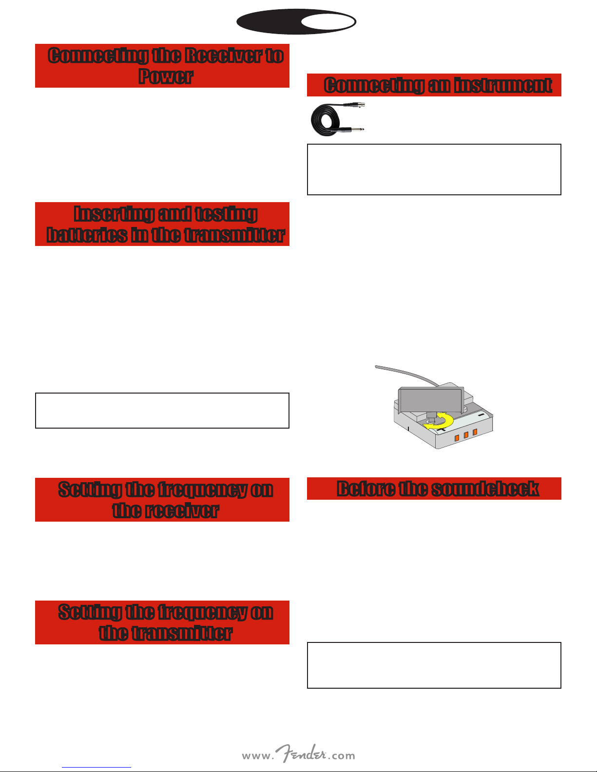
Connecting an instrument
Only use the supplied ITC3 instrument cable with the
Bodypack Transmitter.
Fender cannot guarantee that the pocket transmitter
i
1) Remove the battery compartment cover.
2) Plug mini XLR connector on the ITC3 instrument cable into the
input socket of the pocket transmitter, then plug the other end of
the ITC3 cable into your instrument.
3) Turn the pocket transmitter on by setting the on/o switch to
“O N”.
4) Set the SQUELCH control on the receiver to minimum and switch
the receiver on.
5) Play your instrument.
6) Use the screwdriver integrated in the battery compartment cover
to set the GAIN control to a position where the CLIP LED on the
receiver will ash occasionally when you are playing your instrument at maximum volume.
will work perfectly with products from other manufacturers and any damage that may result from such use is
not covered by the Fender warranty.
ENGLISH
If you use a rechargeable battery, the LED will change to
i
5) To close the battery compartment, slide the battery compartment
cover onto the battery compartment from below until the snap
hook engages.
red approximately 15 minutes before the battery goes
at.
Setting the frequency on
the receiver
Set the transmitter and receiver to the same frequency:
1) Set the desired channel number by pressing CHANNEL. With each
press of the button, the channel number increases by one.
2) The set channel is indicated on the display and activated
immediately.
Setting the frequency on
the transmitter
1) Switch the receiver on and press CHANNEL. The selected channel (e.g. 1) blinks for 3 seconds after which it is displayed without
blinking, indicating that the selected channel is active.
2) During those 3 seconds, press CHANNEL to obtain the required
channel number. Each press of the button increases the channel
number by one.
3) Once you have reached the required channel number, the display
7) Replace the battery compartment cover on the transmitter.
Before the soundcheck
1) Move the transmitter around the area where you will use the system to check the area for “dead spots”, i.e. places where the eld
strength seems to drop and reception deteriorates. If you nd any
dead spots, try to eliminate them by repositioning the receiver. If
this does not help, avoid the dead spots.
2) If the RF OK LED on the receiver goes out, this means no signal is
being received or the squelch is active. Switch the transmitter on,
move closer to the receiver or adjust the squelch level to the point
where the green RF OK LED lights up.
3) If interference noise occurs, adjust the squelch level until the interference noise goes away.
Do not set the squelch level higher than necessary. The
i
higher the squelch level, the lower the sensitivity of the
receiver and hence the smaller the range between transmitter and receiver.
4
Page 6
FWG
1010
Troubleshooting
PROBLEM POSSIBLE CAUSE REMEDY
No sound 1. AC ada pter is not connec ted to receiver and/or po wer outlet.
ENGLISH
Noise, crackling, unwanted signals. 1. Antenna location.
Distortion. 1. GAI N control on transm itter is set too hig h or too low.
2. Re ceiver is OFF.
3. Re ceiver is not connec ted to mixer or ampli er.
4. VOLUM E control on receive r is at zero.
5. Ins trument is not con nected to pocke t transmitter.
6. Transm itter has a dier ent frequency r ange or is tuned to a di erent frequen cy
from the receiver.
7. Transm itter on/o switch i s at “OFF” or “MUTE”.
8. Transmitter batteries are not inserted properly.
9. Transm itter batter ies are dead.
10. Transmitt er is too far away from r eceiver or squelch l evel set too high.
11. Obstr uctions bet ween transmitt er and receiver.
12. No line of sig ht between tran smitter and recei ver.
13. Receiver i s too close to metal o bjects.
2. Interference from other wireless systems, TV, radio, CB radios, or defective electrical appliances or installations.
2. Interference from other wireless systems, TV, radio, CB radios, or defective electrical appliances or installations.
3. Antenna location.
1. Con nect AC adapter to re ceiver and/or power out let.
2. Pu sh ON/OFF switch to sw itch receiver ON.
3. Con nect receiver o utput to mixer or ampl ier input.
4. Turn up VO LUME control.
5. Con nect instru ment to audio input on t he pocket transmi tter.
6. Use a t ransmitter wi th the same frequ ency range as the r eceiver or tune
both to the s ame frequenc y.
7. Se t transmitter o n/o switch to “ON”.
8. Ins ert batteri es conforming to “+” and “-” marks.
9. Replace transmitter batteries.
10. Move close r to receiver or reduc e squelch level.
11. Remove obstruc tions.
12. Avoid spots where you cannot see receiver.
13. Remove interfering objects or move receiver away from them.
1. Re locate receiver or a ntennas.
2. Swi tch o interfere nce sources or defe ctive applianc es or tune transmit ter
and receiv er to a dierent fre quency; have elec trical inst allation checked .
1. De crease or increa se GAIN setting j ust enough to stop t he distortion .
2. Swi tch o interfere nce sources or defe ctive applianc es or tune transmit ter
and receiv er to a dierent fre quency; have elec trical inst allation checked .
3. Re locate receiver or a ntennas. If dead spot s persist, mar k and avoid them.
Specifications
RECEIVER TRANSMITTER
Carrier frequencies 530.025-559.000 MHz (Ban d A)
826.300-831.000 MHz (Band M)
863.100-864.900 MHz (Band D)
Switching b and width up to 30 MHz (Depen ds on the used freq uency band) 30 MHz (Depen ds on the used freq uency band)
Modulation FM FM
Audio transmission bandwidth 40 - 20,000 H z 40 - 20,000 H z
Total harmonic distortion at 1 kHz t yp. 0.8% typ. 0.8%
Signal/S/N ratio typ. 105 dB(A) typ. 105 dB(A)
Transmission power – 10 mW, 50 mW (Depends on the us ed frequency b and)
Voltage supply Power supply u nit 12 V / 500 mA (or via antenna spli tter) 1x 1.5 V battery size AA
Operating time – 6 - 8 h (Depends on RF power used)
Squelch threshold -100 to -70 dBm, adjustable –
Audio output XLR symme tric and 1/4” (6.3 mm) jack plug asym metric: Adjust-
able fro m microphone to line l evel. Output level a t rated travel: 500 mV e.
Dimensions: 200 x 150 x 45 mm (withou t antennas) 60 x 74 x 30 mm
Weight : 37 3 g 60 g
530.025-559.000 MHz (Ban d A)
826.300-831.000 MHz (Band M)
863.100-864.900 MHz (Band D)
–
Only for frequency bands designed for use in the EC: This product corresponds to the standards stated in the Declaration of Conformity.
5
Page 7
FWG
1010
Símbolos utilizados
El símbolo de rayo dentro de un triángulo signica que
existen tensiones peligrosas en el equipo.
El signo de exclamación dentro de un triángulo en el equi-
po indica que el usuario debe consultar el manual de usuario. En el manual de usuario, este símbolo identica las
instrucciones que debe seguir el usuario para garantizar
el funcionamiento seguro del equipo.
Seguridad y medio ambiente
Seguridad
• No derrame ningún líquido sobre el aparato.
• No coloque ningún recipiente con uidos sobre el aparato o la
fuente de alimentación.
• El aparato debe utilizarse sólo en lugares secos.
• Sólo el personal especializado autorizado puede abrir, mantener
y reparar el aparato. En el interior de la caja no se encuentra ninguna pieza que pueda ser mantenida, reparada o recambiada
por inexpertos.
• Antes de poner en funcionamiento el equipo, verique que la
tensión de red indicada en el adaptador de red se corresponda
con la tensión de red en el lugar de uso.
• Utilice el equipo sólo con el adaptador de red suministrado con
una tensión de salida de 12 V CC. ¡Todos los demás tipos de corriente y tensiones pueden dañar seriamente el aparato!
• Interrumpa inmediatamente el funcionamiento del equipo si llegara a penetrar en el aparato algún objeto sólido o un líquido. En
este caso, saque inmediatamente del enchufe de red del adaptador de red y haga examinar el equipo por nuestro servicio de
atención al cliente.
• Saque el adaptador de red en caso de no utilizarlo por mucho tiempo. Tenga en cuenta que, al desconectar el equipo, éste no se
desconecta completamente de la red si el adaptador de red está
conectado.
• No coloque el aparato cerca de fuentes de calor, como radiadores, tubos de calefacción, amplicadores, etc., y no lo exponga
directamente a la luz solar, a polvo o humedad intensos, a lluvia,
vibraciones o golpes.
• Para evitar perturbaciones o interferencias, haga el tendido de
todos los cables, y sobre todo los de las entradas de micrófono, separado de las líneas de alta tensión y de las líneas de alimentación. Si hace el tendido en cajas o canales de cables, preste
atención a colocar las líneas de transmisión en un canal separado.
• Limpie el aparato con un paño húmedo, pero no mojado. Antes
de proceder a la limpieza, desenchufe el adaptador de red. En
ningún caso debe utilizar productos de limpieza corrosivos o
abrasivos o aquellos que contengan alcohol o disolventes, ya que
pueden dañar el barniz y las piezas de plástico.
• Utilice el aparato únicamente para los nes descritos en estas instrucciones de uso. Fender no se responsabiliza en caso de daños
causados por un uso inadecuado o indebido.
Medio ambiente
• El alimentador de red consume también una cantidad reducida
de electricidad si el aparato está desconectado. Para ahorrar energía, saque el alimentador del enchufe de red si no va a utilizar
el aparato durante un tiempo prolongado.
• El embalaje es reciclable. Elimine el embalaje a través de un sistema de recogida previsto al efecto.
• Al proceder al desguace del aparato, separe la caja, la electrónica y los cables y elimine todos los componentes según las correspondientes disposiciones de eliminación de residuos.
1. GENERALIDADES
Introducción
Gracias por adquirir un p roducto Fender. Este manual contiene instrucciones importantes para la instalación y el manejo de su equipo. Le
rogamos dedique unos minutos a leer con detenimiento las siguientes
instrucciones antes de manejar el equipo. Conserve el manual para
futuras consultas. ¡Deseamos que disfrute utilizando su sistema!
Accesorios/piezas
Número de pieza Pieza
7704710000 PASSIVE DIRECTIONAL ANTENNA
7744711000 ACTIVE DIRECTIONAL ANTENNA
7704712000 PASSIVE WD-BND OMNIDIRECTIONAL ANTENNA
7704713000 ACTIVE WD-BND OMNIDIRECTIONAL ANTENNA
7704714000 POWER SW SUPPLY 12V 500 MA MULTIPLUG
7704715000 BODY PACK TRANSMITTER CHARGING STATION
7704721000 PT1010 WIRELESS BODY PACK TRANSMITTER
7704717000 FMKPS ANTENNA CABLE 2 FT 65 CM
7704718000 FMKA5 ANTENNA CABLE 16 FT 5 M
7704719000 FMKA20 ANTENNA CABLE 66 FT 20 M
7704720000 FRONT MOUNT ANTENNA RACKMOUNT KIT
7704722000 ITC3 INSTRUMENT TRANSMITTER CABLE 3 FT
ESPAÑOL
6
Page 8
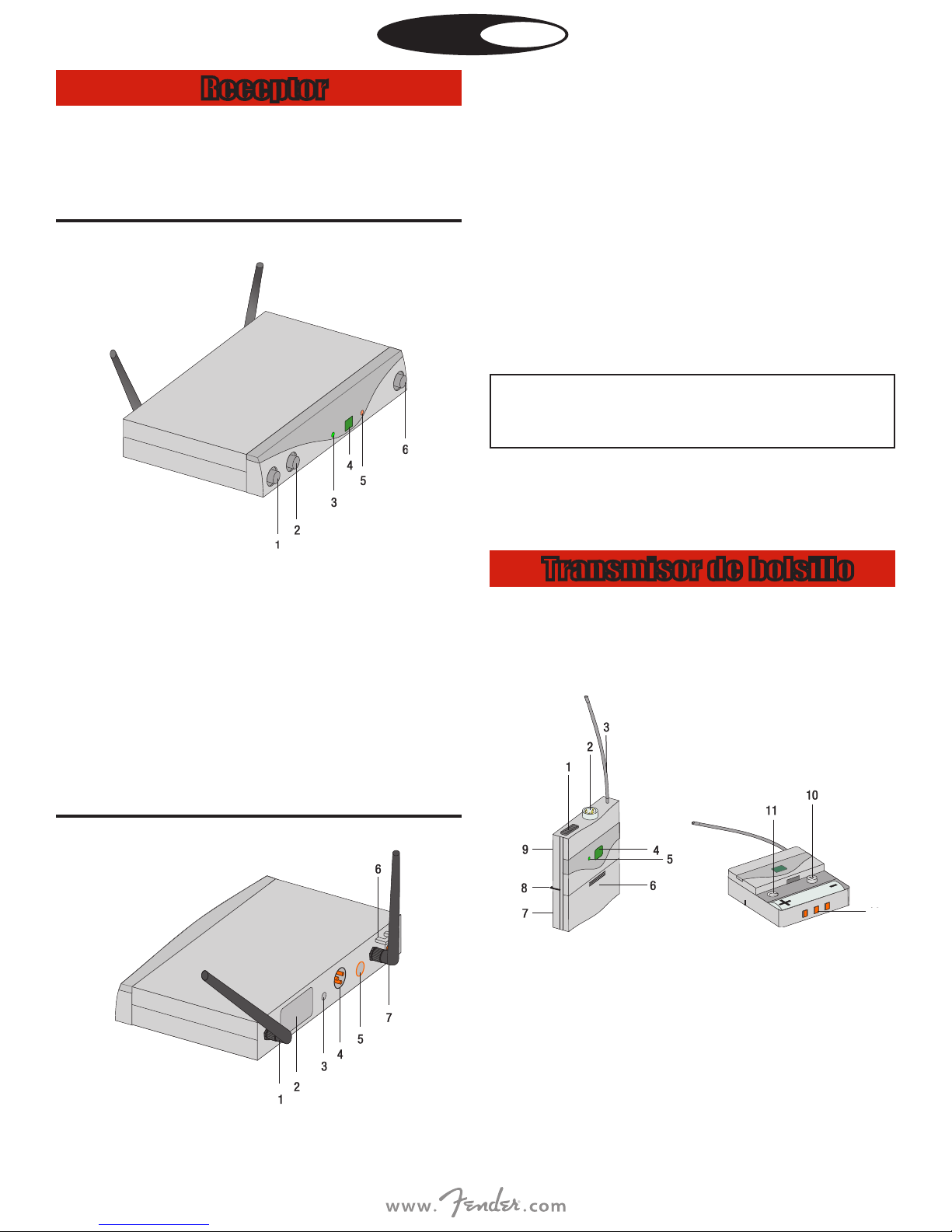
Receptor
El SR1010 es un receptor estacionario para todos los emisores del
sistema FWG1010. El SR1010 trabaja en un ancho de banda de hasta 30
MHz en el rango de frecuencia portadora UHF de 530,025 MHz hasta
931,850 MHz y se puede conmutar entre hasta 8 frecuencias portadoras diferentes.
Panel frontal
ESPAÑOL
FWG
1010
reverso del receptor hay una etiqueta adhesiva que indica el rango
de frecuencia portadora. Podrá encontrar información sobre las
frecuencias ajustables en la descripción general de frecuencias
que se adjunta.
3 SQUELCH: El silenciamiento de ruido (“Squelch”) apaga el recep-
tor si la señal de recepción es demasiado débil, así los ruidos de
interferencia correspondientes o los ruidos propios del receptor
no se oirán cuando el emisor está apagado. Ajuste el regulador
SQUELCH al mínimo antes de encender el receptor por primera
vez.
4 AUDIO OUT/BALANCED: Salida de audio simétrica en toma XLR
de 3 polos: Puede conectar esta salida, por ejemplo, con una
entrada de una mesa de mezclas.
5 AUDIO OUT/UNBALANCED: Salida de audio asimétrica en conec-
tor Jack mono de 6,3 mm. Aquí puede conectar, por ejemplo, un
amplicador de guitarra.
Si se utilizan ambas tomas de salida simultáneamente
i
6 Descarga de tensión para el cable de alimentación del enchufe
para red suministrado.
7 DC IN: Toma de alimentación para la conexión del enchufe para
red suministrado.
(BALANCED y UNBALANCED) pueden producirse, bajo
ciertas circunstancias, pérdidas de nivel o incremento de
ruidos.
1 ON/OFF: Tecla con/des.
2 VOLUME: Con este control giratorio puede atenuar el nivel de la
salida de audio en continuo.
3 RF OK : Este LED se ilumina cuando se recibe una señal. Cuando
no se recibe ninguna señal o está activo el silenciador de ruido de
fondo automático (Squelch), se apaga el LED RF OK y se silencia la
salida de audio.
4 Display: Muestra el canal de recepción ajustado.
5 CLIP: Este LED se ilumina cuando el nivel de audio es excesivo.
6 CHANNEL: Con esta tecla puede ajustar el receptor a una de las 8
frecuencias portadoras diferentes dentro de la banda de frecuencias portadoras del receptor.
Reverso
1 ANTENNA A/B: Toma BNC para la conexión de las dos antenas
UHF suministradas u otras posibles antenas independientes.
2 Carrier frequency label: Etiqueta de frecuencia portadora: En el
Transmisor de bolsillo
El transmisor de bolsillo PT1010 puede conectarse una guitarra eléctrica, un bajo eléctrico o un teclado en bandolera. El PT1010 funciona
con un ancho de banda de hasta 30 MHz en una gama de frecuencia
portadora UHF de entre 530,025 MHz y 931,850 MHz y se puede adaptar a hasta 8 frecuencias portadoras diferentes.
12
1 ON/OFF Interruptor: Este interruptor deslizable tiene tres
posiciones:
ON: La fuente de alimentación para el emisor está encendida.
MUTE: La señal de audio procedente del instrumento está en
modo mudo, la fuente de alimentación y la frecuencia portadora
HF se mantienen no obstante encendidas.
OFF: La fuente de alimentación para el emisor está apagada.
2 Tomas de entrada de audio: Toma mini XLR de 3 polos con con-
tactos para nivel de línea. A través de la conexión de enchufe
de los cables de ITC3, los contactos adecuados se asignan
automáticamente.
7
Page 9
FWG
1010
3 Antena: Antena exible de montaje jo.
4 Display: Muestra el canal de emisión congurado.
5 LED de control: Este LED muestra la disponibilidad de servicio del
emisor.
El LED se ilumina en verde: Las pilas funcionan correctamente.
El LED se ilumina en rojo: Desde el momento en que se ilumina
en rojo, la capacidad de la pila será suciente para un máximo de
1 hora de funcionamiento. Recomendamos cambiar las pilas por
otras nuevas lo antes posible.
6 Compartimento de pilas con destornillador integrado.
7 Ventana: A través de la ventana puede comprobar en todo
momento si hay una pila o una pila recargable en el compartimento de pilas.
8 Clip para el cinturón: Para jar el emisor portátil al cinturón.
9 Etiqueta de frecuencia portadora: En el reverso del emisor hay
una etiqueta adhesiva que indica el rango de frecuencia portadora. Podrá encontrar información sobre las frecuencias ajustables
en la descripción general de frecuencias que se adjunta.
10 CHANNEL: Con esta tecla puede ajustar el emisor a una de las 8
frecuencias portadoras diferentes dentro del rango de frecuencia
portadora del emisor.
11 GAIN: Con este regulador puede ajustar la sensibilidad de la entra-
da de audio al nivel del instrumento conectado.
12 Contactos de carga: Los contactos de carga encastrados le per-
miten cargar una pila recargable con ayuda del cargador opcional
sin tener que sacar la pila recargable del compartimento de pilas.
2. PUESTA EN
FUNCIONAMIENTO
Antenas remotas
Debe utilizar antenas de montaje remoto en el caso de que la posición
del receptor no permita una buena recepción.
• Conecte las antenas remotas en los conectores BNC situados en la
parte posterior del receptor.
• Utilice el cable de extensión BNC (Front Mount Antenna Rack
Mount Kit P/N 7704720000) para montar las antenas de ¼ de onda
en el panel frontal.
• Utilice cables RG58 ó RG213 para conectar las antenas.
Conecte el receptor a una
entrada simétrica
1) Conecte con un cable XLR la toma BALANCED en la parte posterior del receptor con la entrada simétrica deseada (toma XLR) en el
pupitre de mezcla o amplicador.
2) Gire el regulador VOLUME en el receptor del todo hacia la izquierda (nivel del micrófono).
Conecte el receptor a la red
1)
ATENCIÓN: Verique que la tensión de alimentación indicada
en el alimentador de red suministrado sea la misma que la disponible en el lugar en el que se usará el receptor. Si usa el alimentador de red con una tensión de alimentación diferente,
puede causar daños al equipo.
2) Enchufe el cable de alimentación del adaptador de red suministrado en la toma IN CC del receptor.
3) Introduzca el adaptador de red en un enchufe de red.
4) Conecte el receptor pulsando la tecla ON/OFF.
ESPAÑOL
Colocación del receptor
• Coloque el receptor de forma independiente.
• Los reejos de la señal emitida en piezas metálicas, paredes, techos,
etc. o las sombras de cuerpos humanos, pueden debilitar o eliminar
la señal directa del transmisor.
Por lo tanto, coloque el receptor de la siguiente forma:
1) Coloque el receptor siempre cerca del área de acción (escenario),
pero dejando una distancia mínima entre el transmisor y el receptor
de 3 m hasta la óptima de 5 m.
2) El requisito para la recepción óptima es el contacto visual entre el
transmisor y el receptor.
3) Coloque el receptor a una distancia de más de 1,5 m de objetos
metálicos de gran tamaño, paredes, andamios del escenario y
techos, entre otros.
Conexión de las antenas
Las antenas de ¼ de onda suministradas pueden montarse rápida y
fácilmente y son aptas para aplicaciones en las que se dispone de un
ángulo visual directo entre el transmisor y la antena del receptor y
donde desee emplearse un sistema inalámbricos sin necesidad de un
arduo trabajo de instalación.
Colocar y comprobar pilas
en el transmisor
1) Presione hacia abajo los ganchos de la tapa del compartimento de pilas.
2) Extraiga la tapa del compartimento de pilas del transmisor en el
sentido de la echa.
3) Coloque la pila suministrada en el compartimento y compruebe la
polaridad correcta de la pila. Si coloca la pila de forma incorrecta,
el transmisor no recibirá corriente.
4) Conecte el transmisor colocando el conector con/des en la
posición “ON”. Si la pila está en buen estado, el LED de control se
iluminará en verde. Si el LED de control comienza a iluminarse en
rojo, la pila se agotará en aprox. 1 hora. Cambie la pila lo antes
posible por una nueva. Si el LED de control no se ilumina, la pila
estará agotada. Coloque una pila nueva.
Si se utiliza un acumulador, el LED cambia a rojo aprox 15
i
5) Cierre el compartimento deslizando desde abajo la tapa del compartimento hasta que encaje el gancho.
minutos antes de la descarga completa.
8
Page 10
FWG
1010
Ajuste de frecuencia en
receptor
Ajuste la misma frecuencia para el transmisor y el receptor:
1) Pulsando en CHANNEL ponga el número de canal deseado. Con
cada pulsación, el número subirá a un canal superior.
2) El cana l seleccionado aparece en el display y se acti va de inmediato.
Ajuste de frecuencia en
transmisor
1) Conecte el dispositivo o ajuste el dispositivo ya encendido en
ESPAÑOL
CHANNEL. El canal ajustado (por ejemplo, 1) comenzará a parpadear en el display durante 3 segundos, posteriormente el indicador volverá a estabilizarse y se activará el canal ajustado.
2) Almacene el canal en el número deseado pulsando CHANNEL
durante 3 segundos. Cada vez que lo pulse, el canal saltará a un
número superior.
3) Cuando haya llegado al canal deseado, parpadeará el diplay
durante aprox. 3 segundos y se activará el nuevo canal ajustado.
Conexión de instrumentos
Antes de la comprobación
del sonido
1) Mida el área en la que desea emplear el transmisor. Compruebe los
puntos en los que disminuye la potencia de campo y en los que,
por tanto, se producirán interrupciones breves de la recepción
(“dropouts”). Podrá evitar dichos dropouts colocando el receptor
en otra posición. Si no lo consigue, evite estos puntos críticos.
2) Cuando se apague el LED RF OK en el receptor, esto indicará que
no se recibe ninguna señal o que la función Squelch está activa.
Conecte el transmisor, acérquese al receptor y ajuste el regulador
Squelch de forma que se ilumine el LED verde RF OK.
3) En caso de que se produzcan ruidos molestos, ajuste el regulador
Squelch hasta que dejen de oírse.
Nunca ajuste el regulador Squelch más alto de lo real-
i
mente necesario. Cuanto más alto se ajuste el regulador
Squelch, menor será la sensibilidad del receptor y, por
tanto, el alcance entre el transmisor y el receptor.
Utilice sólo el cable de instrumento ITC3 que se
incluye con transmisor bolsillo.
Rogamos tener presente que Fender no puede garan-
i
1) Retire la tapa del compartimento de pilas.
2) Coloque los jacks del cable de la guitarra ITC3 en las tomas de salida de su instrumento y el conector Mini-XLR del cable de la guitarra en la toma de salida de audio del transmisor de bolsillo.
3) Conecte el transmisor de bolsillo colocando el conector con/des
en la posición”ON”.
4) Ajuste al mínimo el regulador SQUELCH en el receptor y conecte el
receptor.
5) Toque el instrumento.
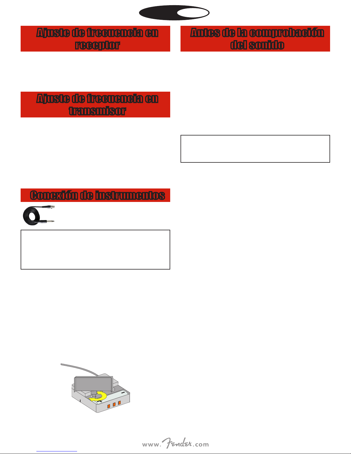
6) Coloque el regulador GAIN con el destornillador integrado en la
tapa del compartimento de pilas de forma que el LED CLIP del
receptor se ilumine brevemente.
tizar un funcionamiento impecable del transmisor de
bolsillo con productos de otros fabricantes y que, por lo
tanto, los posibles daños causados por el funcionamiento con esos productos de otros fabricantes quedarán
excluidos de la prestación de garantía.
7) Vuelva a colocar la tapa del compartimento de pilas en el
transmisor.
9
Page 11

FWG
1010
Corrección de errores
ERROR POSIBLE CAUSA CORRECCIÓN
Sin sonido 1. El adaptad or de red no está cone ctado en el rece ptor o al enchufe de re d.
Ruidos, chasquidos o señales no deseadas
2. El r eceptor está des conectado.
3. El r eceptor no está con ectado ni a un pup itre de mezcla ni a un am plicador.
4. El r egulador VOLUME del re ceptor está en cero.
5. Ni e l instrumento es tán conectad os al transmisor de b olsillo.
6. El t ransmisor tiene un a banda de frecue ncia diferente al re ceptor o la frecue ncia
ajustad a es diferente.
7. El co nmutador con/des de l transmisor est á en “OFF” o “MUTE”.
8. L as pilas están mal co locadas en el trans misor.
9. Las pilas del transmisor están agotadas.
10. El transmi sor está demasia do lejos del recepto r o el nivel SQUELCH est á ajustado demasiado alto.
11. Hay obstá culos entre el tra nsmisor y el recepto r.
12. No hay contac to visual entre el t ransmisor y el rece ptor.
13. El recepto r está demasiado ce rca de objetos met álicos.
1. Pos ición de la antena.
2. Molestias por otros dispositivos inalámbricos, televisores, radio, equipos radioeléctricos o instalaciones o aparatos eléctricos defec tuosos.
1. Con ectar el adapt ador de red al recepto r y la red.
2. Con ectar el recep tor con la tecla ON/OFF.
3. Con ectar la salida d el receptor con la ent rada del pupitre de m ezcla o del
amplicador.
4. Ab rir el regulador VOLUM E
5. Con ectar el inst rumento con la entra da de audio del transm isor de bolsillo.
6. Ut ilizar en el transm isor la misma banda de f recuencia que en e l receptor o
ajustar la misma frecuencia.
7. Col ocar el conmutad or cond/des del trans misor en “ON”.
8. Volver a colocar las pilas en el compartimento siguiendo las indicaciones de
polaridad.
9. Col ocar pilas nuevas e n el transmisor.
10. Acercar se al receptor o redu cir el nivel de SQUELCH.
11. Retirar los obst áculos.
12. Evitar lo s puntos desde los qu e no se pueda ver el rece ptor.
13. Retirar l os objetos moles tos o instalar el rec eptor algo más lejos.
1. Ins talar el receptor e n otro lugar.
2. De sconectar lo s aparatos moles tos o defectuo sos o utilizar el F WG1010 con
otra frecuencia portador a; hacer revisar la instalación eléctrica.
ESPAÑOL
Distorsiones 1. El r egulador GAIN se ha aju stado demasiado a lto o bajo.
2. Molestias por otros dispositivos inalámbricos, televisores, radio, equipos radioeléctricos o instalaciones o aparatos eléctricos defec tuosos.
3. Pos ición de la antena.
Características técnicas
RECEPTOR TRANSMISOR
Frecuencia portadora 530.025-559.000 MHz (Ban da A)
Ancho de ban da de hasta 30 MHz (Depen diendo de la banda de f recuencia utili zada) 30 MHz (Depen diendo de la banda de f recuencia utili zada)
Modulación FM FM
Ancho de ban da de transmisión de
audio
Factor de dis torsión a 1 kHz t íp. 0,8% típ. 0,8%
Relación señal/ruido típ. 105 dB(A) típ. 105 dB(A)
Potencia de emisión – 10 mW, 20 mW (Dependien do de la banda de frec uencia utiliza da)
Fuente de alimentación Bloque de al imentación 12 V / 500 mA (o a travé s del divisor de
Tiempo de servicio – 6 - 8 h (Dependiendo de la potencia de RF utilizada)
Umbral del Squelch -100 hasta -70 dBm regulab le –
Salida de au dio XLR sim. y cone ctor Jack 6,3 mm asim .: Regulable desde n ivel mi-
Medidas 200 x 150 x 45 mm (Sin antenas) 60 x 74 x 30 mm
Peso neto 373 g 60 g
826.300-831.000 MHz (Banda M)
863.100-864.900 MHz (Banda D)
40 - 20,000 H z 40 - 20,000 H z
antena)
crófon o hasta nivel de línea . Nivel de salida con de sviación nominal: 500 mV rms
1. Girar el regulador GAIN hasta que se eliminen las distorsiones.
2. De sconectar lo s aparatos moles tos o defectuo sos o utilizar el F WG1010 con
otra frecuencia portador a; hacer revisar la instalación eléctrica.
3. Ins talar el receptor e n otro lugar. En caso de qu e permanezcan los d ropouts, marcar y evitar los puntos críticos.
530.025-559.000 MHz (Ban da A)
826.300-831.000 MHz (Banda M)
863.100-864.900 MHz (Banda D)
1x 1,5 V pila tamaño AA
–
Sólo para bandas de frecuencia diseñadas para uso en la CE: Este producto cumple con las normas indicadas en la declaración de conformidad.
10
Page 12

FWG
1010
Symboles utilisés
Le symbole représentant un éclair avec une èche à l’in-
térieur d’un triangle équilatéral est utilisé pour prévenir
l’utilisateur de la présence de tensions électriques dangereuses à l’intérieur de l’appareil.
Le symbole représentant un point d’exclamation à l’intérieur d’un triangle équilatéral, tel qu’il gure sur l’appareil,
indique qu’il est nécessaire pour l’utilisateur de consulter le
mode d’emploi. Celui-ci utilise ce symbole pour signaler des
instructions que l’utilisateur doit suivre an d’assurer un
fonctionnement de l’appareil en toute sécurité.
Sécurité et environnement
Environnement
• L’adaptateur secteur consomme toujours un peu de courant même
lorsque l’appareil est hors tension. Pour économiser le courant, pensez donc à débrancher l’adaptateur secteur lorsque l’appareil restera
un certain temps sans être utilisé.
• L’emballage est recyclable. Déposez celui-ci dans un récipient de collecte prévu à cet eet.
• Si vous mettez l’appareil aux vieilles matières, séparez le boîtier, le
système électronique et les câbles, puis procédez à l’élimination des
composants conformément à la législation en vigueur.
1. DESCRIPTION
Introduction
Sécurité
• Ne pas renverser de liquide sur l’appareil.
• Ne placez pas de récipient rempli de liquide sur l’appareil ou le bloc
FRANÇAIS
secteur.
• L’appareil ne doit être utilisé que dans des locaux secs.
• Cet appareil ne peut être ouvert, entretenu et réparé que par le
personnel technique autorisé. On ne trouve à l’intérieur du boîtier
aucun élément pouvant être entretenu, réparé ou remplacé par un
profane.
• Avant de mettre l’appareil en service, vériez si la tension de service
indiquée sur le bloc d’alimentation livré correspond à la tension
secteur sur le lieu d’utilisation.
• N’utilisez l’appareil qu’avec le bloc d’alimentation livré et avec une
tension de sortie de 12 V DC. Toute autre nature de courant ou de
tension risque de provoquer de sérieux dégâts sur l’appareil !
• Interrompez immédiatement le fonctionnement de l’appareil si un
objet quelconque ou du liquide devait pénétrer à l’intérieur de l’appareil. Dans une telle situation, débranchez le bloc d’alimentation
de la prise et faites procéder à une inspection de l’appareil par notre
service après-vente.
• Débranchez l’adaptateur secteur de la prise en cas d’inutilisation
prolongée de l’appareil. Notez que, lorsque le bloc d’alimentation
est branché sur la prise secteur, l’appareil n’est pas entièrement
coupé du secteur lorsque vous le mettez hors tension.
• Ne placez pas l’appareil à proximité d’une source de chaleur (p. ex.
radiateurs, tuyaux de chauage, amplicateurs, etc.), ni à un endroit
où il risque d’être exposé au rayonnement solaire direct, à une
atmosphère poussiéreuse, à l’humidité, à la pluie, aux vibrations ou
aux secousses.
• Pour éviter les parasites et les interférences, installez tous les câbles,
en particulier ceux des entrées micro, séparément des câbles de
puissance et des câbles d’alimentation secteur. En cas de pose dans
des canaux ou conduites pour câbles, les câbles de transmission
devront toujours être posés dans une conduite séparée.
• Pour nettoyer l’appareil, utilisez un chion légèrement humide,
jamais un chion mouillé. Débranchez impérativement le bloc
d’alimentation auparavant de la prise secteur. N’utilisez jamais de
produits de nettoyage corrosifs ou abrasifs, ni de produits contenant de l’alcool ou un solvant susceptible d’endommager la laque et
les éléments en plastique.
• N’utilisez l’appareil que dans le cadre des applications décrites dans
la présente notice d’utilisation. Fender décline toute responsabilité
concernant les dégâts résultant d’une manipulation inappropriée
ou d’une utilisation non conforme.
Merci d’avoir choisi ce produit Fender. Ce manuel contient des instructions importantes pour monter et utiliser votre nouvel équipement.
Lisez attentivement les instructions ci-dessous avant d’utiliser le
matériel. Conservez le manuel pour vous y reporter ultérieurement.
Nous espérons que ce système vous donnera entière satisfaction !
Accessoieres/Parts
Numéro Référence
7704710000 PASSIVE DIRECTIONAL ANTENNA
7744711000 ACTIVE DIRECTIONAL ANTENNA
7704712000 PASSIVE WD-BND OMNIDIRECTIONAL ANTENNA
7704713000 ACTIVE WD-BND OMNIDIRECTIONAL ANTENNA
7704714000 POWER SW SUPPLY 12V 500 MA MULTIPLUG
7704715000 BODY PACK TRANSMITTER CHARGING STATION
7704721000 PT1010 WIRELESS BODY PACK TRANSMITTER
7704717000 FMKPS ANTENNA CABLE 2 FT 65 CM
7704718000 FMKA5 ANTENNA CABLE 16 FT 5 M
7704719000 FMKA20 ANTENNA CABLE 66 FT 20 M
7704720000 FRONT MOUNT ANTENNA RACKMOUNT KIT
7704722000 ITC3 INSTRUMENT TRANSMITTER CABLE 3 FT
11
Page 13

FWG
Récepteur
Le SR1010 est un récepteur stationnaire pour tous les émetteurs du
système FWG1010. Le SR1010 travaille dans une largeur de bande
allant jusqu’à 30 MHz dans une gamme de fréquences porteuses UHF
de 530,025 MHz à 931,850 MHz et peut être commuté sur un maximum
de 8 fréquences porteuses diérentes.
Panneau avant
1010
dos du récepteur. Vous trouverez des informations relatives aux
fréquences réglables dans la vue d’ensemble des fréquences
jointe.
3 SQUELCH : Le circuit d’assourdissement (“Squelch”) éteint le
récepteur en cas de signal de réception trop faible, de manière à ce
que les bruits parasites ou le propre bruit du récepteur ne soient
pas audibles une fois l’émet teur éteint. Réglez le contrôle SQUELCH
sur minimum avant d’allumer le récepteur pour la première fois.
4 AUDIO OUT/BALANCED : Sortie audio symétrique sur une prise
XLR à 3 pôles : Vous pouvez par exemple raccorder cette sortie à
une entrée d’une table de mixage par exemple.
5 AUDIO OUT/UNBALANCED : Sortie audio asymétrique sur un jack
mono de 6,3 mm. Vous pouvez par exemple brancher ici un amplicateur de guitare.
Si les deux jacks de sortie (BALANCED et UNBALANCED)
i
6 Soulagement de traction pour le câble d’alimentation du bloc
secteur livré.
7 DC IN : Prise d’alimentation pour le raccordement du bloc secteur
livré.
sont utilisés en même temps, des pertes de niveau peuvent apparaitre entrainant une amplication du bruit.
FRANÇAIS
1 ON/OFF : Touche Marche/Arrêt.
2 VOLUME : Ce régulateur rotatif vous permet de réduire le niveau
de la sortie audio en continu.
3 RF OK : Cette DEL est allumée lors de la réception d’un signal.
Si aucun signal n’est reçu ou bien si le Squelch automatique est
activé, la DEL RF OK s’éteint et la sortie audio est désactivée.
4 Display : Ache le canal récepteur réglé.
5 CLIP : Cette DEL est allumée lorsque le niveau audio est trop élevé.
6 CHANNEL : Cette touche permet de régler le récepteur sur l’une de
8 fréquences porteuses diérentes dans la gamme de fréquences
porteuses du récepteur.
Verso
1 ANTENNA A/B : Prises BNC pour raccorder les deux antennes UHF
livrées ou les antennes en option.
2 Étiquette de fréquence porteuse : Une étiquette portant la
désignation de la bande de fréquence porteuse est apposée au
Émetteur de poche
Vous pouvez raccorder à l’émetteur de poche PT1010 avec une guitare électrique, une basse électrique ou un clavier portable. Le PT1010
fonctionne dans une largeur de bande commutable jusqu’à 30 MHz
dans la gamme de fréquences porteuses UHF de 530,025 MHz à
931,850 MHz. Il peut être commuté au maximum sur 8 fréquences
porteuses diérentes.
12
1 Commutateur Marche/Arrêt : Ce curseur a trois positions :
ON : L’alimentation en tension pour l’émetteur est allumée.
MUTE : Le signal audio venant de l’instrument est muet, l’alimen-
tation en tension et la fréquence porteuse HF demeurent cependant allumés.
OFF : L’alimentation en tension pour l’émetteur est éteinte.
2 Fiche d’entrée audio : Fiche d’entrée mini XLR à 3 pôles à con-
tacts pour le niveau de ligne. L’aectation des ches du câble guitare ITC3 entraine une aectation automatiquement correcte des
contacts.
3 Antenne : Antenne montée en xe et exible.
4 Écran : Ache le canal d’émission réglé.
5 LED de contrôle : Cette LED ache la disponibilité de l’émetteur.
12
Page 14

FWG
1010
La LED s’allume vert : la pile est en ordre.
La LED s’allume rouge : dès le moment où la LED passe au rouge,
la capacité de la pile sut encore pour 1 heure de service maximum. Nous recommandons de remplacer la pile le plus tôt possible par une nouvelle.
6 Couvercle de compartiment à piles avec un tournevis intégré.
7 Regard : Grâce au regard, vous pouvez contrôler à tout moment si
une pile ou un accu se trouve dans le compartiment à piles.
8 Clip ceinture : Pour xer l’émetteur de poche à la ceinture.
9 Étiquette de fréquence porteuse : Une étiquette portant la
désignation de la bande de fréquence porteuse est apposée au
dos de l’émetteur. Vous trouverez des informations relatives aux
fréquences réglables dans la vue d’ensemble des fréquences
jointe.
10 CHANNEL : Cette touche vous permet de régler l’émetteur sur une
des 8 diérentes fréquences porteuses dans la plage de fréquence
porteuse de l’émetteur.
11 GAIN : Ce contrôle vous permet d’adapter la sensibilité de l’entrée
audio au niveau de l’instrument branché.
12 Pôles de charge : Les contacts de charge encastrés vous permet-
FRANÇAIS
tent de charger un accu à l’aide du chargeur optionnel sans devoir
retirer l’accu du compartiment à piles. Éteignez l’émetteur avant
de le charger.
2. MISE EN SERVICE
• Utilisez le câble d’extension BNC (Front Mount Antenna Rack
Mount Kit P/N 7704720000) pour xer les antennes quart d’onde
sur le panneau avant.
• Utilisez des câbles RG58 ou RG213 pour connecter les antennes.
Connexion du récepteur à
une entrée symétrique
1) À l’aide d’un câble XLR, reliez la prise BALANCED du panneau
arrière du récepteur à l’entrée symétrique souhaitée (prise XLR)
sur la table de mixage ou sur l’amplicateur.
2) Tournez à fond vers la gauche (niveau microphone) le bouton de
réglage de VOLUME du récepteur.
Raccordement du
récepteur au secteur
1) ATTENTION : Vériez que la tension indiquée sur l’adaptateur
fourni est identique à la tension du réseau du lieu d’utilisation de votre système. L’utilisation de l’adaptateur sous une
tension diérente peut gravement endommager l’appareil.
2) Branchez le câble d’alimentation du bloc d’alimentation fourni à la
prise DC IN du récepteur.
3) Branchez le bloc d’alimentation secteur sur une prise secteur.
4) Mettez le récepteur sous tension en appuyant sur la touche ON/
OFF.
Positionnement du récepteur
• Placez l’émetteur seul, sans rien autour.
• Les réexions du signal de l’émetteur sur les surfaces métalliques,
les murs, le plafond, etc. de même que l’écran du corps humain risquent d’aaiblir voire supprimer le signal direct de l’émetteur.
Respectez les points suivants: pour l’installation du récepteur :
1) Placez toujours le récepteur à proximité du lieu d’action (scène) en
respectant toutefois une distance minimale entre l’émetteur et le
récepteur de 3 à 5 m maximum.
2) Le contact visuel entre les points d’installation de l’émetteur et du
récepteur est une condition indispensable pour avoir une réception
optimale.
3) Placez le récepteur à plus de 1,5 m des objets métalliques volumineux, des murs, des décors, du plafond, etc.
Connexion des antennes
Les antennes quart d’onde fournies se montent facilement et rapidement et conviennent aux cas où une ligne de visée directe existe
entre l’émetteur et l’antenne du récepteur et où un système doit être
employé sans grands travaux d’installation.
Antennes distantes
Utilisez des antennes distantes si la position du récepteur ne permet
pas de bénécier des meilleures conditions de réception.
Installer et tester les piles
dans l’émetteur
1) Poussez vers le bas le fermoir à déclic du couvercle du compartiment de la pile.
2) Faites glisser le couvercle du compartiment de la pile dans le sens
de la èche pour le sortir de l’émetteur.
3) Introduisez la pile fournie dans le compartiment en respectant la
polarité. Si la pile est introduite à l’envers, l’émetteur ne sera pas
alimenté en courant.
4) Mettez l’émetteur sous tension en plaçant l’interrupteur marche/
arrêt sur la position « ON ». Si la pile est susamment chargée, la
DEL de contrôle s’allume en vert. Si la DEL de contrôle s’allume en
rouge, cela signie que la pile sera déchargée dans env. 1 heure.
Remplacer rapidement la pile usagée par une neuve. Si la DEL de
contrôle ne s’allume pas, la pile est déchargée. Installez une nouvelle pile.
Si vous utilisez un accu rechargeable, la DEL passe au
i
5) Fermez le compartiment de la pile en faisant glisser le couvercle,
introduit par le bas, jusqu’au déclic du fermoir.
rouge env. 15 minutes avant que l’accu ne soit complètement épuisé !
• Branchez les antennes distantes aux connecteurs BNC à l’arrière
du récepteur.
13
Page 15

FWG
1010
Réglage de la fréquence
récepteur
Réglez la fréquence de l’émetteur et du récepteur sur la même
fréquence:
1) En appuyant sur CHANNEL, placez le canal sur le chire souhaité.
Chaque pression sur le bouton fait passer le chire chaque fois à
un canal supérieur.
2) Le canal réglé s’ache à l’écran et est immédiatement actif.
Réglage de la fréquence
émetteur
1) Mettez l’appareil en fonctionnement ou bien appuyez sur
CHANNEL si l’appareil est déjà connecté. Le canal réglé (p. ex. 1)
commence à clignoter sur l’écran pour 3 secondes, ensuite l’achage demeure xe et le canal réglé est activé.
2) En appuyant pendant 3 secondes sur CHANNEL, amenez le canal
sur le chire souhaité. À chaque pression, le numéro de canal augmente d’une unité.
3) Lorsque vous avez atteint le canal souhaité, l’écran clignote encore
pendant 3 secondes et active le canal nouvellement paramétré.
Avant le soundcheck
1) Pénétrez avec l’émetteur dans le secteur où vous vous proposez
de l’utiliser. Repérez les endroits où l’intensité du champ semble
chuter et où la réception se détériore donc momentanément («
dropouts »). Vous pouvez éliminer les dropouts en modiant la
position du récepteur. Si cette opération n’apporte pas d’amélioration, évitez ces endroits critiques.
2) Si la DEL RF OK du récepteur s’éteint, cela signie qu’aucun signal n’est capté ou que le squelch automatique est activé. Mettez
l’émetteur sous tension, rapprochez-vous du récepteur ou réglez
le niveau squelch jusqu’à ce que la DEL RF OK s’allume.
3) En cas d’apparition de bruits parasites, réglez le niveau squelch
jusqu’à ce que ces bruits cessent.
Ne réglez jamais le niveau squelch plus haut que néces-
i
saire. Plus le niveau squelch est élevé, plus faible sera la
sensibilité du récepteur et ainsi la portée entre l’émetteur et le récepteur.
FRANÇAIS
Branchement d’un instrument
Utilisez uniquement le câble d’instrument ITC3 fourni avec l’émetteur de poche.
Nous attirons votre attention sur le fait qu’Fender ne
i
1) Retirez le couvercle du compartiment de la pile.
2) Connectez la che jack du câble de guitare ITC3 à la prise de sortie
de votre instrument, et la che mini XLR du câble de guitare à la
prise d’entrée audio de l’émetteur de poche.
3) Mettez l’émetteur de poche sous tension en positionnant l’interrupteur Marche/Arrêt sur « ON ».
4) Régler le bouton de réglage SQUELCH du récepteur sur le minimum et connectez l’émetteur.
5) Jouez de votre instrument.
6) À l’aide du tournevis intégré au couvercle du compartiment de la
pile, ajustez le bouton GAIN jusqu’à ce que la DEL CLIP du récepteur s’allume brièvement.
peut garantir un fonctionnement parfait de l’émetteur
de poche avec câbles d’autres marques et que d’éventuels dégâts provoqués par l’utilisation avec d’autres
marques ne sont pas couverts par la garantie.
7) Refermez le couvercle du compartiment de la pile de l’émetteur.
14
Page 16

FWG
1010
Élimination des erreurs
DYSFONCTIONNEMENT CAUSE POSSIBLE AIDE
Pas de son 1. Le b loc d’alimentation n ’est pas bran ché au récepteur ou à la p rise secteur.
Soue, grésillements, signaux indésirables
Distorsions 1. Le ré glage du bouton GAIN e st trop élevé ou tr op faible.
FRANÇAIS
2. Le ré cepteur est déco nnecté.
3. Le ré cepteur n’est pas branc hé à la console de mixa ge ou à l’amplicateur.
4. Le b outon de réglage VOLUME s ur le récepteur est p lacé sur zéro.
5. l ’instrument n’est pa s raccordé à l’émetteu r de poche.
6. L’émetteur a un e bande de fréquen ces diérente de ce lle du récepteur ou bie n la
fréquence est paramétrée diéremment.
7. L’interr upteur Marche/Arrê t de l’émetteur est pla cé sur « OFF » ou sur « MUTE ».
8. Piles mal mises en place dans l’émetteur.
9. Les piles de l’émetteur sont vides.
10. L’émetteu r est trop loin du ré cepteur ou le niveau SQU ELCH est trop élevé.
11. Obstac les entre l’émette ur et le récepteur.
12. Aucune liai son visuelle entr e l’émette ur et le récepteur.
13. Le récepte ur est trop près d ’objets mét alliques.
1. Pos ition de l’antenne
2. Dysfonc tionnements causés par d’autres installations sans l, téléviseurs, radios,
appareils radio ou installations et appareils électriques défec tueux.
2. Dysfonc tionnements causés par d’autres installations sans l, téléviseurs, radios,
appareils radio ou installations et appareils électriques défec tueux.
3. Pos ition de l’antenne.
1. Br ancher le bloc d’alime ntation au récepte ur et au secteur.
2. Con necter le récept eur à l’aide de la touche ON/O FF.
3. Re lier la sortie ré cepteur avec l’entrée cons ole de mixage ou amp licateur.
4. Ou vrir le bouton de ré glage VOLUME.
5. Con necter l’ins trument à la prise d ’entrée audi o de l’émetteur de poc he.
6. Ut iliser l’émetteur su r la même bande de fré quences que le récep teur ou
paramétrer les mêmes fréquences.
7. Pla cer l’interrupte ur Marche/Arrêt de l’émet teur sur « ON ».
8. Me ttre les piles en p lace dans le compar timent piles en res pectant la pola rité (+/-).
9. Me ttre en place de nou velles piles.
10. Se rappr ocher du récepteur o u réduire le niveau SQ UELCH.
11. Retirer l es obstacles.
12. Éviter le s endroits à par tir desquels le réc epteur n’est pas visible.
13. Retirer les objets dérangeants ou éloigner le récepteur.
1. Pla cer le récepteur à un aut re endroit.
2. Dé brancher les app areils défect ueux ou gênants ou bi en utiliser le
FWG1010 avec d’autres fr équences port euses ; faire proc éder à la vérication des installations électriques.
1. Ré gler le bouton GAIN (p lus ou moins) jusqu’à ce qu e les distorsion s disparaissent.
2. Dé brancher les app areils défect ueux ou gênants ou bi en utiliser le
FWG1010 avec d’autres fr équences port euses ; faire proc éder à la vérication des installations électriques.
3. Pla cer le récepteur à un aut re endroit. Si les p ertes momentan ées persistent, noter les endroits critiques et les éviter.
Caractéristiques techniques
RÉCEPTEUR ÉMETTEUR DE P OCHE
Fréquence porteuse 530.025-559.000 MHz (Band A)
826.300-831.000 MHz (Band M)
863.100-864.900 MHz (Band D)
Largeur de bande 30 MHz (En fonc tion de la bande de f réquence utilis ée) 30 MHz (En fonc tion de la bande de f réquence utilis ée)
Modulation FM FM
Largeur de bande de diusion audio 40 - 20,000 H z 40 - 20,000 H z
Facteur de di storsion à 1 kHz typ. 0, 8% typ. 0,8%
Rapport signal/bruit typ. 105 dB(A) typ. 105 dB(A)
Puissanc e de sortie – 10 mW, 20 mW (En fonction de la ban de de fréquence ut ilisée)
Alimentation en courant Bloc d’alime ntation 12 V / 500 mA (ou à travers l e répartiteur d ’an-
tenne)
Durée de service – 6 - 8 h (En fonction du RF Power utilisé)
Seuil d’utilisation Squelch -100 à -70 dBm réglable –
Sortie audio X LR sym. et che de 6,3 mm a sym. : Réglable du ni veau micro-
phone au niv eau de ligne. Niveau de so rtie au multipor t nominal : 500 mV e.
Dimensions: 200 x 150 x 45 mm (Sans ante nnes) 60 x 74 x 30 mm
Poids net 373 g 60 g
530.025-559.000 MHz (Ban d A)
826.300-831.000 MHz (Band M)
863.100-864.900 MHz (Band D)
1x 1,5 pile format AA
–
Conçu uniquement pour les bandes à fréquence, pour une utilisation dans la CE : Ce produit répond aux normes indiquées sur le certicat de
conformité.
15
Page 17

FWG
1010
Símbolos usados
O símbolo do relâmpago dentro de um triângulo equiláte-
ro signica que no aparelho há voltagens perigosas.
O símbolo do ponto de exclamação dentro de um triângu-
lo equilátero no aparelho chama atenção para ler o manual. No manual este símbolo alerta o usuário para a existência de instruções absolutamente necessárias a m de
garantir a operação segura do aparelho.
Segurança e meio ambiente
Segurança
• Não derrame líquidos sobre o aparelho.
• Não coloque recipientes com líquidos sobre o aparelho ou sobre
a fonte de alimentação.
• O aparelho deve ser utilizado apenas em locais secos.
• A abertura, manutenção e reparação do aparelho só podem ser
efectuadas por pessoal qualicado e autorizado. No interior da
caixa não existem quaisquer peças cuja manutenção, reparação
ou substituição possa ser feita por leigos.
• Antes de colocar o aparelho em funcionamento, verique se a
tensão de serviço indicada no adaptador de corrente fornecido
corresponde à tensão de rede no local de utilização.
• Utilize o aparelho exclusivamente com o adaptador de corrente
fornecido, com uma tensão de saída de 12 V CC. Outros tipos de
corrente e tensões podem causar danos graves no aparelho!
• Interrompa imediatamente o funcionamento do sistema em caso
de queda de objectos sólidos ou de líquidos para o interior do
aparelho. Neste caso, desligue imediatamente o adaptador de
corrente da tomada e mande vericar o aparelho pelo nosso
serviço de assistência ao cliente.
• Quando não utilizar o aparelho durante um longo período de
tempo, desligue o adaptador de corrente da tomada. Tenha em
atenção que quando desliga o aparelho, o mesmo não é totalmente desligado da rede se o adaptador de corrente estiver ligado.
• Não coloque o aparelho perto de fontes de calor como, por exemplo, radiadores, tubos de aquecimento, amplicadores, etc.,
nem o exponha à luz solar directa, a acumulação excessiva de
poeira e de humidade, à chuva, a vibrações ou a choques.
• Para evitar avarias ou interferências, disponha todos os cabos, em
especial os cabos das entradas do microfone, separados de cabos
de corrente intensa e de cabos de rede. Se os cabos forem colocados em calhas ou canais, certique-se de que coloca as linhas de
transmissão num canal separado.
• Limpe o aparelho apenas com um pano húmido, mas sem estar
molhado. Primeiro desligue o adaptador de corrente da tomada!
Não utilize utensílios de limpeza aados ou abrasivos nem detergentes que contenham álcool ou solventes, uma vez que podem
danicar o revestimento e as peças de plástico.
• Utilize o aparelho exclusivamente para as aplicações descritas
neste manual de instruções. A Fender não se responsabiliza por
dados resultantes de manuseamento incorrecto ou utilização indevida.
Meio ambiente
• O adaptador de corrente consome energia em pequenas quantidades, mesmo quando o aparelho está desligado. Para poupar
energia, desligue o adaptador de corrente da tomada se não for
utilizar o aparelho durante um longo período de tempo.
• A embalagem é reciclável. Elimine-a num sistema de recolha previsto para o efeito.
• Para eliminar o aparelho, separe a caixa, o sistema electrónico e o
cabo e elimine todos os componentes de acordo com as normas
de eliminação de resíduos aplicáveis.
1. DESCRIÇÃO
Introdução
Agradecemos sua preferência por um produto da Fender. Antes
de usar o aparelho, leia por favor o manual de uso com atenção e
guarde-o para se poder informar sempre que seja necessário. Divirtase e bom trabalho!
Acessórios/Componentes
Número Peças
7704710000 PASSIVE DIRECTIONAL ANTENNA
7744711000 ACTIVE DIRECTIONAL ANTENNA
7704712000 PASSIVE WD-BND OMNIDIRECTIONAL ANTENNA
7704713000 ACTIVE WD-BND OMNIDIRECTIONAL ANTENNA
7704714000 POWER SW SUPPLY 12V 500 MA MULTIPLUG
7704715000 BODY PACK TRANSMITTER CHARGING STATION
7704721000 PT1010 WIRELESS BODY PACK TRANSMITTER
7704717000 FMKPS ANTENNA CABLE 2 FT 65 CM
7704718000 FMKA5 ANTENNA CABLE 16 FT 5 M
7704719000 FMKA20 ANTENNA CABLE 66 FT 20 M
7704720000 FRONT MOUNT ANTENNA RACKMOUNT KIT
7704722000 ITC3 INSTRUMENT TRANSMITTER CABLE 3 FT
PORTUGUÊS
16
Page 18

FWG
Receptor
O SR1010 é um receptor estacionário para todos os emissores do sistema FWG1010. O SR1010 funciona numa largura de banda de, no máx.,
30 MHz, na gama de frequência de transporte de UHF de 530,025
MHz a 931,850 MHz e pode ser comutada para, no máx., 8 frequências
transporte diferentes.
Painel frontal
1010
gama de frequência de transporte. Para obter informações sobre
as frequências ajustáveis, consulte a vista geral de frequências
anexa.
3 SQUELCH: O supressor de ruído (“Squelch”) desactiva o receptor
em caso de sinal de recepção muito fraco, de modo que não se
ouçam os ruídos parasitas associados ou o ruído interno do receptor em caso de emissor desligado. Coloque o regulador SQUELCH
no mínimo antes de ligar o receptor pela primeira vez.
4 AUDIO OUT/BALANCED: Saída de áudio simétrica na tomada XLR
de 3 pinos: É possível ligar esta saída, por ex., a uma entrada de
uma mesa de mistura.
5 AUDIO OUT/UNBALANCED: Saída de áudio assimétrica mono-
jack de 6,3 mm. Aqui pode ligar, por ex., um amplicador de
guitarra.
Se forem usadas simultaneamente as duas tomadas de
i
6 Alívio de tensão para o cabo de alimentação da fonte de alimen-
tação da tomada fornecida.
7 DC IN: Casquilho de alimentação para ligação da fonte de alimen-
tação da tomada.
saída (BALANCED e UNBALANCED), podem surgir perdas
de nível e aumento de ruídos.
1 ON/OFF: Botão Ligar/desligar.
2 VOLUME: Com este botão rotativo é possível diminuir gradual-
mente o nível da saída de áudio.
PORTUGUÊS
3 RF OK: Este LED acende quando é recebido um sinal. Se não for
recebido nenhum sinal ou se o Squelch automático estiver activo,
o LED RF OK apaga-se e a saída de áudio é silenciada.
4 Visor: Mostra o canal de recepção denido.
5 CLIP: Este LED acende quando o nível de áudio é demasiado
elevado.
6 CHANNEL: Com este botão pode denir o receptor numa de 8 fre-
quências portadoras diferentes da banda do receptor.
Parte traseira
1 ANTENA A/B: Conectores BNC para ligação das duas antenas UHF
fornecidas ou outras antenas opcionais.
2 Etiqueta da frequência de transporte: Na parte traseira do
receptor é aplicada uma etiqueta adesiva com a designação da
Transmissor de bolso
No transmissor de bolso PT1010 pode ligar uma guitarra eléctrica,
um baixo eléctrico ou um keytar. O PT1010 trabalha com uma largura
de banda de comutação de até 30 MHz, numa gama de frequências
portadoras UHF de 530,025 MHZ a 931,850 MHz e pode ser comutado
para até 8 frequências portadoras diferentes.
12
1 Interruptor para ligar/desligar: Este interruptor deslizante tem
três posições:
ON: É accionada a alimentação de tensão para o emissor.
MUTE: O sinal de áudio do instrumento está desligado, a alimen-
tação de tensão e a frequência de transporte HF permanecem,
porém, ligadas.
OFF: É desactivada a alimentação de tensão para o emissor.
2 Tomada de entrada de áudio: Tomada XLR mini de 3 pinos com
contactos para nível de linha. Através da conguração da cha
do cabo da ITC3 recomendado, os contactos são correctamente
estabelecidos.
3 Antena: Antena exível com montagem xa.
4 Display: Indica o canal de emissão ajustado.
5 LED de controlo: Este LED indica a disponibilidade do emissor.
17
Page 19

FWG
1010
LED acende a verde: Pilha em condições.
LED acende a vermelho: A partir do momento em que o LED se
altera para vermelho, a pilha possui ainda capacidade para, no
máximo, uma hora de funcionamento. Recomendamos substituir
a pilha por uma nova assim que possível.
6 Tampa do compartimento das pilhas com chave de fendas
integrada.
7 Visor: Através do visor, é possível controlar a qualquer momento
se se encontra uma pilha ou um acumulador no compartimento
das pilhas.
8 Suporte para cinto: Para xação do transmissor de bolso no cinto.
9 Etiqueta da frequência de transporte: Na parte traseira do emis-
sor é aplicada uma etiqueta adesiva com a designação da gama
de frequência de transporte. Para obter informações sobre as frequências ajustáveis, consulte a vista geral de frequências anexa.
10 CHANNEL: Com esta tecla é possível ajustar o emissor para uma
das 8 diferentes frequências de transporte dentro da gama de frequências de transporte do emissor.
11 GAIN: Com este regulador pode adaptar a sensibilidade da entra-
da áudio do instrumento associado.
12 Contactos de carregamento: Os contactos de carregamento dis-
postos na vertical permitem carregar um acumulador com ajuda
do carregador opcional sem ter de retirar o acumulador do compartimento das pilhas. Desligue o transmissor antes de o carregar.
2. COLOCAÇÃO EM
FUNCIONAMENTO
• Ligue as antenas separadas com os conectores BNC no lado traseiro do receptor.
• Com o cabo BNC para montagem frontal (Front Mount Antenna
Rack Mount Kit P/N 7704720000) pode conectar as antenas λ/4 na
placa frontal.
• Para este m use cabos RG58 ou RG213.
Ligar o receptor a uma
entrada simétrica
1) Com um cabo XLR, ligue a tomada BALANCED na parte traseira do
receptor à entrada simétrica pretendida (tomada XLR) da mesa de
mistura ou do amplicador.
2) Rode o regulador de VOLUME do receptor completamente para a
esquerda (nível do microfone).
Ligar o receptor à corrente
1) ATENCIÓN: Verique que la tensión de alimentación indicada
en el alimentador de red suministrado sea la misma que la disponible en el lugar en el que se usará el receptor. Si usa el alimentador de red con una tensión de alimentación diferente,
puede causar daños al equipo.
2) Ligue o cabo de alimentação do adaptador de corrente fornecido
à tomada DC IN do receptor.
3) Ligue o adaptador de corrente a uma tomada.
4) Ligue o receptor, premindo o botão ON/OFF.
PORTUGUÊS
Instalar as pilhas no
Posicionar o receptor
• Posicione o receptor num local isolado.
• As reexões do sinal transmitido em peças de metal, paredes, tectos, etc., ou os efeitos de sombra acústica causados pelos corpos,
podem enfraquecer ou extinguir o sinal directo do transmissor.
Por isso, posicione o receptor do seguinte modo:
1) Posicione o receptor sempre na proximidade da área de acção
(palco), mantendo uma distância mínima de 3 m entre o transmissor
e o receptor, sendo a distância ideal de 5 m.
2) A condição prévia para uma recepção ideal é a ligação em linha de
vista entre o transmissor e o receptor.
3) Posicione o receptor a mais de 1,5 m de distância de objectos de
metal grandes, paredes, estruturas de palcos, tectos, etc.
Conectar as antenas
As antenas λ/4 incluídas na embalagem podem ser montadas com
facilidade e são adequadas para todas as aplicações em que haja contato de vista entre o emissor e a antena do receptor, sendo necessário
uma instalação sem o pronto a funcionar sem muito trabalho de
montagem.
Antenas separadas
Use antenas separadas quando não há condições adequadas de
recepção na posição do receptor.
transmissor e testar
1) Empurre a patilha da tampa do compartimento da pilha para
baixo.
2) Retire a tampa do compartimento da pilha do transmissor no sentido da seta.
3) Coloque a pilha fornecida no respectivo compartimento, observando a polaridade correcta da pilha. Se colocar a pilha incorrectamente, o transmissor não recebe corrente.
4) Ligue o transmissor, colocando o botão Ligar/desligar na posição
“ON”. Se a pilha estiver em bom estado, o LED de controlo começa
por acender a verde. Se o LED de controlo começar por acender
a vermelho, a pilha tem cerca de 1 hora de duração até car sem
carga. Logo que possível, substitua a pilha por uma nova. Se o LED
de controlo não acender, é porque a pilha está gasta. Coloque uma
pilha nova.
Se utilizar uma bateria, a cor do LED muda para vermelho
i
5) Feche o compartimento da pilha, fazendo deslizar a tampa de baixo
para cima até que a patilha engate.
cerca de 15 minutos antes da bateria car sem carga!
18
Page 20

FWG
1010
Ajustar frequência do
receptor
Ajuste o transmissor e o receptor com a mesma frequência:
1) Ao pressionar CHANNEL, escolha o número do canal pretendido.
Cada vez que pressionar, aumenta um número do canal.
2) O canal ajustado é apresentado no visor e ca imediatamente activo.
Ajustar frequência do
transmissor
1) Ligue o aparelho ou, com o aparelho já ligado, prima o botão
CHANNEL. O canal denido (por exemplo, 1) começa a piscar no
visor durante 3 segundos, de seguida a indicação estabiliza novamente e o canal denido é activado.
2) Durante os 3 segundos, ajuste o canal com o número pretendido, premindo o botão CHANNEL. Sempre que premir o botão, o
número salta para um canal acima.
3) Uma vez atingido o canal pretendido, o visor pisca ainda durante
cerca de 3 segundos e activa o novo canal denido.
Ligar o instrumento
Antes do soundcheck
1) Percorra a área onde o transmissor será utilizado. Verique se
existem locais onde a intensidade do campo é reduzida, causando perturbações no receptor (“dropouts”). Os dropouts podem ser
resolvidos posicionando o receptor noutro local. Se não resultar,
evite estes locais críticos.
2) Quando o LED RF OK do receptor se apaga, tal signica que não
está a ser recebido nenhum sinal ou que o Squelch está activo.
Ligue o transmissor e aproxime-se do receptor ou ajuste o nível de
Squelch de modo a que o LED RF OK acenda a verde.
3) Caso ocorram ruídos de interferência, ajuste o nível de Squelch de
modo a que os ruídos parem.
Nunca ajuste o Squelch para um nível superior ao
i
necessário. Quanto maior for o nível de Squelch, menor é
a sensibilidade do receptor e, por conseguinte, o alcance
entre o transmissor e o receptor.
Utilize apenas o cabo de instrumento ITC3 fornecido
com o emissor de bolso.
PORTUGUÊS
Rogamos tener presente que Fender no puede garan-
i
1) Retire a tampa do compartimento da pilha.
2) Ligue a cha jack do cabo de guitarra ITC3 à tomada de saída do
seu instrumento e ligue a cha XLR mini do cabo de guitarra à tomada de entrada de áudio do transmissor de bolso.
3) Ligue o transmissor de bolso, colocando o botão Ligar/desligar na
posição “ON”.
4) Coloque o regulador SQUELCH do receptor no mínimo e ligue o
receptor.
5) Toque o instrumento.
6) Com a chave de fendas integrada na tampa do compartimento da
pilha, ajuste o regulador GAIN de modo a que o LED CLIP no receptor acenda ocasionalmente por breves momentos.
tizar un funcionamiento impecable del transmisor de
bolsillo con productos de otros fabricantes y que, por lo
tanto, los posibles daños causados por el funcionamiento con esos productos de otros fabricantes quedarán
excluidos de la prestación de garantía.
7) Insira novamente a tampa do compartimento da pilha no
transmissor.
19
Page 21

FWG
1010
Resolução de problemas
PROBLEMA CAUSA POSSÍVEL RESOLUÇÃO
Ausência de som 1. O ada ptador de rede não e stá ligado ao recep tor ou à tomada.
2. O re ceptor está desl igado.
3. O re ceptor não está lig ado à mesa de mistu ra ou ao amplicado r.
4. O re gulador de VOLUME do rece ptor está na posiç ão zero.
5. O in strumento não es tá ligado ao transm issor de bolso.
6. O tr ansmissor tem uma ba nda de frequênci as diferente da do re ceptor ou foi ajust ada uma frequência diferente.
7. O bo tão Ligar/desligar do tra nsmissor está na p osição “OFF” ou “MUTE”.
8. A pi lha está mal coloc ada no transmissor.
9. A pi lha do transmissor e stá gasta.
10. O transmis sor está demasi ado afastado do re ceptor ou o nível de SQU ELCH está
denido mu ito alto.
11. Obstác ulos entre o trans missor e o receptor.
12. Ausência d e ligação em linha de vi sta entre o transm issor e o receptor.
13. O recepto r está demasiado pe rto de object os de metal.
Ruídos, estalidos, sinais indesejados 1. Posi ção da antena.
2. Interferências devido a sistemas sem os, televisões, rádio, equipamentos remotos
ou elec trodoméstico s ou instalações c om defeito.
Distorções 1. Regulado r GAIN ajustado mui to alto ou muito baixo.
2. Interferências devido a sistemas sem os, televisões, rádio, equipamentos remotos
ou elec trodoméstico s ou instalações c om defeito.
3. Pos ição da antena.
1. Li gue o adaptador de cor rente ao receptor e à r ede.
2. Li gue o receptor com o bot ão ON/OFF.
3. Li gue a saída do recepto r à entrada da mesa de m istura ou do ampli cador.
4. Aum ente o volume, rodando o r egulador VOLUME
5. Li gue o instrumento à t omada de entrada de áu dio do transmisso r de bolso.
6. Ut ilize a mesma banda de f requências par a o transmissor e par a o receptor
ou ajuste a me sma frequência .
7. Col oque o botão Ligar/desli gar do transmissor n a posição “ON”.
8. Volte a c olocar a pilha de acor do com as marcas de po laridade do compar timen to (+/-).
9. Col oque uma nova pilha no t ransmissor.
10. Aproxim e-se do receptor o u diminua o nível de SQUELCH .
11. Remova os ob stáculos.
12. Evite loc ais onde o receptor nã o seja visível.
13. Remova os ob jectos que caus am interferên cia ou afaste o rece ptor.
1. Col oque o receptor nou tro local.
2. De sligue os aparelho s avariados ou com de feito ou utilize o FWG1010 com
outra f requência por tadora; mande veri car as instalaç ões eléctric as.
1. Aum ente ou diminua o nível d o regulador GAIN até qu e as distorções de sapareçam.
2. De sligue os aparelho s avariados ou com de feito ou utilize o FWG1010 com
outra f requência por tadora; mande veri car as instalaç ões eléctric as.
3. Col oque o receptor nou tro local. Se os dro pouts persis tirem, marque e evi te
os locais críticos.
Dados técnicos
RECEPTOR EMISSOR
Frequência de transporte 530.02 5-559.000 MHz (Ban da A)
Largur a de banda até 30 MHz (D ependente da banda d e frequências us ada) 30 MHz (Depen dente da banda de fre quências usada)
Modulação FM FM
Largur a de banda de transmis são
de áudio
Distorção harmónica a 1 kHz tip. 0, 8% tip. 0,8%
Relação sinal/ruído tip. 105 dB(A) tip. 105 dB(A)
Potência de emissão – 10 mW, 50 mW (Depende nte da banda de freq uências usada)
Alimentação de tensão Fonte de alimentação
Duração de funcionamento – 6 - 8 h (Dependente da potência RF usada)
Limite de su pressão de ruído -100 a -70 dBm ajustável –
Saída de áud io Jac k XLR sim. e 6,3 mm assim.: Aju stável desde o níve l de micro-
Dimensões 200 x 150 x 45 mm (Sem a ntenas) 60 x 74 x 30 mm
Peso líquid o 373 g 60 g
826.300-831.000 MHz (Banda M)
863.100-864.900 MHz (Banda D)
40 - 20,000 H z 40 - 20,000 H z
12 V / 500 mA (ou através do d ivisor de antenas)
fone ao níve l da linha. Nível de saíd a no curso nominal: 50 0 mV ef.
530.025-559.000 MHz (Ban da A)
826.300-831.000 MHz (Banda M)
863.100-864.900 MHz (Banda D)
1x 1,5 V pilha AA
–
PORTUGUÊS
Apenas para bandas de frequência concebidas para uso na CE: Este produto corresponde às normas citadas na declaração de conformidade.
20
Page 22

FWG
1010
Simboli utilizzati
Il fulmine nel triangolo equilatero segnala la presenza di
tensioni pericolose nell’apparecchio.
Il punto esclamativo nel triangolo equilatero sull’apparec-
chio è un invito a consultare il manuale d’istruzioni. Tale
simbolo, nel manuale d’istruzioni, contraddistingue le
procedure cui attenersi scrupolosamente per garantire un
impiego sicuro dell’apparecchio.
Ambiente
• L’alimentatore a spina assorbe piccole quantità di corrente anche
quando è spento. Per risparmiare energia scollegare l’alimentatore a spina dalla presa di rete se l’apparecchio non viene utilizzato per un periodo prolungato.
• L’imballaggio è riciclabile. L’imballaggio deve essere smaltito in
un apposito sistema di raccolta.
• In caso di rottamazione dell’apparecchio, separare il contenitore
dalle parti elettroniche e dai cavi e smaltire i diversi componenti
nel rispetto delle norme vigenti per lo smaltimento dei riuti.
Sicurezza e ambiente
1. DESCRIZIONE
Sicurezza
• Non fare entrare liquidi nell’apparecchio.
• Non collocare recipienti pieni di liquidi sull’apparecchio o sull’alimentatore.
• L’apparecchio deve essere impiegato solo in ambienti asciutti.
• L’apertura, la manutenzione e la riparazione dell’apparecchio
possono essere eseguite esclusivamente da un tecnico autorizzato. All’interno dell’apparecchio non sono presenti componenti la
cui manutenzione, riparazione o sostituzione può essere eseguita da personale non qualicato.
• Prima di mettere in funzione l’apparecchio controllare se la tensione d’esercizio indicata sull’alimentatore a spina in dotazione
corrisponde alla tensione di rete del luogo d’impiego.
• Utilizzare l’apparecchio esclusivamente con l’alimentatore a spina in dotazione con una tensione di uscita di 12 v CC. Altri tipi
di corrente e altre tensioni potrebbero danneggiare gravemente
l’apparecchio!
• Interrompere subito il funzionamento dell’impianto se un oggetto solido o un liquido entra all’interno dell’apparecchio. In questo caso scollegare subito l’alimentatore a spina dalla presa e fare
controllare l’apparecchio dal nostro servizio assistenza clienti.
• Se l’apparecchio non viene usato per un periodo di tempo prolungato, scollegare l’alimentatore a spina dalla presa. Tenere pre-
ITALIANO
sente che se l’alimentatore a spina rimane inserito l’apparecchio
non è completamente scollegato dalla rete, anche se è spento.
• Non posizionare l’apparecchio vicino a fonti di calore, come ad
es. radiatori, tubi di riscaldamento, amplicatori, ecc. e non esporlo all’irraggiamento solare diretto, a polvere e umidità eccessive, a pioggia, vibrazioni o colpi.
• Per evitare disturbi o interferenze, posare tutte le linee, in particolare quelle degli ingressi microfonici, separatamente da linee
di potenza e linee di rete. In caso di posa in pozzi o canali per
cavi avere cura di sistemare le linee di trasmissione in un canale
separato.
• Pulire l’apparecchio solo con un panno umido, ma non bagnato.
Scollegare prima l’alimentatore a spina dalla presa! Non utilizzare
in nessun caso detergenti acidi o abrasivi o detergenti contenenti
alcool o solventi, in quanto potrebbero danneggiare la vernice e
i componenti in plastica.
• Usare l’apparecchio solo per gli impieghi descritti in queste istruzioni per l’uso. Fender non si assume alcuna responsabilità per
danni causati da manipolazioni non conformi o impieghi inappropriati.
Introduzione
Grazie di aver scelto un prodotto dell‘Fender. Leggete per favore
attentamente le istruzioni per l’uso prima di usare l’apparecchio e conservate le istruzioni per l’uso per poterle consultare in caso di necessità. Vi auguriamo buon divertimento e molto successo!
Accessori/i Componenti
Numero Parti
7704710000 PASSIVE DIRECTIONAL ANTENNA
7744711000 ACTIVE DIRECTIONAL ANTENNA
7704712000 PASSIVE WD-BND OMNIDIRECTIONAL ANTENNA
7704713000 ACTIVE WD-BND OMNIDIRECTIONAL ANTENNA
7704714000 POWER SW SUPPLY 12V 500 MA MULTIPLUG
7704715000 BODY PACK TRANSMITTER CHARGING STATION
7704721000 PT1010 WIRELESS BODY PACK TRANSMITTER
7704717000 FMKPS ANTENNA CABLE 2 FT 65 CM
7704718000 FMKA5 ANTENNA CABLE 16 FT 5 M
7704719000 FMKA20 ANTENNA CABLE 66 FT 20 M
7704720000 FRONT MOUNT ANTENNA RACKMOUNT KIT
7704722000 ITC3 INSTRUMENT TRANSMITTER CABLE 3 FT
21
Page 23

FWG
Ricevitore
Il SR1010 è un ricevitore sso per tutti i trasmettitori del sistema
FWG1010. Il SR1010 opera su una larghezza di banda no a 30 MHz in
una gamma di frequenze portanti UHF compresa tra 530,025 MHz e
931,850 MHz e può essere commutato su 8 diverse frequenze portanti.
Pannello frontale
1010
sono reperibili nell’allegata tabella delle frequenze.
3 SQUELCH: Il dispositivo silenziatore (“squelch”) spegne il ricevi-
tore in caso di segnale di ricezione troppo debole, in modo tale
che i rumori di disturbo o il rumore di fondo del ricevitore non
siano udibili con il trasmettitore spento. Impostare il regolatore
SQUELCH al minimo prima di accendere il ricevitore per la prima
volta.
4 AUDIO OUT/BALANCED: uscita audio simmetrica sulla presa XLR
3 poli: Questa uscita può ad es. essere collegata all’ingresso di un
mixer.
5 AUDIO OUT/UNBALANCED: uscita audio asimmetrica su presa
jack mono da 6,3 mm. Qui è possibile collegare ad es. un amplicatore per chitarra.
L’uso simultaneo delle due prese di uscita (BALANCED e
i
6 Scarico della trazione per il cavo di alimentazione dell’alimenta-
tore fornito.
7 DC IN: presa di alimentazione per il collegamento dell’alimenta-
tore fornito.
UNBALANCED) può provocare una perdita di livello e un
aumento di rumore.
1 ON/OFF: Tasto on/o.
2 VOLUME: Con questa manopola di regolazione è possibile atten-
uare in continuo il livello di uscita audio.
3 RF OK: Questo LED si illumina alla ricezione di un segnale. Se non
si riceve alcun segnale o se lo squelch automatico è attivo il LED RF
OK si spegne e l’uscita audio viene silenziata.
4 Display: Indica il canale di ricezione impostato.
5 CLIP: Questo LED si illumina se il livello dell’audio è troppo alto.
6 CHANNEL: Con questo tasto è possibile impostare il ricevitore su
una delle 8 diverse frequenze portanti all’interno della gamma
delle frequenze portanti del ricevitore.
Retro
1 ANTENNA A/B: prese BNC per il collegamento delle due antenne
UHF fornite o antenne optional.
2 Etichetta frequenze portanti: sul retro del ricevitore è applicata
un’etichetta adesiva con l’indicazione della gamma delle frequenze portanti. Maggiori informazioni sulle frequenze impostabili
Trasmettitore portatile
Ai trasmettitori portatili PT1010 è possibile collegare una chitarra
elettrica, un basso elettrico o un keytar. Il PT1010 opera su una larghezza di banda no a 30 MHz nella gamma delle frequenze portanti
UHF da 530,025 MHz a 931,850 MHz, e può essere commutato su 8
diverse frequenze portanti.
ITALIANO
12
1 Interruttore On/O: questo cursore ha tre posizioni:
ON: l’alimentazione elettrica del trasmettitore è accesa.
MUTE: Il segnale audio in arrivo dallo strumento è silenziato, ma
l’alimentazione elettrica e la frequenza portante HF rimangono
accese.
OFF: l’alimentazione elettrica del trasmettitore è spenta.
2 Presa di ingresso audio: presa mini XLR 3 poli con contatti per
livello Line. La congurazione dei connettori del cavo per chitarra ITC3 è tale che vengono utilizzati automaticamente i contatti
giusti.
3 Antenna: antenna essibile, montata in modo sso.
4 Display: indica il canale di trasmissione impostato.
5 LED di controllo: questo LED indica che il trasmettitore è pronto
per l’uso.
22
Page 24

FWG
1010
LED acceso in verde: batteria in buono stato.
LED acceso in rosso: a partire dal momento in cui il LED diven-
ta rosso, la capacità residua delle batterie basta al massimo per
un’ora di funzionamento. Raccomandiamo in tal caso di sostituire
la batteria il più presto possibile.
6 Coperchio del vano batterie con cacciavite integrato.
7 Finestra di controllo: attraverso la nestra di controllo è possibile
controllare in qualsiasi momento se nel vano batterie è presente
una batteria o un accumulatore.
8 Fermaglio per cintura: per ssare il trasmettitore tascabile alla
cintura.
9 Etichetta frequenze portanti: sul retro del trasmettitore è appli-
cata un’etichetta adesiva con l’indicazione della gamma delle frequenze portanti. Maggiori informazioni sulle frequenze impostabili sono reperibili nell’allegata tabella delle frequenze.
10 CHANNEL: con questo tasto è possibile impostare il trasmettitore
su una delle 8 diverse frequenze portanti all’interno della gamma
delle frequenze portanti del trasmettitore stesso.
11 GAIN: con questo regolatore è possibile adattare la sensibilità
dell’ingresso audio al livello dello strumento collegato.
12 Contatti di carica: I contatti di carica disposti ad incasso consen-
tono di caricare un accumulatore con l’ausilio del caricabatteria
opzionale CU400 senza dover togliere l’accumulatore dal proprio
alloggiamento. Spegnere il trasmettitore prima della ricarica.
2. MESSA IN FUNZIONE
• Il cavo BNC per montaggio frontale (Front Mount Antenna Rack
Mount Kit P/N 7704720000) consente di montare le antenne λ/4
sul frontale.
• A tale scopo utilizzate cavi RG58 oppure RG213.
Collegamento del ricevitore a
un ingresso simmetrico
1) Collegare tramite un cavo XLR la presa BALANCED sul retro del
ricevitore con l’ingresso simmetrico desiderato (presa XLR) sul
mixer o sull’amplicatore.
2) Girare la manopola VOLUME sul ricevitore completamente a sinistra (livello microfonico).
Collegamento del
ricevitore alla rete
1) ATTENZIONE: Controllate se la tensione di rete indicata
sull’alimentatore di rete in dotazione è identica a quella del
luogo d’impiego. Gestire l’adattatore di rete con un’altra tensione di rete può causare danni irreparabili all‘apparecchio.
2) Inserire il cavo di alimentazione dell’alimentatore a spina in dotazione nella presa DC IN del ricevitore.
3) Collegare l’alimentatore a spina a una presa di rete.
4) Accendere il ricevitore premendo il tasto ON/OFF.
Posizionamento del ricevitore
• Posizionare il ricevitore isolato.
• La riessione del segnale di trasmissione su oggetti metallici, pareti,
sotti, ecc. o zone d’ombra provocate dal corpo umano possono
indebolire o estinguere il segnale di emissione.
Posizionare pertanto il ricevitore come come indicato di seguito:
1) Posizionare il ricevitore sempre nelle vicinanze del luogo di impiego
ITALIANO
(palco), fare attenzione a mantenere sempre una distanza minima
tra trasmettitore e ricevitore da 3 (minima) a 5 m (ottimale).
2) Il presupposto per una ricezione ottimale è il collegamento a vista
tra trasmettitore e ricevitore.
3) Posizionare il ricevitore ad una distanza di oltre 1,5 m da oggetti
metallici di grandi dimensioni, pareti, impalcature, sotti e simili.
Collegare le antenne
Le antenne λ/4 in dotazione si montano in modo facile e rapido. Esse
si adattano bene a quegli impieghi in cui c’è collegamento visivo fra
trasmittente e antenna ricevitore, come nei casi in cui è richiesta un’installazione senza li rapida e non troppo complessa.
Antenne separate
Inserimento e prova delle
batterie nel trasmettitore
1) Premere verso il basso il gancetto a scatto sul coperchio dello
scomparto batterie.
2) Slare il coperchio dello scomparto batterie dal trasmettitore in
direzione della freccia.
3) Inserire la batteria in dotazione nello scomparto batterie facendo
attenzione alla corretta polarità della batteria. Se si inserisce la batteria in modo sbagliato il trasmettitore non riceve corrente.
4) Accendere il trasmettitore portando l’interruttore on/o in
posizione “ON”. Se la batteria è in buono stato il LED di controllo si
illumina di verde. Se il LED di controllo si illumina di rosso la batteria si scaricherà dopo circa 1 ora. Sostituire la batteria quanto prima
con una nuova. Se il LED di controllo non si accende la batteria è
scarica. Inserire una nuova batteria.
Se si utilizza una batteria ricaricabile, il LED diventa rosso
i
5) Chiudere lo scomparto batterie inserendo il coperchio dello scomparto batterie dal basso sullo scomparto batterie no allo scatto del
gancetto.
circa 15 minuti prima dello scaricamento completo della
batteria ricaricabile.
Adoperate antenne separate quando nella posizione del ricevitore
non vi sono condizioni ottimali di ricezione.
• Collegate le antenne separate con le prese BNC al retro del
ricevitore.
23
Page 25

FWG
1010
Impostazione della
frequenza del ricevitore
Impostare trasmettitore e ricevitore sulla stessa frequenza:
1) Premendo su CHANNEL portare il canale sul numero desiderato.
Ogni volta che si preme, il numero avanza di un canale.
2) Il canale impostato è visualizzato sul display ed è subito attivo.
Impostazione della frequenza
del trasmettitore
1) Accendere l’apparecchio o premere CHANNEL con l’apparecchio
già acceso. Il canale impostato sul display (ad es. 1) inizia a lampeggiare per 3 secondi, in seguito la visualizzazione è nuovamente
stabile e il canale impostato viene attivato.
2) Durante questi 3 secondi portare il canale sul numero desiderato
premendo CHANNEL. Ad ogni pressione il numero avanza di un
canale.
3) Quando il canale desiderato è stato raggiunto il display lampeggia
ancora per circa 3 secondi e attiva il nuovo canale impostato.
Collegamento di uno
Prima del soundcheck
1) Ispezionare la zona di impiego del trasmettitore. Fare attenzione
ai punti in cui l’intensità di campo si riduce e la ricezione viene
pertanto brevemente disturbata (“dropout”). Tali dropout possono essere evitati posizionando il ricevitore in un altro punto. Se il
problema persiste evitare questi punti critici.
2) Se il LED RF OK sul ricevitore si spegne, signica che non viene
ricevuto nessun segnale o che lo squelch automatico è attivo.
Accendere il ricevitore, avvicinarsi maggiormente al ricevitore o
impostare il livello squelch in modo tale che il LED RF OK si illumini.
3) In caso di rumori di disturbo impostare il livello squelch in modo
tale che tali rumori di disturbo cessino.
Non impostare mai lo squelch a un livello superio-
i
re rispetto al necessario. Quanto maggiore è il livello
squelch, tanto minore sarà la sensibilità del ricevitore e
di conseguenza la portata fra trasmettitore e ricevitore.
strumento
Utilizzare il cavo dello strumento ITC3 in dotazione
solo con il trasmettitore da tasca.
Vi preghiamo di comprendere che la Fender non può
i
1) Rimuovere il coperchio dello scomparto batterie.
2) Inserire il connettore jack del cavo per chitarra ITC3 alla presa di
uscita dello strumento e il connettore mini XLR del cavo per chitarra alla presa di ingresso audio del trasmettitore portatile.
3) Accendere il trasmettitore portatile portando l’interruttore on/o
in posizione “ON”.
4) Impostare il regolatore SQUELCH sul ricevitore al minimo e accendere il ricevitore.
5) Suonare lo strumento.
6) Impostare il regolatore GAIN con il cacciavite integrato nel coperchio dello scomparto batterie in modo tale che il LED CLIP sul
ricevitore si illumini di tanto in tanto per brevi periodi.
garantire il funzionamento ineccepibile del trasmettitore da tasca se viene gestito con prodotti di terzi e che
eventuali danni causati da tale gestione sono esclusi
dalle prestazioni di garanzia.
ITALIANO
7) Riposizionare il coperchio dello scompar to batterie sul trasmet titore.
24
Page 26

FWG
1010
Guida alla risoluzione dei problemi
PROBLEMA POSSIBILE C AUSA RIMEDIO
Assenza di suono 1. L’alimentatore a sp ina non è collegato al ri cevitore o alla pres a di rete.
2. Il r icevitore è spento.
3. Il r icevitore non è colle gato al mixer o all’ampli catore.
4. L a manopola VOLUME sul rice vitore è in posizio ne zero.
5. Lo s trumento non è coll egato al trasmet titore porta tile.
6. Il t rasmettitor e è impostato su una ba nda di frequenz a diversa o su una fr equenza
divers a rispetto al rice vitore.
7. L’interr uttore on/o del tr asmettitore è i n posizione “OFF” o “MUTE .
8. Le b atterie non sono i nserite corret tamente nel tra smettitore.
9. Le b atterie del tra smettitore so no esauste.
10. Il trasme ttitore è trop po lontano dal ricev itore o il livello SQUELC H è impostato
troppo al to.
11. Ostaco li tra trasmet titore e ricevito re.
12. Assenz a di collegamento a v ista tra trasme ttitore e ricev itore.
13. Il ricevi tore è troppo vicin o a oggetti met allici.
Ronzii, crepitii, segnali indesiderati 1. Posizione dell’antenna.
2. Di sturbi causat i da altri impianti w ireless, segnali t elevisivi, segna li radio, apparecchi radio o apparecchi o impianti elettrici difettosi.
Distorsioni 1. Il reg olatore GAIN è impos tato su un livello trop po alto o troppo bas so.
2. Di sturbi causat i da altri impianti w ireless, segnali t elevisivi, segna li radio, apparecchi radio o apparecchi o impianti elettrici difettosi.
3. Posizione dell’antenna.
1. Col legare l’alimentato re a spina al ricevito re e alla rete.
2. Acce ndere il ricevito re con il tasto ON/OFF.
3. Col legare l’uscita de l ricevitore al mixe r o all’amplicatore.
4. Gi rare la manopola VOLUME
5. Col legare lo strume nto alla presa di ingr esso audio del tra smettitore p ortatile.
6. Ut ilizzare tras mettitore e ric evitore con la stes sa banda di frequ enza o impostar li sulla stessa f requenza.
7. Por tare l’inter ruttore on/o del tr asmettitor e in posizione “ON”.
8. Inserire nuovamente le batterie nello scomparto batterie in corrispondenza dei seg ni di polarità (+/-).
9. Ins erire nuove batt erie nel trasmet titore.
10. Avvicin arsi al ricevitor e o abbassare il live llo SQUELCH.
11. Rimuovere g li ostacoli.
12. Evitare i p unti dai quali non si ved e il ricevitore.
13. Eliminare g li oggetti che d isturbano o posi zionare il ricevi tore più lontano.
1. Pos izionare il ricevi tore in un altro luog o.
2. Sp egnere gli appare cchi di disturbo o d ifettosi opp ure utilizzar e il FWG1010
con una fre quenza port ante diversa, far e controllare gli im pianti elettr ici.
1. Sp ostare in avanti o all ’indietro il reg olatore GAIN no a quan do le distorsioni scompaiono.
2. Sp egnere gli appare cchi di disturbo o d ifettosi opp ure utilizzar e il FWG1010
con una fre quenza port ante diversa, far e controllare gli im pianti elettr ici.
3. Pos izionare il ricevi tore in un altro luog o. Se i dropout pers istono, segnalare i punti cr itici ed evitar li.
Dati tecnici
RICEVITORE TRASMETTITORE
Frequenza portante 530.025-559.00 0 MHz (Banda A)
Larghe zza di banda no a 30 MHz (A seco nda della banda di fre quenza utiliz zata) 30 MHz (A secon da della banda di fre quenza utiliz zata)
ITALIANO
Modulazione FM FM
Larghe zza di banda di tra smissione audio
Fattore di di storsione a 1 kHz tip. 0,8% tip. 0,8%
Rapporto segnale/rumore tip. 105 dB(A) tip. 105 dB(A)
Potenza di trasmissione – 10 mW, 50 mW (A seconda de lla banda di freque nza utilizza ta)
Alimentazione elettrica Alim entatore 12 V / 500 mA (oppure t ramite lo splitt er d’antenna) 1 batteria AA da 1,5 V
Durata di funzionamento – 6 - 8 h (A seconda della potenza RF utilizzata)
Soglia d’intervento squelch reg olabile da -100 a -70 dBm –
Uscita audio XLR simm. e jack da 6,3 m m asimm.: regolabil e da livello micro-
Dimensioni 200 x 150 x 45 mm (Senza an tenne) 60 x 74 x 30 mm
Peso net to 37 3 g 60 g
826.300-831.000 MHz (Banda M)
863.100-864.900 MHz (Banda D)
40 - 20,000 H z 40 - 20,000 H z
fonico a Lin e. Livello di uscita c on deviazione nom inale: 500 mV
e.
530.025-559.000 MHz (Ban da A)
826.300-831.000 MHz (Banda M)
863.100-864.900 MHz (Banda D)
–
Solo per bande di frequenza designate per l’uso nella CE: Questo prodotto soddisfa le norme menzionate nella Dichiarazione di conformità.
25
Page 27

FWG
1010
Verwendete Symbole
Der Blitz im gleichseitigen Dreieck bedeutet, dass im
Gerät gefährliche Spannungen vorhanden sind.
Das Rufzeichen im gleichseitigen Dreieck am Gerät ist
eine Auorderung, die Bedienungsanleitung zu lesen. In
der Bedienungsanleitung kennzeichnet dieses Symbol
Anweisungen, die zum sicheren Betrieb des Geräts unbedingt zu befolgen sind.
Sicherheit und Umwelt
Sicherheit
• Schütten Sie keine Flüssigkeiten auf das Gerät.
• Stellen Sie keine mit Flüssigkeit gefüllten Gefäße auf das Gerät
oder das Netzteil.
• Das Gerät darf nur in trockenen Räumen eingesetzt werden.
• Das Gerät darf nur von autorisiertem Fachpersonal geönet, gewartet und repariert werden. Im Inneren des Gehäuses benden
sich keinerlei Teile, die vom Laien gewartet, repariert oder ausgetauscht werden können.
• Prüfen Sie vor Inbetriebnahme des Geräts, ob die auf dem mitgelieferten Steckernetzteil angegebene Betriebsspannung der
Netzspannung am Einsatzort entspricht.
• Betreiben Sie das Gerät ausschließlich mit dem mitgelieferten
Steckernetzteil mit einer Ausgangsspannung von 12 V DC. Andere Stromarten und Spannungen könnten das Gerät ernsthaft
beschädigen!
• Brechen Sie den Betrieb der Anlage sofort ab, wenn ein fester
Gegenstand oder Flüssigkeit in das Geräteinnere gelangen sollte.
Ziehen Sie in diesem Fall sofort das Steckernetzteil aus der Steckdose und lassen Sie das Gerät von unserem Kundendienst überprüfen.
• Ziehen Sie das Steckernetzteil bei längerer Nichtverwendung aus
der Steckdose. Bitte beachten Sie, dass bei angestecktem Steckernetzteil das Gerät nicht vollständig vom Netz getrennt wird,
wenn Sie es ausschalten.
• Stellen Sie das Gerät nicht in der Nähe von Wärmequellen wie
z.B. Radiatoren, Heizungsrohren, Verstärkern, usw. auf und setzen Sie es nicht direkter Sonneneinstrahlung, starker Staub- und
Feuchtigkeitsentwicklung, Regen, Vibrationen oder Schlägen
aus.
• Verlegen Sie zur Vermeidung von Störungen bzw. Einstreuungen
sämtliche Leitungen, speziell die der Mikrofoneingänge, getrennt von Starkstromleitungen und Netzleitungen. Bei Verlegung
in Schächten oder Kabelkanälen achten Sie darauf, die Übertragungsleitungen in einem separaten Kanal unterzubringen.
• Reinigen Sie das Gerät nur mit einem feuchten, aber nicht nassen
Tuch. Ziehen Sie unbedingt das Steckernetzteil vorher aus der
Steckdose! Verwenden Sie keinesfalls scharfe oder scheuernde
Reinigungsmittel sowie keine, die Alkohol oder Lösungsmittel
enthalten, da diese den Lack sowie Kunststoteile beschädigen
können.
• Verwenden Sie das Gerät nur für die in dieser Bedienungsanleitung beschriebenen Anwendungen. Für Schäden infolge unsachgemäßer Handhabung oder missbräuchlicher Verwendung kann
Fender keine Haftung übernehmen.
Umwelt
• Das Steckernetzteil nimmt auch bei ausgeschaltetem Gerät einen geringen Strom auf. Um Energie zu sparen, ziehen Sie daher
das Steckernetzteil von der Netzsteckdose ab, wenn Sie das Gerät
längere Zeit nicht benützen.
• Die Verpackung ist wiederverwertbar. Entsorgen Sie die Verpackung in einem dafür vorgesehenen Sammelsystem.
• Wenn Sie das Gerät verschrotten, trennen Sie Gehäuse, Elektronik und Kabel und entsorgen Sie alle Komponenten gemäß den
dafür geltenden Entsorgungsvorschriften.
1. Beschreibung
Einleitung
Vielen Dank dass Sie sich für ein Produkt aus dem Hause Fender entschieden haben. Bitte lesen Sie die Bedienungsanleitung aufmerksam durch, bevor Sie das Gerät benützen, und bewahren Sie die
Bedienungsanleitung sorgfältig auf, damit Sie jederzeit nachschlagen
können. Wir wünschen Ihnen viel Spaß und Erfolg!
Zubehör/Komponenten
Teilenummern
7704710000 PASSIVE DIRECTIONAL ANTENNA
7744711000 ACTIVE DIRECTIONAL ANTENNA
7704712000 PASSIVE WD-BND OMNIDIRECTIONAL ANTENNA
7704713000 ACTIVE WD-BND OMNIDIRECTIONAL ANTENNA
7704714000 POWER SW SUPPLY 12V 500 MA MULTIPLUG
7704715000 BODY PACK TRANSMITTER CHARGING STATION
7704721000 PT1010 WIRELESS BODY PACK TRANSMITTER
7704717000 FMKPS ANTENNA CABLE 2 FT 65 CM
7704718000 FMKA5 ANTENNA CABLE 16 FT 5 M
7704719000 FMKA20 ANTENNA CABLE 66 FT 20 M
7704720000 FRONT MOUNT ANTENNA RACKMOUNT KIT
7704722000 ITC3 INSTRUMENT TRANSMITTER CABLE 3 FT
Tei le
DEUTSCH
26
Page 28

FWG
Empfänger
Der SR1010 ist ein stationärer Empfänger für alle Sender des FWG1010
Systems. Der SR1010 arbeitet in einer Schaltbandbreite von bis zu 30
MHz im UHF-Trägerfrequenzbereich von 530,025 MHz bis 931,850
MHz und kann auf bis zu 8 verschiedenen Trägerfrequenzen umgeschaltet werden.
Frontplatte
1010
eine Haftetikette mit der Bezeichnung des Trägerfrequenzbandes
angebracht. Information zu den einstellbaren Frequenzen nden
Sie in der beigefügten Frequenzübersicht.
3 SQUELCH: Die Rauschsperre (“Squelch”) schaltet den Empfänger
bei zu schwachem Empfangssignal ab, sodass die damit verbundenen Störgeräusche bzw. das Eigenrauschen des Empfängers
bei abgeschaltetem Sender nicht hörbar werden. Stellen Sie den
SQUELCH-Regler auf Minimum, bevor Sie den Empfänger zum
ersten Mal einschalten.
4 AUDIO OUT/BALANCED: Symmetrischer Audioausgang an
3-poliger XLR-Buchse: Diesen Ausgang können Sie z.B. mit einem
eingang eines Mischpults verbinden.
5 AUDIO OUT/UNBALANCED: Asymmetrischer Audioausgang
an 6,3-mm-Mono-Klinkenbuchse. Hier können Sie z.B. einen
Gitarrenverstärker anschließen.
Falls beide Ausgangsbuchsen (BALANCED und
i
6 Zugentlastung für das Versorgungskabel des mitgelieferten
Steckernetzteils.
7 DC IN: Versorgungsbuchse zum Anschluss des mitgelieferten
Steckernetzteils.
UNBALANCED) gleichzeitig verwendet werden, kann
es unter Umständen zu Pegelverlusten und erhöhtem
Rauschen kommen.
1 ON/OFF: Ein/Aus-Taste.
2 VOLUME: Mit diesem Drehregler können Sie den Pegel des
Audioausgangs stufenlos abschwächen.
3 RF OK: Diese LED leuchtet, wenn ein Signal empfangen wird.
Wenn kein Signal empfangen wird oder der automatische Squelch
aktiv ist, erlischt die RF OK-LED und wird der Audioausgang stumm
geschaltet.
4 Display: Zeigt den eingestellten Empfangskanal an.
5 CLIP: Diese LED leuchtet, wenn der Audiopegel zu groß ist.
6 CHANNEL: Mit dieser Taste können Sie den Empfänger auf eine
von bis zu 8 verschiedenen Trägerfrequenzen innerhalb des
Trägerfrequenzbandes des Empfängers einstellen.
Rückseite
DEUTSCH
1 ANTENNA A/B: BNC-Buchsen zum Anschluss der beiden mitge-
lieferten UHF-Antennen oder optionaler abgesetzter Antennen.
2 Trägerfrequenzetikett: An der Rückseite des Empfängers ist
Taschensender
An den Taschensender PT1010 können Sie eine E-Gitarre, einen E-Bass
oder ein Umhängekeyboard anschließen. Der PT1010 arbeitet in einer
Schaltbandbreite von bis zu 30 MHz im UHF-Trägerfrequenzbereich
von 530,025 MHz bis 931,850 MHz und kann auf bis zu 8 verschiedenen Trägerfrequenzen umgeschaltet werden.
12
1 Ein/Aus-Schalter: Dieser Schiebeschalter hat drei Stellungen:
ON: Die Spannungsversorgung für den Sender ist eingeschaltet.
MUTE: Das Instrument kommende Audiosignal ist stumm ges-
chaltet, Spannungsversorgung und HF-Trägerfrequenz bleiben
jedoch eingeschaltet.
OFF: Die Spannungsversorgung für den Sender ist ausgeschaltet.
2 Audio-Eingangsbuchse: 3-polige Mini-XLR-Buchse mit
Kontakten für Linepegel. Durch die Steckerbeschaltung des
Gitarrenkabels ITC3 werden automatisch die richtigen Kontakte
belegt.
3 Antenne: Fix montierte, exible Antenne.
4 Display: Zeigt den eingestellten Sendekanal an.
27
Page 29

FWG
1010
5 Kontroll-LED: Diese LED zeigt die Betriebsbereitschaft des
Senders an.
LED leuchtet grün: Batterie in Ordnung.
LED leuchtet rot: Ab dem Zeitpunkt, wo die LED auf rot wechselt,
reicht die Batteriekapazität noch für maximal 1 Betriebsstunde.
Wir empfehlen, die Batterie sobald wie möglich gegen eine neue
auszutauschen.
6 Batteriefachdeckel mit integriertem Schraubendreher.
7 Sichtfenster: Durch das Sichtfenster können Sie jederzeit kontrol-
lieren, ob sich eine Batterie oder ein Akku im Batteriefach bendet.
8 Gürtelspange: Zum Befestigen des Taschensenders am Gürtel.
9 Trägerfrequenzetikette: An der Rückseite des Senders ist eine
Haftetikette mit der Bezeichnung des Trägerfrequenzbandes
angebracht. Information zu den einstellbaren Frequenzen nden
Sie in der beigefügten Frequenzübersicht.
10 CHANNEL: Mit dieser Taste können Sie den Sender auf eine
von bis zu 8 verschiedenen Trägerfrequenzen innerhalb des
Trägerfrequenzbandes des Senders einstellen.
11 GAIN: Mit diesem Regler können Sie die Empndlichkeit vom
Audioeingang an den Pegel des angeschlossenen Instruments
anpassen.
12 Ladekontakte: Die versenkt angeordneten Ladekontakte
ermöglichen Ihnen, einen Akku mit Hilfe des optionalen
Ladegeräts aufzuladen, ohne den Akku aus dem Batteriefach herausnehmen zu müssen. Schalten Sie den Sender vor dem Auaden
aus.
2. INBETRIEBNAHME
Empfänger positionieren
• Stellen Sie den Empfänger freistehend auf.
• Reexionen des Sendesignals an Metallteilen, Wänden, Decken, etc.
oder Abschattungen durch menschliche Körper können das direkte
Sendersignal schwächen bzw. auslöschen.
Stellen Sie den Empfänger daher wie folgt auf:
1) Positionieren Sie den Empfänger immer in der Nähe des
Aktionsbereichs (Bühne), achten Sie jedoch auf einen
Mindestabstand zwischen Sender und Empfänger von mindestens
3 m bis optimal 5 m.
2) Voraussetzung für optimalen Empfang ist Sichtverbindung
zwischen Sender und Empfänger.
3) Positionieren Sie den Empfänger in einem Abstand von mehr
als 1,5 m von großen metallenen Gegenständen, Wänden,
Bühnengerüsten, Decken u.ä.
Antennen anschließen
Die mitgelieferten λ/4-Antennen sind einfach und rasch zu montieren
und eignen sich für alle Anwendungen, wo Sichtverbindung zwischen
Sender und Empfängerantenne besteht und eine Drahtlosanlage
ohne viel Aufbauarbeit betriebsbereit sein muss.
Wenn an der Empfängerposition keine optimalen
Empfangsbedingungen herrschen, verwenden Sie abgesetzte
Antennen.
• Verbinden Sie die abgesetzten Antennen mit den BNC-Buchsen an
der Rückseite des Empfängers.
• Mit dem BNC-Frontmontagekabel (Front Mount Antenna Rack
Mount Kit P/N 7704720000) können Sie die λ/4-Antennen an der
Frontplatte montieren.
• Verwenden Sie dazu RG58- oder RG213-Kabel.
Empfänger an einen symmetrischen Eingang anschließen
1) Verbinden Sie mittels eines XLR-Kabels die BALANCED-Buchse
an der Rückseite des Empfängers mit dem gewünschten symmetrischen eingang (XLR-Buchse) am Mischpult oder Verstärker.
2) Drehen Sie den VOLUME-Regler am Empfänger ganz nach links
(Mikrofonpegel).
Empfänger an das Netz
anschließen
1) ACHTUNG: Kontrollieren Sie, ob die am mitgelieferten
Netzgerät angegebene Netzspannung mit der Netzspannung
am Einsatzort übereinstimmt. Der Betrieb des Netzgeräts an
einer anderen Netzspannung kann zu irreparablen Schäden
am Gerät führen.
2) Stecken Sie das Versorgungskabel des mitgelieferten
Steckernetzteils an die DC IN-Buchse des Empfängers an.
3) Stecken Sie das Steckernetzteil an eine Netzsteckdose an.
4) Schalten Sie den Empfänger ein, indem Sie die ON/OFF-Taste
drücken.
Batterien in den Taschensender
einlegen und testen
1) Drücken Sie den Schnapphaken am Batteriefachdeckel nach
unten.
2) Ziehen Sie den Batteriefachdeckel in Pfeilrichtung vom Sender ab.
3) Legen Sie die mitgelieferte Batterie in das Batteriefach ein und
achten Sie dabei auf die richtige Polarität der Batterie. Wenn Sie die
Batterie falsch einlegen, wird der Sender nicht mit Strom versorgt.
4) Schalten Sie den Sender ein, indem Sie den Ein/Aus-Schalter auf
“ON” stellen. Wenn die Batterie in gutem Zustand ist, beginnt
die Kontroll-LED grün zu leuchten. Wenn die Kontroll-LED rot zu
leuchten beginnt, ist die Batterie in ca. 1 Std. erschöpft. Tauschen
Sie die Batterie möglichst bald gegen eine frische aus. Wenn die
Kontroll-LED nicht aueuchtet, ist die Batterie erschöpft. Legen Sie
eine neue Batterie ein.
Wenn Sie einen Akku verwenden, wechselt die LED ca. 15
i
Minuten, bevor der Akku erschöpft ist, auf rot!
DEUTSCH
Abgesetzte Antennen
5) Schließen Sie das Batteriefach, indem Sie den Batteriefachdeckel
von unten auf das Batteriefach aufschieben, bis der Schnapphaken
einrastet.
28
Page 30

Frequenz einstellen
FWG
1010
7) Stecken Sie den Batteriefachdeckel wieder auf den Sender auf.
Empfänger
Stellen Sie die Frequenz am Sender und Empfänger auf dieselbe
Frequenz ein:
1) Bringen Sie durch Drücken auf CHANNEL den Kanal auf die gewünschte Zahl. Jedes Mal Drücken springt die Zahl um einen Kanal
höher.
2) Bringen Sie während den 3 Sekunden durch Drücken auf CHANNEL
den Kanal auf die gewünschte Zahl. Jedes Mal Drücken springt die
Zahl um einen Kanal höher.
Frequenz einstellen
Taschensender
1) Schalten Sie das Gerät ein, oder drücken Sie bei bereits eingeschaltetem Gerät auf CHANNEL. Der eingestellte Kanal (z.B. 1) am
Display beginnt für 3 Sekunden zu blinken, danach ist die Anzeige
wieder stabil und der eingestellte Kanal wird aktiviert.
2) Bringen Sie während den 3 Sekunden durch Drücken auf CHANNEL
den Kanal auf die gewünschte Zahl. Jedes Mal Drücken springt die
Zahl um einen Kanal höher.
3) Wenn Sie den gewünschten Kanal erreicht haben, blinkt das Display
noch ca. 3 Sekunden und aktiviert den neu eingestellten Kanal.
Vor dem Soundcheck
1) Schreiten Sie den Bereich ab, in dem Sie den Sender einsetzen
werden. Achten Sie dabei auf Stellen, wo die Feldstärke absinkt
und daher der Empfang kurzzeitig gestört wird (“Dropouts”).
Solche Dropouts können Sie beheben, indem Sie den Empfänger
anders positionieren. Hat dies keinen Erfolg, vermeiden Sie diese
kritischen Stellen.
2) Wenn am Empfänger die RF OK-LED erlischt, bedeutet dies, dass
kein Signal empfangen wird oder der Squelch ak tiv ist. Schalten Sie
den Sender ein, gehen Sie näher zum Empfänger bzw. stellen Sie
den Squelch-Pegel so ein, dass die grüne RF OK-LED aueuchtet.
3) Falls Störgeräusche auftreten, stellen Sie den Squelch-Pegel so
ein, dass die Störgeräusche aufhören.
Stellen Sie den Squelch-Pegel nie höher ein als unbed-
i
ingt nötig. Je höher der Squelch-Pegel, umso geringer
wird die Empndlichkeit des Empfängers und damit die
Reichweite zwischen Sender und Empfänger.
Instrument anschließen
Verwenden Sie nur die mitgelieferten ITC3
Instrumentenkabel mit dem Taschensender.
Wir bitten Sie um Verständnis dafür, dass Fender
i
1) Nehmen Sie den Batteriefachdeckel ab.
2) Stecken Sie den Klinkenstecker des Gitarrenkabels ITC3 an die
Ausgangsbuchse Ihres Instruments und den Mini-XLR-Stecker des
Gitarrenkabels an die Audio-Eingangsbuchse des Taschensenders an.
3) Schalten Sie den Taschensender ein, indem Sie den Ein/AusSchalter auf “ON” stellen.
4) Stellen Sie den SQUELCH-Regler am Empfänger auf Minimum und
DEUTSCH
schalten Sie den Empfänger ein.
5) Spielen Sie auf Ihrem Instrument.
6) Stellen Sie mit dem im Batteriefachdeckel integrierten
Schraubendreher den GAIN-Regler so ein, dass die CLIP-LED am
Empfänger gelegentlich kurz aueuchtet.
eine einwandfreie Funktion des Taschensenders mit
Fremdfabrikaten nicht garantieren kann, und eventuelle
Schäden infolge des Betriebs mit Fremdfabrikaten von
der Garantieleistung ausgeschlossen sind.
29
Page 31

FWG
1010
Fehlerbehebung
FEHLER MÖGLICHE URSACHE ABHILFE
Kein Ton 1. Steckernetzteil ist nicht an Empfänger bzw. Netzsteckdose angeschlossen.
Rauschen, Krachen, unerwünschte
Signale
2. Empfänger ist ausgeschaltet.
3. Empfänger ist nicht an Mischpult oder Verstärker angeschlossen.
4. VOLUM E-Regler am Empf änger steht auf Null.
5. Instrument ist nicht am Taschensender angeschlossen.
6. Sender hat anderes Frequenzband als Empfänger oder Frequenz unterschiedlich
eingestellt.
7. Ein /Aus-Schalter d es Senders steh t auf “OFF” oder “MUTE”.
8. Batterien falsch im Sender eingelegt.
9. Senderbatterien sind leer.
10. Sender is t zu weit vom Empfän ger entfernt od er SQUELCH-Pegel zu ho ch
eingestellt.
11. Hindernisse zwis chen Sender und Empfänger.
12. Keine Sichtverbindung zwischen Sender und Empfänger.
13. Empfänger zu nahe bei metallischen Gegenständen.
1. Antennenposition.
2. Störungen durch andere Drahtlosanlagen, Fernsehen, Radio, Funkgeräte oder
schadhafte Elektrogeräte oder -installationen.
1. Steckernetzteil an Empfänger und Netz anstecken.
2. Empfänger mittels ON/OFF-Taste einschalten.
3. Empfängerausgang mit Mischpult- oder Verstärkereingang verbinden.
4. VOLUME-Regler aufdrehen
5. Instrument mit Audio-Eingangsbuchse des Taschensenders verbinden.
6. Sender mit gleichem Frequenzband wie Empfänger verwenden oder Frequenz gleich einstellen.
7. Ein/Aus-Schalter des Senders auf “ON” stellen.
8. Batterien entsprec hend der Polaritätskennzeichnung (+/-) im Batteriefach
neu einlegen.
9. Neue Batterien in den Sender einlegen.
10. Näher zum Empfänger gehen oder SQUELCH-Pegel verringern.
11. Hindernisse entf ernen.
12. Stellen, von denen aus der Empfänger nicht sichtbar ist, vermeiden.
13. Störende Gegenstände entfernen oder Empfänger weiter entfernt aufstellen.
1. Empfänger an einer anderen Stelle aufstellen.
2. Stör ende bzw. schadhaf te Geräte aussch alten oder FWG1010 mit anderer
Trägerfrequenz verwenden; Elektroinstallationen überprüfen lassen.
Verzerrungen 1. GAIN-Regler zu hoch oder zu nieder eingestellt.
2. Störungen durch andere Drahtlosanlagen, Fernsehen, Radio, Funkgeräte oder
schadhafte Elektrogeräte oder -installationen.
3. Antennenposition.
Technische Daten
EMPFÄNGER TASCHENSENDER
Trägerfrequenz 530.025-559.000 MHz (Band A)
826.300-831.000 MHz (Band M)
863.100-864.900 MHz (Band D)
Schaltbandbreite bis zu 30 MHz (Abhängig von benutztem Frequenzband) 30 MHz (Abhängig von benutztem Frequenzband)
Modulation FM FM
Audioübertragungsbandbreite 40 - 20,00 0 Hz 40 - 20,00 0 Hz
Klirr faktor bei 1 kHz typ. 0,8% typ. 0, 8%
Signal/Rauschabstand typ. 105 dB(A) typ. 105 dB(A)
Sendeleistung – 10 mW, 50 mW (Abhängig von benu tztem Frequenz band)
Spannungsversorgung Netz teil 12 V / 500 mA (oder durch Ante nnensplitter) 1x 1,5 V Batterie Größe AA
Betriebsdauer – 6 - 8 h (Abhängig von verwendeter RF Power)
Squelch-Einsatzschwelle -100 bis -70 dBm regelb ar –
Audioausgang XLR symm. un d 6,3 mm-Klinke asy mm.: Regelbar von Mik rofon-
bis Linepe gel. Ausgangspe gel bei Nennhub: 500 mV e.
Abmessungen 200 x 150 x 45 mm (Ohne An tennen) 60 x 74 x 30 mm
Nettogewicht 373 g 60 g
1. GAIN-Regler so weit zurück- oder aufdrehen, dass Verzerrungen verschwinden.
2. Stör ende bzw. schadhaf te Geräte aussch alten oder FWG1010 mit anderer
Trägerfrequenz verwenden; Elektroinstallationen überprüfen lassen.
3. Empfänger an einer anderen Stelle aufstellen. Falls Dropouts bestehen
bleiben, kritische Stellen markieren und vermeiden.
530.025-559.000 MHz (Ban d A)
826.300-831.000 MHz (Band M)
863.100-864.900 MHz (Band D)
DEUTSCH
–
Nur für Frequenzbänder für den Gebrauch in EC: Dieses Produkt entspricht den in der Konformitätserklärung angegebenen Normen
30
Page 32

PART NUMBERS / REFERENCIAS / RÉFÉRENCE / NÚMERO DAS PEÇAS / NUMERO PARTI / TEILENUMMERN
FWG1010
BAND A: P/N 2301500000
BAND M: P/N 2301500200
BAND D: P/N 2301500300
有毒有害物质或元素
部件名称
(
Part Name)
铅
(PB)
部分电子元件
部分机器加工金属部件
部分其他附属部件
O: 表示该有毒有害物质在该部件所有均质材料中的含量均在 SJ/T 11363-2006 规定的现量要求以下
X: 表示该有毒有害物质至少在该部件的某一均质材料中的含量超出 SJ/T 11363-2006 规定的现量要求
IMPORTADO POR: Instrumentos Musicales Fender S.A. de C.V., Calle Huerta # 279, Col. Carlos Pacheco, C.P. 228890, Ensenada, Baja California, Mexico.
RFC: IMF870506R5A Hecho en China. Servicio de Cliente: 001-8665045875
A PRODUCT OF:
FENDER MUSICAL INSTRUMENTS CORPORATION
CORONA, CALIFORNIA, USA
x o o o o o
x o o o o o
x o o o o o
(Hazardous Substances’ Name)
汞
(Hg) 镉 (Cd)
EQUIPO DE AUDIO
六价铬
6+
)
(Cr
多溴联苯
(PBB)
多溴二苯醚
(PBDE)
Fender® is a trademark of FMIC.
Other trademarks are property of their respective owners.
Copyright © 2014 FMIC. All rights reserved. rev a
 Loading...