


NTF250/1200ST
NTF305/1600ST


INTRODUCTION
Congratulations on your purchase of a new series
FELISATTI mitre saw, a high-quality product that will
complete your set of professional tools. This new
series represents the further evolution of the
renowned mitre saws developed by FELISATTI.
If any malfunctions ever occur during operation,
you will always be able to rely on the network of
authorised Assistance Centers. All FELISATTI
movable tools comply with Standard EN 61029,
Machine Directive 98/37/EC and amendments,
with 2006/95/EC and 93/68/EEC, and in regard to
electromagnetic compatibility, with Directive 89/336/
EEC, EN 55014.1, EN 55014.2, EN61000.3.2 and EN
61000.3.3 and EN 50366.
If used with the care and serviced regularly, this tool
will provide long-lasting and reliable service. Carefully
follow the instructions contained in this manual, using
them for reference for any eventual controls that may
need to be carried out.
1 GENERAL INFORMATION
1.1 THE AIM OF THIS MANUAL
This manual has been prepared by the Manufacturer
as an integral part of the mitre saw equipment. The
information contained is for the benet of professional
operators. This manual denes the purpose for which
the mitre saw was designed, and contains all the
information necessary to ensure safe and correct
use. We therefore recommend reading the manual
carefully before proceeding to any form of adjustment,
operation or maintenance. Constant respect for the
contents of this manual ensures both machine and
operator safety and the most economical and longest
working life of the machine itself. Photographs and
drawings have been supplied by the manufacturer for
exemplifying purposes; with the aim of following
a policy of constant development and product
modernisation, the manufacturer is entitled to make
modications without forewarning.
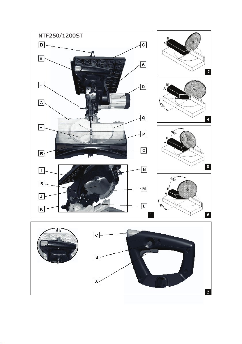
O Release lever
P Base
Q Support
R Main body
S Upper table locking knob
1.3 MANUFACTURER – IDENTIFICATION
Interskol Power Tools S.L.
Carretera de Sant Joan de les Abadesses s/n17500
RIPOL, (Girona), SPAIN
Tel +34972700200 - Fax +34972700554E-mail:
e-mail: felisatti@interskol.es
2 TECHNICAL CHARACTERISTICS
A sturdy, high-reliability structure ensures that these
mitre saws will be able to cut wooden boards and
PVC and aluminium pipe in industrial environments
at no expense to the machine essential handiness
or portability. All models are equipped with spacious
upper tables that permit the mitre saw to be easily
transformed into a disk saw to perform cuts of up to
40 mm thickness, engraving, facing, and trimming.
Only one operator is required for the use of the mitre
saw, which has been designed and constructed in
compliance with Standard EN 61029. All models are
equipped with release switches featuring LOCK in
‘ON’ buttons. All models come with minimum voltage
circuits that prevent the accidental restarting of the
machine after interruptions in power supply because
in such cases the operator is always required to reset
work conditions; a high-power and high-efciency
asynchronous motor ensures silent operation at all
rpm levels. The machine also comes with a motor
brake that permits the blade to be stopped within 10
seconds of the release of the button on the switch.
1.2 MITRE SAW IDENTIFICATION
Plate A (g. 1) provides mitre saw model information
and technical data of the motor and of its manufacturer;
Plate B provides mitre saw model identication.
1.2.1 IDENTIFICATION (g. 1)
A Data plate
B Logotype plate
C Upper table
D Movable upper casing
E Handgrip
F Machine lock pin
G Lower support stroke-end raised section
H Turntable
I Fixed casing
J Blade
K Machine lock knob 0°- 45°
L Turntable lock knob
M Movable lower blade protector
N Upper table ne adjustment

2.1 TECHNICAL DATA
Model NTF250/1200ST NTF305/1600ST
Tension and current V / A 230V-5,5A 230V-8A
Frequency Hz 50 50
Absorbed power W 1200 1600
Idling speed /min 4500 4000
Cut at 90°/crop (AxB g. 3) mm 73x150 102x150
Cut at 45°/crop (AxB g. 4) mm 73x90 97x102
Cut at 45°/blade at 45° (AxB g. 6) mm 46x150 66x150
Cut at 45°/blade at 45° (AxB g. 6) mm 45x48 45x53
Cut on upper table mm 40 66
Upper table dimensions mm 473x312 473x312
Blade diameter mm 250 305
Blade hole diameter mm 30 30
Weight kg 22 25
Overall dimensions (LxHxW) mm 520x396x650 573x432x667
Sound pressure emitted Lpa dB(A).(*) 91 96
Sound power emitted Lwa dB(A).(*) 104 109
Vibration level m/s2 (*) 1,0 (<2,5) 0,7 (<2,5)
* Reliefes enforced by the standard: EN 61029
2.2 STANDARD ACCESSORIES
This series of mitre saws is supplied complete with
the following set of standard accessories:
Adjusting rod (g. 7): required for the cutting of beams
of the same length.
Pusher For the working of small parts on the upper
table (g. 20).
Blister pack of Allen wrenches.
Important: the equipment provided may vary
according to the sales campaign in progress.
2.3 ACCESSORIES AVAILABLE ON REQUEST
The following accessories for particular work
conditions are also available on request:
Rapid clamp: (g. 8) permits the tighter locking of
bars and sections without vibration.
Foldable and movable universal support for mitre
saws (A g. 19).
Support and roller unit (B g. 19) for jutting piece
Vacuum unit (C g. 19) with connection tube and
spout.
Goniometer: to make angled cuts on the upper
table
(g. 21).
Workpiece support stroke-end raised section (G
g.1
WARNING! The use of accessories or attachments
other than those recommended in this manual may
pose risk of injury.
2.4 SAFETY DEVICES
In rest position, the blade is completely protected
by two xed casings and one movable casing with
opening that is automatically triggered by the lowering
of the blade unit during the execution of the cut.
On the upper table, the blade is protected by a casing
that is raised over the workpiece as it approaches the
cutting point.
WARNING! Never remove these protective casings
that enable the operator to work in conditions of
safety.
WARNING!
CHECK ALL DAMAGED PARTS
• All the parts of the tool should be carefully checked
before use in order to make sure that they will work
correctly for the operation foreseen.
• Check the alignment and assembly of all moving
parts for signs of breakage and any other conditions
that might compromise operation.
• Damaged protective casings and/or other parts
should be replaced by an authorised service center
unless indicated otherwise in this manual.
• Have defective switches replaced by an authorised
service center.
If the LOCK in “ON” button has not been pressed,
the blade automatically stops when the starting
lever switch in the handgrip is released.
WARNING!
Pressing the LOCK in “ON” button disables the safety
feature provided by the Manufacturer in the starting

lever switch. We recommend using this device only
with the greatest caution.
Although this tool has been designed and
constructed in order to permit operators to work
in the greatest conditions of safety, the following
precautions must be taken in particular work
conditions:
Adequate safety gloves and protective
eyewear.
The tool has been designed and constructed to
reduce noise to minimum levels (see technical data
2.1). In particular working conditions the maximum
sound level at the place of work may exceed 85 Db(A)
and therefore create a risk to health and hearing.
In this case the operator must use ear
protectors.
Work carefully and maintain the tool in perfect working
order, for your own safety.
2.4.1 SWITCH (g. 2)
Although the switch on your mitre saw prevents
accidental starting, a LOCK in “ON” button has been
provided. Respect the warnings provided in Point 4.4.
Switch operation
- Starting - To start the machine, press the lever
switch A and keep it pressed (g. 2)
- Lock in “ON” - The switch can be locked in “ON”
position by rst pressing the lever switch A to start the
motor and then pressing the LOCK in “ON” button B
(g. 2)
Warning! In order to release the switch, press the
black lever A and then release it. (g. 2)
Protection – The switch is equipped with a airtight
protection that provides protection against penetration
by dust and foreign bodies in general.
3 GENERAL SAFETY STANDARDS
WARNING! Read all instructions. Failure to follow
all instructions listed below may result in electric
shock, re and/or serious injury.
The term “power tool” in all of the warnings listed
below refers to your mains operated (corded)
power tool or battery operated (cordless) power
tool.Electrónica constante (mod. AF125/1100VES)
SAVE THESE INSTRUCTIONS
1) WORK AREA
a) Keep work area clean and well lit. Cluttered and
dark areas invite accidents.
b) Do not operate power tools in explosive
atmospheres, such as in the presence of ammable
liquids, gases or dust. Power tools create sparks
which may ignite the dust or fumes.
c) Keep children and bystanders away while
operating a power tool. Distractions can cause you
to lose control.
2) ELECTRICAL SAFETY
a) Power tool plugs must match the outlet. Never
modify the plug in any way. Do not use any
adapter plugs with earthed (grounded) power tools.
Unmodied plugs and matching outlets will reduce
risk of electric shock.
b) Avoid body contact with earthed or grounded
surfaces such as pipes, radiators, ranges and
refrigerators. There is an increased risk of electric
shock if your body is earthed or grounded.
c) Do not expose power tools to rain or wet conditions.
Water entering a power tool will increase the risk of
electric shock.
d) Do not abuse the cable. Never use the cable for
carrying, pulling or unplugging the power tool. Keep
cable away from heat, oil, sharp edges or moving
parts. Damaged or entangled cables increase the risk
of electric shock.
e) When operating a power tool outdoors, use an
extension cable suitable for outdoor use. Use of a
cable suitable for outdoor use reduces the risk of
electric shock.
3) PERSONAL SAFETY
a) Stay alert, watch what you are doing and use
common sense when operating a power tool. Do
not use a power tool while you are tired or under the
inuence of drugs, alcohol or medication. A moment
of inattention while operating power tools may result
in serious personal injury.
b) Use safety equipment. Always wear eye protection.
Safety equipment such as dust mask, non-skid safety
shoes, hard hat, or hearing protection used for
appropriate conditions will reduce personal injuries.
c) Avoid accidental starting. Ensure the switch is in
the off position before plugging in. Carrying power
tools with your nger on the switch or plugging in
power tools that have the switch on invites accidents.
d) Remove any adjusting key or wrench before turning
the power tool on. A wrench or a key left attached to a
rotating part of the power tool may result in personal
injury.
e) Do not overreach. Keep proper footing and balance
at all times. This enables better control of the power
tool in unexpected situations.
f) Dress properly. Do not wear loose clothing or
jewellery. Keep your hair, clothing and gloves away
from moving parts. Loose clothes, jewellery or long
hair can be caught in moving parts.
g) If devices are provided for the connection of dust
extraction and collection facilities, ensure these are
connected and properly used. Use of these devices
can reduce dust related hazards.
4) POWER TOOL USE AND CARE
a) Do not force the power tool. Use the correct power
tool for your application. The correct power tool will
do the job better and safer at the rate for which it was
designed.
b) Do not use the power tool if the switch does not turn
it on and off. Any power tool that cannot be controlled
with the switch is dangerous and must be repaired.
c) Disconnect the plug from the power source before
making any adjustments, changing accessories, or
storing power tools. Such preventive safety measures
reduce therisk of starting the power tool accidentally.
d) Store idle power tools out of the reach of children

and do not allow persons unfamiliar with the power
tool or these instructions to operate the power tool.
Power tools are dangerous in the hands of untrained
users.
e) Maintain power tools. Check for misalignment
or binding of moving parts, breakage of parts and
any other condition that may affect the power tools
operation. If damaged, have the power tool repaired
before use. Many accidents are caused by poorly
maintained power tools.
f) Keep cutting tools sharp and clean. Properly
maintained cutting tools with sharp cutting edges are
less likely to bind and are easier to control.
g) Use the power tool, accessories and tool bits
etc., in accordance with these instructions and in
the manner intended for the particular type of power
tool, taking into account the working conditions and
the work to be performed. Use of the power tool for
operations different from intended could result in a
hazardous situation.
5) SERVICE
a) Have your power tool serviced by a qualied repair
person using only identical replacement parts.
This will ensure that the safety of the power tool is
maintained.
4 INSTALLATION
4.1 PACKING AND UNPACKING
The mitre saw, complete with its accessories and
instructions for use ts inside a package and is locked
in position for transport.
WARNING! During transport the upper of the blade
must be covered by the upper protection or set in its
lowest position.
WARNING! Before using the tool, release the knob A
and the respective self-locking nut (g.12) previously
locked in position for the transport of the mitre saw
(see also Point 5.2).
4.2 LIFTING
The mitre saw must be lifted using the equipment and
safety measures adequate for the operation. The
mitre saw can be moved manually, provided that at
least 2 people are assigned to the task. Install the
mitre saw on a solid and sufciently level surface at
the ergonomically correct working height.
WARNING! Never lift the machine up by its protective
casings.
4.3 INSTALLATION
Room conditions, such as temperature, humidity,
illumination, general cleanliness and the correct
position of the mitre saw are all very important for
the safety of the operators and the performance of
the mitre saw itself. Also make sure that the tool is
securely fastened to the work bench.
4.4 ELECTRIC CONNECTION
Before connecting the machine to the power mains,
make sure that the electric system corresponds to the
regulations in force in the nation of use (with the
presence of a ground system, thermal cutout,
overload cutout) and that the voltage and frequency
correspond to the indications provided on Plate A (g.
1). Before using any extension cables, make sure that
the section of the cable is adequate to its length and
that a grounding connection is provided. Whenever
coiled extension cables are used, make sure that
they are completely uncoiled in order to prevent the
risk of overheating.
WARNING! The starting switch on these tools is
provided with a LOCK in “ON” button that permits
prolonged use (only when the tool is used as a
disk saw, however) without requiring the starting
switch to be pressed constantly. Before plugging
the tool plug into the socket, make sure that the
starting switch is set in the unlocked position.
Whenever the tool will not be used for some time,
always remember to switch it off and leave the
lever in released position.
4.5 WORK PLACE
The tool that you have purchased is a movable power
tool that requires only one operator for use thanks
to its conformation, weight, and handiness. Under
conditions of normal use, the operator standing in
front of the machine has the handgrip in front of him.
5 REGULATION – MITRE SAW SQUARING
The mitre saw is delivered by the Manufacturer
after regulation and squaring performed to standard
parameters.
Squaring can be adjusted whenever required (see
Points 5.4 - 5.7).
WARNING - Always unplug the plug from the socket
before proceeding to any regulation operations on the
mitre saw.
5.1 BLADE UNIT LIFTING
An assembly of internal springs keeps the blade unit
raised in rest position. In this position, a safety catch
prevents the accidental operation of the blade unit.
5.1.1 In order to release the blade unit and permit the
use of the machine as a mitre saw, press the orange
key C on the handgrip (g. 2) (this operation can be
performed by keeping your right hand steady on the
handgrip).
5.1.2 In order to use the machine as a disk saw,
release the blade unit as shown in 5.1.1, and after
lowering the unit completely, lock it in place with the
pin F (g. 1). In this position, the oscillation of the blade
unit can be reduced by using the knob A (g. 12).
Remember to return the knob to its original position
whenever the machine must be used as a mitre saw
(unscrew up to the position dened by the self-locking
nut).
5.2 BLADE PENETRATION DEPTH REGULATION
(g. 12)
The blade penetration depth has already been set by
the Manufacturer during nal testing. Due to the
fact that incorrect regulation prematurely dulls blade
sharpness and/or may break blade teeth, additional
regulation might be required by proceeding as follows:
- Turn the knob A and the respective self-locking
nut in order to set a limit on the descent of the motor

support and prevent the blade from coming into
contact with the turntable.
WARNING! After this operation has been comp-leted,
make sure that the blade has not come into contact
with the turntable and that the self-locking nut is
tightly screwed down.
5.3 REGULATION OF THE SPLITTING WEDGE
(g. 13)
WARNING! The splitting wedge must never be
thicker than the width blade cutting width and never
thinner than the blade body.
When using the upper table, the splitting wedge
prevents the stopping of the blade caused by the
excessive pressure of the surfaces during cutting.
Whenever such regulation is necessary, proceed as
follows:
- Remove the upper protective casing over the
blade unit.
- Remove the upper table.
- Using a 10 mm Allen wrench, unscrew the
hexagonal head screw A (g.13).
- Adjust the splitting wedge until it stands approx. 5
mm `from the blade and 5 mm lower than the blade.
- Tighten all the screws again and lower the
protective casing.
5.4 REGULATION OF THE BLADE UNIT
COMPARED TO THE WORK SURFACE
90° regulation
- Lower the head of the machine and lock it in place
using the corresponding pin F (g. 1).
- Position the square A as shown in gure 14-b and
adjust the squaring using the dowel C (g. 12).
5.5 REGULATION OF THE TURNTABLE (g. 14)
0° regulation
- Lower the head of the machine and lock it in place
using the corresponding pin F (g. 1).
- Position the turntable on “0”.
- Unscrew the support screws.
- Position the square A between the blade and
support
as shown in the gure.
- Keeping the turntable positioned on “0”, adjust the
support using the corresponding dowels C until a
reading of 90° is shown on the square.
- Tighten all the support screws unscrewed
previously.
5.6 REGULATION OF VERTICAL SURFACE
STROKE END (0° - 45°) (g. 15)
- Lower the head of the machine and lock it in place
using the corresponding pin F (g.1)
- Position the turntable on “0” and lock it in place;
remove the stroke end raised section G (g. 1)
(when present).
- Position the head of the machine at 45° by
unscrewing the knob E (g. 11) and then position
the square A as shown in gure 15.
- Regulate to 45° using the dowel B.
5.7 REGULATION OF HORIZONTAL SURFACE
STROKE END (-45° 0° +45°)
Adjust the screw A (g. 11) to create a stroke end
point for the turntable when the 45° reading on the
turntable matches the same reference index on the
base. Repeat the operation at the symmetrical 45°
reading with the screw on the opposite side of the
base.
6 OPERATION AND USE
6.1 CUTTING SPEED
The type of material and types of cut possible with
the series of mitre saws is vast indeed. The operator
must select the blade to use on the basis of the
material, the cutting speed, and advance of the blade.
Reference to the values above are provided in the
table.
6.2 CUTTING WITH THE BLADE AT 90° AND
TURNTABLE ROTATED (g. 4)
(RI and NTF305 version)
- Release the turntable H (g. 1) by keeping the lever
N (g. 1) pressed down – Rotate the turntable and
select the desired cutting angle using the graduated
scale and then release the lever B. Note: pre-xed
cutting angles are available (0° ±15° ±22°30’ ±30°
±45°) at which the turntable can be locked. We
recommend locking the turntable into position with
the use of the locking knob L (g. 1).
(RP version)
- Release the turntable H (g. 1) using the locking
knob L - Rotate the turntable and select the desired
cutting angle using the graduated scale.
Note: thanks to the “CLIC-CLAC” function, the
turntable automatically locks itself into place at
various pre-xed cutting angles (0° ±15° ±22°30’
±30° ±45°). After locking into position, the application
of a slight pressure is sufcient to rotate the turntable.
Lock the turntable into place using the locking knob L
(g. 1) prior to cutting.
6.3 CUTTING WITH THE BLADE INCLINED AND
THE TURNTABLE POSITIONED AT 0° (g. 5)
WARNING! Remove the support stroke-end raised
section G (g. 1) (when present) before proceeding
to the operation below.
- Release the blade unit by unscrewing the knob
E (g. 11) – Rotate the blade unit and select the
desired cutting angle using the graduated scale,
and then lock into the knob E into position again.
WARNING! Make sure that the support has been
securely fastened with the use of the knob E (g. 11)
when making inclined cuts (g.5-6).
6.4 USE AS MITRE SAW
WARNING! - Make sure that the switch key B (g. 2)
is in the release position (protruding).
- Bring the upper table to its maximum permissible
height and make sure that the blade is completely
protected by the upper casing – Fasten the material
to be cut securely to the cutting surface.
WARNING! Make sure that the blade is completely
protected by the upper casing.
WARNING - The use of the clamp is absolutely
required whenever aluminium sections must be cut.
WARNING - Excessive pressure on the handgrip

does not provide shorter cutting times and can lead
to diminished efciency caused by the overloading of
the motor.
6.4.1 STARTING AND STOPPING THE BLADE
- Start the blade by pressing the tool lever A (g. 2)
and then wait until the blade reaches its maximum
rpm. - Lower the blade unit gradually and then
make the cut desired. After the cut has been made,
release the lever A (g. 2) and then wait until the
blade has come to a complete stop.
WARNING - Make sure that the movable protective
casings are all in correct position whenever the blade
is raised in rest position. The machine is provided
with a release button for the starting and stopping
of the blade. This button can be locked in “ON” by
pressing the switch black key B when the switch
black lever A is at the end of its stroke and the motor
is running (g. 2).
WARNING - This Lock in ”ON” button disables the
safety provided by the Manufacturer in the starting
lever switch. We recommend using this device only
with the greatest caution and only when the tool is
being used as a disk saw. In order to release the
switch, press the black lever A and then release it.
6.5 USING THE STROKE END RODS (g. 7)
Proceed as follows to use the stroke end rods: - Insert
the rod A in the hole of the workpiece support and lock
it in place with the corresponding knob B – Loosen
the knob C and adjust the rod D as required by the
length of the workpieces by using the millimetre ruler
for reference. Then lock the knob C back into position.
6.6 USING THE CLAMP (g. 8)
Proceed as follows to use the clamp:
- Insert the pin A in the corresponding slot B and lock
it in place with the dowel C located in the rear part of
the workpiece support
– Insert the clamp D on the pin A and lock it in place
at the desired height using the wing nut E
– Lock the piece to be cut into place by tightening
the upper knob F.
6.7 USING THE UPPER TABLE AS A DISK SAW
WARNING - The use of the upper table for the cutting
of steel and aluminium is absolutely prohibited.
- Never use the tool to make slots.
Proceed as follows to use the upper table: - Make
sure that the switch is not locked in “ON” - Completely
lower the blade unit and lock it in place using the pin
F (g. 1)
(RI and NTF305 version)
– This version is equipped with ne-adjustment:
adjust the height of the upper table using the knob N
(g. 1) and then lock the table in position by tightening
the knob S (g. 1).
(RP version)
- Adjust the height of the upper table as required by
the piece to be cut, and then lock in position using the
corresponding knobs S (g. 1) and T (g.9).
6.7.1 STARTING AND STOPPING THE BLADE
- Start the blade by pressing the tool lever A (g. 2)
and then press the black key B (g. 2) and wait until
the blade reaches its maximum rpm. - Make the cut
desired.
After the cut has been made, press the lever A (g. 2)
and then release it and wait until the blade has come
to a complete stop.
6.8 USING THE STROKE-END GUIDE FOR THE
UPPER TABLE (g. 9)
Proceed as follows: - Insert the guide G (g. 9) in the
upper table – Select the desired cutting width using the
graduated scales – Lock into the guide G into position
using the knob H.
6.9 CUTTING SMALL PIECES
Small pieces must be worked with the use of the correct
tools – On the lower table: Use the clamp to lock the
workpiece in place and the stroke-end rods to obtain the
size desired – On the upper table: Use the pusher (g.
20) provided to advance the workpiece.
Never put your hands on the workpiece to be cut.
Keep the pusher in a safe place nearby for use
whenever required.
6.10 CUTTING LARGE PIECES
Never remove the workpieces that have already been
cut or other parts of the workpieces to be cut while the
machine is working and the support is not in rest position.
WIDIA BLADES MATERIAL BLADE Ø – No. TEETH /min
Ø 250 mm - Z 24 4500
WOOD
PVC Ø 250 mm - Z 60 4500
ALUMINIUM
FRAMES Ø 250 mm - Z 80 4500
Ø 250 mm - Z 40 4500
Ø 250 mm - Z 60 4500
Ø 305 mm - Z 72 4000
Ø 250 mm - Z 60 4500
Ø 305 mm - Z 72 4000

6.11 IMPROPER USE
The functions and use of this tool are those exclusively
indicated in this manual. Never use the tool to cut thick
tree trunks or branches.
Any other use of the tool is explicitly forbidden.
-Never cut aluminium or steel on the upper table.
-Always use sharp blades appropriate to the type
of cuts to be made.
-Never use the machine without the protective
devices described.
-Never use the machine for food-processing
purposes.
-Use only the right types of blade (see Table, Point
6.1) for the material to be cut: wood, aluminium
sections, PVC pipe, etc.
The cutting of any other type of material not
specied in this manual is expressly prohibited.
The machine comes with a brush that conveys
all dust into the suction area in order to limit the
quantity of dust generated during cutting.
WARNING! Whenever wood is cut, connection to an
external vacuum unit must be used in order to lower
the risk of exposure to dust.
Always wear dust-proof face masks.
7 MAINTENANCE
WARNING - Always unplug the plug from the power
supply socket before performing.
maintenan
Note: operating noise can be decreased by
using the right blades and performing frequent
maintenance on the blade and mitre saw itself.
7.1 LUBRICATION
The mitre saw is delivered already completely
lubricated and does not require any further lubrication.
7.2 ROUTINE CLEANING
WARNING - Avoid touching the handgrip with hands
that are dirty with oil or grease, and immediately
clean the handgrip whenever this happens.
- Clean the machine carefully after use by spraying
with compressed dry air.
WARNING - An attachment that can be easily
connected to any Felisatti vacuum unit is provide to
improve work conditions.
7.3 CHECKING THE DRIVE BELT
These machines are equipped with drive belts.
The right tightness of these belts is essential to
good operation and must be checked regularly and
adjusted whenever necessary by proceeding as
follows:
- remove the casing over the belt A (g.16) and
loosen the 4 screws C (g. 17) that keep the motor
unit in place.
- adjust the tightness of the belt using the
corresponding dowel B (g. 17).
- tighten the 4 screws C (g. 17) in order to lock the
motor unit in place and reassemble the protective
casing ove the belt.
WARNING! The failure to perform this operation
regularly may result in damage to the belt and
incorrect machine operation.
7.4 DISPOSAL
At the end of the machine working life, or
when it can no longer be repaired, ensure
that it is disposed of according to the standard
regulations of the country in which it is being used,
and that the disposal operation is carried out by
specialised personnel following authorised guidelines.
In all circumstances:
- Do not abandon in the environment;
- Do not dispose of together with solid urban
waste products;
- Contact the special recycling centers
8 PART REPLACEMENT
WARNING! - Always unplug the plug from
the power supply socket before replacing
spare parts.
8.1 BLADE REPLACEMENT (g. 18)
Proceed as follows to replace the blade:
Raise the upper table to its highest permissible height
- Release the movable protective casing L (g. 1) by
using the button B and raise it completely - Using the
two Allen wrenches supplied (on the blade side and
on the motor side) unscrew the screw C clockwise -
Remove the locking ange D, remove the blade by
rst sliding it to the left and then sliding it downwards -
Mount the new blade after making sure that the teeth
face the direction indicated by the arrow and then lock
it in place by screwing the screw C counter-clockwise
tightly down - Lower the movable protective casing L
by returning button B to its original position and then
make sure that the blade is protected when the blade
unit is completely raised.
WARNING! - Use only the blades recommended by
the Manufacturer and in compliance with Standard
EN 847-1. Make sure that the speed marked on the
blade is greater than the tool rated speed.
WARNING! - NEVER USE STEEL BLADES FOR
HIGH SPEEDS.
8.2 REPLACING THE POWER SUPPLY CABLE
Make sure that the power supply cable is in good
condition; if worn, have it replaced by an authorised
Assistance center.

9 PROBLEMS-CAUSES-REMEDIES
PROBLEMS CAUSES REMEDIES
The motor fails to work Defective motor, power supply
The motor starts slowly or does
not reachoperating speed.
Chipped or irregular cuts The blade is dull Sharpen or change the blade.
Step cut or irregular cutting
surfaces.
MITRE SAW:
Cuts not made at the desired
angle.
UPPER TABLE:
Difculty in cutting.
Crooked trimming. The guide is not parallel to the
Protective casings or moving
parts jammed.
The motor fails to start when the
starting button is pushed.
The blade stopping times lasts
longer than 10 seconds.
cable or plug. Fuses blown
Low power supply voltage.
Damaged motor windings.
Condenser burnt out
Inadequate blade
Worn-out or defective blade.
Inadequate squaring. Clean the stroke-ends.
Blade – splitting wedge out of
alignment.
blade.
Chips or dirt have not been
removed.
Switch malfunction.
Cables disconnected or broken.
Condenser malfunction.
Electronic module malfunction. Contact authorised Assistance
Have the machine checked by
pecialised personnel.
Never try to repair the motor
yourself because of the potential
danger involved.
Check the fuses and replace them
ifnecessary.
Have the voltage checked by the
power supply provider.
Have the motor checked by
specialised personnel.
Have the condenser changed by
specialised personnel.
Replace the blade with a more
appropriateblade.
Change the blade.
Adjust the turntable and the
stroke-ends.
Regulate the splitting wedge
and the protective casing xing
bracket.
Align guide and blade.
Perform a thorough cleaning by
spraying
compressed dry air.
Contact authorised Assistance
centers.
centers.
DECLARATION OF CONFORMITY
We hereby declare, under our sole responsibility,
that the FELISATTI brand products described in
this manual comply with the following standards or
standard documents: Standard EN 61029, Machine
Directive 98/37/EC and amendments, with 2006/95/
EC and 93/68/EEC, and in regard to electromagnetic
compatibility, with Directive 89/336/EEC, EN 55014.1,
EN 55014.2, EN61000.3.2 and EN 61000.3.3 and EN
50366.
Jordi Carbonell Santiago Lόpez
We reserve the right to make technical changes.

Interskol Power Tools S.L.
Carretera de Sant Joan de les Abadesses s/n17500 RIPOLL, (Girona), SPAIN
Tel +34972700200
Fax +34972700554
e-mail: felisatti@interskol.es
 Loading...