


FUSIONE-HS-2

WARNING
All applicable national and local codes must be followed when installing and operating the
equipment detailed in this manual.
FAILURE TO ABIDE BY THESE CODES AND THE SPECIFICATIONS DESCRIBED IN
THIS MANUAL CAN RESULT IN SERIOUS INJURY TO PERSONNEL AND/OR DAMAGE
TO THE EQUIPMENT!
Any questions regarding the contents of this document or any related matter should be
directed to FEC INC. at (586) 781-2100, faxed to (586) 781-0044 or emailed to:
support@fec-usa.com.
The information set forth in the following document is the property of FEC INC.
This document shall not be released to or copied for any person and/or organization
With out the expressed prior consent of FEC INC.
Unauthorized reproduction or distribution of this manual is strictly prohibited.
Please contact FEC INC. if you require additional copies.

Revision History
Revision
date
Manual No. Content of Revision
2005/July First Edition
2007/August FUSIONE-HS-2 Revision 2 - Updated format & added relevant information
2008 / June FUSIONE-HS-2
2008 / July FUSIONE-HS-2
DSP1500 = Servo Press
DSP1500 = Servo Press
AFC1500 = Nutrunner
AFC1500 = Nutrunner
FUSION = DC Hand Tool
FUSION = DC Hand Tool
E = English Version
S = Spanish Version
*Japanese Version furnished by DDK uses
DDK numbering convention.
Original Operation Manual
MINOR Revision – Chapter 2 – Page 2-4 (Chapter Rev. 2.1 now)
Updated Power Consumption (Running & Idle)
MINOR Revision – Chapter 4 – Page 4-48 – 4-53 (Chapter Rev.2.1 now)
Added DeviceNet Interface
Manual Numbering Convention
FUSIONE-HS-2
Version Number
(Major Revision Level)
HS = Controller unit Hardware
Operation Manual
HM = Multi / Main Unit Hardware
Operation Manual
HM-ENET = Ethernet Manual for
Multi / Main Unit
SW = Software Manual

Thank you for purchasing our Electric Servo Nutrunner – FUSION System.
Introduction
This instruction manual describes the procedures for installation, wiring, and handling,
and actions to be taken in case of any failure.
This instruction manual shall be delivered to the end user who operates the equipment.
Read all instructions before use, and always keep this instruction manual with the equip-
ment.
Items not described in this instruction manual shall be considered “unavailable”.
The product specification and appearance described in this instruction manual is subject
to change without notice.
All rights reserved. Any disclosure, copying, distribution, or use of the information con-
tained herein for other than its intended purpose, is strictly prohibited.
For the safety of operator and equipment
It is important for you to read all “Safety Precautions” before using the equipment, and under-
stand and observe all instructions and recommendations included in this manual.
Read all instructions and recommendations included in this manual, understand the functions
and performance of this nutrunner, and correctly use this equipment.
Wirings and parameter settings shall only be conducted by a qualified professional.
Never conduct a withstand voltage test or insulation resistance test on this equipment.
Indicate the following on all instruction manuals that use this equipment.
”This equipment is capable of high voltages hazardous to human life.”
Points to check when unpacking
Please confirm the followings when unpacking this equipment.
Ensure that you received the correct model, as ordered.
Ensure that there are no missing parts.
Check for any damage caused during transportation.

Warranty
Introduction
Warranty Period
The standard warranty period is one year from the date of purchase or one year from delivery to
the designated End User (not to exceed 18 Months). Actual terms are order specific.
Provision of warranty
If your product proves to be defective, although it has been used properly in accordance with
this instruction manual, during the period of warranty, this product will be repaired free of
charge.
However, in the following cases, the customer will be required to pay for repair charges, even for
defects occurring within the warranty period.
1. Any defect due to improper conditions, improper circumstances, and improper handling.
2. Any defect due to modifications or repairs performed by the customer.
3. Any defect caused by other equipment.
4. Any defect caused by customer failing to meet the equipment’s specification.
5. Any defect due to natural disasters and accidents.
This warranty shall be limited to repairing or replacing this product. Any liability for indirect or
consequential loss or damage of any kind incurred or suffered by the customer due to a defect
of the product is excluded.

R
ead all instructions before operating the
instruction
ments functions, safety precautions and
[Warning] and [Caution].
To prevent danger to the user and other persons as well as property damage
observed are marked with the symbols below.
This instruction manual uses the
that may be caused when the instruction is not observed.
nstructions that are marked with
are not observed according to conditions.
marked with the above symbols are very
and especially those
the following additional
Safety Precautions
This symbol indicates that failure to observe instruction mar
with this symbol
This symbol indicates that failure to observe instruction marked
with this symbol
damage.
Warning:
Electric shock
Caution:
equipment safely and
the equi
. Safety precautions in this manual are
nstruction
two symbols according to the degree of damage
may result in severe damage if they
instructions. For your safety, f
s that shall be
may result in severe personal injury or death.
personal injury or
Caution
Warning:
F
ire
Caution:
Electric shock
Caution:
High
Temperature
correctly. Prior to use, read this
marked with two symbols
equipment in order to use this
manual carefully and fully understand
instructions
p-
must be fully
Warning
Caution
Even i
Contents
low all instructions
, i
following
marked with these symbols.
may result in minor
important
s that
ked
material
ol-
This instruction manual uses
observed.
Fire
Prohibited
Required
symbols for instruction
Do not disassemble
Ground
Do not remove the motor
tool output spindle may rotate and cause injury.
Do not repair, disassemble, or modify the equipment
Never operate the eq
flammable gases
Keep fingers away from the
ter the equipment is turn
operation and maintenance work shall be conducted by a
Turn OFF the power when conducting wiring operation
damage the cables, apply excess
Never use damaged cables.
Properly GROUND all Field Ground (
pin on the POWER CORD.
power cord grounded!
abnormal odor, noise, or operation error
power
Install a Power shutdown
When equipment is automatically operated, i
der to stop
Keep away from the equipment
measures are conducted
while power is applied.
individual components of the system.
injury, electric shock, fire, and malfunction.
corrosive
fire.
connectors while the equipment is turned ON
this instruction may cause
qualified
maintenance
the cables.
including the ground
operate this equipment without the ground pin on the
stop operation
this instruction may cause
in order to ensure the safety of equipment.
rgency stop circuit
may cause
recovery from a temporary blackout
he equipment may
Safety Precautions
Warning
s and gear cases of tools
The
.
Failure to observe
or
shock.
Wiring,
Failure to observe
Failure to observe
Never
Failure to observe
Failure to observe
In case of an
and turn OFF the
Failure to observe
equipment in or
Failure to observe
this instruction may cause
uipment where it is exposed to water, near a
. Failure to observe this instruction may cause
ed OFF. Failure to observe
this instruction may cause electric shock and injury.
and
this instruction may cause electric shock and injury.
stress to cables, or squeeze
this instruction may cause electric shock and fire.
FG) Connections and terminals
NEVER
this instruction may cause electric shock.
occurrence,
source. Failure to observe
device
this instruction may cause injury.
nstall an eme
operation promptly. Failure to observe this,
during
after restarting the equipment. T
this instruction may cause injury.
.
atmosphere
and for a while af-
electric
professional.
.
immediately
injury and fire.
on the outside of
injury.
, and ensure safety
suddenly restart.
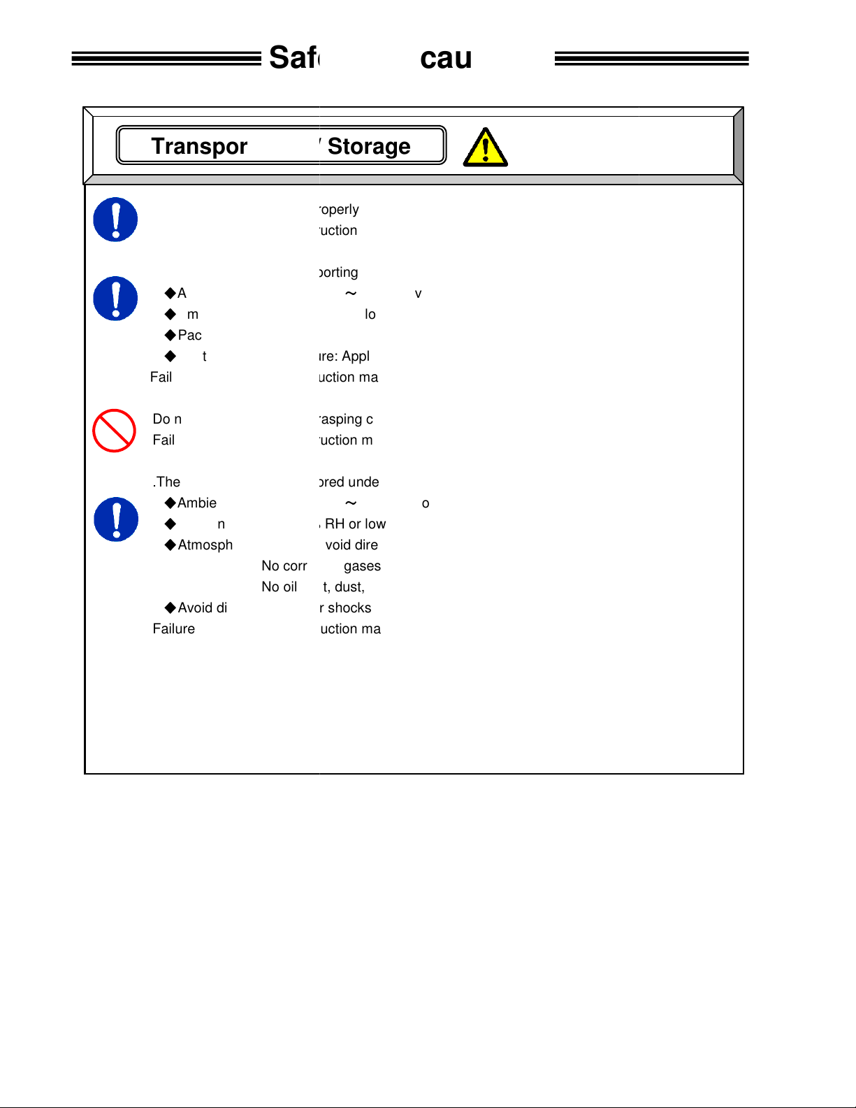
Transport the equipment properly according to its weight.
this instruction may cause
The conditions when transporting the equipment by ship is as below.
-
0% RH or lower
Rust prevention measure: Apply
this instruction may cause
transport tools by grasping cables
this instruction may cause
The equipment shall be stored under the following conditions.
-
Ambient humidity: 90% RH or lower
Indoors (Avoid direct sunlight)
corrosive gases or flammable gases
No oil mist, dust, water, salt, iron powder
Avoid direct vibration or shocks
this instruction may cause
Transportation / Storage
Safety Precautions
Caution
Failure to observe
Ambient temperature:
Ambient humidity: 5
Package: Tight seal
Failure to observe
Do not
Failure to observe
.
Ambient temperature:
Atmosphere:
Failure to observe
injury and malfunction.
5°C+55°C (Avoid freezing)
(Avoid moisture)
light oil on steel portion of tools.
earth leakage and malfunction.
.
injury and malfunction.
5°C+55°C (Avoid freezing)
(Avoid moisture)
No
a ground fault and malfunction.

or provide torque reaction for
Failure to observe
Make sure controller is firmly mounted and will not come lose or fall during operation
Failure to observe
The power source shall be provided with safety measures
use tools or
Failure to observe
Do not subject the
Failure to observe
)
ailure to observe
Operate the equipment within the specified power supply voltage
Failure to observe
When operating the equipment in the following conditions,
the equipment.
where
where the equipment is subjected to
near a
Failure to observe
Installation / Wiring
where they can bear the maximum torque
injury and malfunction.
such as breakers
fire and malfunction.
or missing parts.
fire, injury, and malfunction.
, and malfunction.
injury, electric shock, fire, and malfunction.
sufficient
strong electric field
injury, false operation, and malfunction.
Caution
Safety Precautions
Install
operation.
circuit protectors.
Do not
Route all wiring(s
F
to shield
Location
Location
Location
all tools
this instruction may cause
this instruction may cause malfunction.
Failure to observe this instruction may cause
controller units that are damaged
this instruction may cause
equipment to excess shock and impact.
this instruction may cause malfunction.
) properly and firmly.
this instruction may cause injury, false operation
this instruction may cause
take
electrical noise is generated
a
high power wire.
this instruction may cause
during
.
and
.
measures
or magnetic field

equipment with wet hands
this instruction may cause electric shock.
Properly GROUND all Field Ground (
on the POWER CORD.
this instruction may cause
Use the equipment under the following conditions.
Ambient temperature: 0°C
Ambient humidity: 90% RH or lower
Indoors (Avoid direct sunlight)
corrosive gases or flammable gases
No oil mist, dust, water, salt, iron powder
Avoid direct vibration or shocks
this instruction may cause
ll parameters before operation
movement of the equipment.
this instructi
experience sudden torque reaction when operated by hand while
engaged to a part. Grasp tool firmly with firm footing when operating. Additionally, be sure
work piece is securely clamped from any movement during torqueing operations.
instruction
Do not turn ON and OFF the equipment repeatedly.
instruction
equipment at torque higher than
Failure to observe this instruction may shorten
due to the high temperature caused by overload.
In case any abnormality occurs,
and restarting the equipment.
Failure to observe this instruction may cause injury.
Operation
/ Adjustment
Safety Precautions
or while standing in a wet location
including the ground
operate this equipment without the ground pin on the
in order to prevent unexpected
and malfunction.
or cause malfunction
remove the cause and ensure safety before resetting
Caution
Never operate the
Failure to observe
pin
power cord grounded!
Failure to observe
Atmosphere:
No
Failure to observe
Confirm and adjust a
Failure to observe
The equipment may
the
Failure to observe this
FG) Connections and terminals
NEVER
electric shock.
+45°C (Avoid freezing)
(Avoid moisture)
a ground fault and malfunction.
on may cause injury, false operation
may cause injury.
.
Failure to observe this
Do not use the
may cause malfunction.
the maximum torque.
equipment life

Table of contents
Table of Contents
Chapter 1: Outline
1.1 About This operations manual 1-2
1.2 Features 1-3
1.3 Functions. 1-5
1.4 System requirements 1-6
Chapter 2: Specifications
2.1 Main Specifications 2-2
2.2 Duty Cycle Calculation 2-3
2.3 Controller Unit Specifications 2-4
2.4 Capability. 2-5
2.4.1 Nutrunner Tool Specification Table. 2-6
2.4.2 Nutrunner Decimal Point Display Table. 2-7
Chapter 3: System Description
3.1 Controller 3-2
3.1.1 Controller Part Number Breakdown 3-2
3.1.2 Controller Front Panel 3-4
3.1.3 Controller Back Panel 3-5
3.2 Fusion Tool 3-7
3.2.1 Fusion Tool Part Number Breakdown 3-7
3.2.2 Fusion Tool Control, Displays and Connectors 3-8
Page
1-1
2-1
3-1
Chapter 4: System Setup and Wiring 4-1
4.1 Design and Build Procedure 4-2
4.2 Component Dimensions 4-3
4.2.1 Controller Unit Dimensions 4-3
4.3 Unit Arrangement 4-4
4.4 Nutrunner (Tool) Dimensions 4-5
4.4.1 Straight Tool 4-5
4.4.2 Right Angle Tool 4-6
4.4.3 Pistol Tool 4-7
4.5 Connection Diagrams 4-9
4.6 Power Requirements and Connections 4-10
4.6.1 Controller Unit 4-10
4.7 Wiring PLC I/O 4-11
4.7.1 Explanation of Controller Unit I/O 4-12
4.7.2 Work / Parameter Select Table 4-13
4.7.3 Bank Select Table 4-14
4.7.4 Bank Output Servo Error Table 4-16
4.7.5 PLC Wiring Sample 4-17
4.8 RS-232 Data Communication Ports. 4-18
4.8.1 Front Panel DB9 PC Connection for AFC User Console Software 4-18
4.8.2 Rear Panel DB9 PC Connection (RS232) 4-19
4.8.3 Rear Panel RS232 Communication Protocol 4.20
4.8.4 Rear Panel RS232 Alternate Communication Protocol 4-24
4.8.5 Rear Panel RS232 Alternate Communication Protocol 4-25
4.9 Torque/Angle MON. DB9 (external monitoring connector). 4-26
i

Table of contents
4.10 Controller Unit DIP Switch setting. 4-27
4.10.1 Controller Unit DIP switch positions 1 ~ 3 4-27
4.10.2 Controller Unit DIP switch positions 4 ~ 8 4-28
4.11 Tool Connection (cabling) 4-29
4.11.1 Cable Installation Guidelines 4-30
4.11.2 Considerations for Cable Trolleys 4-31
4.11.3 Considerations for Flexible Cable Tracks 4-31
4.11.4 Considerations for Cable Trays and Ladders 4-31
4.11.5 Tool Cable - Preamplifier Connector. 4-32
4.11.6 Tool Cable - Motor Connector 4-32
4.11.7 Tool Cable - Resolver Connector 4-32
4.12 Firmware Flash Connector (CN8). 4-33
4.13 SYNC Connector 4-34
4.14 Options – Ethernet Card 4-35
4.14.1 Ethernet Set-up of PC to Communicate to Ethernet Module 4-36
4.14.2 Ethernet Module Connection 4-37
4.15 Options – Fieldbus Interfaces 4-38
4.15.1 Fieldbus Interfaces – Profibus-DP 4-39
4.15.2 Fieldbus Interfaces – Allen Bradley Remote I/O
4.15.3 Fieldbus Interfaces – DeviceNet
4-44
4-48
Chapter 5: Power Up and Initial Checks 5-1
5.1 Before Powering On 5-2
5.2 Initial Data Setting 5-3
Chapter 6: Fastening Instructions 6-1
6.1 Fastening Control 6-2
6.1.1 Torque Control Method 6-2
6.1.2 Angle Control Method 6-6
6.2 Monitoring Functions 6-12
6.2.1 Peak Torque Monitoring 6-12
6.2.3 Final Torque Monitoring 6-14
6.2.3 Angle Monitoring 6-16
6.2.4 Point-to-Point Torque Rate Monitoring 6-18
6.2.5 Time 6-20
6.3 Speed Functions 6-21
6.4 Reverse Functions 6-23
6.5 Torque Recovery 6-24
6.6 Added Functions 6-25
6.6.1 Current Monitor / Control 6-25
6.6.2 Angle Correction 6-26
6.6.3 Reduced Fastening Reaction 6-26
6.6.4 VariSpeed 6-26
6.6.5 Work (Batch Counting) 6-26
6.6.6 Torque Inhibit 6-27
Chapter 7: System Operations 7-1
7.1 Fusion Display and Programming Unit Operation 7-2
7.1.1 Manual Fastening controls 7-2
7.1.2 Fastening Indicators 7-3
7.1.3 Fastening Preset / Result displays 7-3
ii

Table of contents
7.2 Run State Modes. 7-5
7.2.1 Display indication modes. 7-5
7.2.2 Real-time display indication mode. 7-6
7.2.3 Fastening results display mode. 7-7
7.2.4 Parameter display mode 7-8
7.2.5 Parameter Data List & Data Explanation 7-9
7.2.6 Status Display 7-24
7.3 Download / Setup Mode Operation. 7-25
7.3.1 Download Mode selection 7-25
7.3.2 Setup Mode selection 7-26
7.3.3 Parameter Number Selection. 7-27
7.3.4 Data # selection 7-28
7.3.5 Data Edit Mode Operation 7-29
7.3.6 Parameter Copy 7-30
7.4 Calibration adjustment. 7-31
7.5 Optional Real Time Clock Module 7-32
7.6 Tubenut Head Setup 7-33
7.6.1 Recommended Parameter Setup for Tubenut Head 7-34
7.6.2 Tubenut Head Operation 7-35
Chapter 8: Maintenance and Inspection 8-1
8.1 Inspection Items 8-2
8.1.1 Nutrunner (Tool) 8-2
8.1.2 Tool Cable 8-2
8.1.3 Controller Unit 8-3
8.1.4 Auxiliary Tool Heads 8-3
8.2 Basic operational tests 8-4
8.2.1 Torque transducer. 8-4
8.2.2 Resolver. 8-4
8.2.3 Motor. 8-4
8.2.4 Transmission Disassembly and Inspection 8-6
8.3 Replacements 8-7
8.3.1 Controller Unit Replacement 8-7
8.3.2 Replace Nutrunner (tool) 8-8
8.3.3 Replace Homerun cables 8-8
Chapter 9: Troubleshooting 9-1
9.1 Abnormal Conditions. 9-2
9.2 Torque Transducer Abnormals. 9-3
Calibration Error 9-3
9.2.1 Code 1-0 Torque transducer / Zero Voltage error. 9-3
9.2.2 Code 1-1 Torque transducer / Cal Voltage error. 9-3
9.2.3 Code 1-2 Torque transducer / Zero check error. 9-4
9.2.4 Code 1-3 Torque transducer / Cal self-check error. 9-4
9.2.5 Code 1-4 Torque transducer / started on Zero condition error. 9-4
9.2.6 Code 1-5 Torque transducer / started on Cal condition error 9-4
9.2.7 Code 1-6 Torque transducer / Zero Level Self Check Error 9-5
9.3 Torque Over 9-6
9.3.1 Code 2-0 Torque Over Abnormal / Torque Inhibit High Limit 9-6
iii

Table of contents
9.4 Tool EEPROM Errors 9-7
9.4.1 Code 3-0 Preamplifier / Tool ID Checksum error 9-7
9.4.2 Code 3-1 Preamplifier / Tool type error 9-7
9.4.3 Code 3-2 Preamplifier / Started without tool connected 9-7
9.4.4 Code 3-3 Preamplifier / Tool is not connected 9-7
9.5 System Memory Errors 9-8
9.5.1 Code 4-0 system memory error / Flash ROM write error 9-8
9.5.2 Code 4-1 system memory error / Flash ROM read error 9-8
9.5.3 Code 4-2 system memory error / Servo Amp Flash ROM error 9-8
9.6 Servo Amplifier Response / Resolver 9-9
9.6.1 Code 5-0 Servo Amplifier reply error / No reply from Resolver 9-9
9.7 Servo Type Error 9-10
9.7.1 Code 6-0 Servo Type error / Servo Type mismatch 9-10
9.9 Servo Amplifier Error 9-11
9.9.1 Code 8-1 Servo Amplifier error / Servo is over heated 9-11
9.9.2 Code 8-4 Servo Amplifier error / Over current 9-11
9.9.3 Code 8-5 Servo Amplifier error /Internal power supply. 9-11
9.9.4 Code 8-6 Servo Amplifier error / Input Voltage abnormal 9-12
9.9.5 Code 8-9 Servo Amplifier error / Over speed. 9-12
9.9.6 Code 8-10 Servo Amplifier error / over load ( I square T) 9-12
9.9.7 Code 8-11 Servo Amplifier error / Resolver Signal Error . 9-12
9.10 Parameter Error 9-13
9.10.1 Code 9-0 Parameter Error / Missing speed preset. 9-13
9.10.2 Code 9-1 Parameter Error/ Missing Speed or Time 9-13
9.10.3 Code 9-2 Parameter Error/ Parameter Select Error 9-13
9.10.4 Code 9-3 Parameter Error/ Missing Reverse Speed 9-13
9.10.5 Code 9-4 Parameter Error/ Torque Speed not set 9-13
9.10.6 Code 9-5 Parameter Error/ Torque Setup Error 9-14
9.10.7 Code 9-6 Parameter Error/ Angle Setup Error 9-14
9.10.8 Code 9-7 Parameter Error/ Reverse Torque over. 9-14
9.11 AFC1500 SAN Unit Fastening Faults and Causes 9-15
9.11.1 Accept Conditions 9-15
9.11.2 Torque Reject Conditions 9-15
iv

FEC FUSION Operations Manual Chapter 1: Outline (Rev 2)
Chapter 1: Outline
Page 1-1

Chapter 1: Outline
Chapter
Item
Contents
1.1 About This operations manual
This manual details the configuration, components, specifications, and the operation of the FUSION Fastening
System.
The following table outlines the contents of each chapter:
Chapter 1 Outline Basic characteristics and requirements of the
Chapter 2 Specifications General specifications of the FUSION System.
Chapter 3 System Description Description of standard and optional system
Chapter 4 System Setup and Wiring Equipment installation procedure, dimensions,
Chapter 5 Power Up and Initial Checks Preliminary power on and operational tests.
Chapter 6 Fastening Instructions Basic fastening operations and presetting
Chapter 7 System Operations Instructions for the input of preset data and
Chapter 8 Maintenance and Inspection Guide for preventive maintenance.
Chapter 9 Troubleshooting Descriptions of fastening rejects, abnormal
FUSION System.
components.
Input and Output signal descriptions and
requirements for PLC programming.
procedures.
monitoring explanations.
operation faults, and corrective actions.
Page 1-2

FEC FUSION Operations Manual Chapter 1: Outline (Rev 2)
1.2 Features
The FUSION Fastening System is a culmination of over twenty years of electric fastening expertise
integrated with the latest electronic technology. The system is designed with modular construction in
mind. The basic elements of this system are:
1) A brushless DC permanent magnet high speed motor, with resolver feedback
2) A combination Fastening Controller / Servo Amplifier
3) 32-bit RISC (Reduced Instruction Set Computing) CPU for spindle control
4) Fully digital controlled drive amplifier
5) Configurable communications interfaces
• Compact Design
As the result of miniaturization circuit technology, the controller maintains a maximum
width of 160mm in spite of the built-in power source, controller interface and servo
amplifier. Controllers operate on single-phase 100 ~ 230 VAC (Auto switching) for
simplified connection to standard plant floor receptacles. System components can be
back panel mounted with quick replacement capabilities.
• Front Keypad-Display.
A front keypad display is an integral component for programming single units and/or
monitoring the fastening results and status conditions in the system. Large
alphanumeric LED displays and status lights provide excellent visibility in plant
operations.
• Fastening Functions.
Fastening can be performed in either the Torque Control or the Angle Control method.
Angle (rotational) and torque rate monitoring provide additional error proofing functions.
• Parameter Selection
• Totally digitized system eliminates analog potentiometers.
• Up to 16 sets of parameters can be stored into Flash ROM.
• No battery-backup of memory is required.
• “No Cost” AFC User Console Programming Software
Nutrunner programming and data collection can be performed via the user-friendly AFC
software provided at no cost with every system. Functions such as Preset Parameter
programming, fastening data monitoring and fastening data analysis can be performed.
The software is primarily utilized on single spindle application in a detachable mode via
a laptop computer with RS232 communications.
• Communication and I/O Interface
(1) Programming and Display – Front Panel -Input/Output – Manual interface.
(1) RS232 – Front Panel - Input/output – Programming and Data collection
(2) RS232 – Rear Panel – Output – Printer or data collection device.
(1) T/A MON – Front Panel – Output – Analog Torque and Angle analysis.
(1) Discrete I/O Terminal – Rear panel - Control and PLC interface
(1) Optional Ethernet – Output - Data collection
(1) Optional Fieldbus I/O interfaces – Input/Output – Control and PLC interface
Page 1-3

Chapter 1: Outline
• Motor
A permanent magnet High Speed DC motor provides for improved fastening control.
The sealed design of the motor provides greater protection from contamination without
generating excess heat. The resolver is uniquely designed to withstand harsh
environments and provide high resolution control / angular feedback signals.
• Preamplifier
Quality control of the tool torque transducer is accomplished electronically (digitally)
through the EEPROM (Electrically Erasable Programmable Read Only Memory) in the
preamplifier. During factory setup of the torque transducer, the unit is Dead Weight and
Dynamically tested against Standards that are certified and traceable to the National
Institute of Standards and Technology. The resultant data is then programmed into the
preamplifier where it is stored on non-volatile EEPROM. The preamplifier also contains
the “Smart Tool ID” system which allows automatic tool recognition and protects against
misapplication of tools onto the wrong controller or set-up.
• Servo Amplifier (Servo Drive)
Reduced equipment size with improved drive circuit strength is the result of
incorporating Isolated Gate Bipolar Transistor (IGBT) technology into the drive System.
• Plug-In Firmware Update System
The CONTROLLER Firmware is stored in Flash ROM and can be rewritten with future
Firmware updates via a plug-in connector located on each unit. There is no need to
remove the unit or disassemble the unit for any Firmware upgrades.
• Motor, Resolver and Transducer Combined Cable
A single high flex cable incorporates durable metal connectors to provide for extended
life in harsh environments. Twist lock connectors provide easy separation of
connection points for maintenance, while maintaining superior contact under operating
conditions. Separate tool and extension cables (Straight and 90 Degree) are available
for improved cable management.
• ToolsNet / Network Connectivity
Optional Ethernet connectivity (10/100BaseT) available for export of fastening data or
connection to existing Atlas Copco ToolsNet network via the Open Protocol for
ToolsNet.
Page 1-4

FEC FUSION Operations Manual Chapter 1: Outline (Rev 2)
1.3 Functions.
• Fastening function.
The following fastening control methods can be selected for either clockwise (CW) or
counterclockwise (CCW) operation:
Torque Control / Angle Monitoring
Angle Control / Torque Monitoring
The Controller unit has capability for one, two & three step fastening.
Torque rate monitoring in up to 3 areas is available in any configuration.
• Multi-Speed Rundown
The Initial, Freerun, Slowdown, Torque and Reverse speed set-ups provide capability of
multi-speed fastenings for any application.
• Reject / Abnormal Condition Display
When a fastening Reject has occurred the system stops, outputs the appropriate signal
and displays the resultant data in the Keypad-Display. Upon a fastening reject, the unit
will not require resetting prior to the next cycle.
The System will output an abnormal signal when it detects there is a problem (Zero
Check out of limits, incorrect component connection, etc.) within the system itself. The
output will be displayed as a code on the Front Panel Display. Refer to Chapter 9
Troubleshooting for more details. Reset of the system is required on an abnormal
before normal operation can resume.
• Axis Bypass Function
When a PLC Bypass input signal is activated, the Bypass output signal is activated. In
this condition, the spindle will not START, REVERSE, CAL OR RESET.
• Auto Tool Recognition (Smart Tool ID)
The FUSION tools have an EEPROM in the preamplifier that contains tool data specific
for each tool. The Tool type check function reads the information of the tool EEPROM
and compares it to the information of the CONTROLLER unit; any mismatch is reported
as a Tool Type Error Abnormal.
The tool type check is performed during the following times:
1) When the equipment is powered on.
2) When preset data is downloaded from a user console to the Axis unit.
• Torque Recovery
The ability to “hold” torque after fastening allows the system to overcome problems
associated with joint relaxation or “slip stick” friction. After peak torque has been reach,
this function allows the tool to “hold” torque for a pre-programmed number of pulses.
• Batch Counting
The Batch Count function allows multiple fastening accepts to be counted for an overall
“Work Accept” of the work piece.
Page 1-5

Chapter 1: Outline
1.4 System requirements
To ensure the most effective and extended use of all equipment, adhere to the following
specifications:
• Tool Installation
Tools can generate a large amount of torque during operation, and the reaction force is
applied to the Operator or mounting area of the tool. Therefore, tools must be installed
in the proper positions and with adequate reaction devices. Tools MUST be mounted
either using there supplied mounting plate or clamped only in designated areas of the
tool or tool damage may result.
Keep in mind that the fastening tool is a strain gage based instrument and, although it
has been designed to withstand sudden shock, repeated shock (over time) could
damage some components. Therefore, support devices must be used whenever
practical to ease in handling and operation of the Fastening Tool.
• Fastening Operation
Avoid fastening beyond the full scale torque. Do not use a duty cycle (the ratio of the
tool “On” time to Tool “Off” time) higher than 50%, even when the torque is below the
full scale value.
• Cable Wiring
• Use the specified cables for all System connections.
• Completely lock the tool cable twist lock connectors.
• PLC I/O cables must be run separate from any high voltage power sources or cabling, and
must not exceed 50 feet in length.
• Control Equipment Installation Environment
• Controller units must be located a minimum of 600 mm from high transient voltage sources
such as transformers, motor starters, AC inverters and AC contactors. If it cannot be
avoided, the units must be properly shielded.
Do not use at the following locations.
• Areas under direct sunlight.
• Areas where the environmental temperature is out of the 32 °~122°F range.
• Areas where the relative humidity is below the 20% range.
• Areas where the relative humidity is above the 90% range.
• Areas where the temperature changes quickly, which may cause moisture.
• Areas where conductive powder, oil mist, saline, or organic solvents exist.
• Areas that have corrosive or combustible gases.
• Areas that have strong electric or magnetic fields.
• Areas where a strong vibration or shock could be transmitted directly to a Controller unit or
tool.
• Static Electricity
FUSION System construction incorporates electronic Surface Mounted Devices (SMD).
It is advisable to strictly adhere to practices for safe electrostatic discharge in order to
prevent damage to the System when handling the units.
Page 1-6

FEC FUSION Operations Manual Chapter 1: Outline (Rev 2)
• Cleaning
Do not use any organic solvents, such as thinner, to clean a Controller unit or a tool.
The solvent could melt the surface paint, or penetrate inside and cause damage. A
cloth dampened with alcohol or warm water should be used to lightly wipe the
components.
• Handling and Shipping
It is critical that FUSION System components are properly handled and shipped in order
to maintain the System's integrity. Adhere to the following requirements for shipping
and handling:
• Loose FUSION System components must be individually packaged in an approved anti-
static container or wrap to prevent damage from electrostatic discharge.
• Adhere to Chapter 2 Specifications for environmental requirements.
Page 1-7

Chapter 1: Outline
(Blank Page)
Page 1-8

FEC FUSION Operations Manual Chapter 2: Specifications (Rev. 2
)
Chapter 2: Specifications
Page 2-1

Chapter 2: Specifications
2.1 Main Specifications
Power Supply Voltage
• Single Phase 100 ~ 230 VAC +/- 10% , 50/60 Hz Auto-Switching
Installation Requirement
• No Vibration should be applied directly to the Controller. Securely mount controllers to a fixed
point.
Range of Operation
• Duty cycle below 50% (reference Section 2.2 Duty Cycle Calculation)
Operating Conditions (may be met by incorporating an Air Handling Unit into System)
• Temperature: 0° ~ 50°C (32° ~ 122°F)
• Humidity: 20% ~ 90%, no moisture
Storage Conditions
• Temperature: -5° ~ 55°C (23° ~ 131°F)
• Humidity: Below 90%, no moisture
Shipping Conditions
• Temperature: -5° ~ 55°C (23° ~ 131°F)
• Humidity: Below 90%, no moisture
Page 2-2

FEC FUSION Operations Manual Chapter 2: Specifications (Rev. 2.1)
2.2 Duty Cycle Calculation
Duty Cycle is rated as a percentage of the time the motor is running to the time the motor is
idle. This is an important factor in determining overload protection for Servo Amplifiers and
motors as it directly relates to the amount of power or heat dissipation of the motor / servo
package. The rated duty cycle for the FUSION System is calculated as follows:
Tool Rotation Time
X 100 = Duty Cycle Percentage (%)
Total Cycle Time (Tool Rotation + Tool Waiting)
Example: Tool Rotation Time = 3 Seconds x 100 = 25% Duty Cycle Percentage
Total Cycle Time = 12 Seconds
Duty cycle ratings vary between tools. As a general rule, however, it should not exceed 50%.
IF duty cycles remain above 60% for extended periods, a Servo Amplifier Error / Overload will
result (See abnormal CODE 8 -10). Protection for high duty cycle is a standard feature of the
Servo Amplifier to prevent servo or motor damage.
Page 2-3

Chapter 2: Specifications
Caution
2.3 Controller Unit Specifications
Controller Model
HFC-EC-16
Motor Model
Controller Supply Voltage
Power Consumption (Running)
Power Consumption (Idle)
Inrush current @ Power on
If the equipment is powered on and off repeatedly, internal circuit protection devices
may trip due to high in-rush current overload, and the Controller will not function until
it is cleared (powered off). (It may take up to five minutes of “off” time to clear the selfprotection circuit.)
Single Phase 100~ 230 VAC 50/60/Hz +/- 10%
95 watt/hour @ 99% Capacity / 50% Duty
RM80, RM50
37 watt/Hour
11A
• Controller Processor: 32-bit RISC (Reduced Instruction Set CPU)
• Parameter / Firmware Storage: Flash ROM
• Fastening Data Storage: More than 10,000 cycles (stored in flash)
• Fastening Method: Torque and Angle, 1 ~ 3 step fastening
• Torque Rate Calculation: 3 ranges
• Data communications:
(1) RS232 – Front Panel - Input/output – Programming and Data collection
(1) RS232 – Rear Panel – Output – Printer or data collection device.
(1) T/A MON – Front Panel – Output – analog Torque and Angle analysis.
(1) Discrete I/O – Rear panel - Control and PLC interface
(1) Real Time Clock Connection
(1) Optional Ethernet – Output - Data collection
(1) Optional Fieldbus – Input/Output – Control and PLC interface
Page 2-4

FEC FUSION Operations Manual Chapter 2: Specifications (Rev. 2
)
2.4 Capability.
• Fastening Accuracy (Torque): From 1/4 to full scale torque: 3 sigma scatter less than 6%
of target torque. Accuracy improvements available with
application specific set-up.
• Torque resolution: Full Scale Torque x 1/1000.
• Torque Display Resolution: 4-digit display with floating decimal point.
• Angle Resolution: .1 Degree (1024 pulses / motor rev.)
• Angle Display Resolution: .1 degree.
Forward Max. count 9999 degree
Reverse Max. count 1999 degree
• Torque transducer accuracy: (0 - Full Scale) ±1%
• Linearity of torque transducer: ± 0.5% of Full Scale value (Maximum).
Page 2-5

Chapter 2: Specifications
2.4.1 Nutrunner Tool Specification Table.
TOOL TYPE
HFT-015M50-A1 HFC-EC-16 14.7 1.5 150 10.8 130.2 1215 1 1.3 3/8 381
HFT-025M80-A1 HFC-EC-16 24.5 2.5 250 18.1 217.0 1070 1 1.7 3/8 400
ANGLE
HFT-040M80-A1 HFC-EC-16 39.2 4.0 400 28.9 347.2 648 1 1.9 3/8 425
HFT-060M80-A HFC-EC-16 58.8 6.0 600 43.4 520.8 446 1 1.9 1/2 425
HFT-080M80-A HFC-EC-16 78.4 8.0 800 57.9 694.4 330 1 3.8 1/2 507
HFT-130M80-A HFC-EC-16 127.5 13.0 1300 94.0 1128.4 203 1 3.8 1/2 516
HFT-010M50-S1 HFC-EC-16 9.8 1.0 100 7.2 86.8 1665 1 1.3 3/8 342
STRAIGHT
HFT-015M80-S1 HFC-EC-16 14.7 1.5 150 10.8 130.2 1665 1 1.4 3/8 363
HFT-025M80-S1 HFC-EC-16 24.5 2.5 250 18.1 217.0 900 1 1.4 3/8 363
HFT-040M80-S HFC-EC-16 39.2 4.0 400 28.9 347.2 694 1 1.4 3/8 363
HFT-080M80-S HFC-EC-16 TBA
PISTOL
HFT-015M50-P HFC-EC-16 14.7 1.5 150 10.8 130.2 1000 1 1.4 3/8 230
HFT-040M80-P HFC-EC-16 39.2 4.0 400 28.9 346.9 694 1 1.8 3/8 230
HFT-040M80-T HFC-EC-16 39.2 4.0 400 28.9 346.9 694 1 1.8 3/8 250
CONVERSION GUIDE: 1 KGM = 100 KGCM = 9.8 NM = 7.2 FTLB = 86.8 INLB
FULL SCALE TORQUE VALUES (WORK 1~16 D-NO 10) IN CONTROLLER ARE BASED
UPON LIMIT SET BY Kgm VALUE.
The tool lists located throughout this manual identify the specifications for the standard tools used with the FUSION System. Additional tools are available. If additional
capacity, information or special needs are required, please contact FEC INC.
SERVO
TYPE
CALIBRATION TORQUE
NM KGM KGCM FTLB INLB MAX MIN (Kg) (inch) (mm)
SPEED
RPM
Weight
Sq.
Drive
Length
Page 2-6

FEC FUSION Operations Manual Chapter 2: Specifications (Rev. 2
)
2.4.2Nutrunner Decimal Point Display Table.
POSITIONS FOR DECIMAL POINT DISPLAY
TORQUE
TOOL TYPE
HFT-010M50-x 2 2 0 2 1 3 3 2 3 2
HFT-015M50-x 2 2 0 2 1 3 3 2 3 2
HFT-015M80-x 2 2 0 2 1 3 3 2 3 2
HFT-025M80-x 2 2 0 2 1 3 3 2 3 2
HFT-040M80-x 2 2 0 2 1 3 3 2 3 2
HFT-060M80-x 1 2 0 2 0 3 3 2 3 2
HFT-080M80-x 1 2 0 2 0 3 3 2 3 2
HFT-130M80-x 1 2 0 2 0 2 3 1 2 1
Example: HFT-025M80-A Torque Display = 25.00 NM (2 positions)
Torque Rate Display = 1.999 NM/degree (3 positions)
DECIMAL POINT DISPLAY
NM KGM KGCM FTLB INLB NM KGM KGCM FTLB INLB
TORQUE RATE
DECIMAL POINT DISPLAY
Page 2-7

Chapter 2: Specifications
[Blank Page}
Page 2-8

FEC FUSION Operations Manual Chapter 3: System Description (Rev 2)
Chapter 3: System Description
Page 3-1

Chapter 3: System Description
3.1 Controller
3.1.1 Controller Part Number Breakdown
HFC-EC-16-[14]-[E]
A B
(A) I/O INTERFACE Blank = 24VDC Discrete I/O
3 = Modbus Plus® Interface
6 = Allen Bradley Remote I/O Interface
9 = DeviceNet® Interface
13 = Profibus® Interface
14 = CC-Link® Interface
(B) OPTIONS Blank = Standard (with Real Time Clock)
E = Ethernet (Data Output / Toolsnet Connection)
Page 3-2

FEC FUSION Operations Manual Chapter 3: System Description (Rev 2)
3.1.2 Controller Front Panel
2 3 4 5
1
6
8 7
18
9
13
10
11
14 12
16 15
19
Note: Numbers correspond to
item # in following table
17
Fig. 3.1.2 Front Panel description
Page 3-3

Chapter 3: System Description
FRONT PANEL DISPLAY FEATURES
ITEM ITEM AS MARKED ON UNIT
1 ACCEPT
2 WORK ACCEPT
3 REJECT
4 TORQUE
5 ANGLE
6 LED Display
7 WORK
8 COUNT/D-NO.
(Green) Lights to indicate that the spindle has completed an
acceptable fastening cycle. Flashes for an individual accept
during a Batch Count.
(Green) Lights to indicate that the spindle has completed an
acceptable group of fastenings. (Reached Batch Count No.)
(Red). Indicates the spindle performed a rejected fastening, out
of the operation limits. Flashes indicating a rate reject.
(Yellow). Indicates the “Data Display LED” is displaying Torque
fastening Data.
(Yellow). Indicates the “Data Display LED” is displaying Angle
fastening Data.
Four digit display which function is dependent upon the D-NO
selected.
“
” is displayed here during an “Abnormal” condition.
Displays two-digit parameter number and, as required, will
override parameter output to display an Abnormal code.
Display number that indicates which data in the "DATA" display
field is being displayed and as required, will display an Abnormal
Sub-code. Displays Fastening Count during Batch Count
function.
DESCRIPTION
FRONT PANEL CONTROL FEATURES
9 CAL Manual calibration (CAL) check pushbutton
10 RESET Manual zero check and system reset pushbutton.
11 UP - Arrow Data change increase pushbutton.
12 DOWN - Arrow Data change decrease pushbutton.
13 MODE Display mode selection pushbutton.
14 SET Data change confirmation set pushbutton.
15 WORK RIGHT - Arrow Parameter selection increase pushbutton.
16 WORK LEFT - Arrow Parameter selection decrease pushbutton.
17 POWER 0 / 1 0-Off / 1-On controller power switch
FRONT PANEL CONNECTOR FEATURES
18 T/A MON.
19 PC
Optional DB9 connector for Torque / Angle monitor.
Analog outputs for use with external analysis equipment.
RS232 communications port for interfacing with the AFC user
console software.
Page 3-4

FEC FUSION Operations Manual Chapter 3: System Description (Rev 2)
3.1.3 Controller Back Panel
1
9
3
5
2
Fig. 3.1.3 Back Panel Description
8
6
7
4
Note: Numbers correspond to
item # in following table
Page 3-5

Chapter 3: System Description
DB9 connector for fastening result data Output only. Utilized for
BACK PANEL CONNECTOR FEATURES
ITEM ITEM AS MARKED ON UNIT DESCRIPTION
Twist Lock single connector for tool cable connection. Twist
lock type connector can be connected and disconnected by
1 CN1
2 RS232C
3
AC100 ~ 230 VAC
4 TB1
5 Ground Lug
6 RTC Connection 8 pin plastic connector – Real Time Clock Connection
7 SYNC Connection 4 pin plastic connector – Sync. Connector
8 Interface option Mtg. Interface adapter port – Optional Fieldbus or Ethernet board
9 Breaker
twisting the outside ring 90 degrees Clockwise and Counter
Clockwise respectively
connection to a PLC, printer, personal computer, etc.
Primary power-supply input connection.
Input for 100 ~ 230 VAC single-phase 50/60Hz. +/- 10%
AUTO SWITCHING
*DO NOT RUN WITHOUT GROUND CONNECTED!
Connection point for discrete inputs and outputs (I/O). When
wired in, the entire connector can be removed by loosening the
upper and lower retaining screws. Refer to chapter 4 for
detailed descriptions of I/O signal.
.
Ground terminal for connection to the Back Panel Cover’s
ground wire
Electrical Leakage Breaker / Ground Fault detector. I=on,
0=off
WARNING!: DO NOT RUN THIS SYSTEM WITHOUT A PROPER GROUND CONNECTED
TO THE CONTROLLER. THE CONTROLLER IS SUPPLIED WITH A 3-PRONG AC
CABLE INCLUDING A GROUND CONDUCTOR. DO NOT BYPASS THE GROUND
CONNECTION OR SEVERE INJURY OR SHOCK MAY RESULT!
Page 3-6

FEC FUSION Operations Manual Chapter 3: System Description (Rev 2)
3.2 FUSION Tool
3.2.1 FUSION Tool Part Number Breakdown
HFT-[051][M80]-[A][1][ ]-[01][A]
A B C D E F G
(A) MAXIMUM TORQUE 010 = 1.0Kgfm (9.8Nm / 7.2ft lb)
015 = 1.5Kgfm (14.7Nm / 10.8ft lb)
025 = 2.0Kgfm (24.5Nm / 18.0ft lb)
040 = 4.0Kgfm (39.2Nm / 28.9ft lb)
060 = 6.0Kgfm (58.8Nm / 43.3ft lb)
080 = 8.0Kgfm (78.4Nm / 57.8ft lb)
130 = 13.0Kgfm (127.5Nm / 94.0ft lb)
(B) MOTOR M50 = Only used on 015 Angle & Pistol Tools
M80 = Used on all other tools
(C) TOOL TYPE A = Angle
S = Straight
P = Pistol
T = “T” Type Pistol
(D) MODEL REVISION BLANK = Original Release
1 = 1st Generation
(E) SPECIAL BLANK = Normal Function
(F) MINOR REVISION Two Digit Minor Rev. Level (Factory Use Only)
(G) HANDLE OPTION A = Includes handle with trigger start & reverse
pushbutton switch
B = Includes handle with NO trigger start or
reverse switch (switch holes plugged)
C = Includes handle with twist reverse, trigger
start
D = Hole for pin & O-ring
E = 3/8” drive on 60Nm tool (1/2” is STD)
F = 1/2” drive on 40Nm tool (3/8” is STD)
Page 3-7

Chapter 3: System Description
3.2.2 FUSION Tool Control, Displays and Connectors
Fig. 3.2.2 Tool Description
TOOL MAJOR COMPONENT IDENTIFICATION
ITEM ITEM AS MARKED ON UNIT
1 MOTOR / RESOLVER
Provides feedback for speed regulation to the Servo Amplifier.
Provides angular rotation monitoring for fastening operation.
Totally enclosed DC permanent magnet motor.
DESCRIPTION
2 TRANSMISSION
3 ANGLE HEAD
4 TRANSDUCER / PREAMP
5 CABLE CONNECTOR
6 START SWITCH
7 REVERSE SWITCH
Durable planetary gear transmission.
Refer to Chapter 2 for standard tools and gear ratios.
Durable right angle head.
Refer to Chapter 2 for standard tools and gear ratios.
Highly accurate strain gage transducer.
Highly durable, compact design minimizes space requirements.
Intelligent transducer design uses an “ID Chip” to verify
integrity of fastening operations.
Twist lock single connector for tool cable connection. Twist
lock type connector can be connected and disconnected by
twisting the outside ring 90 degrees clockwise and counter
clockwise respectively.
Variable speed start switch. Depressing the Start switch
partially initiates a manually controlled slow speed start.
Depressing the Start switch fully initiate a fastening cycle as
programmed into the controller. Releasing the Start switch at
any time terminates the fastening operation.
Used to initiate a reverse tool operation when in
Reverse/Backout mode.
Momentary Reverse selector switch. Depressing the Reverse
selector switch places the tool in the Reverse/Backout mode.
The Accept/Reject LED display on the tool flashes to indicate
Reverse operation selection. Depressing the Reverse selector
switch again, places the tool back in the fastening mode.
360 degree LED display ring.
Green indicates an accept condition.
8 LED DISPLAY RING
Red indicates a Reject condition.
Flashing Red and Green indicate Reverse/Backout mode.
Solid Red and Green during power on for verification.
Page 3-8

FEC FUSION Operations Manual
Chapter 4: System Setup and Wiring (Rev. 2.1)
Chapter 4: System Setup and Wiring
Page 4-1

Chapter 4: System Setup and Wiring
Reference
Section
Set Controller Unit dip
4.2
4.3
Connect Tool / extension
5.2
4.1 Design and Build Procedure
Review Chapters 1 and 2 prior to designing a System. If the requirements and specifica-
tions in these two (2) Chapters are not addressed, there is a chance of degraded System performance.
WARNING:
No. Items Comments
Follow Lockout/Tagout and other safety precautions when connecting and/or
disconnecting cabling, wiring, and equipment.
Keep torque range between 50% and 75 % of tool
capability for best performance and to
1
Select correct tool size.
Determine tool suspension
2
/reaction requirements.
Select correct Control Unit
3
for the tool selected.
Select the circuit
4
protectors.
5
Select an adequate PLC.
Design (or review) PLC
6
logic.
Determine Controller
7
mounting requirements.
8
switches.
9
Mount the Controller Units. Refer to recommended installation layout.
compensate for fastening specification revisions.
Verify fastener location and tool clearance
concerns.
Determination of suspension and reaction
requirements is dependent upon end user
standard ergonomic design guidelines and
preferred supplier lists.
Different tool motors may require different Servo
Amplifiers. Ensure the correct one is selected.
Circuit protection for Controller Units should be
separate from other units.
Select a PLC which will facilitate direct connection
to the FUSION System I/O (24 VDC true low).
A PLC logic program can be written using signal
descriptions and timing charts provided.
Keep clearances among units according to the
recommended installation layout. End user
specific input should be used to determine
mounting requirements.
Check the setting before connecting the Unit.
2.4.1
4.4.1
4.4.2
4.4
4.4.3
2.4.1
4.5
4.6
4.7
4.7
4.2
4.3
4.10
10
Wire power connections.
11
Wire I/O connections.
12
cables.
13
Turn on the equipment.
14
Input preset data.
15
Verify normal function. Confirm normal operation.
Connect the power cables. VERIFY VOLTAGE
PRIOR TO APPLYING POWER.
Connect all I/O wiring. VERIFY VOLTAGE
SOURCE PRIOR TO CONNECTION.
VERIFY POWER IS OFF, then connect cables for
every motor, encoder and preamplifier.
VERIFY WIRING AND THE VOLTAGE OF ALL
POWER SUPPLIES PRIOR TO POWERING UP.
Set the preset data for torque, angle, speed, time,
etc.
Page 4-2
4.6
4.7
Appendix A
5.1
Chapter 6
Chapter 7

FEC FUSION Operations Manual
4.2 Component Dimensions
The specifications for all of the FUSION standard system equipment are outlined in this
Chapter to aid in determining space, mounting & wiring requirements.
4.2.1 CONTROLLER Unit Dimensions
FIG. 4-2-1 Controller Unit Dimensions
Controller weight is 8.6 Kg (18.9lbs.)
The Unit(s) must be mounted with a minimum clearance of 25mm on the left side and 126mm
on the right side to allow for proper heat dissipation. If mounting multiple controllers side by
side you must leave a minimum clearance of 260mm between the units for clearance when
opening the back cover. Programming Cable connections on the front of the Unit require
100mm of clearance. Cable connections on the rear of the Units require 150mm of clearance
below the unit for exiting the Rear cover other than straight down. Controller Units must be
located at a minimum 300mm from any high transient voltage power source. High transient
sources such as relays, AC contactors, AC motor drives, etc. may cause malfunction of the
FUSION Controller unit. All motor cables and I/O cables must be run separate from all high
transient voltage sources. When locating inside an enclosure, avoid mounting at or near the
top where internal enclosure heat is most extreme.
The controller of the FUSION System is designed with 4 mounting holes for easy mounting to
a back panel using standard 6mm screws.
Chapter 4: System Setup and Wiring (Rev. 2.1)
Page 4-3

Chapter 4: System Setup and Wiring
4.3 Unit Arrangement
** See preceding page for actual unit width
FIG. 4-3 Unit Arrangement
Figure 4-3 provides a reference for the layout of the FUSION System components. The Units
may be mounted in any desired configuration as long as the minimum spacing requirements
are not neglected. Clearance for opening the controller (260mm) and accessing the back
connectors should be maintained as shown.
Page 4-4

FEC FUSION Operations Manual
4.4 Nutrunner (Tool) Dimensions
Tool dimensions and mounting specifications are critical in determining the design of the suspension / reaction equipment required for the tool assemblies. Provide adequate clearance to
ensure that the tool assemblies do not come in contact with any object. Failure to provide
adequate clearance may result in torque inaccuracies in the monitoring capability of the system, possible damage to the tool assembly, or operator injury.
Customer specific ergonomic guidelines and preferred supplier lists should be used in determining suspension / reaction equipment requirements
WARNING: Torque tools generate large amounts of torque that can cause injury when
held in the hand of an operator. Be sure all precautions are taken to ensure torque
reaction devices are installed to absorb or suppress reaction torque from operators!
4.4.1 Straight Tool
FIG. 4-4-1 Straight Tool (dimensions in mm)
Chapter 4: System Setup and Wiring (Rev. 2.1)
HFT-TYPE TORQUE SPEED A
010M50-S1 1.0KgM 1800
015M80-S1 1.5KgM 1665
025M80-S1 2.5KgM 900 rpm 363 326 21 1.5 10.6 12.1 6 10 18 50 80
040M80-S 4.0KgM 694
080M80-S 8.0KgM T B A
HFT-TYPE
010M50-S1
015M80-S1
025M80-S1 60 41 9 (2) 46 9.5 (.375) 40 46 50 55 43 230
040M80-S
080M80-S T B A
N
60 41 9 (2) 46 9.5 (.375) 40 46 50 55 43 230
60 41 9 (2) 46 9.5 (.375) 40 46 50 55 43 230
60 41 9 (2) 46 9.5 (.375) 40 46 50 55 43 230
rpm
rpm
rpm
O P
B
C
D
E
G
H
J
K
343 306 21 1.5 10.6 12.1 6 10 18 50 80
363 326 21 1.5 10.6 12.1 6 10 18 50 80
363 326 21 1.5 10.6 12.1 6 10 18 50 80
Q
R
S T
V X
Y Z WEIGHT
1.3Kg(2.8lb)
1.4 Kg(3.2lb)
1.4 Kg(3.2lb)
1.4 Kg(3.2lb)
L
Mounting: Tool may be mounted by using a clamp collar located in the area shown in the
drawing above. Tolerance for diameter of inside of clamp must be +0.1 to +0.2
of dimension shown as the “clamping area”.
Note: Dimensions shown are subject to change without warning due to design improvements.
Page 4-5
M

Chapter 4: System Setup and Wiring
4
may be mounted by using a clamp collar located in the area shown in the
rawing above. Tolerance for diameter of inside of clamp
of dimension shown in dimension “S”.
Diameter of clamping device
diameter of clamp area or tool damage may result.
Note: Dimensions shown are subject to change without warning due to design improvements.
+0.1 to +0.2
”
WEIGHT
4.4.2 Right Angle Tool
FIG. 4-
HFT-TYPE TORQUE SPEED A
-2 Right Angle Tool (dimensions in mm)
B
C
D
E
F
H
J
K
L
015M50-A1 1.5KgM 1215
025M80-A 2.5KgM 1218
040M80-A1 4.0KgM 648 rpm 426
060M80-A 6.0KgM 446 rpm 426
080M80-A 8.0KgM 330rpm 507
130M80-A 13.0KgM 203 rpm 516
rpm
rpm
381
401
HFT-TYPE M
015M50-A1 11 25 38 11
025M80-A 11 25 38 11
040M80-A1 11 25 40 13
060M80-A 18 25 45 13
080M80-A 18 37 73.5 14.5
130M80-A 18 37 73.5 14.5
N
P Q
Mounting: Tool
d
Warning:
72 62 247 14 20 16 14 28
72 62 267 14 20 16 14 28
90 69 267 14 20 16 18 36
90 69 267 14 20 16 18 36
125 119 263 18 27 16 22.5 45
125 128 263 18 27 16 22.5 45
R T V W
38 46 50 36 55 43 76
38 46 50 36 55 43 76
40 46 50 36 55 43 76
40 46 50 36 55 43 76
54 58.5 50 36 55 43 76
54 58.5 50 36 55 43 76
X
Y
must not be smaller than the specified “R
Z
must be
9.5 (.374)
9.5 (.374)
9.5 (.374)
12.7 (.50)
12.7 (.50)
12.7 (.50)
1.3 Kg
1.7 Kg
1.9 Kg
1.9 Kg
3.8 Kg
3.8 Kg
or “T”
Page 4-6

FEC FUSION Operations Manual
4.4.3 Pistol Tools
The FEC Pistol tool is available in two configurati
tol style. The “T” style is for applications where the tool will be hung using some type of
overhead hanging device and where the tool will be exposed to torques larger than 12 Nm
without a torque reaction device
erator and used for torques smaller than 1
: It is recommended when
other torque reaction devices
duce operator fatigue or injury.
The FEC Pistol tool incorporates the latest “active
duce operator torque reaction to very low levels.
function to apply torque to the fastener. This is extremely effective in applications where the
tool is supported from some type of cable of other balancer.
Smo
may be used in horizontal or vertical applications
Pistol
over 15Nm, weight increases 0.5kg
Chapter 4: System Setup and Wiring (Rev. 2.1)
ons. The “T” style and the standard “P” pi
The “P” type is for applications that will be held by the o
Smoothing” function
ons with target torques over 12Nm to r
Ergonomic smoothing” technology to r
This works by using an electric “pulsing”
(See Parameter data list (7.2.5)
using supplied hanging bracket
s-
Note
for set-up of Ergo-
Tools
“T” Type
HFT-TYPE TORQUE SPEED A
040M80-T 4.0KgM 694 250
* Up to 15Nm –
.
5Nm.
using pistol type tools, that the “Ergo-
are used on applicati
othing function – Data No. 80 - 89)
Tool
Fig. 4.4.3a “T” Type Pistol Tool
B
C
D
E
F G
418 182 60 182 23 20 111 44
Page 4-7
H K
p-
or
e-
e-
.
L
M N WEIGHT
9.5 (.375) 310 12 1.6* Kg

Chapter 4: System Setup and Wiring
The “P” type pistol tool is mainly used for hand
an optional mounting bracket. If held in the hand of an operator
“Ergo
Smoothing function
: It is recommended when using pistol type tools, that the “Ergo
torque reaction devices are used on applications with target torques over 12Nm to reduce
Optional hanging bracket available
applications, but may be hung or supported using
or the tool is not supported by other
Smoothing” function be disabled. (See Parameter data list
Smoothing” function or other
operator
“P” Type Pistol Tool
means, it is recommended that the
(7.2.5) for set-up of Ergo-
Note
fatigue or injury.
-held
– Data No. 80 - 89)
-
Fig. 4.4.3b “P” Type Pistol Tool
HFT-TYPE TORQUE SPEED A
015M50-P 1.5KgM 1000 230
B
C
D
E
F G
182 159 55 46 43 3.2 5 12
Page 4-8
H J
K
21 44 1.4 Kg
L WEIGHT

FEC FUSION Operations Manual
Diagram
A basic layout of System
ence drawings can
Follow Lockout/Tagout and other safety precautions when connecting and/or
disconnecting cabling, wiring, and equipment.
The Fusion controller can be connected to various external devices for control and monitoring
the fastening process.
control I/O is required, d
external controllers (PLC or PC Control). Serial RS232 or optional Ethernet is available
for resultant fastening data output.
RS232 connection with a computer runnin
Chapter 4: System Setup and Wiring (Rev. 2.1)
nection is shown in Figure 4
be found throughout this Chapter, and also in Appendix A.
The system will operate with no connection to any external devices. If
ldbus connection is
Additionally, the front panel provides easy access for
g the AFC User Console software.
4.5 Connection
WARNING:
component intercon
-5. Detailed refer-
FIG. 4-5 Connection Diagram
iscrete Inputs / Outputs or optional fie
for
Page 4-9
available

Chapter 4: System Setup and Wiring
Power Requirements and Connections
The Controller uses a standard “computer” power cord which connects to the AC power co
nector located at the back of the unit and to a standard wall outlet.
240VAC 50/60Hz). Power consumption is 80watts
. Inrush current
Do not disconnect power cable while system is in cycle.
DESCRIPTION
FRAME GROUND
240 VAC 50/60Hz
240 VAC 50/60Hz
Fig. 4
unit is powered down, the power must not be applied again for at
least five (5) seconds. Repeated power up and power down may temporarily disable a
as a self protection feature
ff for five (5) minutes before making another attempt to power up.
The unit operates on si
idle &
unit does become disabled,
4.6
4.6.1 Controller Unit
gle phase power (1001200watts @ max. Torque
WARNING:
PIN NUMBER
1
2 100 –
3 100 –
NOTE:
After a Controller
(at power on) is 11amps.
-6-1 Controller Unit Power Connector
n-
n-
while
Controller unit
turn the power o
Page 4-10
. If a Controller

FEC FUSION Operations Manual
4.7 Wiring PLC I/O
All interface devices must accommodate active true low logic for correct operation with
CONTROLLER
provided for isolated connection to an external controller.
Outputs are rated at 12~24 VDC, 200mA. When activated, open collector sink
outputs (normally high) pull the input device signal low (0 VD
and activated when pulled low (0 VDC).
TB1
aptive screws located at the top and bottom of the
over to a new controller without disconnecting the terminal wires.
The PLC I/O wiring must be routed a minimum of 300 mm away from any transient high vo
tage sources. Cable length must not exceed 50 feet.
DO NOT connect a positive DC
Output signals shown on terminals A11
SELECT inputs are used, these outputs WILL CHANGE DEFINITION
Chapter 4: System Setup and Wiring (Rev. 2.1)
Four output relay
ieldbus interface
C). Inputs are (normally high)
erminal block can be quick disconnected from the Controller by
terminal strip, for quick
B14 are for BANK 1 signals only. If BANK
according to the Bank
FUSION
available.
Once wired, the
ing the c
CAUTION:
Unit DC inputs and outputs (I/O).
t
voltage source to the output common.
Optional F
the
contacts are
s are
loosen-
change-
l-
FIG. 4-7-1 Controller Unit PLC Connector
*
Select output table
and the selection of BANK SELECT INPUTS.
–
Page 4-11

Chapter 4: System Setup and Wiring
Reset Input (Normally Open)
between cycles, due
Emergency Stop Input (Normally Open)
Start Cycle Input (Normally Open)
Reverse Spindle Rotation Input (Normally Open)
Input signal used to disable the performance
of the automatic Self
Spindle Bypass Input (Normal Open)
Bank Select Input Signals (Normally Open)
Reset Batch count to the initial condition/Count. D
-
NO
display will be
4.7.1 Explanation of CONTROLLER Unit I/O
INPUT SIGNALS
Pin # SIGNAL NAME DESCRIPTION
When active (on), this signal will clear all fastening data, discrete
outputs, and communication buffers. A Zero Check of the torque
transducer will be completed. During the Zero Check, the Tool
A1 RESET
ACCEPT and REJECT lamp will light to indicate the performance of
the Zero Check. If the System has been disabled by an Abnormal
output, the System will not return to normal operation until the
Abnormal condition has been corrected, and this signal has been input
for 200~500 milliseconds. Do not input this signal
to the potential for data loss.
B1 STOP
A2 START
B2 REVERSE
SELF CHECK
A3
DISABLE
B3 BYPASS
A4
BANK SELECT 0
B4
BANK SELECT 1
A5
WORK SELECT 1
B5
WORK SELECT 0
A6
WORK SELECT 3
B6
WORK SELECT 2
A7 NOT USED
This signal must be inactive (off) for controller operation. When this
signal is active (on), controller operation will stop, and input/outputs
will be disabled.
The Start input automatically resets the previous cycle, clears all data
to zero, and initiates the next fastening cycle. The Start input must be
maintained "on" for the entire cycle.
The spindle will rotate in an opposite direction for as long as this signal
is activated (on) and maintained. (input disabled during RESET)
Check function at the beginning of the fastening cycle.
When active, all functions of this spindle are bypassed, and the
Bypass output is active. Programming of the Controller is enabled
These two (2) inputs form a binary code that is used to define the
function/definition of outputs for Bank Data 0~7 (A11-B14). This
allows up to 32 different output definitions with only 8 discrete outputs
(4 Banks, 8 available outputs per Bank). See 4.7.3 Bank Select Table.
Work / Parameter Select Input (Normally Open)
These 4 inputs form a binary code which is capable of selecting up to
16 different sets of Fastening Parameters. Refer to Section 4.7.2
Work Sequence Select Table.
B7 WORK OK RESET
A8 NOT USED
A9 INPUT COMMON
B9 OUTPUT COMMON
A10 DC POWER (+24v)
B10 DC POWER (0v)
cleared. (If controller is setup for the work select from TB1, this input
MUST be used to reset the batch count)
Input signal common. Connection to +12 ~ 24 VDC required.
Output signal common. Connection to 0 VDC required
Auxiliary 24VDC power – 0.5amp max.
Zero volt common for Auxiliary power
Page 4-12

FEC FUSION Operations Manual
B15
Future Programmable D
ry Contact Relay output
Cycle End
Dry Contact Relay output
Batch Accept Dry Contact Relay output
A17
Relay Contact
Accept Pulse (300
– 500 msec) Dry Contact Relay output
– used to
PARAMETER
WORK SELECT 3
WORK SELECT 2
WORK SELECT 1
WORK SELECT 0
OFF = Disabled
ON =Enabled
A14
BANK DATA 7
B14
BANK DATA 6
A13
BANK DATA 5
B13
BANK DATA 4
A12
BANK DATA 3
B12
BANK DATA 2
A11
BANK DATA 1
B11
BANK DATA 0
Bank Data Output Signals (Normally Open)
These output signals designate various fastening conditions and results as determined by Bank Select 0 & 1 (Pins A4 & B4) inputs. Refer
to 4.7.3 Bank Select Table for output data descriptions.
Relay Contact “A”
B16
A15
Relay Contact
A16
“CYCLE END”
B17
Relay Contact
B18
“WORK OK”
Rating : 0.3A @125VAC or 1A @ 30VDC
Output when Reverse Mode is active and Operator activates start trigger (used as operator “Auxiliary Output”)
Output after the number of accepts programmed in the Work Count
parameter is met. (D-No 74) (Rating as above) Output can be programmed as either “Pulse” or “State” type using the AFC software.
A18
“Pulsed Accept”
replace a QL click style torque wrench. (Rating as above)
Chapter 4: System Setup and Wiring (Rev. 2.1)
OUTPUT SIGNALS
4.7.2 Work / Parameter Select Table
NO.
1 OFF OFF OFF OFF
2 OFF OFF OFF ON
3 OFF OFF ON OFF
4 OFF OFF ON ON
5 OFF ON OFF OFF
6 OFF ON OFF ON
7 OFF ON ON OFF
8 OFF ON ON ON
9 ON OFF OFF OFF
10 ON OFF OFF ON
11 ON OFF ON OFF
12 ON OFF ON ON
13 ON ON OFF OFF
14 ON ON OFF ON
15 ON ON ON OFF
16 ON ON ON ON
Note: TB1 terminal must be enabled. (See Section 7.2.4)
PIN A6
Page 4-13
PIN B6
PIN A5
PIN B5

Chapter 4: System Setup and Wiring
BANK
SEL.
TORQUE
TORQUE
1ST TIME
FINAL TIME
resulted in a Final Time
4.7.3 Bank Select Table
Bank Select inputs are used to “multiplex” the output signals allowing up to 32 signals from
only 8 physical outputs. By changing the input conditions of the two Bank Select inputs, up to
four “Banks” may be selected, changing the definition of each output point.
INPUT
PLC / CONTROLLER UNIT BANK DATA
BANK
NO.
SEL 1
B4
1 OFF OFF
SEL 0
A4
Output
A11~B14
NAME OF
SIGNAL
REJECT
ACCEPT
ABNORMAL
READY
BUSY
HIGH
REJECT
DESCRIPTION
Output when the fastening result is a REJECT.
Indicates that the spindle has failed the
fastening limits. This output remains active
until the START signal or RESET signal is
input.
Output when the fastening result is a ACCEPT.
Indicates that the spindle is within the fastening
limits. This output remains active until the
START signal or RESET signal is input.
Output when an Abnormal condition occurs,
indicates that the System has detected an
internal fault, and can no longer proceed. An
Abnormal condition must be corrected before
the System will resume normal operation.
Output when the system is in READY condition
to operate, and inputs are enabled. This signal
is inactive (off) when the BUSY output is active
(on).
Output after a START signal is received, and
active until the fastening cycle is complete and
the READY signal is output.
Output when Fastening resulted in a Torque
High Reject.
2 OFF ON
LOW
REJECT
BYPASS
OVER
REJECT
OVER
REJECT
WORK 0
WORK 1
WORK 2
Page 4-14
Output when Fastening resulted in a Torque
Low Reject.
Output when the spindle is bypass either via
PLC input or the Controller Unit front panel
switch.
NOT USED
Output when Fastening resulted in a 1st Time
Reject.
Output when Fastening
Reject.
Output confirmation of WORK SELECT 0~3
(Pins 9 and 14~16) input selections.

FEC FUSION Operations Manual
BANK
SEL.
ANGLE HIGH
1ST RATE
2ND RATE
2ND RATE
ZERO CAL
Chapter 4: System Setup and Wiring (Rev. 2.1)
INPUT
BANK
NO.
SEL 1
B4
SEL 0
3 ON OFF
A4
Output
A11~B14
PLC / CONTROLLER UNIT BANK DATA
NAME OF
SIGNAL
DESCRIPTION
WORK 3
NOT USED
Output when Fastening resulted in an Angle
REJECT
ANGLE LOW
REJECT
1ST RATE
HIGH
REJECT
LOW
REJECT
High Reject.
Output when Fastening resulted in an Angle
Low Reject.
Output when Fastening resulted in a 1st
Torque Rate High Reject.
Output when Fastening resulted in a 1st
Torque Rate Low Reject.
4 ON ON
HIGH
REJECT
LOW
REJECT
Output when Fastening resulted in a 2nd
Torque Rate High Reject.
Output when Fastening resulted in a 2nd
Torque Rate Low Reject.
NOT USED
NOT USED
Outputs when an abnormal condition occurs
ERR
PSET ERR.
RES ERR
TOOL ERR
SV AMP ERR
during the SELF CHECK (CAL and Zero).
Outputs when an abnormal condition occurs in
the parameter setting.
Outputs when an abnormal condition occurs in
the resolver.
Outputs when a tool related abnormality
occurs.
Outputs when a servo abnormality occurs, see
SV ERR 0~2 codes below.
SV ERROR 0
Outputs a detailed code when a SV AMP ERR
SV ERROR 1
is output. Error code is output in three bits.
(See Section 4.7.4 ).
SV ERROR 2
Page 4-15

Chapter 4: System Setup and Wiring
SV ERR
4.7.4 Bank Output Servo Error Table
The Bank Servo Error Table defines the type of servo error (fault) output from Bank 4 Data
bits 4-7(see above)
SV AMP ERR
(Data 4)
ON OFF OFF OFF
ON OFF OFF ON
ON OFF ON OFF
ON OFF ON ON
ON ON OFF OFF
ON ON OFF ON
ON ON ON OFF
ON ON ON ON
OFF - - -
2
(Data 7)
1
(Data 6)
(Data 5)
0
DESCRIPTION
Over current or Controller type mis-
match.
Resolver abnormal.
Controller unit overheated.
Internal voltage level abnormal.
Input voltage abnormal.
Overload.
No error
Page 4-16

FEC FUSION Operations Manual
4.7.5 PLC Wiring Sample
This diagram represents standard I/O connections to a PLC. The 24VDC power can be supplied from the FUSION controller (terminals A10,B10) if total consumption is less than 0.5A.
All inputs and outputs (I/O) are active true low. All interface devices must accommodate active true low logic for correct operation. Outputs are rated at +12~24 VDC, 40mA. When activated, open collector sink outputs (normally high) pull the input device signal low (0 VDC).
Inputs are sourced (normally high) and activated when pulled low (0 VDC).
Chapter 4: System Setup and Wiring (Rev. 2.1)
FIG. 4-7-5 PLC Wiring Sample
Page 4-17

Chapter 4: System Setup and Wiring
Data communication ports.
rogramming and
ommunication is performed via an RS
communication to the AFC User Console
An additional port is available on the rear panel of the
put data to a variety of collection devices.
PC Connection
Cabling length should be kept to a minimum
near high signal noise areas such as AC Motor invertors, speed controllers or strong
DB9 Null Modem cables
. No special cabling is required. (These are standard
cables which can be purchased at most computer stores)
See the AFC User Console Manual for more information. (Available for downl
onitoring can be performed utilizing a PC, Laptop or
located on the front
(No cost
that can provide RS232 ou
for AFC User Console Software
and avoid routing
(to a PC running the AFC
Null Modem
oad on the FEC
4.8 RS-232
The FUSION system p
Industrial based system. C
of the unit. This port provides
with a system purchase)
4.8.1 Front Panel DB9 RS232
PIN SIGNAL
1
2 RXD
3 TXD
4 DTR
5 GND
6 DSR
7 RTS
8 CTS
9
Note:
m
232 port
controller
DESCRIPTION
NOT USED
RECEIVE DATA
TRANSMIT DATA
DATA TERMINAL READY (ALWAYS ON)
SIGNAL GROUND
NOT USED
REQUEST TO SEND (ALWAYS ON)
CLEAR TO SEND
NOT USED
(Max 50 Feet)
Software.
t-
RF signals.
Standard
User Console Software)
website – www.fec-usa.com)
can be used for this connection
Page 4-18

FEC FUSION Operations Manual
DB9
9P (Male)
Mating Connector: DB
The CTS signal needs to be activated in order for the fastening data to be output. If it
the data will be overwritten in a First In, First Out (FIFO) process. The CTS signal may be
connected to the RTS signal if data is to be “dumped” at every fastening.
Connection with hardware handshake (
Connection without handshake
!"#
$&%'()
Chapter 4: System Setup and Wiring (Rev. 2.1)
Fastening Data Output)
TERMINAL READY (ALWAYS ON)
4.8.2 Rear Panel
Connector: DB-
PIN
1
2
3
4
5
6
7
8
9
Note:
RS232 PC Connection (
-9S (Female)
SIGNAL DESCRIPTION
NOT USED
RXD NOT USED
TXD TRANSMIT DATA
DTR DATA
GND SIGNAL GROUND
DSR NOT USED
RTS REQUEST TO SEND (ALWAYS ON)
CTS CLEAR TO SEND
NOT USED
with DTR signal)
29:68;
3=
<
A A
B
C BED
5?>=@
3=
F G
– data “dumped” (without DTR signal)
*+$
,+$
,*'
-
./
IQ
P
W W
X
Y
Z XE[
*'
\ Y ./
$
2N:KMO
$%R'(S)UTQV
IQ
,+$
$&*,
$
Page 4-19

Chapter 4: System Setup and Wiring
Byte
5
Byte
2
3
3
Byte
4
4.8.3 Rear Panel RS232 Standard Communication Protocol
Communication protocol from the rear panel RS232 port is as follows;
Speed: 9600bps
Parity: None
Data Bits: 8 Bit
Start Bit: 1 Bit
Stop Bit: 2 Bit
Error Control: None
The data format from the Fusion system is a formatted ASCII output. This can be connected
to a serial printer, computer or other peripheral device. 214 bytes of data is output per fastening using the Standard Format. The data format is described below.
Description
Example
ASCII Data
1 Start Of Text 02H
2 Parameter No. 20H
3 Parameter No. 31H 1
4 Clock – Year* 30H 0
5 Clock – Year* 37H 7
6 / 2FH /
7 Clock – Month* 30H 0
8 Clock – Month* 38H 8
9 / 2FH /
10 Clock – Day* 31H 1
11 Clock – Day* 35H 5
12 Time – Hour* 31H 1
13 Time – Hour* 32H 2
14 : 3AH :
15 Time – Minute* 34H 4
16 Time – Minute* 35H 5
17 : 3AH :
18 Time – Second* 33H 3
19 Time – Second* 30H 0
20 Spindle Number 30H 0
21 Spindle Number 31H 1
22 Judgment Flag1 4FH O
23 Judgment Flag1 30H 0
24 Judgment Flag1 30H 0
25 Judgment Flag1 30H 0
26 Judgment Flag1 30H 0
27 Judgment Flag1 30H 0
28 Batch Count 30H 0
29 Batch Count 34H 4
30 Torque Unit
31 Torque Decimal
32 Rate Decimal
30H 0
32H 2
33H 3
33 Cycle Count 31H 1
34 Cycle Count 33H 3
Description
35 Cycle Count 35H 5
36 Cycle Count 37H 7
37 Peak Torque 31H 1
38 Peak Torque 39H 9
39 Peak Torque 39H 9
40 Peak Torque 39H 9
41 Final Torque 31H 1
42 Final Torque 39H 9
43 Final Torque 39H 9
44 Final Torque 39H 9
45 Final Angle 31H 1
46 Final Angle 39H 9
47 Final Angle 39H 9
48 Final Angle 39H 9
49 1st Rate 31H 1
50 1st Rate 39H 9
51 1st Rate 39H 9
52 1st Rate 39H 9
53 2nd Rate 31H 1
54 2nd Rate 39H 9
55 2nd Rate 39H 9
56 2nd Rate 39H 9
57 3rd Rate 31H 1
58 3rd Rate 39H 9
59 3rd Rate 39H 9
60 3rd Rate 39H 9
61 Rate Sign Flag
62 1st Rate Incr. TQ. 30H 0
63 1st Rate Incr. TQ. 30H 0
64 1st Rate Incr. TQ. 32H 2
65 1st Rate Incr. TQ. 30H 0
66 1st Rate Incr. Ang. 30H 0
67 1st Rate Incr. Ang. 31H 1
68 1st Rate Incr. Ang. 32H 2
Example
ASCII Data
30H 0
Description
Example
ASCII Data
69 1st Rate Incr. Ang. 32H 2
70 2nd Rate Incr. TQ. 30H 0
71 2nd Rate Incr. TQ. 30H 0
72 2nd Rate Incr. TQ. 32H 2
73 2nd Rate Incr. TQ. 35H 5
74 2nd Rate Incr. Ang. 30H 0
75 2nd Rate Incr. Ang. 31H 1
76 2nd Rate Incr. Ang. 30H 0
77 2nd Rate Incr. Ang. 30H 0
78 3rd Rate Incr. TQ. 30H 0
79 3rd Rate Incr. TQ. 30H 0
80 3rd Rate Incr. TQ. 31H 1
81 3rd Rate Incr. TQ. 30H 0
82 3rd Rate Incr. Ang. 30H 0
83 3rd Rate Incr. Ang. 30H 0
84 3rd Rate Incr. Ang. 32H 2
85 3rd Rate Incr. Ang. 31H 1
86 1st Time 30H 0
87 1st Time 30H 0
88 1st Time 36H 6
89 1st Time 35H 5
90 2nd Time 30H 0
91 2nd Time 30H 0
92 2nd Time 32H 2
93 2nd Time 37H 7
94 Rundown Revs 30H 0
95 Rundown Revs 31H 1
96 Rundown Revs 31H 1
97 Rundown Revs 35H 5
98 Offset Torque 30H 0
99 Offset Torque 30H 0
100 Offset Torque 30H 0
101 Offset Torque 30H 0
102 Fastening Mode
30H 0
Page 4-20

FEC FUSION Operations Manual
Byte
Byte
4
4
4
Byte
Chapter 4: System Setup and Wiring (Rev. 2.1)
Description
103
104
105
106
107 Peak TQ. Lo Limit 31H 1
108 Peak TQ. Lo Limit 31H 1
109 Peak TQ. Lo Limit 30H 0
110 Peak TQ. Lo Limit 30H 0
111 Peak TQ. Hi Limit 31H 1
112 Peak TQ. Hi Limit 34H 4
113 Peak TQ. Hi Limit 30H 0
114 Peak TQ. Hi Limit 30H 0
115 Final TQ. Lo Limit 30H 0
116 Final TQ. Lo Limit 30H 0
117 Final TQ. Lo Limit 30H 0
118 Final TQ. Lo Limit 30H 0
119 Final TQ. Hi Limit 32H 2
120 Final TQ. Hi Limit 34H 4
121 Final TQ. Hi Limit 39H 9
122 Final TQ. Hi Limit 38H 8
123 Standard Torque 31H 1
124 Standard Torque 32H 2
125 Standard Torque 30H 0
126 Standard Torque 30H 0
127
128
129
130
131 Snug Torque 30H 0
132 Snug Torque
133 Snug Torque
134 Snug Torque
135 Threshold Torque 30H 0
136 Threshold Torque 32H 2
137 Threshold Torque 30H 0
138 Threshold Torque 30H 0
139 Crossover Torque 30H 0
140 Crossover Torque 36H 6
Cal Value 32H 2
Cal Value 34H 4
Cal Value 35H 5
Cal Value 32H 2
1st Torque 30H 0
1st Torque 36H 6
1st Torque 30H 0
1st Torque 30H 0
Example
ASCII Data
35H 5
30H 0
30H 0
Byte Numbers 2 – 106 = actual fastening data
Byte Numbers 107 – 213 = PRESET (limit) data
*Date & Time only with clock (RTC) module installed in Fusion Controller
1-5
See next page(s) for explanation
Description
141 Crossover Torque 30H 0
142 Crossover Torque 30H 0
143 2nd Rate Start TQ 30H 0
144 2nd Rate Start TQ 36H 6
145 2nd Rate Start TQ 30H 0
146 2nd Rate Start TQ 30H 0
147 Angle Low Limit 30H 0
148 Angle Low Limit 30H 0
149 Angle Low Limit 30H 0
150 Angle Low Limit 35H 5
151 Angle High Limit 30H 0
152 Angle High Limit 31H 1
153 Angle High Limit 30H 0
154 Angle High Limit 30H 0
155 Standard Angle 30H 0
156 Standard Angle 30H 0
157 Standard Angle 30H 0
158 Standard Angle 30H 0
159
160
161
162
163 Crossover Angle 30H 0
164 Crossover Angle 30H 0
165 Crossover Angle 30H 0
166 Crossover Angle 30H 0
167 Correction Angle 30H 0
168 Correction Angle 30H 0
169 Correction Angle 30H 0
170 Correction Angle 30H 0
171 2nd Rate Start Ang. 30H 0
172 2nd Rate Start Ang. 30H 0
173 2nd Rate Start Ang. 30H 0
174 2nd Rate Start Ang. 30H 0
175 3rd Rate Start Ang. 30H 0
176 3rd Rate Start Ang. 30H 0
177 3rd Rate Start Ang. 30H 0
178 3rd Rate Start Ang. 30H 0
1st Angle 30H 0
1st Angle 30H 0
1st Angle 30H 0
1st Angle 30H 0
Example
ASCII Data
Page 4-21
Description
ASCII Data
179 1st Rate Lo Limit
180 1st Rate Lo Limit
181 1st Rate Lo Limit
182 1st Rate Lo Limit
183 1st Rate Hi Limit
184 1st Rate Hi Limit
185 1st Rate Hi Limit
186 1st Rate Hi Limit
187 1st Rt. Sign Flag
188 2nd Rate Lo Limit
189 2nd Rate Lo Limit
190 2nd Rate Lo Limit
191 2nd Rate Lo Limit
192 2nd Rate Hi Limit
193 2nd Rate Hi Limit
194 2nd Rate Hi Limit
195 2nd Rate Hi Limit
196 2nd Rt. Sign Flag
197 3rd Rate Lo Limit
198 3rd Rate Lo Limit
199 3rd Rate Lo Limit
200 3rd Rate Lo Limit
201 3rd Rate Hi Limit
202 3rd Rate Hi Limit
203 3rd Rate Hi Limit
204 3rd Rate Hi Limit
205 3rd Rt. Sign Flag
206 R/D Rev Lo Limit
207 R/D Rev Lo Limit
208 R/D Rev Lo Limit
209 R/D Rev Lo Limit
210 R/D Rev Hi Limit
211 R/D Rev Hi Limit
212 R/D Rev Hi Limit
213 R/D Rev Hi Limit
214 End Of Text 03H
Example
30H 0
30H 0
31H 1
30H 0
30H 0
35H 5
30H 0
30H 0
30H 0
30H 0
30H 0
31H 1
30H 0
30H 0
35H 5
30H 0
30H 0
30H 0
30H 0
30H 0
30H 0
30H 0
31H 1
39H 9
39H 9
39H 9
30H 0
30H 0
30H 0
30H 0
30H 0
30H 0
30H 0
30H 0
30H 0

Chapter 4: System Setup and Wiring
Output
ASCII
Rear Panel RS232 Standard Communication Protocol (Continued)
1
Judgment Flag
The Judgment Flag uses (6) ASCII bytes for detailed information to identify specific REJECT causes.
Below is the definition of byte 1-6 of the Judgment Flag.
Byte 1
Status
Data
(Hex)
Accept O 4F
Reject N 4E
Stop S 53
Bypass B 42
Abnormal A 41
Bytes 2-6 use flags to identify reject causes. It uses an ASCII coded hexadecimal format where the
upper bits (of the byte) automatically consider an ASCII “3” or “4” for conversion purposes. (hex
numbers 0-9 will automatically generate an ASCII “3x”, and hex letters A-F will automatically generate
an ASCII “4x”)
Byte 2
Torque Reject Byte
MSB LSB
LSB
1 : Peak Torque Low Reject
1 : Peak Torque High Reject
1 : Final Torque Low Reject
MSB
1 : Final Torque High Reject
Byte 3
Angle / Rev Reject Byte
LSB
1 : Angle Low Reject
1 : Angle High Reject
1 : Rundown Revolution Low Reject
MSB
1 : Rundown Revolution High Reject
Byte 4
Time Reject Byte
LSB
1 : 1st Time Reject
1 : 1st Time Low Reject
1 : Final Time Reject
MSB
1 : Final Time Low Reject
Byte 5
Torque Rate Reject Byte
LSB
1 : 1st Rate Low Reject
1 : 1st Rate High Reject
1 : 2nd Rate Low Reject
MSB
1 : 2nd Rate High Reject
Byte 6
Torque Rate Reject Byte
LSB
1 : 3rd Rate Low Reject
1 : 3rd Rate High
1 : Not Used
MSB
1 : Not Used
Page 4-22

FEC FUSION Operations Manual
Output
ASCII
Decimal
Output
ASCII
Fastening
Output
ASCII
Chapter 4: System Setup and Wiring (Rev. 2.1)
Rear Panel RS232 Standard Communication Protocol (Continued)
2
Torque Unit
Unit
Data
(Hex)
Nm 0 30
Kgm 1 31
Kgcm 2 32
Ft. Lb. 3 33
In. Lb. 4 34
3
Torque / Rate Decimal
Place
Data
(Hex)
0000. 0 30
000.0 1 31
00.00 2 32
0.000 3 33
4
Rate Sign Flag
MSB LSB
LSB
1 : 1st Rate Negative
1 : 2nd Rate Negative
1 : 3rd Rate Negative
MSB
1 : Not Used
5
Fastening Mode
Method
Torque
Control
Angle
Control
Data
0 30
1 31
(Hex)
Page 4-23

Chapter 4: System Setup and Wiring
4.8.4 Rear Panel RS232 Abbreviated Communication Protocol
The RS232C output format can be switched between the standard format (preceding page)
and the abbreviated format shown below. This function is available in firmware versions 2.22
or later. The table below describes the data set-up for enabling and configuring the abbreviated output format.
Work # Data # Item Setting
00 40 Format selection 0: Standard (214 bytes) Data # 41 ~ 49 Disabled
1:Abbreviated (32bytes) Data # 41 ~ 49 Enabled
00 41 End data selection 0: 0Dh (CR) 1: 0Ah (LF) 3: 0Dh+0Ah (CR & LF)
00 42 Comm. Speed 1: 9600 BPS 2: 19200BPS 3: 38400BPS
00 43 Data bit 0: 7Bit 1: 8 Bit
00 44 Stop bit 0: 1 Bit 1: 2 Bit
00 45 Parity 0: None 1: Even 2: Odd
00 46 Torque data 0: No data 1:Enable data
00 47 Angle data 0: No data 1:Enable data
00 48 Cycle Time data 0: No data 1:Enable data
00 49 Judgment 0: No data 1:Enable data
Example of abbreviated format:
Byte
1 2 3 4 5 6 7 8 9 10 11 12 13 14 15 16
Desc.
ASCII
Data
Spindle # Work Cycle Count Peak Torque Final Angle
23H 31H 31H 30H 31H 32H 31H 32H 2EH 33H 34H 31H 31H 32H 2EH 33H
Hex
# 1 1 0 1 2 1 2 . 3 4 1 1 2 . 3
Byte
Desc.
ASCII
Data
17 18 19 20 21 22 23 24 25 26 27 28 29 30
Not Used Cycle Time Judge
30H 30H 30H 30H 30H 30H 30H 30H 30H 31H 32H 2EH 33H 40H
Hex
0 0 0 0 0 0 0 0 0 1 2 . 3 @
Byte
Desc.
ASCII
Data
31 31 31 32
0DH OR 0AH OR 0DH 0AH
Hex
CR LF CR LF
Definition of “Judge” (Byte 30):
@ = Accept G = Stop
E = Low Time Reject F = Time Reject
P = Bypass
K = Angle High Reject J = Angle Low Reject
I = Torque High Reject H = Torque Low Reject
A = Abnormal X = Other Reject
Page 4-24

FEC FUSION Operations Manual
ASCII
Chapter 4: System Setup and Wiring (Rev. 2.1)
4.8.5 Rear Panel RS232 Alternate Communication Protocol
An alternate communication protocol is available upon set-up in a different “Fastening Function Mode” (See 7.2.5 Fastening Function Version [Work]-00, [D-No]-03) If the system is setup in a “DDK” mode, this protocol becomes the Standard Communication Protocol.
This alternate protocol has 79 bytes of data per fastening.
Byte
Desc.
Hex
Data
Byte
1 2 3 4 5 6 7 8 9 10 11 12 13 14
Cycle Count
30H 30H 30H 31H 20H 20H 30H 31H 20H 20H 20H 31H 20H 20H
0 0 0 1 0 1 1
15 16 17 18 19 20 21 22 23 24 25 26 27 28
Spindle
Number
Work
Number
Desc.
ASCII
31H 32H 2EH 33H 34H 4CH 20H 20H 20H 20H 35H 30H 48H 20H
Hex
Data
Byte
Desc.
ASCII
Data
Byte
Desc.
ASCII
Data
Byte
Desc.
ASCII
Data
29 30 31 32 33 34 35 36 37 38 39 40 41 42 43 44
31H 32H 2EH 33H 34H 20H 20H 20H 30H 2EH 31H 32H 33H 20H 20H 20H
Hex
45 46 47 48 49 50 51 52 53 54 55 56 57 58 59 60
30H 2EH 31H 32H 33H 20H 20H 20H 30H 2EH 31H 32H 33H 20H 20H 20H
Hex
61 62 63 64 65 66 67 68 69 70 71 72 73 74 75 76 77 78 79
20H 31H 30H 2EH 30H 20H 20H 20H 20H 20H 32H 2EH 30H 20H 20H 20H 58H 0DH 0AH
Hex
Final Judgment: “X” Reject = 58H, “O” Accept = 4FH, “A” Abnormal = 41H, “S” Stop=53H, “B” Bypass=42H
Judge: “H” High Reject= 48H, “L” Low Reject= 4CH (H = Hex)
Peak Torque Judge
1 2 . 3 4 L 5 0 H
Final Torque Judge
1 2 . 3 4 0 . 1 2 3
2nd Rate Judge
0 . 1 2 3 0 . 1 2 3
1st Time Judge
1 0 . 0 2 . 0 X
Final Angle Judge
1st Rate Judge
3rd Rate Judge
2nd Time Judge
Final
Judge
CR LF
Page 4-25

Chapter 4: System Setup and Wiring
4.9 T/A MON. DB9 Connector - External Torque/Angle/Current/Speed Output
This auxiliary connector is used to output Torque, Angle, Current & Speed signals to external
equipment for monitoring purposes (X-Y Plotter, etc). The signals output from this connector
are the same signals that the system receives during the fastening process. This connector
is not required for the system to operate.
No
1 None
2 None
3 Angle Pulse Out Angle Pulse Monitor TTL
4 Angle CW/CCW Out CW/CCW Monitor TTL
5 GND Out Ground
6 None
7 Current Monitor Out -10V]+10V 10V=(HFC-EC-16 16A )
8
9 Torque Monitor Out Max Torque=2.5V
Signal In/Out Description
Speed Voltage
Monitor
Out
-10V
]
+10V 10V=Max Speed
Torque voltage (Analog voltage)
Monitor voltage represents zero torque to full-scale torque by an electric
potential difference of 2.5V.
Zero Level voltage is voltage measured with the nutrunner stopped with no load.
Angle pulse (TTL signal 0V or 5V)
Angle pulse is output at 1 pulse per degree.
It differs slightly from the actual angle of rotation displayed from the controller.
Normal/reverse revolution pulse (TTL signal 0V or 5V)
A 5v (High) signal is output during CW revolution, and 0V (Low) signal is output during CCW
revolution.
Angle and direction are output as shown below;
TOOL STOPCW
CCW
ANGLE
PULSES
CW/CCW
Page 4-26

FEC FUSION Operations Manual
Unit DIP Switch
controller u
purposes. The number is set using the DIP switch located
of the unit.
DIP switch located on printed
ircuit board through access
anel at the back of unit.
Unit DIP Switch positions 1 ~ 3
DIP switch positions 1 ~ 3 are used for setting the special configuration features as defined in the
. The DEFAULT setting is switch 1
Check
Zero
Zero
NOT USED
Disable Motor Ramp Down
Enables dynamic brake for motor speed changes.
Used for applications which overshoot standard torque
Will reduce Motor/Tool life
Disables Dynamic brake during speed changes (Default)
unit must be powered off and on
Chapter 4: System Setup and Wiring (Rev. 2.1)
controllers
behind the access panel
again for the DIP switch changes to be
4.10 Controller
In a multiple
zational
on the back panel
c
p
Setting.
nit system, it may be beneficial to address the
FIG. 4-10 Dip Switch settings
for organi-
4.10.1 Controller
•
following explanation
• DIP Switch 1 - Zero
o ON – Expanded
o OFF – Normal
• DIP Switch 2 -
o ON – Not Used
o OFF – Not Used
• DIP Switch 3 -
o ON -
-
-
o OFF -
Note: The Controller
initialized.
acceptance window selection.
Check acceptance window
Check acceptance window
.
– 3 OFF.
Page 4-27

Chapter 4: System Setup and Wiring
4.10.2 Controller Unit DIP Switch positions 4 ~ 8
DIP switch positions 4 ~ 8 are used for setting the
described in the following table.
from multiple spindles whereas the data needs to be identified differently between each spi
Do not set two spindles with the same address.
unit must be powered off a
Unit
DIP SWITCH NUMBER
OFF
ON
ON
OFF
OFF
ON
ON
OFF
OFF
ON
ON
OFF
OFF
ON
ON
unit spindle address number as
This can be beneficial if fastening data is being collected
nd on again for the DIP switch changes
Unit
8
OFF
ON
OFF
ON
OFF
ON
OFF
ON
OFF
ON
OFF
ON
OFF
ON
OFF
ON
dle.
Note: The Controller
to be initialized
No.
4 5 6 7
1 OFF OFF OFF
2 OFF OFF OFF
3 OFF OFF OFF
4 OFF OFF ON
5 OFF OFF ON
6 OFF OFF ON
7 OFF OFF ON
8 OFF ON OFF
9 OFF ON OFF
10 OFF ON OFF
11 OFF ON OFF
12 OFF ON ON
13 OFF ON ON
14 OFF ON ON
15 OFF ON ON
Controller
8 4 5 6 7
ON 16 ON OFF OFF OFF
OFF 17 ON OFF OFF OFF
ON 18 ON OFF OFF ON
OFF 19 ON OFF OFF ON
ON 20 ON OFF ON OFF
OFF 21 ON OFF ON OFF
ON 22 ON OFF ON ON
OFF 23 ON OFF ON ON
ON 24 ON ON OFF OFF
OFF 25 ON ON OFF OFF
ON 26 ON ON OFF ON
OFF 27 ON ON OFF ON
ON 28 ON ON ON OFF
OFF 29 ON ON ON OFF
ON 30 ON ON ON ON
No.
31 ON ON ON ON
DIP SWITCH NUMBER
n-
Page 4-28

FEC FUSION Operations Manual
Connection
Tools are connected to the
and
number and should be connected to the corresponding
supported to reduce fatigue points
allow the cable to move, but yet hold it in place. Cable tie
point leading to premature cable failure.
Do not make motor connections with the power on. Turn off all controller power
before attempting to connect or disconnect any motor cables
able length:
Main Cable Straight Female Plug
Main Cable Straight Female
Main Cable Straight Female Plug
Main Cable 90 Degree Female Plug
Main Cable 90 Degree Female Plug
Main Cable 90 Degree Female Plug
Extension Cable Straight Female Plug
Extension Cable Straight Female Plug
Extension Cable Straight Female Plug
Extension Cable Straight Female Plug
Extension
Extension Cable 90
Extension Cable 90
Extension Cable 90
Extension Cable 90
Extension Cable 90
Wave Washer (Part # WAV
sired. The washer must be split and inserted by threading the washer
Chapter 4: System Setup and Wiring (Rev. 2.1)
cable. One cable connects to the
specific
and
should be loose enough to
too tight cause a stress
or tool damage may occur.
25036) can be used to tighten the tool side twist lock connector is d
underneath the twist lock rol
4.11 Tool Cable
•
ducer preamp, motor
fication
• Cables should be
WARNING:
Recommended c
Maximum cable length:
Fusion Cable List
FEC Part #
FEB-1309-M5
FEB-1309-M10
FEB-1309-M15
FEB-1311-M5
FEB-1311-M10
FEB-1311-M15
FEB-1310-M1
FEB-1310-M2
FEB-1310-M3
FEB-1310-M5
FEB-1310-M10
FEB-1312-M1
FEB-1312-M2
FEB-1312-M3
FEB-1312-M5
FEB-1312-M10
ers.
controller using one
resolver. Each cable should be labeled with a
controller
. Cable tie points
points that are
75’ or less.
100’ (must be free from Electrical Noise)
Cable Description Length
Plug
Cable Straight Female Plug
Degree Female Plug
Degree Female Plug
Degree Female Plug
Degree Female Plug
Degree Female Plug
-
Page 4-29
5 meter
10 meter
15 meter
5 meter
10 meter
15 meter
1 meter
2 meter
3 meter
5 meter
10 meter
1 meter
2 meter
3 meter
5 meter
10 meter
torque trans-
spindle or identi-
tool.
e-
l-

Chapter 4: System Setup and Wiring
4.11.1 Cable Installation Guidelines
Improper installation of cables can reduce cable life expectancy drastically. The following guidelines should be used when installing cables.
• The cables must be prepared for installation without twists, bends or kinks. Upon unpacking the cables, any tie wraps used in shipping should be removed.
• Before inserting the cables in the cable tray, cable track or other overhead suspension, it
is important that the cables be laid out or hung prior to installation long enough to relax
any stresses and remove any “memory” resulting from packaging, transit or storage. If the
cables cannot be relaxed, they should be shook out by grasping the cable length at its mid
point and shaking the cables as you move to each end. Then, wrap the end of each cable
with masking tape and make alignment marks on the top of each end. Maintain this alignment throughout the installation to assure cable is not being twisted.
• The minimum recommended bending radius of the cable should not be exceeded. The
minimum bend radius is calculated by multiplying the cable’s outer diameter by ten
(Rmin = O.D. x 10). When multiple cables are run together, the largest diameter cable in
the bundle should be used for calculating bend radius. Minimum bend radius must be increased when repeated flexing occurs at a given point on the cables.
• Use the most direct path when routing cables.
• Do not weave cables between or wrap around one another.
• Route cables and connectors away from liquid of any type.
• Protect cable connectors from any impact or abrasion that may cause damage (IE: pulling
cables through cable tray and dropping cables to the floor).
• Check cable route for possible chafing or abrasion points. Re-route or protect cable at
these points with a nylon cable wrap or similar means to avoid future cable damage.
• The use of plastic cable ties (ty-wraps) should be avoided if possible. The use of Velcro
straps is preferable. If the use of plastic cable ties cannot be avoided, the following practices should be followed:
o Cables should not be tied so tight as to cause indentations in the cable jack-
et. Flexible cables are designed to move inside their cable jacket. If this
movement is restricted, wires in the cable may become stressed and break.
o Plastic cable ties around grouped cables should be used minimally so that
cables have the ability to move individually rather than all as one.
o An acceptable method is to include the use of a flexible tubing or sleeve be-
tween the plastic cable tie and the cable(s).
• Do not tie or hang anything, whatsoever, from tool cables.
• Avoid running cables directly next to high voltage or high frequency lines.
• Cables must be supported near connectors in panel and at tool to avoid strain on connec-
tion points.
• Certain tool operations may have foreseeable cable damaging aspects which are unavoidable. In these situations a shorter “extension” cable can be provided with the expectation of replacing this intermediate, less expensive cable as required. The use and proper
placement of an “extension” cable will also make cable replacement less time consuming.
Page 4-30

FEC FUSION Operations Manual
Chapter 4: System Setup and Wiring (Rev. 2.1)
4.11.2 Considerations for Cable Trolleys
• Cables hung by festooning type systems must be secured to the individual cable trolley
and positioned to avoid sharp bends and eliminate or minimize any torsion twisting.
• Restraint cords should be used in between cable trolleys to limit movement and reduce
the stress on cables as they are extended. Restraint cord lengths must always be shorter
than the length of cable hung between trolleys.
• Cable loops should be consistent in length,typically not exceeding 5 feet in depth between
trolleys. Sufficient number of trolleys should be used in a system to support the entire
length of moving cable and to allow relaxed stacking/festooning of cable loops when tool is
in the retracted position.
• One trolley should be fixed to the runway rail to eliminate tugging on or stretching of
cables.
4.11.3 Considerations for Flexible Cable Tracks
• Cables must under no circumstances have the opportunity to tangle. Therefore the
clearance height of a track compartment with several similar cables next to one another
must not amount to more that one and a half times the cable diameter.
• There should be an “all around” minimum clearance between cables of 10% of the cable’s
diameter.
• Cables and hoses with very different diameters should be laid separately. Separation is
achieved by using Flexible Track separators. The following rules should be followed for
cable separation:
o If (Cable 1 Diameter) + (Cable 2 Diameter) > 1.2 x Track Inner Height, then
no separation is necessary.
o If (Cable 1 Diameter) + (Cable 2 Diameter) 1.2 x Track Inner Height, then a
horizontal or vertical separator must be used to reduce the inner height, thereby preventing the entanglement of the cables.
• The cable weight should be symmetrically distributed along the width of the track.
• Cables must be able to move freely along the radius.
• The cables must be secured with strain relief at both ends. In exceptional cases, the
cables may be fixed with strain relief at the moving end only. Unless using a Flexible Cable Track with integrated strain relief, a gap of 10~30 x cable diameter between the end of
the bending segment and the fixed point is recommended for most cables.
•
Under no circumstances should excess cable be put into a Flexible Cable Track.
4.11.4 Considerations for Cable Trays & Ladders
• Cable drop out panels should be used where cables enter and exit a tray or ladder system. Sharp bends need to be avoided whenever possible.
• Cables should be secured at both entry and exit points of a tray or ladder.
• Avoid running high voltage or high frequency cables in the same tray or ladder as signal or
control cables unless cables are designed for such environments.
• If excess cable is to be stored in a tray or ladder, do not tightly coil cable. Cable should be
laid in as large of a loop as possible.
Page 4-31

Chapter 4: System Setup and Wiring
4.11.5 Tool Cable - Preamplifier Pins.
The preamplifier connection links the controller to the tool torque transducer to:
a) Read the torque voltage values from the preamplifier.
b) Test the preamplifier full scale torque via the calibration function.
c) Test the preamplifier zero level by the zero level check function.
d) Read and Write the EEPROM memory located in the preamplifier.
PIN DESCRIPTION
T TRx +
J TRx -
G GND
F +12VDC
H TORQUE OUT
E -12VDC
4.11.6 Tool Cable - Motor Pins
The Motor connection provides control power to the motor.
PIN DESCRIPTION
N FRAME GROUND
L W PHASE
M V PHASE
A U PHASE
4.11.7 Tool Cable - Resolver Pins
The resolver connection handles the signals which define the rotation of the motor.
The controller provides a signal to the winding of the rotor. As the rotor spins, two sets of stators electrically shifted 90 degrees generate a sine wave and a cosine wave signal. Both signals are processed by the controller to define position and speed of the motor.
PIN DESCRIPTION
C ROTOR (R1)
P STATOR (S2)
V STATOR (S1)
D ROTOR R2
R STATOR S4
S STATOR S3
N SHIELD
Page 4-32

FEC FUSION Operations Manual
4.12 Firmware Flash Connector (CN8)
Upgrades or revisions to Firmware are handled easily with the on board Flash connector located behind the access panel on the bottom of each controller Unit. There is no need to remove or disassemble the unit. A Flash adapter (CONTROLLER-ROM) containing the new
firmware can be connected to connector CN8 with the power off to the unit. The power is
then cycled on until the ACCEPT LED is blinking indicating the firmware upload is complete.
Turn off power and remove the flash adapter. The firmware update is now complete.
Note: This connector is for FEC use only and it is not recommended for use other than
FEC.
FIG 4-12: CN8 location (CONTROLLER) unit bottom view).
Page 4-33
Chapter 4: System Setup and Wiring (Rev. 2.1)

Chapter 4: System Setup and Wiring
4.13 SYNC Connector
The Sync connector is provided for a means to synchronize more than one spindle during the
fastening process. Synchronized fastening allows spindles to synchronize at a preset torque
before attempting to reach the next target or final torque. For synchronized fastening operation using individual Fusion controllers, the SYNC terminals must be wired between all affected spindles.
The SYNC signals are Bi-directional signals for synchronized fastening (5V, TTL signal).
1. At the start of the cycle until reaching the synchronization point (1st torque), the SYNC
signal is ON (LOW condition) to stop other Fusion Units from continuing to the second
step (wired OR).
2. When the 1st torque is reached, the signal works as an input signal. If it reads LOW meaning that other Fusion units have not reached 1st torque yet - the Fusion unit stays in
the standby state waiting for all connected spindles to reach first torque.
When the SYNC signal is HIGH (all Fusion units have completed the first step), all units simultaneously start the second step.
CN6 (Sync Connector)
PIN DESCRIPTION
1 Sync Signal (5V TTL)
2 Not Used
3 Sync Common (0v)
4 Frame Ground (FG)
Spindle SYNC signals are connected in series from
one spindle to the next.
Fig. 4.13 Sync Connector
Page 4-34

FEC FUSION Operations Manual
4.14 Options – Ethernet card
An optional Ethernet card is available for fastening data communication over an Ethernet
network (TCP/IP – 10 / 100BaseT). Current developed communication protocols include
ToolsNet Open Protocol (Atlas Copco), Q-DAS (Qs-Stat), FECNet (proprietary protocol), Part
ID / Model select via Ethernet as well as custom protocols as required by customer specifications.
The Ethernet module is installed in the back of the controller located in the top right auxiliary
opening. (The Real Time Clock module (RTC) should be removed when using an Ethernet
card module.) Connections are made to the RS232 port as well as the TB1 terminal strip.
The Ethernet module is set-up using an onboard browser - based configuration firmware that
allows a laptop to connect to the module by an Ethernet connection and set-up the module
without installing additional software. This configuration allows you to set-up the Ethernet
module to communicate over various networks (described above).
For configuration, an Ethernet CROSSOVER cable (FEC Part # A3X126-07-YLW-M) must
be used between the configuration computer and the Ethernet module.
Chapter 4: System Setup and Wiring (Rev. 2.1)
Fig. 4.14 Ethernet Configuration
Page 4-35

Chapter 4: System Setup and Wiring
4.14.1 Ethernet Set-up of PC to Communicate to Ethernet Module
The PC used to configure the Ethernet module must have the Ethernet TCP/IP settings configured for the following to communicate to the Fusion Ethernet module.
(See you network administrator or Windows® support for detailed information to set-up your
Ethernet port if you are unfamiliar with Ethernet port set-up. You may also request the “Fusion Ethernet Module Set-Up Procedure” from FEC for more detail)
PC Ethernet Set-up
IP address: 10.1.1.1
Subnet mask: 255.255.255.0
Default Gateway: 10.1.1.1
Once the PC is configured and connected to the Ethernet Module using an Ethernet crossover cable, you can use your web browser (Ex. Internet Explorer) to configure the Ethernet
module including the network IP address , Station Name, etc.
Open the web browser and put this address in the address bar ;
This screen should appear:
If this screen does not appear, re-check your cables and connection. (See the “Fusion Ethernet
Module Set-Up Procedure” from FEC for more detail)
Note: If this screen does not show up, the IP address setup of the Fusion Ethernet module
may have already been changed. The IP configuration setup of the Fusion Ethernet Module
can be reset to default by putting a jumper wire between pin 3 and 5 of the Fusion Ethernet I/O
“Power & I/O” connector at power up.
Once the Ethernet module is configured for the network you are connecting to, you can disconnect
the PC and cycle power. Upon the next power-up, the Ethernet module can be connected to the configured network using the IP address that was configured.
Page 4-36

FEC FUSION Operations Manual
4.14.2 Ethernet Module Connection
The Ethernet Module connections are shown below. Note that the power for the module is
supplied from the Fusion controller TB1 terminal. Optional Work Select terminations only
need to be made if the desired Ethernet protocol requires selection of work selects by Ethernet.
Chapter 4: System Setup and Wiring (Rev. 2.1)
Fig. 4.14.2 Ethernet Module Connection
Connection to an Ethernet network is done by using the RJ-45 Ethernet port on the Ethernet
module. (Set-up of the TCP/IP configuration must be completed in the module set-up before
communication can take place) After Connection to an Ethernet network, the Ethernet status
is displayed on the Ethernet Status display LED’s located just above the RJ-45 Ethernet connection port (shown to the left of the Ethernet port on the drawing above)
Ethernet Status LED
Link
Active
Link: LED is “ON” (solid) when link is established
Active: LED flashes during data transmission
Page 4-37

Chapter 4: System Setup and Wiring
4.15 Options – Fieldbus Interfaces
The Fusion controller is able to operate under different Input/Output control structures
through use of a modular I/O interface board installed in the rear of the unit. With the introduction of “Open” communication networks known as “Fieldbus”, the direct interfacing to
these networks became necessary. FEC integrated many of these Fieldbus directly into our
system through use of a modular I/O board interfacing these networks directly to our I/O.
The available I/O interfaces are: Profibus, & Allen Bradley Remote I/O. (others available Contact FEC for additional Fieldbus requirements) The fieldbus interface boards are integrated directly to internal I/O signals which eliminate associated I/O wiring thus reducing
overall assembly labor. In fieldbus systems, the communication is typically of the Master/Slave format in which the FEC unit is a slave to the master PLC/CPU. Some of the Fieldbus interfaces are also capable of sending limited fastening data as well as I/O control.
The Fieldbus interface module is factory installed in the rear auxiliary opening (where the real
time clock (RTC) module normally resides). With a fieldbus interface installed, the real time
clock is installed internally with the RTC cable extending through the fieldbus cover plate for
connection to the rear real time clock connector.
Fieldbus interface module is
factory-installed in this auxiliary slot.
Note: With the fieldbus module installed for
I/O control, the I/O on Terminal TB1 is still enabled
Fieldbus Link Status
The Fusion controller display has a special function for displaying the Fieldbus link status
whether the controller is connected and active on the fieldbus network or not.
Count / D-NO.
The COUNT/D-NO LED on the front of
the controller indicates the fieldbus link
status. The two decimal points will illuminate when the Fieldbus link is
DISABLED. Check all connections and
configurations for proper set-up.
Page 4-38

FEC FUSION Operations Manual
4.15.1 Fieldbus Interfaces – Profibus-DP
The Profibus-DP communication interface allows slave connection to an industrial ProfibusDP network. Profibus-DP allows industrial devices to be controlled over an open network architecture enabling device connection at various locations in the field. This “Fieldbus” technology reduces hardwiring/cabling & provides ease of installation. It can interface to many
devices such as limit switches, sensors, directional valves, motor starters, bar code readers,
process sensors, frequency drives, etc. The network can have up to 126 nodes. Its maximum communication baud rate is 12M baud and its minimum baud rate is 9.6K baud.
Node addressing is selectable using the address selection switch. Baud rate is auto detected
from the master and no user setup is required. Module & Network status LED’s provide network diagnostics.
Maximum I/O data is pre-configured for the FUSION system. FEC uses 16 Bytes (128bits)
for Fusion OUTPUTS (Fusion to PLC) which includes Binary Integer output of both Fastening
Torque & Angle. Fusion INPUTS (PLC to Fusion) uses 4 Bytes (32 bits). The I/O signal map
defines what signals/data for each address. (See below)
Note: The Profibus-DP interface is implemented according to the Profibus-DP EN 50 170
(DIN 19245 Part 1) specification.
FEC integrates the Profibus-DP board manufactured by HMS Fieldbus Systems AB into the
Fusion modular I/O board. For further technical information on the Profibus-DP interface go
to the HMS website. (www.hms.se)
Further Profibus information can be found on the Profibus website at www.profibus..com.
PROFIBUS
CONNECTOR
TERMINATION
SWITCH
ADDRESS
SETTING
LED
INDICATORS
Profibus Interface Board
Page 4-39
Chapter 4: System Setup and Wiring (Rev. 2.1)

Chapter 4: System Setup and Wiring
Profibus Specifications
Profibus connector
- D-Sub
Termination
Termination of the fieldbus requires a terminating resistor at each end of the fieldbus. A termination switch is provided on the Profibus-DP interface board. Set the switch to “ON”, if
termination is required. If external terminators are used, the switch must be in the off position.
GSD File
Each device on a Profibus network is associated with a GSD file containing all necessary information about the device to be connected. The network configuration program uses this file
during configuration of the network.
The GSD file associated with the FEC device can be downloaded from the FEC website.
www.fec-usa.com (See Support/Download area) (File : hms_1003.gsd)
(the file can also be downloaded directly from HMS - www.hms.se)
Speed 9.6K - 12M baud – auto-selected
Nodes 126 Note: Node 126 is reserved for
Distance 200m max. at 1.5Mbit/s extendable with
Cable Shielded Copper Twisted Pair or fiber
Communications Type Master/Slave - EIA RS485
Protocol Version Ver. 1.10
Maximum Cyclic I/O Size 244bytes In, 244 bytes out max.
Data transmission The module only supports cyclic I/O da-
Pin 1 Not Connected
Pin 2 Not Connected
Pin 3 B- Line Positive RxD/TxD accord-
Pin 4 RTS Request to send
Pin 5 GND Bus Isolated GND from RS
Pin 6 +5V Bus Isolated +5V from RS 485
Pin 7 Not connected
Pin 8 A- Line Negative RxD/TxD ac-
Pin 9 Not Connected
Housing Shield Connected to PE
commissioning purposes only
repeaters.
optic
416 total bytes max.
ta transmission.
Note: Limited Coded Binary Integer data is sent in the cyclic I/O data
ing to RS485 Spec.
485 side
side
cording to RS485 Spec.
Page 4-40

FEC FUSION Operations Manual
Status LEDs
Profibus Status LED
Fieldbus Diagnostics Red Indicates faults on fieldbus side
LED #4 Flashing Red -
Flashing Red -
Flashing Red -
On-Line
LED #2
Off- Line
LED #3
Note: LED #1- Not Used
1sec
2sec
4sec
Off Module not online
Green Module online and communica-
Off Module is not offline
Red Module is offline on the fieldbus
Chapter 4: System Setup and Wiring (Rev. 2.1)
Config. Error - in/out length set
at module initialization does not
match length in network config.
Error in user parameter data parameter length/content does
not match network
length/content
Error in initialization of Profibus
communication ASIC
tion OK
Node Address
Before configuring the Profibus-DP module the node address has to be set. This is done with
two rotary switches on the module which can set the node address 1-99 in decimal format.
The Upper rotary switch (closest to the D-sub) sets the “ten” digit (X 10), and the bottom rotary switch sets the single digit. Example: To set node 37, place the “ten” switch on 3, and the
single digit switch on 7.
This switch must be set before power is on, and cannot be changed during operation.
Configuration
FEC Profibus I/O is pre-configured according to the I/O Signal Map (See below). Configuration of the Profibus Master MUST match the configuration of the FEC Profibus slave. In the
Profibus Master set-up, input size and output size is set as “byte” ordering. (Do not use
“word” ordering. This will inverse the I/O location) When setting the Profibus Master configuration, PLC input size refers to FEC output size (ie. Accept, Reject, Busy, etc.) and PLC output size refers to FEC inputs (ie. Start, Stop, Reset, etc.). FEC will show up as 2 modules.
Module 1 is inputs, module 2 is outputs.
Page 4-41

Chapter 4: System Setup and Wiring
Word
Byte Bit No. Signal Description
Comment
Profibus Signal I/O Map
From Fusion to PLC : 8 Words (16 Bytes – 128 Bits)
0 1 End
1 2 Accept
2 3 Reject
3 4
0
4 5
5 6 Job Cycle Accepted Future
6 7 Job Done Status Aborted Future
0
1
2
3
7 8
0 9
1 10
2 11 Time 1 Reject
3 12 Time 2 Reject
1
4 13 Work Select Bit 0 / Job Bit 0 (echo) Job Function is Future
5 14 Work Select Bit 1 / Job Bit 1 (echo) Job Function is Future
6 15 Work Select Bit 2 / Job Bit 2 (echo) Job Function is Future
7 16 Work Select Bit 3 / Job Bit 3 (echo) Job Function is Future
0 17 Reject
1 18 Accept
2 19 Abnormal
3 20 Ready
2
4 21 Busy
5 22 Torque High Reject
6 23 Torque Low Reject
7 24 Bypass
0 25 Angle High Reject
1 26 Angle Low Reject
2 27 Rate1 High Reject
3 28 Rate1 Low Reject
3
4 29 Rate2 High Reject
5 30 Rate2 Low Reject
6 31 Rate3 High Reject
7 32 Rate3 Low Reject
0 33 Torque Integer bit 0
1 34 Torque Integer bit 1
2 35 Torque Integer bit 2
3 36 Torque Integer bit 3
4
4 37 Torque Integer bit 4
5 38 Torque Integer bit 5
6 39 Torque Integer bit 6
7 40 Torque Integer bit 7
0 41 Torque Integer bit 8
1 42 Torque Integer bit 9
2 43
3 44
5
4 45
5 46
6 47
7 48
0 49 Torque Decimal bit 0
1 50 Torque Decimal bit 1
2 51 Torque Decimal bit 2
3 52 Torque Decimal bit 3
6
4 53 Torque Decimal bit 4
5 54 Torque Decimal bit 5
6 55 Torque Decimal bit 6
7 56
0 57
1 58
2 59
3 60
7
4 61
5 62
6 63
7 64
Outputs Fastening Torque using bi-
nary integer
0 - 999 max.
(number LEFT of decimal only)
Example:
bit 2, 4, 7 Logical "1" = 148
Total Torque including Torque de-
cimal (word3) = 148.38
Outputs Fastening Torque Decimal
value using binary integer
0 - 99 max.
(number RIGHT of decimal only)
Example:
bit 1, 2, 5 Logical "1" = 38
Page 4-42

FEC FUSION Operations Manual
Word
Byte Bit No. Signal Description
Comment
Word
Byte Bit No. Description
Comment
Profibus Signal I/O Map
(Continued)
0 65 Angle Integer bit 0
1 66 Angle Integer bit 1
2 67 Angle Integer bit 2
3 68 Angle Integer bit 3
8
4 69 Angle Integer bit 4
5 70 Angle Integer bit 5
6 71 Angle Integer bit 6
4
Byte
5-7
10-15
From PLC to Fusion: 2 Words (4 Bytes – 32bits)
7 72 Angle Integer bit 7
0 73 Angle Integer bit 8
1 74 Angle Integer bit 9
2 75 Angle Integer bit 10
3 76 Angle Integer bit 11
9
4 77 Angle Integer bit 12
5 78 Angle Integer bit 13
6 79
7 80
81
128
Chapter 4: System Setup and Wiring (Rev. 2.1)
Outputs Fastening Angle value using
binary integer
0 - 9999 max.
Example:
bit 1, 2, 5, 7 Logical "1" = 166
Not Used
0 1
1 2
2 3
3 4
0
4 5
5 6
6 7 Abort Job Reserved for Future Use
0
1
7 8 Reset
0 9
1 10
2 11
3 12
1
4 13 Work Select/Job 0 Job Function is Future
5 14 Work Select/Job 1 Job Function is Future
6 15 Work Select/Job 2 Job Function is Future
7 16 Work Select/Job 3 Job Function is Future
0 17 Stop
1 18 Reset
2 19 Reverse
3 20 Start
2
4 21 Bypass
5 22 Disable Self-check
6 23
7 24
0 25
1 26
2 27
3 28
3
4 29 In 12 Terminal Input 12 not assigned
5 30 In 13 Terminal Input 13 not assigned
6 31 In 14 Terminal Input 14 not assigned
7 32 In 15 Terminal Input 15 not assigned
`
Page 4-43

Chapter 4: System Setup and Wiring
4.15.2 Fieldbus Interfaces – Allen Bradley Remote I/O
The Allen Bradley (AB) Remote I/O communication interface allows slave connection to an
AB Remote I/O network. FEC has licensed (Lic. #199906006) the use of the AB Remote I/O
interface board (through HMS Fieldbus Systems). AB Remote I/O is a proprietary Fieldbus of
Allen Bradley. AB - RIO allows industrial devices to be controlled over a network architecture
enabling device connection at various locations in the field. The network can have up to 240
nodes with valid rack addresses of 0-59. Its maximum communication baud rate is 230K
baud with two other settings of 115K & 57.6K baud.
Rack addressing & baud rate is selectable using the baud/address selection DIP switch.
Module status LED’s provide network diagnostics.
Maximum FEC I/O data is 32 inputs & 32 outputs (1/4 Rack). 1/2, 3/4 & Full rack configuration are not supported by the Fusion system.
FEC integrates the AB Remote I/O board manufactured by HMS Fieldbus Systems into the
Multi-Unit modular I/O board. For further technical information on the AB Remote I/O interface see the AnyBus -DT reference found at the end of this chapter or go to the HMS website. (www.hms.se)
Further AB Remote I/O information can be found through Allen Bradley’s website.
(www.ab.com)
Allen Bradley Remote I/O interface Board
BAUD/ADDRESS
SETTING
LED
INDICATION
TERMINATION
SWITCH
REMOTE I/O
CONNECTOR
Page 4-44

FEC FUSION Operations Manual
AB Remote I/O Specifications
AB Remote I/O connector
Status LEDs
Termination
Termination of the RIO network requires a terminating resistor at each end of the network. If
this is the last module on the network, turn “ON” the terminating switch located on the interface board.
Specifications
Speed 57.6, 115, 230K baud - Selectable
Rack Addresses 0-59
Nodes up to 240 1/4 racks
Rack Configuration supported 1/4
Distance 57.6k - 3048 meter
Cable 78 ohm Twinax
Communications Type Master/Slave
Pin 1 COM line Blue
Pin 2 GND Shield
Pin 3 COM line Clear
Chapter 4: System Setup and Wiring (Rev. 2.1)
115K - 1524 meter
230K - 762 meter
Belden #9463 or equivalent
Status LED
Error OFF Normal Operation
ON - Red Bus off / Error
Active OFF No Communication
Power OFF Power Off
ON - Green Communication Active
ON - Green Power On
Page 4-45

Chapter 4: System Setup and Wiring
Address setting (DIP switch)
SW-3
SW-4 SW-5 SW-6 SW-7 SW-8 MAC ID
. . . . . . .
Baud rate setting (DIP switch)
SW-1 SW-2 Baud rate
Octal Bit Signal Description
Comment
Dip Switch Setting
(LSB)
OFF OFF OFF OFF OFF OFF Address 0*
ON OFF OFF OFF OFF OFF Address 1
OFF ON OFF OFF OFF OFF Address 2
ON ON OFF OFF OFF OFF Address 3
ON OFF OFF ON ON ON Address 57
OFF ON OFF ON ON ON Address 58
ON ON OFF ON ON ON Address 59
This switch must be set before power is on, and cannot be changed during operation.
*Address should be set to “0” if this is the only device on the network.
OFF OFF 57.6K
ON OFF 115K
OFF ON 230K
ON ON Reserved
Baud rate must match the settings of the Remote I/O scanner.
This switch must be set before power is on, and cannot be changed during operation.
I/O Signal Map
From Fusion to PLC – (4 Bytes – 32 Bits)
0 0 End
1 1 Accept
2 2 Reject
I:00
I:00
I:01
I:01
3 3
4 4
5 5 Job Cycle Accepted Future
6 6 Job Done Status Aborted Future
7 7
10 8
11 9
12 10 Time 1 Reject
13 11 Time 2 Reject
14 12 Work Select Bit 0 / Job Bit 0 (echo) Job Function is Future
15 13 Work Select Bit 1 / Job Bit 1 (echo) Job Function is Future
16 14 Work Select Bit 2 / Job Bit 2 (echo) Job Function is Future
17 15 Work Select Bit 3 / Job Bit 3 (echo) Job Function is Future
0 0 Reject
1 1 Accept
2 2 Abnormal
3 3 Ready
4 4 Busy
5 5 Torque High Reject
6 6 Torque Low Reject
7 7 Bypass
10 8 Angle High Reject
11 9 Angle Low Reject
12 10 Rate1 High Reject
13 11 Rate1 Low Reject
14 12 Rate2 High Reject
15 13 Rate2 Low Reject
16 14 Rate3 High Reject
17 15 Rate3 Low Reject
Page 4-46

FEC FUSION Operations Manual
Octal Bit Description
Comment
I/O Signal Map
(Continued)
From PLC to Fusion – (4 Bytes – 32 Bits)
0 0
1 1
2 2
O:00
O:00
O:01
O:01
3 3
4 4
5 5
6 6 Abort Job Reserved for Future Use
7 7 Reset
10 8
11 9
12 10
13 11
14 12 Work Select/Job 0 Job Function is Future
15 13 Work Select/Job 1 Job Function is Future
16 14 Work Select/Job 2 Job Function is Future
17 15 Work Select/Job 3 Job Function is Future
0 0 Stop
1 1 Reset
2 2 Reverse
3 3 Start
4 4 Bypass
5 5 Disable Self-check
6 6
7 7
10 8
11 9
12 10
13 11
14 12 In 12 Terminal Input 12 not assigned
15 13 In 13 Terminal Input 13 not assigned
16 14 In 14 Terminal Input 14 not assigned
17 15 In 15 Terminal Input 15 not assigned
Chapter 4: System Setup and Wiring (Rev. 2.1)
Firmware Set-up
Two items are configurable in the set-up of the Fusion controller for the Allen Bradley Remote
I/O interface. Both the I/O Rack Starting Quarter and the Last Rack setting is set-up in the
system parameter settings.
I/O Starting Quarter
Sets the Starting Quarter for the rack address
WORK [00] Data No. [28]
“0”: 1st Quarter
“1”: 2nd Quarter
“2”: 3rd Quarter
“3”: 4th Quarter
Last Rack
Sets the Fusion system as the last rack or not on the Remote I/O link
WORK [00] Data No. [29]
“0”: Not Last Rack
“1”: Last Rack
Page 4-47

Chapter 4: System Setup and Wiring
Item
Description
2
1
3
4
5
4.15.3 Fieldbus Interfaces – DeviceNet®
DeviceNet® Interface
The DeviceNet communication interface allows slave connection to an industrial DeviceNet network. DeviceNet allows industrial devices to be controlled over an open network architecture
enabling device connection at various locations in the field. This “fieldbus” technology reduces
hard wiring/cabling & provides ease of installation. It uses a broadcast-oriented protocol -the CAN
(Controller Area Network)- that can interface to many devices such as limit switches, sensors, directional valves, motor starters, bar code readers, process sensors, frequency drives, etc. The
network can have up to 64 nodes.
Maximum I/O data is 512 input bytes & 512 output bytes. FEC Inputs/Outputs are shown in the
following I/O signal map layout.
Note: The DeviceNet interface is implemented according to the ODVA specification for a communications adapter (profile no.12). It is acting as a “group two only server” on the DeviceNet network.
FEC integrates the DeviceNet board manufactured by HMS Fieldbus Systems AB into the MultiUnit modular I/O board. For further technical information on the DeviceNet interface go to the
HMS website. (www.hms.se)
Further DeviceNet information can be found through the Open DeviceNet Vendors Association
(ODVA). (www.ODVA.org)
Interface Board with DeviceNet Daughter Board
1 Application Connector
2 DeviceNet Connector
3 Configuration Switches
4 Status LEDs (4)
Red - (flashing @ 2Hz) - ASIC and FLASH ROM check fault.
Green (flashing @ 2Hz) - module not initialized.
5 Watchdog LED
Green (flashing @ 1Hz) - module initialized and running OK.
Red (flashing @ 1Hz) - RAM check fault.
Red (flashing @ 4Hz) - DPRAM check fault.
Page 4-48

FEC FUSION Operations Manual
Twisted
DeviceNet Specifications
Speed 125K, 250K and 500K baud
Nodes 64
Maximum Distance
Cable
Communications Type Master/Slave
Interface Board Specifications
Operating Voltage +5V, 200 ma
Output data bytes 512 max.*
Input data bytes 512 max.*
Servers per group 2 Maximum
Interface type Dual Port RAM or Serial Interface
* Actual FUSION Configuration is 16 Bytes of OUTPUTS (128 points) and 4 Bytes of INPUTS
(32 points). (See DeviceNet Signal Reference at the end of this chapter for I/O Signal map)
EDS File
Each device on a DeviceNet network is associated with an EDS file containing all necessary
information about the device to be connected. The network configuration program uses this
file during configuration of the network.
The EDS file associated with the FEC device can be downloaded from the FEC website support & downloads pages. www.fec-usa.com (file: abs.eds)
(the file can also be downloaded directly from HMS - www.hms.se)
Note: The FEC system will appear in the network Vendor list as “HMS Fieldbus Systems” and
in the network as “Anybus-S DeviceNet” adapter. This is the manufacturer of the interface
board which is integrated into the Multi-2 Unit.
500 meters at 125K baud
250 meters at 250K baud
100 meters at 500K baud
Allen Bradley or equivalent ;
Thin Cable #1485C-P1-C
Thick Cable # 1485C-P1-A
Chapter 4: System Setup and Wiring (Rev. 2.1)
pair for signal and power
Page 4-49

Chapter 4: System Setup and Wiring
Pin No.
Signal
Wire Color
1 V-
Black
2 CAN_L
Blue
3 Drain/Shield
4 CAN_H
White
5 V+ Red
See “Termination”
Configuration
FEC DeviceNet I/O is pre-configured according to the I/O Signal Map (See below). Configuration of the DeviceNet Master MUST match the size configuration of the FEC DeviceNet
slave or the network will not connect/operate properly. In the DeviceNet Master set-up using
RSNetworx, set the Input/Output length using the “Polled” option. When setting the DeviceNet Master I/O configuration, Input size refers to FEC output size (ie. Accept, Reject, Busy,
etc.) and Output size refers to FEC inputs (ie. Start, Stop, Reset, etc.). See the below
screen shots of this configuration using RSNetworx.
DeviceNet Interface Connections
Termination
Termination of the DeviceNet network requires a terminating resistor at each end of the network. These resistors should have a value of 121 ohms.
Page 4-50

FEC FUSION Operations Manual
Baud
R
ate SW-1 SW-2
125K
OFF
OFF
250K
OFF
ON
500K
ON
OFF
Reserved
ON ON
Mac ID
SW-3
(MSB)
SW-4 SW-5 SW-6 SW-7 SW-
8
(LSB)
Address 0
OFF
OFF
OFF
OFF
OFF
OFF
Address 1
OFF
OFF
OFF
OFF
OFF
ON
Address 2
OFF
OFF
OFF
OFF
ON
OFF
Address 3
OFF
OFF
OFF
OFF
ON ON
… … … … … … …
Addres
s 61 ON ON ON ON OFF
ON
Address 62
ON ON ON ON ON
OFF
Address 63
ON ON ON ON ON ON
Off No power to device
ON
8
5
4
2
3
7
6
1
1
2 3
4
Chapter 4: System Setup and Wiring (Rev. 2.1)
Configuration Switches
On a DeviceNet network, each node must be assigned its own unique Mac ID. The Mac ID is
a value between 0 and 63 used to identify each node. The Mac ID and Baud Rate are set using the DIP switches on the front of the module.
These switches must be set before power is on and cannot be changed during operation.
Baud Rate Settings
Mac ID Settings
Status LEDs
LED State Description
1 - Reserved - Reserved for future use.
Off Not Powered / Not Online
Green solid Link OK, Online, Connected
2 - Network Status
3 - Module Status
4 - Reserved - Reserved for future use.
Green flashing Online, Not connected
Red solid Critical Link Failure
Red flashing Connection Timeout
Green solid Device operational
Green flashing Data size bigger than configured
Red solid Unrecoverable fault
Red flashing Minor fault
Page 4-51

Chapter 4: System Setup and Wiring
Data Bit No. Signal Description
Comment
DeviceNet Signal I/O Map
From Fusion to PLC : 8 Words (16 Bytes – 128 Bits)
0 1 End
1 2 Accept
2 3 Reject
3 4
0
4 5
5 6 Job Cycle Accepted Future
6 7 Job Done Status Aborted Future
7 8
8 9
9 10
10 11 Time 1 Reject
11 12 Time 2 Reject
0
12 13 Work Select Bit 0 / Job Bit 0 (echo) Job Function is Future
13 14 Work Select Bit 1 / Job Bit 1 (echo) Job Function is Future
14 15 Work Select Bit 2 / Job Bit 2 (echo) Job Function is Future
15 16 Work Select Bit 3 / Job Bit 3 (echo) Job Function is Future
16 17 Reject
17 18 Accept
18 19 Abnormal
19 20 Ready
0
20 21 Busy
21 22 Torque High Reject
22 23 Torque Low Reject
23 24 Bypass
24 25 Angle High Reject
25 26 Angle Low Reject
26 27 Rate1 High Reject
27 28 Rate1 Low Reject
0
28 29 Rate2 High Reject
29 30 Rate2 Low Reject
30 31 Rate3 High Reject
31 32 Rate3 Low Reject
0 33 Torque Integer bit 0
1 34 Torque Integer bit 1
2 35 Torque Integer bit 2
3 36 Torque Integer bit 3
1
4 37 Torque Integer bit 4
5 38 Torque Integer bit 5
6 39 Torque Integer bit 6
7 40 Torque Integer bit 7
8 41 Torque Integer bit 8
9 42 Torque Integer bit 9
10 43
11 44
1
12 45
13 46
14 47
15 48
16 49 Torque Decimal bit 0
17 50 Torque Decimal bit 1
18 51 Torque Decimal bit 2
19 52 Torque Decimal bit 3
1
20 53 Torque Decimal bit 4
21 54 Torque Decimal bit 5
22 55 Torque Decimal bit 6
23 56
24 57
25 58
26 59
27 60
1
28 61
29 62
30 63
31 64
Outputs Fastening Torque using bi-
nary integer
0 - 999 max.
(number LEFT of decimal only)
Example:
bit 2, 4, 7 Logical "1" = 148
Total Torque including Torque de-
cimal (word3) = 148.38
Outputs Fastening Torque Decimal
value using binary integer
0 - 99 max.
(number RIGHT of decimal only)
Example:
bit 1, 2, 5 Logical "1" = 38
Page 4-52

FEC FUSION Operations Manual
Data Bit No. Signal Description
Comment
Data Bit No. Description
Comment
DeviceNet Signal I/O Map
(Continued)
0 65 Angle Integer bit 0
1 66 Angle Integer bit 1
2 67 Angle Integer bit 2
3 68 Angle Integer bit 3
2
4 69 Angle Integer bit 4
5 70 Angle Integer bit 5
6 71 Angle Integer bit 6
7 72 Angle Integer bit 7
8 73 Angle Integer bit 8
9 74 Angle Integer bit 9
10 75 Angle Integer bit 10
11 76 Angle Integer bit 11
2
12 77 Angle Integer bit 12
13 78 Angle Integer bit 13
14 79
15 80
2-3
16 81
31 128
Data
From PLC to Fusion: 2 Words (4 Bytes – 32bits)
Chapter 4: System Setup and Wiring (Rev. 2.1)
Outputs Fastening Angle value using
binary integer
0 - 9999 max.
Example:
bit 1, 2, 5, 7 Logical "1" = 166
Not Used
0 1
1 2
2 3
3 4
0
4 5
5 6
6 7 Abort Job Reserved for Future Use
7 8 Reset
8 9
9 10
10 11
11 12
0
12 13 Work Select/Job 0 Job Function is Future
13 14 Work Select/Job 1 Job Function is Future
14 15 Work Select/Job 2 Job Function is Future
15 16 Work Select/Job 3 Job Function is Future
16 17 Stop
17 18 Reset
18 19 Reverse
19 20 Start
0
20 21 Bypass
21 22 Disable Self-check
22 23
23 24
24 25
25 26
26 27
27 28
0
28 29 In 12 Terminal Input 12 not assigned
29 30 In 13 Terminal Input 13 not assigned
30 31 In 14 Terminal Input 14 not assigned
31 32 In 15 Terminal Input 15 not assigned
Page 4-53

Chapter 4: System Setup and Wiring
(Blank Page)
Page 4-54

FEC FUSION Operations Manual Chapter 5: Power Up and Initial Checks (Rev. 2)
Chapter 5: Power Up and Initial Checks
Page 5-1

Chapter 5: Power Up and Initial Checks
cabling, wiring, and equipment.
Each item below lists the manual Section(s) that will provide a reference for that specific item.
Connection
Damage may occur if the 24 VDC and 0 VDC Commons are improperly co
it DIP switch settings (4.10)
Verify that the eight (8) DIP switches visible
each unit are set to indicate the appropriate spindle number and options.
CONTROLLER DIP Switch setting.
Interface (PLC) connection (4.7)
CONTROLLER
3. Check connections between the tool and the
cable (resolver/ motor and transducer) connecting the tool and
secure.
appropriate TOOL
If the layout contains moveable parts, visually in
there is proper clearance and that cables have sufficient length. If movement would
create any excessive stress on a cable, or create any potential for damage to the system
or other components in the layout, then make a
Do not make motor connections with the power on. Turn off all controller
power before attempting to connect or disconnect any motor cables or tool damage may
4. Check the input voltage (3.
t power is properly connected (4.
Ensure input power voltage to the
unit is powered down, the power must not be applied again
for at least five (5) seconds. Repeated power up and power down
as a safety precaution
disabled, keep the power off for five (5) minutes, then power on again to reset the fault.
and other safety precautions when connecting or
through the rear panel removable plate
Section 4.10
unit I/O Interface wiring is connected to the corresponding
3.
the correct
spect all components to ensure that
may temporarily dis
unit does become
5.1 Before Powering On
WARNING:
disconnecting
Also refer to Section 4.5
Caution:
nected.
1. Verify CONTROLLER Un
•
Follow Lockout /
Tag out
Diagram.
n-
of
2. Confirm
• Verify that the
PLC terminals.
CONTROLLER unit (section
1.2)
• Verify that the Single
CONTROLLER unit is
connected to the
If using multiple systems, ensure that
and CONTROLLER unit.
cable is
•
ppropriate adjustments.
WARNING:
occur.
1.2, 4.6)
• Verify inpu
•
CONTROLLER Units is 100~230 VAC.
6.1).
NOTE:After a CONTROLLER
ble the CONTROLLER unit
,
. If a CONTROLLER
a-
Page 5-2

FEC FUSION Operations Manual Chapter 5: Power Up and Initial Checks (Rev. 2)
5.2 Initial Data Setting
After completion of the System verification/power on procedure in Section 5.1, the system is
ready for the input of data required for the fastening operation. Chapters 6 and 7 give details on
the types of information required, and the procedure for entering data into the System. The system will not run until this data is correctly set-up.
NOTE: Most FUSION systems are delivered with application-specific fastening data already setup (if provided by customer). This set-up data is considered preliminary and should be adjusted according to actual process / part runs for optimal performance.
After the system is setup with the appropriate data, perform the following procedure.
1. Check the transducer ZERO output.
• Press the RESET button on front of the Keyboard-display Unit. The
CONTROLLER unit will output a number (voltage) to the DATA display WITHOUT
the “ABN” LED displayed (See NOTE 1 below.)
2. Check the transducer CAL output.
• Press the CAL button on front of the Keyboard-display Unit. The CONTROLLER
Unit will output a number (voltage) to the DATA display WITHOUT the “ABN” LED
NOTE 1: If the Zero and/or Cal check results in an "ABNORMAL" LED output from the
WARNING:
3. Check manual reverse operation.
A. Set the Tool assembly to Reverse Mode.
1. Momentarily depress the Reverse pushbutton switch on the Tool Assembly.
2. The Tool Assembly light ring should be flashing to indicate Reverse Mode
B. Press the manual Start switch on the Tool Assembly while the tool is in Reverse
1. Verify that the spindle is turning in the appropriate direction (opposite the
4. Verify operation of manual start.
1. Momentarily depress the Reverse pushbutton switch on the Tool Assembly.
2. The Tool Assembly light ring should not be flashing (flashing indicates Re-
B. Press the manual Start switch on the Tool Assembly while the tool is in Fastening
1. Verify that the spindle is turning in the appropriate direction for fastening.
5. Verify System operation by external commands (not required for normal operation).
displayed (See NOTE 1 below.)
CONTROLLER unit refer to Section 9 for guidance.
VERIFY THERE ARE NO PERSONNEL OR OBSTRUCTIONS IN THE TOOL AREA
PRIOR TO ACTIVATING A SPINDLE OR OTHER MOVEABLE COMPONENT.
has been selected.
Mode.
preset (parameter) direction),
A. Set the Tool assembly to Fastening Mode.
verse Mode has been selected)
Mode.
• Confirm that the equipment operates correctly when PLC inputs are activated (as
required). Use the PLC to perform all of the functions (Start, Work Sel, etc.) that
will be utilized in system operation.
• Confirm all PLC Output signals (Accept, Reject, Ready,etc.) that will be used in
system operation.
Page 5-3

Chapter 5: Power Up and Initial Checks
(Blank Page)
Page 5-4

FEC Fusion Operations Manual Chapter 6: Fastening Instructions (Rev. 2)
Chapter 6: Fastening Instructions
Page 6-1

Chapter 6: Fastening Instructions
is user programmable to select from two different fastening methods, r
ferred to as Torque Control and Angle Control methods.
ntal step
NOTE: All setting recommendations are based upon common fasten
Applications that experience high Prevailing torque, excessive joint compre
other unique characteristics must be set
In Torque Control method, fastening is performed based upon attaining a desired torque va
ncremental steps, whil
and time. Additional monitor items (limits) can be set to enhance the systems
ability to determine if the fastener was properly secured
be used primarily for joints which have no requirement to synchronize
with another spindle during the final stage of the rundown.
Plugs, single spindle applications.
Once SPEED CHANGE TORQUE is reached
tem will switch from FREERUN
The system will fasten to the 1ST TORQUE value during the specified 1ST TIME. 1ST
TORQUE must be reached within the 1ST TIME limits or a reject wi
Upon reaching 1ST TORQUE, 1ST TIME ends and FINAL TIME begins. 1ST TORQUE is
the shift point to TORQUE SPEED
The system will fasten to STANDARD TORQUE
STANDARD TORQUE must be reached within the FINAL T
RECOMMENDATION
10% of STANDARD TORQUE
Start point of 1
30% of STANDARD TORQUE
Used for RATE/TIME settings
Angle Monitoring Start Point
Start point of 3
Engineered product fastening specification
Acceptance
Acceptance range to go from 1ST TORQUE to STANDARD
TORQUE
ach control method can be pe
which will successively secure the fastener to the spec
applications.
ssion or
e monitoring the degrees of rotation (Angle) of
Examples: Pipe Plugs, Spark
xpires
and continue to fasten to
using TORQUE SPEED during FINAL TIME.
IME limits or a reject will occur.
st
and TORQUE SPEED initiation.
RD
6.1 Fastening Control.
The Fusion system
formed in 1 to 3 increme
fied torque or angle values.
6.1.1 Torque Control Method.
ue within one to three i
the fastener
One-Step Fastening
One-step fastening will
1.
1ST TORQUE.
2.
3.
4.
E
s,
with these characteristics in mind.
(Section 6.2).
or FREERUN REVOLUTIONS e
SPEED to SLOWDOWN SPEED
.
e-
r-
i-
ing
l-
, the sys-
ll occur.
FUNCTION
SPEED CHANGE TORQUE
THRESHOLD TORQUE
1ST TORQUE
SNUG TORQUE
CROSSOVER TORQUE
STANDARD TORQUE
1ST TIME HIGH/LOW LIMIT
FINAL TIME HIGH/LOW LIMIT
/ COMMENT
torque rate monitoring (section 6.2)
(section 6.2)
torque rate monitoring (section 6.2)
range to reach 1ST TORQUE setting
Page 6-2

FEC Fusion Operations Manual Chapter 6: Fastening Instructions (Rev. 2)
Torque
Standard Torque
Crossover Torque
Snug Torque
1st Torque
Threshold Torque
Speed Change Torque
Angle/Time
1st Time
Final Time
FIG. 6-1-1a Torque Control Functions for One-Step Fastening
Page 6-3

Chapter 6: Fastening Instructions
Two-Step Fastening
Two-step fastening will be used primarily for joints that have a requirement to synchronize
with another spindle during the final stage of the rundown or require joint conditioning. Examples: Connecting Rod, Main Bearing Cap, any multiple-spindle application.
1. Once SPEED CHANGE TORQUE is reached or FREERUN REVOLUTIONS expires, the system will switch from FREERUN SPEED to SLOWDOWN SPEED and continue to fasten to
1ST TORQUE.
2. The system will fasten to the 1ST TORQUE value during the specified 1ST TIME. 1ST
TORQUE must be reached within the 1ST TIME limits or a reject will occur.
3. Upon reaching 1ST TORQUE, 1ST TIME ends and FINAL TIME begins. 1ST TORQUE is
the shift point to TORQUE SPEED and the synchronization point prior to commencing the
next step. (See 4.13 for Sync. info)
4. The system will fasten to STANDARD TORQUE using TORQUE SPEED during FINAL TIME.
STANDARD TORQUE must be reached within the FINAL TIME limits or a reject will occur.
FUNCTION RECOMMENDATION / COMMENT
SPEED CHANGE TORQUE 10% of STANDARD TORQUE
THRESHOLD TORQUE Start point of 1st torque rate monitoring (section 6.2)
30% of STANDARD TORQUE
1ST TORQUE
Used for RATE/TIME settings and TORQUE SPEED initiation.
Synchronization point for 2ND STEP
SNUG TORQUE Angle Monitoring Start Point (section 6.2)
CROSSOVER TORQUE Start point of 3RD torque rate monitoring (section 6.2)
STANDARD TORQUE Engineered product fastening specification
1ST TIME HIGH/LOW LIMIT Acceptance range to reach 1ST TORQUE setting
FINAL TIME HIGH/LOW LIMIT
Acceptance range to go from 1ST TORQUE to STANDARD
TORQUE
Torque
Standard Torque
Crossover Torque
Snug Torque
1st Torque
Threshold Torque
Speed Change Torque
FIG. 6-1-1b Torque Control Functions for Two-Step Fastening
1st Time
Angle/Time
Final Time
Page 6-4
 Loading...