

Page 1
DSP1500E-HM-4
51327 Quadrate Drive Phone: (586) 781-2100
Macomb, MI. 48042 Fax: (586) 781-0044
Web: www.fec-usa.com
enFORCE
DSP1500 Main Unit
Hardware M an u a l
SECOND Edition October 2008
Automation Systems
E-mail: support@fec-usa.com
Page 2

WARNING
All applicable national and local codes must be followed when installing and operating the equipment detailed in
this manual.
FAILURE TO ABIDE BY THESE CODES AND THE SPECIFICATIONS DESCRIBED IN THIS MANUAL
CAN RESULT IN SERIOUS INJURY TO PERSONNEL AND/OR DAMAGE TO THE EQUIPMENT!
Any questions regarding the contents of this document or any related matter should be
directed to FEC INC. at (586) 781-2100, faxed to (586) 781-0044 or emailed to support@fec-usa.com
The information set forth in the following docu ment is the prop er ty of FEC INC.
This document shall not be released to or c opied for any person and/or organization
Without the expressed prior consent of FEC INC.
Unauthorized reproduction or distribution of this manual is strictly prohibited.
Please contact FEC INC. if you require additional copies.
.
ii
Page 3
A
Revision
3 01/2007 Initial Release
4 10/2008
DSP1500 = Servo Press
DSP1500 = Servo Press
AFC1500 = Nutrunner
AFC1500 = Nutrunner
FUSION = DC Hand Tool
FUSION = DC Hand Tool
E = English Version
S = Spanish Version
I = Italian Version
*Japanese Version f urn ished b y DDK
uses DDK numbering convention.
Revision
Date
Revision His tory
dded References for Ethernet Version. Added User Console Ethernet
Port. Expanded on Control Interfaces information.
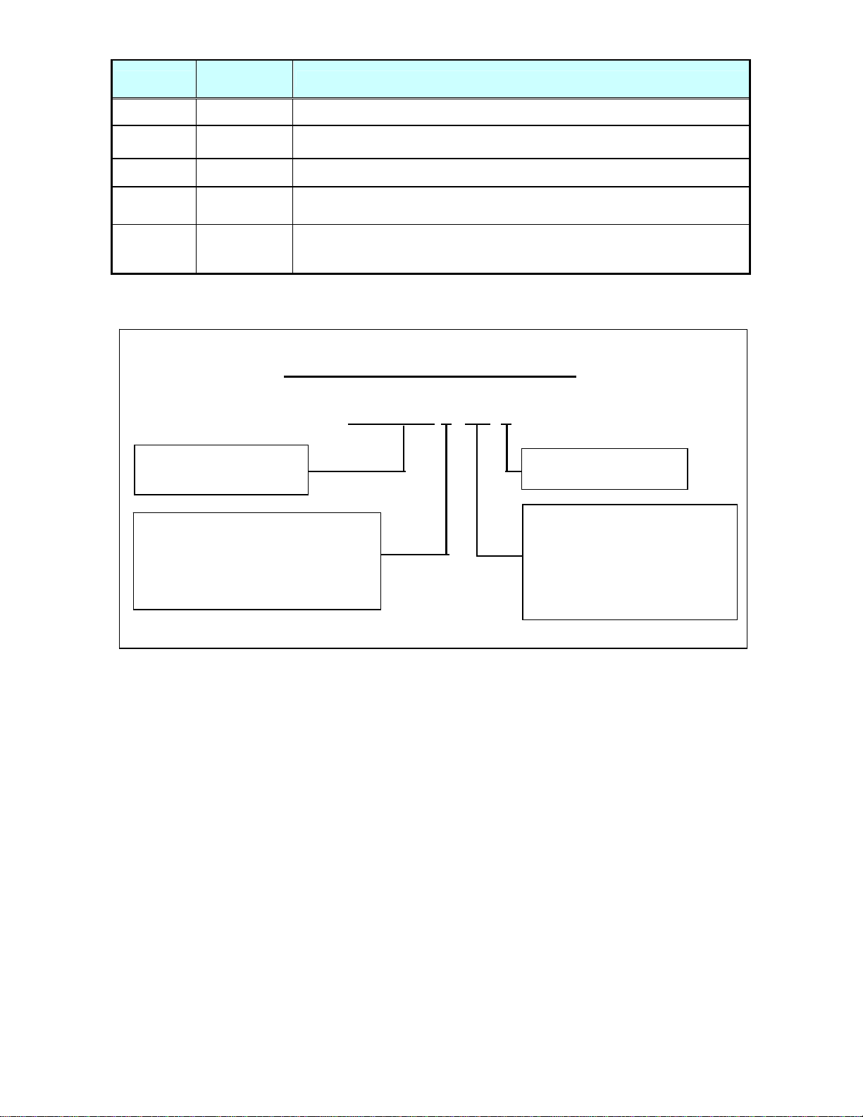
Manual Numbering Convention
DSP1500E-HM-4
Ver sion Nu mber
(Major Revision Level)
HS = SAN Unit Hardware
Operation Manual
HM = Multi / Main Unit Hardware
Operation Manual
HM-ENET = Ethernet Manual for
Multi / Main Unit
SW = Software Manual
iii
Page 4

Introduction
Thank you for purchasing our Electric Servo Press - DSP1500 System.
This instruction manual describes the procedures for installation, wiring, handling and
actions to be taken in case of any failure.
◆ This instruction manual shall be delivered to the end user who operates the equipment.
◆ Read all instructions before use and always keep this instruction manual with the
equipment.
◆ Items not described in this instruction manual shall be considered “unavailable”.
◆ The product specification and appearance described in this instruction manual is subject to
change without notice.
◆ All rights reserved. Any disclosure, copying, distribution, or use of the information
contained herein for other than its intended purpose, is strictly prohibited.
◆ It is important for you to read all “Safety Precautions” before using the equipment, and
understand and observe all instructions and recommendations included in this manual.
◆ Read all instructions and recommendations included in this manual, understand the
functions and performance of this servo press, and correctly use this machine.
◆ Wiring and para meter setting shall only be conducted by a qualified professional.
◆ Never conduct a withstand voltage test or insulation resistance test on this equipment.
◆ Indicate the following on all instruction manuals that use this equipment.
”This equipment is capable of high voltages hazardous to human life.”
Please confirm the following when unpacking this equipment:
◆ Ensure that you received the correct model as ordered.
◆ Ensure that there are no missing parts.
◆ Check for any damage caused during transportation.
For the safety of operator and equipment
Points to check when unpacking
iv
Page 5

Introduction
Warranty Period
The standard warranty period is one year from the date of purchase or one year from delivery to
the designated End User (not to exceed 18 Months). Actual terms are order specific.
Provision of warranty
If at any time during the warranty period your product proves to be defective, it will be repaired
free of charge as long as it was used properly in accordance with this instruction manual.
However, t he customer will be required to pay for repair charges in the following cases even if the
defects occurred within the warranty period.
1. Any defect due to improper conditions, improper circumstances and improper handling.
2. Any defect due to modifications or repairs performed by the customer.
3. Any defect caused by other equipment.
4. Any defect caused by customer failing to meet the equipment’ s speci fication.
5. Any defect due to natural disasters and accidents.
This warranty shall be limited to repairing or replacing this product. Any liability for indirect or
consequential loss or damage of any kind incurred or suffered by the customer due to a defect of
the product is excluded.
Warranty
v
Page 6
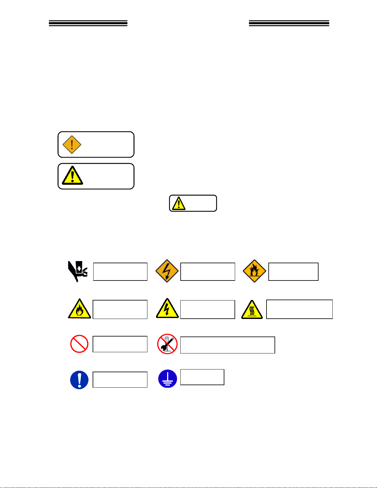
Safety Precau tion s
Read all instructions before operating the equipment in order to use this equipment safely and correctly.
Read this instruction manual carefully and fully understand the equipments functions, safety precautions
and instructions prior to using the equipment. Safety precautions in this manual are marked with two
symbols [Warning] and [Caution].
To prevent danger to the user and other persons as well as property damage, instructions that must be
fully observed are marked with the symbols below.
◆ This instruction manual uses the followi ng two sy mbols according to the deg ree o f damage that may
be caused when the instruction is not observed.
Even instructions that are marked with may result in severe damage if they are
not observed according to conditions.
Contents marked with the above symbols are very important instructions. For your safety, follow all
instructions and especially those marked with these symbols.
◆ This instruction manual uses the following additional symbols for instructions that shall be observed.
Warning
Caution
Warning:
Pinch Point
Caution:
Fire
Prohibited
Required
This symbol indicates that failure to observe instruction marked
with this symbol may result in severe personal injury or death.
This symbol indicates that failure to observe instruction marked
with this symbol may result in minor personal injury or material
damage.
Caution
Warning:
Electric shock
Caution:
Electric shock
Warning:
Fire
Caution:
High Temperature
Do not disassemble
Ground
vi
Page 7
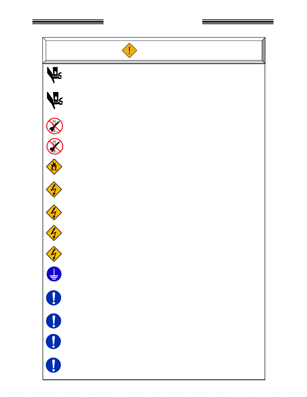
Safety Precautions
Never touch press ram during operation.
Failure to do so may cause injury.
Make sure t hat no part of you r body gets near any moving par t of the tool e ven while the
equipment is at r est. The press ram m ay lower for som e r eason resulting in injury.
When performin g maintenance or inspectio n, be sure to secure the press ram with safety
blocks to prohibit the ram from lowering.
Do not remove the motor and gear case of tool.
The press ram may lower resulting in injury.
Do not repair, disassemble , or modify the equipment individual components of the system.
Failure to obser v e this instruction may cause injur y, electric shock , f ir e, and malfunction.
Never operat e the equipm ent where it i s exposed to water, near a corros ive atmospher e or
flammable gases. Failure to observe this instruction may cause fire.
Keep fingers away from the connectors while the equipment is turned ON and for a while
after the equipment is turned OFF. Failure to observe this instruction may cause electric
shock.
Wiring operation and maintenance work shall be conducted by a qualified professional.
Failure to obser v e this instruction may cause electric s hock and injury.
Turn OFF the power when conducting wiring operation and maintenance. Failure to observe
this instruction may cau se ele ctr i c sho ck and injur y.
Never damage the cables, apply excess stress to cables, or squeeze the cables. Never use
damaged cables. Failure to observe this instruction may cause electric shock and fire.
Conduct type-3 grounding of FG terminals.
Failure to observ e this instruction may cause electric s hock.
In case of an abnormal odor, noise, or operation error occurrence, stop operation
immediately and turn OFF the power source. Failure to observe this instruction may cause
injury and fire.
Install a Power shutdown device in order to ensure the safety of equipment.
Failure to observ e this instruction may cause injury.
Install an emergency stop circuit on the outside of equipment in order to stop operation
promptly. Failure to observe this instruction m ay cause injury.
Keep away from the equipment during recovery from a temporary blackout, and ensure
safety measur es are condu c ted after restarting the equipment. The equip m ent may suddenly
restart. Failure to observe this instruction may cause injury.
Warning
vii
Page 8
Safety Precautions
Transportation / Storage
Transport the equipme nt properly according to its weight.
Failure to obser v e this instruction may cause injury and malfunction.
The conditions when transporting the equipment by ship is as below.
◆Ambient temperature: -5°C~+55°C (Avoid freezing)
◆Ambient humidity: 50% RH or lower (Avoid moisture)
◆Package: Tight seal
◆Rust prevention measure: Apply grease or oil on tools.
Failure to obser v e this instruction may cause earth lea kage and malfunct ion.
Do not hold cables or press ram when transport ing the tools.
Failure to obser v e this instruction may cause injury and malfunction.
Do not hold the indictor on the front panel when transporting the SAN Unit.
The indicato r may come off and d rop from the front panel.
Failure to obser v e this instruction may cause injury and malfunction.
The equipment shall be stored under the following conditions.
◆Ambient temperature: -5°C~+55°C (Avoid freezing)
◆Ambient humidity: 90% RH or lower (Avoid moisture )
◆Atmosphere: Indoors (Avoid direct sunlight)
No
No oil m ist, dust, water, salt, iron powder
◆Avoid direct vibration or shocks
Failure to obser v e this instruction may cause earth lea kage and malfunct ion.
corrosive gases or flammable gases
Caution
viii
Page 9
Safety Precau tion s
g
Installation / Wirin
Install the tools in a place that can support the weight and maximum load during operation.
Failure to observe this instruction may cause injury and malfunction.
Install the MAIN and/or SAN Units fir m ly inside the con trol panel using the s pecified screws.
Failure to observe this instr uction may cause m alfunction.
Use the specified tool for the SAN Unit.
Failure to observe this instr uction may cause fire and malfunction.
The MAIN and/or SAN Units shall ma intain the specified distance from other devices.
Failure to observe this instr uction may cause fire and malfunction.
Do not block the ventilation hole of the MAIN and/or SAN Units.
Avoid any foreign body from entering inside the equipment.
Failure to observe this instr uction may cause fire and malfunction.
The power source shall be provided with safety measures such as breakers and circuit
protectors. Failure to observe this instruction may cause fire and malfunction.
Do not use too ls or MAIN and/o r SAN Units that are damaged or have missing parts.
Failure to observe this instr uction may cause fire, injury, and malfunction.
Do not climb on top of the equipm ent or place he avy objects on the top of equipment.
Failure to observe this instruction may cause injury, and malfunction.
Do not subject the equipment to excess shock and impact.
Failure to observe this instr uction may cause m alfunction.
Conduct wiring properly and firmly.
Failure to observe this instr uction may cause injury, false operation, and malfunction.
Operate the equipment within the specified po wer supply voltage.
Failure to observe this instruction may cause injury, electric shock, fire, and malfunction.
When operat ing the equ ipment in the follow ing condit ion s, tak e sufficien t mea sures t o shie ld
the equipment .
◆Locations where electrical nois e is generated.
◆Locations where the equipment is subjected to a strong electric field or magnetic field.
◆Locations near high power wiring.
Failure to observe this instr uction may cause injury, false operation, an d malfunction.
Caution
ix
Page 10
Safety Precautions
Operation / Adjustment
Never operate the equipme nt with wet hand s.
Failure to observe this instruction may cause e l ectric shock.
Keep fingers aw ay from the SAN U nit radiating f ins and tool motor while the equipment is
turned ON or for a while after the equipment is turned OFF. These parts may become very
hot. Failure t o observe this instr uction may cause bur ns.
Use the equipment under the following conditions.
◆Ambient temperature: 0°C~+45°C (Avoid freezing)
◆Ambient humidity: 90% RH or lower (Avoid moisture)
◆Atmosphere: Indoors (Avoid direct sunlight)
No
No oil mist, dust, water, salt, iron powder
◆Avoid direct vibration or shocks
Failure to observe this inst r uction may cause earth leak age and malfunction.
Confirm and adjust all parameters before operation in order to prevent unexpected
movement of t he equipmen t.
Failure to observe this in str uction may ca use injury, false operation and malfunction.
Never conduct extreme adjustments or setting changes that may cause instability of
operation.
Failure to observe this in str uction may ca use injury, false operation and malfunction.
The equipment may restart suddenly when the equipm ent is reset with the start signal ON.
Always ensure that the start signal is O FF before resettin g the equipment.
Failure to observe this in st r uction may ca use injury.
Do not turn ON and OFF the equipment repeatedly.
Failure to observe this instr uction may cause m alfunction.
Do not use the equipment at l oads higher than the maximum lo ad.
Failure to observe this instruction may shorten equipment life or cause malfunction due to the
high temperature caused by overload.
The magnetic brake is for holding the press ram when performing maintenance procedures.
Do not use for normal braking otherwise failure m ay result.
The magnetic brake may fail to hold near the end of its life expectancy due to wear.
Secondary braking structures should be installed on the machine side to safely secure
otherwise injury may result.
In case any abnormality occurs, remove the cause and ensure safety before resetting and
restarting the equipment.
Failure to observe this inst r uction may cause injury.
corrosive gases or flammable gases
Caution
x
Page 11

Table of Contents
Chapter 1: Outline
1.1 About this Manual......................................................................................... 1-2
1.2 Functions...............................…..……………………………………………… 1-3
1.3 Safety Precautions……….....…..………………………………………………. 1-4
Chapter 2: Specifications
2.1 Specifications.........................………………………………………………….. 2-2
2.2 Unit Dimensions……….................................…….…………………………… 2-3
Chapter 3: System Description
3.1 System Block Diagram...........………………………………………………….. 3-2
3.2 Unit Description…….....................................…….…………………………… 3-3
Chapter 4: Installation & Wiring
4.1 Unit Dimensions.....................………………………………………………….. 4-2
4.2 Installation…….............................................…….…………………………… 4-3
4.3 Power Wiring Reference........………………………………………………….. 4-4
4.4 Input Power Connection........………………………………………………….. 4-5
4.5 RS485 Connection…….........………………………………………………….. 4-5
4.6 Serial Communication Ports..………………………………………………….. 4-6
4.6.1 PC Port………............................………………………………………….. 4-7
4.6.2 Display Port…............................………………………………………….. 4-7
4.6.3 Data-Out (1) Port........................………………………………………….. 4-7
4.6.3.1 Available Output Data...........………………………………………….. 4-8
4.6.3.2 Output Data Format..............………………………………………….. 4-9
4.6.4 Data-Out (2) Port........................………………………………………….. 4-10
4.6.5 Data-In Port…............................………………………………………….. 4-10
4.6.6 Serial Communication Cables….………………………………………….. 4-11
4.7 User Console Ethernet Connection..…… ……… …………………………….. 4-12
4.8 PLC Interface Communication (I/O).………………………………………….. 4-13
4.8.1 External I/O Disable Switch…....………………………………………….. 4-14
4.9 Firmware Flash Connector………….………………………………………….. 4-14
Chapter 5: Control Interfaces
5.1 Interface Board Setup……….………………………………………………….. 5-2
5.2 Signal Timing Chart…..................................…….…………………………… 5-3
5.2.1 Sequence Operation..................………………………………………….. 5-3
5.2.2 Jog (Manual) Operation.............………………………………………….. 5-4
xi
Page 12

Table of Contents
5.3 Discrete I/O Interface….........………………………………………………….. 5-5
5.3.1 Sinking Type (NPN)…................………………………………………….. 5-5
5.3.1.1 Discrete Signal Connection (Sinking Type)………………………….. 5-6
5.3.2 Sourcing Type (PNP)..................………………………………………….. 5-7
5.3.2.1 Discrete Signal Connection (Sourcing Type).……………………….. 5-8
5.3.3 Input Signals (PLC-IN)................………………………………… ……….. 5-9
5.3.4 Output Signals (PLC-OUT).........………………………………………….. 5-11
5.3.4.1 Output Data Banks.…...........………………………………………….. 5-15
5.4 Interbus S
5.4.1 Component Descriptions............………………………………………….. 5-18
5.4.2 User Console Software Settings ………………………………………….. 5-19
5.4.3 Input Signals (Reference Layout)..……………………………………….. 5-20
5.4.4 Output Signals (Reference Layout)……………………………………….. 5-22
5.5 DeviceNet
5.5.1 Component Descriptions...........………………………………………….. 5-25
5.5.2 User Console Software Settings ………………………………………….. 5-26
5.5.3 Input Signals (Reference Layout)..……………………………………….. 5-27
5.5.4 Output Signals (Reference Layout)……………………………………….. 5-29
5.6 Profibus
5.6.1 Component Descriptions............………………………………………….. 5-32
5.6.2 User Console Software Settings ………………………………………….. 5-33
5.6.3 Input Signals (Reference Layout)..……………………………………….. 5-34
5.6.4 Output Signals (Reference Layout)……………………………………….. 5-36
5.7 Modbus Plus
5.7.1 Component Descriptions............………………………………………….. 5-39
5.7.2 User Console Software Settings ………………………………………….. 5-41
5.7.3 Input Signals (Reference Layout)..……………………………………….. 5-42
5.7.4 Output Signals (Reference Layout)……………………………………….. 5-44
5.8 CC-Link
5.8.1 Component Descriptions........... ………………………………………….. 5-47
5.8.3 Input Signals (Reference Layout)..……………………………………….. 5-49
5.8.4 Output Signals (Reference Layout)……………………………………….. 5-51
5.9 CC-Link
5.9.1 Component Descriptions............………………………………………….. 5-54
5.9.2 User Console Software Settings ………………………………………….. 5-56
5.9.3 Input Signals (Reference Layout)..……………………………………….. 5-57
5.9.4 Output Signals (Reference Layout)……………………………………….. 5-59
5.10 Allen-Bradley Remote I/O Interface………………………………………….. 5-60
5.10.1 Component Descriptions...........………………………………………….. 5-62
5.10.2 User Console Software Settings .……………………………………….. 5-63
5.10.3 Input Signals (Reference Layout).……………………………………….. 5-64
5.10.4 Output Signals (Reference Layout).…………………………………….. 5-66
Interface..…........………………………………………………….. 5-16
®
Interface.…........………………………………………………….. 5-23
®
Interface.……...... ..………………………………………………….. 5-30
®
Interface.........………………………………………………….. 5-37
®
Interface (Version 1)..……………………………………………….. 5-45
®
Interface (Version 2)..……………………………………………….. 5-52
®
xii
Page 13

Table of Contents
5.11 Ethernet-I/P Interface…........………………………………………………….. 5-67
5.11.1 Component Descriptions...........………………………………………….. 5-68
5.11.2 User Console Software Settings. .……………………………………….. 5-69
5.11. 3 Input Signals (Reference Layout).……………………………………….. 5-70
5.11.4 Output Signals (Reference Layout)..…………………………………….. 5-72
5.11.5 PLC Message Transfer Setup Example…..…………………………….. 5-73
Chapter 6: Troubleshooting
6.1 Abnormals…………………….………………………………………………….. 6-2
xiii
Page 14

Blank Page
xiv
Page 15

Chapter 1: Outline
Page 16
Chapter 1: Outline
enFORCE DSP1500 Main Unit Hardware Manual
1.1 About this Main Unit Manual
This manual details the configuration, specifications and the operation of the DSP1500 Main Unit.
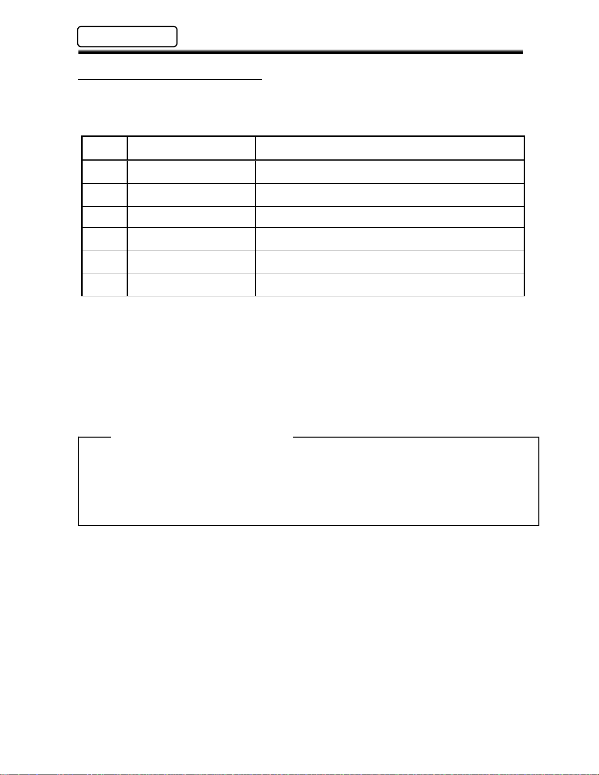
The following table outlines the contents of each chapter.
Chapter
1 Outline
Title Contents
Basic characteristics and requirements of the DSP1500
Main Unit.
2 Specifications General specifications of the DSP1500 Main Unit.
3 System Description Description of standard and optional system components.
4 Installation and Wiring
5 Control Interfaces
Mounting requirements, wiring connection references
including communication port specifications.
Description of standard Discrete I/O and optional Fieldbus I/O
PLC Interfaces.
6 Troubleshooting Description of Abnormal conditions.
Any questions regarding the contents of this document or any related matter should be
directed to FEC Inc. at (586) 781-2100 or faxed to (586) 781-0044.
The Information set forth in the following document is the property of FEC Inc. This
document shall not be released to or copied for any person and/or organization without
the expressed prior consent of FEC Inc.
Unauthorized reproduction or distribution of this manual is strictly prohibited. Please
contact FEC Inc. if additional copies are required.
Related Docum entation
DSP User Console Manual DSP1500E-SW-*
DSP1500 SAN Unit Operation Manual DSP1500E-HS-*
(Rev. 4.0) PAGE 1 - 2
Page 17

enFORCE DSP1500 Main Unit Hardware Manual
Chapter 1: Outline
1.2 Functions
The Main Unit is a complimentary controller device to enhance the DSP1500 capabilities by
providing the communication and the sequence control features required by larger or more
sophisticated multi press applications. When a group of DSP1500 Servo Controllers (SAN Units) are
linked to a Main Unit, the Main Unit assumes control (over these presses) of the following functions:
Input-Output (I/O) Connection (including Fieldbus interface)
Sequence Control
Parameter Programming
Pressing Data Monitoring & Communication
General Status Indication
♦ Input-Output Connection (including Fieldbus interface)
The Main Unit assumes control of the control signals (Ex.: STOP, START, RETURN,
BYPASS, etc.) to all of the DSP1500 Servo Controllers linked to it via the RS485
communication port, thus eliminating direct connection & control to the individual presses.
The control signals for the multi-press array can be of different sources: Signals manually
generated by pressing the Control Buttons on the front of the Main Unit or I/O (Input/Output)
signals from a PLC or from a PC Based Controller.
♦ Sequence Control
The Main Unit controls the pressing sequencing eliminating the need for external control
devices (PLC) to perform complicated control sequencing. All pressing sequencing is
handled by the Main Unit. This built in feature allows the Main Unit to control a variety of
complex sequencing strategies including; several pressing steps, reject (retry) strategies,
wait timing, multiple starts, etc.
♦ Parameter Programming
A Windows® compatible computer running the DSP User Console software package can be
connected to the Main Unit in order to upload or download the preset data to all the SAN
(Servo) Controllers connected in the multi press array. This eliminates the need to program
individual presses manually.
♦ Pressing Data Monitoring & Communication
The Main Unit can monitor and process the pressing results collected by the DSP1500 Servo
(SAN) Controllers connected to it. It has four (4) configurable RS232C ports to input and
output pressing data results. Data monitoring / saving is also a function of the DSP User
Console software package.
As an added feature, the Main Unit stores previous pressing data in RAM (volatile) for
uploading at another time. The number of cycles stored is based on the number of presses
connected (see chart on page 2-2). The data can be uploaded using the DSP User Console
software package.
♦ General Stat us Indi ca tio n
A set of indicator LED’s provide the status for Power On, Busy, Total Accept, Total Reject and
Abnormal conditions.
PAGE 1 - 3 (Rev. 4.0)
Page 18

Chapter 1: Outline
enFORCE DSP1500 Main Unit Hardware Manual
1.3 Safety Precautions
To ensure the most effective and extended use of all equipment, adhere to the following
precautions:
¾ Wiring
¾ Installation Environment
¾ Static Electricity
¾ Cleaning
¾ Electrical Noise Prevention
¾ Handling and Shipping
(Rev. 4.0) PAGE 1 - 4
• Use only the specified cables for all system connections.
• Do not use a high voltage circuit as a frame ground (FG). Also, the frame ground should be
separate from the power ground. The use of a grounding rod located as close as possible to
the enclosure housing the DSP1500 Main Unit is preferable.
• Circuit breakers or fuses are required on branch circuit power feeds to the Main Unit.
• PLC I/O cables must be run separate from any high voltage sources or cabling, and must not
exceed 50 feet.
• The DSP1500 Main Unit should be placed in a NEMA 12 enclosure.
• Using the equipment in the following locations may lead to malfunction or breakdown. Avoid
using in these areas or use an air conditioner.
Areas under direct sunlight or if the environmental temperature is out of the 32~122℉
(0~50℃) range.
Areas where relative humidity is out of the 20-90% range, the temperature change is
drastic or where the area is exposed to mist and water drops.
• Do not use at the following locations. (Contact FEC Inc. if necessary for clarification)
Areas where conductive powder, oil, mist, salt or organic solvents exist.
Areas that have corrosive or combustible gases.
Areas that have strong electric or magnetic fields.
Areas where strong vibration or shock could be transmitted directly to a Main Unit.
• The DSP1500 Main Unit incorporates many electronic Surface Mounted Devices (SMD). It is
advisable to strictly adhere to practices for safe electrostatic discharge in order to prevent
damage to the system components when handli ng them.
• Do not use any organic solvents, such as thinner, to clean a Main Unit. The solvent could
melt the surface paint, or penetrate inside and cause damage. A cloth dampened with
alcohol or warm water should be used to lightly wipe the components.
• Main Units must be located a minimum of 600mm from high transient voltage sources such
as transformers, motor starters, AC inverters and AC contactors. If it cannot be avoided, the
unit must be shielded.
• If high powered devices are used inside the enclosure, they must use a surge suppression
device.
• Make sure that the power supply lines and cables for connecting the unit and tool are not run
together inside the same duct.
• It is cr itical that DSP1500 System components are properly handled and shipped in order to
maintain the system’s integrity. Adhere to the following requirements for shipping and
handling:
Loose DSP1500 Main Units must be individually packaged and shipped in anti-static
containers or wrap to prevent damage from electrost ati c discharge.
If the Main Unit is to be shipped in an enclosure, tighten all mounting screws to
prevent the unit from being dislodged.
Do not ship or store the unit in environments where the temperature is out of the
23~131℉ (-5~55℃) range or where the humidity is above 90%.
Page 19

Chapter 2: Specifications
Page 20
(
)
(
)
Chapter 2: Specifications
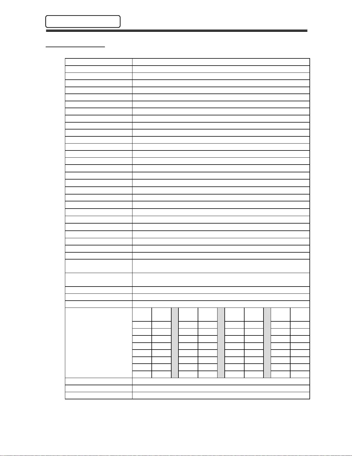
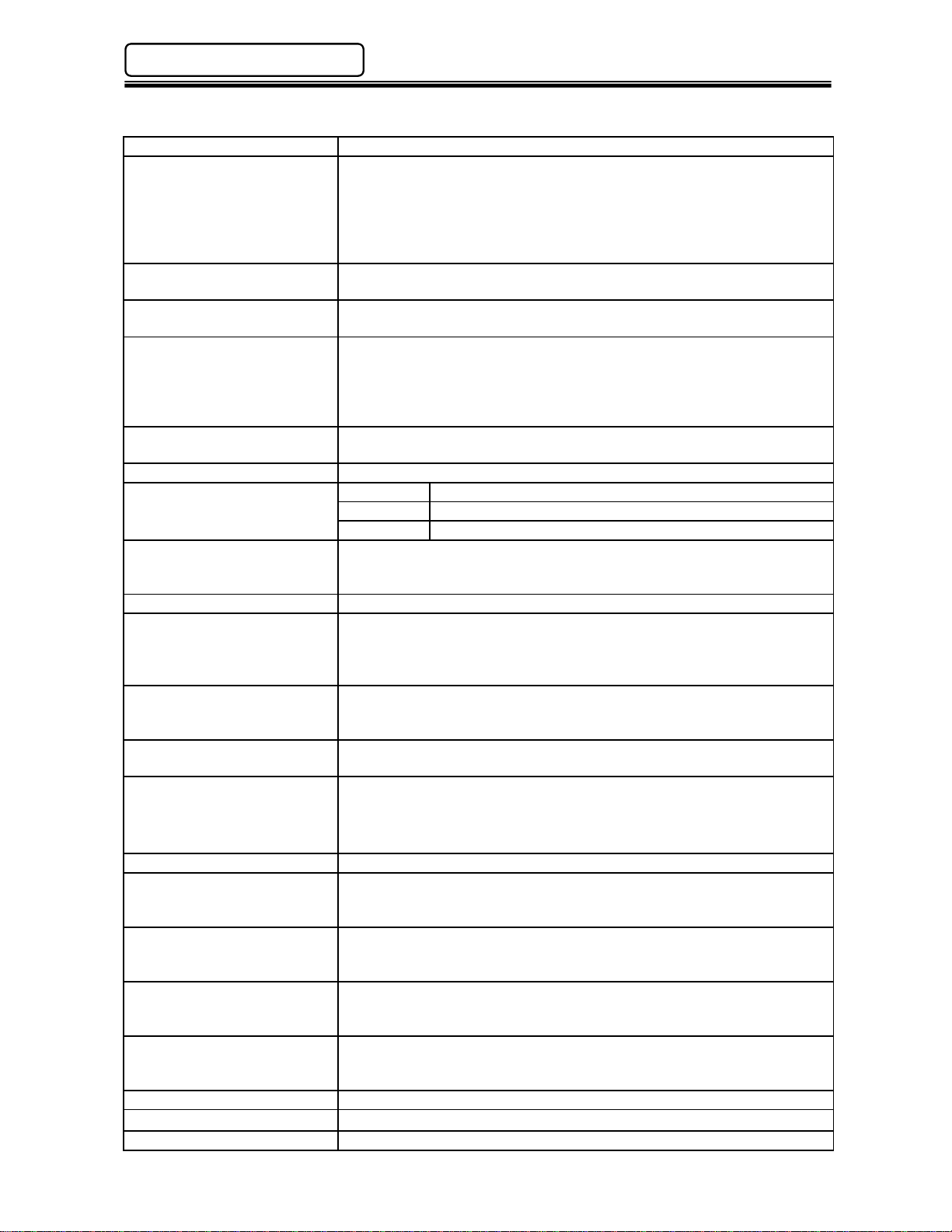
2.1 Specifications
Power Supply Voltage 100 to 220 VAC±15%, 1-phase, 50/60 Hz.
Power Consumption 9 Watt/Hour
Operating Current Less than 70 mA
In rush current Less than 160 mA
CPU NEC V53A
Data Communication RS 232C (User Console PC)
RS232C
RS232C (Data Input)
RS232C (Data Output #2)
RS422 (External Remote Display)
RS485 Servo Units Programming/Control
Ethernet - User Console (User Console PC)
Ethernet - Network Communication (2E Version Only)
Control Interfaces Discrete I/O (24Vdc Sink)
Discrete I/O (24Vdc Source)
Allen Bradley Remote I/O 1
Ethernet I/P (includes messaging capabilities)
M-Net
Pressing Sequence
Programming Steps
Pressing
Control Methods
Max. No. of presses 31 per Main Unit
Pressing Parameters 32
Pressing Sequences 32
Data Storage
(non-volatile RAM)
Based on the number of
presses connected.
Installation requirement NEMA12 Enclosure
Operation Temperature 0º to 50 ºC (32 º to 122 ºF)
Operation Humidity 20% to 90%
1) Mitsubishi CC Link & Allen Bradley Remote I/O are proprietary and licensed for use.
2) The number of cycles stored will be reduced if RS232C - DATA IN data is stored with the
pressing data.
enFORCE DSP1500 Main Unit Hardware Manual
Data Output #1
DeviceNet
Interbus-S
Profibus
Mitsubishi CC Link
Modbus Plus
CC Link
DeviceNet
Interbus-S
Profibus
Also Available: Contact FEC for special fieldbus requirements.
100
(99 plus End Step)
Load Control / Distance Control
plus 7 other special methods
Stored
# of
Press
Cycles
1 8322 9 2475 17 1434 25 1012
2 6526 10 2250 18 1350 26 984
3 5289 11 2081 19 1294 27 928
4 4445 12 1941 20 1237 28 900
2
5 3826 13 1828 21 1181 29 872
6 3375 14 1716 22 1125 30 843
7 3010 15 1603 23 1097 31 815
8 2700 16 1519 24 1040
(includes messaging capabilities)
®
®
®
1
®
®
Version 2 (includes messaging capabilities)
®
for ToolsNet®
®
for ToolsN e t®
®
for ToolsNet®
®
# of
Press
Stored
Cycles
# of
Press
Stored
Cycles
# of
Press
Stored
Cycles
(Rev. 4.0) PAGE 2 - 2
Page 21
enFORCE DSP1500 Main Unit Hardware Manual
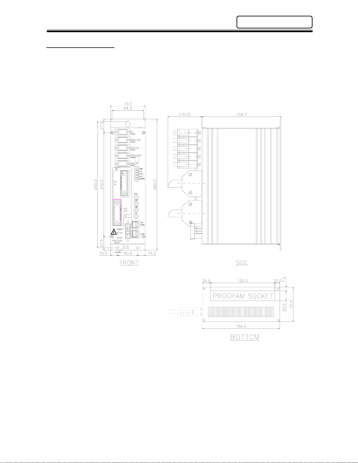
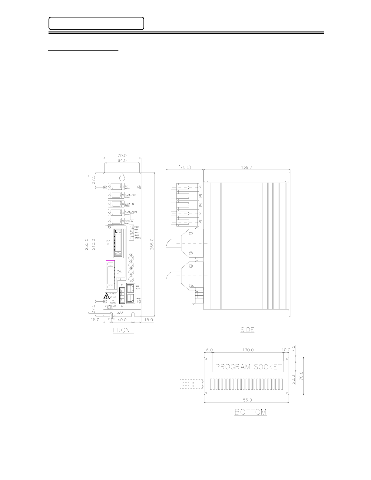
2.2 Unit Dimensions
Weight: 1.4 kg
Chapter 2: Specifications
PAGE 2 - 3 (Rev. 4.0)
Page 22

Chapter 2: Specifications
enFORCE DSP1500 Main Unit Hardware Manual
Blank Page
(Rev. 4.0) PAGE 2 - 4
Page 23

Chapter 3: System Description
Page 24
Chapter 3: System Description
enFORCE DSP1500 Main Unit Hardware Manual
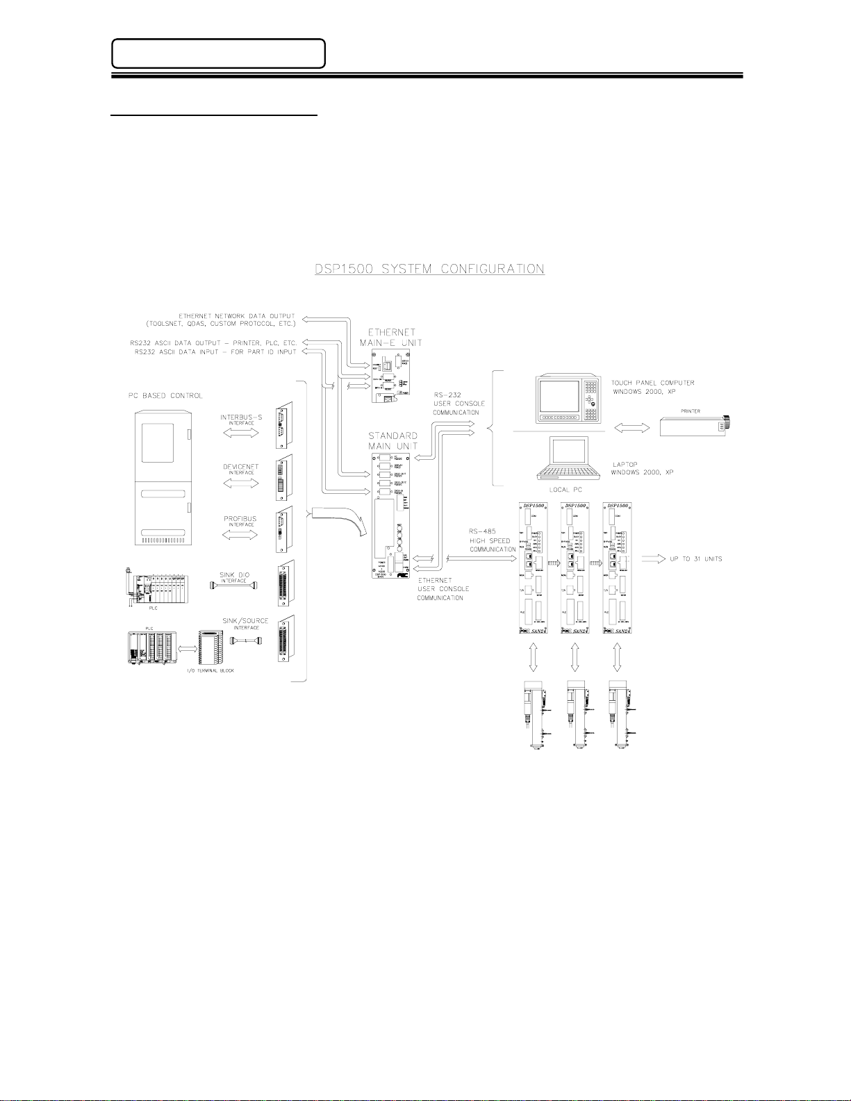
3.1 System Block Diagram
The diagram below shows how the DSP1500 Main Unit can be connected to a single unit or combined
in a multiple press configuration. The use of a Main Unit provides one set of PLC I/O for c ontrolling
multiple pressing operations. Along with discrete 24VDC (sinking or sourcing) I/O, various fieldbus
interf ac es are al s o a va i la bl e for dire c t connecti o n t o n e t wo r ks such as Profi bus, AB remote I/O , C CLink,
DeviceNet, etc.
The DSP1500 Main Unit also provides an interface for connection to the User Console PC, serial
printers, barcode readers, display units, etc.
(Rev. 4.0) PAGE 3 - 2
Page 25
enFORCE DSP1500 Main Unit Hardware Manual
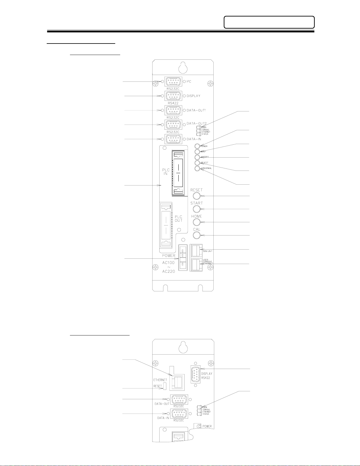
3.2 Unit Description
Chapter 3: System Descriptio n
Standard Version
(RS232C) Data-Out Port #1
(RS232C) Data-Out Port #2
(RS232C) PC Port
(RS422) Display Port
(RS232C) Data-In Port
* Discrete I/O Interface Board Shown.
Interface Board
Power Connector
Ethernet U/C
Status LED
Power ON LED
Busy LED
Accept LED
Reject LED
Abnormal LED
Reset Button
Start Button
Home Button
Calibration Button
RS485 Port
Ethernet U/C Port
Ethernet (E) Version
Ethernet Network Port
Ethernet Reset Button
(RS232C) Data-Out Port
(RS232C) Data-In Port
(RS422) Display Port
Ethernet U/C
Status LED
PAGE 3 - 3 (Rev. 4.0)
Page 26
Chapter 3: System Description
®
enFORCE DSP1500 Main Unit Hardware Manual
Main Unit Panel Description
Power On LED Indicates when power is applied to the Main Unit.
Busy LED Lights when the unit is performing a self check, Home Search, Home
Return, Sequence operation, Jog operation or is
downloading/uploading data to the DSP Software.
Blinks when clearing stored data in the Main Unit and while
communicating when “Disable Main Unit When Communicating” is
checked in the DSP Software.
Accept LED Lights if a pressing cycle or a self check test falls within acceptable
parameters. (This LED indicates status for ALL connected presses)
Reject LED Lights if a pressing cycle or a self check test is outside of acceptable
parameters. (This LED indicates status for ALL connected presses)
Abnormal LED Lights when a system abnormal condition is detected in the control
system of any connected press. (Does NOT indicate a press reject).
All operations are halted and cannot be restarted until the Abnormal
condition is corrected. Can be cleared only by the Reset function. (see
DSP1500 SAN Unit Operation Manual for Abnormal Troubleshooting)
RS485 Port RJ45 style connector used to connect to all DSP1500 Servo (SAN)
Units included in the system.
Ethernet U/C Port Communication port for the User Console PC.
Red (TX) Transmitting Data
Ethernet U/C Status LEDs
Reset Button Resets all signal and communication buffers to “clear” conditions.
Start Button Starts the pressingcycle. Must be maintained during complete cycle.
Home Button If any of the connected presses have not been “Homed”, pushing this
Cal Button Performs the Load Transducer shunt calibration test. When pressed,
Power Connector Connects to incoming power: 100 to 220VAC (auto-sensing), Single
Interface Board (I/O) Allocation socket for input/output signal Interface boards. Options
RS232C – PC Port Communication port for the User Console PC.
RS232C – Data Out Port #1 Communication port for pressing result data output to a serial printer.
RS232C – Data Out Port
(Ethernet Version)
RS232C – Data In Port Co mmuni cation port for ASCII data input fro m periphe ral devices. (Ex:
RS232C – Data Out Port #2 Communication port for pressing result data output to a host
RS422 – Display Port Communication Port for an FEC Remote Display Unit
Ethernet Network Port*
Ethernet Reset Button* for resetting the Network Ethernet Port
*On Ethernet Version only.
Yellow 10/100 Link
Green (RX) Receiving Data
Clears the Abnormal signal and performs the Load Transducer Zero
Level Check.
button will cause those presses to perform a “Home Position Search”.
If Home has been set, the connected presses will move to the Home
Position.
the Servo (SAN) Units will display either a green accept LED or red
reject LED indicating status of the individual Calibration test.
phase, 50/60 Hz.
available are Discrete I/O (Sink or Source), Interbus-S
Profibus
, CC-Link® (Version 1 or 2), Modbus Plus®, Allen Bradley
®
, DeviceNe t®,
®
Remote I/O (Rockwell License #199906006) or Ethernet-I/P
Data output format is configured using the User Console (DSP)
Software package.
Communication port for pressing result data output to any external
device, i.e.: host computer, serial printer, etc. Data output format is
configured using the User Console (DSP) Software package.
bar code readers, RF tag, etc.) Allows external ASCII data to be
merged with pressing result data.
computer. Data output format is configured using the User Console
(DSP) Software package.
for Network Connectivity (Toolsnet
, QDAS®,Custom Protocol, etc.)
(Rev. 4.0) PAGE 3 - 4
Page 27

Chapter 4: Installation & Wiring
Page 28
Chapter 4: Installation & Wiring
enFORCE DSP1500 Main Unit Hardware Manual
4.1 Unit Dimensions
Main Units must be mounted with a minimum clearance of 13mm on each side to allow proper heat
dissipation. Cable connections on the front of the units require 100mm of clearance. Allow a
minimum of 100mm clearance on the bottom of the unit for flash connector hook up when updating
firmware.
Mounting: Top (1) place #8-32 screw
Bottom (2) places #8-32 screw
Weight: 1.4 kg
(Rev. 4.0) PAGE 4 - 2
Page 29
enFORCE DSP1500 Main Unit Hardware Manual
Chapter 4: Installation & Wiring
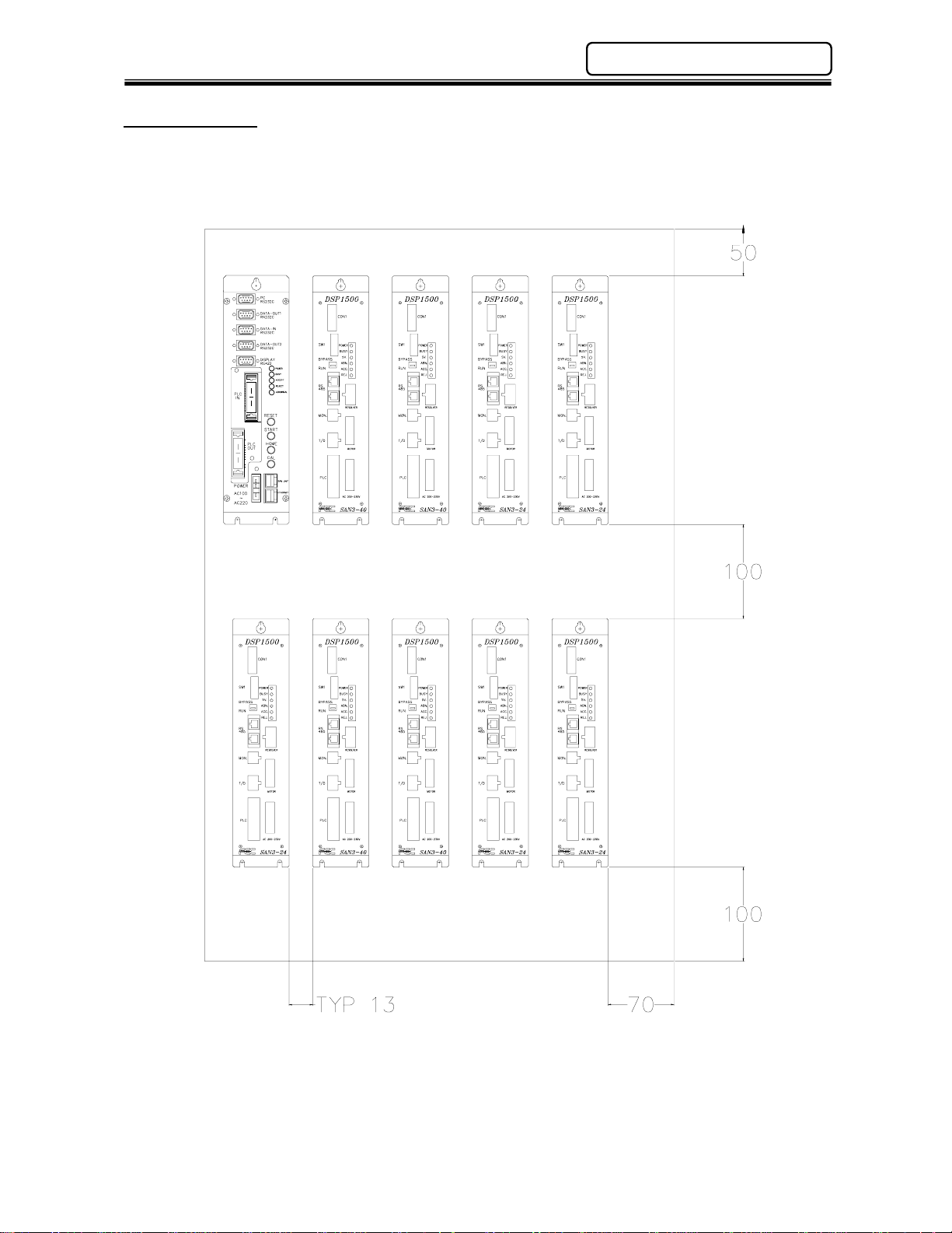
4.2 Installation
The Main Unit should be mounted into a NEMA12 / IP52 enclosure at a minimum and spaced similar
to the DSP1500 SAN Units (Shown Below).
PAGE 4 - 3 (Rev. 4.0)
Page 30
Chapter 4: Installation & Wiring
enFORCE DSP1500 Main Unit Hardware Manual
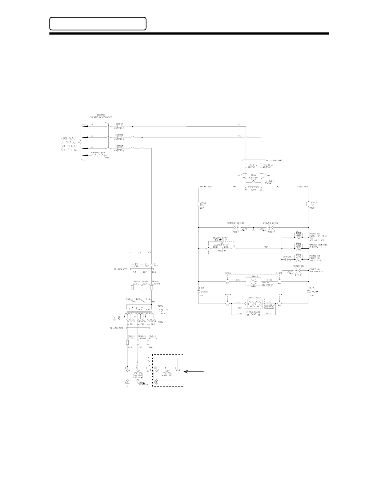
4.3 Power Wiring Reference
Even though the Main Unit power input allows it to connect to 120 VAC ~ 220 VAC power lines,
typically the unit is connected to the same power source that the SAN Units are connected to (200 to
220 VAC ± 10%) . In the example wiring diagram shown below there are two power branches; one is
for the control circuitry connected to 120 VAC and the other is for the SAN power circuitry connected
to 220 VAC. For convenience, the Main Unit is wired together with the DSP1500 Servo Controllers.
Note that the Main Unit is using one phase while the Servo Controllers use three phases.
Main Unit Power Reference
Note: Diagram shown with the Main Unit wired using same cable used for SAN Unit for
standardizing components. Pin #2 is not wired internally on the Main Unit.
(Rev. 4.0) PAGE 4 - 4
Page 31

enFORCE DSP1500 Main Unit Hardware Manual
Chapter 4: Installation & Wiring
4.4 Input Power Connection
An auto sensing power supply allows for input power in the range of 100 ~ 220VAC single phase,
50/60 hertz. Adequate circuit protection must be provided. Recommended conductor size should be
a minimum of #16AWG.
Wiring Chart
4: 100 ~ 220VAC +/-15%
3: 100 ~ 220VAC +/-15%
2: No Connection **
1: Frame Ground
4
3
2
1
Manufacture: Amp
Housing Part No.: 1-178128-4
Mating Conn ec tor
Contact Part No.: 1-175218-3 (Qty.-3)
** To standardize components, FEC cable
part #FEB-1280 may be used due to the fact
that pin #2 is not connected internally .
4.5 RS485 Connection
The Main Unit uses an RS485 port to perform the communication operations with the DSP1500
Servo (SAN) Controllers. This port has two channels CH1 and CH2. CH1 is dedicated to handle all
preset data upload and download, pressing results monitoring and collection. Channel CH2 is a high
speed connection to all DSP1500 Servo Controllers. It controls all required commands to perform
the pressing cycle.
RS485 port specifications (RJ45)
Speed 9600, 19200, 38400 baud
Cable Std Cat 5 Ethernet
Maximum number of
connected devices
Protocol Proprietary
Operating Voltage RS485 Standard
RS485 Wiring
8
Pin Signal Name Channel
1 TX+ / RX+ CH1
2 TX- / RX- CH1
3 RX+ CH2
4 TX- CH2
5 TX+ CH2
6 RX- CH2
7 GND
8 GND
31
PAGE 4 - 5 (Rev. 4.0)
Page 32

Chapter 4: Installation & Wiring
enFORCE DSP1500 Main Unit Hardware Manual
4.6 Serial Communication Ports
The Main Unit has four usable serial RS232C (two on Ethernet Versions) and one RS422
communication port. All of these ports settings and data format are fully configurable with the DSP
User Console software.
(OPTIONAL)
STANDARD VERSION ETHERNET VERSION
RS-232C Signal Layout
1 DCD (Data Carrier Detect) Used only for DATA-IN*
2 RXD (Receive Data) Serial Data Input.
3 TXD (Transmit Data) Serial Data Output.
4 DTR (Data Terminal Ready) Output signal; active when the internal device is ready to link.
5 GND (Ground Signal)
6 DSR (Data Set Ready)
7 RTS (Request to Send)
8 CTS (Clear to Send)
9 RI (Ring Indicator) Not used
* When using th e DATA-IN port, PIN 1 (DCD) must be enabled for data input (Jumper pins 1 & 4)
Input signal; in dicates that the external device is r eady to establish a
link. Can be connected directly to DTR for automatic data dump.
Output signal. Active when the internal device is ready to exchange
data.
Input signal. Indicates that the external device is ready to exchange
data. Can be connected directl y to RTS when no as yn chronous data
flow is required.
(Rev. 4.0) PAGE 4 - 6
Page 33

enFORCE DSP1500 Main Unit Hardware Manual
Chapter 4: Installation & Wiring
4.6.1 PC Port
The “PC” port is for communicating with the DSP Software in the User Console PC. The
connecting cable is a standard RS232 Null-Modem cable and can be purchased through FEC
(Part #FEB-1301) or through any authorized RS232 cable supplier. T his port is not available on
Ethernet Version units.
RS-232 Pin Layout
1 DCD
2 RXD
3 TXD
4 DTR
5 GND
6 DSR
7 RTS
8 CTS
9 Not Used
4.6.2 DISPLAY Port
“DISPLAY” port is used to connect to an FEC Remote Display Unit.
RS-422 Pin Layout
1 TX+
2 TX-
3 RX+
4 RX-
5 GND
6 Not Used
7 Not Used
8 Not Used
9 Not Used
4.6.3 DATA-OUT (1) Port
“DATA -OU T(1)” is an output port for ASCII fastening data communication to external devices.
RS-232 Pin Layout
1 DCD
2 RXD
3 TXD
4 DTR
5 GND
6 DSR
7 RTS
8 CTS
9 Not Used
PAGE 4 - 7 (Rev. 4.0)
Page 34

Chapter 4: Installation & Wiring
4.6.3.1 Available Output Data
The Main Unit is capable of outputting the press results data in an ASCII format to a serial
printer or other peripheral devices. The data is sent from the Main Unit’s RS232C “DATA
OUTPUT” ports. The output data string as well as port configuration can be configured by the
DSP User Console Software. Control Characters may also be implemented (Ex: Start of Text,
End of Text, etc.). Below is a list of data available and its byte length.
Basic Pressing Data Length in bytes
Judgment Load
Final Load
Judgment Distance
Final Distance
Cycle Time
Judgment
Extended Pressing Data Length in bytes
Distance Measureme n t Star t Dista n ce 7
Interference Check Distance 8
Part Check 1 Distanc e 8
Part Check 2 Minim um Load 6
Part Check 2 Maximum Load 6
Part Check 2 Distance at Minimum Load 7
Part Check 2 Distance at Maximum Load 7
Part Check 2 Minim um Load 6
Part Check 2 Maximum Load 6
Part Check 2 Distance at Minimum Load 7
Part Check 2 Distance at Maximum Load 7
Absolute Distance 7
Input Data* Length in bytes
RS232C data buffer 1
RS232C data buffer 2
RS232C data buffer 3
RS232C data buffer 4
System Data Length in bytes
Date 10
Time 8
Press Number 2
Sequence Number 2
Parameter Number 2
Cycle Count 7
*Input Data is input to the Main Unit using the RS232C “DATA INPUT” port. This port is
configured through the DSP User Console Software. The data must be ASCII formatted data &
is limited to 128 bytes in (4) separate data buffers. The port must be configured for the input
string which is to be received. The data received can then be married with the resultant pressing
data by selecting the RS232 data in the output format. This function is typically used to marry a
part number with the resultant pressing data for production birth history.
enFORCE DSP1500 Main Unit Hardware Manual
6
5
8
7
5
3
Up to 128
This length is determined b y t he user and
dependent upon the length of data input to
these data areas.
(Rev. 4.0) PAGE 4 - 8
Page 35

enFORCE DSP1500 Main Unit Hardware Manual
4.6.3.2 Output Data Format
The example below shows the format of the DATA-OUT (1) port connected to a printer. Actual
data output format may vary depending on the configuration and set-up of this port using the
DSP User Console Software. The data field is selectable from all the available output fields to as
little as one output field (See previous table for available data fields). Headers, footers & ASCII
control characters are all configurable using the DSP User Console Software.
2007/09/26 09 :17:57 SEQ01 [Input Data f r om DATA-IN]
SP PA F LD F DS JUG Acceptable Pressing
01 01 1.50 126.042 O
2007/09/26 09 :19:36 SEQ01
SP PA F LD F DS JUG Rejected Pressing
01 01 1.08L 130.001H X
2007/09/26 09 :21:16 SEQ01
SP PA F LD F DS JUG Cycle Stopped
01 01 0.38L 93.540L ! (Before pressing end)
2007/09/26 09 :21:34 SEQ01
SP PA F LD F DS JUG Abnormal
01 01 0.01L 0.001L A05 (Showing abnormal code)
2007/09/26 09 :21:21 SEQ01
SP PA F LD F DS JUG Press Bypassed
01 00 0. 0.
Index
SEQ: Sequence F LD: Final Load H: High
SP: Press Number F DS: Final Distance L: Low
PA: Parameter JUG: Judgment
Chapter 4: Installation & Wiring
PAGE 4 - 9 (Rev. 4.0)
Page 36

Chapter 4: Installation & Wiring
enFORCE DSP1500 Main Unit Hardware Manual
4.6.4 DATA-OUT 2 Port
“DATA - OUT 2” is an output port for ASCII fastening data communication to a Host Computer. This
port is not available on Ethernet Version units.
RS-232 Pin Layout
1 DCD
2 RXD
3 TXD
4 DTR
5 GND
6 DSR
7 RTS
8 CTS
9 Not Used
4.6.5 DATA-IN Port
The “DATA-IN” port is for inputting ASCII data to the press system for marriage to the pressing
data. It is typically used for attaching part serial number(s) to the pressing data for data storage
birth history.
RS-232 Pin Layout
1 DCD
2 RXD
3 TXD
4 DTR
5 GND
6 Not Used
7 RTS
8 CTS
9 Not Used
* When using the DATA-IN port, PIN 1 (DCD) must be enabled for data input (Jumper pins 1 & 4).
(Rev. 4.0) PAGE 4 - 10
Page 37

enFORCE DSP1500 Main Unit Hardware Manual
4.6.6 Serial Communication Cables
RS-232C PC CABLE
RS-232C DATA-IN CAB L E
RS-232C DATA-OUT 1 & 2 CABLE
Chapter 4: Installation & Wiring
PAGE 4 - 11 (Rev. 4.0)
Page 38

Chapter 4: Installation & Wiring
enFORCE DSP1500 Main Unit Hardware Manual
RS-422 CABLE DRAWING (DISP LAY)
4.7 User Console Ethernet Connection
The “User Console Ethernet” port is for communicating with the DSP Software in the User Console
PC. In order to use this connection you must first connect through the RS232 “PC” port and
configure this port using the DSP Software.
The connecting cable is a standard Ethernet “Crossover” cable (if connected to a PC or Straight
Cable if connected through an Ethernet switch) and can be purchased through FEC (Part
#FEB-1331) or through any authorized Ethernet cable supplier.
Ethernet port specifications (RJ45)
Speed 10/100Mbps (auto select)
Cable Std Cat 5 Ethernet
Protocol Proprietary
Operating Voltage Ethernet Standard
Ethernet Wiring
8
Pin Signal Name
1 Tx+
2 Tx 3 Rx+
4 5 6 Rx 7 8 -
(Rev. 4.0) PAGE 4 - 12
Page 39

enFORCE DSP1500 Main Unit Hardware Manual
Chapter 4: Installation & Wiring
4.8 PLC Interface Communication (I/O)
The Main Unit is able to operate under different Input/Output control structures through use of a
modular I/O interface board installed in the unit. With the introduction of “Open” communication
networks known as “Fieldbus”, the direct interfacing to these networks became necessary. FEC
integrated many of these Fieldbus’ directly into our system through use of a modular I/O board
interfacing these networks directly to our I/O. (See Chapter 5 for available interfaces)
Interface Board
HOME
PAGE 4 - 13 (Rev. 4.0)
Page 40

Chapter 4: Installation & Wiring
4.8.1 External I/O Disable Switch
enFORCE DSP1500 Main Unit Hardware Manual
FRONT
DIP SWITCH (Factory Setting)
No. OFF ON
4
Not Used
3
Not Used
2
1
EXT. I/O ENABLE EXT. I/O DISABLE
M-NET ENABLE
If Switch No.1 is turned ON, the Fieldbus Module will
be bypassed and the STOP signal will be enabled
allowing Manual operations through the front panel
buttons for testing when Fieldbus Interface is installed
and fieldbus network is not running.
When fin ished testing th e equipment, be sure to
turn Switch No. 1 OFF otherwise the Fieldbus
Module will not operate.
Do not change S wi tc h No. 2, 3 or 4 .
Firmware Flash Connector (CN8)
(Bottom View)
4.9 Firmware Flash Connector
Upgrades or revisions to firmware are handled easily with the on board Flash Connector located on
the bottom of each Main Unit. There is no need to remove or disassemble the unit. A flash adapter
(CONTROLLER-ROM) containing the new firmware can be connected to connector CN8 with the
power off to the unit. The power is then cycled on until the ACCEPT LED is blinking indicating the
firmware upload is complete. Turn off power and remove the flash adapter. The firmware update is
now complete.
Note: This connector is for FEC use only and it is not recommended for use other than FEC.
(Rev. 4.0) PAGE 4 - 14
Page 41

Chapter 5: Control Interfaces
Page 42

Chapter 5: Control Interfaces
enFORCE DSP1500 Main Unit Hardware Manual
The Main Unit is able to operate under different Input/Output control structures through use of a
modular I/O interface board installed in the unit. With the introduction of “Open” communication
networks known as “Fieldbus”, the direct interfacing to these networks became necessary. FEC
integrated many of these Fieldbus directly into our system through use of a modular I/O board
interfacing these networks directly to our I/O.
The available interfaces are shown in the chart below. The fieldbus interface boards are integrated
directly to internal I/O signals which eliminate associated I/O wiring thus reducing overall assembly
labor. In fieldbus systems, the communication is typically of the Master/Slave format in which the
FEC unit is a slave to the master CPU. Some fieldbus types also allow pressing result data
(Messaging) to be sent over the same connection as the I/O signals.
Base Part
Number
MAIN2(E) -1 Discrete I/O (Sink Type)
MAIN2(E)
*MAIN2E
MAIN2(E)
*MAIN2E
MAIN2(E)
*MAIN2E
MAIN2(E)
MAIN2(E)
MAIN2(E)
MAIN2(E)
MAIN2(E)
MAIN2(E)
MAIN2(E)
MAIN2(E)
Suffix Description Messaging
-2 Discrete I/O (Source Type)
-3 DeviceNet-S® (for Toolsnet®) X
-4 Reserved
-5 Interbus-S® (for Toolsnet®)
-6 Allen Bradley Remote I/O
-7 Profibus® (for Toolsnet®)
-8 Modbus Plus®
-9 DeviceNet-S® X
-10 Ethernet I/P X
-11 Interbus-S®
-12 Mitsubishi CC-Link® Ver. 2 X
-13 Profibus®
-14 Mitsubishi CC-Link® Ver. 1
-15 M-Net
*Toolsnet Interface available for MAIN2E (Ethernet) version only. See Toolsnet Interface Manual for
set up information.
5.1 Interface Board Setup
All I/O Motherboards have a DIP Switch SW1 (located at position 7D) which has to be configured so
the Main Unit can identify the type of interface installed.
Interface Type
Discrete I/O (Sink Type)
Discrete I/O (Source Type)
DeviceNet-S® (for Toolsnet®)
Reserved
Interbus-S® (for Toolsnet®)
Allen Bradley Remote I/O
Profibus® (for Toolsnet®)
Modbus Plus®
DeviceNet-S®
Ethernet I/P
Interbus-S®
Mitsubishi CC-Link® Version 2
Profibus®
Mitsubishi CC-Link® Version 1
M-Net
SW11SW1 2SW1
ON OFF OFF OFF
OFF ON OFF OF F
ON ON OFF OFF
OFF OFF ON OFF
ON OFF ON OFF
OFF ON ON OFF
ON ON ON OFF
OFF OFF OFF ON
ON OFF OFF ON
OFF ON OFF ON
ON ON OFF ON
OFF OFF ON ON
ON OFF ON ON
OFF ON ON ON
ON ON ON ON
Throughout this chapter, SW1 settings will be represented as follows:
- Represents switch position
(Rev. 4.0) PAGE 5 - 2
SW1
3
4
Page 43

enFORCE DSP1500 Main Unit Hardware Manual
5.2 Signal Timing Charts
Chapter 5: Control Inte rfaces
5.2.1 Sequence Operation
Signal Timing
OFF
STOP
READY
RESET
START
(PRESSING)
BUSY
ACCEPT
REJECT
ABNORMAL
END
COUNT UP
ON
OFF
ON
OFF
A
ON
OFF
ON
Pressing
OFF
ON
OFF
ON
OFF
ON
OFF
ON
OFF
ON
OFF
ON
Operation
A
Pressing
Operation
200 ~ 500ms (A)
Because the RESET input clears all pressing data and discrete outputs, it should only be
activated to clear a system Abnormal or to perform a Zero Level Check. The system will
automatically reset with each press start. A manual RESET activation between cycles could
result in data loss.
The START signal will not operate during RESET, HOME or ABNORMAL signal activation. The
START signal must be maintained for the duration of the pressing cycle (until BUSY goes low).
The STOP input is normally closed and enables all other functions. When open (OFF), all
operations cease and all inputs / outputs become inactive.
When the ABNORMAL signal is activated, the system must be RESET before normal operation
will resume.
REJECT & ACCEPT signals are maintained until the start of the next cycle or on a RESET.
READY indicates when the system is ready to start.
It is recommended when changing sequences that the Select outputs be used to verify that the
sequence has been changed before issuing a start signal. Delay from Sequence Select input to
Sequence Select output is approximately 5ms.
Sequence Sel ec t Timin g
Select Bit 0
Select Bit 1
Select Bit 2
Select Bit 3
Bit 0 Selected
Bit 1 Selected
Bit 2 Selected
Bit 3 Selected
START
OFF
ON
OFF
ON
OFF
ON
OFF
ON
OFF
ON
OFF
ON
OFF
ON
OFF
ON
OFF
ON
Allow a minimum of 20ms to interlock the
Sequence Select Command and the Start signal.
* No bit selected = Se q u e nc e No. 1
PAGE 5 - 3 (Rev. 4.0)
Sequence Select No. 6
(Main Inputs)
Sequence No. 6 Selected
(Main Outputs)
Page 44

Chapter 5: Control Interfaces
5.2.2 Jog (Manual) Operation
Signal Timing
OFF
JOG
START
RETURN
(OPERATION)
BUSY
READY
PRESS SEL. 0
PRESS SEL. 1
PRESS 0 SEL’D
PRESS 1 SEL’D
ON
OFF
ON
OFF
ON
Jog
OFF
ON
OFF
ON
Advance
Press Selection (Press No. 4)
Allow a minimum of 20ms to interlock the Press
OFF
ON
OFF
ON
OFF
ON
OFF
ON
Select Command and the Start / Return signal.
Approximately 5ms (see notes below)
* No bit selected = Press No. 1
enFORCE DSP1500 Main Unit Hardware Manual
Jog
Return
The Jog input must be high (on) to perform manual operations.
While the Jog input is active, a Start input will advance the press as long as the signal is
maintained.
While the Jog input is active, a Return input will return the press as long as the signal is
maintained.
It is recommended when changing press selections that the Select outputs be used to verify that
the desired press number has been changed before issuing a movement signal (Start, Return).
Delay from Press Select input to Press Selected output is approximately 5ms.
The Jog operations are used to move the press under “no load” conditions unless a Bonding
type press is used. Attempting to press a part or move the press under load conditions while
using a Fitting type press may cause an abnormal. If Jog operations are required under “load”
conditions, use a Bonding type press.
(Rev. 4.0) PAGE 5 - 4
Page 45

enFORCE DSP1500 Main Unit Hardware Manual
Chapter 5: Control Inte rfaces
5.3 Discrete I/O Interface
The Discrete I/O Interface is commonly used for direct connect PLC applications. Although, each
individual DSP1500 Servo Controller can also be wired directly to a PLC through its own PLC I/O
port (for individual control).
5.3.1 Sinking Type (NPN)
CN3
12
34
22
34
1
12
23
13
HOME
22
23
1
13
CN4
Discrete I/O (Sinking Type) Board Specifi c ations
Operating Voltage 24 VDC
Maximum current (outputs) 200 ma
Logic True Low (Sinking)
PLC-IN
Mating Connectors
PLC-OUT
Connector: Honda #MR-34F
Housing: Honda #MR-34L
Connector: Honda #MR-34M
Housing: Honda #MR-34L
PAGE 5 - 5 (Rev. 4.0)
Page 46

Chapter 5: Control Interfaces
5.3.1.1 Discrete Signal Connection (Sinking Type)
DSP1500 Main Unit Device PLC
enFORCE DSP1500 Main Unit Hardware Manual
Output
Output
Input
Input
24VDC Power Source
(Rev. 4.0) PAGE 5 - 6
Page 47

enFORCE DSP1500 Main Unit Hardware Manual
5.3.2 Sourcing Type (PNP)
34
23
CN3
12
13
34
22
23
13
HOME
22
1
12
1
CN4
Discrete I/O (Sourcing Type) Board Specifications
Operating Voltage 24 VDC
Maximum current (outputs) 200 ma
Logic True High (Sourcing)
PLC-IN
Mating Connectors
PLC-OUT
Connector: Honda #MR-34F
Housing: Honda #MR-34L
Connector: Honda #MR-34M
Housing: Honda #MR-34L
Chapter 5: Control Inte rfaces
PAGE 5 - 7 (Rev. 4.0)
Page 48

Chapter 5: Control Interfaces
5.3.2.1 Discrete Signal Connection (Sourcing Type)
DSP1500 Main Unit Device PLC
Output signal
enFORCE DSP1500 Main Unit Hardware Manual
Input signal
(Rev. 4.0) PAGE 5 - 8
Page 49

enFORCE DSP1500 Main Unit Hardware Manual
5.3.3 Input Signals (PLC-IN)
The Input Signals are provided on the PLC IN connector. Inputs are assigned in the order as
shown in the table below and cannot be changed. Pins designated as “Not Used” have no
input assigned to them.
NOTE: When using Discrete I/O, “Bypass Press” input signals assigned to the PLC IN
connector can only be used for up to 10 individual presses (from the Main Unit). When using
Discrete I/O and you desire to connect this signal from additional presses, the signal must be
wired from the individual SAN Controllers using the SAN Unit’s PLC connector. An alternative
to this is to use a fieldbus interface which has control of all press bypass signals from the
interface.
Pin# Signal
1 Emergency Stop N.C.
2 Reset N.O.
3 Return N.O.
4 Start N.O.
5 Home N.O.
6 Jog (Manual Mode) N.O. Jog+Start advances the press. Jog+Return returns the press.
7 Seq. / Press Select 0 N.O. Sequence / Press Select Input.
8 Seq. / Press Select 1 N.O.
9 Seq. / Press Select 2 N.O.
10 Seq. / Press Select 3 N.O.
11 Seq. / Press Select 4 N.O.
12 Not Used N.O.
13 INPORT 1 N.O. External Sequence Input.
14 INPORT 2 N.O.
15 INPORT 3 N.O.
16 INPORT 4 N.O.
17 BYPASS Press No.1 N.O. Bypass’s press #1 - Press is ignored as if it does not exist.
18 BYPASS Press No.2 N.O. Bypass’s press #2 - Press is ignored as if it does not exist.
19 BYPASS Press No.3 N.O. Bypass’s press #3 - Press is ignored as if it does not exist.
20 BYPASS Press No.4 N.O. Bypass’s press #4 - Press is ignored as if it does not exist.
21 BYPASS Press No.5 N.O. Bypass’s press #5 - Press is ignored as if it does not exist.
22 BYPASS Press No.6 N.O. Bypass’s press #6 - Press is ignored as if it does not exist.
23 BYPASS Press No.7 N.O. Bypass’s press #7 - Press is ignored as if it does not exist.
Contact Description
Emergency Stop Input.
Signal MUST be active to perform a pressing operation.
When this signal is inactive (off), all Main Unit operation
ceases, all presses in motion will stop and all communication
ports & input/outputs will be disabled.
Reset Input.
When active (on), this signal will clear all press data and
discrete outputs. A Zero Check of all load transducers will be
completed. During the Zero Check, the CHECK lamp will
illuminate, the READY signal will turn OFF, and the ACCEPT
or REJECT lamp will light to indicate the result of the Zero
Check. If the System has been disabled by an Abnormal
output, the System will not return to normal operation until the
Abnormal condition has been corrected, and this signal has
been input for 200~500ms. Do not
cycles as part of an automatic cycle due to the potential for
press data loss.
Return Input.
When used in conjunction with the Jog Input, the selected
press will move in the return direction for as long as this signal
is activated (on) and maintained.
Start Cycle Input.
The Start input automatically resets the previous cycle, clears
all data to zero, and initiates the next pressing cycle. The start
input must be maintained "on" for the entire cycle (until the
“Busy” signal turns off).
When used in conjunction with the Jog Input, the selected
press will move in the advance direction for as long as this
signal is activated (on) and maintained.
Home Input.
If a Home Position has not been set, a Home Position Search
will be initiated. When a Home Position (Origin) has been
established this input will move all connected presses to the
returned (Job Start) position. The Home input functions the
same as the Home pushbutton on the front of the Main Unit.
These 5 inputs form a binary code which is capable of
selecting up to 32 different operation sequences. Refer to
Table 1.
When using manual operation inputs (Jog, Return), these
binary inputs are used to select the press to be operated.
These four (4) signals are external inputs to the pressing
sequence. When a [PLC INPUT WAIT] instruction is
programmed in the pressing sequence, it will stop until the
designated external input is active.
Chapter 5: Control Inte rfaces
input this signal between
PAGE 5 - 9 (Rev. 4.0)
Page 50

Chapter 5: Control Interfaces
24 BYPASS Press No.8 N.O. Bypass’s press #8 - Press is ignored as if it does not exist.
25 BYPASS Press No.9 N.O. Bypass’s press #9 - Press is ignored as if it does not exist.
26 BYPASS Press No.10 N.O. Bypass’s press #10 - Press is ignored as if it does not exist.
27 Cycle Count Up N.O.
28 Cycle Count Clear N.O.
29 Not Used
30 Data Select 0
31 Data Select 1 N.O.
32 Data Select 2
33 Input Signal Power
34 Input Signal Power Source Type +0V
Note) NC: Normal Closed, NO: Normal Open
[Table 1] Sequence / Press Selection
Seq. / Press
Select 4
OFF OFF OFF OFF OFF 1 1
OFF OFF OFF OFF ON 2 2
OFF OFF OFF ON OFF 3 3
OFF OFF OFF ON ON 4 4
OFF OFF ON OFF OFF 5 5
OFF OFF ON OFF ON 6 6
OFF OFF ON ON OFF 7 7
OFF OFF ON ON ON 8 8
OFF ON OFF OFF OFF 9 9
OFF ON OFF OFF ON 10 10
OFF ON OFF ON OFF 11 11
OFF ON OFF ON ON 12 12
OFF ON ON OFF OFF 13 13
OFF ON ON OFF ON 14 14
OFF ON ON ON OFF 15 15
OFF ON ON ON ON 16 16
ON OFF OFF OFF OFF 17 17
ON OFF OFF OFF ON 18 18
ON OFF OFF ON OFF 19 19
ON OFF OFF ON ON 20 20
ON OFF ON OFF OFF 21 21
ON OFF ON OFF ON 22 22
ON OFF ON ON OFF 23 23
ON OFF ON ON ON 24 24
ON ON OFF OFF OFF 25 25
ON ON OFF OFF ON 26 26
ON ON OFF ON OFF 27 27
ON ON OFF ON ON 28 28
ON ON ON OFF OFF 29 29
ON ON ON OFF ON 30 30
ON ON ON ON OFF 31 31
ON ON ON ON ON 32
Seq. / Press
Select 3
Seq. / Press
enFORCE DSP1500 Main Unit Hardware Manual
Cycle Count Input.
The System cycle counter will increment each time this signal
is input if the CYCLE COUNT UP is set to PLC SIGNAL in the
Main Unit. The Cycle Count input requires a pulse of 200~500
milliseconds to increment the counter. If the CYCLE COUNT
UP is set to AUTO, the cycle counter increments automatically
at the end of every pressing cycle.
The internal cycle counter is reset when this signal is inputted.
Resetting the counter value requires a 200~500ms pulse.
These 3 inputs form a binary code to select up to 8 Output
Data Banks. Used for Digital I/O interfaces. NOTE: Not used
for Fieldbus interfaces. [See Table 3 on Page 5-12]
Common for input signal.
Select 2
Seq. / Press
Select 1
Seq. / Press
Select 0
(Rev. 4.0) PAGE 5 - 10
Sink Type +24V
Selected
Sequence
No.
Selected
Press No.
Page 51

enFORCE DSP1500 Main Unit Hardware Manual
5.3.4 Ouput Signals (PLC-OUT)
The Main Unit is capable of providing over 570 Output signals to indicate the status of the
Main Unit and of all the DSP1500 SAN Controllers connected to it (up to 31 controllers).
These signals are user configurable using the DSP User Console Software and may be
programmed on any designated pin. Up to 8 separate output data “Banks” can be set up,
each with 32 different output signals. The Output “Bank” is then selected using the Data
Select inputs (Data Select 0, Data Select 1, Data Select 2).
Available Main Unit Output Signals
Total Reject
Total A ccept
Abnormal
Ready
Busy
End
Sequence / Press 0
Sequence / Press 1
Sequence / Press 2
Sequence / Press 3
Sequence / Press 4
Out Port 1
Out Port 2
Out Port 3
Out Port 4
Out Port 5
Out Port 6
Out Port 7
Out Port 8
Press i n Bypass
Always ON / OFF
[Table 2] Sequence / Press Select Output
Sequence
Output 4
OFF OFF OFF OFF OFF 1 1
OFF OFF OFF OFF ON 2 2
OFF OFF OFF ON OFF 3 3
OFF OFF OFF ON ON 4 4
… … … … … … …
ON ON ON ON OFF 31 31
ON ON ON ON ON 32
Sequence
Output 3
Output when the pressing result is a REJECT. Indicates that one or more
presses have failed achieving the pressing limits. This output remains active
until the START signal or RESET signal is input.
Output when the pressing result is a ACCEPT. Indicates all presses are
within pressing limits. This output remains active until the START signal or
RESET signal is input.
Output when an Abnormal condition occurs. This signal indicates that the
System has detected an internal fault, and can no longer proceed. The fault
maybe generated from a connected press during a self-check function.
Check the individual press status to identify which press is reporting the
abnormal condition. (see DSP1500 Operation Manual for troubleshooting)
The press reporting an abnormal may be bypassed to resume normal
operation, however, the bypassed press will be ignored and not run while in
bypass. An Abnormal condition must be corrected before the System will
resume normal operation. The RESET signal clears the abnormal condition.
Output when the system is in the READY condition. Indicates system is
ready to operate, and inputs are enabled. This signal is inactive (off) when
the BUSY output is active (on).
Output after a START signal is received, and active until the pressing cycle
is complete and the READY signal is output.
Output when a pressing cycle is complete. Remains active until the START,
RESET or HOME signal is input.
Output confirmation of SEQUENCE / PRESS SELECT 0~4 input selections.
Sequence bits are active according to what sequence is set from the
sequence select inputs. Used to confirm proper sequence before
starts. Refer to Table 2.
When in manual (Jog) operation the Press bits are active according to what
press is set from the press select inputs. Used to confirm proper press
selection before
These signals will output when the pressing sequence reaches a step that
has a [PLC OUTPUT] instruction inserted. Used to provide sequence
operation status to external PLC’s and/or control outputs for slide motion,
lights, & buzzers, etc without the use of a PLC. (The DSP User Console
Software can set these outputs on and off in the pressing sequence)
Signal is active when any of the connected Presses are bypassed either
from San Unit bypass input signals or from the San Unit bypass switch.
Can be used to set outputs ON or OFF. Typically used in conjunction with
Bank Outputs to monitor which Bank is selected.
Sequence
Output2
manual movement starts. Refer to Table 2.
Sequence
Output1
Sequence
Output0
Sequence No.
Chapter 5: Control Inte rfaces
pressing
Selected
Selected
Press No.
PAGE 5 - 11 (Rev. 4.0)
Page 52

Chapter 5: Control Interfaces
Available Individual Press Unit Output Signals
Output when the press result is a REJECT. Indicates that the press has failed
Reject
Accept
Abnormal
Ready
Busy
Bypass
Home Set
Press Returne d
Advanced
Advance Position
Return Position
Advance Direction
Return Direction
Home Returned
Servo On
achieving the press limits. This output remains active until the START signal or
RESET signal is input.
Output when the press results are an ACCEPT. Indicates the press is within
press limits. This output remains active until the START signal or RESET
signal is input.
Output when an Abnormal condition on the selected press occurs. This signal
indicates that the press has detected an internal fault, and can no longer
proceed. The fault maybe generated during a self-check function. Check the
individual press status to identify which press is reporting the abnormal
condition. (see DSP1500 Operation Manual for troubleshooting) The press
reporting an abnormal may be bypassed to resume normal operation,
however, the bypassed press will be ignored and not run while in bypass. An
Abnormal condition must be corrected before the System will resume normal
operation. The RESET signal clears the abnormal condition.
Output when the press is in the READY condition. Indicates press is ready to
operate, and inputs are enabled. This signal is inactive (off) when the BUSY
output is active (on).
Output after a START signal is received, and active until the press cycle is
complete and the READY signal is output.
Signal is active when the press is bypassed either from San Unit bypass input
signals or from the San Unit bypass switch.
Output after a Home Position Search has been performed and a Home
Position (Origin) has been set.
Output when the press is at the returned (Job Start) position.
Output when the press has reached Standard Load or Standard Distance.
Signal is output for the time designated in Load Hold Time data field. If Load
Hold Time is set to zero then the signal is not output.
Signal is active when advancing and the press has reached the Advance
Position Signal “On” Distance. Signal remains active until the press reaches
the Advance Position Signal “Off” Distance.
Signal is active when returning and the press has reached the Return Position
Signal “On” Distance. Signal remains active until the press reaches the Return
Position Signal “Off” Distance.
Output when the press is advancing.
Output when the press is returning.
Output when the press is at the Home position as defined by the distance set
in System Parameter 00-35.
Output when the Servo Motor is on (running).
Parameter Select 0
Parameter Select 1
Parameter Select 2
Parameter Select 3
Output confirmation of PARAMETER SELECT 0~4 selections. Parameter
Select bits are active according to what parameter is set from the sequence
select inputs.
Parameter Select 4
enFORCE DSP1500 Main Unit Hardware Manual
(Rev. 4.0) PAGE 5 - 12
Page 53

enFORCE DSP1500 Main Unit Hardware Manual
Available Individual Press Unit Output Signals (cont’d.)
Load Low Reject
Load High Reject
Part Check 2
Load Low Reject
Part Check 2
Load High Reject
Part Check 3
Load Low Reject
Part Check 3
Load High Reject
Distance Low Reject
Distance High Reject
Interference Check
Zone Reject
Part Check 1
Distance Low Reject
Part Check 1
Distance High Reject
Combination 1
Combination 2
Combination 3
Combination 4
Combination 5
Combination 6
Combination 7
Combination 8
Output when the press result is below the acceptable Load Low Limit. This
output remains active until the START signal or RESET signal is input.
Output when the press result is above the acceptable Load High Limit. This
output remains active until the START signal or RESET signal is input.
Output when the press result is below the acceptable Part Check 2 Load Low
Limit. This output remains active until the START signal or RESET signal is
input.
Output when the press result is above the acceptable Part Check 2 Load High
Limit. This output remains active until the START signal or RESET signal is
input.
Output when the press result is below the acceptable Part Check 3 Load Low
Limit. This output remains active until the START signal or RESET signal is
input.
Output when the press result is above the acceptable Part Check 3 Load High
Limit. This output remains active until the START signal or RESET signal is
input.
Output when the press result is below the acceptable Distance Low Limit. This
output remains active until the START signal or RESET signal is input.
Output when the press result is above the acceptable Distance High Limit.
This output remains active until the START signal or RESET signal is input.
Output if the Interference Check Load is exceeded before the press reaches
the Interference Check Distance. This output remains active until the START
signal or RESET signal is input.
Output when the press result is below the acceptable Part Check 1 Distance
Low Limit when the press has reached the Part 1 Check Load. This output
remains active until the START signal or RESET signal is input.
Output when the press result is above the acceptable Part Check 1 Distance
High Limit when the press has reached the Part 1 Check Load. This output
remains active until the START signal or RESET signal is input.
Used to create “special” outputs formed by using a combination of SAN Unit
outputs in “AND / OR” logic
Chapter 5: Control Inte rfaces
PAGE 5 - 13 (Rev. 4.0)
Page 54

Chapter 5: Control Interfaces
enFORCE DSP1500 Main Unit Hardware Manual
FEC Sta nda rd Ou tpu t Lay out
NO Signal
1 Total Reject NO
2 Total Accept NO
3 Abnormal NO
4 Ready NO
5 Busy NO
6 End NO
7 Seq. / Press Output 0 NO
8 Seq. / Press Output 1 NO
9 Seq. / Press Output 2 NO
10 Seq. / Press Output 3 NO
11 Seq. / Press Output 4 NO
12 Out Port 1 NO
13 Out Port 2 NO
14 Out Port 3 NO
15 Out Port 4 NO
16 Out Port 5 NO
17 Out Port 6 NO
18 Out Port 7 NO
19 Out Port 8 NO
20 Press in Bypass NO Output when any connected press is in Bypass
21
As Configured NO
~
29
30 Always ON / Always OFF NO See “Output Data Banks” on following page
31 Always ON / Always OFF NO See “Output Data Banks” on following page
32 Always ON / Always OFF NO See “Output Data Banks” on following page
33 Output Signal Power
34 Output Signal Power Source Type +24V
(Rev. 4.0) PAGE 5 - 14
Connection
Description
Output when the pressing result is a REJECT. Indicates
that one or more presses have failed achieving the
pressing limits. This output remains active until the
START signal or RESET signal is input.
Output when the pressing result is a ACCEPT. Indicates
all presses are within pressing limits. This output remains
active until the START signal or RESET signal is input.
Output when an Abnormal condition occurs. This signal
indicates that the System has detected an internal fault,
and can no longer proceed. The fault maybe generated
from a connected press during a self-check function.
Check the individual press status to identify which press
is reporting the abnormal condition. (see DSP1500
Operation Manual for troubleshooting) The press
reporting an abnormal may be bypassed to resume
normal operation, however, the bypassed press will be
ignored and not run while in bypass. An Abnormal
condition must be corrected before the System will
resume normal operation. The RESET signal clears the
abnormal condition.
Output when the system is in the READY condition.
Indicates system is ready to operate and inputs are
enabled. This signal is inactive (off) when the BUSY
output is active (on).
Output after a START signal is received and active until
the pressing cycle is complete and the READY signal is
output.
Output when a pressing cycle is complete. Remains
active until the START, RESET or HOME signal is input.
Output confirmation of SEQUENCE SELECT 0~4 input
selections. Sequence bits are active according to what
sequence is set from the sequence select inputs. Used to
confirm proper sequence before
When in manual (Jog) operation the Press bits are active
according to what press is set from the press select
inputs. Used to confirm proper press selection before
manual movement starts. Refer to Table 2.
These signals will output when the pressing sequence
reaches a step that has a [PLC OUTPUT] instruction
inserted. Used to provide sequence operation status to
external PLC’s and/or control outputs for slide motion,
lights, & buzzers, etc without the use of a PLC. (The DSP
User Console Software can set these outputs on and off
in the pressing sequence)
Common for output signal.
pressing starts.
Sink Type +0V
Page 55

enFORCE DSP1500 Main Unit Hardware Manual
Chapter 5: Control Inte rfaces
5.3.4.1 Ouput Data Banks
When working with the Discrete I/O interface, the output signals are programmed into
“Banks” of 32 output signals in up to 8 output “Banks” (Max. 256 outputs). If the required
output signals from the Main Unit exceed 32 signals, then Bank 2 can be programmed
with additional signals. If over 64 signals are required, Bank 3 can be programmed and
so on. These Output “Banks” can then be selected by the Data Select input signals. The
Data Select input signals 0, 1 & 2 together form a binary code to select up to eight (8)
different Data Banks. (See Table 3 below)
Note: Bank Select inputs do not function with any interface except the Discrete I/O
interface. When using Bank selects, it is recommended that the bank number be
monitored to confirm actual output status of shared discrete output points. This can be
performed by using the “Always On / Always Off” bits set-up in specific discrete output
points when programming the output points with the DSP User Console Software. For
this function, program the “Always On / Always Off” bits to mimic the Data Select input
bits. “Always On” bits will turn on the output in that particular Bank as soon as the bank
is selected. “Always Off” bits will turn off the output in the particular Bank which is
selected. Using different combinations of these bits programmed in an output in each
Bank will allow monitoring of which Bank is selected.
The number of discrete outputs used for this monitoring function depends on how many
Banks are required as shown below:
Number of Banks Required Number of Discrete Outputs Required
1 0 or 1
2-4 2
5-8 3
Typically these “Always On / Always Off” bits are programmed in the last output points
(Pins 30 -32 as shown on the previous page).
[Table 3] Output Data (BANK) Selection
Data Select 2 Data Select 1 Data Select 0 Output Data Bank
OFF OFF OFF 0
OFF OFF ON 1
OFF ON OFF 2
OFF ON ON 3
ON OFF OFF 4
ON OFF ON 5
ON ON OFF 6
ON ON ON 7
PAGE 5 - 15 (Rev. 4.0)
Page 56

Chapter 5: Control Interfaces
345
6
7
enFORCE DSP1500 Main Unit Hardware Manual
5.4 Interbus S® Interface
InterBus S from Phoenix Contact is an open-ring based, distributed device I/O network. I/O data is
transmitted in frames that provide simultaneous and predictable updates to all devices in the
network. This interface board (S - version) has up to 512 bytes of assigned input data and 512 bytes
of assigned output data* (64bytes default). The 64 bytes of assigned I/O data allow a maximum of
512 inputs and 512 outputs per node. FEC I/O is assigned to the I/O points in these data areas
(some I/O will be designated spare). FEC Inputs match the discrete input layout. FEC Output
locations are programmed using the DSP User Console Software.
* When using Master boards where the PCP channel is NOT supported, the maximum number of
I/O will be 20 input bytes and 20 output bytes.
FEC integrates the Interbus S board manufactured by HMS Fieldbus Systems AB into the Main Unit
modular I/O board. For further technical information on the Interbus S interface go to the HMS
website. (www.hms.se)
Daughter board
6
9
1
1
5
2
9
5
6
1
HOME
3
4
1
2
Item Description
1 Application Connector
2 BUS-IN Connector
3 BUS-OUT Connector
4 Baud Rate Jumper
5 Status LEDs (4)
6 UL LED - Green if voltage is OK at Bus
Red - (flashing @ 2Hz) - ASIC and FLASH ROM check fault.
Green (flashing @ 2Hz) - module not initialized.
7 Watchdog LED
Green (flashing @ 1Hz) - module initialized and running OK.
Red (flashing @ 1Hz) - RAM check fault.
Red (flashing @ 4Hz) - DPRAM check fault.
(Rev. 4.0) PAGE 5 - 16
Page 57

enFORCE DSP1500 Main Unit Hardware Manual
InterBus Specifications
Baud Rate 500K or 2M bits/sec.
Nodes 256
Distance 400 m
Cable Point to point twisted pair
Packet Size 1-256 words
Communication Type Master/Slave
Interface Specifications
Input data bytes (including free data) 512 (Default: 64 input data*)
Output data bytes (including free data) 512 (Default: 64 output data*)
Interface type Remote bus interface
Operating Voltage +5VDC / 200 ma
Data Width 4 words (1 word PCP, 3 words data)
ID Code F3 Hex
Output objects 6000H through 603FH
Input objects 6040H through 607FH
* Actual Input/Output data length is configurable using the DSP Software package.
Chapter 5: Control Inte rfaces
PAGE 5 - 17 (Rev. 4.0)
Page 58

Chapter 5: Control Interfaces
enFORCE DSP1500 Main Unit Hardware Manual
5.4.1 Component Descriptions
Fieldbus Interface Connectors
Bus IN
Housing
6
9
(9 pin male D-sub)
Bus OUT
9
6
(9 pin female D- sub)
*Always terminate RBST to ground if it is not the last module on the bus. If the RBST is not
connected to ground, the interface will automatically terminate the bus.
1
5
Pin No.
1
2
3
4
5
6
7
8
9
Pin No. Signal Description
Housing PE Protective Earth Ground
1 DO2 Data Output
2 DI2 Data Input
3 GND Signal Ground
5
4 NC 5 GND Signal Ground
6 /DO2 Inverted Data Output
1
7 /DI2 Inverted Data Input
8 NC -
9 RBST
Signal Description
PE Protective Earth Ground
DO1 Data Output
DI1 Data Input
GND Signal Ground
NC NC /DO1 Inverted Data Output
/DI1 Inverted Data Input
NC NC -
Baud Rate Switch
The module supports 2Mbit/s and 500Kbit/s operation. To select the
desired baud rate, just move the jumper cap to the corresponding
location.
Baud rate must be selected before power is on and cannot be changed during operation.
Status LEDs
(Rev. 4.0) PAGE 5 - 18
No. LED Color Description
1
CC/RC Green
2
BA Green
3 RD Yellow
4 TR Green
Cable connection is good & master not in reset
Bus Active
Remote Bus Disabled
PCP - Communication active.
Hold Time = 500ms
*
Page 59

enFORCE DSP1500 Main Unit Hardware Manual
5.4.2 User Console Software Settings
The Anybus board is set up by sending a Fieldbus Configuration File (*.dspfcf) containing
initialization messages from the Main Unit to the board during power up. This string of data
initializes different characteristics required for the board to communicate over the Interbus S
network. In this string are messages which set the length of I/O data as well as other messages.
Since the board is only initialized during power-up, the Main Unit MUST have the power
cycled OFF/ON after the “dspfcf” file is downloaded.
To download the dspfcf file, select “Field Bus Setup” from the “Main” pull down menu. Select the
appropriate “Bus Type” and click “Browse” to locate the correct dspfcf file. After the file has been
selected, click “download” to send the file data to the Anybus board.
If no file exists (or if the settings need to be changed), after the Bus Type has been selected,
click on the Setup Tab.
Select the desired settings from the pull downs. When finished, go back to the General Tab and
click “download” to send the file data to the Anybus board.
Chapter 5: Control Inte rfaces
PAGE 5 - 19 (Rev. 4.0)
Page 60

Chapter 5: Control Interfaces
5.4.3 Input Signals (CH1 ~ CH16)
Inputs are assigned in the order as shown in the table below and cannot be changed. Bits
designated as “Unused” have no input assigned to them.
CH. No. Bit Signal Connection
0bit Emergency Stop NC 1 Stop Press operation.
1bit Reset NO 2 Reset and return to initial status
2bit Return NO 3 Press jog return operation.
3bit Start NO 4
4bit Home NO 5 Home Search / Return Home
Input CH.
No.01
CH. No. Bit Signal Connection
Input CH.
No.02
CH. No. Bit Signal Connection
Input CH.
No.03
5bit Jog NO 6
6bit Seq. / Press Sel. 0 NO 7
7bit Seq. / Press Sel. 1 NO 8
8bit Seq. / Press Sel. 2 NO 9
9bit Seq. / Press Sel. 3 NO 10
10bit Seq. / Press Sel. 4 NO 11
11bit Unused NO 12
12bit INPORT 1 NO 13 Input for Sequence “INPORT 1”.
13bit INPORT 2 NO 14 Input for Sequence “INPORT 2”.
14bit INPORT 3 NO 15 Input for Sequence “INPORT 3”.
15bit INPORT 4 NO 16 Input for Sequence “INPORT 4”.
BYPASS PRESS#1
0bit
BYPASS PRESS#2
1bit
BYPASS PRESS#3
2bit
BYPASS PRESS#4
3bit
BYPASS PRESS#5
4bit
BYPASS PRESS#6
5bit
BYPASS PRESS#7
6bit
BYPASS PRESS#8
7bit
BYPASS PRESS#9
8bit
BYPASS PRESS#10
9bit
10bit Cycle Count Up NO 27 Count up internal cycle count.
11bit Cycle Count Clear NO 28 Clear the internal cycle count.
12bit Unused NO 29
13bit Unused NO 30
14bit Unused NO 31
15bit Unused NO 32
BYPASS PRESS#11
0bit
BYPASS PRESS#12
1bit
BYPASS PRESS#13
2bit
BYPASS PRESS#14
3bit
BYPASS PRESS#15
4bit
BYPASS PRESS#16
5bit
BYPASS PRESS#17
6bit
BYPASS PRESS#18
7bit
BYPASS PRESS#19
8bit
BYPASS PRESS#20
9bit
10bit
11bit
12bit
13bit
14bit
15bit
BYPASS PRESS#21
BYPASS PRESS#22
BYPASS PRESS#23
BYPASS PRESS#24
BYPASS PRESS#25
BYPASS PRESS#26
enFORCE DSP1500 Main Unit Hardware Manual
FEC Main
Bank Bit
Start Press pressing.
In Jog operation, Jog+Start
advances the press
Manual Mode operation
Jog+Start advances the press
Jog+Return returns the press
Select sequence / press.
Select the sequence No. 1 ~32 at
Sequence Select 0 ~4.
In Jog operation these are the
press selection bits.
FEC Main
Bank Bit
NO 17 Bypass press No. 1.
NO 18 Bypass press No. 2.
NO 19 Bypass press No. 3.
NO 20 Bypass press No. 4.
NO 21 Bypass press No. 5.
NO 22 Bypass press No. 6.
NO 23 Bypass press No. 7.
NO 24 Bypass press No. 8.
NO 25 Bypass press No. 9.
NO 26 Bypass press No. 10.
FEC Main
Bank Bit
NO 33 Bypass press No. 11.
NO 34 Bypass press No. 12.
NO 35 Bypass press No. 13.
NO 36 Bypass press No. 14.
NO 37 Bypass press No. 15.
NO 38 Bypass press No. 16.
NO 39 Bypass press No. 17.
NO 40 Bypass press No. 18.
NO 41 Bypass press No. 19.
NO 42 Bypass press No. 20.
NO 43 Bypass press No. 21.
NO 44 Bypass press No. 22.
NO 45 Bypass press No. 23.
NO 46 Bypass press No. 24.
NO 47 Bypass press No. 25.
NO 48 Bypass press No. 26.
Description
Description
Description
(Rev. 4.0) PAGE 5 - 20
Page 61

enFORCE DSP1500 Main Unit Hardware Manual
CH. No. Bit Signal Connection
BYPASS PRESS#27
0bit
BYPASS PRESS#28
1bit
BYPASS PRESS#29
2bit
BYPASS PRESS#30
3bit
BYPASS PRESS#31
4bit
5bit NO 54
Input CH.
No.04
6bit NO 55
7bit NO 56
8bit NO 57
9bit NO 58
10bit NO 59
11bit NO 60
12bit NO 61
13bit NO 62
14bit NO 63
15bit NO 64
The Channel Number at the Master Unit output side differs according to node address settings.
Please check before operating the unit.
NO 49 Bypass press No. 27.
NO 50 Bypass press No. 28.
NO 51 Bypass press No. 29.
NO 52 Bypass press No. 30.
NO 53 Bypass press No. 31.
FEC Main
Bank Bit
Chapter 5: Control Inte rfaces
Description
PAGE 5 - 21 (Rev. 4.0)
Page 62

Chapter 5: Control Interfaces
5.4.4 Ouput Signals (CH1 ~ CH16)
The Main Unit is capable of providing over 570 Output signals to indicate the status of the Main
Unit and of all the DSP1500 SAN Controllers connected to it (up to 31 controllers). These
signals are user configurable using the DSP User Console Software and may be programmed
on any designated bit. See Section 5.3.4 for available output signals.
CH. No. Bit Signal
0bit Total Reject NO 1 1 Output when result is a [Total Reject].
1bit Total Accept NO 1 2 Output when result is a [Total Accept]
2bit Abnormal NO 1 3 Output when a Press abnormal occurs
3bit Ready NO 1 4 Output when Press operation is ready.
4bit Busy NO 1 5 Output while Press is operating.
Output CH.
No.01
Standard
Setting
Output CH.
No.02
Example of
output
signal
setting
Output CH.
No.03
Example of
output
signal
setting
:
CH. No. Bit Signal
Output CH.
No.16
The CH. No. at the Master input side differs according to node address settings.
Please check before operating the unit.
5bit End NO 1 6 Output when Press operation ends.
6bit Seq/Press Output 0 NO 1 7
7bit Seq/Press Output 1 NO 1 8
8bit Seq/Press Output 2 NO 1 9
9bit Seq/Press Output 3 NO 1 10
10bit Seq/Press Output 4 NO 1 11
11bit Press in Bypass NO 1 12 Output when any press is in Bypass
12bit
Press No.1 Accept
13bit
Press No.1 Reject
14bit
Press No.1 ABN.
15bit
Press No.1 BYP
0bit
Press No.2 Accept
1bit
Press No.2 Reject
2bit
Press No.2 ABN
3bit
Press No.2 BYP
4bit
Press No.3 Accept
5bit
Press No.3 Reject
6bit
Press No.3 ABN
7bit
Press No.3 BYP
8bit
Press No.4 Accept
9bit
Press No.4 Reject
10bit
Press No.4 ABN.
11bi t
Press No.4 BYP
12bit
Press No.5 Accept
13bit
Press No.5 Reject
14bit
Press No.5 ABN.
15bit
Press No.5 BYP
0bit
Press No.6 Accept
1bit
Press No.6 Reject
2bit
Press No.6 ABN
3bit
Press No.6 BYP
4bit
Press No.7 Accept
5bit
Press No.7 Reject
6bit
Press No.7 ABN
7bit
Press No.7 BYP
8bit
Press No.8 Accept
9bit
Press No.8 Reject
10bit
Press No.8 ABN.
11bi t
Press No.8 BYP
12bit
Press No.9 Accept
13bit
Press No.9 Reject
14bit
Press No.9 ABN.
15bit
Press No.9 BYP
0bit NO
… …
15bit NO
enFORCE DSP1500 Main Unit Hardware Manual
Connection
NO 1 13 Press NO.1 pressing is accepted.
NO 1 14 Press NO.1 pressing is rejected.
NO 1 15 Press NO.1 is abnormal.
NO 1 16 Press NO.1 is in bypass.
NO 1 17 Press NO.2 pressing is accepted.
NO 1 18 Press NO.2 pressing is rejected.
NO 1 19 Press NO.2 is abnormal.
NO 1 20 Press NO.2 is in bypass.
NO 1 21 Press NO.3 pressing is accepted.
NO 1 22 Press NO.3 pressing is rejected.
NO 1 23 Press NO.3 is abnormal.
NO 1 24 Press NO.3 is in bypass.
NO 1 25 Press NO.4 pressing is accepted.
NO 1 26 Press NO.4 pressing is rejected.
NO 1 27 Press NO.4 is abnormal.
NO 1 28 Press NO.4 is in bypass.
NO 1 29 Press NO.5 pressing is accepted.
NO 1 30 Press NO.5 pressing is rejected.
NO 1 31 Press NO.5 is abnormal.
NO 1 32 Press NO.5 is in bypass.
NO 2 1 Press NO.6 pressing is accepted.
NO 2 2 Press NO.6 pressing is rejected.
NO 2 3 Press NO.6 is abnormal.
NO 2 4 Press NO.6 is in bypass.
NO 2 5 Press NO.7 pressing is accepted.
NO 2 6 Press NO.7 pressing is rejected.
NO 2 7 Press NO.7 is abnormal.
NO 2 8 Press NO.7 is in bypass.
NO 2 9 Press NO.8 pressing is accepted.
NO 2 10 Press NO.8 pressing is rejected.
NO 2 11 Press NO.8 is abnormal.
NO 2 12 Press NO.8 is in bypass.
NO 2 13 Press NO.9 pressing is accepted.
NO 2 14 Press NO.9 pressing is rejected.
NO 2 15 Press NO.9 is abnormal.
NO 2 16 Press NO.9 is in bypass.
Connection
FEC Main
Bank Bit
Description
Output confirmation of SEQUENCE
SELECT 0~4 input selections.
When in manual (Jog) operation these
bits are Output confirmation of the Press
Select 0~4 input selections.
Description
(Rev. 4.0) PAGE 5 - 22
Page 63

3
4
5
enFORCE DSP1500 Main Unit Hardware Manual
Chapter 5: Control Inte rfaces
5.5 DeviceNet® Interface
The DeviceNet communication interface allows slave connection to an industrial DeviceNet network.
DeviceNet allows industrial devices to be controlled over an open network architecture enabling
device connection at various locations in the field. This “fieldbus” technology reduces hard
wiring/cabling & provides ease of installation. It uses a broadcast-oriented protocol -the CAN
(Controller Area Network)- that can interface to many devices such as limit switches, sensors,
directional valves, motor starters, bar code readers, process sensors, frequency drives, etc. The
network can have up to 64 nodes.
Maximum I/O data is 512 input bytes & 512 output bytes. FEC Inputs match the discrete input
layout. FEC Output location is programmed using the DSP User Console Software.
Note: The DeviceNet interface is implemented according to the ODVA specification for a
communications adapter (profile no.12). It is acting as a “group two only server” on the DeviceNet
network.
FEC integrates the DeviceNet board manufactured by HMS Fieldbus Systems AB into the Multi-Unit
modular I/O board. For further technical information on the DeviceNet interface go to the HMS
website. (www.hms.se
Further DeviceNet information can be found through the Open DeviceNet Vendors Association
(ODVA). (www.ODVA.org
Item Description
1 Application Connector
2 DeviceNet Connector
3 Configuration Switches
4 Status LEDs (4)
5 Watchdog LED
)
)
1
2
HOME
Red - (flashing @ 2Hz) - ASIC and FLASH ROM check fault.
Green (flashing @ 2Hz) - module not initialized.
Green (flashing @ 1Hz) - module initialized and running OK.
Red (flashing @ 1Hz) - RAM check fault.
Red (flashing @ 4Hz) - DPRAM check fault.
PAGE 5 - 23 (Rev. 4.0)
Page 64

Chapter 5: Control Interfaces
enFORCE DSP1500 Main Unit Hardware Manual
DeviceNet Specifications
Speed 125K, 250K and 500K baud
Nodes 64
500 meters at 125K baud
Maximum Distance
250 meters at 250K baud
100 meters at 500K baud
Twisted pair for signal and power
Cable
Communications Type Master/Slave
Allen Bradley or equivalent ;
Thin Cable #1485C-P1-C
Thick Cable # 1485C-P1-A
Interface Board Specifications
Operating Voltage +5V, 200 ma
Output data bytes 512 max.*
Input data bytes 512 max.*
Servers per group 2 Maximum
Interface type Dual Port RAM or Serial Interface
* Typical configuration is 32 Bytes (256 I/O points) but can be altered using the DSP Software
package. (See AnyBus-S Reference at the end of this chapter for I/O Setting example.)
EDS File
Each device on a DeviceNet network is associated with an EDS file containing all necessary
information about the device to be connected. The network configuration program uses this file
during configuration of the network.
The EDS file associated with the FEC device can be downloaded from the FEC website.
www.fec-usa.com (file: abs.eds)
Direct link:www.fec-usa.com/fecusacomnew/support/index.htm
(the file can also be downloaded directly from HMS - www.hms.se)
Note: The FEC system will appear in the network Vendor list as “HMS Fieldbus Systems” and in
the network as “Anybus-S DeviceNet” adapter. This is the manufacturer of the interface board
which is integrated into the Main Unit.
(Rev. 4.0) PAGE 5 - 24
Page 65

A
A
A
A
A
A
A
N
8 5
2
3 7
1
2 3
4
S
”
enFORCE DSP1500 Main Unit Hardware Manual
Chapter 5: Control Inte rfaces
5.5.1 Component Descriptions
Fieldbus Interface Connections
Pin No. Signal Wire Color
1 V- Black
2 CAN_LBlue
3 Drain/Shield
ee “Termination
4 CAN_HWhite
5 V+ Red
Termination
Termination of the fieldbus requires a terminating resistor at each end of the fieldbus. These
resistors should have a value of 121 ohms.
Configuration Sw itches
On a DeviceNet network, each node must be assigned its own unique Mac ID. The Mac ID is a
value between 0 and 63 used to identify each node. The Mac ID and Baud Rate are set using
the DIP switches on the front of the module.
These switches must be set before power is on and cannot be changed during operation.
Baud Rate Settings
Baud Rate SW-1 SW-2
125K OFF OFF
O
1
250K OFF ON
500K ON OFF
Reserved ON ON
Mac ID Settings
4
6
Mac ID SW-3 (MSB) SW-4 SW-5 SW-6 SW-7 SW-8 (LSB)
ddress 0 OFF OFF OFF OFF OFF OFF
ddress 1 OFF OFF OFF OFF OFF ON
ddress 2 OFF OFF OFF OFF ON OFF
ddress 3 OFF OFF OFF OFF ON ON
… … … … … … …
ddress 61 ON ON ON ON OFF ON
ddress 62 ON ON ON ON ON OFF
ddress 63 ON ON ON ON ON ON
Status LEDs
LED State Description
1 - Reserved - Reserved for future use.
Off Not Powered / Not Online
Green solid Link OK, Online, Connected
2 - Network Status
3 - Module Status
4 - Reserved - Reserved for future use.
Green flashing Online, Not connected
Red solid Critical Link Failure
Red flashing Connection Timeout
Off No power to device
Green solid Device operational
Green flashing Data size bigger than configured
Red solid Unrecoverable fault
Red flashing Minor fault
PAGE 5 - 25 (Rev. 4.0)
Page 66

Chapter 5: Control Interfaces
5.5.2 User Console Software Settings
The Anybus board is set up by sending a Fieldbus Configuration File (*.dspfcf) containing
initialization messages from the Main Unit to the board during power up. This string of data
initializes different characteristics required for the board to communicate over the DeviceNet
network. In this string are messages which set the length of I/O data as well as other messages.
Since the board is only initialized during power-up, the Main Unit MUST have the power
cycled OFF/ON after the “dspfcf” file is downloaded.
To download the dspfcf file, select “Field Bus Setup” from the “Main” pull down menu. Select the
appropriate “Bus Type” and click “Browse” to locate the correct dspfcf file. After the file has been
selected, click “download” to send the file data to the Anybus board.
If no file exists (or if the settings need to be changed), after the Bus Type has been selected
click on the Setup Tab.
Select the desired settings from the pull downs. When finished, go back to the General Tab and
click “download” to send the file data to the Anybus board.
The DeviceNet interface also has the ability to transfer message data. Refer to the DSP1500
User Console Manual for message setup information.
enFORCE DSP1500 Main Unit Hardware Manual
(Rev. 4.0) PAGE 5 - 26
Page 67

enFORCE DSP1500 Main Unit Hardware Manual
5.5.3 Input Signals (CH1 ~ CH16)
Inputs are assigned in the order as shown in the table below and cannot be changed. Bits
designated as “Unused” have no input assigned to them.
Operation Note: The first 16 bits of I/O are used by DeviceNet communication. The first input
must be set “ON” to enable communication.
CH. No. Bit Signal Connection
0bit Emergency Stop NC 1 Stop Press operation.
1bit Reset NO 2 Reset and return to initial status
2bit Return NO 3 Press jog return operation.
3bit Start NO 4
4bit Home NO 5 Home Search / Return Home
Input CH.
No.01
CH. No. Bit Signal Connection
Input CH.
No.02
CH. No. Bit Signal Connection
Input CH.
No.03
5bit Jog NO 6
6bit Seq. / Press Sel. 0 NO 7
7bit Seq. / Press Sel. 1 NO 8
8bit Seq. / Press Sel. 2 NO 9
9bit Seq. / Press Sel. 3 NO 10
10bit Seq. / Press Sel. 4 NO 11
11bit Unused NO 12
12bit INPORT 1 NO 13 Input for Sequence “INPORT 1”.
13bit INPORT 2 NO 14 Input for Sequence “INPORT 2”.
14bit INPORT 3 NO 15 Input for Sequence “INPORT 3”.
15bit INPORT 4 NO 16 Input for Sequence “INPORT 4”.
BYPASS PRESS#1
0bit
BYPASS PRESS#2
1bit
BYPASS PRESS#3
2bit
BYPASS PRESS#4
3bit
BYPASS PRESS#5
4bit
BYPASS PRESS#6
5bit
BYPASS PRESS#7
6bit
BYPASS PRESS#8
7bit
BYPASS PRESS#9
8bit
BYPASS PRESS#10
9bit
NO 17 Bypass press No. 1.
NO 18 Bypass press No. 2.
NO 19 Bypass press No. 3.
NO 20 Bypass press No. 4.
NO 21 Bypass press No. 5.
NO 22 Bypass press No. 6.
NO 23 Bypass press No. 7.
NO 24 Bypass press No. 8.
NO 25 Bypass press No. 9.
NO 26 Bypass press No. 10.
10bit Unused NO 27
11bit Unused NO 28
12bit Unused NO 29
13bit Unused NO 30
14bit Unused NO 31
15bit Unused NO 32
BYPASS PRESS#11
0bit
1bit
2bit
3bit
4bit
5bit
6bit
7bit
8bit
9bit
10bit
11bit
12bit
13bit
14bit
15bit
BYPASS PRESS#12
BYPASS PRESS#13
BYPASS PRESS#14
BYPASS PRESS#15
BYPASS PRESS#16
BYPASS PRESS#17
BYPASS PRESS#18
BYPASS PRESS#19
BYPASS PRESS#20
BYPASS PRESS#21
BYPASS PRESS#22
BYPASS PRESS#23
BYPASS PRESS#24
BYPASS PRESS#25
BYPASS PRESS#26
NO 33 Bypass press No. 11.
NO 34 Bypass press No. 12.
NO 35 Bypass press No. 13.
NO 36 Bypass press No. 14.
NO 37 Bypass press No. 15.
NO 38 Bypass press No. 16.
NO 39 Bypass press No. 17.
NO 40 Bypass press No. 18.
NO 41 Bypass press No. 19.
NO 42 Bypass press No. 20.
NO 43 Bypass press No. 21.
NO 44 Bypass press No. 22.
NO 45 Bypass press No. 23.
NO 46 Bypass press No. 24.
NO 47 Bypass press No. 25.
NO 48 Bypass press No. 26.
FEC Main
Bank Bit
FEC Main
Bank Bit
FEC Main
Bank Bit
Chapter 5: Control Inte rfaces
Description
Start Press pressing.
In Jog operation, Jog+Start
advances the press
Manual Mode operation
Jog+Start advances the press
Jog+Return returns the press
Select sequence / press.
Select the sequence No. 1 ~32 at
Sequence Select 0 ~4.
In Jog operation these are the
press selection bits.
Description
Description
PAGE 5 - 27 (Rev. 4.0)
Page 68

Chapter 5: Control Interfaces
CH. No. Bit Signal Connection
BYPASS PRESS#27
0bit
BYPASS PRESS#28
1bit
BYPASS PRESS#29
2bit
BYPASS PRESS#30
3bit
BYPASS PRESS#31
4bit
5bit NO 54
Input CH.
No.04
6bit NO 55
7bit NO 56
8bit NO 57
9bit NO 58
10bit NO 59
11bit NO 60
12bit NO 61
13bit NO 62
14bit NO 63
15bit NO 64
The Channel Number at the Master Unit output side differs according to node address settings.
Please check before operating the unit.
enFORCE DSP1500 Main Unit Hardware Manual
FEC Main
Bank Bit
NO 49 Bypass press No. 27.
NO 50 Bypass press No. 28.
NO 51 Bypass press No. 29.
NO 52 Bypass press No. 30.
NO 53 Bypass press No. 31.
Description
(Rev. 4.0) PAGE 5 - 28
Page 69

enFORCE DSP1500 Main Unit Hardware Manual
5.5.4 Ouput Signals (CH1 ~ CH16)
The Main Unit is capable of providing over 570 Output signals to indicate the status of the Main
Unit and of all the DSP1500 SAN Controllers connected to it (up to 31 controllers). These
signals are user configurable using the DSP User Console Software and may be programmed
on any designated bit. See Section 5.3.4 for available output signals.
CH. No. Bit Signal
0bit Total Reject NO 1 1 Output when result is a [Total Reject].
1bit Total Accept NO 1 2 Output when result is a [Total Accept]
2bit Abnormal NO 1 3 Output when a Press abnormal occurs
3bit Ready NO 1 4 Output when Press operation is ready.
4bit Busy NO 1 5 Output while Press is operating.
Output CH.
No.01
Standard
Setting
Output CH.
No.02
Example of
output
signal
setting
Output CH.
No.03
Example of
output
signal
setting
:
CH. No. Bit Signal
Output CH.
No.16
5bit End NO 1 6 Output when Press operation ends.
6bit Seq/Press Output 0 NO 1 7
7bit Seq/Press Output 1 NO 1 8
8bit Seq/Press Output 2 NO 1 9
9bit Seq/Press Output 3 NO 1 10
10bit Seq/Press Output 4 NO 1 11
11bit Press in Bypass NO 1 12 Output when any press is in Bypass
12bit
Press No.1 Accept
13bit
Press No.1 Reject
14bit
Press No.1 ABN.
15bit
Press No.1 BYP
0bit
Press No.2 Accept
1bit
Press No.2 Reject
2bit
Press No.2 ABN
3bit
Press No.2 BYP
4bit
Press No.3 Accept
5bit
Press No.3 Reject
6bit
Press No.3 ABN
7bit
Press No.3 BYP
8bit
Press No.4 Accept
9bit
Press No.4 Reject
10bit
Press No.4 ABN.
11bi t
Press No.4 BYP
12bit
Press No.5 Accept
13bit
Press No.5 Reject
14bit
Press No.5 ABN.
15bit
Press No.5 BYP
0bit
Press No.6 Accept
1bit
Press No.6 Reject
2bit
Press No.6 ABN
3bit
Press No.6 BYP
4bit
Press No.7 Accept
5bit
Press No.7 Reject
6bit
Press No.7 ABN
7bit
Press No.7 BYP
8bit
Press No.8 Accept
9bit
Press No.8 Reject
10bit
Press No.8 ABN.
11bi t
Press No.8 BYP
12bit
Press No.9 Accept
13bit
Press No.9 Reject
14bit
Press No.9 ABN.
15bit
Press No.9 BYP
0bit NO
… …
15bit NO
The CH. No. at the Master input side differs according to node address settings.
Please check before operating the unit.
Connection
NO 1 13 Press NO.1 pressing is accepted.
NO 1 14 Press NO.1 pressing is rejected.
NO 1 15 Press NO.1 is abnormal.
NO 1 16 Press NO.1 is in bypass.
NO 1 17 Press NO.2 pressing is accepted.
NO 1 18 Press NO.2 pressing is rejected.
NO 1 19 Press NO.2 is abnormal.
NO 1 20 Press NO.2 is in bypass.
NO 1 21 Press NO.3 pressing is accepted.
NO 1 22 Press NO.3 pressing is rejected.
NO 1 23 Press NO.3 is abnormal.
NO 1 24 Press NO.3 is in bypass.
NO 1 25 Press NO.4 pressing is accepted.
NO 1 26 Press NO.4 pressing is rejected.
NO 1 27 Press NO.4 is abnormal.
NO 1 28 Press NO.4 is in bypass.
NO 1 29 Press NO.5 pressing is accepted.
NO 1 30 Press NO.5 pressing is rejected.
NO 1 31 Press NO.5 is abnormal.
NO 1 32 Press NO.5 is in bypass.
NO 2 1 Press NO.6 pressing is accepted.
NO 2 2 Press NO.6 pressing is rejected.
NO 2 3 Press NO.6 is abnormal.
NO 2 4 Press NO.6 is in bypass.
NO 2 5 Press NO.7 pressing is accepted.
NO 2 6 Press NO.7 pressing is rejected.
NO 2 7 Press NO.7 is abnormal.
NO 2 8 Press NO.7 is in bypass.
NO 2 9 Press NO.8 pressing is accepted.
NO 2 10 Press NO.8 pressing is rejected.
NO 2 11 Press NO.8 is abnormal.
NO 2 12 Press NO.8 is in bypass.
NO 2 13 Press NO.9 pressing is accepted.
NO 2 14 Press NO.9 pressing is rejected.
NO 2 15 Press NO.9 is abnormal.
NO 2 16 Press NO.9 is in bypass.
Connection
FEC Main
Bank Bit
Chapter 5: Control Inte rfaces
Description
Output confirmation of SEQUENCE
SELECT 0~4 input selections.
When in manual (Jog) operation these
bits are Output confirmation of the Press
Select 0~4 input selections.
Description
PAGE 5 - 29 (Rev. 4.0)
Page 70

Chapter 5: Control Interfaces
456
3
enFORCE DSP1500 Main Unit Hardware Manual
5.6 Profibus® Interface
The Profibus-DP communication interface allows slave connection to an industrial Profibus network.
Profibus-DP allows industrial devices to be controlled over an open network architecture enabling
device connection at various locations in the field. This “Fieldbus” technology reduces
hardwiring/cabling & provides ease of installation. It can interface with many devices such as limit
switches, sensors, directional valves, motor starters, bar code readers, process sensors, frequency
drives, etc. The network can have up to 126 nodes. Its maximum communication baud rate is 12M
baud and its minimum baud rate is 9.6K baud.
Node addressing is selectable using the address selection switches. Baud rate is auto detected from
the master and no user setup is required. Module & Network status LED’s provide network
diagnostics. Maximum I/O data is 244 input bytes & 244 output bytes. FEC Inputs match the discrete
input layout. FEC Output location is programmed using the DSP User Console Software.
Note: The Profibus interface is implemented according to the Profibus-DP EN 50 170 (DIN 19245
Part 1) specification.
FEC integrates the Profibus-DP board manufactured by HMS Fieldbus Systems AB into the MultiUnit modular I/O board. For further technical information on the Profibus interface go to the HMS
website. (www.hms.se)
Further Profibus information can be found on the Profibus website at www.profibus.com.
2
1
HOME
Item Description
1 Application Connector
2 Profibus Connector
3 Terminator Switch
4 Address Switches
5 Status LEDs (4)
Red - (flashing @ 2Hz) - ASIC and FLASH ROM check fault.
Green (flashing @ 2Hz) - module not initialized.
6 Watchdog LED
Green (flashing @ 1Hz) - module initialized and running OK.
Red (flashing @ 1Hz) - RAM check fault.
Red (flashing @ 4Hz) - DPRAM check fault.
(Rev. 4.0) PAGE 5 - 30
Page 71

enFORCE DSP1500 Main Unit Hardware Manual
Profibus Specifications
Speed 9.6K - 12M baud - auto selected
Nodes 126 Note: Node 126 is reserved for commissioning purposes only
Distance 200m max. at 1.5Mbit/s extendable with repeaters.
Cable Shielded Copper Twisted Pair or fiber optic
Communications Type Master/Slave - EIA RS485
Protocol Version Ver. 1.10
Maximum Cyclic I/O Size 244bytes In, 244 bytes out max. 416 total bytes max.
Data transmission The module only supports cyclic I/O data transmission.
Configuration
FEC Profibus I/O configuration is programmable using the DSP User Console software. I/O can
be set as required by the application according to parameter limits set forth by the GSD
(Profibus) configuration file. The DSP Software allows configuration of the number of I/O in the
Multi Unit. Configuration of the Profibus Master MUST
Profibus slave. In the Profibus Master setup, input size and output size is set as “byte” ordering.
(Do not use “word” ordering. This will inverse the I/O location) When setting the Profibus Master
configuration, PLC input size refers to FEC output size (ie. Accept, Reject, Busy, etc.) and PLC
output size refers to FEC inputs (ie. Start, Stop, Reset, etc.). FEC will show up as 2 modules.
Module 1 is inputs, module 2 is outputs.
GSD File
Each device on a Profibus network is associated with a GSD file containing all necessary
information about the device to be connected. The network configuration program uses this file
during configuration of the network.
The GSD file associated with the FEC device can be downloaded from the FEC website.
www.fec-usa.com (File : hms_1003.gsd)
Direct link:www.fec-usa.com/fecusacomnew/support/index.htm
(The file can also be downloaded directly from HMS - www.hms.se
Chapter 5: Control Inte rfaces
match the configuration of the FEC
)
PAGE 5 - 31 (Rev. 4.0)
Page 72

Chapter 5: Control Interfaces
1
2 3
4
5.6.1 Component Descriptions
Fieldbus Interface Connection
Pin No. Signal Description
1 N.C.
2 N.C.
9
6
(9 pin female D-sub) Housing Shield Connected to PE
5
3 B- Line Positive RxD/TxD according to RS485 Spec.
4 RTS Request to send
5 GND Bus Isolated GND from RS 485 side
1
6 +5V Bus Isolated +5V from RS 485 side
7 N.C.
8 A- Line Negative RxD/TxD according to RS485 Spec.
9 N.C.
Termination
Termination of the fieldbus requires a terminating resistor at each end of the
fieldbus. A termination switch is provided on the Profibus-DP interface board.
Set the switch to “ON”, if termination is required. If external terminators are
used, the switch must be in the off position.
Node Address
Before configuring the Profibus-DP module, the node address has to be set.
This is done with two rotary switches on the module which can set the node
address 1-99 in decimal format. The Upper rotary switch (closest to the D-sub)
sets the “tens” digit (10x), and the bottom rotary switch sets the “ones” digit (1x).
Example: To set node 37, place the “tens” digit switch on 3 and the “ones” digit
switch on 7.
This switch mu s t b e se t before power i s on, an d cannot be change d
during operation.
Status LEDs
LED Status Description
1 - Not Used
2
3
4
Fieldbus
Diagnostics
Off
Green Module is on-line and data exchange is possible.
Off
Red
Off No diagnostics present.
Red flashing at 1
second intervals
Red flashing at 1/2
second intervals
Red flashing at 1/4
second intervals
enFORCE DSP1500 Main Unit Hardware Manual
Module not on-line
Module is not off-line
Module is off-line and data exchange is not
possible.
Error in configuration: IN and/or OUT length set
during initialization of the module is not equal to
the length set during configuration of the
network.
Error in user parameter data: The
length/contents of the User Parameter data set
during initialization of the module is not equal to
the length/contents set during configuration of
the network.
Error in initialization of the PROFIBUS
communication ASIC.
(Rev. 4.0) PAGE 5 - 32
Page 73

enFORCE DSP1500 Main Unit Hardware Manual
5.6.2 User Console Software Settings
The Anybus board is set up by sending a Fieldbus Configuration File (*.dspfcf) containing
initialization messages from the Main Unit to the board during power up. This string of data
initializes different characteristics required for the board to communicate over the Profibus
network. In this string are messages which set the length of I/O data as well as other messages.
Since the board is only initialized during power-up, the Main Unit MUST have the power
cycled OFF/ON after the “dspfcf” file is downloaded.
To download the dspfcf file, select “Field Bus Setup” from the “Main” pull down menu. Select the
appropriate “Bus Type” and click “Browse” to locate the correct dspfcf file. After the file has been
selected, click “download” to send the file data to the Anybus board.
If no file exists (or if the settings need to be changed), after the Bus Type has been selected,
click on the Setup Tab.
Select the desired settings from the pull downs. When finished, go back to the General Tab and
click “download” to send the file data to the Anybus board.
Chapter 5: Control Inte rfaces
PAGE 5 - 33 (Rev. 4.0)
Page 74

Chapter 5: Control Interfaces
5.6.3 Input Sign als (Word 01 ~ Word 16)
Inputs are assigned in the order as shown in the table below and cannot be changed. Bits
designated as “Unused” have no input assigned to them.
Word No. Bit Signal Connection
0bit Emergency Stop NC 1 Stop Press operation.
1bit Reset NO 2 Reset and return to initial status
2bit Return NO 3 Press jog return operation.
3bit Start NO 4
4bit Home NO 5 Home Search / Return Home
Input Word
No.01
Word No. Bit Signal Connection
Input Word
No.02
Word No. Bit Signal Connection
Input Word
No.03
5bit Jog NO 6
6bit Seq. / Press Sel. 0 NO 7
7bit Seq. / Press Sel. 1 NO 8
8bit Seq. / Press Sel. 2 NO 9
9bit Seq. / Press Sel. 3 NO 10
10bit Seq. / Press Sel. 4 NO 11
11bit Unused NO 12
12bit INPORT 1 NO 13 Input for Sequence “INPORT 1”.
13bit INPORT 2 NO 14 Input for Sequence “INPORT 2”.
14bit INPORT 3 NO 15 Input for Sequence “INPORT 3”.
15bit INPORT 4 NO 16 Input for Sequence “INPORT 4”.
BYPASS PRESS#1
0bit
BYPASS PRESS#2
1bit
BYPASS PRESS#3
2bit
BYPASS PRESS#4
3bit
BYPASS PRESS#5
4bit
BYPASS PRESS#6
5bit
BYPASS PRESS#7
6bit
BYPASS PRESS#8
7bit
BYPASS PRESS#9
8bit
BYPASS PRESS#10
9bit
10bit Unused NO 27
11bit Unused NO 28
12bit Unused NO 29
13bit Unused NO 30
14bit Unused NO 31
15bit Unused NO 32
BYPASS PRESS#11
0bit
BYPASS PRESS#12
1bit
BYPASS PRESS#13
2bit
BYPASS PRESS#14
3bit
BYPASS PRESS#15
4bit
BYPASS PRESS#16
5bit
BYPASS PRESS#17
6bit
BYPASS PRESS#18
7bit
BYPASS PRESS#19
8bit
BYPASS PRESS#20
9bit
10bit
11bit
12bit
13bit
14bit
15bit
BYPASS PRESS#21
BYPASS PRESS#22
BYPASS PRESS#23
BYPASS PRESS#24
BYPASS PRESS#25
BYPASS PRESS#26
enFORCE DSP1500 Main Unit Hardware Manual
FEC Main
Bank Bit
Start Press pressing.
In Jog operation, Jog+Start
advances the press
Manual Mode operation
Jog+Start advances the press
Jog+Return returns the press
Select sequence / press.
Select the sequence No. 1 ~32 at
Sequence Select 0 ~4.
In Jog operation these are the
press selection bits.
FEC Main
Bank Bit
NO 17 Bypass press No. 1.
NO 18 Bypass press No. 2.
NO 19 Bypass press No. 3.
NO 20 Bypass press No. 4.
NO 21 Bypass press No. 5.
NO 22 Bypass press No. 6.
NO 23 Bypass press No. 7.
NO 24 Bypass press No. 8.
NO 25 Bypass press No. 9.
NO 26 Bypass press No. 10.
FEC Main
Bank Bit
NO 33 Bypass press No. 11.
NO 34 Bypass press No. 12.
NO 35 Bypass press No. 13.
NO 36 Bypass press No. 14.
NO 37 Bypass press No. 15.
NO 38 Bypass press No. 16.
NO 39 Bypass press No. 17.
NO 40 Bypass press No. 18.
NO 41 Bypass press No. 19.
NO 42 Bypass press No. 20.
NO 43 Bypass press No. 21.
NO 44 Bypass press No. 22.
NO 45 Bypass press No. 23.
NO 46 Bypass press No. 24.
NO 47 Bypass press No. 25.
NO 48 Bypass press No. 26.
Description
Description
Description
(Rev. 4.0) PAGE 5 - 34
Page 75

enFORCE DSP1500 Main Unit Hardware Manual
Word No. Bit Signal Connection
BYPASS PRESS#27
0bit
BYPASS PRESS#28
1bit
BYPASS PRESS#29
2bit
BYPASS PRESS#30
3bit
BYPASS PRESS#31
4bit
5bit NO 54
Input Word
No.04
6bit NO 55
7bit NO 56
8bit NO 57
9bit NO 58
10bit NO 59
11bit NO 60
12bit NO 61
13bit NO 62
14bit NO 63
15bit NO 64
NO 49 Bypass press No. 27.
NO 50 Bypass press No. 28.
NO 51 Bypass press No. 29.
NO 52 Bypass press No. 30.
NO 53 Bypass press No. 31.
FEC Main
Bank Bit
Chapter 5: Control Inte rfaces
Description
PAGE 5 - 35 (Rev. 4.0)
Page 76

Chapter 5: Control Interfaces
5.6.4 Ouput Signals (Word 01 ~ Word 16)
The Main Unit is capable of providing over 570 Output signals to indicate the status of the Main
Unit and of all the DSP1500 SAN Controllers connected to it (up to 31 controllers). These
signals are user configurable using the DSP User Console Software and may be programmed
on any designated bit. See Section 5.3.4 for available output signals.
Word No. Bit Signal
0bit Total Reject NO 1 1 Output when result is a [Total Reject].
1bit Total Accept NO 1 2 Output when result is a [Total Accept]
2bit Abnormal NO 1 3 Output when a Press abnormal occurs
3bit Ready NO 1 4 Output when Press operation is ready.
4bit Busy NO 1 5 Output while Press is operating.
Output
Word
No.01
Standard
Setting
Output
Word
No.02
Example of
output
signal
setting
Output
Word
No.03
Example of
output
signal
setting
:
Word No. Bit Signal
Output
Word
No.16
5bit End NO 1 6 Output when Press operation ends.
6bit Seq/Press Output 0 NO 1 7
7bit Seq/Press Output 1 NO 1 8
8bit Seq/Press Output 2 NO 1 9
9bit Seq/Press Output 3 NO 1 10
10bit Seq/Press Output 4 NO 1 11
11bit Press in Bypass NO 1 12 Output when any press is in Bypass
12bit
Press No.1 Accept
13bit
Press No.1 Reject
14bit
Press No.1 ABN.
15bit
Press No.1 BYP
0bit
Press No.2 Accept
1bit
Press No.2 Reject
2bit
Press No.2 ABN
3bit
Press No.2 BYP
4bit
Press No.3 Accept
5bit
Press No.3 Reject
6bit
Press No.3 ABN
7bit
Press No.3 BYP
8bit
Press No.4 Accept
9bit
Press No.4 Reject
10bit
Press No.4 ABN.
11bi t
Press No.4 BYP
12bit
Press No.5 Accept
13bit
Press No.5 Reject
14bit
Press No.5 ABN.
15bit
Press No.5 BYP
0bit
Press No.6 Accept
1bit
Press No.6 Reject
2bit
Press No.6 ABN
3bit
Press No.6 BYP
4bit
Press No.7 Accept
5bit
Press No.7 Reject
6bit
Press No.7 ABN
7bit
Press No.7 BYP
8bit
Press No.8 Accept
9bit
Press No.8 Reject
10bit
Press No.8 ABN.
11bi t
Press No.8 BYP
12bit
Press No.9 Accept
13bit
Press No.9 Reject
14bit
Press No.9 ABN.
15bit
Press No.9 BYP
0bit NO
… …
15bit NO
enFORCE DSP1500 Main Unit Hardware Manual
Connection
NO 1 13 Press NO.1 pressing is accepted.
NO 1 14 Press NO.1 pressing is rejected.
NO 1 15 Press NO.1 is abnormal.
NO 1 16 Press NO.1 is in bypass.
NO 1 17 Press NO.2 pressing is accepted.
NO 1 18 Press NO.2 pressing is rejected.
NO 1 19 Press NO.2 is abnormal.
NO 1 20 Press NO.2 is in bypass.
NO 1 21 Press NO.3 pressing is accepted.
NO 1 22 Press NO.3 pressing is rejected.
NO 1 23 Press NO.3 is abnormal.
NO 1 24 Press NO.3 is in bypass.
NO 1 25 Press NO.4 pressing is accepted.
NO 1 26 Press NO.4 pressing is rejected.
NO 1 27 Press NO.4 is abnormal.
NO 1 28 Press NO.4 is in bypass.
NO 1 29 Press NO.5 pressing is accepted.
NO 1 30 Press NO.5 pressing is rejected.
NO 1 31 Press NO.5 is abnormal.
NO 1 32 Press NO.5 is in bypass.
NO 2 1 Press NO.6 pressing is accepted.
NO 2 2 Press NO.6 pressing is rejected.
NO 2 3 Press NO.6 is abnormal.
NO 2 4 Press NO.6 is in bypass.
NO 2 5 Press NO.7 pressing is accepted.
NO 2 6 Press NO.7 pressing is rejected.
NO 2 7 Press NO.7 is abnormal.
NO 2 8 Press NO.7 is in bypass.
NO 2 9 Press NO.8 pressing is accepted.
NO 2 10 Press NO.8 pressing is rejected.
NO 2 11 Press NO.8 is abnormal.
NO 2 12 Press NO.8 is in bypass.
NO 2 13 Press NO.9 pressing is accepted.
NO 2 14 Press NO.9 pressing is rejected.
NO 2 15 Press NO.9 is abnormal.
NO 2 16 Press NO.9 is in bypass.
Connection
FEC Main
Bank Bit
Description
Output confirmation of SEQUENCE
SELECT 0~4 input selections.
When in manual (Jog) operation these
bits are Output confirmation of the Press
Select 0~4 input selections.
Description
(Rev. 4.0) PAGE 5 - 36
Page 77

345
6
enFORCE DSP1500 Main Unit Hardware Manual
Chapter 5: Control Inte rfaces
5.7 Modbus Plus® Interface
Modbus Plus is a local area network system designed for industrial control and monitoring
applications developed by Modicon Inc. The network enables programmable controllers, host
computers and other devices to communicate throughout the plant. Modbus Plus is normally used in
industrial automation to transfer fast data (up to 1Mbit/sec.) for motor controllers, MMI, I/O units and
other industrial equipment.
This interface board has up to 16 words of assigned input data and 16 words of assigned output
data (256 inputs / 256 outputs). FEC I/O is assigned to the I/O points in these data areas (some I/O
will be designated spare). FEC Inputs match the discrete input layout. FEC Output locations are
programmed using the DSP User Console Software.
FEC integrates the Modbus Plus board manufactured by HMS Fieldbus Systems AB into the Main
Unit’s modular I/O board. For further technical information on the Modbus Plus interface go to the
HMS website. (www.hms.se
Item Description
1 Application Connector
2 Modbus Plus Connector
3 Node ID Switch
4 Source ID Switch
5 Status LEDs (4)
6 Watchdog LED
)
Daughter board
1
2
HOME
Red - (flashing @ 2Hz) - ASIC and FLASH ROM check fault.
Green (flashing @ 2Hz) - module not initialized.
Green (flashing @ 1Hz) - module initialized and running OK.
Red (flashing @ 1Hz) - RAM check fault.
Red (flashing @ 4Hz) - DPRAM check fault.
PAGE 5 - 37 (Rev. 4.0)
Page 78

Chapter 5: Control Interfaces
Modbus Plus Specifications
Baud Rate 1M bits/sec.
Max. Nodes 32 (with repeaters - 64)
Max. Distance 2000m (with repeaters)
Max. Bus Cable Length 500m
Cable RS-485 twisted pair (1-pair + Shield)
Communication Type Master/Slave
Interface Specifications
Input data 16 words (256 bits)*
Output data 16 words (256 bits)*
Interface type token bus interface
Operating Voltage +5VDC / 200 ma
Data Width 8 bits
* Actual Input/Output data length is configurable using the DSP Software package.
enFORCE DSP1500 Main Unit Hardware Manual
(Rev. 4.0) PAGE 5 - 38
Page 79

(
)
(
)
A
A
A
A
A
A
A
(
)
(
)
A
A
A
A
A
A
A
enFORCE DSP1500 Main Unit Hardware Manual
5.7.1 Component Descriptions
Fieldbus Interface Connector
Housing PE Protective Earth Ground
1 Shield Cable Shield
9
2 MBP Line B Modbus Plus Line B
3 MBP Line A Modbus Plus Line A
6
4 NC 5 NC 6 NC 7 NC 8 NC -
(9 pin female D- sub)
5
1
Pin No. Signal Description
9 NC -
Node ID & Source ID Switches
(S1) Node ID Settings
Function SW-1
ddress 1 ON ONONONON ON
ddress 2 ON ONONONON OFF
ddress 3 ON ONONONOFF ON
ddress 4 ON ONONONOFF OFF
… … … … … … …
ddress 62 OFF OFF OFF OFF ON OFF
ddress 63 OFF OFF OFF OFF OFF ON
ddress 64 OFF OFF OFF OFF OFF OFF
(S2) Source ID Settings
Function SW-1
ddress 1 ON ONONONON ON
ddress 2 ON ONONONON OFF
ddress 3 ON ONONONOFF ON
ddress 4 ON ONONONOFF OFF
… … … … … … …
ddress 62 OFF OFF OFF OFF ON OFF
ddress 63 OFF OFF OFF OFF OFF ON
ddress 64 OFF OFF OFF OFF OFF OFF
S1 and S2 settings must be made before power is on and cannot be changed during
operation.
MSB
MSB
Chapter 5: Control Inte rfaces
SW-2 SW-3 SW-4 SW-5 SW-6
SW-2 SW-3 SW-4 SW-5 SW-6
LSB
LSB
PAGE 5 - 39 (Rev. 4.0)
Page 80

Chapter 5: Control Interfaces
1
2 3 4
Status LEDs
LED Status Description
1 - Not Used
2
ERROR
3
MBP
Active
4
MBP Init
Red Communication is not OK.
Green flashing
every 160ms; on
80ms; off 80ms
Green flashing at
1 second intervals
Green - 2 flashes,
on 160ms then off
480ms.
Green - 3 flashes,
on 160ms, off
240ms then off
1.6sec.
Green - 4 flashes,
on 160ms, off
240ms then off
1.2sec.
Green Peer interface is initialized.
enFORCE DSP1500 Main Unit Hardware Manual
Node working normal, receiving and passing
token.
Node is in MONITOR_OFFLINE state.
Node is in MAC_IDLE never-getting-token state.
Node is not hearing any other nodes.
Node has detected duplicate node address.
(Rev. 4.0) PAGE 5 - 40
Page 81

enFORCE DSP1500 Main Unit Hardware Manual
5.7.2 User Console Software Settings
The Anybus board is set up by sending a Fieldbus Configuration File (*.dspfcf) containing
initialization messages from the Main Unit to the board during power up. This string of data
initializes different characteristics required for the board to communicate over the Modbus Plus
network. In this string are messages which set the length of I/O data as well as other messages.
Since the board is only initialized during power-up, the Main Unit MUST have the power
cycled OFF/ON after the “dspfcf” file is downloaded.
To download the dspfcf file, select “Field Bus Setup” from the “Main” pull down menu. Select the
appropriate “Bus Type” and click “Browse” to locate the correct dspfcf file. After the file has been
selected, click “download” to send the file data to the Anybus board.
If no file exists (or if the settings need to be changed), after the Bus Type has been selected,
click on the Setup Tab.
Select the desired settings from the pull downs. When finished, go back to the General Tab and
click “download” to send the file data to the Anybus board.
Chapter 5: Control Inte rfaces
PAGE 5 - 41 (Rev. 4.0)
Page 82

Chapter 5: Control Interfaces
5.7.3 Input Sign als (Word 01 ~ Word 16)
Inputs are assigned in the order as shown in the table below and cannot be changed. Bits
designated as “Unused” have no input assigned to them.
Since Modbus Plus sends I/O signals 8 bits at a time, and trying to use the data as a
word, all bits and bytes are transferred backwards.
Word No. Bit Signal Connection
0bit Seq. / Press Sel. 1 NO 8 Sequence / Press Select Bit 1
1bit Seq. / Press Sel. 0 NO 7 Sequence / Press Select Bit 0
2bit Jog NO 6
3bit Home NO 5 Home Search / Return Home
4bit Start NO 4
Input Word
No.01
Word No. Bit Signal Connection
Input Word
No.02
Word No. Bit Signal Connection
Input Word
No.03
5bit Return NO 3 Press jog return operation.
6bit Reset NO 2 Reset and return to initial status
7bit Emergency Stop NC 1 Stop Press operation.
8bit INPORT 4 NO 16 Input for Sequence “INPORT 4”.
9bit INPORT 3 NO 15 Input for Sequence “INPORT 3”.
10bit INPORT 2 NO 14 Input for Sequence “INPORT 2”.
11bit INPORT 1 NO 13 Input for Sequence “INPORT 1”.
12bit Unused NO 12
13bit Seq. / Press Sel. 4 NO 11 Sequence / Press Select Bit 4
14bit Seq. / Press Sel. 3 NO 10 Sequence / Press Select Bit 3
15bit Seq. / Press Sel. 2 NO 9 Sequence / Press Select Bit 2
BYPASS PRESS#8
0bit
BYPASS PRESS#7
1bit
BYPASS PRESS#6
2bit
BYPASS PRESS#5
3bit
BYPASS PRESS#4
4bit
BYPASS PRESS#3
5bit
BYPASS PRESS#2
6bit
BYPASS PRESS#1
7bit
8bit Unused NO 32
9bit Unused NO 31
10bit Unused NO 30
11bit Unused NO 29
12bit Unused NO 28
13bit Unused NO 27
14bit
15bit
10bit
11bit
12bit
13bit
14bit
15bit
BYPASS PRESS#10
BYPASS PRESS#9
BYPASS PRESS#18
0bit
BYPASS PRESS#17
1bit
BYPASS PRESS#16
2bit
BYPASS PRESS#15
3bit
BYPASS PRESS#14
4bit
BYPASS PRESS#13
5bit
BYPASS PRESS#12
6bit
BYPASS PRESS#11
7bit
BYPASS PRESS#26
8bit
BYPASS PRESS#25
9bit
BYPASS PRESS#24
BYPASS PRESS#23
BYPASS PRESS#22
BYPASS PRESS#21
BYPASS PRESS#20
BYPASS PRESS#19
enFORCE DSP1500 Main Unit Hardware Manual
FEC Main
Bank Bit
Manual Mode operation
Jog+Start advances the press
Jog+Return returns the press.
Start Press pressing.
In Jog operation, Jog+Start
advances the press.
FEC Main
Bank Bit
NO 24 Bypass press No. 8.
NO 23 Bypass press No. 7.
NO 22 Bypass press No. 6.
NO 21 Bypass press No. 5.
NO 20 Bypass press No. 4.
NO 19 Bypass press No. 3.
NO 18 Bypass press No. 2.
NO 17 Bypass press No. 1.
NO 26 Bypass press No. 10.
NO 25 Bypass press No. 9.
FEC Main
Bank Bit
NO 40 Bypass press No. 18.
NO 39 Bypass press No. 17.
NO 38 Bypass press No. 16.
NO 37 Bypass press No. 15.
NO 36 Bypass press No. 14.
NO 35 Bypass press No. 13.
NO 34 Bypass press No. 12.
NO 33 Bypass press No. 11.
NO 48 Bypass press No. 26.
NO 47 Bypass press No. 25.
NO 46 Bypass press No. 24.
NO 45 Bypass press No. 23.
NO 44 Bypass press No. 22.
NO 43 Bypass press No. 21.
NO 42 Bypass press No. 20.
NO 41 Bypass press No. 19.
Description
Description
Description
(Rev. 4.0) PAGE 5 - 42
Page 83

enFORCE DSP1500 Main Unit Hardware Manual
Word No. Bit Signal Connection
0bit
1bit
2bit
BYPASS PRESS#31
3bit
BYPASS PRESS#30
4bit
BYPASS PRESS#29
5bit
BYPASS PRESS#28
Input Word
No.04
6bit
BYPASS PRESS#27
7bit
8bit NO 64
9bit NO 63
10bit NO 62
11bit NO 61
12bit NO 60
13bit NO 59
14bit NO 58
15bit NO 57
NO 56
NO 55
NO 54
NO 53 Bypass press No. 31.
NO 52 Bypass press No. 30.
NO 51 Bypass press No. 29.
NO 50 Bypass press No. 28.
NO 49 Bypass press No. 27.
FEC Main
Bank Bit
Chapter 5: Control Inte rfaces
Description
PAGE 5 - 43 (Rev. 4.0)
Page 84

Chapter 5: Control Interfaces
5.7.4 Ouput Signals (Word 01 ~ Word 16)
The Main Unit is capable of providing over 570 Output signals to indicate the status of the Main
Unit and of all the DSP1500 SAN Controllers connected to it (up to 31 controllers). These
signals are user configurable using the DSP User Console Software and may be programmed
on any designated bit. See Section 5.3.4 for available output signals.
Since Modbus Plus sends I/O signals 8 bits at a time, and trying to use the data as a
word, all bits and bytes are transferred backwards.
Word No. Bit Signal
0bit Seq/Press Output 1 NO 1 8 Echo of Seq. / Press Select 1 Input
1bit Seq/Press Output 0 NO 1 7 Echo of Seq. / Press Select 0 Input
2bit End NO 1 6 Output when Press operation ends.
3bit Busy NO 1 5 Output while Press is operating.
4bit Ready NO 1 4 Output when Press operation is ready.
Output
Word
No.01
Standard
Setting
Output
Word
No.02
Example of
output
signal
setting
Output
Word
No.03
Example of
output
signal
setting
:
Word No. Bit Signal
Output
Word
No.16
5bit Abnormal NO 1 3 Output when a Press abnormal occurs
6bit Total Accept NO 1 2 Output when result is a [Total Accept]
7bit Total Reject NO 1 1 Output when result is a [Total Reject].
8bit
Press No.1 BYP
9bit
Press No.1 ABN.
10bit
Press No.1 Reject
11bi t
Press No.1 Accept
12bit Press in Bypass NO 1 12 Output when any press is in Bypass
13bit Seq/Press Output 4 NO 1 11 Echo of Seq. / Press Select 4 Input
14bit Seq/Press Output 3 NO 1 10 Echo of Seq. / Press Select 3 Input
15bit Seq/Press Output 2 NO 1 9 Echo of Seq. / Press Select 2 Input
0bit
Press No.3 BYP
1bit
Press No.3 ABN.
2bit
Press No.3 Reject
3bit
Press No.3 Accept
4bit
Press No.2 BYP
5bit
Press No.2 ABN.
6bit
Press No.2 Reject
7bit
Press No.2 Accept
8bit
Press No.5 BYP
9bit
Press No.5 ABN.
10bit
Press No.5 Reject
11bi t
Press No.5 Accept
12bit
Press No.4 BYP
13bit
Press No.4 ABN.
14bit
Press No.4 Reject
15bit
Press No.4 Accept
0bit
Press No.7 BYP
1bit
Press No.7 ABN.
2bit
Press No.7 Reject
3bit
Press No.7 Accept
4bit
Press No.6 BYP
5bit
Press No.6 ABN.
6bit
Press No.6 Reject
7bit
Press No.6 Accept
8bit
Press No.9 BYP
9bit
Press No.9 ABN.
10bit
Press No.9 Reject
11bi t
Press No.9 Accept
12bit
Press No.8 BYP
13bit
Press No.8 ABN.
14bit
Press No.8 Reject
15bit
Press No.8 Accept
0bit NO
… …
15bit NO
enFORCE DSP1500 Main Unit Hardware Manual
Connection
NO 1 16 Press NO.1 is in bypass.
NO 1 15 Press NO.1 is abnormal.
NO 1 14 Press NO.1 pressing is rejected.
NO 1 13 Press NO.1 pressing is accepted.
NO 1 24 Press NO.3 is in bypass.
NO 1 23 Press NO.3 is abnormal.
NO 1 22 Press NO.3 pressing is rejected.
NO 1 21 Press NO.3 pressing is accepted.
NO 1 20 Press NO.2 is in bypass.
NO 1 19 Press NO.2 is abnormal.
NO 1 18 Press NO.2 pressing is rejected.
NO 1 17 Press NO.2 pressing is accepted.
NO 1 32 Press NO.5 is in bypass.
NO 1 31 Press NO.5 is abnormal.
NO 1 30 Press NO.5 pressing is rejected.
NO 1 29 Press NO.5 pressing is accepted.
NO 1 28 Press NO.4 is in bypass.
NO 1 27 Press NO.4 is abnormal.
NO 1 26 Press NO.4 pressing is rejected.
NO 1 25 Press NO.4 pressing is accepted.
NO 2 8 Press NO.7 is in bypass.
NO 2 7 Press NO.7 is abnormal.
NO 2 6 Press NO.7 pressing is rejected.
NO 2 5 Press NO.7 pressing is accepted.
NO 2 4 Press NO.6 is in bypass.
NO 2 3 Press NO.6 is abnormal.
NO 2 2 Press NO.6 pressing is rejected.
NO 2 1 Press NO.6 pressing is accepted.
NO 2 16 Press NO.9 is in bypass.
NO 2 15 Press NO.9 is abnormal.
NO 2 14 Press NO.9 pressing is rejected.
NO 2 13 Press NO.9 pressing is accepted.
NO 2 12 Press NO.8 is in bypass.
NO 2 11 Press NO.8 is abnormal.
NO 2 10 Press NO.8 pressing is rejected.
NO 2 9 Press NO.8 pressing is accepted.
Connection
FEC Main
Bank Bit
Description
Description
(Rev. 4.0) PAGE 5 - 44
Page 85

3
514
enFORCE DSP1500 Main Unit Hardware Manual
Chapter 5: Control Inte rfaces
5.8 CC-Link® Interface (Version 1)
The Mitsubishi CC-Link communication interface allows slave connection to an industrial Mitsubishi
CC-Link network. FEC has a partner license with Mitsubishi for the DSP1500 system for connection
on the CC-Link network. Mitsubishi CC-Link allows industrial devices to be controlled over an open
network architecture enabling device connection at various locations in the field. This “Fieldbus”
technology reduces hardwiring/cabling & provides ease of installation. It can interface with many
devices such as limit switches, sensors, directional valves, motor starters, bar code readers,
process sensors, frequency drives, etc. The network can have up to 64 stations. Maximum I/O data
is 128 inputs & 128 outputs (actual usable I/O is 112).
NOTE: The FEC CC-Link module is configured as a “Remote Device Station” when setting up the
parameters in the PLC program.
For detailed information on the Mitsubishi CC-Link Network, see the Mitsubishi User Manual
#13J872 Control & Communication - Link System Master / Local Module.
Item Description
1 CC-Link Connector
2 Station Number Setting Switch
3 Baud Rate Setting Switch
4 Occupied Station Setting Switch
5 Status LEDs (4)
HOME
2
OCCUPIED S TATIO N
SETTING
PAGE 5 - 45 (Rev. 4.0)
Page 86

Chapter 5: Control Interfaces
CC-Link Specifications
Speed 156K - 10M baud - selectable
Stations 64 Max.
Distance 1200m max. at 156K baud / 50m max. at 10Mbit/s
Cable Shielded Copper Twisted Pair
Mitsubishi BA1SJ61-(m) m=Meters
Belden 8102 or equivalent
Communications Type Master/Slave - EIA RS485
Transmission Format HDLC Standard
Maximum Cyclic I/O Size 128 inputs, 128 outputs max. Size set in groups of 32 I/O
(4 Occupied Stations)
I/O Configuration* I/O addressing set by PLC TO / FROM commands in Logic
* Actual I/O addressing must be assigned in the PLC logic. See the Mitsubishi User Manual
#13J872 Control & Communication - Link System Master / Local Module for logic reference.
(Ref. Section 10)
Configuration
Configuration of the CC-Link system is done in the PLC Logic. It is essential that this
configuration matches the Dip Switch settings of the FEC CC-Link slave. FEC is considered a
“Remote Device” in the PLC configuration. The number of “Occupied Stations” set in the PLC
must also match the Dip Switch set-up. (Note: The last 16 output addresses are used by the CCLink communication & cannot be used by the user.)
enFORCE DSP1500 Main Unit Hardware Manual
(Rev. 4.0) PAGE 5 - 46
Page 87

8
5
2 3
7
N
2 3
S
enFORCE DSP1500 Main Unit Hardware Manual
5.8.1 Component Descriptions
Fieldbus Interface Connection
Pin 1 DA Communication Line
Pin 2 DB Communication Line
Pin 3 DG Digital Ground
Pin 4 SHIELD Connect cable shield
Pin 5 FG Field Ground
Mating Connector: 5.08mm BU04/5 Hartmann or Equivalent
Wiring of the CC-Link network should be performed by using the cable listed in the CC-Link
Specifications. The three twisted conductors should be wired in series to each CC-Link device,
using a terminating resistor at the Master end and on the last Remote/Local device between the
DA & DB terminals.
Termination
Termination of the CC-Link requires a terminating resistor at each end of the fieldbus. Connect
120 ohm resistor between the DA & DB terminals if this is the last connection. (Remember that
the CC-Link master also needs to be terminated)
Station Number Setting (SW1)
Station Number switch sets the address in the CC-Link network. Max. number of stations is 64.
No two devices may share the same address. Switch setting format is Binary Coded Decimal
(BCD) Switch 1-4 is Least Significant Byte (LSB). Switch 5-8 is Most Significant Byte (MSB).
SW-1 SW-2 SW-3 SW-4 SW-5 SW-6 SW-7 SW-8 Station #
1
4
6
ON OFF OFF OFF OFF OFF OFF OFF 1
OFF ON OFF OFF OFF OFF OFF OFF 2
. . . . . . . . .
OFF OFF OFF OFF ON OFF OFF OFF 10
. . . . . . . . .
ON ON ON OFF OFF OFF ON OFF 47
. . . . . . . . .
OFF OFF ON OFF OFF ON ON OFF 64
This switch must be set before power is on and cannot be changed during operation.
Baud Rate Setting (SW2)
Baud rate SW-1 SW-2 SW-3 SW-4
O
1
4
This setting MUST match the setting of the Master module. This switch must be set
before power is on and cannot be changed during operation.
156K OFF OFF OFF OFF
625K ON OFF OFF OFF
2.5M OFF ON OFF OFF
5M ON ON OFF OFF
10M OFF OFF ON OFF
Chapter 5: Control Inte rfaces
ee
“Termination”
PAGE 5 - 47 (Rev. 4.0)
Page 88

Chapter 5: Control Interfaces
N
2 3
enFORCE DSP1500 Main Unit Hardware Manual
Number of Occupied Stations (SW3)
Occupied Stations setting determines the number of 32 bit station buffer memory locations that
will be allocated for this station in the Master buffer memory. This sets the number of total I/O
available for the station. Each memory bit has a designated input AND output buffer. So a
setting of (1) 32 station actually allocates 32 input & 32 output locations for a total of 64 total
points. This switch must be set before power is on, and cannot be changed during operation.
NOTE: See FEC Electrical Controls drawings for actual setting required as this may vary per
application.
Number of Stations SW-1 SW-2 SW-3 SW-4
O
1
4
1 (32 In/32 Out) ON ON ON OFF
2 (64 In/64 Out) ON OFF ON OFF
3 (96 In/96 Out) OFF ON ON OFF
4 (128 In/128 Out) OFF OFF ON OFF
Status LEDs
RUN OFF Watchdog Timer error
ON Module is Normal - Running
ERR OFF Normal
ON - Steady Communication error at all
Stations
ON - Flashing Communication error at Station
SD Send Data Module Sending Data
RD Read Data Module Reading Data
(Rev. 4.0) PAGE 5 - 48
Page 89

enFORCE DSP1500 Main Unit Hardware Manual
5.8.2 Input Signals
Inputs are assigned in the order as shown in the table below and cannot be changed. Bits
designated as “Unused” have no input assigned to them.
Bit Signal Connection
RY(n+0)0 Emergency Stop NC 1 Stop Press operation.
RY(n+0)1 Reset NO 2 Reset and return to initial status
RY(n+0)2 Return NO 3 Press jog return operation.
RY(n+0)3 Start NO 4
RY(n+0)4 Home NO 5 Home Search / Return Home
RY(n+0)5 Jog NO 6
RY(n+0)6 Seq. / Press Sel. 0 NO 7
RY(n+0)7 Seq. / Press Sel. 1 NO 8
RY(n+0)8 Seq. / Press Sel. 2 NO 9
RY(n+0)9 Seq. / Press Sel. 3 NO 10
RY(n+0)A Seq. / Press Sel. 4 NO 11
RY(n+0)B Unused NO 12
RY(n+0)C INPORT 1 NO 13 Input for Sequence “INPORT 1”.
RY(n+0)D INPORT 2 NO 14 Input for Sequence “INPORT 2”.
RY(n+0)E INPORT 3 NO 15 Input for Sequence “INPORT 3”.
RY(n+0)F INPORT 4 NO 16 Input for Sequence “INPORT 4”.
Bit Signal Connection
RY(n+1)0
RY(n+1)1
RY(n+1)2
RY(n+1)3
RY(n+1)4
RY(n+1)5
RY(n+1)6
RY(n+1)7
RY(n+1)8
RY(n+1)9
BYPASS PRESS#1
BYPASS PRESS#2
BYPASS PRESS#3
BYPASS PRESS#4
BYPASS PRESS#5
BYPASS PRESS#6
BYPASS PRESS#7
BYPASS PRESS#8
BYPASS PRESS#9
BYPASS PRESS#10
NO 17 Bypass press No. 1.
NO 18 Bypass press No. 2.
NO 19 Bypass press No. 3.
NO 20 Bypass press No. 4.
NO 21 Bypass press No. 5.
NO 22 Bypass press No. 6.
NO 23 Bypass press No. 7.
NO 24 Bypass press No. 8.
NO 25 Bypass press No. 9.
NO 26 Bypass press No. 10.
RY(n+1)A Unused NO 27
RY(n+1)B Unused NO 28
RY(n+1)C Unused NO 29
RY(n+1)D Unused NO 30
RY(n+1)E Unused NO 31
RY(n+1)F Unused NO 32
Bit Signal Connection
RY(n+2)0
RY(n+2)1
RY(n+2)2
RY(n+2)3
RY(n+2)4
RY(n+2)5
RY(n+2)6
RY(n+2)7
RY(n+2)8
RY(n+2)9
RY(n+2)A
RY(n+2)B
RY(n+2)C
RY(n+2)D
RY(n+2)E
RY(n+2)F
BYPASS PRESS#11
BYPASS PRESS#12
BYPASS PRESS#13
BYPASS PRESS#14
BYPASS PRESS#15
BYPASS PRESS#16
BYPASS PRESS#17
BYPASS PRESS#18
BYPASS PRESS#19
BYPASS PRESS#20
BYPASS PRESS#21
BYPASS PRESS#22
BYPASS PRESS#23
BYPASS PRESS#24
BYPASS PRESS#25
BYPASS PRESS#26
NO 33 Bypass press No. 11.
NO 34 Bypass press No. 12.
NO 35 Bypass press No. 13.
NO 36 Bypass press No. 14.
NO 37 Bypass press No. 15.
NO 38 Bypass press No. 16.
NO 39 Bypass press No. 17.
NO 40 Bypass press No. 18.
NO 41 Bypass press No. 19.
NO 42 Bypass press No. 20.
NO 43 Bypass press No. 21.
NO 44 Bypass press No. 22.
NO 45 Bypass press No. 23.
NO 46 Bypass press No. 24.
NO 47 Bypass press No. 25.
NO 48 Bypass press No. 26.
FEC Main
Bank Bit
FEC Main
Bank Bit
FEC Main
Bank Bit
Chapter 5: Control Inte rfaces
Description
Start Press pressing.
In Jog operation, Jog+Start advances the
press
Manual Mode operation
Jog+Start advances the press
Jog+Return returns the press
Select sequence / press.
Select the sequence No. 1 ~32 at
Sequence Select 0 ~4.
In Jog operation these are the press
selection bits.
Description
Description
PAGE 5 - 49 (Rev. 4.0)
Page 90

Chapter 5: Control Interfaces
Bit Signal Connection
RY(n+3)0
RY(n+3)1
RY(n+3)2
RY(n+3)3
RY(n+3)4
RY(n+3)5 NO 54
RY(n+3)6 NO 55
RY(n+3)7 NO 56
RY(n+3)8 NO 57
RY(n+3)9 NO 58
RY(n+3)A NO 59
RY(n+3)B NO 60
RY(n+3)C NO 61
RY(n+3)D NO 62
RY(n+3)E NO 63
RY(n+3)F NO 64
BYPASS PRESS#27
BYPASS PRESS#28
BYPASS PRESS#29
BYPASS PRESS#30
BYPASS PRESS#31
NO 49 Bypass press No. 27.
NO 50 Bypass press No. 28.
NO 51 Bypass press No. 29.
NO 52 Bypass press No. 30.
NO 53 Bypass press No. 31.
enFORCE DSP1500 Main Unit Hardware Manual
FEC Main
Bank Bit
Description
(Rev. 4.0) PAGE 5 - 50
Page 91

A
ABN
A
ABN
A
A
enFORCE DSP1500 Main Unit Hardware Manual
5.8.4 Ouput Signals
The Main Unit is capable of providing over 570 Output signals to indicate the status of the Main
Unit and of all the DSP1500 SAN Controllers connected to it (up to 31 controllers). These
signals are user configurable using the DSP User Console Software and may be programmed
on any designated bit. See Section 5.3.4 for available output signals.
Address Signal
RX(n+0)0 Total Reject NO 1 1 Output when result is a [Total Reject].
RX(n+0)1 Total Accept NO 1 2 Output when result is a [Total Accept]
RX(n+0)2 Abnormal NO 1 3 Output when a Press abnormal occurs
RX(n+0)3 Ready NO 1 4 Output when Press operation is ready.
RX(n+0)4 Busy NO 1 5 Output while Press is operating.
RX(n+0)5 End NO 1 6 Output when Press operation ends.
RX(n+0)6 Seq/Press Output 0 NO 1 7
Standard
Setting
Example
of output
signal
setting
Example
of output
signal
setting
:
For
CC-Link
Comm.
Only
RX(n+0)7 Seq/Press Output 1 NO 1 8
RX(n+0)8 Seq/Press Output 2 NO 1 9
RX(n+0)9 Seq/Press Output 3 NO 1 10
RX(n+0)A Seq/Press Output 4 NO 1 11
RX(n+0)B Press in Bypass NO 1 12 Output when any press is in Bypass
RX(n+0)C
RX(n+0)D
RX(n+0)E
RX(n+0)F
RX(n+1)0
RX(n+1)1
RX(n+1)2
RX(n+1)3
RX(n+1)4
RX(n+1)5
RX(n+1)6
RX(n+1)7
RX(n+1)8
RX(n+1)9
RX(n+1)A
RX(n+1)B
RX(n+1)C
RX(n+1)D
RX(n+1)E
RX(n+1)F
RX(n+2)0
RX(n+2)1
RX(n+2)2
RX(n+2)3
RX(n+2)4
RX(n+2)5
RX(n+2)6
RX(n+2)7
RX(n+2)8
RX(n+2)9
RX(n+2)A
RX(n+2)B
RX(n+2)C
RX(n+2)D
RX(n+2)E
RX(n+2)F
Bit Signal
RX(n+7)0 Unusable NO
… … …
RX(n+7)F Unusable NO
Press No.1 Accept
Press No.1 Reject
Press No.1 ABN.
Press No.1 BYP
Press No.2 Accept
Press No.2 Reject
Press No.2 ABN
Press No.2 BYP
Press No.3 Accept
Press No.3 Reject
Press No.3 ABN
Press No.3 BYP
Press No.4 Accept
Press No.4 Reject
Press No.4 ABN.
Press No.4 BYP
Press No.5 Accept
Press No.5 Reject
Press No.5
BN.
Press No.5 BYP
Press No.6 Accept
Press No.6 Reject
Press No.6
Press No.6 BYP
Press No.7
ccept
Press No.7 Reject
Press No.7
Press No.7 BYP
Press No.8 Accept
Press No.8 Reject
Press No.8
BN.
Press No.8 BYP
Press No.9 Accept
Press No.9 Reject
Press No.9
BN.
Press No.9 BYP
Connection
NO 1 13 Press NO.1 pressing is accepted.
NO 1 14 Press NO.1 pressing is rejected.
NO 1 15 Press NO.1 is abnormal.
NO 1 16 Press NO.1 is in bypass.
NO 1 17 Press NO.2 pressing is accepted.
NO 1 18 Press NO.2 pressing is rejected.
NO 1 19 Press NO.2 is abnormal.
NO 1 20 Press NO.2 is in bypass.
NO 1 21 Press NO.3 pressing is accepted.
NO 1 22 Press NO.3 pressing is rejected.
NO 1 23 Press NO.3 is abnormal.
NO 1 24 Press NO.3 is in bypass.
NO 1 25 Press NO.4 pressing is accepted.
NO 1 26 Press NO.4 pressing is rejected.
NO 1 27 Press NO.4 is abnormal.
NO 1 28 Press NO.4 is in bypass.
NO 1 29 Press NO.5 pressing is accepted.
NO 1 30 Press NO.5 pressing is rejected.
NO 1 31 Press NO.5 is abnormal.
NO 1 32 Press NO.5 is in bypass.
NO 2 1 Press NO.6 pressing is accepted.
NO 2 2 Press NO.6 pressing is rejected.
NO 2 3 Press NO.6 is abnormal.
NO 2 4 Press NO.6 is in bypass.
NO 2 5 Press NO.7 pressing is accepted.
NO 2 6 Press NO.7 pressing is rejected.
NO 2 7 Press NO.7 is abnormal.
NO 2 8 Press NO.7 is in bypass.
NO 2 9 Press NO.8 pressing is accepted.
NO 2 10 Press NO.8 pressing is rejected.
NO 2 11 Press NO.8 is abnormal.
NO 2 12 Press NO.8 is in bypass.
NO 2 13 Press NO.9 pressing is accepted.
NO 2 14 Press NO.9 pressing is rejected.
NO 2 15 Press NO.9 is abnormal.
NO 2 16 Press NO.9 is in bypass.
Connection
Chapter 5: Control Inte rfaces
FEC Main
Bank Bit
Output confirmation of SEQUENCE
SELECT 0~4 input selections.
When in manual (Jog) operation these
bits are Output confirmation of the
Press Select 0~4 input selections.
The last 16 bits are reserved for CC-Link
Communication only regardless of how many
stations are set.
Description
Description
PAGE 5 - 51 (Rev. 4.0)
Page 92

Chapter 5: Control Interfaces
3
5
6
4
enFORCE DSP1500 Main Unit Hardware Manual
5.9 CC-Link® Interface (Version 2)
FEC integrates the CC-Link board (Version 2 setting) manufactured by HMS Fieldbus Systems AB
into the Main Unit’s modular I/O board when CC-link must send both I/O and Message Data. For
further technical information on the CC-Link (Version 2) interface go to the HMS website.
(www.hms.se
)
NOTE: The FEC CC-Link (V2) module is configured as a “Remote Device Station ” when setting up
the parameters in the PLC program.
For detailed information on the Mitsubishi CC-Link Network, see the Mitsubishi User Manual #
13J872 Control & Communication - Link System Master / Local Module.
HOME
Item Description
1 Application Connector
2 CC-Link Connector
3 Baud Rate Setting Switch
4 Station Number Setting Switches (2)
5 Status LEDs (4)
Red - (flashing @ 2Hz) - ASIC and FLASH ROM check fault.
Green (flashing @ 2Hz) - module not initialized.
6 Watchdog LED
Green (flashing @ 1Hz) - module initialized and running OK.
Red (flashing @ 1Hz) - RAM check fault.
Red (flashing @ 4Hz) - DPRAM check fault.
Daughter board
1
2
(Rev. 4.0) PAGE 5 - 52
Page 93

enFORCE DSP1500 Main Unit Hardware Manual
CC-Link Specifications
Speed 156K - 10M baud - selectable
Stations 64 Max.
Distance 1200m max. at 156K baud / 50m max. at 10Mbit/s
Cable Shielded Copper Twisted Pair
Mitsubishi BA1SJ61-(m) m=Meters
Belden 8102 or equivalent
Communications Type Master/Slave - EIA RS485
Transmission Format HDLC Standard
Maximum Cyclic I/O Size 896 inputs, 896 outputs max. Size set in groups of 256 I/O
(Occupied Stations)
I/O Configuration* I/O addressing set by PLC TO / FROM commands in Logic
* Actual I/O addressing must be assigned in the PLC logic. See the Mitsubishi User Manual #
13J872 Control & Communication - Link System Master / Local Module for logic reference. (Ref.
Section 10)
Configuration
Configuration of the CC-Link system is done in the PLC Logic. It is essential that this
configuration matches the Dip Switch settings of the FEC CC-Link slave. FEC is considered a
“Remote Device” in the PLC configuration. The number of “Occupied Stations” set in the PLC
must also match the settings in the DSP User Console set-up. (Note: The last 16 output
addresses are used by the CC-Link communication & cannot be used by the user)
FEC CC-Link (Version 2) I/O configuration is programmable using the DSP User Console
software. I/O can be set as required by the application according to parameter limits set forth by
the CC-Link System Profile (CSP file). The DSP Software allows configuration of the number of
Occupied Stations and Extended Cyclic Settings in the Multi Unit. Configuration of the CC-Link
Master MUST
match the configuration of the FEC CC-Link slave.
CSP File
To simplify network configuration, CC-Link devices may be associated with a CC-Link System
Profile, also known as a CSP-file. This file contains a description of the device and can be used
by some CC-Link system utilities to simplify the configuration process.
The CSP file associated with the FEC device can be downloaded directly from HMS www.hms.se.
Chapter 5: Control Inte rfaces
PAGE 5 - 53 (Rev. 4.0)
Page 94

Chapter 5: Control Interfaces
S
enFORCE DSP1500 Main Unit Hardware Manual
5.9.1 Component Descriptions
Fieldbus Interface Connection
Pin 1 DA Communication Line
Pin 2 DB Communication Line
Pin 3 DG Digital Ground
Pin 4 SHIELD Connect cable shield
Pin 5 FG Field Ground
ee
“Termination”
Mating Connector: 5.08mm - Hartmann #BU04/5 or
Altech #SVP05-5.08 (Straight) / #SH05-5.08 (90 degree)
Wiring of the CC-Link network should be performed by using the cable listed previously in the
CC-Link Specifications. The three twisted conductors should be wired in series to each CC-Link
device, using a terminating resistor at the Master end and on the last Remote/Local device
between the DA & DB terminals.
Termination
Termination of the CC-Link requires a terminating resistor at each end of the fieldbus. Connect
120 ohm resistor between the DA & DB terminals if this is the last connection. (Remember that
the CC-Link master also needs to be terminated)
Baud Rate Switch
This rotary switch is used to specify the baud rate of the module.
This can also be specified in the FB_INIT mailbox command. In
this case, the switch must be set to “9”.
This setting MUST match the setting of the Master module.
This switch must be set before power is on and cannot be
changed during operation.
Statio n Number Switches
These two rotary switches are used to specify the station number of the module
(Two digit decimal). The Upper rotary switch (closest to the Baud Rate Switch)
sets the “tens” digit (10x), and the bottom rotary switch sets the “ones” digit (1x).
Valid settings range from 1 up to 64
Example: To set station number 24, place the “tens” digit switch on 2 and the
“ones” digit switch on 4.
This can also be specified in the FB_INIT mailbox command. In this case, the
switches must be set to “99”.
This switch mu s t b e se t before power i s on, an d c an no t b e ch a n ge d
during operation.
1) If more than one station is occupied by the module, the highest possible station number is
reduced by the number of occupied stations minus one.
(Rev. 4.0) PAGE 5 - 54
1
.
Page 95

1
2 3 4
enFORCE DSP1500 Main Unit Hardware Manual
Status LEDs
LED Color State Description
1
(RUN)
2
(ERRL)
3
(RDLED)
4
(SDLED)
Green
Red
Green
Green
ON
OFF
ON
OFF
ON Data being received
OFF
ON Data being transmitted
OFF
Normal Operation
Network non-participating or timeout status
No power on module
CRC error detection
Illegal station number or illegal baud rate selected
Normal Operation
No power on module
No data reception
No power on module
No data transmission
No power on module
Chapter 5: Control Inte rfaces
PAGE 5 - 55 (Rev. 4.0)
Page 96

Chapter 5: Control Interfaces
5.9.2 User Console Software Settings
The Anybus board is set up by sending a Fieldbus Configuration File (*.dspfcf) containing
initialization messages from the Main Unit to the board during power up. This string of data
initializes different characteristics required for the board to communicate over the CC-Link
network. In this string are messages which set the length of I/O data as well as other messages.
Since the board is only initialized during power-up, the Main Unit MUST have the power
cycled OFF/ON after the “dspfcf” file is downloaded.
To download the dspfcf file, select “Field Bus Setup” from the “Main” pull down menu. Select the
appropriate “Bus Type” and click “Browse” to locate the correct dspfcf file. After the file has been
selected, click “download” to send the file data to the Anybus board.
If no file exists (or if the settings need to be changed), after the Bus Type has been selected,
click on the Setup Tab.
Select the desired settings from the pull downs. When finished, go back to the General Tab and
click “download” to send the file data to the Anybus board.
The CC-Link (Version 2) interface also has the ability to transfer message data. Refer to the
DSP1500 User Console Manual for message setup information.
enFORCE DSP1500 Main Unit Hardware Manual
(Rev. 4.0) PAGE 5 - 56
Page 97

enFORCE DSP1500 Main Unit Hardware Manual
5.9.3 Input Signals
Inputs are assigned in the order as shown in the table below and cannot be changed. Bits
designated as “Unused” have no input assigned to them.
Bit Signal Connection
RY(n+0)0 Emergency Stop NC 1 Stop Press operation.
RY(n+0)1 Reset NO 2 Reset and return to initial status
RY(n+0)2 Return NO 3 Press jog return operation.
RY(n+0)3 Start NO 4
RY(n+0)4 Home NO 5 Home Search / Return Home
RY(n+0)5 Jog NO 6
RY(n+0)6 Seq. / Press Sel. 0 NO 7
RY(n+0)7 Seq. / Press Sel. 1 NO 8
RY(n+0)8 Seq. / Press Sel. 2 NO 9
RY(n+0)9 Seq. / Press Sel. 3 NO 10
RY(n+0)A Seq. / Press Sel. 4 NO 11
RY(n+0)B Unused NO 12
RY(n+0)C INPORT 1 NO 13 Input for Sequence “INPORT 1”.
RY(n+0)D INPORT 2 NO 14 Input for Sequence “INPORT 2”.
RY(n+0)E INPORT 3 NO 15 Input for Sequence “INPORT 3”.
RY(n+0)F INPORT 4 NO 16 Input for Sequence “INPORT 4”.
Bit Signal Connection
RY(n+1)0
RY(n+1)1
RY(n+1)2
RY(n+1)3
RY(n+1)4
RY(n+1)5
RY(n+1)6
RY(n+1)7
RY(n+1)8
RY(n+1)9
BYPASS PRESS#1
BYPASS PRESS#2
BYPASS PRESS#3
BYPASS PRESS#4
BYPASS PRESS#5
BYPASS PRESS#6
BYPASS PRESS#7
BYPASS PRESS#8
BYPASS PRESS#9
BYPASS PRESS#10
NO 17 Bypass press No. 1.
NO 18 Bypass press No. 2.
NO 19 Bypass press No. 3.
NO 20 Bypass press No. 4.
NO 21 Bypass press No. 5.
NO 22 Bypass press No. 6.
NO 23 Bypass press No. 7.
NO 24 Bypass press No. 8.
NO 25 Bypass press No. 9.
NO 26 Bypass press No. 10.
RY(n+1)A Unused NO 27
RY(n+1)B Unused NO 28
RY(n+1)C Unused NO 29
RY(n+1)D Unused NO 30
RY(n+1)E Unused NO 31
RY(n+1)F Unused NO 32
Bit Signal Connection
RY(n+2)0
RY(n+2)1
RY(n+2)2
RY(n+2)3
RY(n+2)4
RY(n+2)5
RY(n+2)6
RY(n+2)7
RY(n+2)8
RY(n+2)9
RY(n+2)A
RY(n+2)B
RY(n+2)C
RY(n+2)D
RY(n+2)E
RY(n+2)F
BYPASS PRESS#11
BYPASS PRESS#12
BYPASS PRESS#13
BYPASS PRESS#14
BYPASS PRESS#15
BYPASS PRESS#16
BYPASS PRESS#17
BYPASS PRESS#18
BYPASS PRESS#19
BYPASS PRESS#20
BYPASS PRESS#21
BYPASS PRESS#22
BYPASS PRESS#23
BYPASS PRESS#24
BYPASS PRESS#25
BYPASS PRESS#26
NO 33 Bypass press No. 11.
NO 34 Bypass press No. 12.
NO 35 Bypass press No. 13.
NO 36 Bypass press No. 14.
NO 37 Bypass press No. 15.
NO 38 Bypass press No. 16.
NO 39 Bypass press No. 17.
NO 40 Bypass press No. 18.
NO 41 Bypass press No. 19.
NO 42 Bypass press No. 20.
NO 43 Bypass press No. 21.
NO 44 Bypass press No. 22.
NO 45 Bypass press No. 23.
NO 46 Bypass press No. 24.
NO 47 Bypass press No. 25.
NO 48 Bypass press No. 26.
FEC Main
Bank Bit
FEC Main
Bank Bit
FEC Main
Bank Bit
Chapter 5: Control Inte rfaces
Description
Start Press pressing.
In Jog operation, Jog+Start advances the
press
Manual Mode operation
Jog+Start advances the press
Jog+Return returns the press
Select sequence / press.
Select the sequence No. 1 ~32 at
Sequence Select 0 ~4.
In Jog operation these are the press
selection bits.
Description
Description
PAGE 5 - 57 (Rev. 4.0)
Page 98

Chapter 5: Control Interfaces
Bit Signal Connection
RY(n+3)0
RY(n+3)1
RY(n+3)2
RY(n+3)3
RY(n+3)4
RY(n+3)5 NO 54
RY(n+3)6 NO 55
RY(n+3)7 NO 56
RY(n+3)8 NO 57
RY(n+3)9 NO 58
RY(n+3)A NO 59
RY(n+3)B NO 60
RY(n+3)C NO 61
RY(n+3)D NO 62
RY(n+3)E NO 63
RY(n+3)F NO 64
BYPASS PRESS#27
BYPASS PRESS#28
BYPASS PRESS#29
BYPASS PRESS#30
BYPASS PRESS#31
NO 49 Bypass press No. 27.
NO 50 Bypass press No. 28.
NO 51 Bypass press No. 29.
NO 52 Bypass press No. 30.
NO 53 Bypass press No. 31.
enFORCE DSP1500 Main Unit Hardware Manual
FEC Main
Bank Bit
Description
(Rev. 4.0) PAGE 5 - 58
Page 99

A
ABN
A
ABN
A
A
enFORCE DSP1500 Main Unit Hardware Manual
5.9.4 Ouput Signals
The Main Unit is capable of providing over 570 Output signals to indicate the status of the Main
Unit and of all the DSP1500 SAN Controllers connected to it (up to 31 controllers). These
signals are user configurable using the DSP User Console Software and may be programmed
on any designated bit. See Section 5.3.4 for available output signals.
Address Signal
RX(n+0)0 Total Reject NO 1 1 Output when result is a [Total Reject].
RX(n+0)1 Total Accept NO 1 2 Output when result is a [Total Accept]
RX(n+0)2 Abnormal NO 1 3 Output when a Press abnormal occurs
RX(n+0)3 Ready NO 1 4 Output when Press operation is ready.
RX(n+0)4 Busy NO 1 5 Output while Press is operating.
RX(n+0)5 End NO 1 6 Output when Press operation ends.
RX(n+0)6 Seq/Press Output 0 NO 1 7
Standard
Setting
Example
of output
signal
setting
Example
of output
signal
setting
:
For
CC-Link
Comm.
Only
RX(n+0)7 Seq/Press Output 1 NO 1 8
RX(n+0)8 Seq/Press Output 2 NO 1 9
RX(n+0)9 Seq/Press Output 3 NO 1 10
RX(n+0)A Seq/Press Output 4 NO 1 11
RX(n+0)B Press in Bypass NO 1 12 Output when any press is in Bypass
RX(n+0)C
RX(n+0)D
RX(n+0)E
RX(n+0)F
RX(n+1)0
RX(n+1)1
RX(n+1)2
RX(n+1)3
RX(n+1)4
RX(n+1)5
RX(n+1)6
RX(n+1)7
RX(n+1)8
RX(n+1)9
RX(n+1)A
RX(n+1)B
RX(n+1)C
RX(n+1)D
RX(n+1)E
RX(n+1)F
RX(n+2)0
RX(n+2)1
RX(n+2)2
RX(n+2)3
RX(n+2)4
RX(n+2)5
RX(n+2)6
RX(n+2)7
RX(n+2)8
RX(n+2)9
RX(n+2)A
RX(n+2)B
RX(n+2)C
RX(n+2)D
RX(n+2)E
RX(n+2)F
Bit Signal
RX(n+7)0 Unusable NO
… … …
RX(n+7)F Unusable NO
Press No.1 Accept
Press No.1 Reject
Press No.1 ABN.
Press No.1 BYP
Press No.2 Accept
Press No.2 Reject
Press No.2 ABN
Press No.2 BYP
Press No.3 Accept
Press No.3 Reject
Press No.3 ABN
Press No.3 BYP
Press No.4 Accept
Press No.4 Reject
Press No.4 ABN.
Press No.4 BYP
Press No.5 Accept
Press No.5 Reject
Press No.5
BN.
Press No.5 BYP
Press No.6 Accept
Press No.6 Reject
Press No.6
Press No.6 BYP
Press No.7
ccept
Press No.7 Reject
Press No.7
Press No.7 BYP
Press No.8 Accept
Press No.8 Reject
Press No.8
BN.
Press No.8 BYP
Press No.9 Accept
Press No.9 Reject
Press No.9
BN.
Press No.9 BYP
Connection
NO 1 13 Press NO.1 pressing is accepted.
NO 1 14 Press NO.1 pressing is rejected.
NO 1 15 Press NO.1 is abnormal.
NO 1 16 Press NO.1 is in bypass.
NO 1 17 Press NO.2 pressing is accepted.
NO 1 18 Press NO.2 pressing is rejected.
NO 1 19 Press NO.2 is abnormal.
NO 1 20 Press NO.2 is in bypass.
NO 1 21 Press NO.3 pressing is accepted.
NO 1 22 Press NO.3 pressing is rejected.
NO 1 23 Press NO.3 is abnormal.
NO 1 24 Press NO.3 is in bypass.
NO 1 25 Press NO.4 pressing is accepted.
NO 1 26 Press NO.4 pressing is rejected.
NO 1 27 Press NO.4 is abnormal.
NO 1 28 Press NO.4 is in bypass.
NO 1 29 Press NO.5 pressing is accepted.
NO 1 30 Press NO.5 pressing is rejected.
NO 1 31 Press NO.5 is abnormal.
NO 1 32 Press NO.5 is in bypass.
NO 2 1 Press NO.6 pressing is accepted.
NO 2 2 Press NO.6 pressing is rejected.
NO 2 3 Press NO.6 is abnormal.
NO 2 4 Press NO.6 is in bypass.
NO 2 5 Press NO.7 pressing is accepted.
NO 2 6 Press NO.7 pressing is rejected.
NO 2 7 Press NO.7 is abnormal.
NO 2 8 Press NO.7 is in bypass.
NO 2 9 Press NO.8 pressing is accepted.
NO 2 10 Press NO.8 pressing is rejected.
NO 2 11 Press NO.8 is abnormal.
NO 2 12 Press NO.8 is in bypass.
NO 2 13 Press NO.9 pressing is accepted.
NO 2 14 Press NO.9 pressing is rejected.
NO 2 15 Press NO.9 is abnormal.
NO 2 16 Press NO.9 is in bypass.
Connection
Chapter 5: Control Inte rfaces
FEC Main
Bank Bit
Output confirmation of SEQUENCE
SELECT 0~4 input selections.
When in manual (Jog) operation these
bits are Output confirmation of the
Press Select 0~4 input selections.
The last 16 bits are reserved for CC-Link
Communication only regardless of how many
Description
Description
stations are set.
PAGE 5 - 59 (Rev. 4.0)
Page 100

Chapter 5: Control Interfaces
5
3
6
4
enFORCE DSP1500 Main Unit Hardware Manual
5.10 Allen-Bradley Remote I/O Interface
The Allen Bradley (AB) Remote I/O communication interface allows slave connection to an AB
Remote I/O network. FEC has licensed (Lic. #
199906006) the use of the AB Remote I/O interface
board (through HMS Fieldbus Systems). AB Remote I/O is a proprietary Fieldbus of Allen Bradley.
AB - RIO allows industrial devices to be controlled over a network architecture enabling device
connection at various locations in the field. This “Fieldbus” technology reduces hardwiring/cabling &
provides ease of installation. The network can have up to 240 nodes with valid rack addresses of
0-59. Maximum I/O data is 128 inputs & 128 outputs (Full Rack). 1/4, 1/2, 3/4 & Full rack
configuration is supported. (Default config. is 1/2 Rack 64In/64Out)
FEC integrates the AB Remote I/O board manufactured by HMS Fieldbus Systems into the Main
Unit modular I/O board. For further technical information on the AB Remote I/O interface see the
AnyBus -DT reference found at the end of this chapter or go to the HMS website. (www.hms.se
Further AB Remote I/O information can be found through Allen Bradley’s website. (www.ab.com
Item Description
1 Application Connector
2 Remote I/O Connector
3 Baud Rate / Station Number Setting Switch
4 Terminator Switch
5 Status LEDs (3)
6 Watchdog LED
HOME
Red - (flashing @ 2Hz) - ASIC and FLASH ROM check fault.
Green (flashing @ 2Hz) - module not initialized.
Green (flashing @ 1Hz) - module initialized and running OK.
Red (flashing @ 1Hz) - RAM check fault.
Red (flashing @ 4Hz) - DPRAM check fault.
1
2
)
)
(Rev. 4.0) PAGE 5 - 60
 Loading...