

Page 1

Chapter 4: Installation & Wiring
Page 2
Chapter 4: Installation & Wiring
AFC1500 Multi-2 Unit Hardware Manual (Rev. 2)
4.1 Installation
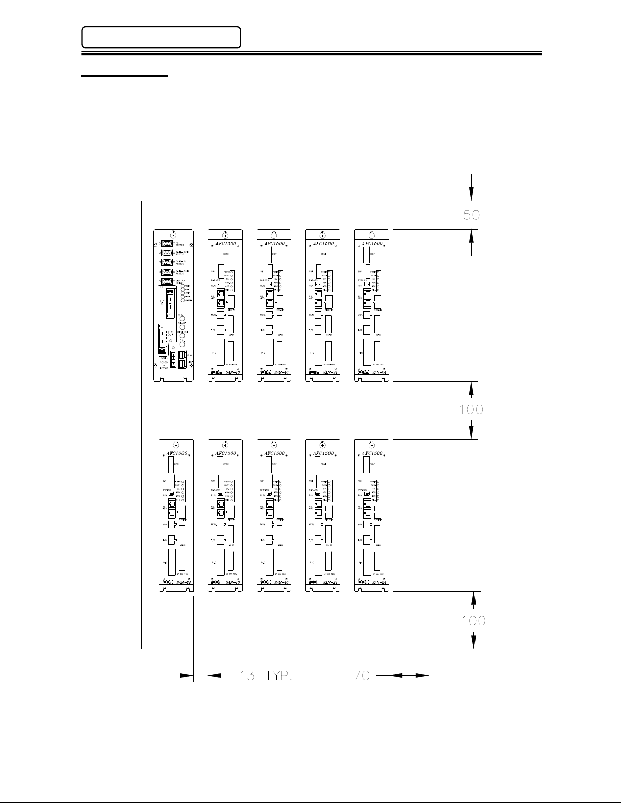
Multi-2 Units must be mounted with a minimum clearance of 13mm on each side to allow proper heat
dissipation. Cable connections on the front of the units require 100mm of clearance. Allow a minimum
of 100mm clearance on the bottom of the unit for flash connector hook up when updating firmware.
The Multi-2 Unit should be mounted into a NEMA12 / IP52 enclosure at a minimum and spaced similar
to the AFC1500 SAN Units (typical installation example shown below).
(See Section 2.2 for Unit Dimensions)
PAGE 4 - 2
Page 3
AFC1500 Multi-2 Unit Hardware Manual (Rev. 2)
Chapter 4: Installation & Wiring
4.2 Power Wiring Reference
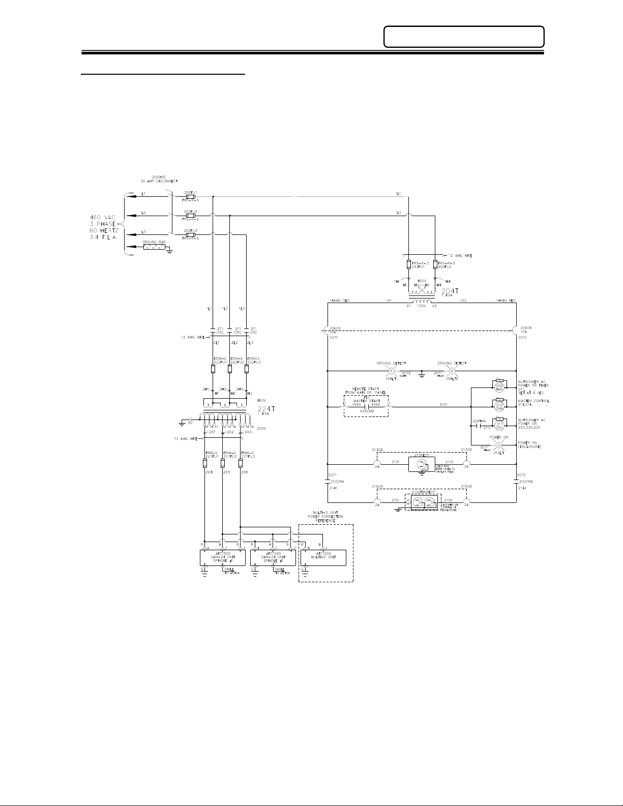
Even though the Multi-2 Unit power input allows it to connect to 120 VAC ~ 220 VAC power lines,
typically the unit is connected to the same power source that the SAN Units are connected to (200 to
220 VAC ± 10%) . In the example wiring diagram shown below there are two power branches; one is
for the control circuitry connected to 120 VAC and the other is for the SAN power circuitry connected
to 220 VAC. For convenience, the Multi-2 Unit is wired together with the AFC1500 Servo Controllers.
Note that the Multi-2 Unit is using one phase while the Servo Controllers use three phases.
PAGE 4 - 3
Page 4
Chapter 4: Installation & Wiring
RS485 port specifications
(RJ45)
Protocol
Proprietary
2
1
8
AFC1500 Multi-2 Unit Hardware Manual (Rev. 2)
4.3 Input Power Connection
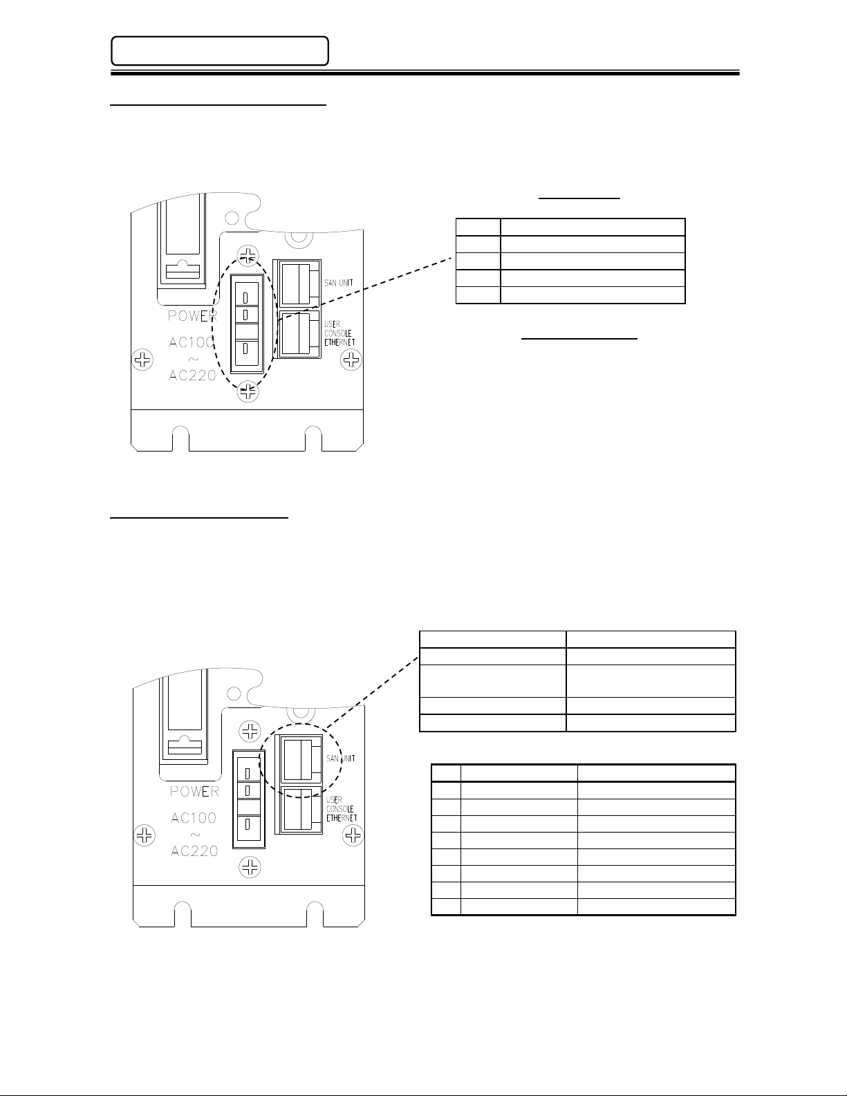
An auto sensing power supply allows for input power in the range of 100 ~ 220VAC single phase,
50/60 hertz. Adequate circuit protection must be provided. Recommended conductor size should be
a minimum of #18AWG.
Wiring Chart
4
3
2
1
Pin Description
4
3 100 ~ 220VAC +/-15%
100 ~ 220VAC +/-15%
No Connection **
Frame Ground
Mating Connector
Manufacture: Amp
Housing Part No.: 1-178128-4
Contact Part No.: 1-175218-3 (Qty.-3)
** To standardize components, FEC cable part
#FEB-1260 may be used due to the fact that
pin #2 is not connected internally.
4.4 RS485 Connection
The Multi-2 Unit uses an RS485 port to perform the communication operations with the AFC1500
Servo (SAN) Controllers. This port has two channels CH1 and CH2. CH1 is dedicated to handle all
preset data upload and download, fastening results monitoring and collection. Channel CH2 is a high
speed connection to all AFC1500 Servo Controllers. It controls all required commands to perform the
fastening cycle.
Speed 9600, 19200, 38400 baud
Cable Std Cat 5 Ethernet
Maximum number of
connected devices
31
Operating Voltage RS485 Standard
RS485 Wiring
NO Signal Name Channel
1 TX+ / RX+ CH1
2 TX- / RX- CH1
3 RX+ CH2
4 TX- CH2
5 TX+ CH2
6 RX- CH2
7 GND
8 GND
PAGE 4 - 4
Page 5
AFC1500 Multi-2 Unit Hardware Manual (Rev. 2)
Ethernet
port specifications (RJ45)
8
Chapter 4: Installation & Wiring
4.5 User Console Ethernet Connection
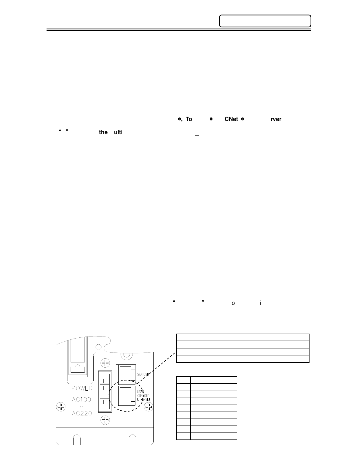
The “User Console Ethernet” port is a dedicated TCP/IP ethernet port for communicating with the
AFC User Console Software in a Windows® based PC. Similar to the serial RS232 (PC) port
dedicated for the AFC Software connection, this port allows connection in an ethernet environment vs.
using the standard serial port connection in previous versions of the Multi Unit. This port allows the
user to set-up, monitor, save data, display and print fastening data and setup parameters using the
AFC User Console software. The ethernet connection allows connection to multiple Multi-2 units
using an ethernet switch or hub. (Different IP addresses must be configured for multiple connection).
NOTE: An additional ethernet port is available for communicating fastening resultant data to
external data collection systems (ie. QDas
custom protocols). This is an OPTIONAL ethernet port and can be ordered by adding the
E
option to the Multi-2 Unit. (Part #1500Multi2E-x)
The default IP address is set at FEC or it can be configured by the user using the AFC User Console
software. If connection cannot be established using the default IP address, the IP address may
have been changed. The default IP address can be re-established by resetting it. See section
4.8.1 for resetting the IP address back to the default setting. The Multi-2 IP address may also be
uploaded, viewed and modified using the AFC software PC connected serially. (RS232 PC Port or
RS485 SAN UNIT connection) Once the current IP address configuration is verified using a serial
connection, then connection may be attempted using the Ethernet port.
Default IP Address of Multi 2 unit
IP Address: 192.168.10.10
Subnet Mask: 255.255.255.0
Default Gateway: 192.168.10.1
Note: Set-up the TCP/IP properties in the computer that will connect to the Multi-2 unit prior to
attempting ethernet port connection. The actual IP address setup in the computer must be a different
number than the Multi-2 unit IP address. Example: Using the default IP address above, set the PC
IP address to 192.168.10.50. Use the same Subnet & Gateway settings)
Note: Only one AFC Software connection method may be used at any given time whether
serial connection or Ethernet connection. The AFC Software can only be configured for one
connection port at a time. If more than one connection is required at the same time (to
additional Multi Units), additional AFC software may be installed and run at the same time,
each set-up with different communication connections.
The connecting cable is a standard Ethernet Crossover cable if connected directly to a PC (FEC
Part #FEB-1331-6). If connected through an Ethernet switch, a standard ethernet CAT5 or CAT5e
may be used (FEC Part Number FEB-1258-6).
, ToolsNet
, FECNet
, SQL Servers or other
Speed 10/100Mbps (auto select)
Cable Std Cat 5 Ethernet
Protocol Proprietary
Operating Voltage Ethernet Standard
Ethernet Wiring
Pin Signal Name
1 Tx+
2 Tx 3 Rx+
4 5 6 Rx 7 8 -
PAGE 4 - 5
Page 6
Chapter 4: Installation & Wiring
AFC1500 Multi-2 Unit Hardware Manual (Rev. 2)
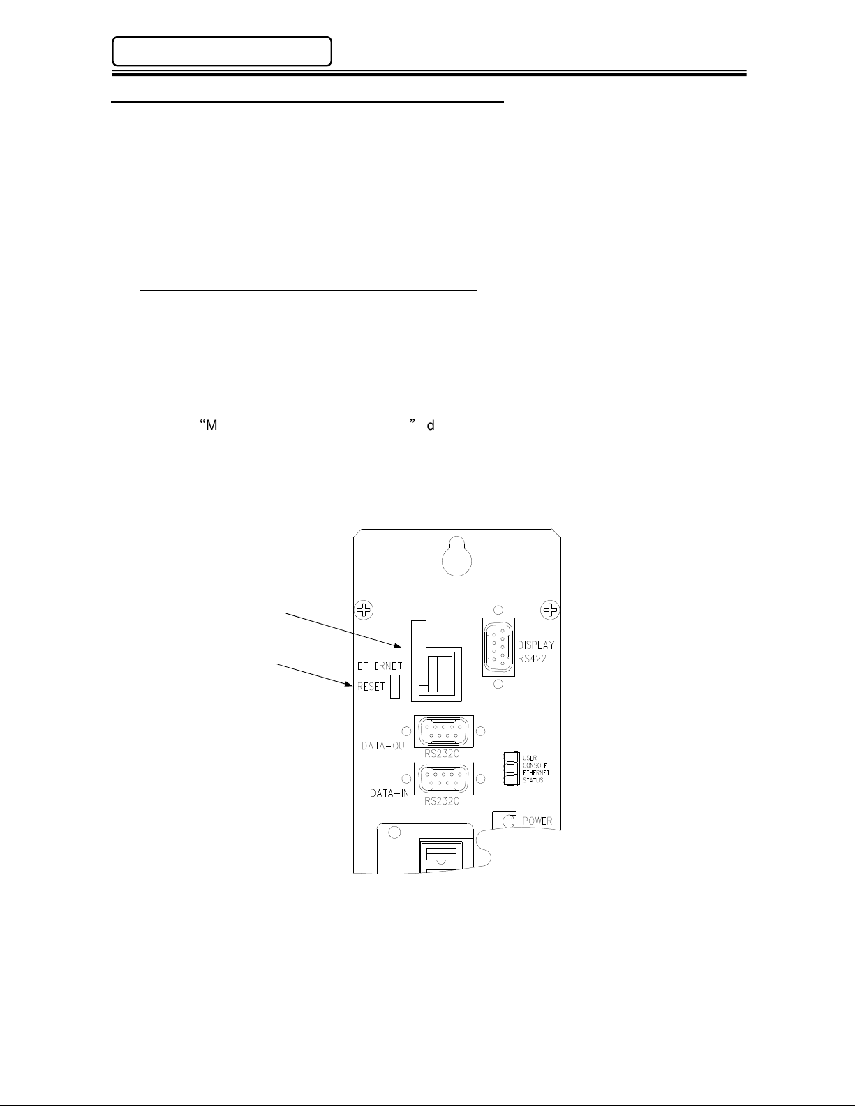
4.5.1 Optional Ethernet Port – Data Communication
As an option, an additional ethernet port is available for sending fastening resultant data over an
ethernet TCP/IP connection. This port can be configured using a standard web browser for
communication to Atlas Copco Toolsnet networks, FEC NET or custom protocols. Additionally,
once configured, the AFC User console software can also communicate over this port.
NOTE: Only one ethernet port may be used to communicate to the AFC software. Either the
dedicated User Console Ethernet port (located in the lower right corner of the front face) or the
optional Ethernet port.
Default IP Address of the Multi 2 Optional Ethernet Port
IP Address: 192.168.10.40
Subnet Mask: 255.255.255.0
Default Gateway: 192.168.10.1
If communication cannot be established using these settings, the settings may have been changed
in the Ethernet Port. To reset the setting back to these default settings, press the RESET
pushbutton located beside the ethernet port while powering on the unit.
See the MULTI 2E SETUP PROCEDURE document for more information when using this port.
(Contact FEC)
Optional Ethernet Port
Default Reset Button
PAGE 4 - 6
Page 7
AFC1500 Multi-2 Unit Hardware Manual (Rev. 2)
Chapter 4: Installation & Wiring
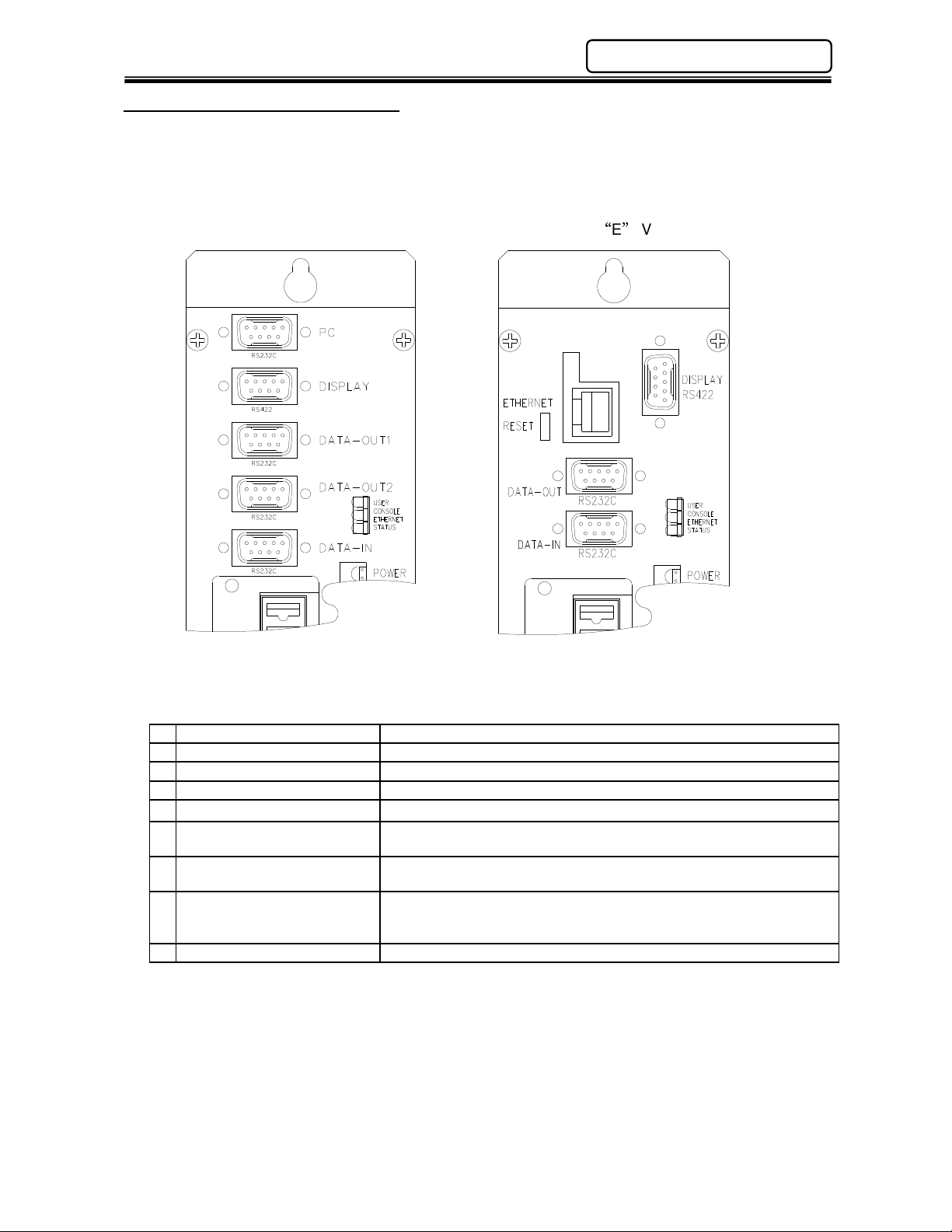
4.6 Serial Communication Ports
The Multi-2 Unit has three usable serial RS232C and one RS422 communication ports. All of the
serial port settings and data format are fully configurable with the AFC User Console software.
When the optional “E” ethernet version is used, the PC & DATA-OUT2 ports are removed.
STANDARD VERSION PORT LAYOUT ETHERNET VERSION PORT LAYOUT
(Optional E Version)
RS-232C Signal Layout
1 DCD (Data Carrier Detect) Used only for DATA-IN*
2 RXD (Receive Data) Serial Data Input.
3 TXD (Transmit Data) Serial Data Output.
4 DTR (Data Terminal Ready) Output signal; active when the internal device is ready to link.
5 GND (Ground Signal)
6 DSR (Data Set Ready)
7 RTS (Request to Send)
8 CTS (Clear to Send)
9 RI (Ring Indicator) Not used
* All Multi-2 serial port connectors are MALE.
Input signal; indicates that the external device is ready to establish a
link. Can be connected directly to DTR for automatic data dump.
Output signal. Active when the internal device is ready to exchange
data.
Input signal. Indicates that the external device is ready to exchange
data. Can be connected directly to RTS when no asynchronous data
flow is required.
PAGE 4 - 7
Page 8
Chapter 4: Installation & Wiring
AFC1500 Multi-2 Unit Hardware Manual (Rev. 2)
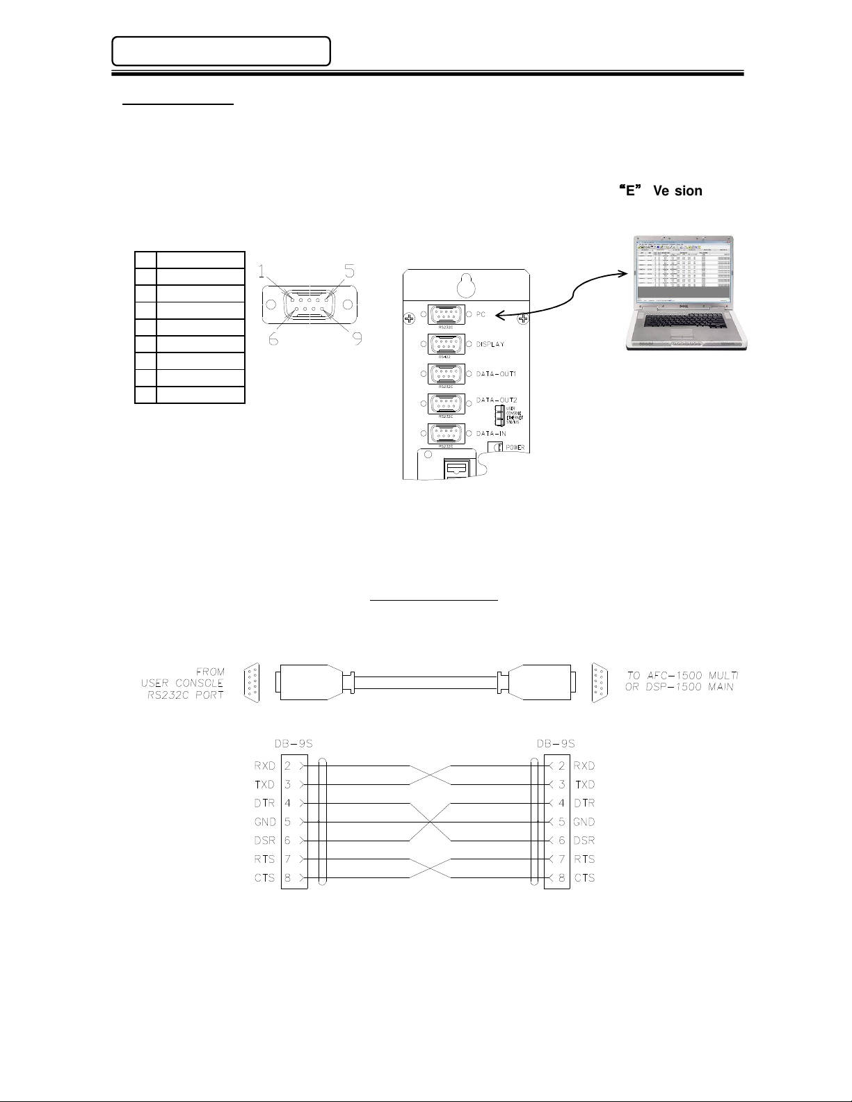
4.6.1 PC Port
The “PC” port is for communicating with the AFC User Console Software PC. The connecting cable
is a standard RS232 Null-Modem cable and can be purchased through FEC (Part #FEB-1301) or
any cable supplier that carries standard 9-Pin Null Modem cables.
Note: This port is removed when using the Ethernet Version (Optional
Unit
RS-232 Pin Layout (Male)
1 DCD
2 RXD
3 TXD
4 DTR
5 GND
6 DSR
7 RTS
8 CTS
9 Not Used
Front View
Standard Null
Modem Cable
E
Version) Multi
PC running AFC
User Console Software
RS-232C PC CABLE
(Standard NULL MODEM Cable)
PAGE 4 - 8
Page 9
AFC1500 Multi-2 Unit Hardware Manual (Rev. 2)
Chapter 4: Installation & Wiring
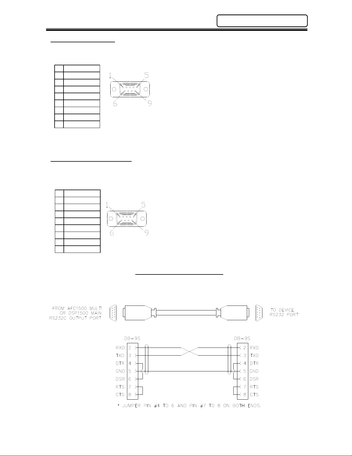
4.6.2 DISPLAY Port
“DISPLAY” port is currently not used in the US Market.
RS-422 Pin Layout (Male)
1 TX+
2 TX-
3 RX+
4 RX-
5 GND
6 Not Used
7 Not Used
8 Not Used
9 Not Used
Front View
4.6.3 DATA-OUT (1) Port
“DATA-OUT(1)” is an output port for ASCII fastening data communication to external devices.
Information concerning available data and data format is shown in the following sections.
RS-232 Pin Layout (Male)
DCD
1
2 RXD
3 TXD
4 DTR
5 GND
6 DSR
7 RTS
8 CTS
9 Not Used
The following cable diagram shows connection for “dumping” data after a fastening cycle. The
output data configured (using the AFC Software) for the DATA-OUT 1 port will be reported
automatically after the fastening cycle ends.
Front View
RS-232C DATA-OUT 1 & 2 CABLE
PAGE 4 - 9
Page 10
Chapter 4: Installation & Wiring
Basic
Fastening Data
Length in bytes
Extended Fastening Data
Length in bytes
Input Data*
Length in bytes
System Data
Length in bytes
AFC1500 Multi-2 Unit Hardware Manual (Rev. 2)
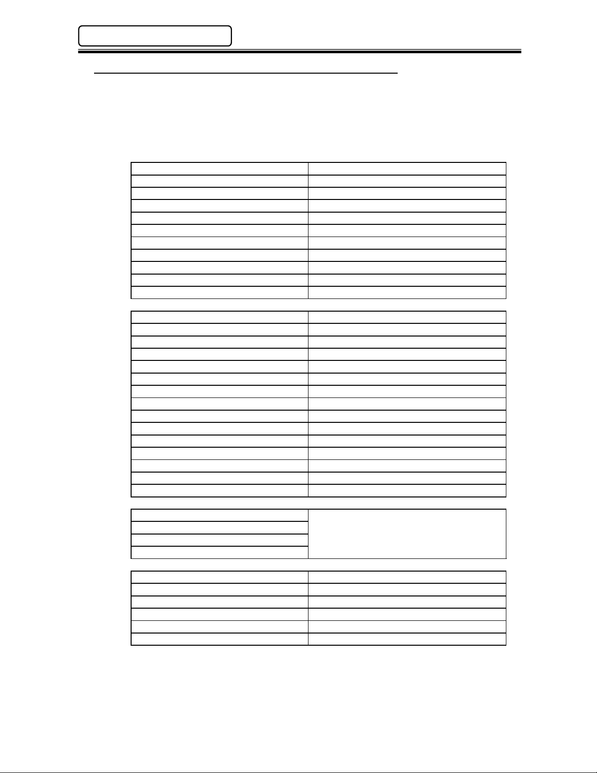
4.6.3.1 Available Output Data (From DATA-OUT 1 Port)
The Multi-2 Unit is capable of outputting the fastening results data in an ASCII format to a serial
printer or other serial peripheral devices. The data is sent from the Multi-2 Unit’s RS232C “DATA
OUT - 1” port. The output data string format as well as port configuration can be configured using
the AFC User Console Software. As little as one data item or up to all items can be user
configured. ASCII Control Characters may also be implemented (Ex: Start of Text, End of Text,
etc.). Below is a list of data available and its byte length.
Peak Torque
Final Angle
First Time
Final Time
Cycle Time
First Torque Rate
Second Torque Rate
Third Torque Rate
Final Torque
Offset Torque
Judgment
Current (@ peak torque) 4
Angle (@ peak torque) 4
First Peak Torque 5
Second Peak Torque 5
First Torque Rate Increment Torque 5
First Torque Rate Increment Angle 4
Second Torque Rate Increment Torque 5
Second Torque Rate Increment Angle 4
Third Torque Rate Increment Torque 5
Third Torque Rate Increment Angle 4
Rundown revolutions 4
Cal Voltage Value 5
Zero Voltage Value 5
Judgment 2
Retry Flag 3 (ASCII “RTY”)
RS232C data buffer 1
RS232C data buffer 2
RS232C data buffer 3
RS232C data buffer 4
Date 10
Time 8
Spindle Number 2
Sequence Number 2
Parameter Number 2
Cycle Count Number 7
Up to 128
This length is determined by the user and
dependent upon the length of data input to
these data areas.
6
5
6
6
5
7
7
7
5
5
3
*Input Data is input to the Multi-2 Unit using the RS232C “DATA INPUT” port. This port is
configured through the AFC User Console Software. The data must be ASCII formatted data & is
limited to 128 bytes in (4) separate data buffers. The port must be configured for the input string
which is to be received. The data received can then be married with the resultant fastening data by
selecting the RS232 data in the output format. This function is typically used to marry a part
number with the resultant fastening data for production birth history.
PAGE 4 - 10
Page 11
AFC1500 Multi-2 Unit Hardware Manual (Rev. 2)
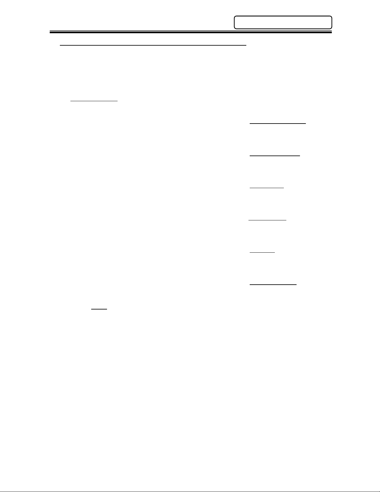
4.6.3.2 Output Data Format (From DATA-OUT 1 Port)
The example below shows the format of the DATA-OUT (1) port connected to a printer. Actual
data output format may vary depending on the configuration and set-up of this port using the AFC
User Console Software. The data field is selectable from as little as one output field to all available
data (see previous table for available data fields). Headers, footers & ASCII control characters are
all user configurable using the AFC User Console Software.
EXAMPLE ONLY – Actual data will depend on individual user set-up.
2007/09/26 09:17:57 SEQ01 [Input Data from DATA-IN if programmed here]
SP PA TORQUE ANGLE 1RATE 2RATE OFSET JUG Acceptable Fastening
01 01 0.50 2 0.000 0.005 0.00 O
2007/09/26 09:19:36 SEQ01
SP PA TORQUE ANGLE 1RATE 2RATE OFSET JUG Rejected Fastening
01 01 0.17L 0 0.000 0.000 0.00 X
2007/09/26 09:21:16 SEQ01
SP PA TORQUE ANGLE 1RATE 2RATE OFSET JUG Reset Cycle
01 01 0.23L 0 0.000 0.000 0.00 * (Before fastening end)
2007/09/26 09:21:21 SEQ01
SP PA TORQUE ANGLE 1RATE 2RATE OFSET JUG Cycle Stopped
01 01 0.17L 0 0.000 0.000 0.00 ! (Before fastening end)
2007/09/26 09:21:34 SEQ01
SP PA TORQUE ANGLE 1RATE 2RATE OFSET JUG Abnormal
01 01 0.01 0 0.000 0.000 0.00 A05 (Showing abnormal code)
2007/09/26 09:21:21 SEQ01
SP PA TORQUE ANGLE 1RATE 2RATE OFSET JUG Spindle Bypassed
01 00 0. 0. 0. 0. 0.
Index
SEQ: Sequence 1RATE: 1st Rate H: High
SP: Spindle 2RATE: 2nd Rate L: Low
PA: Parameter OFSET: Offset Torque
ANGLE: Final Angle JUG: Judgment
Chapter 4: Installation & Wiring
PAGE 4 - 11
Page 12
Chapter 4: Installation & Wiring
AFC1500 Multi-2 Unit Hardware Manual (Rev. 2)
4.6.4 DATA-OUT 2 Port
“DATA-OUT2” port is currently not used.
RS-232 Pin Layout (Male)
1 DCD
RXD
2
3 TXD
4 DTR
5 GND
6 DSR
7 RTS
8 CTS
9 Not Used
Note: This port is removed when using the Ethernet Version (Optional
Front View
E
Version) Multi
Unit
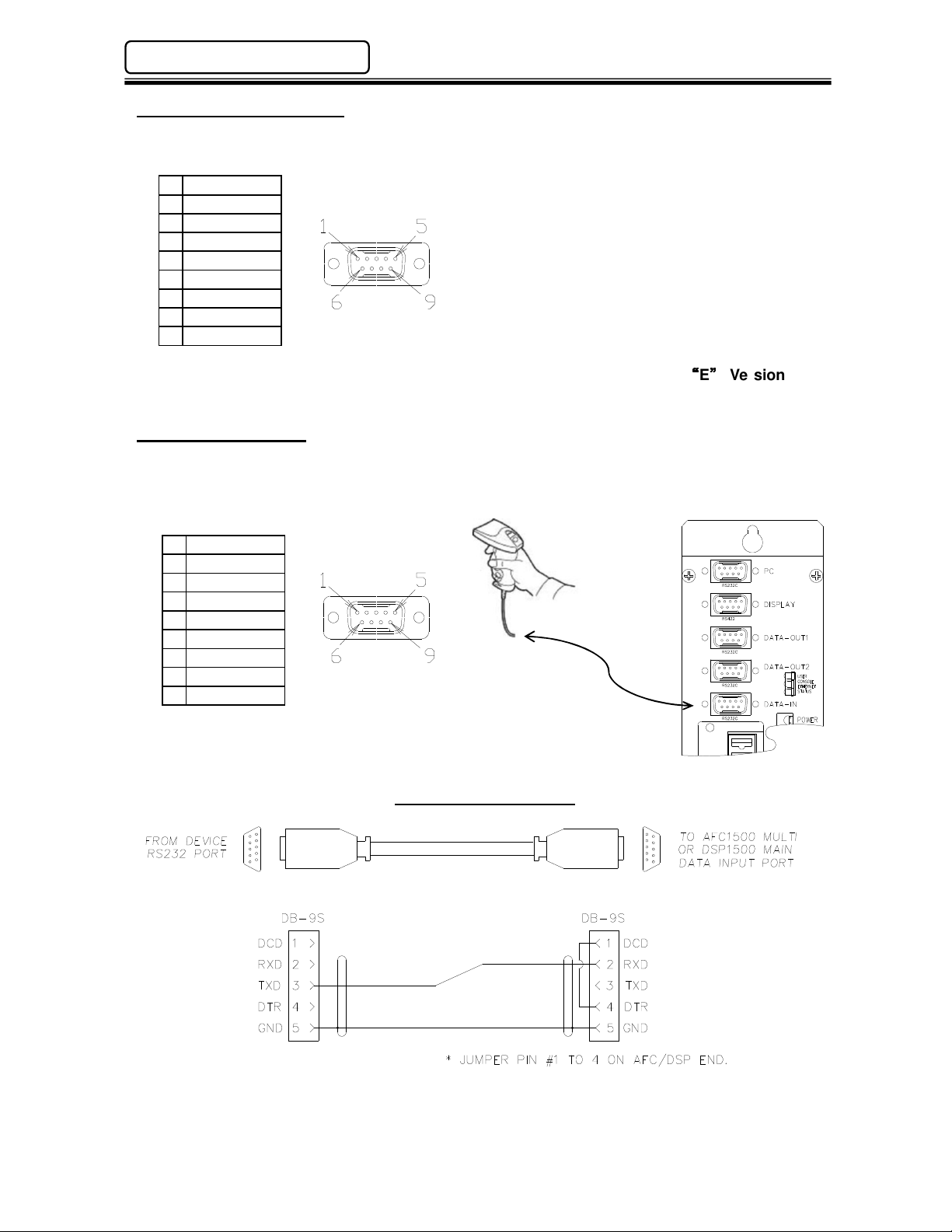
4.6.5 DATA-IN Port
The “DATA-IN” port is for inputting ASCII data to the fastening system for marriage to the fastening
data. It is typically used for attaching part serial number(s) to the fastening data for data storage
birth history.
RS-232 Pin Layout (Male)
1 DCD
2 RXD
3 TXD
4 DTR
5 GND
Not Used
6
7 RTS
8 CTS
9 Not Used
Front View
RS-232C DATA-IN CABLE
* When using the DATA-IN port, PIN 1 (DCD) must be enabled for data input (Jumper pins 1 & 4).
PAGE 4 - 12
Page 13
AFC1500 Multi-2 Unit Hardware Manual (Rev. 2)
Base Pa
rt
1500MULTI2(E)
1500MULTI2(E)
*1500MULTI2E
1500MULTI2(E)
*1500MULTI2E
1500MULTI2(E)
*1500MULTI2E
1500MULTI2(E)
1500MULTI2(E)
®
1500MULTI2(E)
1500MULTI2(E)
1500MULTI2(E)
1500MULTI2(E)
®
1500MULTI2(E)
1500MULTI2(E)
Chapter 4: Installation & Wiring
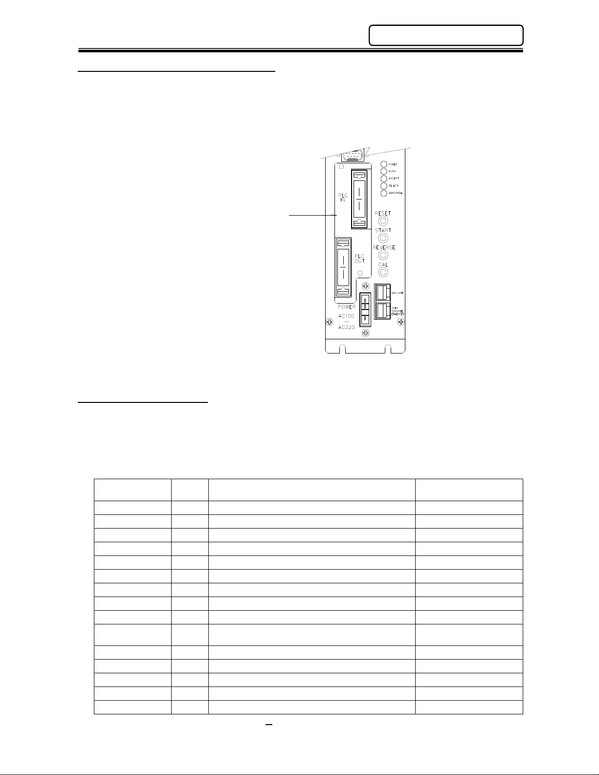
4.7 PLC Input/Output (I/O) Interface
The Multi-2 Unit is able to operate under different Input/Output control structures through use of a
modular I/O interface board installed in the unit. Besides standard discrete “hardwired” interface
signals, the introduction of “Open” architecture communication networks known as “Fieldbus” made it
necessary for the direct interfacing to these networks. FEC integrated many Fieldbus interfaces
directly into our system through use of a modular I/O board interfacing these networks directly to our
I/O. (See Chapter 5 for available interfaces)
Interface Board
Discrete I/O interface shown above
4.7.1 Control Interfaces
The available I/O interfaces are shown in the chart below. The fieldbus interface boards are integrated
directly to internal I/O signals which eliminate associated I/O wiring thus reducing overall assembly
labor. In fieldbus systems, the communication is typically of the Master/Slave format in which the FEC
unit is a slave to the master CPU. In addition to handling I/O signals, some Fieldbus types allow
resultant fastening data to be sent over the same connection to the host PLC (Described below as I/O
& Messaging)
Number
Suffix Description Special Requirements
-1 Discrete I/O (Sinking Type)
-2 Discrete I/O (Sourcing Type)
-3
DeviceNet-S® (for Toolsnet®)
-4 Profinet IO (I/O & Messaging)
-5
Interbus-S® (for Toolsnet®)
-6 Allen Bradley Remote I/O®
-7
Profibus® (for Toolsnet®)
-8
Modbus Plus®
-9
DeviceNet-S
-10 Ethernet I/P (I/O & Messaging)
-11
-12
-13
-14
-15 M-Net
Interbus-S®
Mitsubishi CC-Link® Ver. 2 (I/O & Messaging)
Profibus
Mitsubishi CC-Link Ver. 1® (I/O only)
(I/O & Messaging)
(I/O & Messaging)
Hardware V1.09 or later
Hardware V1.09 or later
Hardware V1.09 or later
Hardware V1.12 or later
Software V4.16 or later
Software V4.13 or later
*Toolsnet Interface available for Multi2E (optional ethernet) version only. See Toolsnet Interface
Manual for set up information. (Other interfaces available – Contact FEC)
PAGE 4 - 13
Page 14
Chapter 4: Installation & Wiring
Sequence Select 1
Resetting the counter value requires
a 200~
500ms pulse.
BYPASS Spindle No.9
AFC1500 Multi-2 Unit Hardware Manual (Rev. 2)
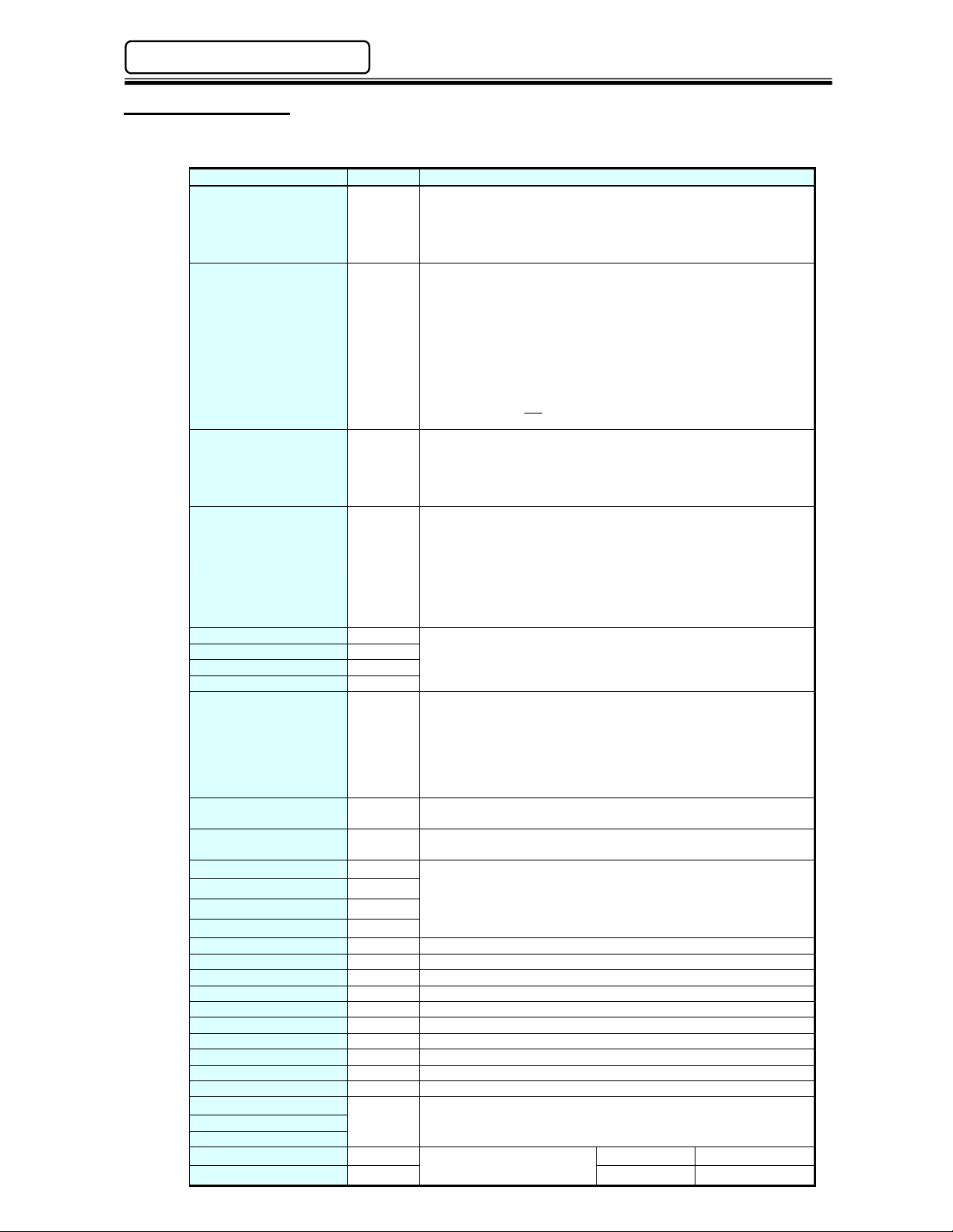
4.7.2 Input Signals
The list below contains a description of the Input signals available on the I/O interface. Further input
mapping can be found in the individual interface information (See Chapter 5).
Signal
Emergency Stop N.C.
Reset N.O.
Reverse N.O.
Start N.O.
Sequence Select 0 N.O.
Sequence Select 2 N.O.
Sequence Select 3 N.O.
Cycle Count Up N.O.
Cycle Count Clear N.O.
Self Check Disable N.O.
INPORT 1 N.O.
INPORT 2 N.O.
INPORT 3 N.O.
INPORT 4 N.O.
BYPASS Spindle No.1 N.O. Bypass’s spindle #1 - Spindle is ignored as if it does not exist.
BYPASS Spindle No.2 N.O. Bypass’s spindle #2 - Spindle is ignored as if it does not exist.
BYPASS Spindle No.3 N.O. Bypass’s spindle #3 - Spindle is ignored as if it does not exist.
BYPASS Spindle No.4 N.O. Bypass’s spindle #4 - Spindle is ignored as if it does not exist.
BYPASS Spindle No.5 N.O. Bypass’s spindle #5 - Spindle is ignored as if it does not exist.
BYPASS Spindle No.6 N.O. Bypass’s spindle #6 - Spindle is ignored as if it does not exist.
BYPASS Spindle No.7 N.O. Bypass’s spindle #7 - Spindle is ignored as if it does not exist.
BYPASS Spindle No.8 N.O. Bypass’s spindle #8 - Spindle is ignored as if it does not exist.
BYPASS Spindle No10 N.O. Bypass’s spindle #10 - Spindle is ignored as if it does not exist.
Data Select 0
Data Select 1 N.O.
Data Select 2
Input Signal Power
Input Signal Power Source Type +0V
Contact Description
Emergency Stop Input.
Signal MUST be Active to perform a fastening operation.
When this signal is inactive (off), all Multi-2 Unit operation ceases,
all spindles in motion will stop, and all communication ports &
input/outputs will be disabled.
Reset Input.
When active (on), this signal will clear all spindle data and
discrete outputs. A Zero Check of all torque transducers will be
completed. During the Zero Check, the CHECK lamp will
illuminate, the READY signal will turn OFF, and the ACCEPT or
REJECT lamp will light to indicate the result of the Zero Check. If
the System has been disabled by an Abnormal output, the
System will not return to normal operation until the Abnormal
condition has been corrected, and this signal has been input for
200~500ms. Do not input this signal between cycles as part of an
automatic cycle due to the potential for fastening data loss.
Reverse Spindle Rotation Input.
All spindles will rotate in an opposite direction (of fastening) for as
long as this signal is activated (on) and maintained. The Reverse
input functions the same as the reverse pushbutton on the front of
the Multi-2 Unit.
Start Cycle Input.
The Start input automatically resets the previous cycle, clears all
data to zero, and initiates the next fastening cycle. The start input
requires a pulse of 200~500 milliseconds if the Multi-2 Unit is set
up for AUTOMATIC Start input. If it is set up for DEADMAN
(hand-held operation) input, the Start input must be maintained
"on" for the entire cycle. Typically this signal is held on until
confirmation of the “Busy” signal is received.
N.O.
N.O. Bypass’s spindle #9 - Spindle is ignored as if it does not exist.
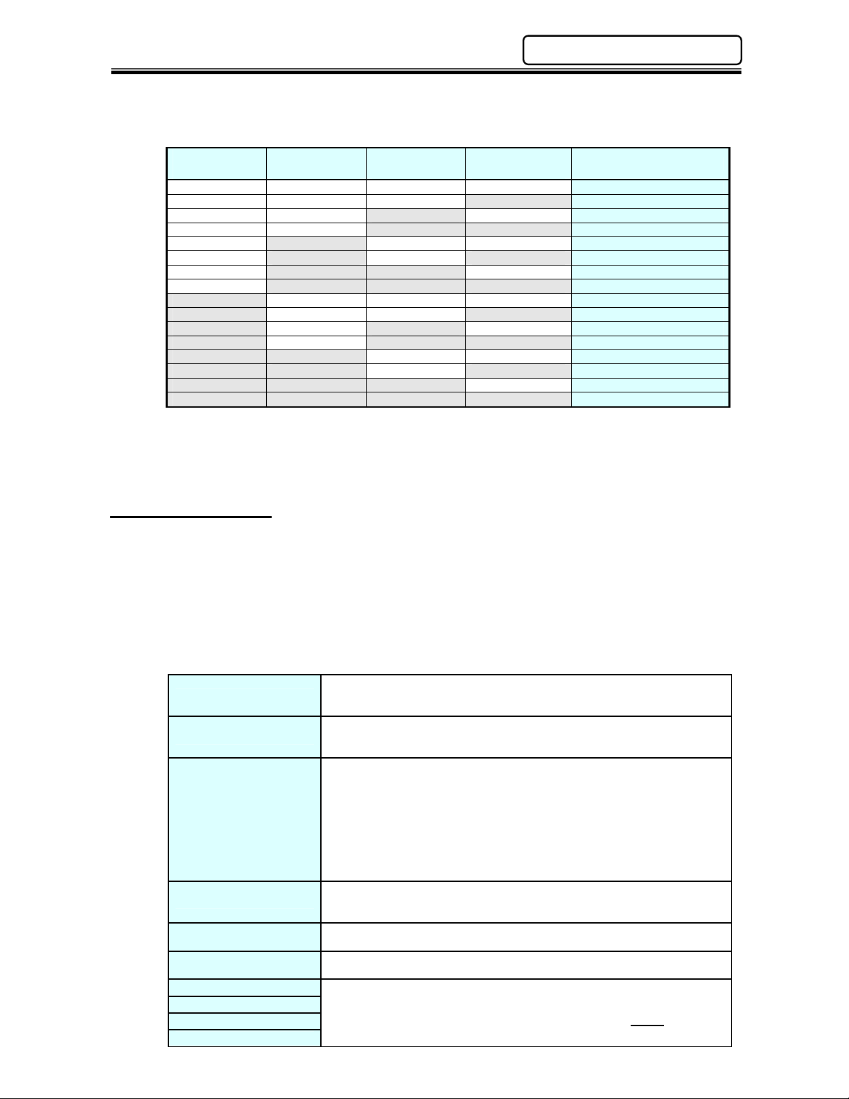
Sequence Select Input.
These 5 inputs form a binary code which is capable of selecting
up to 16 different operation sequences. Refer to Table 1. (Can be
used for part model selection)
Cycle Count Input.
The System cycle counter will increment each time this signal is
input if the CYCLE COUNT UP is set to PLC SIGNAL in the
Multi-2 Unit. The Cycle Count input requires a pulse of 200~500
milliseconds to increment the counter. If the CYCLE COUNT UP
is set to AUTO, the cycle counter increments automatically at the
end of every fastening.
The internal cycle counter is reset when this signal is input.
Disables the Calibration & Zero Level check that automatically is
performed at the start of each cycle
External Sequence Input.
These four (4) signals are external inputs to the fastening
sequence. When a [PLC INPUT WAIT] instruction is programmed
in the fastening sequence, it will stop until the designated external
input is active.
These 3 inputs form a binary code to select up to 8 Output Data
Banks. Used for Digital I/O interfaces. NOTE: Not used for
Fieldbus interfaces. [See Table 3 on Page 5-12]
Common for input signal.
Sink Type +24V
PAGE 4 - 14
Page 15
AFC1500 Multi-2 Unit Hardware Manual (Rev. 2)
OFF ON OFF ON 6
ON ON OFF OFF 13
(Continued)
[Table 1 – Sequence Selection]
Sequence
Select 3
OFF OFF OFF OFF 1
OFF OFF OFF ON 2
OFF OFF ON OFF 3
OFF OFF ON ON 4
OFF ON OFF OFF 5
OFF ON ON OFF 7
OFF ON ON ON 8
ON OFF OFF OFF 9
ON OFF OFF ON 10
ON OFF ON OFF 11
ON OFF ON ON 12
ON ON OFF ON 14
ON ON ON OFF 15
ON ON ON ON 16
Sequence
Select 2
Sequence
Select 1
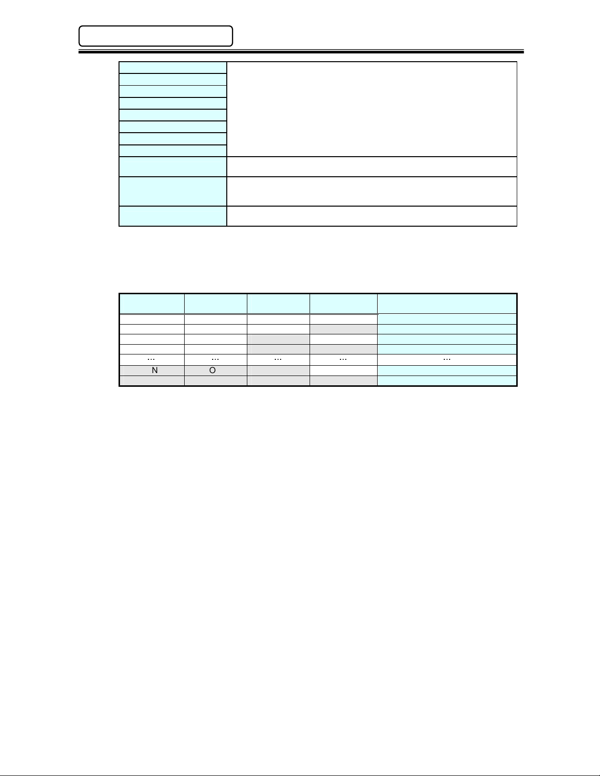
4.7.3 Output Signals
The list below contains a description of the output signals available on the I/O interface. Further
output mapping can be found in the individual interface information (See Chapter 5). The
Multi-2 Unit is capable of providing over 570 Output signals to indicate the status of the Multi-2
Unit and of all the AFC1500 SAN Controllers connected to it (up to 31 controllers). These
signals are user configurable using the AFC User Console Software and may be programmed
on any designated output bit.
Main Multi Unit Output Signals
Total Reject
Total Accept
Abnormal
Ready
Busy
End
Sequence 0
Sequence 1
Sequence 2
Sequence 3
Output when the fastening result is a REJECT. Indicates that one or more
spindles have failed achieving the fastening limits. This output remains active
until the START signal or RESET signal is input.
Output when the fastening result is a ACCEPT. Indicates all spindles are
within fastening limits. This output remains active until the START signal or
RESET signal is input.
Output when an Abnormal condition occurs. This signal indicates that the
System has detected an internal fault, and can no longer proceed. The fault
maybe generated from a connected spindle during a self-check function.
Check the individual spindle status to identify which spindle is reporting the
abnormal condition. (see AFC1500 Operation Manual for troubleshooting)
The spindle reporting an abnormal may be bypassed to resume normal
operation, however, the bypassed spindle will be ignored and not run while in
bypass. An Abnormal condition must be corrected before the System will
resume normal operation. The RESET signal clears the abnormal condition.
Output when the system is in the READY condition. Indicates system is ready
to operate, and inputs are enabled. This signal is inactive (off) when the
BUSY output is active (on).
Output after a START signal is received, and active until the fastening cycle is
complete and the READY signal is output.
Output when a fastening cycle is complete. Remains active until the START,
RESET or REVERSE signal is input.
Output confirmation of SEQUENCE SELECT 0~4 input selections.
Sequence bits are active according to what sequence is set from the
sequence select inputs. Used to confirm proper sequence before fastening
starts. Refer to Table 3.
Chapter 4: Installation & Wiring
Sequence
Select 0
Selected Sequence No.
PAGE 4 - 15
Page 16
Chapter 4: Installation & Wiring
OFF OFF OFF ON 2
AFC1500 Multi-2 Unit Hardware Manual (Rev. 2)
Out Port 1
Out Port 2
Out Port 3
Out Port 4
Out Port 5
Out Port 6
Out Port 7
Out Port 8
Spindle in Bypass
Current Limit Warning
Always ON / OFF
These signals will output when the fastening sequence reaches a step that
has a [PLC OUTPUT] instruction inserted. Used to provide sequence
operation status to external PLC’s and/or control outputs for slide motion,
lights, & buzzers, etc without the use of a PLC. (The AFC User Console
Software can set these outputs on and off in the fastening sequence)
Signal is active when any of the connected spindles are bypassed either from
San Unit bypass input signals or from the San Unit bypass switch.
Active when the high current limit has been exceeded. This can be used to
identify potential motor failure before total failure occurs by identifying high
current draws over what the typical current draw is for the application.
Can be used to set outputs ON or OFF. Typically used in conjunction with
Bank Outputs to monitor which Bank is selected.
[Table 2 – Sequence Select Output]
Sequence
Output 3
OFF OFF OFF OFF 1
Sequence
Output2
Sequence
Output1
Sequence
Output0
Selected Fastening
Sequence No.
OFF OFF ON OFF 3
OFF OFF ON ON 4
ON ON ON OFF 15
ON ON ON ON 16
PAGE 4 - 16
Page 17
AFC1500 Multi-2 Unit Hardware Manual (Rev. 2)
fastening cycle is complete and the READY signal is output.
value
.
Current Limit
Low
Chapter 4: Installation & Wiring
(Output Signals – Continued)
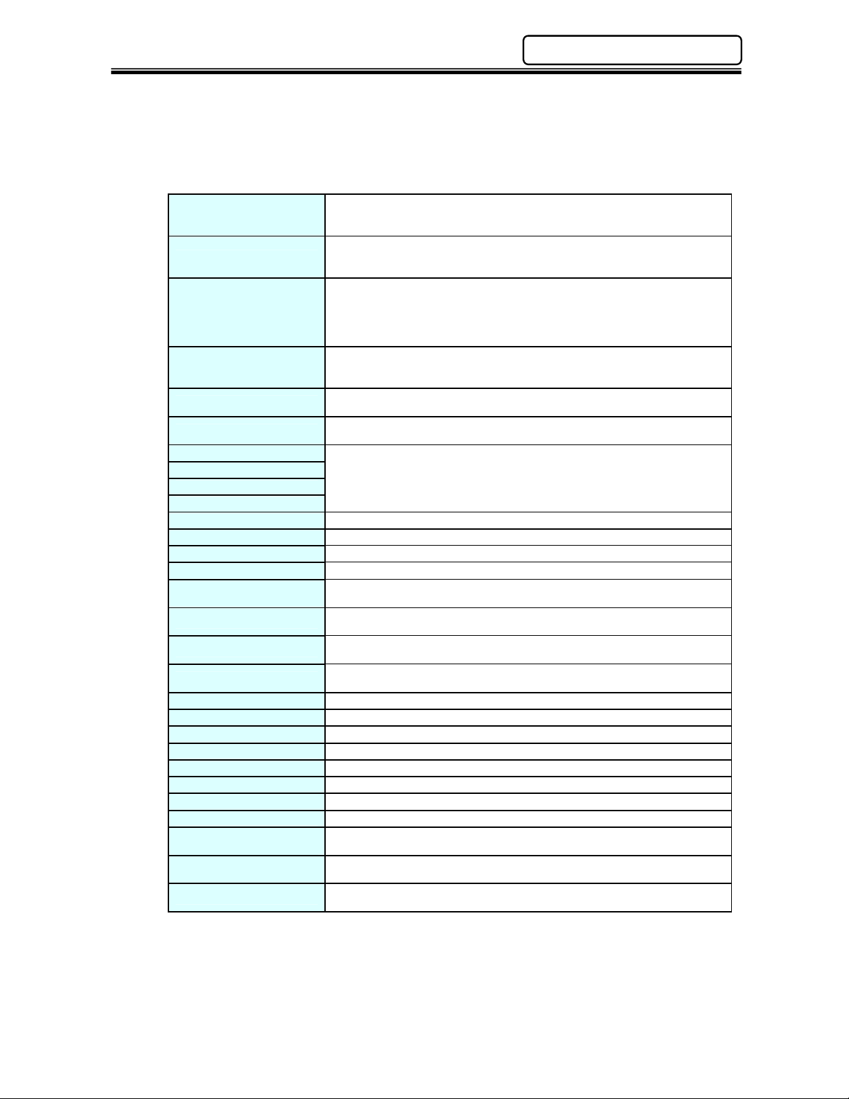
In addition to the main Multi unit output signals, individual spindles that are connected to the Multi unit
report status signals to the Multi Unit. These signals are available on a “per spindle” basis and can
be used or programmed using the AFC User Console software.
Available Individual Spindle Unit Output Signals (Per connected spindle)
Reject
Accept
Abnormal
Ready
Busy
Bypass
Parameter Select 1
Parameter Select 2
Parameter Select 3
Parameter Select 4
Time 1 Low Reject Output when 1st Time result is below the set 1st Time Low Limit value.
Time 1 High Reject Output when 1st Time result is above the set 1st Time High Limit value.
Time 2 Low Reject Output when Final Time result is below the set Final Time Low Limit value.
Time 2 High Reject Output when Final Time result is above the set Final Time High Limit value.
Peak Torque Low Reject
Peak Torque High Reject
Final Torque Low Reject
Final Torque High Reject
Angle Low Reject Output when Angle result is below the set Angle Low Limit value.
Angle Low Reject Output when Angle result is above the set Angle High Limit value.
Rate 1 Low Reject Output when Rate 1 result is below the set Rate 1 Low.
Rate 1 High Reject Output when Rate 1 result is above the set Rate 1 High.
Rate 2 Low Reject Output when Rate 2 result is below the set Rate 2 Low.
Rate 2 High Reject Output when Rate 2 result is above the set Rate 2 High.
Rate 3 Low Reject Output when Rate 3 result is below the set Rate 3 Low.
Rate 3 High Reject Output when Rate 3 result is above the set Rate 3 High.
Warning
Current Limit High
Warning
Combination Bits 1-8
Output when the fastening result is a REJECT. Indicates that the spindle has
failed achieving the fastening limits. This output remains active until the
START signal or RESET signal is input.
Output when the fastening result is an ACCEPT. Indicates that the spindle is
within fastening limits. This output remains active until the START signal or
RESET signal is input.
Output when an Abnormal condition occurs. This signal indicates that the
spindle has detected an internal fault and can no longer proceed. The fault
maybe generated during a self-check function (see AFC1500 Operation
Manual for troubleshooting). The RESET signal clears the abnormal
condition.
Output when the spindle is in the READY condition. Indicates spindle is
ready to operate and inputs are enabled. This signal is inactive (off) when the
BUSY output is active (on).
Output after a START signal is received, and remains active until the
Signal is active when the spindle is bypassed either from San Unit bypass
input signal or from the San Unit bypass switch.
Output confirmation of PARAMETER SELECT 1~4 input selections.
Parameter Select bits are active according to what sequence is set from the
sequence select inputs.
Output when Peak Torque result is below the set Peak Torque Low Limit
value.
Output when Peak Torque result is above the set Peak Torque High Limit
value.
Output when Final Torque result is below the set Final Torque Low Limit
Output when Final Torque result is above the set Final Torque High Limit
value.
Output when the current is below acceptable Limits.
Output when the current is above acceptable Limits.
Used to create “special” outputs formed by using a combination of SAN Unit
outputs in “AND / OR” logic.
PAGE 4 - 17
Page 18
Chapter 4: Installation & Wiring
OFF
ON
OFF
ON
OFF
ON
REVERSE
OFF
ON
Fastening
Fastening
OFF
ON
OFF
ON
OFF
ON
OFF
ON
OFF
ON
OFF
ON
OFF
ON
OFF
ON
OFF
ON
OFF
ON
OFF
ON
OFF
ON
OFF
ON
OFF
ON
OFF
ON
AFC1500 Multi-2 Unit Hardware Manual (Rev. 2)
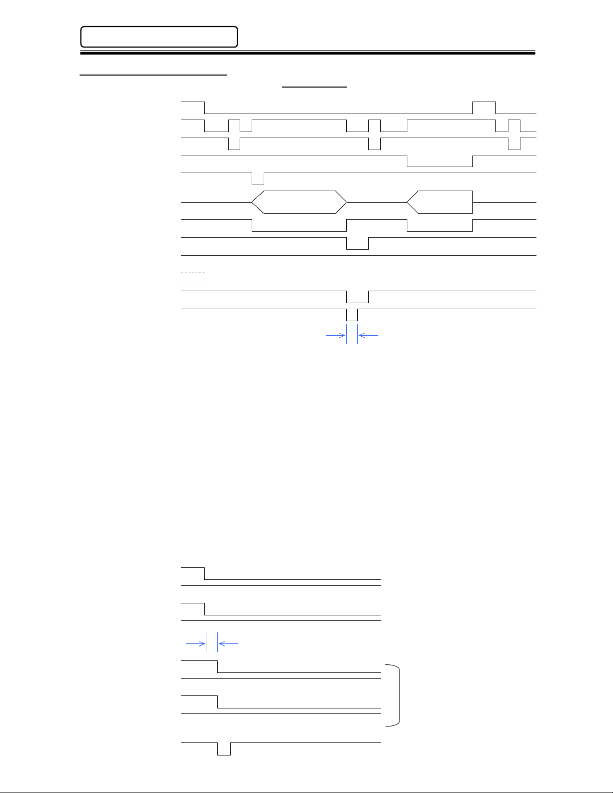
4.7.4 Signal Timing Chart
STOP
Signal Timing
READY
RESET
START
FASTENING
A
A
Operation
Operation
BUSY
ACCEPT
REJECT
ABNORMAL
END
COUNT UP
A
200 ~ 500ms (A)
Because the RESET input clears all fastening data and discrete outputs, it should only be activated
to clear a system Abnormal or to perform a Zero Level Check. The system will automatically reset
with each fastening start. A manual RESET activation between cycles could result in data loss.
The REVERSE signal must be maintained for the duration of the desired REVERSE function.
The STOP input is normally closed and enables all other functions. When open (OFF), all
operations cease and all inputs / outputs become inactive.
The START signal will not operate during RESET, REVERSE or ABNORMAL signal activation. A
pulse of 200~500 milliseconds is required for AUTO START mode. For DEADMAN mode (Used
mainly in handheld applications), the signal must be maintained for the complete fastening cycle
(until BUSY goes low).
When the ABNORMAL signal is activated, the system must be RESET before normal operation will
resume.
REJECT & ACCEPT signals are maintained until the start of the next cycle or on a RESET.
READY indicates when the system is ready to start.
It is recommended when changing sequences that the Sequence Select outputs be used to verify
that the sequence has been changed before issuing a start signal. Delay from Sequence Select
input to Sequence Select output is approximately 5ms.
Seq. Sel. Bit 0
Seq. Sel. Bit 1
Seq. Sel. Bit 2
Sequence Select No. 6
(Multi-2 Inputs)
Seq. Sel. Bit 3
Bit 0 Selected
Bit 1 Selected
Bit 2 Selected
Bit 3 Selected
START
Allow 20ms to interlock the Sequence Select
Command and the associated result signal.
Sequence No. 6 Selected
(Multi-2 Outputs)
* No bit selected = Sequence No. 1
PAGE 4 - 18
Page 19
AFC1500 Multi-2 Unit Hardware Manual (Rev. 2)
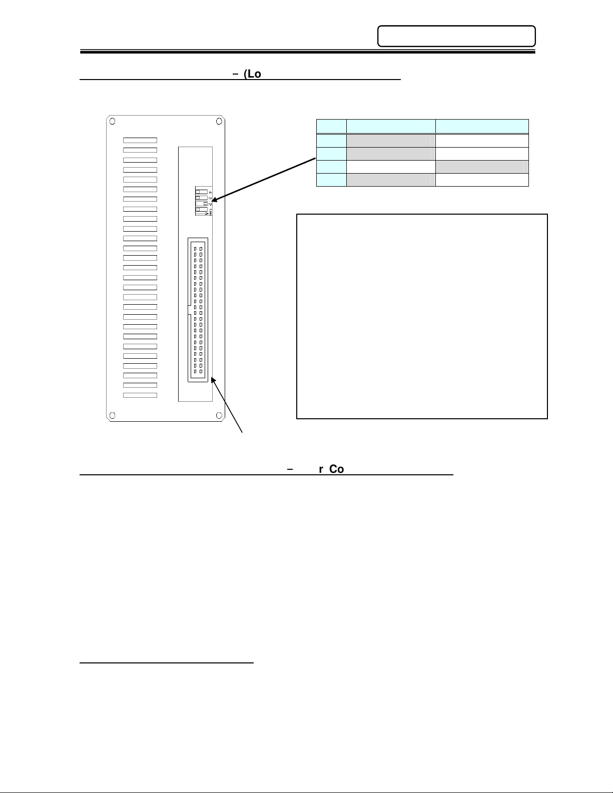
Switch 1: I/O Enable / Disable Test Mode
Chapter 4: Installation & Wiring
4.7.5 External DIP Switch
FRONT
DIP SWITCH (Factory Setting)
(Located on bottom of unit)
No. OFF ON
4
Not Used
3
Not Used
Angle resolution: 0.1 Angle resolution: 1
2
1
EXT. I/O ENABLE EXT. I/O DISABLE
If Switch No.1 is turned ON, the Input / Output Module
will be bypassed and the STOP signal will be enabled
allowing Manual operations through the front panel
buttons for testing purposes. This is particularly
useful when Fieldbus interfaces are installed and
connection to the master device is not possible.
When finished testing the equipment, be sure to
turn Switch No. 1 OFF.
Do not change Switch No. 3 or 4.
Switch 2 : Angle Resolution
Normal angle resolution is 1.0 degree. Angle
resolution of 0.1 degree is available using this switch.
Note: SAN unit firmware version 3.3x is required and
the function enabled if using the AFC User Console for
monitoring purposes.
(Bottom View)
4.8 Setting Default TCP/IP Address
For Multi-2 units with firmware 1.16 or greater, the IP address for the User Console Ethernet Port can be
reset to the default setting by following the directions below.
1. Turn off power to the unit
2. Turn “ON” DIP Switch no. 1, 2 & 4
3. Depress and HOLD the RESET button (on front of unit) and turn the power back on
4. Hold the RESET button until the green ACC LED turns on solid
5. Turn power off and reset DIP Switch back to original setting
When power is reapplied, the TCP/IP settings will revert to the following default;
IP Address: 192.168.10.10
Subnet Mask: 255.255.255.0
Default Gateway: 192.168.10.1
4.9 Firmware Flash Connector
Upgrades or revisions to firmware are handled easily with the on board Flash Connector located on
the bottom of each Multi-2 Unit. There is no need to remove or disassemble the unit. A flash adapter
(CONTROLLER-ROM) containing the new firmware can be connected to connector CN8 with the
power off to the unit. The power is then cycled on until the ACCEPT LED is blinking indicating the
firmware upload is complete. Turn off power and remove the flash adapter. The firmware update is
now complete.
Note: This connector is for FEC use only and it is not recommended for use other than FEC.
Firmware Flash Connector (CN8)
User Console Ethernet Port
PAGE 4 - 19
Page 20

Chapter 4: Installation & Wiring
AFC1500 Multi-2 Unit Hardware Manual (Rev. 2)
(Blank Page)
PAGE 4 - 20
 Loading...