


System Manual
1
Model Name:
AP-3617
Document Version: I
Customer
Checked &
Approved by
Date
FEC
Prepared by
FEC
Approved by
Date
_________

A
Aeerr
P
P
O
O
S
S
U
Usseerr''ss
M
Maa
n
n
u
uaall
Version 0.1
AP-3617
17” Bezel Free Performance POS Terminal

Copyright Notice
This document is copyrighted, © 2013. All rights are reserved. Firich Enterprises Co., Ltd reserves
the right to make improvements of the product described in this manual at any time without notice.
No part of this manual may be reproduced, copied, translated, or transmitted in any form or by
any means without the prior written permission from Firich Enterprises Co., Ltd. Information
provided in this manual is intended to be accurate and reliable. However, Firich Enterprises Co.,
Ltd assumes no responsibility for its use, nor for any infringements upon the rights of third parties,
which may result from its use.
The material in this document is for product information only and is subject to change without
notice. While reasonable efforts have been made in the preparation of this document to assure its
accuracy, Firich Enterprises Co., Ltd, assumes no liabilities resulting from errors or omissions in
this document, or from the use of the information contained herein.
Record of Revision
Date Specs Ver. Description Note
2013/10/17 V0.1 Initial Julie

Safety and Warranty
1. Read these safety instructions carefully.
2. Keep this user's manual for later reference.
3. Disconnect this equipment from any AC outlet before cleaning. Do not use liquid or spray
detergents for cleaning. Use a damp cloth.
4. For pluggable equipment, the power outlet must be installed near the equipment and must be
easily accessible.
5. Keep this equipment away from humidity.
6. Put this equipment on a reliable surface during installation. Dropping it or letting it fall could
cause damage.
7. The openings on the enclosure are for air convection. Protect the equipment from overheating.
DO NOT COVER THE OPENINGS.
8. Make sure the voltage of the power source is correct before connecting the equipment to the
power outlet.
9. Position the power cord so that people cannot step on it. Do not place anything over the power
cord.
10. All cautions and warnings on the equipment should be noted.
11. If the equipment is not used for a long time, disconnect it from the power source to avoid
damage by transient over-voltage.
12. Never pour any liquid into an opening. This could cause fire or electrical shock.
13. Never open the equipment. For safety reasons, only qualified service personnel should open
the equipment.
14. If any of the following situations arises, get the equipment checked by service personnel:
a. The power cord or plug is damaged.
b. Liquid has penetrated into the equipment.
c. The equipment has been exposed to moisture.
d. The equipment does not work well, or you cannot get it to work according to the user’s manual.
e. The equipment has been dropped and damaged.
f. The equipment has obvious signs of breakage.
15. DO NOT LEAVE THIS EQUIPMENT IN AN UNCONTROLLED ENVIRONMENT WHERE
THE STORAGE TEMPERATURE IS BELOW -20° C (-4°F) OR ABOVE 60° C (140° F). IT MAY
DAMAGE THE EQUIPMENT.

T
Taa
b
bllee
o
off
C
C
o
o
n
nttee
n
ntt
CChhaapptteerr 11
1
1
Introduction 1
AerPOS ( AP-3617 ) Introduction......................................................................................... 1
A Quick Tour for AP-3617.................................................................................................... 2
AP-3617 Dimension...................................................................................................... 3
Rear I/O Panel Connectivity................................................................................................. 4
Aer POS AP-3617 Packing List............................................................................................ 5
CChhaapptteerr 22
6
6
Hardware Installation and Upgrading 6
2.5” Hard Disk Drive Installation........................................................................................... 6
MSR / Finger Print Reciever / RFID / iButton Installation ..................................................... 7
MB / Heatsink & Smart Fan / Memory Installation................................................................ 8
Memory (DDRIII RAM) & CPU Installation / MB Pin Define, Battery and Clear CMOS
Setting ................................................................................................................................. 9
COM Port Power Setting.................................................................................................... 10
Integrated VFD / LCM Installation...................................................................................... 11
17” / 11.6” 2nd Display Installation ...................................................................................... 12
17” 1st Touch Display Installation & Swapping ................................................................... 13
OSD Function and Adjustment........................................................................................... 14
Cash Drawer Installation.................................................................................................... 15
CChhaapptteerr 33
116
6
Software Installation and Setup 16
Chipset Driver Installation.................................................................................................. 16
Intel Chipset Installation Utilities for Windows XP ....................................................... 16
Intel Chipset Installation Utilities for Windows 7 .......................................................... 18
.Net Framwork 3.0 Tool Installation.................................................................................... 19
.Net Framework 3.0 Tool for Windows XP .................................................................. 19
VGA Driver Installation....................................................................................................... 21
VGA driver installation for Windows XP ...................................................................... 21
VGA driver installation for Windows 7......................................................................... 23
Intel Management Engine Components Driver Installation................................................. 25
VGA driver installation for Windows 7......................................................................... 25
LAN Driver Installation ....................................................................................................... 27
Realtek RT8111E LAN Driver Installation for Windows XP ......................................... 27
Realtek RT8111E LAN Driver Installation for Windows 7 ............................................ 28
Audio Driver Installation..................................................................................................... 28
Realtek ALC887 Audio Driver Installation for Windows XP & Windows 7.................... 28
FEC P-Capacitive/ Resistive Touch Utility (EETI Controller) .............................................. 30
EETI TouchKit Tools Installation........................................................................................ 30
TouchKit Control Panel for P-Capacitive/ Resistive Touch................................................. 33
Wireless LAN Driver Installation......................................................................................... 34
Wireless LAN Driver Installation for all Windows Operating Systems (Optional) ......... 34

CChhaapptteerr 44
335
5
Specifications 35
AP-3617 Specifications...................................................................................................... 35
CChhaapptteerr 55
336
6
Troubleshooting 36
Touch Panel Does Not Work....................................................................................... 36
OSD Panel Cannot Work Precisely............................................................................. 36
Cannot Detect SATA Storage HDD/SSD .................................................................... 36
LAN Is Not Functioning Properly................................................................................. 37
COM1 ~ COM5 Are Not Functioning Properly............................................................. 37
Cash Drawer Port Is Not Functioning Properly............................................................ 37
Appendix A: 38
Smart Management Tool User Guide 38

AerPOS Series AP-3617
1
CChhaapptteerr 11
IInnttrroodduuccttiioonn
AerPOS ( AP-3617 ) Introduction
AerPOS is the perfect combination of reducing the Total Cost Ownership and enhanced quality
requirement for POS system. With the design base on quality, space-effective and performance,
its modularized design helps user no matter on the maintenance but the further upgrade in a very
easy way.
Main Features:
• The high quality of resistive touch or durable tempered glass of projective capacitive
touch both are IP65 front panel compliant.
• Desktop solution with high performance is perfect for heavy loading environment.
Mobile platform aims for green and energy saving requirement
• Modularized design and easy maintenance for the key parts of its system, such as
storage device, CPU module and touch display.
• With various devices support and sufficient I/O connectivity requirements.
• Integrated VFD and the 2nd 17” / 11.6” LCD display.

AerPOS Series AP-3617
2
A Quick Tour for AP-3617
17” Touch Display
Power Switch
HDD LED
Smart Management Button
USB Port
Display OSD
2.5” SATA Drive
Access
Power Switch / Status
Blue LED: Power ON
Red LED: Power Off / Standby
HDD / SATA Status
Orange LED: Operation
Validation Hole (Cool Air in)
Validation Hole
(Hot Air Out)
Smart Management
Connection button
VFD / LCM
MSR
Finger Print Receiver
RFID
i-Button
Cable Access
11.6” / 17” 2nd Display

AerPOS Series AP-3617
3
AP-3617 Dimension
D: 222mm
H: 386mm
W:
410
mm

AerPOS Series AP-3617
4
Rear I/O Panel Connectivity
Optional Second IO
Type A Type B
I/O Port Connector Type Description
VGA
D-sub 15 Connect 2nd LCD screen or CRT monitors
Line Out
Earphone connector Connect speakers to this port
Mic In
Microphone Connector Connect microphone to this port
LAN
RJ-45 Connect to Ethernet
USB
A type USB Connect to standard A type USB devices
COM 3
RJ-45 Serial port COM 3—simple COM
RI—NA LED ; 5V—Green Light ; 12V – Orange Light
COM 4
RJ-45 Serial port COM 4
RI—NA LED ; 5V—Green Light ; 12V – Orange Light
COM 1
D-sub9 Serial Port COM 1
COM 2
D-sub9 Serial Port COM 2
COM Status
LED RI—NA LED ; 5V—Green Light ; 12V – Orange Light
USB
A type USB Connect to standard A type USB devices
Cash Drawer
RJ-11 Connect to 12V Cash Drawer
DC out
DC out connector 12V DC out put connect to 12V peripherals or devices
DC IN
DC IN connector Connect the 12V power adaptor to this port
COM 5
USB
COM 5
USB
Power USB
COM 1
COM 2
COM 3
COM 4
LAN
USB
VGA
USB
Cash
Drawer
DC Out
Mic In Line Out
DC IN
COM2
Status
COM1
Status
Power USB
12V
Power USB

AerPOS Series AP-3617
5
Aer POS AP-3617 Packing List
I/O Port Connector Type Description
Optional Second IO Board is only available as pre-installed in FEC factory
Type A
Power USB Power USB 12V
(optional)
Connect to standard A type USB devices with 12V
Power Supply
COM 5 D-sub9 (optional) Serial Port COM
USB A type USB (optional) Connect to standard A type USB devices
Type B
Power USB Power USB 24V
(optional)
Connect to standard A type USB devices with 24V
Power Supply
Standard Optional & Peripherals
1
17” AP-3617 AerPOS Touch Terminal
1
Optional IO Board
2
12V 150W Power Adaptor
2
RJ-45 to D-sub9 Convert Cable
3
AC Power Cable
3
MSR / RFID / Finger Print Receiver / I-Button
4
20x2 VFD / 20x2 LCM / 240x64 LCM
5
17” / 11.6” 2nd Display Bracket
6
Wireless Lan Module
Before you unplug the power USB cable from I/O panel, please ensure unplug the A/C Cord in
advanced.
AerPOS Series AP-3617
6
CChhaapptteerr 22
HHaarrddwwaarree IInnssttaallllaattiioonn aanndd UUppggrraaddiinngg
2.5” Hard Disk Drive Installation
1. Turn off power and remove power cord from the terminal
2. Unscrew the
maintenance door at the
front side of the terminal
body
3. Flip the maintenance
door and Extract 2.5”
SATA storage bracket
out
(no cable connected)
4. Place storage driver on
the bracket and fasten it
with 4 screws.
5. Restore the maintenance door to the system.
6. Fix the maintenance door with a screw.
7. Connect power cord to the system.
Do not remove the Display Module without switch off the terminal.
Power must be switched off and power cord must be unplugged. Every
time you service the system, please be aware of this.

AerPOS Series AP-3617
7
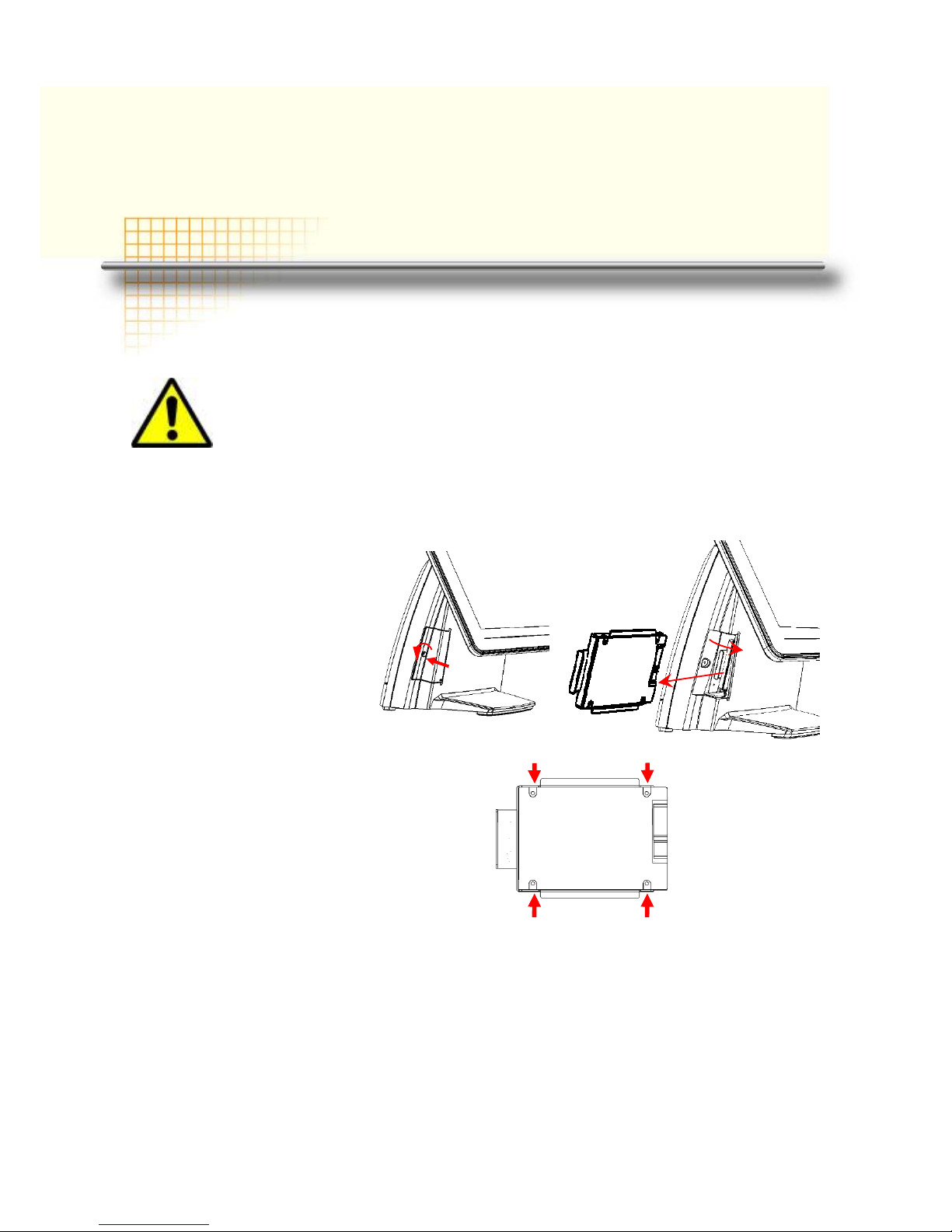
MSR / Finger Print Reciever / RFID / iButton Installation
1. Remove the plastic cover
at the back of Touch
Display Module
2. Insert the MSR / RFID /
Finger Print Receiver / Ibutton Module into USB AType Connector. Fix the
Touch Display Module with
one screw.
3. Make sure the USB connected and screw is fastened well.
4. If you are looking for the detail Utility of MCR, Finger Print Reader, I-button Reader,
RFID Reader, please contact FEC’s FAE.(Please refer to FEC website for more
information, http://www.fecpos.com )
AerPOS Series AP-3617
8
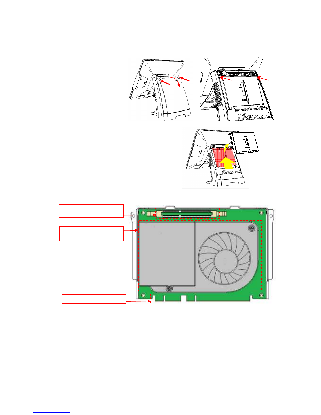
MB / Heatsink & Smart Fan / Memory Installation
1. Remove back cover of the
terminal by two screws on
the top side.
2. Anther two screws at the
both side of MB Module
should be removed for the
further disassembly.
3. Lift up and Pull out the MB
Module from the Terminal
Chassis.
DDR-3 204 Pin
Memory
Smart Fan, Heatsink
CPU & Chipset
Golden Finger

AerPOS Series AP-3617
9
4. During the MB installation,
Please Make sure the MB
Golden finger is well connected
with IO Board Slot.
Memory (DDRIII RAM) & CPU Installation / MB Pin Define,
Battery and Clear CMOS Setting
1. Disassembly the MB Module, then Memory installation can be done from the top side
of MB Module. CPU installation has to remove Thermal Fan Module by 2 screws, after
the CPU installation, please ensure the thermal pads between CPU, chipset and
heatsink are well contacted.
2. According to the MB on-board connectors or golden finger pin define and Battery
Setting, CMOS Clear, please refer to the FH-H611 MB Manual. (Will update soon)
DDR-3 204Pin
Memory Slot
Smart Fan Heatsink
CPU & Chipset
 Loading...