

Page 1
Installation and Operation Manual
FADE Series
Wall Axial Fans
Item #: 401442
Rev Date: 070113
United States
10048 Industrial Blvd., Lenexa, KS, 66215
Tel.: 800.747.1762 • Fax: 800.487.9915
Canada
50 Kanalflakt Way, Bouctouche, NB, E4S 3M5
Tel.: 800.565.3548 • Fax: 877.747.8116
Fantech Inc. certies
that the FADE Series
shown herein is
licensed to bear the
AMCA Seal. The
ratings shown are
based on tests and
procedures performed
in accordance with
AMCA Publication 211
and AMCA Publication
311 and comply with
the requirements of
the AMCA Certied
Ratings Program.
Page 2
2
Note Warning/
Information Technical
Important
note
Read and Save these instructions
for future reference.
1. FADE units can be mounted at any angle for exhaust ventilation.
When planning installation, allow adequate space for blower removal
for service or inspection.
2. Because this unit has rotating parts, safety precautions should be
exercised during all phases of installation, operation and maintenance.
3. CAUTION: “For General Ventilation Use Only. Do Not Use To Exhaust
Hazardous Or Explosive Material and Vapors.”
4. Remove unit from package and inspect within 10 days after receipt. If
damaged, report damage to carrier. Do Not operate this unit with
visible damage to the blower or impeller assembly.
5. Ensure centrifugal impeller has free rotation. If impeller hits orifice,
check screws holding motor bracket. Tighten all screws before
operating unit.
WEAR HAND PROTECTION AND STAY CLEAR OF SHARP EDGES!
6. Screen guards must be installed within reach of personnel, within (7)
feet of the working area, or when advisable for safety.
7. When mounting fan, the inside dimension of the opening should
correspond to dimension “D” possibly allowing an extra 1/4”. When
using a louver or damper, provide adequate framing depth to
accommodate the fan.
PLEASE read the entire manual before installing.
Practical tip
information
WARNINGS
DO NOT CONNECT POWER SUPPLY until fan is completely installed. Make
sure electrical service to the fan is in the locked “OFF” position.
1. All fans are suitable for use with solid-state speed control.
2. WARNING! TO REDUCE THE RISK OF FIRE, ELECTRIC SHOCK, OR
INJURY TO PERSONS - OBSERVE THE FOLLOWING:
a. Use this unit in the manner intended by the manufacturer. If you have
any questions, contact your manufacturer’s representative or contact
us directly.
b. CAUTION: Before installation, servicing or cleaning unit, switch
power off at service panel and lock the service disconnection means
to prevent power from being switched on accidentally. When the
service disconnection means cannot be locked, securely fasten a
prominent warning device, such as tag, to the panel.
c. Installation work and electrical wiring must be done by qualified
person(s) in accordance with all applicable codes and standards,
including fire-rated construction.
d. Sufficient air is needed for proper combustion and exhausting of
gases through the flue (chimney) of fuel burning equipment to
prevent back drafting. Follow the heating equipment manufacturer’s
guideline and safety standards such as those published by the
National Fire Association (NFPA), and the American Society for
Heating, Refrigeration and Air-Conditioning Engineers (ASHRAE), and
the local code authorities.
e. When cutting or drilling into wall and ceiling, do not damage
electrical wiring and other hidden utilities.
f. Ducted fans must always be vented to the outdoors.
g. If this unit is to be installed over a tub or shower, it must be marked
as appropriate for the application and be connected to a GFCI
(Ground Fault Circuit Interrupter) - protected branch circuit.
h. NEVER place a switch where it can be reached from a tub or shower.
3. WARNING! Check voltage at the fan to see if it corresponds to the
motor name plate.
Page 3
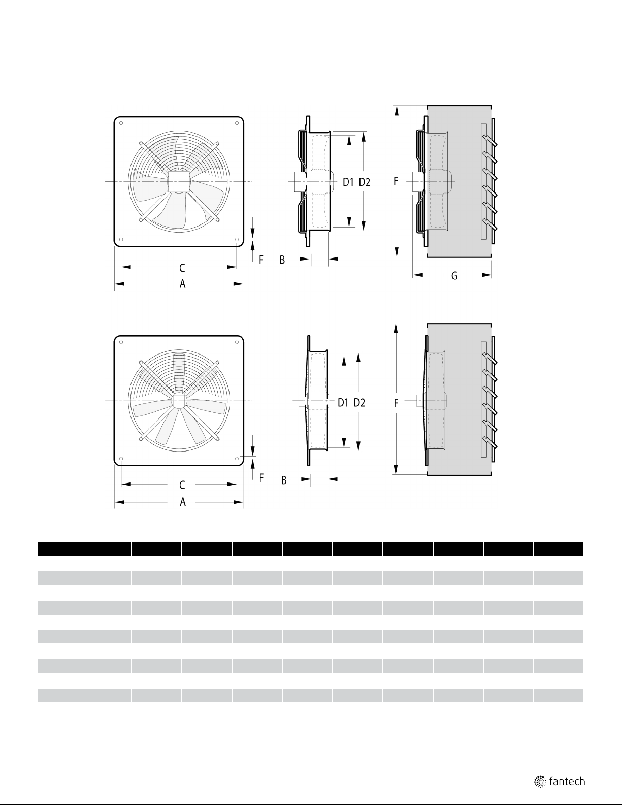
DIMENSIONS
3
FADE S-TYPE
“Fan Only” Model
FADE A-TYPE
“Fan Only” Model
FADE S-TYPE
“Fully Assembled” Model
FADE A-TYPE
“Fully Assembled” Model
Model A B C D1 D2 E F G Blade Type
FADE 8-4 12 5/
FADE 10-4 14 9/
FADE 12-4 / FADE 12-4 WHD 17 3 15 12 12 7/
FADE 14-4 / FADE 14-4 WHD 19 3/
FADE 16-4 / FADE 16-4 WHD 22 3/
FADE 18-4 / FADE 18-4 WHD 22 9/
FADE 20-4 / FADE 20-4 WHD 25 3/
FADE 20-6 / FADE 20-6 WHD 25 3/
FADE 22-6 / FADE 22-6 WHD 28 5/
FADE 25-6 / FADE 24-6 WHD 31 3/
All dimensions in inches. FADE 12 through FADE 25 models can be ordered fully assembled with housing and damper. See Fantech Catalog for detailed descriptions and model numbers.
16
16
16
4
16
16
16
8
4
2 10 1/
2 12 5/
3 1/
8
3 1/
2
4 1/
4
4 1/
2
4 1/
2
5 1/
4
6 29 1/
17 1/
21 16 1/
21 18 18 1/
24 1/
24 1/
26 9/
4
8
8
4
4
16
2
7 3/
4
10 10 5/
14 15 3/
2
20 20 1/
20 20 1/
22 22 1/
25 25 1/
8 1/
17 1/
16
16
8
8
4
2
2
2
2
2
1
/
4
1
/
4
5
/
16
5
/
16
3
/
8
3
/
8
3
/
8
3
/
8
3
/
8
3
/
8
- - S
- - S
21 15 1/
21 15 1/
24 16 1/
24 16 1/
26 17 1/
26 17 1/
32 18 3/
32 18 3/
2
2
2
2
2
2
4
4
S
S
S
S
A
A
A
A
Page 4

4
Motor
Leads
Black
(Ground)
L/L1
N/L2
Supply
Voltage
Blue
Green/Yellow
WIRING
SPECIAL WIRING PRECAUTIONS:
All installation should be wired according to the following diagrams. Failure to comply will cause the motor to "hum" or not work.
All units are pre-wired, just bring incoming supply into marked ports on terminal strip. (EXCEPT FOR 3 PHASE UNITS, please use a motor
contactor & TK leads to prevent damage to motor). Maximum torque that can be applied to the terminal block screws is 0.79 Nm (7
lb-in).
120/230 Volt Single Phase Fans
FADE 8-4
120/230 Volt Single Phase Fans
FADE 18-4, 20-4, 22-6 25-6
Wiring schematic for 4 lead meotors, single phase
1. All leads are color coded as well as identified with an Alpha
/ Alpha or Alpha / Numeric code (i.e. TK or Z2). This code
may be shown as a band on the wire or on a schematic on
the motor hub. Colors should be verified against code band.
If code band and color do not correspond to schematics
above, wire according to the code on the band.
2. Color of capacitor leads may be reversed. Fan operation will
not be affected.
120/230 Volt Single Phase Fans
FADE 10-4, 12-4, 14-4, 16-4
White or
Motor
Leads
Motor
Leads
Brown(TK)
Black (Z1)
Blue (U2)
Green/Yellow
Black (Z1)
White or
Brown(TK)
Blue (U2)
Green/Yellow
Capacitor
Capacitor
L/L1
N/L2
L/L1
N/L2
Supply
Voltage
(Ground)
Supply
Voltage
(Ground)
230 Volt Three Phase Fans
FADE 20-4, 22-6, 25-6
1. Contactor should be used. Control coil should be wired in
series with motor thermal contacts (TK leads) as shown in
diagram to provide thermal motor protection.
2. All leads are color coded as well as identified with a band
containing an Alpha/Alpha or Alpha/Numeric code (i.e. TK or
Z2). Colors should be verified against code band. If code
band and color do not correspond to schematics above,
wire according to the code on the band.
Page 5

Incoming
WIRING (CONT'D)
460 Volt Three Phase Fans
FADE 20-4, 22-6, 25-6
For 460 colt operation, Orange (W2), red (U2) and Grey (V2)
wires must be spliced
1. Contactor should be used. Control coil should be wired in
series with motor thermal contacts (TK leads) as shown in
diagram to provide thermal motor protection
2. All leads are color coded as well as identified with a band
containing an Alpha/Alpha or Alpha/Numeric code (i.e. TK
or Z2). Colors should be verified against code band. If code
band and color do not correspond to schematics above,
wire according to the code on the band.
5
120 Volt Single Phase Fans
FADE 20-6
Black (Z1)
Motor
Leads
White (TK)
Blue (U2)
Green/Yellow
Orange (Z2)
Brown (U1)
White (TK)
Capacitor
L
N
(Ground)
Supply
Voltage
Contactor for 3-Phase Fans, 208-230/460 volt
3-Phase Supply 208/230/460
C1
Control Power
for Contactor
T1 T2 T3
L1
C2
TK TK L1 L2 L3 L3
L2 L3
Motor Leads
AC Contactor
Ground
Page 6

6
WARRANTY
Three (3) Year Warranty
This warranty supersedes all prior warranties
DURING ENTIRE WARRANTY PERIOD:
Fantech will repair or replace any part which has a factory defect in
workmanship or material. Product may need to be returned to the
Fantech factory, together with a copy of the bill of sale and identified
with RMA number.
FOR FACTORY RETURN YOU MUST:
• Have a Return Materials Authorization (RMA) number. This may be
obtained by calling Fantech either in the USA at 1.800.747.1762 or
in CANADA at 1.800.565.3548. Please have bill of sale available.
• The RMA number must be clearly written on the outside of the
carton, or the carton will be refused.
• All parts and/or product will be repaired/replaced and shipped back to
buyer; no credit will be issued.
OR
The Distributor may place an order for the warranty part and/or product
and is invoiced. The Distributor will receive a credit equal to the invoice
only after product is returned prepaid and verified to be defective.
FANTECH WARRANTY TERMS DO NOT PROVIDE FOR REPLACEMENT
WITHOUT CHARGE PRIOR TO INSPECTION FOR A DEFECT.
REPLACEMENTS ISSUED IN ADVANCE OF DEFECT INSPECTION ARE
INVOICED, AND CREDIT IS PENDING INSPECTION OF RETURNED
MATERIAL. DEFECTIVE MATERIAL RETURNED BY END USERS SHOULD
NOT BE REPLACED BY THE DISTRIBUTOR WITHOUT CHARGE TO THE
END USER, AS CREDIT TO DISTRIBUTOR’S ACCOUNT WILL BE
PENDING INSPECTION AND VERIFICATION OF ACTUAL DEFECT BY
FANTECH.
THE FOLLOWING WARRANTIES DO NOT APPLY:
• Damages from shipping, either concealed or visible. Claim must be
filed with freight company.
• Damages resulting from improper wiring or installation.
• Damages or failure caused by acts of God, or resulting from improper
consumer procedures, such as:
1. Improper maintenance
2. Misuse, abuse, abnormal use, or accident, and
3. Incorrect electrical voltage or current.
• Removal or any alteration made on the Fantech label control number
or date of manufacture.
• Any other warranty, expressed, implied or written, and to any
consequential or incidental damages, loss or property, revenues, or
profit, or costs of removal, installation or reinstallation, for any breach
of warranty.
WARRANTY VALIDATION
• The user must keep a copy of the bill of sale to verify purchase date.
• These warranties give you specific legal rights, and are subject to an
applicable consumer protection legislation. You may have additional
rights which vary from state to state.
Limitation of Warranty and Liability
This warranty does not apply to any Fantech product or part which has
failed as a result of faulty installation or abuse, incorrect electrical
connections or alterations made by others, or use under abnormal
operating conditions or misapplication of the product or parts. We will
not approve for payment any repair not made by us or our authorized
agent without prior written consent. The foregoing shall constitute our
sole and exclusive warranty and our sole exclusive liability, and is in lieu
of any other warranties, whether written, oral, implied or statutory.
There are no warranties which extend beyond the description on the
page hereof. In no event, whether as a result of breach of contract, or
Warning
Fantech products are designed and manufactured to provide reliable
performance, but they are not guaranteed to be 100% free from
defects. Even reliable products will experience occasional failures and
this possibility should be recognized by the user. If these products are
warranty or alleged negligence, defect incorrect advice or other causes,
shall Fantech be liable for special or consequential damages, including,
but not limited to, loss of profits or revenue, loss of use of equipment or
any other associated equipment, cost of capital, cost of substitute equipment, facilities or services, downtime costs, or claims of customers of
purchase for such damages. Fantech neither assumes or authorizes any
person to assume for it any other liability in connection with the sale of
product(s) or part(s). Some jurisdictions do not allow the exclusion or
limitation of incidental or consequential damages so the above limitations
and exclusions may not apply to you.
used in a life support ventilation system where failure could result in loss
or injury, the user should provide adequate backup ventilation,
supplementary natural ventilation, failure alarm system, or acknowledge
willingness to accept the risk of such loss or injury.
Page 7

NOTES
7
Page 8

Fantech reserves the right to make technical changes.
For updated documentation please refer to www.fantech.net
Fantech®
 Loading...