

Page 1
1
INSTALLATION, OPERATION AND MAINTENANCE MANUAL
Your ventilation system should be installed in conformance with the appropriate provincial or state
requirements or in the absence of such requirements with the current edition of the National
Building Code, and / or ASHRAE’s “ good Engineering Practice”.
IMPORTANT -
PLEASE READ THIS
MANUAL BEFORE INSTALLING UNIT
CAUTION - Before installation, careful consideration must be given
to how this system will operate if connected to any other piece of
mechanical equipment, i.e. a forced air furnace or air handler, operating at a higher static. After installation, the compatibility of the two
pieces of equipment must be confirmed by measuring the airflow’s of
the Heat / Energy Recovery Ventilators.
It is always important to assess how the operation of any HRV/ERV
may interact with vented combustion equipment (i.e. Gas Furnaces,
Oil Furnaces, Wood Stoves, etc.).
NEVER - install a ventilator in a situation where its normal opera-
tion, lack of operation or partial failure may result in the backdrafting
or improper functioning of vented combustion equipment!!!
Light Commercial
Heat/Energy Recovery Ventilator
C
HRV-XI 450 or ERV-XI 450ERV-WI 500
R
C
R
US
C
Page 2

2
TABLE OF CONTENTS
TECHNICAL DATA
HRV-XI 450 ............................................................................................. 3
ERV-XI 450 ............................................................................................. 5
ERV-WI 500 ............................................................................................. 7
OPERATION
Modes Of Operation ......................................................................................9
Optional Remote Controls............................................................................. 9
INSTALLATION.................................................................................................. 10
Mounting the Unit ....................................................................................... 10
Location & Ducting....................................................................................... 11
Examples .......................................................................................... 14
Air Flow Balancing ...................................................................................... 16
MAINTENANCE ............................................................................................17
ELECTRICAL CONNECTIONS ........................................................................ 18
Limited Warranty
• The HRV-XI 450 heat recovery
polypropylene core has a limited
lifetime warranty.
• The ERV-XI 450 energy recovery
enthalpy core has a limited 5 year
warranty.
• The ERV-WI 500 energy recovery
enthalpy wheel has a limited 1 year
warranty.
• The HRV-XI 450 & ERV-XI 450 has a
warranty that is limited to 5 years on
parts and 7 years on the motor & the
ERV-WI 500 has a warranty that is
limited to 1 year on parts and 7 years
on the motors each from the date of
purchase, including parts replaced
during this time period. If there is no
proof of purchase available, the date
associated with the serial number will
be used for the beginning of the
warranty period.
• The motors found in all Fantech
HRV/ERV’s require no lubrication,
and are factory balanced to prevent
vibration and promote silent
operation.
• The limited warranty covers normal
use. It does not apply to any defects,
malfunctions or failures as a result of
improper installation, abuse,
mishandling, misapplication,
fortuitous occurrence or any other
circumstances outside Fantech’s
control.
• Inappropriate installation or
maintenance may result in the
cancellation of the warranty.
• Any unauthorized work will result in
the cancellation of the warranty.
• Fantech is not responsible for any
incidental or consequential damages
incurred in the use of the ventilation
system.
• Fantech is not responsible for
providing an authorized service
centre near the purchaser or in the
general area.
• Fantech reserves the right to supply
refurbished parts as replacements.
• Transportation, removal and
installation fees are the responsibility
of the purchaser.
• The purchaser is responsible to
adhering to all codes in effect in his
area.
* This warranty is the exclusive and
only warranty in effect relative to the
ventilation system and all other
warranties either expressed or
implied are invalid.
ASHRAE Standard 62-2001 defines acceptable ventilation rates for
various applications.
Outdoor Air Requirements Examples
Application CFM per Person L/s per Person
Coin-operated laundry 15 8
Cafeteria, Fast Food 20 10
Bars 30 15
Conference Room 20 10
Reception Area 15 8
Beauty Shop 25 13
Classroom 15 8
Libraries 15 8
Medical 15 8
Photo Studios 15 8
Living Areas
(residential) .35 air changes per hour but
not less than 15 cfm (7.5 L/s)
per person
Autopsy Rooms – (0.5 cfm/Ft2 or 2.5 L/s m2)
Locker Rooms – (0.5 cfm/Ft2 or 2.5 L/s m2)
* Swimming Pools – (0.5 cfm/Ft2 or 2.5 L/s m2)
Public Restrooms (cfm/wc or cfm/urimac) 50 25
* Call factory for details 1.800.565.548
Page 3
3
POWER & WEIGHT
• Volts 115V Total
• Amperage 7.7 Amps Total
• Weight 140 Lbs
• Shipping Weight 180 Lbs
• Blowers 115V, 60 Hz, 3.85 Amps
• Phase Single Phase
HRV-XI 450
Light Commercial HRV
The HRV-XI 450 Heat Recovery Ventilation system (HRV)
complements the energy efficiency of the modern building by
filtering incoming fresh outdoor air before it enters the heatrecovery core where it is preheated by the outgoing, stale
contaminated air. The HRV then distributes the preheated
fresh filtered air throughout the building by direct ductwork
installed specifically for the HRV or through the ductwork of
a forced-air system.
APPLICATIONS INCLUDE:
• Class Rooms • Offices
• Retail Shops • Clinics
• Hair Salons • Animal Shelters
• Bars & Restaurants • Large Homes
SPECIFICATIONS
CASE 20 gauge galvanized steel. Baked powder coated paint,
grey. Insulated with 1" (25 mm) foil-face fiberglass insulation
to prevent condensation. Two (2) drain connections 1/2"
NPT.
BLOWERS Two ebm™ direct drive external rotor blowers
with forward curved blades. Blowers come with permanently
lubricated sleeves for smooth and quiet operation. Blowers
come pre-wired with 4 speeds, three of which are available
to the installer as standard. Blowers are electrically
connected with a quick connect for quick and easy
inspection of blowers.
CORES Two (2) modular polyproplene heat recovery cores
configured for an efficient cross-flow ventilation. Each core
is 12" x 12" (305 x 305 mm) with a 15" (380 mm) depth.
Cores are manufactured using silicone to withstand extreme
temperature variations. (Aluminum cores are optional.)
FILTERS Four (4) Washable Electrostatic Panel Type Air
Filters, 11.75" (298mm) x 15" (380mm) x 0.25" (6mm)
MOUNTING Unit can be installed using the four (4)
mounting brackets included. Brackets fasten to HRV (bolts
provided) and to floor joists using wood screws, not
provided. Unit may also be suspended by using the supplied
brackets and threaded rod, not supplied, or placed on a
platform.
CONTROLS Low voltage (24VAC) external dry contacts to
activate high speed. External three (3) position switch for
LOW/STAND BY/ MED continuous ventilation speeds.
DEFROST A preset 5 minute defrost sequence is activated at
an outdoor air temperature of 23˚F (-5˚C) and lower. During
the defrost sequence, the supply blower shuts down & the
exhaust blower switches into high speed to maximize the
effectiveness of the defrost strategy. The unit then returns to
normal operation for 25 minutes, and continues cycle.
SERVICEABILITY Cores, filters and drain pans can be
accessed easily from both sides of the HRV from hinged
access panels. Cores conveniently slide out with only 15
"
(380mm) clearance. Blowers can be accessed from both
sides of the HRV from fastened access panels. Blowers are
easily removed by removing the access panel and sliding the
motor plates out of the HRV. A quick connect allows for fast
inspection of blowers.
C
C
US
R
OPTIONAL CONTROLS (WHITE ONLY)
• MDEH 1 – Mechanical Low Voltage Dehumidistat
• FD 15M – 15 Minutes Crank Timer
• AQS 1 – Air Quality Sensor
* External dry contacts (provided)
Heat Recovery Ventilator
FOR MORE INFORMATION CONTACT:
Page 4

4
Unit:
Date:
Contractor:
Project:
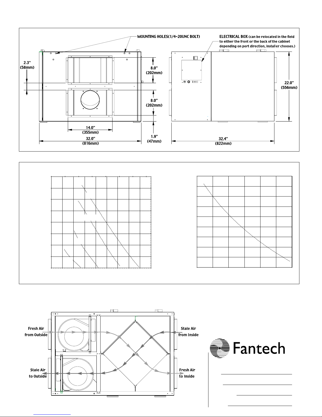
Dimensions
Airflow
HRV-XI 450 Light Commercial HRV
2.3"
(58mm)
0 35 71 106 142 177 212 248 283
2
1.8
1.6
1.4
1.2
14.0"
(355mm)
32.0"
(816mm)
Airflow (L/s)
High
* Med-High
MOUNTING HOLES(1/4-20UNC BOLT)
8.0"
(202mm)
8.0"
(202mm)
DRAIN CONNECTION 1/2 NPT
1.9"
(47mm)
497.6
447.8
398.1
348.3
298.6
0.75
0.7
0.65
ELECTRICAL BOX
to either the front or the back of the cabinet
depending on port direction installer chooses)
(can be relocated in the field
22.0"
(556mm)
32.4"
(822mm)
1
0.8
0.6
0.4
Static Pressure (in WC)
0.2
0
0 50 100 150 200 250 300 350 400 450 500
Med
Low
Airflow (cfm)
* Med-High - Contact
Factory for wiring info
248.8
199.0
149.3
Static Pressure (Pa)
99.5
49.8
0.0
0.6
Efficiency (%)
0.55
0.5
0.45
150 200 250 300 350 400 450 500
Airflow (cfm)
Page 5
FOR MORE INFORMATION CONTACT:
POWER & WEIGHT
• Volts 115V Total
• Amperage 7.7 Amps Total
• Weight 140 Lbs
• Shipping Weight 180 Lbs
• Blowers 115V, 60 Hz, 3.85 Amps
• Phase Single Phase
ERV-XI 450
Light Commercial ERV
The ERV-XI 450 lowers demand on air conditioning systems.
Air supplied from outdoors enters through the Energy
Recovery Core where it transfers the heat and humidity to the
exhaust air . The air supplied by the ERV-XI 450 is now cooler,
dryer and more comfortable. The ERV-XI 450 distributes the
pre-conditioned fresh filtered air throughout the building by
direct ductwork installed specifically for the ERV or through
the ductwork of a forced-air system.
APPLICATIONS INCLUDE:
• Class Rooms • Offices
• Retail Shops • Clinics
• Hair Salons • Animal Shelters
• Bars & Restaurants • Larger Homes
SPECIFICATIONS
CASE 20 gauge galvanized steel. Baked powder coated paint,
grey. Insulated with 1" (25 mm) foil-face fiberglass insulation
to prevent condensation.
BLOWERS Two ebm™ direct drive external rotor blowers
with forward curved blades. Blowers come with permanently
lubricated sleeves for smooth, quiet operation. Blowers
come pre-wired with 4 speeds, three of which are available
to the installer as standard. Blowers are electrically
connected with a quick connect for fast and easy inspection
of blowers.
CORES Two (2) modular enthalpic energy recovery cores
configured for an efficient cross-flow ventilation. Each core
is 12" x 12" (305 x 305 mm) with a 15" (380 mm) depth.
FILTERS Four (4) Washable Electrostatic Panel Type Air
Filters, 11.75" (298mm) x 15" (380mm) x 0.25" (6mm)
MOUNTING Unit can be installed using the four (4)
mounting brackets included. Brackets fasten to ERV (bolts
provided) and to floor joists using wood screws, not
provided. Unit may also be suspended by using the supplied
brackets and threaded rod, not supplied, or placed on a
platform.
CONTROLS Low voltage (24VAC) external dry contacts to
activate high speed. External three (3) position switch for
LOW/STAND BY/ MED continuous ventilation speeds.
SERVICEABILITY Cores and filters can be accessed easily
from both sides of the ERV from hinged access panels.
Cores conveniently slide out with only 15"(380mm)
clearance. Blowers can be accessed from both sides of the
ERV from fastened access panels. Blowers are easily
removed by removing the access panel and sliding the
motor plates out of the ERV. A quick connect allows for fast
inspection of blowers.
C
C
US
R
OPTIONAL CONTROLS (WHITE ONLY)
• FD 15M – 15 Minute Crank Timer
• AQS 1 – Air Quality Sensor
• MDEH – Dehumidistat
(read full description of
control found under "optional remote
control" in this manual)
Energy Recovery Ventilator
5
Page 6
6
Dimensions
Airflow
ERV-XI 450 Light Commercial ERV
Unit:
Date:
Contractor:
Project:
Airflow (L/s)
24 59 94 130 165 201 236 271
1.6
398.1
0.85
1.4
1.2
1
0.8
0.6
0.4
Static Pressure (in W.C.)
0.2
0
50 100 150 200 250 300 350 400 450 500
Low
High
* Med-High
Med
Airflow (cfm)
* Med-High - Contact
Factory for wiring info
348.3
298.6
248.8
199.0
149.3
99.5
Static Pressure (Pa)
49.8
0.0
0.83
0.81
0.79
0.77
0.75
Efficiency (%)
0.73
0.71
0.69
0.67
150 200 250 300 350 400 450
Airflow (cfm)
Page 7

7
POWER & WEIGHT
• Volts 115V Total
• Amperage 8.2 Amps Total
• Weight 300 Lbs
• Shipping Weight 340 Lbs
• Blowers 115V, 60 Hz, 3.85 Amps
• Phase Single Phase
ERV-WI 500
Light Commercial ERV
The ERV-WI 500 is an energy recovery ventilator (ERV) that
transfers both latent and heat energy. Designed for most
cliamates and especially for hot humid regions, the ERV -WI
500 is an effective balanced ventilator that reduces energy
costs. Air drawn in from outside enters through the ERV
wheel where it is conditioned by the seperated exhause air
stream.
APPLICATIONS INCLUDE:
• Class Rooms • Offices
• Retail Shops • Clinics
• Hair Salons • Larger Homes
• Bars & Restaurants
SPECIFICATIONS
CASE 20 gauge galvanized steel. Baked powder coated paint,
grey. Insulated with 1" (25 mm) foil-face fiberglass insulation
to prevent condensation.
BLOWERS Two ebm™ direct drive external rotor blowers
with backward curved blades. Blowers come with
permanently lubricated bearings for smooth, quiet operation.
Blowers come pre-wired with 1 speed, but can be
individually slowed down with optional speed control.
Blowers are electrically connected with a quick connect for
quick and easy inspection of blowers.
FILTERS Two (2) 2" medium efficiency pleated filters, one (1)
per air stream.
MOUNTING Unit may be suspended by using the supplied
brackets and threaded rod, not supplied, or placed on a
platform.
CONTROLS Low voltage (24VAC) internal dry contacts to
activate unit from off position to high speed, see wiring
diagram.
DEFROST A preset 5 minute defrost sequence is activated at
an outdoor air temperature of 23˚F (-5˚C) and lower. During
the defrost sequence, the supply blower shuts down. The
unit then returns to normal operation for 25 minutes, and
continues cycle, until temperature rises above set point.
SERVICEABILITY Wheel and filters slide out without tools.
Access door is secured with safety screw.
ENTHALPY WHEEL
• Homogenous media; Not coated or bonded;
Will not delaminate
• Synthetic wheel is completely corrosion resistant
• Unitary wheel media construction maximizes face flatness
and fluted geometry to minimize cross-contamination
• 4-Å molecular sieve desiccant allows only water molecules
to be transferred; Minimal cross-contamination
• Wheel is completely water washable
• Maintenance-free bearings
• Full contact brush seals
• Certified to 1060 Rating Air to Air Energy Recovery
Equipment
OPTIONAL CONTROLS
• FD 15M – 15 Minute Crank Timer
• High-voltage 120 V Speed Controller for blowers
– Can be hard wired to remote location
* ERV unit is shipped from factory set on high speed
• MDEH – Dehumidistat (read full description of
control found under "optional remote
control" in this manual.)
• Other controls not available through Fantech may
be used if compatible with this unit, see controls.
Energy Recovery Ventilator
FOR MORE INFORMATION CONTACT:
R
Page 8

8
ERV-WI 500 Light Commercial ERV
Dimensions
(25.70")
654mm
(14")
355mm
(8")
203mm
(17.67")
449mm
(5.90")
149mm
(54.30")
1379mm
(56.30")
1429mm
(50.23")
1276mm
(32.16")
817mm
(30.40")
772mm
(18.32")
465.4mm
(3.24")
82mm
Airflow
Unit:
Date:
Contractor:
Project:
Airflow (L/s)
Static Pressure (in W.C.)
High Speed
Low Speed
Airflow (cfm)
Static Pressure (Pa)
Page 9

9
Air Quality Sensor – AQS 1(Not compatible with ERV-WI 500)
The wall mount Air Quality Sensor (AQS) monitors
indoor air quality and activates the override mode when
cigarette smoke, formaldehyde, benzene, volatile
organic compounds and other pollutants are detected.
The unit will then return to normal mode once the air
pollutants are reduced to a pre-determined lower level.
Three low voltage wires are required for operation
* This control is not a warning device.
Dehumidistat – MDEH 1
The wall mount dehumidistat monitors the humidity level
in the area it is installed. When the humidity level rises
above the desired set-point, the HRV will activate to high
speed/override mode. Once the humidity level returns to
desired condition, the unit will return to the normal mode.
Two (2) low voltage wires required for operation.
Note the
dehumidistat helps dehumidify by increasing the speed of the
HRV/ERV. Dehumidification will only take place when the air outside is
dryer than the air inside.
OPTIONAL REMOTE CONTROLS
1. Continuous / Ventilation Mode
In this mode of operation both fans are operating and exchanging air with the outside. The heat/energy recovery ventilator (HRV/ERV) constantly exchanges the air at the rate you select, either at low or medium speed, and switches to
high speed when activated by an optional remote control. The "Low" and "Med" fan speed selection will cause the unit
to operate in continuous exchange mode at a reduce exchange rate. Continuous mode is recommended, since pollutants are slowly but constantly being generated in a building.
NOTE: Model ERV-WI 500 is a single speed unit only. Optional speed control is available.
2. Intermittent / Standby Mode
The system is always on standby and operates at high speed when activated by an optional remote control
(required): "Standby" should be selected if the user wishes to stop the unit from continuous exchange.
3. Defrost (Fan shutdown HRV -XI 450 & ERV -WI 500 only)
The automatic defrost cycle of HRV’s consists of a fan shutdown. When the supply air stream temperature goes below
23°F (-5°C), the supply motor shuts down and the exhaust
motor goes in to high speed. Ambient air is passed through
the unit for a period of 5 minutes. The supply motor will then
re-start and run at the preset speed. The exhaust motor will
also slow down to the preset speed, and the unit will operate
in the run cycle for 25 minutes. This fan shutdown defrost
cycle continues until the supply air stream rises above 23°F
(-5°C).
MODES OF OPERATION
OPERATION
The HRV/ERV is shipped from the factory on low speed, intermittent operation can be obtain by toggle switch located
on outside of cabinet (HRV -XI 450 & ER V-XI 450) or by manipulating jumpers in the electrical box. See wiring diagram.
The ERV-WI 500 is factory set to high speed. Internal low voltage contacts allow interuption of power to unit when
optional remote control is used. See spec sheet for control options.
SETTING SPEED
HRV-XI 450
ERV-XI 450
Example
Dry Contacts
* HRV-XI 450 Shown
*
Page 10

10
• Install the unit close to the
outside wall on which the
supply and exhaust hoods
will be mounted.
• Have a nearby power
supply 120 Volts, 60 Hz.
• Have the possibility of
mounting the unit to
supporting beams.
• Mount the unit as level as
possible in order to allow
proper condensate
drainage. Failure to do so
may void warranty.
(HRV-XI 450 only)
• Have access to a water
drain for the condensate of
the unit during defrost.
(HRV-XI 450)
• The HRV-XI or ERV-XI
can be accessed for regular
maintenance by both sides
using one of the two
latched doors. Leave
appropriate clearance.
INSTALLATION
PRACTICAL
TIPS
Installing Drain Line (HRV-XI 450 only)
Through normal operation and including defrost mode, the HRV-XI 450 may produce some condensation. This water should flow into a nearby drain, or be taken
away by a condensate pump. The HRV and all condensate lines must be installed in
a space where the temperature is maintained above the freezing point. A“P” trap
should be made in the drain line. This will prevent odors from being drawn back up
into the unit. The drain connection is a 1/2" NPT nipple.
MOUNTING
LOCATION
The HRV/ERV must be located in a heated space where it will be possible to conveniently service the unit. Typically the HRV/ERV would be located in the mechanical
room, above a drop ceiling or an area close to the outside wall where the weatherhoods will be mounted. Attic installations are not normally recommended due to
extreme temperatures, and difficulty in performing, required service & maintenance.
If an attic is slected, special care should be taken in ensuring the unit will perform
as intended. Unit may need to be protected with insulated shelter, built on site.
Connecting appliances to the HRV/ERV It is not recommended, including:
- clothes dryer
- kitchen exhaust hoods
- combustion venting
- central vacuum system
These appliance may cause lint, dust or grease to collect in the HRV , damaging
the unit.
NOTE: Connecting any of these type of appliances to the HRV will invalidate your
warranty
Install the drain hose, making a “P” trap
Page 11

11
INSTALLING DUCTS GOING TO / FROM OUTSIDE
INSTALLING THE DUCTING TO THE WEATHERHOODS
OUTSIDE WEATHERHOODS – The weatherhoods must have built-in "bird" screens with 1/4 inch (6.35 mm)
minimum mesh to prevent birds and rodents from entering into the ductwork. Do not use smaller mesh as it will be very
susceptible to pluging up. The preferred location of the weatherhoods is:
• no less than 10 ft. (3 m) apart from each other.
• at least 18 inches (457.2 mm) snow line or ground level.
• supply hood must be kept away from source of cantaminants, such as automobile exhaust fumes, gas
meters, garbage cans, containers, cooling towers, tar roofs, etc.
• avoid prevailing winds, whenever reasonably possible.
The outside perimeter of the weatherhood must be sealed to prevent leakage into the building.
The design and size of the weatherhoods or louvers chosen by the installer must allow for adequate free area. Water
and snow penetration of the system is minimized when the airflow does not exceed 1000 FPM (5.08 m/s) free area
velocity.
DUCTING FROM THE WEATHERHOODS–TO AND FROM THE HRV/ERV – Insulated galvanized
sheet metal ducting with sufficient cross section with an integral single piece vapor barier should be used to connect
the HRV/ERV to the weatherhoods. Insulated flex duct may be used in moderation, if sized and installed properly.
(Consult local codes)
A minimum R value of insulation should be equal to 4 (RSI 0.75) ,consult local codes.
All ducts should be sealed using a good bead of high quality caulking (preferably acoustical sealant) and a high quality
aluminum foil tape, or other approved duct sealant.
Page 12

12
PRACTICAL
TIPS
INSTALLING DUCTS TO / FROM INSIDE
• The fresh air inlet from
the HRV needs to ensure
proper air mixing and
temperature in the air
handler. Units should be
interlocked with one
another so that the air
handler runs, when there
is a call for ventilation.
• Units may be operating at
different static pressures.
Compatibility of the two
(2) systems must be verified by checking that balance of the HRV/ERV
found in this manual.
Notes: See air handler
manufacturer for
appropriate
specifications.
Direct Connection to Furnace/ Air handler return duct
• Should you wish to hard duct the supply air directly into the cold air return of the
HVAC systems, remember to check the airflow balance of the HRV with the HVAC
systems fan both “on”and “off” to determine that it does not imbalance the HRV
more than 10%. Make sure you respect the minimum distance from the supply air
in of the HRV/ERV and the HVAC systems (Refer to your local and National
Building & Heating Codes for any variations in these notes).
• It may be necessary to install a separate fresh air supply ductwork system if the
heating is other than forced air.
When installing an HRV/ERV, the designer and installer should be aware of local
codes that may require smoke detectors and/or firestats in the HVAC or HRV/ERV
ductwork.
Because an HRV/ERV is designed to bring fresh air into the building, structures
may require supply voltage interrupt when smoke or flame sensors are triggered,
or when a central fire alarm system is activated.
* See installation examples found in this manual.
To maximize airflow in the ductwork system, all ducts should be kept short and have as few bends or elbows as possible. Forty-five degree are preferred to 90˚ elbows. Use “Y” tees instead of 90˚ elbows whenever possible.
All duct joints must be fastened with screws or duct sealant and wrapped with a quality duct tape to prevent leakage.
Aluminum foil duct tape is recommended.
SUPPLY AIR DUCTING
In buildings without a forced air HVAC systems, fresh air should be supplied to all habitable areas. It should be supplied from high wall or ceiling locations. Grilles that diffuse the air comfortably such as Fantech grille {MGE (metal)
or PGE (plastic)}s are recommended.To avoid possible noise transfer through the ductwork system, a piece of flexible ducting should be connected between the HRV and the supply ductwork system.
If the floor is the only option available, then special care should be taken in locating grilles. Areas such as under
baseboard heaters will help to temper the air. Also optional inline duct heaters are available for mounting in the supply duct work to add heat if required.In buildings with a forced air HVAC systems, you may want to connect the HRV
to the HVAC ductwork (see information below).
Page 13

13
• Choose the location your
Supply and Exhaust
Fantech grille {MGE
(metal) or PGE (plastic)}s.
The Exhaust Grilles
should be located in
areas where known
contaminant's exist.
• A piece of flexible
ducting should be placed
between the HRV and
the rigid ducting to
absorb any noise or
vibrations.
• The grilles should be
installed on the ceiling or
on high the wall 6” (152
mm) to 12” (305 mm)
from the ceiling.
Push the Fantech grille {MGE (metal) or PGE (plastic)} into the optional mounting
collar or directly into installed elbow.
INSTALLING DUCTS TO / FROM INSIDE (CON’T)
PRACTICAL
TIPS
Exhaust Air ducting
The stale air exhaust system is used to draw air from the points in the building where the worst air quality problems
occur. ( See installation examples in the manual.)
Backdraft Dampers
Backdraft dampers may be desired to prevent the passive migration of unwanted outside air when the HRV/ERV is
set to standby or off mode.
Page 14

INSTALLATION EXAMPLES
* Drawings are illustrations only and actual port locations and airflow directions may vary,
consult unit spec sheets.
It is the responsibility of the installer to ensure all ductwork is sized and installed as designed to ensure the system
will perform as intended. The amount of air (CFM) that an HRV/ERV will deliver is directly related to the total external static pressure (E.S.P.) of the system. Static pressure is a measure of resistance imposed on the blower by
length of duct work/number of fittings used in duct work, duct heater etc.
Fully Dedicated System
• Stale air drawn from areas of contamination
• Fresh air supplied to main areas
• HRV/ERV must be balanced
• External heating or cooling coil may be needed if air is not able to mix confortably.
Partially Dedicated System (Direct Connection)
• Stale air drawn from areas of contamination
• Fresh air supplied to return of air handler
• Air Handler blower may need to operate when call for ventilation
• HRV/ERV must be balanced
BALANCING DAMPERS
SUPPLY IN
EXHAUST OUT
HRV UNIT
SUPPLY IN
RETURN AIR DUCT
AIR HANDLER UNIT
SUPPLY DUCT
SUPPLY IN
EXHAUST OUT
HRV UNIT
BALANCING DAMPERS
SUPPLY IN
EXHAUST AIR TO HRV UNIT
Page 15

INSTALLATION EXAMPLES (CON'T)
* Drawings are illustrations only and actual port locations and airflow directions may vary,
consult unit spec sheets.
It is the responsibility of the installer to ensure all ductwork is sized and installed as designed to ensure the system
will perform as intended. The amount of air (CFM) that an HRV will deliver is directly related to the total external static pressure (E.S.P.) of the system. Static pressure is a measure of resistance imposed on the blower by length of
duct work/number of fittings used in duct work, duct heater etc.
Simplified Installation
• Stale air drawn from return of air handler
• Fresh air supplied to return of air handler, further down
stream of HRV/ERV exhaust
• Air Handler blower must operate when HRV/ERV is providing
ventilation
• HRV/ERV must be balanced
Partially Dedicated System (Indirect Connections)
• Stale areas drawn from areas of contamination
• Fresh air supplied into ceiling return air plenum or grille
• HRV/ERV must be balanced
12" BREATHER SPACE
AIR HANDLER UNIT
CEILING RETURN AIR PLENUM
BALANCING DAMPERS
SUPPLY IN
EXHAUST OUT
HRV UNIT
EXHAUST AIR TO HRV UNIT
SUPPLY IN
SUPPLY DUCT
AIR HANDLER UNIT
SUPPLY IN
EXHAUST OUT
HRV UNIT
RETURN AIR DUCT
BALANCING DAMPERS
SUPPLY IN
Page 16

16
PITOT TUBE BALANCING PROCEDURE
PITOT TUBE
BALANCING PROCEDURE
The following is a method of field balancing an HRV/ERV
using a Pitot tube, advantageous in situations when flow
stations are not installed in the ductwork. Procedure
should be performed with the HRV/ERV on high speed.
The first step is to operate all mechanical systems on high
speed, which have an influence on the ventilation system,
i.e. the HRV/ERV itself and the forced air HVAC system or
air handler if applicable. This will provide the maximum
pressure that the HRV/ERV will need to overcome, and
allow for a more accurate balance of the unit.
Drill a small hole in the duct (about 3/16"), four feet downstream of any elbows or bends, and two feet upstream of
any elbows or bends.
These are recommended distances but the actual installation may limit the amount of straight duct.
The Pitot tube should be connected to a magnehelic gauge
or other manometer capable of reading from 0 to 0.25 in (062 Pa) of water, preferably to 3 digits of resolution. The
tube coming out of the top of the pitot is connected to the
high pressure side of the gauge. The tube coming out of
the side of the pitot is connected to the low pressure or reference side of the gauge.
Insert the Pitot tube into the duct; pointing the tip into the
airflow. For general balancing it is sufficient to move the
pitot tube around in the duct and take an average or typical reading. Repeat this procedure in the other (supply
or return) duct. Determine which duct has the highest
airflow (highest reading on the gauge). Then damper
that airflow back to match the lower reading from the
other duct. The flows should now be balanced. Actual
airflow can be determined from the gauge reading. The
value read on the gauge is called the velocity pressure.
The Pitot tube comes with a chart that will give the air
flow velocity based on the velocity pressure indicated by
the gauge. This velocity will be in either feet per minute
or meters per second. To determine the actual airflow,
the velocity is multiplied by the cross sectional areas of
the duct being measured.
The accuracy of the air flow reading will be affected by
how close to any elbows or bends the readings are
taken. Accuracy can be increased by taking an average
of multiple readings as outlined in the literature supplied
with the Pitot tube.
A The duct’s airflow
velocity is measured
with a magnehelic
gauge and a pitot
tube. See “Pitot Tube
Balancing
Procedure” next
page.
• To avoid airflow
turbulence and
incorrect readings,
the airflow velocity
should be measured
on steel ducting a
minimum of 3 duct
cross-section from
the unit or elbow and
before any transition.
• The balancing procedure consists of measuring the exhaust air leaving the system
and the supply air entering the system and ensuring that these two are equal. A
deviation of 10% or less is acceptable. In such cases, it is recommended to have a
greater amount of exhaust air than supply air as so to increase the supply air’s
temperature.
AIR FLOW BALANCING
PRACTICAL
TIPS
• If the unit’s airflows are
not properly balanced...
- The unit may not operate
at it’s maximum
efficiency.
- Heat & Energy recovery
core damage may occur.
- The unit’s use could
cause negative or
positive pressure in the
building causing cold air
to enter or other
combustible equipment
to backdraft.
- The unit may not
defrost properly.
A*
Pitot tube and gauge
Air
Flow
M
Duct
Pitot
Tube
Magnehelic
c
i
l
e
h
e
n
g
a
Gauge
Page 17

17
MAINTENANCE
The filters need to be checked and cleaned once a month or when they appear dirty.
PRACTICAL
TIPS
• To prevent electrical
shock, check that the
unit is unplugged
before doing any
repairs or maintenance.
• A yearly inspection is
recommended to
ensure the efficiency
and trouble-free use of
your system. Run
through the system
and verify the different
operating modes.
FILTERS
The motor - The motors
are factory balanced and
lubricated for life. They
require no maintenance.
The unit - The inside of
the unit should be vacuumed yearly. Be careful
not to damage any of the
mechanical components
and electrical connections.
Condensation Panel The condensation panel
should be cleaned yearly
or as needed.
The drain and drain line Units with drain hoses
should have their line and
connection checked regularly.
Outside hoods - The outside hoods need to be
checked every season to
make sure there are no
leaves or insects blocking
the airflow. Check regularly that there are no pollutants near the intake
hood. Make sure they are
clear of any snow accumulation during the winter
months.
Clean core on a average every 3-6 months.
a) Open access door & remove filters.
b) Carefully grip ends of core and pull evenly outward. Core may be snug, but
will slide out of the channel.
c) Vacuum only ERV-XI 450 core (do not wash).
d) Wash HRV-XI 450 core in warm soapy water.
e) Install clean core
f) Install the clean filters
g) Replace access door
Note: Core installation label on the outer end of the core.
To install the clean Core and Filters.
a) first mount the bottom flange of the core guide into the bottom channel approximately 1/4” (6mm)
b) mount the left or right side flange of the core guide approximately 1/4 “ (6mm) followed by the other side
c) mount the top flange of the core guide into the top channel approximately 1/4” (6mm)
d) with all four corners in place and the core straight and even, push hard in the centre of the core until the core
stops on the back of the cabinet.
CAUTION MAKE SURE UNIT IS UNPLUGGED BEFORE ATTEMPTING ANY MAINTENANCE WORK
The following components should also be inspected regularly and well maintained.
FIXED PLATE HRV-XI 450 (Polypropylene Core) Wash OK & ERV-XI 450 (Enthalpy Core) Vacuum Only
WHEEL ERV-WI 500 (Enthalpic Wheel) Wash OK
Seals – The seals are designed to be durable and require no
maintenance other than adjustment, but if seals become worn
or damaged they may easily be replaced. The seals are made
to clip on the cassette or post metal easily.
Wheel – The wheel is somewhat self cleaning through its normal action of rotating in and out of countercurrent airflow
streams.. If the wheel becomes dirty, it may be cleaned by
blowing out the unit with compressed air (20 psig maximum).
In cases of severe uncleanliness, the wheel may be removed
from the cassette and washed with water following wheel
removable procedures outlined below:
1. Open ERV-WI 500 access door so that the front or back of the cassette may be easily
accessed.
2. Support the wheel from the bottom
3. If the unit is equipped with an internal bearing, unbolt the shaft screw on both sides of
the shaft. Unbolt one post completely and remove post. Remove the shaft clips at the
face of the hub from both sides of the shaft. Remove the shaft. Roll the wheel out carefully.
4. With the wheel out, wash the media carefully with water. Once clean, allow the media
to dry out for several hours or days if necessary.
5. Reinstall using the reverse procedure. Run the unit. It may take several hours for the
desiccant to dry out and for the wheel to perform normally.
Page 18

18
WIRING DIAGRAM HRV-XI 450
WIRING DIAGRAM ERV-XI 450
POWER CORD
120 VAC
FU
LIVE
GROUND
TB1
120VAC
REMOTE
CONTROL
TB1
TB1
2
1
24VAC
24VAC FOR AQS
TB4-TB6
TB4-TB6
R1
(EXHAUST)
1
NC
5
6 (Green)
Red
White
COM
TB8-TB10
3
2
NO
4
EXHAUST
TB8-TB10
Red
White
TB3
5 (Blue)
Blue
1 (White)
2 (Red)
3 (Grey)
4 (Black)
(SUPPLY)
1
NC
5
TB1
R2
3
COM
2
NO
TB7
4
Black
Red
TB6
Defrost
Timer
TB10
TB5
TB4
TB3
TB9
TB8
TB7
R3
(DEFROST)
1
NC
5
1 (White)
2 (Red)
3 (Grey)
4 (Black)
3
COM
2
NO
4
White
Yellow
Black
SUPPLY
5 (Blue)
TB3
CLIX-ON or
THERMISTOR
6 (Green)
R4
3
COM
21
NO
NC
5
4
NEUTRAL
TB2
TB2
TB1 TB1
REMOTE
CONTROL
TB1
TB1
2
1
24VAC
120VAC
POWER CORD
120 VAC
LIVE
FU
GROUND
R1
(EXHAUST)
1
NC
5
TB4-TB6
Red
White
TB4-TB6
COM
NO
TB8-TB10
3
2
4
TB8-TB10
Red
White
TB2
R2
(SUPPLY)
3
COM
21
TB3
NC
5
NO
TB7
4
24VAC FOR AQS
NEUTRAL
TB2
6 (Green)
EXHAUST
5 (Blue)
TB2
1 (White)
2 (Red)
3 (Grey)
4 (Black)
TB6
TB5
TB4
TB3
TB10
TB9
TB8
TB7
1 (White)
2 (Red)
3 (Grey)
4 (Black)
SUPPLY
5 (Blue)
TB2
6 (Green)
Page 19

19
WIRING DIAGRAM ERV-WI 500
POWER CORD
120 VAC
FU
LINE
GROUND
TB1
TB5 & TB6 Internal low voltage
contacts for remote control option
TB6
TB5
24 VAC
Brown
TB3
TB7
R1
3
2
5
4
R2
3
11
5
2
4
R3
4
1
8
5
12
9
14
13
TB9
TB8
SPEED CONTROL
(OPTIONAL)
TB10
SPEED CONTROL
(OPTIONAL)
MOTOR
WHEEL
Brown
NEUTRAL
TB2
MOTOR
EXHAUST
TB4
Blue
Black
MOTOR
SUPPLY
TB4
Black
Blue
Page 20

Article #: 301025
Rev Date: 021203
Manufactured by:
United States
1712 Northgate Blvd. • Sarasota, Fl. USA 34234
(T) 1.800.747.1762 • (F) 1.800.487.9915
(T) 1.941.309.6000 • (F) 1.941.309.6099
Ontario & Western Canada
10-6665 Tomken Road
Mississauga, Ontario
Canada L5T 2C4
(T) 1.800.407.6195 • (F) 1.800.407.8965
(T) 1.905.696.9235 • (F) 1.905.696.9236
Québec & Atlantic Provinces
50 Kanalflakt Way • Bouctouche, NB, Canada E4S
3M5
(T) 1.800.565.3548 • (F) 1.877.747.8116
(T) 1.506.743.9500 • (F) 1.506.743.9600
www.fantech.net
info@fantech.net
Technical support hotline 1.800.565.3548
ISO 9001
 Loading...