

Fantech EPD150LR, EPD180CR, EPD190LR, EPD250CR Installation And Maintenance Manual

fantech
Installation and Maintenance Manual
Industrial Dehumidifier
Déshumidificateur industriel
Deshumidificador industrial
Read and Save
These
Instructions
Lisez et
conservez ces
instructions
Lea y guarde
estas
instrucciones
Manual de Instalación y Mantenimiento
EPD Series
Industrial Dehumidier
Deshumidicador industrial
Item #: 405037
Rev Date: 2015-06-01
EPD150LR • EPD180CR • EPD190LR • EPD250CR
United States
10048 Industrial Blvd., Lenexa, KS, 66215
Tel.: 800.747.1762 • Fax: 800.487.9915
Canada
50 Kanalflakt Way, Bouctouche, NB, E4S 3M5
Tel.: 800.565.3548 • Fax: 877.747.8116

2
Note Warning/
Information Technical
Important
note
WARNINGS
Plug into a grounded 3 prong outlet
Do not remove ground prong.
Do not use and adapter.
Do not use an extension cord.
Failure to follow these instructions can result in death, fire, or electrical
shock
WARNING: The dehumidifier uses a high pressure refrigerant system and
high voltage circuitry which could present a health hazard resulting in
death, serious bodily injury, and/or property damage. Only qualified service people should service this unit.
Practical tip
information
ADVERTENCIAS
Conecte a un contacto de pared de conexión a tierra de 3 terminales.
No quite la terminal de conexión a tierra.
No use un adaptador.
No use un cable elétrico de extensión.
No seguir estas instrucciones puede ocasional la muerte, incendio o choque
eléctrico.
ADVERTENCIA: El deshumidificador utiliza un sistema de líquido refrigerante de alta presión y un circuito eléctrico de alto voltaje que podrían
resultar en daños materiales, peligro para la salud, lesiones corporales
graves, e incluso la muerte. Sólo personal cualificado debe dar servicio a
esta unidad.
CAUTION: Do not operate unit without the front hood secured in place.
The serial data plate is located on the underside of the dehumidifier. For
service information contact 1-800-565-3548.
PRECAUCIÓN: No utilice la unidad hasta haber asegurado la cubierta frontal en posición cerrada.
La placa serial está situada en el superficie inferior del deshumidificador.
Consulte con el número 1-800-565-3548 para másinformación sobre
servicio.
fantech

Industrial Dehumidifier
Pump Purge Button (Fig. 2)
In normal operation, the pump will automat-
ically empty the reservoir. Pressing this but-
ton allows manual emptying of the reservoir.
Press once, and the pump will operate for
20 seconds. Press and hold the button and
the pump will activate for 30 seconds.
Always manually purge the water reservoir
before transport or storage. Turn off the
power and allow the plugged in dehumidifier
to rest 5 minutes before the final purge.
Fig. 2
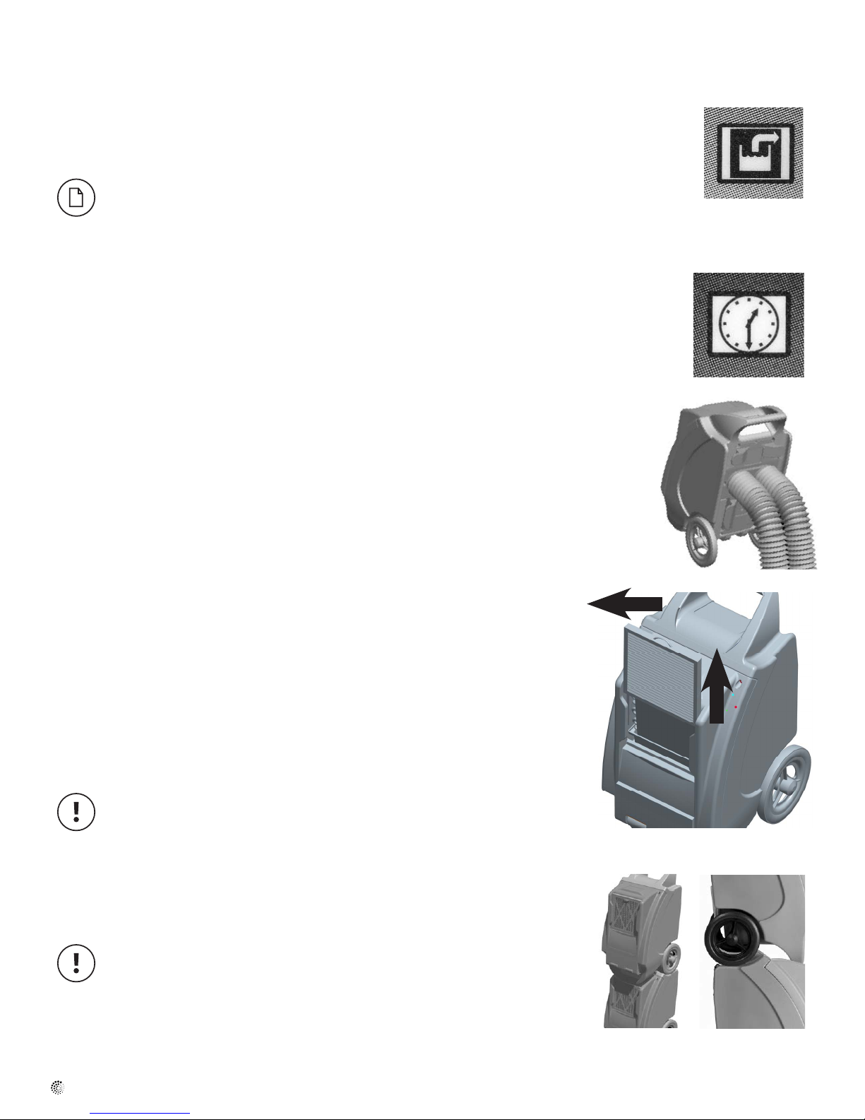
Digital Hour Counter (Fig. 3)
The counter will accumulate and display the total running hours
of the unit in 1/10 of an hour.
Hour Button (Fig. 4)
Press the HOURS button when the dehu-
midifier cannot be plugged in and the hour
meter needs to be read. The digital hour
meter will display the last saved cumulative
time for ten seconds.
Defrost Indicator (Fig. 5)
The defrost indicator will light to indicate the
dehumidifier is in defrost cycle. During this
Defrost Cycle
When ice builds up on the coils, a thermistor activates the elec-
tronic control and defrost light. The compressor is turned off by
the thermistor temperature measurement. The blower will contin-
ue to run, causing air to flow through the evaporator coil and melt
the ice. When the ice is melted, the thermistor will end the defrost
cycle and the compressor will be started.
Disconnect dehumidifier from power supply. The hour meter uses
a battery backup for display when the dehumidifier is unplugged
and the hour button is depressed. To change the battery, it is nec-
essary to remove the four (4) screws from the control panel.
Disconnect the old battery and replace with new battery. Replace
control panel and screws. Do not overtighten screws.
Fig. 3
Fig. 4
Electrical Shock Hazard
Plug into a grounded 3 prong outlet.
Do not remove ground prong.
Do not use an adapter.
WARNING
Disconnect power supply before replacing battery.
Failure to follow these instructions can result in death,
fire, or electrical shock.
Battery Replacement
Fig. 2
Fig. 4
Electrical Requirements
For 115V operation, a common grounded outlet on a 15 amp circuit is required. If used in a wet area, a ground fault interrupter (GFI) is required.
Built in Electrical Safety
For your safety and protection this appliance is manufactured with a grounded plug on its power cord. The power cord must be plugged into a properly
grounded receptacle. If a grounded receptacle does not exist, have one installed by a certified electrician. Do not cut or remove the grounding prong
on the power cord plug if equipped. We recommend that this electrical circuit/receptacle operate under a separate breaker or fuse.
If an extension cord is required, it must have a minimum of 14 gauge conductors if 25 feet long or less and 12 gauge conductors if greater than 25
feet long.
3
Limitations of Use
Temperature: 4°C to 35°C (40°F to 95°F)
Relative Humidity: 20 to 80%
Water Removal
The dehumidifier is equipped with an internal condensate pump to remove the water that is collected from the air. This allows the water to be pumped
20 feet with the attached hose. If the water needs to be pumped more than 20 feet above the unit, a second pump must be added to relay the water.
The condensate pump automatically purges for 20 seconds every four minutes.
Operation
Place dehumidifier inside area to be dried. Make sure all windows and doors are closed to the
outside and seal off the wet area from any unaffected areas. Route condensate hose into a drain, or
a very large container. Press the On/Off button (figure 1) to activate the dehumidifier.
Start-up Mode
The dehumidifier is turned on or off by pressing the power button (figure 1). When the dehumidifier
is started, the hour meter will briefly display the software version #, followed by the cumulative
hours.
Pressing the power button during the first minute, the unit will go into OFF Mode immediately.
Run Mode
During Run Mode the compressor is running causing the evaporator to get cold resulting in
condensate forming on the coil.
The unit will stay in run mode for variable length of time depending on the ambient conditions.
Pressing the power button (figure 1) will send the unit in shut down mode (see below)
Figure 1
Figure 2
Defrost Mode
During the defrost mode, the indicator light will turn on (figure 2), the compressor will be off and the fan
will continue to run. The pump purge will be activated automatically.
The defrost cycle runs every 45 minutes in cool ambient temperature, less often in warm ambient
temperature and the length of time in defrost will vary appropriately.
Heavy frosting on the coil can be expected during low ambient conditions and will not affect the
operation of the unit.
fantech
4
Fig. 8
Shut Down Mode
Pressing the power button after the first minute of operation will initiate a shut-down mode. This mode
will last 15 minutes and will maintain the operation of the fan and purge pump to insure all water is
removed from the unit prior to moving or storing. Pressing the power button at any time during the shut
down mode will immediately shut down the unit and bypass the remainder of the shutdown mode. The
unit must be purged by pressing the purge button if bypassing the shutdown mode to avoid water
overflow.
The display will change during shutdown mode to a countdown timer that will indicate the
time remaining before the unit shuts completely off.
Functions
Loss of Power Recovery Function
In case of a loss of power, the last run state (ON or OFF) will be maintained when the power is
restored.
Pump Purge Function
In normal operation, the pump will automatically empty the reservoir. Pressing the purge button
(figure 3) runs the pump for 1 minute allowing manual emptying of the reservoir. The pump purge
will function in all modes as long as the unit is plugged in.
Hour Meter Display
The cumulative hours will be displayed during normal operation. If the unit is off (even unplugged)
pressing the hour button (figure 4) will also display the accumulative hours briefly.
Venting / Ducting
Twin rear outlets (figure 5) can accommodate two individual 5” ducts or one 10” lay flat duct to be
attached. This allows for warm dry air to be directed into different areas.
Figure 3
Figure 4
Figure 5
Maintenance
Air Filter
The air filter should be checked regularly. Operating the dehumidifier with a clogged filter will reduce
efficiency. To access the filter, slide the filter frame up until it clears the dehumidifier cabinet
(figure 6). Reverse procedure to re-install the filter into the dehumidifier. Metal filters should be
washed with soap and water, and paper filters should be replaced.
Paper filter size is a nominal 12" x 12" x 1"
Operating the unit without the filter in place will cause reduced efficiency due to dirty coils and
increase the frequency of internal coil cleaning.
Stacking
The dehumidifiers can be stacked on top of each other (figure 7). The wheels from the upper unit
must be resting in the cradle of the lower unit. DO NOT STACK MORE THAN TWO HIGH.
Battery Replacement
Disconnect power supply before replacing battery.
Failure to follow these instructions can result in death, fire, or electrical shock
Disconnect dehumidifier from power supply. The hour meter uses a battery backup for display when the
dehumidifier is unplugged and the hour button is depressed. To change the battery, it is necessary to remove
the four (4) screws from the control panel. Disconnect the old battery and replace with new battery.
Replace control panel and screws. Do not overtighten screws.
Figure 6
Figure 7
fantech

Fig. 8
Cleaning
Disconnect power supply before cleaning
Failure to follow these instructions can result in death, fire, or electrical shock
External Cleaning
Use a non-flammable mild, non-abrasive soap and water solution. Wipe dry.
Internal Cleaning
Disconnect dehumidifier from power supply.
Light cleaning: Remove the air filter and spray evaporator coil with water.
Heavy cleaning: Remove two upper screws from front hood. Open hood. Spray water at coils. Close
hood and replace screws. (figure 8)
Care must be taken to insure coil fins are not damaged, as damaged fins can restrict airflow
and reduce the unit's ability to produce water.
Storage
Freezing temperatures and biological growth must be considered before storing the dehumidifier. To
prevent the biological growth, spray an evaporator cleaner on the coils and rinse into the drainage
system. You must also purge the excess liquid from the pump using the manual purge function to
prevent issues with freezing storage environments.
5
Figure 8
Troubleshooting
Service
A qualified refrigeration technician must service all refrigerant leaks.
The Unit is NOT working:
• Has the breaker tripped? – Reset breaker
• If in a wet area, is the unit plugged into a GFI protected circuit? – Excessive
moisture will trip GFI. Remove from area.
• Is the unit being run off a generator? - Check output does not fluctuate
as the unit will not operate at low voltage.
• If using an extension cord - Is the cord of the correct gauge for the
distance run? (14 AWG up to 25’ and 12 AWG over 25’). Note: Verify
voltage while unit is starting. Start up will cause the highest current draw
and largest voltage drop. Even if plugged directly to outlet there can be
a significant voltage drop. Never assume the voltage is ok without
verifying.
The unit shuts down and displays an error code.
ER 1: Overflow switch remaining closed for >2 minutes.
• Plugged or kinked drain hose – Remove obstruction
• Bad connection in pump circuit – Check connections
• Defective condensate pump – Replace
ER 2: Internal pressure switch indicates refrigerant pressure is too high.
• Air filter is dirty or plugged – Clean or replace air filter
• The coil is dirty – Clean the coil
• Loose or faulty electrical connections to pressure switch – check
connections
• Fan is not working – Replace
• Defective pressure switch – replace
The unit continually ices up: Note that some ice buildup on the evaporator coil
is normal but airflow should not be blocked.
• Is warm air blowing out the back of the unit? - No warm air, ambient
temperature may be too low. Raise temperature with supplementary
source.
• Is the air filter clean and airflow unobstructed? – Clean filter. Unit should
have a minimum of 10” clearance all around it.
• Dirty evaporator coil? – Clean coil.
Unit moves some water but not as much as expected:
• Air filter dirty or airflow obstructed - Unit should have a minimum of 10”
clearance all around it. Clean air filter and ensure adequate airflow/space
around unit.
• Evaporator coil dirty – Clean coil.
• Restrictive or kinked exhaust ducting (if used) – Straighten out ducting.
Fan does not run. Compressor runs briefly but cycles on/off:
• Loose connection in fan circuit – Check connections.
• Fan obstructed and not turning – Remove obstruction.
• Defective fan – Replace fan.
• Defective control board – Replace control board.
fantech
 Loading...