

Fantech DBF110 User Manual

fantech
Installation and Operation Manual
Manuel d'installation et d'opération
Manual de Instalación y Mantenimiento
DBF110
Dryer Booster Fans
Amplicateur de séchoir
Booster Secadora
DBF110 Kit Includes:
Dryer Booster Fan, 1 pc
Fan Mounting Bracket and Hardware, 1 pc
Small Wall Sign Indicating Proper Operation
Procedure, 1 pc
Item #: 401441
Rev Date: 042514
La trousse du DBF110 inclus:
Ventilateur en ligne, 1 pc
Support de montage pour le ventilateur avec
quincaillerie,1 pc
Petit panneau indiquand la bonne procédure
d'opération, 1 pc
El DBF110 incluye:
Ventilador de Refuerzo de la Secadora, 1 pc
Soporte de Montaje y Herrajes del Ventilador, 1 pc
Letrero Pequeño de Pared que Indica el
Procedimiento Adecuado de Operación, 1 pc
United States
10048 Industrial Blvd., Lenexa, KS, 66215
Tel.: 800.747.1762 • Fax: 800.487.9915
Canada
50 Kanalflakt Way, Bouctouche, NB, E4S 3M5
Tel.: 800.565.3548 • Fax: 877.747.8116
2
Note Warning /
Read and Save these instructions for
future reference.
1. DBF 110 fans are not explosion proof. Do
not use the fans if a potentially explosive
situation may exist.
2. Because this unit has rotating parts, safety
precautions should be exercised during this
phase of installation, operation and
maintenance.
3. CAUTION: For General Ventilation Use Only.
Do Not Use To Exhaust Hazardous Or Explosive
Material and Vapors.
4. The fan motor, capacitor and pressure
switch connections are pre-wired from the
factory.
Information Technical
Important
information
note
Veillez à lire et conserver ces
instructions pour leur consultation
future
1. Veuillez noter que les ventilateurs DBF110
à monter sur conduits d’évacuation ne sont pas
à l’épreuve des explosions. Ne pas utiliser les
ventilateurs dans des situations potentiellement
explosives.
2. Étant donné ses parties amovibles,
certaines précautions doivent être prises lors
de l’installation, l’opération et l’entretien.
3. ATTENTION: “Pour usage de ventilation
générale seulement.Ne pas utiliser pour
l’évacuation de matériaux et de vapeurs
dangereux ou explosifs.”
4. Veuillez noter que les raccords du moteur
du ventilateur, du condensateur et du rupteur
de pression ont été câblés à l’avance en usine.
Practical tip
Lea y guarde estas instrucciones para
referencia futura
1. Los ventiladores DBF 110 no son a prueba de
explosión. No utilice los ventiladores si existiera
la posibilidad potencial de que se produjera una
explosión.
2. Debido a que esta unidad tiene piezas
rotativas, hay que tomar precauciones de
seguridad durante la instalación, operación y
mantenimiento.
3. PRECAUCION: “Sólo para Ventilación en
General. No trate de Utilizarse como Extractor
de materiales y Vapores Peligrosos o Explosivos.”
4. El motor, el capacitor y el interruptor de
presión del ventilador vienen cableados de
fábrica.
fantech
3
WARNINGS
DO NOT CONNECT POWER SUPPLY UNTIL FAN IS
COMPLETELY INSTALLED. MAKE SURE ELECTRICAL
SERVICE TO THE FAN IS LOCKED IN "OFF" POSITION.
1. TO REDUCE THE RISK OF FIRE, ELECTRIC
SHOCK, OR INJURY TO PERSONS - OBSERVE
THE FOLLOWING:
a. Use this unit only in the manner intended by
the manufacturer. If you have questions,
contact the factory.
b. Before servicing or cleaning, switch power off
at service panel and lock service panel to
prevent fan from being switched on
accidentally. When the service disconnecting
means cannot be locked, securely fasten a
prominent warning device, such as a tag, to
the service panel.
c. Installation work and electrical wiring must
be done by qualified person(s) in accordance
with all applicable codes and standards,
including fire-rated construction.
d. The combustion airflow needed for safe
operation of fuel burning equipment may be
affected by this unit's operation. Follow the
heating equipment manufacturer's guidelines
and safety standards such as those
published by the National Fire Protection
Association (NFPA), the American Society of
Heating, Refrigeration, and Air Conditioning
Engineers (ASHRAE) and the local code
authorities.
e. When cutting or drilling into wall or ceiling,
do not damage electrical wires or other
hidden utilities.
f. Ducted fans must always be vented to the
outdoors.
g. Install the fan a minimum of 5 linear feet
from the dryer outlet.
2. WARNING! Check voltage at the fan to see if
it corresponds to the motor nameplate.
3. DO NOT USE with heated air in excess 140F
(60C).
ADVERTISSEMENTS
NE BRANCHEZ PAS LE COURANT AVANT D’AVOIR
ENTIÈREMENT TERMINÉ L’INSTALLATION DU
VENTILATEUR. S’ASSUREZ QUE L’ALIMENTATION
ÉLECTRIQUE DU VENTILATEUR EST VERROUILLÉE EN
POSITION “OFF” (ARRÊT).
1. AVERTISSEMENTS POUR RÉDUIRE LES
RISQUES D’INCENDIE, DE DECHARGE
ELECTRIQUE OU RISQUE DE BLESSURES. SUIVEZ
LES CONSEILS SUIVANTS:
a. N’utilisez ce dispositif que de la manière
préconisée par le fabricant. Pour toutes
questions, veuillez contacter l’usine de
fabrication.
b. Avant tout entretien ou nettoyage, coupez le
courant au tableau électrique et verrouillez ce
dernier pour empêcher l’activation
accidentelle du ventilateur. Quand le système
de coupure de courant ne peut pas être
verrouillé, attachez solidement sur le tableau
électrique, un dispositif de signalisation bien
en vue, tel qu’une étiquette.
c. Les travaux d’installation et de branchement
électrique doivent être faits par un personnel
qualifié et conformément aux dispositions de
tous les codes et normes de construction en
vigueur, y compris celles de prévention des
incendies.
d. Une ventilation suffisante à la bonne
combustion et évacuation des gaz par le
conduit (la cheminée) des équipements
fonctionnant au carburant est nécessaire de
façon à empêcher les refoulements. Suivez
les instructions données et les normes de
sécurité communiquées par le fabricant,
telles que celles publiées par l’Association
nationale de protection contre les incendies
(National Faire Protection Association
[NFPA]), l’Association américaine des
ingénieurs en chauffage, réfrigération et
climatisation (American Society of Heating,
Refrigeration, and Air Conditioning [ASHRAE])
et les autorités localement en charge de la
construction.
e. Lors du perçage ou du découpage d’un mur
ou d’un plafond, prenez garde de ne pas
endommager les fils électriques ou autres
conduits s’y trouvant dissimulés.
f. Les ventilateurs installés sur les conduits
doivent toujours être ventilés vers l’extérieur.
g. Installez le ventilateur à ua moins 1,55m
(5 pi.) linéaires à partir de la sortie du
ventilateur.
2. ATTENTION : Vérifier le voltage afin de voir s’il
correspond à celui indiqué sur la plaque du
moteur.
ADVERTENCIAS
NO CONECTE LA CORRIENTE HASTA TANTO EL
VENTILADOR QUEDE COMPLETAMENTE INSTALADO.
TENGA CUIDADO DE QUE LA ALIMENTACION
ELECTRICA DEL VENTILADOR QUEDE ASEGURADA EN
LA POSICION “OFF” (DESCONECTADA).
1. ADVERTENCIA: PARA REDUCIR EL RIESGO DE
INCENDIO, CONMOCION ELECTRICA O LESIONES
A PERSONAS, OBSERVE LO SIGUIENTE:
a. Sólo utilice esta unidad de la manera
prescrita por el fabricante. Si tiene cualquier
pregunta, favor consultar a la fábrica.
b. Antes del mantenimiento o limpieza,
desconecte la alimentación en el tablero de
control y ciérrelo con llave para impedir la
activación accidental del ventilador. En caso
de no poder cerrarse con llave el dispositivo
de desconexión, fije firmemente al tablero de
control un dispositivo prominente de
advertencia, por ejemplo, una etiqueta.
c. La labor de instalación y cableado eléctrico
debe ser realizada por personal calificado,
acorde a todas las normas del caso incluso
construcción calificada para incendios.
d. Hace falta aire suficiente para la debida
combustión y extracción de gases a través
de la chimenea de quemadores de
combustible, a fin de impedir el contratiro.
Siga las directrices del fabricante de los
equipos de calefacción y normas de
seguridad tales como las publicadas por la
National FireProtection Association (NFPA Asociación Nacional de Protección Contra
Incendios), la American Society of Heating,
Refrigeration and Air Conditioning Engineers
(ASHRAE -Asociación Americana de
Ingenieros de Calefacción, Refrigeración y
Aire Acondicionado), y porlas autoridades
competentes de la localidad.
e. Al perforar o cortar paredes o techos, evite
dañar cables eléctricos u otros servicios
empotrados.
f. Los ventiladores instalados en conductos
siempre deben ventilarse al exterior.
g. Instale el ventilador con un minimo de
distancia de 5 pies lineales de la salida del
secador.
4. ADVERTENCIA: Compruebe el voltaje de
entrada al ventilador para constatar que
corresponda al voltaje de placa del motor.
3. NO UTILICE con aire calendo en el axceso 140F
(60C).
3. N’EMPLOYEZ PAS si que l’air est supérieur a
140F (60C).
fantech
4
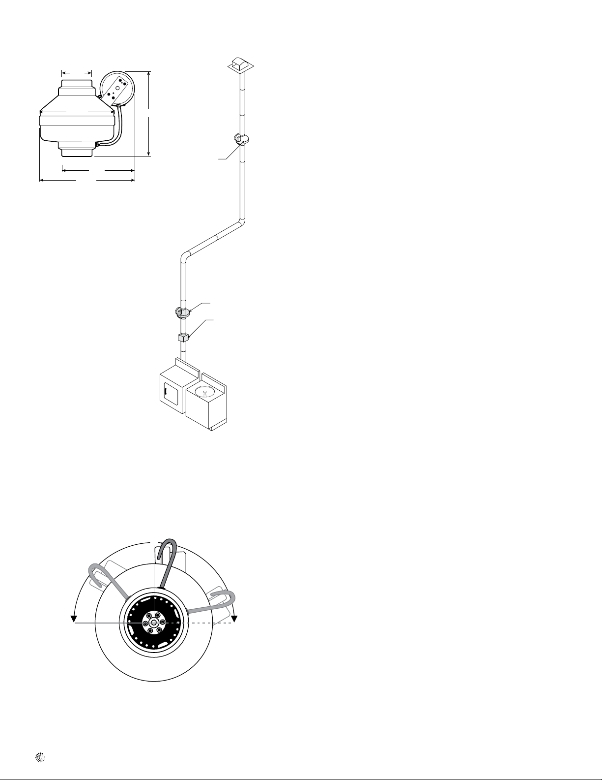
121/2”
111/4”
91/2”
91/2”
37/8”
Dimensional Data
Dimensions are in inches.
12-o-clock
Illustration 1
DBF110
Alternative Location
Secondary Lint Trap
Installation Guidelines
Fan and Switch Mounting
The DBF110 is to be mounted a minimum of 5 linear (not equivalent) feet
from the dryer outlet. A secondary lint trap (DBLT 4W) is recommended
if the fan is installed between 5 and 15 linear (not equivalent) feet from
the dryer outlet in applications, where excessive dryer lint generation is
likely or to increase the time interval between routine maintenance of the
Dryer Booster Fan (See illustration to left). An NB mounting bracket
attached to a rafter or joist should be used to stabilize the fan. Although
not recommended, a vertical rigid duct may support the fan if the duct is
securely stabilized. (Consult local codes prior to supporting the fan in the
duct alone.) Duct work should be attached to the inlet and outlet of the
fan by means of FC vibration isolation clamps (not included) or duct tape.
The duct connection should be properly sealed to prevent leakage and
loss of fan performance. Flex duct connections between the dryer duct
connection and exhaust duct should be stretched as smooth as possible.
Calculating Duct Run
To calculate the length of your planned duct run, measure from the dryer
to external venting point in roof or wall. For each bend or elbow add 5-7
feet to your total duct run calculations. The DBF110 can be used on runs
up to 108 feet.
Pressure Sensor Switch Operation
Fantech’s DBF110 is equipped with Fantech's Patented DB10 pressure
switch. The DB10 is a positive pressure sensing switch which
recognizes dryer operation and activates the booster fan from an
independent electrical circuit. This eliminates connections through the
dryer circuit which may void the manufacturers’ warranty as well as
manual systems which require the attention of the operator or costly
current/temperature sensing systems.
The electricity to the booster fan is connected in series through a
normally open terminal on the switch. A pressure tap is connected to a
fitting on the side of the switch. When the dryer begins operation,
positive pressure in the duct causes the switch diaphragm to expand,
closing the circuit to the booster fan. An integral delay-on-break timer in
the switch will cycle the fan on for intervals of 10 minutes. This will continue until the dryer has stopped and the timer delay period has lapsed.
Drying cycles, the booster fan, the delay timer and the pressure switch
are not adversely affected by the starting/stopping intervals.
fantech
10-o-clock
2-o-clock
Sensitivity Adjustment Instruction
a. Disconnect power to the booster fan.
b. Looking from the inlet (dryer side), the switch should be at the
12-o-clock position.
c. Remove the 2 mounting screws holding the switch to the fan.
d. Rotate the switch to the 10-o-clock position for less sensitivity or
2-o-clock position for more sensitivity then secure it there, you may
have to adjust (bend) the bracket to fit. Secure the switch with the
2 screws previously removed.
e. Apply power to the fan and check for operation.
5
Fan Installation
Step 1. Selecting Fan Location
Fan must be mounted a minimum of 15 feet from the dryer outlet.
In order to perform recommended maintenance, fan location should allow
sufficient access for service. Refer to dimensional drawings shown above.
Step 2. Mount Bracket
Using the wood screws provided, attach the mounting bracket to a support
beam at the selected location. Bracket is provided with grommets in order
to isolate any vibration and prevent the transmission of sound through the
structure. Be careful not to overtighten. Fan mounting can be in any angle
(see ill. 2), however, vertical mounting is recommended to reduce
condensation buildup in the fan. If a horizontal installation is necessary and
condensation buildup may pose a problem, a ¼" hole drilled in the bottom
of the housing (along with an NPT insert [by others] and drain tubing) may
be installed to allow condensation to drain.
Step 3. Mount Fan
For proper operation, the switch diaphragm must be positioned vertically.
(Illustrations below show diaphragm position for horizontal, vertical and
ducts installed at an angle.) Wiring box should be positioned for easy
access. Attach fan to the mounting bracket with the self tapping screws
provided. Care should be taken not to strip the plastic housing. Although
screw pilot holes are not required, 3/32" (or smaller) pilot holes are
recommended.
Illustration 2
Correct Mounting of Diaphragm Switch
Horizontal Vertical Angled
Switch mounted
properly
above and
below
Switch mounted
properly above
duct.
Incorrect Mounting of Diaphragm Switch
duct.
Illustration 3
Steps 2 & 3 may be reversed.
Attach Mounting Bracket to
stud using screws provided.
Illustration 4
Switch Circuit
Attach Fan to Mounting
Bracket using screws provided.
Electrical Supply from
Breaker Panel
fantech
 Loading...