

Page 1
CVS Model
fantech
Inline Multi-Port Ventilators
Item #: 402332
Rev Date: 2015-05-12
Installation Manual
United States
10048 Industrial Blvd., Lenexa, KS, 66215
Tel.: 800.747.1762 • Fax: 800.487.9915
Canada
50 Kanalflakt Way, Bouctouche, NB, E4S 3M5
Tel.: 800.565.3548 • Fax: 877.747.8116
Page 2
2
Note Warning /
Information Technical
Important
note
READ THESE INSTRUCTIONS COMPLETELY BEFORE INSTALLING FAN AND
SAVE THESE INSTRUCTIONS FOR FUTURE REFERENCE.
TO REDUCE THE RISK OF FIRE, ELECTRIC SHOCK, OR INJURY TO PERSONS,
OBSERVE THE FOLLOWING:
• Use this unit only in the manner intended by the manufacturer. If you
have questions, contact the manufacturer.
• Before Servicing or Cleaning Unit, Switch Power Off At Service Panel
and Lock Service Panel To Prevent Power From Being Switched On
Accidentally.
• Installation Work And Electrical Wiring Must Be Done By Qualified
Person(s) In Accordance With All Applicable Codes And Standards,
Including Fire-Rated Construction.
• The combustion airflow needed for safe operation of fuel-burning
equipment may be affected by this unit’s operation. Follow the heating
equipment manufacturer’s guideline and safety standards such as
those published by the National Fire Protection Association (NFPA),
and the American Society for Heating, Refrigeration and Air
Conditioning Engineers (ASHRAE), and the local code authorities.
Practical tip
information
• When cutting or drilling into walls or ceilings, do not damage electrical
wiring and other hidden utilities.
• Ducted fans must always be vented to the outdoors.
• If this unit is to be installed over a tub or shower, it must be marked
as appropriate for the application.
• NEVER place a switch where it can be reached from a tub or shower.
• FOR INTERIOR USE ONLY
• DO NOT USE WITH HEATED AIR IN EXCESS OF 60°C (140°F).
• CAUTION: For General Ventilation Use Only. Do Not Use To Exhaust
Hazardous Or Explosive Materials And Vapors.
fantech
Page 3
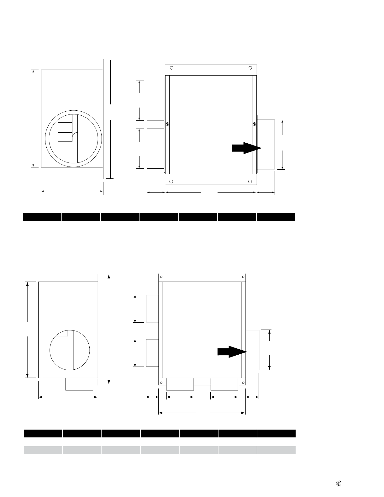
Dimensions
C
4
F
3
A2
A1
DF
D
A1
A1
A2
A2
Air ow
1
2 1/
/
2
4
E
E
Model A1 A2 C D E F
CVS275A 6 5 11 15 7
Dimensional information is in inches
A2
A2
D
F
F
D
A2
A2
4
C
C
3
/
4
Air ow
12
2 1/
2
1
4
/
4
A1
A1
3
/
1
E
E
1 3/
4
4
A1
A2
A2A2
C
Model A1 A2 C D E F
CVS300A 6 4 13 18
CVS400A 6 4 13 18
Dimensional information is in inches
3
/
4
3
/
4
1
8
/
4
1
8
/
4
3
/
1
1 3/
4
16
16
fantech
Page 4

4
Installation
Installing the Mounting Casing and Fan
STEP 1.
When selecting a fan mounting location, the following criteria should be
considered: a) type of application; b) service accessibility; and c) mounting to minimize noise generated by fan operation.
a) Intermittent ventilation - i.e. bathroom exhaust, kitchen area
exhaust; continuous ventilation for indoor air quality. Important
Notice: When using the fan in a continuous system, adequate
makeup air should be provided in order to prevent backdrafting of
combustion appliances.
b) Fan location should allow sufficient access for service.
c) Mounting the fan as far as possible from the exhaust point will
minimize fan operating noise from being transmitted back through
the duct work. If the fan is to be used as a booster for moving the
air between two rooms, a central point along the duct may be optimal. Insulated type duct work (recommended for all bathroom
exhaust applications) will also result in quieter operation.
STEP 2.
To fasten the mounting casing to the ceiling, use either threaded rod or
wires to suspend the unit from the ceiling. You may also install the unit
by fastening it to a frame using either wood or sheet-metal screws
depending on the surface to which you chose to attach the unit. The
frame should be designed to eliminate vibration.
STEP 3.
Connect duct work to inlet and outlet of fan using FC clamps or duct
tape. When using insulated duct, it is recommended that the inner vinyl
core be clamped or taped to the inlet and outlet collar and that the
vapor barrier surrounding the insulation be duct taped to the side of the
unit.
Installing the Supply/Exhaust Grill
STEP 1.
Select the grill mounting point within the area to be ventilated. To ease
installation, locations of framing beams within the walls or joists supporting the ceiling should be considered.
STEP 2.
Place the mounting collar in the selected location and trace a circle onto
the surface. From the interior side of the room, cut through the surface.
Please note: in order to assure a smoother finish when mounting
through a sheetrock or tile type ceiling, it is recommended that a razor
knife be used to make the cut.
STEP 3.
From within the attic or crawl space, place the ducting into the hole
until the edge of the duct is flush with the interior wall or ceiling surface. Attach collar to the duct work and clamp or tape into place, if necessary. If grills are equipped with mounting screws, install them before
installing the duct work.
STEP 4.
Insert grill.
Multi-Port Ventilation System – Residential Application
Vent #1
Duct
Duct
Back-draft Damper
Grill
Vent #2
Fantech CVS
Series Fan
Louvered
Exhaust
Outlet
We recommend the use
of exible duct
fantech
Page 5

Electrical Connections
5
Do not connect power supply until fan is completely installed.
Make sure electrical service to the fan is locked in “OFF”
position.
STEP 1.
Punch out the knockout on the same side as where the female plugin cover is located. Note that it is possible to place the plug-in on the
other side of the unit by simply removing the screw securing the cover
and installing it on the other side where a pre-drilled hole is provided.
Remember to also move the grounding screw to the same side as the
female plug.
STEP 2.
Run the two lead wires through the knockout. Connect the electrical
power source (see wiring diagram). Use wire connectors-insulators to
join each lead wire to the power source. Fasten the ground wire from the
electrical source to the screw provided (indicated by the ground symbol
).
If the motor assembly is already installed and plugged into the
female plug-in, skip step 3 and 4.
STEP 3.
Insert the motor assembly into the square hole so that the mounting
holes align. Hint: Insert one side of the motor assembly and slide it so
that the fan is partially under the motorplate, then insert the other side.
Fasten with four (4) sheet metal screws, included.
STEP 4.
Before starting the unit, turn the fan by hand to assure a free rotation.
If it hits the orice, check the screws holding the motor bracket.
Adjustments can be made by loosening the motor bracket screws.
STEP 5.
Plug in the motor assembly to the female plug-in.
STEP 6.
Place the cover on top of the unit and fasten with the two (2) sheet metal
screws provided.
fantech
Page 6

6
Notes
fantech
Page 7

Warranty
Five (5) Year Warranty
This warranty supersedes all prior warranties
7
DURING ENTIRE WARRANTY PERIOD:
Fantech will repair or replace any part which has a factory defect in
workmanship or material. Product may need to be returned to the
Fantech factory, together with a copy of the bill of sale and identified
with RMA number.
FOR FACTORY RETURN YOU MUST:
• Have a Return Materials Authorization (RMA) number. This may be
obtained by calling Fantech either in the USA at 1.800.747.1762 or
in CANADA at 1.800.565.3548. Please have bill of sale available.
• The RMA number must be clearly written on the outside of the carton, or the carton will be refused.
• All parts and/or product will be repaired/replaced and shipped back to
buyer; no credit will be issued.
OR
The Distributor may place an order for the warranty part and/or product
and is invoiced. The Distributor will receive a credit equal to the invoice
only after product is returned prepaid and verified to be defective.
FANTECH WARRANTY TERMS DO NOT PROVIDE FOR REPLACEMENT
WITHOUT CHARGE PRIOR TO INSPECTION FOR A DEFECT.
REPLACEMENTS ISSUED IN ADVANCE OF DEFECT INSPECTION ARE
INVOICED, AND CREDIT IS PENDING INSPECTION OF RETURNED
MATERIAL. DEFECTIVE MATERIAL RETURNED BY END USERS SHOULD
NOT BE REPLACED BY THE DISTRIBUTOR WITHOUT CHARGE TO THE
END USER, AS CREDIT TO DISTRIBUTOR’S ACCOUNT WILL BE
PENDING INSPECTION AND VERIFICATION OF ACTUAL DEFECT BY
FANTECH.
THE FOLLOWING WARRANTIES DO NOT APPLY:
• Damages from shipping, either concealed or visible. Claim must be
filed with freight company.
• Damages resulting from improper wiring or installation.
• Damages or failure caused by acts of God, or resulting from improper
consumer procedures, such as:
1. Improper maintenance
2. Misuse, abuse, abnormal use, or accident, and
3. Incorrect electrical voltage or current.
• Removal or any alteration made on the Fantech label control number
or date of manufacture.
• Any other warranty, expressed, implied or written, and to any consequential or incidental damages, loss or property, revenues, or profit,
or costs of removal, installation or reinstallation, for any breach of
warranty.
WARRANTY VALIDATION
• The user must keep a copy of the bill of sale to verify purchase date.
• These warranties give you specific legal rights, and are subject to an
applicable consumer protection legislation. You may have additional
rights which vary from state to state.
Limitation of Warranty and Liability
This warranty does not apply to any Fantech product or part which has
failed as a result of faulty installation or abuse, incorrect electrical connections or alterations made by others, or use under abnormal operating
conditions or misapplication of the product or parts. We will not approve
for payment any repair not made by us or our authorized agent without
prior written consent. The foregoing shall constitute our sole and exclusive warranty and our sole exclusive liability, and is in lieu of any other
warranties, whether written, oral, implied or statutory. There are no
warranties which extend beyond the description on the page hereof. In no
event, whether as a result of breach of contract, or warranty or alleged
Warning
Fantech products are designed and manufactured to provide reliable performance, but they are not guaranteed to be 100% free from defects.
Even reliable products will experience occasional failures and this possibility should be recognized by the user. If these products are used in a
negligence, defect incorrect advice or other causes, shall Fantech be liable for special or consequential damages, including, but not limited to,
loss of profits or revenue, loss of use of equipment or any other associated equipment, cost of capital, cost of substitute equipment, facilities
or services, downtime costs, or claims of customers of purchase for
such damages. Fantech neither assumes or authorizes any person to
assume for it any other liability in connection with the sale of product(s)
or part(s). Some jurisdictions do not allow the exclusion or limitation of
incidental or consequential damages so the above limitations and exclusions may not apply to you.
life support ventilation system where failure could result in loss or injury,
the user should provide adequate backup ventilation, supplementary natural ventilation, failure alarm system, or acknowledge willingness to
accept the risk of such loss or injury.
fantech
Page 8

fantech
Fantech reserves the right to make technical changes.
For updated documentation please refer to www.fantech.net
Fantech®
 Loading...