

Page 1
fantech
Installation, Operation and Maintenance Manual
HEPA Series
Air Filtration System
Item #: 401482
Rev Date: 091914
Your Fantech HEPA Filtration system should be installed in conformance with the appropriate local, provincial or state
requirements or in the absence of such requirements with the current edition of the National Building Code, and / or
ASHRAE’s “ Good Engineering Practices”.
United States
10048 Industrial Blvd., Lenexa, KS, 66215
Tel.: 800.747.1762 • Fax: 800.487.9915
Canada
50 Kanalflakt Way, Bouctouche, NB, E4S 3M5
Tel.: 800.565.3548 • Fax: 877.747.8116
Fantech reserves the right to modify, at any time and without notice, any or all of its products’ features, designs,
components and specifications to maintain their technological leadership position.
Please visit our website www.fantech.net for more detailed technical information.
Page 2

2
Note Warning/
Important
Information Technical
information
Practical tip
note
PLEASE READ THIS MANUAL BEFORE INSTALLING UNIT
Before installation, careful consideration must be given to how this system will operate if connected to any other
piece of mechanical equipment, i.e. a forced air furnace or air handler, operating at a higher static pressure.
Products are designed and manufactured to provide reliable performance, but they are not guaranteed to be 100%
free of defects. Even reliable products will experience occasional failures, and this possibility should be recognized
by the user. If these products are used in a life support ventilation system where failure could result in loss or injury,
the user should provide adequate back-up ventilation, supplementary natural ventilation or failure alarm system, or
acknowledge willingness to accept the risk of such loss or injury.
Your Fantech HEPA Filtration system should be installed in conformance with the appropriate local, provincial or
state requirements or in the absence of such requirements with the current edition of the National Building Code,
and / or ASHRAE’s “ Good Engineering Practices”.
fantech
Page 3

Table of content
INTRODUCTION..............................................................................4
DIMENSIONS ...............................................................................4
SPECIFICATIONS .............................................................................4
OPERATION ................................................................................4
INSTALLATION ..............................................................................5
CM 3000 – Uninsulated model
Option A.......................................................................5
Option B.......................................................................5
Option C.......................................................................5
Option D.......................................................................6
CM 3000 I – Insulated model
Option A.......................................................................7
Option B.......................................................................7
Option C.......................................................................8
Option D.......................................................................8
Whole House – Connecting a ventilation system (HRV/ERV) to HEPA system ...........................9
3
SERVICE .................................................................................10
PARTS LIST ...............................................................................10
MAINTENANCE SCHEDULE ....................................................................11
fantech
Page 4
4
Introduction
HEPA Air Filtration Systems
You have purchased a very effective air cleaning and treatment system incorporating HEPA (High Efciency Particulate Arrestance) lter technology.
This is the type of air cleaning equipment that respiratory specialists recommend most. To optimize the performance of your HEPA Filtration System, it
should be installed by a professional contractor who is familiar with your indoor air quality situation and the operation of other heating, ventilation and
air conditioning equipment that you may have.
Two Units to Choose From
The Fantech HEPA Filtration system is available in two different models, depending on your choice of installation. Typically the CM 3000 is used in
geographical locations where the HEPA unit can be installed in a conditioned space such as a basement, closet or heated crawl space, (Example on
page 5 & 6). The CM 3000 I (Insulated version) is normally installed in the southern U.S. states where it's common to locate the HVAC equipment in an
unconditioned space such as a garage or attic (Example on pages 7 & 8).
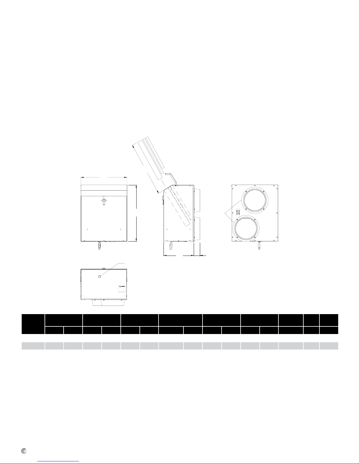
Dimensions
C
A
B
Front
3" Cord- 3 Prong Plug
Model A B C* D E F
in mm in mm in mm in mm in mm in mm V Amps cfm
CM 3000 16 4/5418 20 508 16 1/2420 10 11/
CM 3000 I 18 3/5434 22 3/10524 16 1/2420 13 288 2 3/
* Clearance required for servicing the unit
D E
Side
272 2 3/
16
F
55 8 203 115/V1/60 1 240
10
55 8 203 115/V1/60 1 240
10
Air In
Air Out
Back
Voltage Amp Delivery
Duct Size
Specifications
Model CM 3000 (uninsulated)
Insulated skin can be purchased separately and installed in the eld if required
Kit (included): – Two pcs. of uninsulated 8" ex (UL Listed)
– Four 8" round port collar
– Hanging Chains and hardware
– Installation manual
fantech
Model CM 3000 I (insulated)
Unit (included): – Two 8" round port collar
– Hanging Chains and hardware
– Installation manual
Page 5

Operation
Your Fantech HEPA ltration system incorporates three stages of ltration. Air is drawn from the house via one of the installation examples, found
in this manual, by a powerful efcient EBM fan. The air is cleaned as it passes through the lters, where it is then reintroduced back into the home,
cleaned of the majority of harmful particles.
A semi-annual service schedule must be followed to ensure the HEPA unit is operating at its full potential.
Installation
CM 3000 - Uninsulated model
Option A & B
* Diagrams are examples only. Actual installation may vary.
The return side of the furnace is the recommended location for the HEPA to connect to. The supply side is normally avoided due to the higher static
pressure.
Furnace fan should operate continuous or when HEPA unit is on and running. (Options A & B)
5
Air Return
Option A Option B
Option C
* Diagrams are examples only. Actual installation may vary.
Duct work can be concealed in walls or closets. If the floor is the only choice, special care should be taken to avoid noise or drafts.
fantech
Page 6

6
Installation (Cont'd)
Option D
* Diagrams are examples only. Actual installation may vary.
Unit can be installed in a closet. Air drawn from a hallway or living area is cleaned by the HEPA unit and reintroduced back into a bedroom or other
room.
fantech
Page 7

Installation (Cont'd)
CM 3000 I - Insulated model
* Diagrams are examples only. Actual installation may vary.
In options A & B, the air handler should operate continuously or when HEPA unit is on and operating.
Special care and attention must be given to ensure that all openings in unit, and its duct connections, are sealed, to prevent vehicle
exhaust from entering the unit. Always follow local and state building codes as well as good engineering practices.
7
Option A – Garage installation
Option B – Attic installation connected to return of or handler
fantech
Page 8

8
Installation (Cont'd)
CM 3000 I - Insulated model (continued)
* Diagrams are examples only. Actual installation may vary.
When unit is installed in an unconditioned space such as option C or option D, ductwork (not included) must be insulated and installed according to
local and state codes.
Unit should always be installed in a location that will allow the best possible access for service. Flexible ducting can be restrictive to airflow and
should be kept to a minimum. Avoid excessive turns, cramped ductwork and pinching.
*Proper airflow should be confirmed after installation
30" max
recommended
16.5" of clearance is
needed from front of unit to
access lter for service.
Option C – Independently ducted
Unconditioned
crawl space
Option D – Independently ducted installation in crawled space
fantech
Page 9

Installation (Cont'd)
Whole House – Connecting a ventilation system (HRV/ERV) to a HEPA system
* Diagrams are examples only. Actual installation may vary.
Installation may vary drastically from picture depending on location of all appliances. After installation, proper operation of all the appliances must be
confirmed by a qualified contractor.
3" to 3" (1m)
Fresh air
from outside
Recommended
9
Minimum of 3' - 3"
(1m) separation of
ducts is recommended
Ventilation system (HRV/ERV) should be installed and balanced in accordance with its installation manual.
Furnace fan must be on when either the ventilation system (HRV/ERV) or the HEPA filtration system is operating.
A power damper is recommended to prevent backdrafting of some models of air to air changers, when in the off or standby position. This damper will
be installed between the HRV/ERV and the HEPA unit.
Models Flex100H, VHR100R, 70R, 150R, 1405R, 2005R, SHR1505R, 2005R & 3005R have an automatic backdraft damper build in that
activates when units are in standby position and do not need this additional damper.
All units should be checked after installation for compatibility and proper operation.
fantech
Page 10

10
Service
The useful service life of the lter media in the HEPA Filtration System is directly related to the
volume of air passed through the system and the amount of contaminants in the air. In a typical
residential application, Stage 1 and 2, lters should be replaced every three to six months or when
needed. The Stage 3 HEPA lter should have a life span of two to ve years, again, depending on
the amount of particulate in the air and the maintenance of the Stage 1 pre-lter.
Parts list
Stage 1
Stage 3
Stage 2
Warranty
• The maintenance free motors are
permanently lubricated and are
guaranteed for 7 years. They are
factory balanced to prevent
vibrations and promote silent
operation.
• All other components have a 5 year
limited warranty. (filters not included)
• The limited warranty covers normal
use. It does not apply to any defects,
malfunctions or failures as a result
of improper installation, abuse,
mishandling or misapplication,
fortuitous occurrence or any other
circumstances outside
manufacturer's control.
• The warranty is in effect for 5 years
on parts and 7 years on the motor
after the date of purchase, including
parts replaced during this time
period. If there is no proof of
purchase available, the date
associated with the serial number
will be used for the beginning of the
warranty period. Parts are a 1 year
warranty when replaced after the
initial warranty has expired.
Motor
Stage 1 - Prelter: Air passes through the prelter where larger particles are taken out of the
air. (part number 40195, also available in packs of 24 part numer 40196)
Stage 2 - Carbon: Air passes through the carbon lter where some gases and odors are
removed. (part number 40195, also available in packs of 24 part numer 40196)
Stage 3 - HEPA: Air passes through the certied HEPA media where very small particles are
removed. 99.97% of all particles 0.3 microns and larger that pass through this stage
are removed. Particles smaller than 0.3 microns are also removed with less intensity.
(part number 40193, also available in packs of 12 part numer 40194)
If the air ow through your unit is noticeably reduced, you can inspect the HEPA lter by removing it
and seeing if the lter paper is darkened on the inlet or outer side. If it is, the lter cartridge should
be replaced.
Please contact your local Fantech dealer or call HEPA Customer Service at 1.800.747.1762
regarding replacement of lter media, warranty information or if you have any questions or
concerns about the performance of your HEPA Filtration System.
Replacement parts number for motor (40323) .
• This warranty is the exclusive and only
warranty in effect and all other
warranties either expressed or
implied are invalid.
• Warranty from the manufacturer is
for parts only and does not include
labor or shipping to service or repair
them.
fantech
Page 11

Maintenance
Schedule
Date Type of Service performed Service Technician
11
fantech
Page 12

fantech
Fantech reserves the right to make technical changes.
For updated documentation please refer to www.fantech.net
Fantech®
 Loading...