

Page 1
fantech
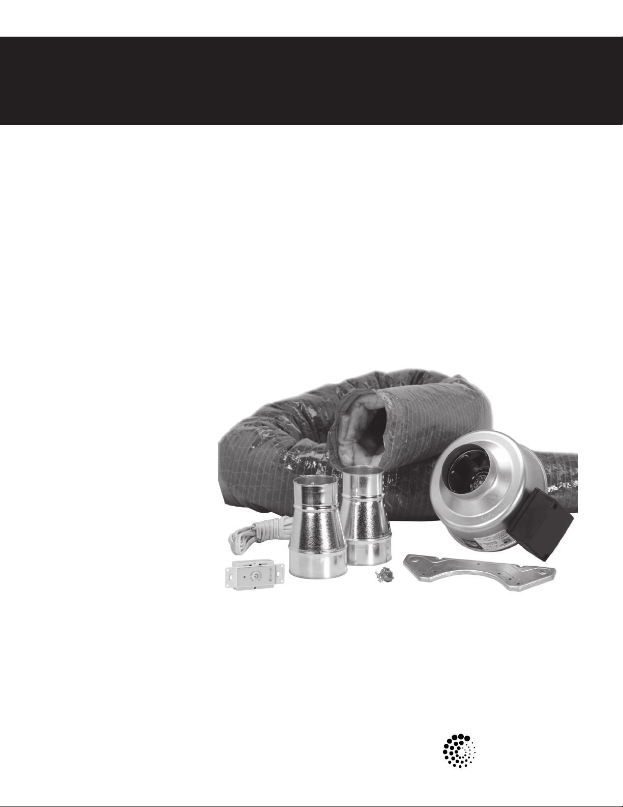
BFRK100
Bath Fan Retrot Kit
BFRK100 Kit Includes:
FG4 fan with mounting bracket, 1 pc
VT 20M Main Control, 1 pc
3" to 4" adapters, 2 pcs
wire connectors. 2 pcs
cable restaint, 1 pc
roll of duct tape, 1 pc
8' flexible insulated 4" duct
12' 14-2 insulated electrical wire
Item #: 450172
Rev Date: 050714
Installation Manual
United States
10048 Industrial Blvd., Lenexa, KS, 66215
Tel.: 800.747.1762 • Fax: 800.487.9915
Canada
50 Kanalflakt Way, Bouctouche, NB, E4S 3M5
Tel.: 800.565.3548 • Fax: 877.747.8116
Page 2
2
Note Warning /
Important
Information Technical
information
Practical tip
note
Read and Save these instructions for future reference.
Not for use with fan/light, heater/fan, or heater/fan/light combination units
Warnings
DO NOT CONNECT POWER SUPPLY until fan is completely installed. Make sure electrical service to the fan is locked in “Off” position
1. All units are suitable for use with solid-state speed control.
2. This unit has rotating parts and safety precautions should be exercised during installation, operation and maintenance.
3. CAUTION: “For General Ventilation Use Only. Do Not Use To Exhaust Hazardous Or Explosive Materials And Vapors.”
4. WARNING: To reduce the risk of fire, electrical shock, or injury to persons-observe the following:
a. Use this unit only in the manner intended by the manufacturer. If you have questions, contact the factory.
b. Before servicing or cleaning, switch power off at service panel and lock service panel to prevent fan from being switched on accidentally.
c. Installation work and electrical wiring must be done by qualified person(s) in accordance with all applicable codes and standards, including fire-
rated construction.
d. The combustion airflow needed for safe operation of fuel burning equipment may be affected by this unit's operation. Follow the heating
equipment manufacturer's guidelines and safety standards such as those published by the National Fire Protection Association (NFPA), the
American Society of Heating, Refrigeration, and Air Conditioning Engineers (ASHRAE) and the local code authorities.
e. When cutting or drilling into wall or ceiling, do not damage electrical wires or other hidden utilities.
f. Exhaust fans must always be vented to the outdoors.
g. Acceptable for use over a bathtub or shower.
h. NEVER place a switch where it can be reached from a tub or shower.
5. WARNING! Check voltage at the fan to see if it corresponds to the motor nameplate.
GUARDS MUST BE INSTALLED WHEN FAN IS WITHIN REACH OF PERSONNEL OR WITHIN SEVEN (7) FEET OF WORKING LEVEL OR WHEN
DEEMED ADVISABLE FOR SAFETY.
fantech
Page 3
Installation
Step 1
Switch power off at service panel and lock the service disconnecting
means to prevent power from being switched on accidentally.
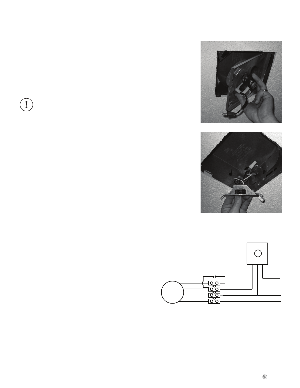
Step 2
In the bathroom, remove the inlet grille.
Step 3
Unplug the motor and remove the motor plate. If convenient, you may
want to remove the motor from the motor plate at this stage.
The motor from your existing fan will not be used when your
retrot installation is complete. However, the motor plate may
be essential for attaching the inlet grille.
3
Step 4
Remove the wiring cover of your existing ceiling mounted bath fan.
Disconnect the power wires to your existing fan.
Step 5
Attach the exible duct provided to the inlet port of the new fan. Tape the
black inner liner to the four inch diameter lip and tape the reective outer
shell to the larger diameter shoulder. Do not leave the insulation material
exposed.
Step 6
Electrical Connection for new fan
A Remove the screws securing the terminal box cover located on
the side of the fan. All fan motor connections are pre-wired to an
electrical terminal strip. Use the cable restraint provided to secure
the wiring through the hole on the electrical box.
B Be sure to place the connector nut over the wiring coming into the
electrical box. There are two open ports on the terminal strip. Using
a small regular screwdriver, tighten the neutral (white) wire of the
incoming supply under the open terminal strip port labeled "N".
Tighten the line (black) wire of the incoming supply under the open
terminal strip port labeled "L". Tighten the ground (green) wire of the
incoming supply under the open terminal strip port labeled with the
Ground symbol. If the terminal strip is not labeled, follow the wiring
diagram found on the inside of the electrical cover.
Step 3
Step 4
VT 20M
C Secure the cable restraint. Secure the incoming supply with the
cable restraint. Replace the fan electrical box cover. All fan motor
and capacitor connections have been pre-wired from the factory. No
additional fan wiring is necessary.
D The other end of the electrical cable will be connected in a later
step.
Step 7
In the attic or crawl space, nd the location of the existing bath fan
and its exhaust duct. Select a location for the new FG 4 fan. The new
fan will be connected to part of the existing exhaust duct so you must
plan to locate the new fan along the line of the existing exhaust duct, no
greater than seven feet from the existing fan. Fan location should allow
sufcient access for service. For applications that require the new FG4
fan to be located more that seven feet from the existing fan, longer
lengths of electrical cable and exible insulated 4” duct can be purchased
separately.
Motor
Brown
Black
Blue
Green
L (Black)
N (White)
Ground
Red
White
120V Supply
Black
fantech
Page 4

4
Installation (Cont'd)
Step 8
Using the wood screws provided, attach the mounting bracket to a
support beam at the selected location. Fan mounting can be at any
point along the duct and in any angle, however, vertical mounting is
recommended to reduce condensation buildup in the fan. If a horizontal
installation is necessary and condensation buildup may pose a problem,
either wrap insulation around the fan or drill a 1/4" hole in the bottom
of the housing (along with an NPT insert [by others] and drain tubing)
allowing condensation to drain.
Step 9
Cut the existing duct 8” above the mounting bracket. Make a second cut
in the duct at approximately 12” from the existing fan, and then remove
this middle section of the existing duct.
Step 10
Attach fan to the mounting bracket with the sheet metal screws provided.
Wiring box should be positioned for easy access. Screws are self tapping
and do not require pilot holes. However, pilot holes (no larger than 3/32" )
are recommended.
Step 11
Connect the section of the existing duct (from the roof cap, wall cap
or soft vent) to the outlet port of the new fan using duct tape. If your
existing exhaust duct is 3” diameter, use one of the 3” to 4” adapters
(supplied in the kit).
Step 10
Step 11 & Step 12
Screw Location
Step 12
Connect the section of the existing duct (from the discharge of the
existing fan) to exible duct (from the inlet on the new fan) using duct
tape. If your existing exhaust duct is 3” diameter, use one of the 3” to 4”
adapters (supplied in the kit). Tape the black inner liner to the four inch
diameter lip and tape the reective outer shell over the top of the inner
liner. Do not leave the insulation material exposed.
Step 13
Uncoil the new electrical cable from the new fan. Loosen the cable
restraint on the existing fan and feed 4” of the new cable through the
restraint, next to the existing electrical cable. Tighten the screws on the
cable restraint of the existing fan.
Step 14
In the bathroom, connect the new cable to the existing power supply
(black wire to black wire, white wire to white wire) using the wire nuts
provided.
Step 15
Carefully push the new connections back into the fan housing (or wiring
box within the fan housing) making sure that no wires will be pinched
before putting the wiring cover and motor plate back into position.
Reattach the fan grille.
Step 16
Install the VT20M fan controller in an electrical box upstream of the fan.
See also the instructions included with the VT20M controller.
Step 13
Step 17
Restore electrical service, switch on and verify airow
fantech
Step 14
Page 5

Warranty
Five (5) Year Warranty
This warranty supersedes all prior warranties
5
DURING ENTIRE WARRANTY PERIOD:
Fantech will repair or replace any part which has a factory defect in
workmanship or material. Product may need to be returned to the
Fantech factory, together with a copy of the bill of sale and identified
with RMA number.
FOR FACTORY RETURN YOU MUST:
• Have a Return Materials Authorization (RMA) number. This may be
obtained by calling Fantech either in the USA at 1.800.747.1762 or
in CANADA at 1.800.565.3548. Please have bill of sale available.
• The RMA number must be clearly written on the outside of the
carton, or the carton will be refused.
• All parts and/or product will be repaired/replaced and shipped back to
buyer; no credit will be issued.
OR
The Distributor may place an order for the warranty part and/or product
and is invoiced. The Distributor will receive a credit equal to the invoice
only after product is returned prepaid and verified to be defective.
FANTECH WARRANTY TERMS DO NOT PROVIDE FOR REPLACEMENT
WITHOUT CHARGE PRIOR TO INSPECTION FOR A DEFECT.
REPLACEMENTS ISSUED IN ADVANCE OF DEFECT INSPECTION ARE
INVOICED, AND CREDIT IS PENDING INSPECTION OF RETURNED
MATERIAL. DEFECTIVE MATERIAL RETURNED BY END USERS SHOULD
NOT BE REPLACED BY THE DISTRIBUTOR WITHOUT CHARGE TO THE
END USER, AS CREDIT TO DISTRIBUTOR’S ACCOUNT WILL BE
PENDING INSPECTION AND VERIFICATION OF ACTUAL DEFECT BY
FANTECH.
THE FOLLOWING WARRANTIES DO NOT APPLY:
• Damages from shipping, either concealed or visible. Claim must be
filed with freight company.
• Damages resulting from improper wiring or installation.
• Damages or failure caused by acts of God, or resulting from improper
consumer procedures, such as:
1. Improper maintenance
2. Misuse, abuse, abnormal use, or accident, and
3. Incorrect electrical voltage or current.
• Removal or any alteration made on the Fantech label control number
or date of manufacture.
• Any other warranty, expressed, implied or written, and to any
consequential or incidental damages, loss or property, revenues, or
profit, or costs of removal, installation or reinstallation, for any breach
of warranty.
WARRANTY VALIDATION
• The user must keep a copy of the bill of sale to verify purchase date.
• These warranties give you specific legal rights, and are subject to an
applicable consumer protection legislation. You may have additional
rights which vary from state to state.
Limitation of Warranty and Liability
This warranty does not apply to any Fantech product or part which has
failed as a result of faulty installation or abuse, incorrect electrical
connections or alterations made by others, or use under abnormal
operating conditions or misapplication of the product or parts. We will
not approve for payment any repair not made by us or our authorized
agent without prior written consent. The foregoing shall constitute our
sole and exclusive warranty and our sole exclusive liability, and is in lieu
of any other warranties, whether written, oral, implied or statutory.
There are no warranties which extend beyond the description on the
page hereof. In no event, whether as a result of breach of contract, or
Warning
Fantech products are designed and manufactured to provide reliable
performance, but they are not guaranteed to be 100% free from
defects. Even reliable products will experience occasional failures and
this possibility should be recognized by the user. If these products are
warranty or alleged negligence, defect incorrect advice or other causes,
shall Fantech be liable for special or consequential damages, including,
but not limited to, loss of profits or revenue, loss of use of equipment or
any other associated equipment, cost of capital, cost of substitute
equipment, facilities or services, downtime costs, or claims of
customers of purchase for such damages. Fantech neither assumes or
authorizes any person to assume for it any other liability in connection
with the sale of product(s) or part(s). Some jurisdictions do not allow the
exclusion or limitation of incidental or consequential damages so the
above limitations and exclusions may not apply to you.
used in a life support ventilation system where failure could result in loss
or injury, the user should provide adequate backup ventilation,
supplementary natural ventilation, failure alarm system, or acknowledge
willingness to accept the risk of such loss or injury.
fantech
Page 6

6
Notes
fantech
Page 7

Notes
7
fantech
Page 8

fantech
Fantech reserves the right to make technical changes.
For updated documentation please refer to www.fantech.net
Fantech®
 Loading...